REACTIONS AND PHOTOCHEMISTRY OF A DISSERTATION
151
REACTIONS AND PHOTOCHEMISTRY OF SAMARIUM(II) COMPLEXES by BRIAN WESLEY KNETTLE, B.S., M.S. A DISSERTATION IN CHEMISTRY Submitted to the Graduate Faculty of Texas Tech University in Partial Fulfillment of the Requirements for the Degree of DOCTOR OF PHILOSOPHY Approved ChairpersoTT of the Committee Accepted Dean of the Graduate School December, 2003
Transcript of REACTIONS AND PHOTOCHEMISTRY OF A DISSERTATION
REACTIONS AND PHOTOCHEMISTRY OF
SAMARIUM(II) COMPLEXES
by
BRIAN WESLEY KNETTLE, B.S., M.S.
A DISSERTATION
IN
CHEMISTRY
Submitted to the Graduate Faculty of Texas Tech University in
Partial Fulfillment of the Requirements for
the Degree of
DOCTOR OF PHILOSOPHY
Approved
ChairpersoTT of the Committee
Accepted
Dean of the Graduate School
December, 2003
ACKNOWLEDGEMENTS
I would like to thank Dr. Robert Flowers, who has been my research mentor for
the last 4+ years. Not only has he set a good example as a scientist, but as an educator as
well. I have been honored to contribute to his research in this time.
I thank Drs. Dominick Casadonte and Bruce Whittlesey for their help during this
time as committee members. Both have provided significant impact upon my progress,
particularly concerning my own proposed research projects.
Special thanks to the members of Dr. Flowers research group. Dr. Prasad
Edemana, Dr. Pramod Mohanta, and Dr. Myeongseob Kim (post-doctoral researchers),
Todd Davis, Yang Zhang, Xiangyi Liu, Pramod Chopade, Jingling (Jason) Jiao (graduate
students). Drew Raines, and Jeremy Gooch (undergraduates), and Dr. Leanne Miller
(visiting professor).
I would be remiss not thanking Dr. Rebecca Miller who has also been a 'visiting'
professor in the lab, but also the General Chemistry Coordinator at TTU, and as such, the
person that I have reported to as a teaching assistant at Texas Tech. It has been a
pleasure working with her in the teaching environment.
Thanks to LaQuetta Purkiss for all her help while teaching and to her husband
David for his assistance with the 500MHz NMR.
Lastly, special thanks to my wife, who despite crying upon the sight of Lubbock,
Texas, has been as supportive as anyone could ever ask for. If not for her, I would have
quit a long time ago. Let's go home.

TABLE OF CONTENTS
ACKNOWLEDGEMENTS ii
ABSTRACT vi
LIST OF TABLES viii
LIST OF FIGURES x
LIST OF ABBREVIATIONS xv
CHAPTER
1. INTRODUCTION 1
1.1 The Lanthanide Elements 1
1.2 Metallic Lanthanide Chemistry 2
1.3 Trivalent Lanthanide Chemistry 4
1.4 Tetravalent Lanthanide Chemistry 7
1.5 Divalent Lanthanide Chemistry 9
2. METHODS AND MATERIALS 17
2.1 Materials 17
2.2 Purifications 17
2.3 Conditions 17
2.4 Instrumentation ^8
3. PROCEDURES AND SYNTHESIS 19
3.1 Preparation of Sml2 19
lU

3.2 Preparation of SmBr2 19
3.3 Preparation of Sm[N(Si(CH3)3)2]2 19
3.4 Preparation of Sml2/Et3N/H20 Reagent 20
3.5 General Procedure for Aldimine Synthesis 20
3.6 General Procedure for Ketimine Synthesis 20
3.7 Synthesis of N-benzyl imine of 3-methyl-2-butanone 21
3.8 Synthesis of N-benzyl imine of pinacolone 21
3.9 Synthesis of N-benzyl imine of m-tolualdehyde 22
3.10 Synthesis of N-benzyl imine of/7-tolualdehyde 22
3.11 Synthesis of N-benzyl imine ofp-anisaldehyde 23
3.12 Synthesis of N-benzyl imine of a,a,a-trifluoro-p-tolaldehyde 23
3.13 Synthesis of N-butyl imine of benzaldehyde 24
3.14 Synthesis of N-benzyl imine of acetophenone 24
3.15 General Procedure for Imine Reactions with Samarium(II) Reagents 25
3.16 General Procedure for Sonochemical Experimentation 25
4. REDUCTION OF IMINES BY SAMARIUM(II) REDUCTANTS 27
4.1 Synthesis of Imines 27
4.2 Samarium(II) Reagent Selection 32
4.3 Reduction of Imines Utilizing Samarium(II) Reagents 35
4.4 Application of Sonochemistry to Sml2-Imine Reactions 45
5. PHOTOCHEMISTRY OF SAMARIUM(II) REAGENTS 52
5.1 Introduction to Photochemistry 52
IV
5.2 Lanthanide Photochemistry 58
5.3 Origin of Electronic Transitions in Lanthanides 61
5.4 Particulars of Samarium Spectroscopy 63
5.5 UV-Vis Spectroscopy of Sm(n) Complexes 66
5.6 Sml2 Absorbance Spectra and Spectroscopy 68
5.7 SmBr2 Absorbance Spectra and Spectroscopy 78
5.8 Sm[N(SiMe3)2]2 Spectra 80
5.9 Sml2-HMPA Spectra 81
6. DISCUSSION 84
6.1 The Role of HMPA in Sml2 Mediated Chemistry 84
6.2 The Selection of Samarium(II) Reagents 88
6.3 Reduction of Imines by Samarium(II) Reagents 93
6.4 Imine Reduction with Applied Ultrasound 97
6.5 Photochemical Activation of Sml2 98
6.6 Samarium(II) Spectroscopy 101
6.7 Conclusions 103
REFERENCES 105
APPENDICES
A. DETERMINATION OF TERM SYMBOLS I l l
B. SPECTRA AND SPECTRAL DATA 117

ABSTRACT
Over the previous twenty years, divalent lanthanide reagents have become
reagents of choice for organic functional group transformations. Samarium diiodide has
made a particularly impressive impact on the way synthetic chemists perform reductions,
reductive couplings of multiple 7t-bonds, and coupling of alkyl halides to ;i-bonds.
It has been shown that the rate of reduction and the reducing ability of
samarium(II) complexes can be influenced by the coordinating ligands and solvent
medium. The most common additive is HMPA, which accelerates many reactions, and
can also alter the stereoselectivity of products. This is due to the electron donating ability
of HMPA to the divalent cation (increasing the reducing power) and the increased steric
bulk about the samarium reductant.
The first portion of this research focused on the behavior of samarium(II)
complexes towards imines. It was found that substitution of Sml2 (which does not
mediate imine reductions) with SmBr2, Sm[N(SiMe3)2]2, or a mixture of Sml2-Et3N-H20
allowed for imine reduction. However, the study showed that profound differences in
reactivity could be related to the choice of ligand. SmBr2 and Sm[N(Si(CH3)3)2]2 were
both effective at reduction of ketimines to amines. Sm[N(Si(CH3)3)2]2 was also able to
reductively couple certain aldimines in a stereoselective manner. The Sml2-Et3N-H20
mixture was found to be effective at coupling both aldimines and ketimines.
It had been previously shown that illumination of Sml2 increased its reducing
power. To further examine this phenomenon, photochemical quenching experiments
VI

were performed upon Sml2 solutions containing a quencher molecule. Experimental rate
constants were calculated for quenching by the N-benzyl imine of acetophenone, styrene,
1-chlorobutane, 2-butanone, and 4-toludine, and were found to be in good agreement
with theoretical rates derived from Marcus theory. This indicates that the electron
transfer is an outer sphere process.
Lastly, a spectroscopic study of several samarium(II) reagents was performed.
Relative quantum yields for Sml2 and SmBr2 were found to be 0.13 and 0.011,
respectively. Molar extinction coefficients were also found for these complexes and
clearly showed that Sml2 is more efficient in the photon absorption process.
vn

LIST OF TABLES
1.1: Reductions of organic halides by Sml2 10
1.2: Reductive coupling of alkyl halides to 2-octanone by Sml2 11
1.3: Effects of cosolvent upon the oxidation potential of Sml2 12
1.4: Reductions utilizing water as a cosolvent by Curran 13
4.1: Results from the investigation of nitrogen substituent on reduction 36
4.2: Results from the study of substituents on an aromatic imine ring at the
para position 38
4.3: Results from reduction of meto-substituted aromatic imine 41
4.4: Results from reduction of aromatic ketimines 43
4.5: Results of reduction of aliphatic ketimines 44
4.6: Results of reduction of cyclic ketimine 45
4.7: Results of Sml2 mediated reduction of imines with applied ultrasound 4&
4.8: Results of reactions with non-imine substrates utilizing ultrasound 49
5.1: Molar extinction coefficients for SmL absorbance maxima 69
5.2: Values used for calculation of the free energies of electron transfer 76
5.3: Comparison of rate constants from theory and experimental data 77
5.4: Molar extinction coefficients for SmBr2 peak maxima 78
5.5: Molar extinction coefficients for Sm[N(SiMe3)2]2 81 5.6: Molar extinction coefficients for SmL-HMPA 82
6.1: Effect of HMPA on coupling product stereoselectivity 87
V l l l

6.2: Rate constants and activation parameters for alkyl iodide and ketone reduction by Sml2, SmL-HMPA, and Sm[N(SiMe3)2]2 91
IX

LIST OF FIGURES
1.1: Synthesis of divalent lanthanide species by Kagan 2
1.2: Reductive coupling of acetophenone utilizing cerium metal 3
1.3: Example of the traditional Birch reduction 3
1.4: Reactions mediated by ytterbium metal by Fujiwara 4
1.5: Baylis-Hillman reaction intermediate utilizing Ln(III) salts 5
1.6: Ln(III)-resin catalyzed Aldol reaction 6
1.7: CAN mediated oxidation by Fisher 7
1.8: Solvent dependent reductive coupling of 1,3-diketone and allyl trimethylsilane 8
1.9: Coupling of multiple 7i-bonds by Sml2 12
1.10: Reduction of achloride by light activated Sml2 15
4.1: Use of an imine as a carbonyl protecting group 27
4.2: Use of imine in the synthesis of an a,a-amino acid 28
4.3: Example of the Staudinger reaction 29
4.4: Examples of natural products containing the vicinal diamine sub-unit 29
4.5: Example of ketone reduction by Ru(II)-diamine by Wagner and Mioskowski 30
4.6: Cisplatin and related 1,2-diamine platinum antitumoral agents 30
4.7: Pathway from imine to vicinal diamine utilizing Sm(II) reagents 31
4.8: Illustration of the potential chelation from ortho substitution 37
4.9: Cyclic voltammograms of (1) SmBr2 (2) Sm[N(SiMe3)2]2 and (3) SmL-Et3N-H20 39
4.10: Possible pathway for p-substituted imine reduction by Sml2-Et3N-H20 40
X

4.11: Application of ultrasound to initiate the reduction of a methoxyaminosilane 47
4.12: Application of ultrasound to accelerate a Diels-Alder reaction 47
5.1: Photochemistry of phenylcyclobutene in acetonitrile and methanol solvents 53
5.2: Scheme for photochemistry of Ru(II) in acidic media 54
5.3: Illustration of the difference between fluorescence and phosphorescence 56
5.4: Terbium(III) chelates for medical imaging 59
5.5: Photoinitiated oxidation of peroxides by Ce " 60
5.6: Reduction of alkyl chloride by excited Sml2 60
5.7: Schematic for Ln(III) electronic transitions 61
5.8: Dorenbos representation for divalent lanthanides 62
5.9: Ground state configuration for f^ species 64
5.10: Configurations for the ^F (left) and ^H (right) states 64
5.11: Splitting of excited states by crystal field 65
5.12: Electronic transitions for the Sm(II) species 66
5.13: UV spectra of Sml2, Sml2-HMPA, SmBr2, and Sm[N(SiMe3)2]2 67
5.14: Beer's law plots for Sml2 68
5.15: Phosphorescence spectrum of Sml2 69
5.16: Overlay of Sml2 (grey) and Cu(dmp)2"^ (black) emission spectra 71
5.17: Stem Volmer plot for the quenching of SmL with 2-butanone 72
5.18: Stern-Volmer plot for quenching of SmL with 1-chlorobutane 72
5.19: Stern-Volmer plot for quenching of Sml2 with aromatic imine 73
5.20: Stern-Volmer plot for quenching of SmL with/7-toludine 74
XI

5.21: Stern-Volmer plot for quenching of SmL with styrene 75
5.22: Beer's Law plots for SmBr2 78
5.23: Phosphorescence spectra for 5 mM solutions of (top) Sml2 and (bottom) SmBr2..79
5.24: Beer's law plots of Sm[N(SiMe3)2]2 80
5.25: Beer's law polts of Sml2-HMPA 82
6.1: (left) Crystal structure of Sml2(HMPA)4. (right) Crystal structure of
[Sm(HMPA)6]l2 85
6.2: Coupling of vinyloxirane to ketone mediated by Sm(II) 87
6.3: Pathway of Sml2 and Sml2-HMPA reduction of vinylepoxides 88
6.4: Mechanism for reduction of nitro group by Sm[N(SiMe3)2]2 90
6.5: Equilibrium alteration through precipitation of Sm(III) 92
6.6: Products of unsymmetrical conjugated double bond reduction by Sml2-
Et3N-H20 93
6.7: Pathway for reduction through benzylic position of imines 95
6.8: Models of (left) unsubstituted iminyl radical (right) substituted iminyl radical
from Spartan modelling 96
6.9: Possible coupling reactions based on photoexcited SmL 101
A-1: 2p orbital representation 112
A-2: 2p orbitals after numerical assignment 112
A-3: 2p orbitals after carbon valence electrons are accommodated 112
A-4: Correlation of orbital angular momentum to term symbol 113
A-5: Calculated total angular momentum quantum numbers for carbon 114 A-6: 4f orbital representation 115 A-7: 4f orbitals after numerical assignment 115
Xll
A-8: 4f orbitals after addition of valence electrons 115
B-1: H NMR of products from reduction of the N-butyl imine of benzaldehyde 117
B-2: H NMR of products from reduction of the N-benzyl imine of benzaldehyde 118
B-3: H NMR of products from reduction of the N-benzyl imine of p-methyl benzaldehyde 119
B-4: H NMR of products from reduction of the N-benzyl imine of p-methoxy benzaldehyde 120
B-5: H NMR of products from reduction of the N-benzyl imine of /?-trifluoromethyl benzaldehyde 121
B-6: H NMR of products from reduction of the N-benzyl imine of m-methyl benzaldehyde 12 T
B-7: H NMR of products from reduction of the N-benzyl imine of acetophenone 123
B-8: H NMR of products from reduction of the N-benzyl imine of
3-methyl-2-butanone 124
B-9: 'H NMR of products from reduction of the N-benzyl imine of pinacolone 125
B-10: ^H NMR of products from reduction of the 2-phenyl-l-pyrroline 126
B-11: '^C NMR of products from reduction of the 2-phenyl-l-pyrroline 127
B-12: 'H NMR of N-butyl imine of benzaldehyde 128
B-13: 'H NMR of N-benzyl imine of benzaldehyde 129
B-14: 'H NMR of N-benzyl imine of p-methyl benzaldehyde 130
B-15: 'H NMR of N-benzyl imine of p-methoxy benzaldehyde 131
B-16: 'H NMR of N-benzyl imine of p-trifluoromethyl benzaldehyde 132
B-17: 'H NMR of N-benzyl imine of w-methyl benzaldehyde 133
xin
B-18: ^H NMR of N-benzyl imine of acetophenone 134
B-19: 'H NMR of N-benzyl imine of 3-methyl-2-butanone 135
B-20: 'H NMR of N-benzyl imine of pinacolone 136
XIV

LIST OF ABBREVIATIONS
DME: 1,2-Dimethoxyethane, CH3OCH2CH2OCH3. Common organic solvent.
DMP: 2,9-dimethyl-l,10-phenanthroline, also known as neocuproine. A common metal ligand.
Ln(II) and Ln(III): Generic symbols for divalent and trivalent lanthanide metal cations, respectively.
HMPA: Hexamethylphosphoramide, [(CH3)2N]3P(0). A common additive to Sml2, HMPA increases the reduction power and can have stereochemical impact.
HOMO: Highest Occupied Molecular Orbital. In electronic transitions, the orbital from which the electron is excited.
ISC: InterSystem Crossing. Typically, an electronic transition between two energy levels, during which, the electron undergoes a spin inversion.
LUMO: Lowest Unoccupied Molecular Orbital. In electronic transitions, the orbital to which an electron is excited.
THF: Tetrahydrofuran, C4H8O. Common organic solvent.
TMS: Tetramethylsilane, Si(CH3)4. A reference utilized in NMR spectroscopy.
XV

CHAPTER 1
INTRODUCTION
1.1 The Lanthanide Elements
The lanthanides are the elements of the periodic table of atomic numbers 57
(lanthanum, 41*) through 71 (lutetium, 4f'^). These elements represent the filling of the
4f orbitals with 14 electrons. The lanthanides share some physical and chemical
properties, such as a silver-white appearance, an aptitude for forming complexes with
neutral molecules and a stable trivalent oxidation state.' In fact, their similar nature has
historically made their individual separation complicated, which has been reflected in
their relative high cost compared to transition metals of similar abundance in the earth's
crust. Early methods for separation of the individual elements from the trivalent state
relied on complexing the lanthanide ion with a tightly bound ligand such as EDTA,
followed by elution through a cation exchange column. This yielded the individual
elements in reverse order of atomic number (Lu is first. La is last). Newer methods
utilize extraction into tri-n-butylphosphine oxide and can give purities over 99% for each
element.
Initial work utilizing the lanthanide elements was limited until the seminal works
of Kagan" and Luche.^ Kagan found that the divalent lanthanide species Sml2 or Ybl2
could be made from the reaction of the lanthanide metal with 1,2-diiodoethane in
tetrahydrofuran (Figure 1.1). Furthermore, Kagan reported that both divalent species
were capable of reducing conjugated double bonds or carbonyls, and that Sml2 was

efficient at the reduction of alkyl iodides and bromides as well as Grignard type
couplings between alkyl halides and ketones.
Ln -I- / • Lnl2 + //
^^"2 CH2 (Ln = Sm, Yb)
Figure 1.1: Synthesis of divalent lanthanide species by Kagan.
Two years previous to Kagan's seminal work, Luche found that a,p-unsaturated
ketones were converted into allylic alcohols by utilizing samarium or cerium. This work
differed from that of Kagan, as Luche utilized a mixture of trivalent lanthanide chloride
(hydrate) and sodium borohydride instead of a directly made divalent species. This lead
to Luche's inabilty to postulate a single mechanism for the reduction process, though this
should not undermine the impact of the work toward lanthanide mediated chemistry.
The works of Kagan and Luche serve a second purpose in this work. From these
initial studies, three of the four accessible oxidation states of the lanthanides are
illustrated, namely the metallic, uncharged state, as well as the divalent and trivalent
species. The fourth state, tetravalent, is predominantly due to cerium-based chemistry. A
brief examination of the chemistry each of the oxidation states follows.
1.2 Metallic Lanthanide Chemistry
The neutral metals of all the lanthanides act as reducing agents. This property
allows for some use of the metals directly in synthesis. Work by Imamoto in 1982
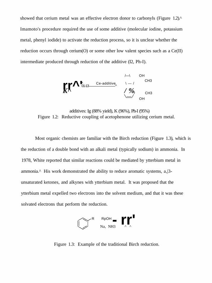
showed that cerium metal was an effective electron donor to carbonyls (Figure 1.2).
Imamoto's procedure required the use of some additive (molecular iodine, potassium
metal, phenyl iodide) to activate the reduction process, so it is unclear whether the
reduction occurs through cerium(O) or some other low valent species such as a Ce(II)
intermediate produced through reduction of the additive (I2, Ph-I).
rr^' /—\ OH
^ Ce-additive \ — / 01-13 ^
K^ / %
CH3
CH3
OH
additives: Ig (88% yield), K (96%), Ph-I (95%) Figure 1.2: Reductive coupling of acetophenone utilizing cerium metal.
Most organic chemists are familiar with the Birch reduction (Figure 1.3), which is
the reduction of a double bond with an alkali metal (typically sodium) in ammonia. In
1978, White reported that similar reactions could be mediated by ytterbium metal in
ammonia.^ His work demonstrated the ability to reduce aromatic systems, a,|3-
unsaturated ketones, and alkynes with ytterbium metal. It was proposed that the
ytterbium metal expelled two electrons into the solvent medium, and that it was these
solvated electrons that perform the reduction.
R RpOH - rr' Na, NH3 ^ ^
Figure 1.3: Example of the traditional Birch reduction.
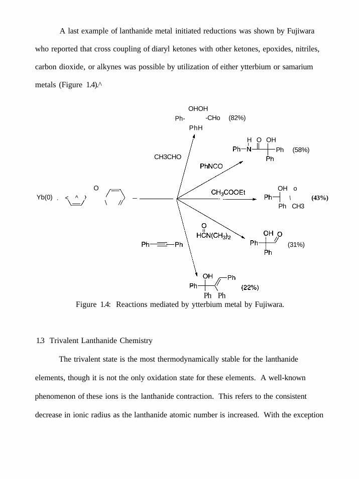
A last example of lanthanide metal initiated reductions was shown by Fujiwara
who reported that cross coupling of diaryl ketones with other ketones, epoxides, nitriles,
carbon dioxide, or alkynes was possible by utilization of either ytterbium or samarium
metals (Figure 1.4).
Yb(0) . < ^
O
\ //
OHOH
Ph- -CHo (82%)
PhH
H O OH
CH3CHO
OH o
Ph (58%)
\ (43%) Ph CH3
(31%)
Ph Ph Figure 1.4: Reactions mediated by ytterbium metal by Fujiwara.
1.3 Trivalent Lanthanide Chemistry
The trivalent state is the most thermodynamically stable for the lanthanide
elements, though it is not the only oxidation state for these elements. A well-known
phenomenon of these ions is the lanthanide contraction. This refers to the consistent
decrease in ionic radius as the lanthanide atomic number is increased. With the exception
of cerium, which has an accessible tetravalent state, the trivalent ions do not act as
electron donating species. Despite this, this oxidation state is not uncommon in synthetic
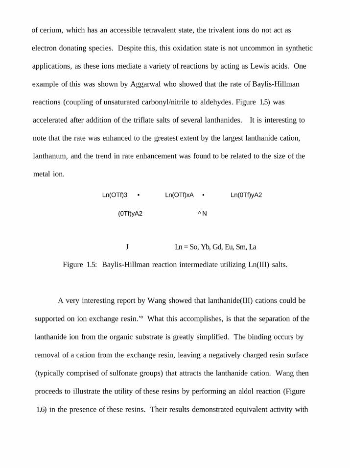
applications, as these ions mediate a variety of reactions by acting as Lewis acids. One
example of this was shown by Aggarwal who showed that the rate of Baylis-Hillman
reactions (coupling of unsaturated carbonyl/nitrile to aldehydes. Figure 1.5) was
accelerated after addition of the triflate salts of several lanthanides. It is interesting to
note that the rate was enhanced to the greatest extent by the largest lanthanide cation,
lanthanum, and the trend in rate enhancement was found to be related to the size of the
metal ion.
Ln(OTf)3 • Ln(OTf)xA • Ln(0Tf)yA2
(0Tf)yA2 ^ N
J Ln = So, Yb, Gd, Eu, Sm, La
Figure 1.5: Baylis-Hillman reaction intermediate utilizing Ln(III) salts.
A very interesting report by Wang showed that lanthanide(III) cations could be
supported on ion exchange resin.'° What this accomplishes, is that the separation of the
lanthanide ion from the organic substrate is greatly simplified. The binding occurs by
removal of a cation from the exchange resin, leaving a negatively charged resin surface
(typically comprised of sulfonate groups) that attracts the lanthanide cation. Wang then
proceeds to illustrate the utility of these resins by performing an aldol reaction (Figure
1.6) in the presence of these resins. Their results demonstrated equivalent activity with
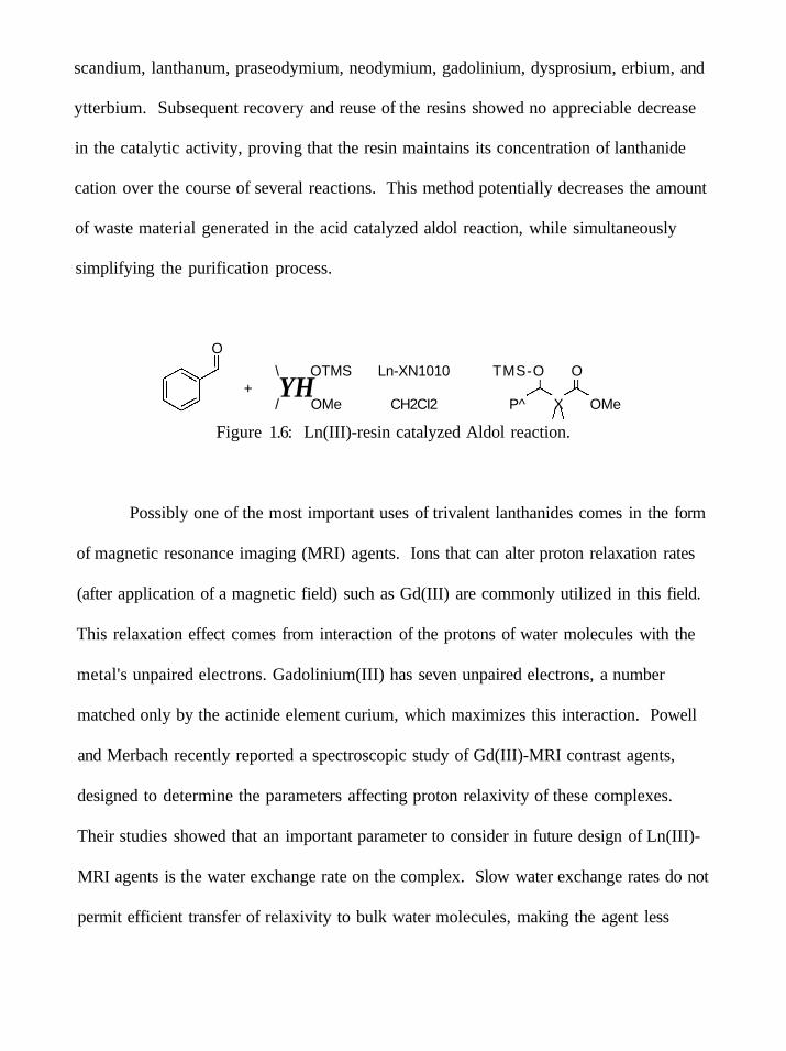
scandium, lanthanum, praseodymium, neodymium, gadolinium, dysprosium, erbium, and
ytterbium. Subsequent recovery and reuse of the resins showed no appreciable decrease
in the catalytic activity, proving that the resin maintains its concentration of lanthanide
cation over the course of several reactions. This method potentially decreases the amount
of waste material generated in the acid catalyzed aldol reaction, while simultaneously
simplifying the purification process.
O
\ OTMS Ln-XN1010 TMS-O O + YH
/ OMe CH2CI2 P^ X OMe
Figure 1.6: Ln(III)-resin catalyzed Aldol reaction.
Possibly one of the most important uses of trivalent lanthanides comes in the form
of magnetic resonance imaging (MRI) agents. Ions that can alter proton relaxation rates
(after application of a magnetic field) such as Gd(III) are commonly utilized in this field.
This relaxation effect comes from interaction of the protons of water molecules with the
metal's unpaired electrons. Gadolinium(III) has seven unpaired electrons, a number
matched only by the actinide element curium, which maximizes this interaction. Powell
and Merbach recently reported a spectroscopic study of Gd(III)-MRI contrast agents,
designed to determine the parameters affecting proton relaxivity of these complexes.
Their studies showed that an important parameter to consider in future design of Ln(III)-
MRI agents is the water exchange rate on the complex. Slow water exchange rates do not
permit efficient transfer of relaxivity to bulk water molecules, making the agent less

efficient. One method for accomplishing this is to crowd the metal center with
coordinating ligands, leaving minimal spacing for water molecules to approach the metal
cation. This favors a dissociative exchange mechanism wherein the coordination number
about the lanthanide decreases from nine (favored by Gd " complexes) to eight, resulting
in loss of a water molecule.
1.4 Tetravalent Lanthanide Chemistry
The tetravalent oxidation state is limited to cerium, praseodymium, and terbium,
though the latter two are not commonly observed under standard laboratory conditions.
Cerium(rV) conversely, is a common oxidizing agent in synthesis. Ceric ammonium
nitrate (CAN) is a very prevalent oxidant, mediating dehydrogenations,'" oxidative
addition of ketones to conjugated dienes,'^ as well as many other oxidative reactions.
One unique application of ceric ammonium nitrate was published by Fisher in
1988. This work describes a series of experiments where l-(4-methoxyphenyl)-2-(4-
substituted-phenyl)ethanols were oxidized with CAN to provide anisaldehyde (Figure
1.7).'" This was a model system for oxidative cleavage of softwood lignin to vanillin,
which is a reaction of importance in wood chemistry.
H 3 0 0 ^ ! ^ ^
OHH
H H
X - ^ ^ ^ H3C0^/ V C H O
X = H, CI, CH3, OCH3, NO2 Figure 1.7: CAN mediated oxidation by Fisher.

An important aspect to lanthanide redox chemistry that often plays an important
role in either the rate of reaction or the product distribution is the relationship between
complex and solvent. Recent work by Flowers has shown that ceric -n-butylammonium
nitrate (CTAN) has a strong dependence with respect to solvent medium in the coupling
of non-cyclic 1,3-diketones, P-keto esters and P-keto silyl enol ethers to allyl
trimethylsilane. In acetonitrile, the allylation product was produced in high yields (from
62-81%), but in the non-polar solvent CH2CI2, the dihydrofuran product was formed with
similar yields (62-78%).'^ This was explained by assuming that after the initial allylation
coupling occurred (forming a radical species as the intermediate), a second oxidation
occurs. This second oxidation forms a cation species, stabilized by solvent, which allows
for an elimination to occur (yielding the allylation product). In CH2CI2, the intermediate
cation is not well stabilized by solvent, so a cyclization occurs to form an 0x0 stabilized
cation instead of the allylation product (Figure 1.8).
O O
CTAN/CH3CN
Ri
O O .SiMes
CTAN/CHaCi
SiMe-i
Figure 1.8: Solvent dependent reductive coupling of 1,3-diketone and allyl trimethylsilane.
Flowers has also reported that the CAN and CTAN complexes have similar
oxidation potentials (within experimental error of each other in acetonitrile). Despite this

similarity, the cation change (NH4* to N(«-butyl) 4 ) has an effect on the relative rates of
oxidation of substrate. This report shows that CTAN oxidized substrates (specifically,
methyl acetoacetate, 1,3-cyclohexanedione, and (trimethylsiloxy)-3-penten-2-one) at a
rate approximately half as fast as CAN. This finding is suggests that the countercation is
associated to some extent with the cerium(IV) complex.'^ It is clear from these two
works that there are many parameters that must be carefully considered in lanthanide
mediated redox chemistry.
1.5 Divalent Lanthanide Chemistry
The divalent oxidation state is stable for samarium, europium, and ytterbium. In this
state, these metals act as single electron donating agents. The fundamental work of
Kagan has initiated a great deal of research into this valence state. SmL has been shown
to be a versatile single electron donor to a variety of functional groups. SmL is known to
perform reduction of alkyl halides,'* carbonyls,'^ and couplings between alkyl halide-
ketone, vinyl halide-ketone, and olefin-ketone ' mixtures. Other substituted Sm(II)
complexes are also known to be particularly effective in some reductions such as SmBr2
(pinacol coupling of ketones)^^ and SmBr2-HMPA (reduction of ketimines) P however
these complexes have not yet been shown to be as versatile as SmL. Ytterbium and
europium(II) also act as reducing agents, though neither reagent is a powerful as SmL.
Ytterbium thiolates are known to perform pinacol couplings of aromatic aldehydes with a
moderate preference for the d:l pair (approximately 3:1), ^ and either metal can act as a
Grignard reagent (with iodobenzene),^^ so there are some obvious similarities with
samarium(II) complexes; still samarium(II) remains the divalent lanthanide of choice.
Sml2 promotes three general types of reductions; the reduction of a functional group
(for example, alkyl halides), reductive coupling between halides and u-bonds (Grignard
or Barbier type couplings), and reductive coupling of two 7i-bonds (for example, pinacol
coupling of ketones). The seminal work by Kagan illustrates the former two cases in
detail. In this work, a number of organic halides were reduced to alkanes with Sml2
(Table 1.1).
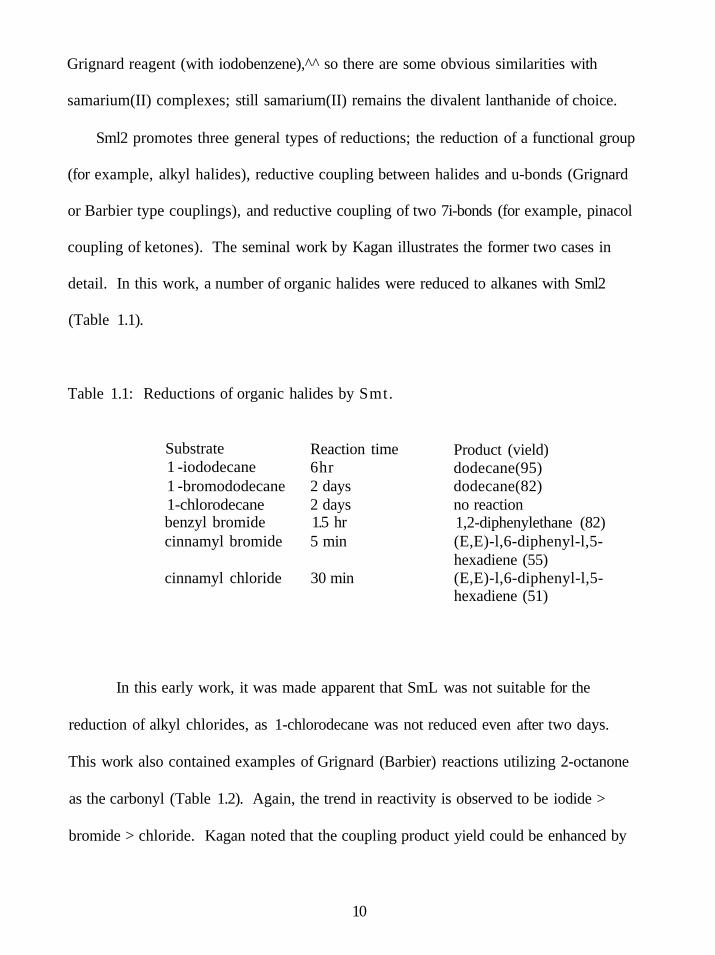
Table 1.1: Reductions of organic halides by Smt.
Substrate 1 -iododecane 1 -bromododecane 1-chlorodecane benzyl bromide cinnamyl bromide
cinnamyl chloride
Reaction time 6hr 2 days 2 days 1.5 hr 5 min
30 min
Product (vield) dodecane(95) dodecane(82) no reaction 1,2-diphenylethane (82) (E,E)-l,6-diphenyl-l,5-hexadiene (55) (E,E)-l,6-diphenyl-l,5-hexadiene (51)
In this early work, it was made apparent that SmL was not suitable for the
reduction of alkyl chlorides, as 1-chlorodecane was not reduced even after two days.
This work also contained examples of Grignard (Barbier) reactions utilizing 2-octanone
as the carbonyl (Table 1.2). Again, the trend in reactivity is observed to be iodide >
bromide > chloride. Kagan noted that the coupling product yield could be enhanced by
10

addition of catalytic amounts of FeCh or addition of the alkyl halide in excess.
Particularly in reactions involving bromide or chloride substrates, it was noted that
formation of significant amounts of 7,8-dimethyl-7,8-tetradecanediol (the pinacol
coupling from two carbonyl 7t-bonds) occurred.
Table 1.2: Reductive coupling of alkyl halides to 2-octanone by SmL.
Substrate Reaction time Yield n-butyl iodide n-butyl bromide n-butyl chloride sec-butyl bromide tert-hutyl bromide
8hr 1 day 6 days 1.5 day 4 days
76 67 8 27 9
The fact that pinacol formation occurred in certain reactions has not escaped the
notice of other researchers. Chiara illustrated one example of this type of coupling in
1998, which utilized a pinacol-type coupling of a intermolecular ketone and imine as the
last step in the synthesis of trehazolamine (an inhibitor of the enzyme trehalase). It was
particularly important, as is the case for most natural products, that the final product
contained the correct stereochemical assignments. In this case, a yield of 88% of the syn
isomer could be directly obtained by use of SmL (Figure 1.9).
11

OBn /
Sml2 BnC, y O H
BnO OBn OBn Figure 1.9: Coupling of multiple 7t-bonds by Sml2.
Sml2 is traditionally made in THF solution; however, other solvents are also utilized.
Work by Namy and Kagan showed that preparation of Sml2 in pivalonitrile instead of
THF gave much higher regioselectivities for the Barbier reaction when using allylic
halides. They also found that reaction rates were somewhat slowed by this solvent
change, but were accelerated by addition of Nil2 in catalytic amounts.
The effects of different solvents upon the reactivity of Sml2 have been studied to
some extent in terms of the change in thermodynamic reduction potential. SmL displays
a wide range of reduction potentials dependent on the solvent. Studies by Flowers have
shown that the Sml2 oxidation potential can be shifted by almost a full volt by addition of
a strongly coordinating cosolvent (Table 1.3)."
Table 1.3: Effects of cosolvent upon the oxidation potential of Sml2.
Cosolvent None TMP DBU PMP TMU HMPA DMPU
E„v(V) -1.33 -1.80 -1.84 -1.90 -2.04 -2.05 -2.21
AE(
0.47 0.51 0.57 0.71 0.72 0.88
12

One cosolvent not presented by Flowers in this work is water. Water is not
incapable of being a cosolvent, however, it is more commonly utilized as a proton source.
Interesting work by Curran in 1993 gave evidence that water can play both roles of
proton donor and rate enhancing cosolvent simultaneously. In this work, several ketones
and iodides were allowed to react with Smli for a period of time with and without water
present. It was found that the reactions in the presence of water contained significantly
more reduction product that the reactions lacking water, which consisted of largely
unreacted starting materials (Table 1.4). ^
Table 1.4: Reductions utilizing water as a cosolvent by Curran.
Reactant 1 1 2 2 3 3 4 4 5 5
Water no yes no yes no yes no yes no yes
Time (min) 10 10 10 10 1 1 60 60 300 300
Reactants: (1) 1,3-diphenylacetone, (2) ethyl cinnamate. iodododecane, (5) o--allyloxyiodobenzene.
Ratio (R:P) 100:0 1:99 100:0 0:100 66:34 1:99 88:12 29:71 80:20 36:64
(3) diphenyl sulfoxide, (4) 1-
Another cosolvent of dramatic importance is HMPA. This compound increases
the reduction potential of Sml2 by 0.72V. This allows for reduction of difficult substrates
not readily reduced by Sml2 alone, such as alkyl chlorides. Work by Inanaga showed that
the Sml2-HMPA system reduced alkyl iodides and bromides within a few minutes and
13

chlorides within a few hours.^^ This was a significant improvement over the rate of Smlj
alone, which shows little reactivity toward chlorides, and is relatively slow for bromides.
HMPA is possibly the most common additive in Smt mediated reactions.
However, HMPA is known to be carcinogenic and as such, attempts to minimize the use
of this useful ligand should be performed. One of the methods for eliminating the use of
HMPA is to utilize a different coordinating ligand. It is already known that SmBr2
behaves in a different fashion than Sml2 in that it preferentially reduces a carbonyl even
in the presence of a thermodynamically easier group (i.e., iodide).^° Samarium(II) triflate,
Sm(0Tf)2, in DME gives high yields for Barbier type reactions, but complicated mixtures
when utilizing Grignard methodologies.^' Sm[N(Si(CH3)3)2]2 was shown to have an
unusual bent structure by Evans^^ and has been found to reduce alkyl iodides at rates
faster than Sml2 or Sml2-HMPA.^^ In spite of this evidence that other complexes than
Sml2 and Sml2-HMPA have great potential in synthesis, it seems that little work has
pursued expanding their roles in synthetic organic chemistry.
One functional group that has not been effectively reduced by Sml2 is the imine
group. Reduction of this group requires either metal catalysts,'''* or reflux conditions.^^ It
would be of interest to find samarium(II) complexes that could mediate this reduction
without utilization of these conditions. An examination of the reactivity of complexes
versus this particular functional group may provide insight into the reactivity of
alternative Sm(II) complexes.
Other alternatives to HMPA addition do not involve the addition of another
compound to the mixture. These methods include sonochemical and photochemical
14

activation. In some aspects, these methods are simpler than the use of additives, because
they further the utility of Sml2 which is much better understood mechanistically than any
of the other samarium(n) reagents. Very little work has been done using sonochemical
methods to activate Sml2 (aside from breaking aggregates of SmBr2) though Banik has
published some work concerning samarium metal reduction of nitro compounds with
ultrasound application.^^ Similarly, photochemical excitation of Sml2 has been largely
overlooked save for a work by Ogawa in 1997 that showed that application of a photon
source to solutions of SmL allowed for reductions of alkyl chlorides to be mediated,^^ and
a series of papers by Molander that utilize light to also reduce a chloride group in the
synthesis of seven, eight, or nine membered carbocycles (Figure 1.10). *"'*° In this case,
activation of Sml2 with light produced the seven membered product in a 70% yield,
which when compared to Sml2-HMPA was an increase in yield of 34%. This is a clear
case where HMPA is not the additive of choice, yet little other work has attempted to
further this photochemical activation to any functional group other than alkyl chlorides.
O O-
Sml2/Nil2(2%)
+hv
Figure 1.10: Reduction of a chloride by light activated SmL.
There are two main goals to this project. The first goal is to examine the
influence of coordinative ligands about Sm(II) and their effects upon the reduction and
15

reductive coupling of imine containing molecules. The second goal of this project is to
perform an initial examination of sonochemical and photochemical excitations of SmL.
These activation methods are anticipated to increase the effective reduction power of
Sml2 and allow for the reduction of functional groups previously unknown in
samarium(II) chemistry without the addition of cosolvents such as the toxic (but
frequently utilized) chemical, HMPA. It is expected that these methods will allow for
removal of HMPA from synthetic work, which not only expands the field of samarium
chemistry, but also makes it a safer field for the chemists who perform it.
16
CHAPTER 2
METHODS AND MATERLVLS
2.1 Materials
Chloroform-d was purchased from Cambridge Isotope Laboratories, Inc. Imine
containing molecules were synthesized in house from condensation of the appropriate
amine with the appropriate carbonyl and are described in greater detail later in this work.
All other chemicals were purchased from Aldrich.
2.2 Purifications
Tetrahydrofuran, diethyl ether, and pentane solvents were distilled from sodium
benzophenone under nitrogen atmosphere. Hexamethylphosphoramide was distilled
under vacuum from either P2O5 or CaO. Lithium bromide and tetrabutylammonium
hexafluorophosphate were dried under vacuum at 100°C. All carbonyl containing
molecules were distilled from MgS04 prior to use. All other chemicals were used
without further purifications.
2.3 Conditions
All air sensitive reactions were performed either in an Innovative Technology,
Inc. System One drybox, or under nitrogen atmosphere utilizing standard Schlenck line
equipment. Glassware, syringes, and other utensils were either flame dried or heated in
an oven to a minimum of 110°C prior to use. Teflon stopper cuvettes were utilized for all
spectroscopic experiments.
17

2.4 Instrumentation
Cyclic voltammetry experiments were performed on a BAS lOOBAV MF-9063
Electrochemical Workstation.
UV-Vis experiments were performed on a Shimadzu UV-1601 UV-Visible
Spectrophotometer controlled by UVProbe (version 1.11) software.
Luminescence experiments were performed on a Photon Technology International
fluorimeter utilizing a XenoFlash power supply and MD-5020 motor driver. This
equipment was controlled by the FeliX32 Analysis Version 1.0 (build 44) software
package.
'H NMR was performed on either a Varian 300 or Varian 500 MHz spectrometer.
Chemical shifts are referred to TMS.
C NMR was performed on a Varian 125 MHz spectrometer. Chemical shifts are
referred to TMS.
Sonication experiments were performed on a Sonics & Materials Inc. model
VC601 VibraCell operating at a fixed frequency of 20 kHz.
Spartan Essential software (version 1,0,2) by Wavefunction Inc. was utilized for
the determination of molecular diameters of reagents involved in dynamic quenching
experiments.
18
CHAPTER 3
PROCEDURES AND SYNTHESIS
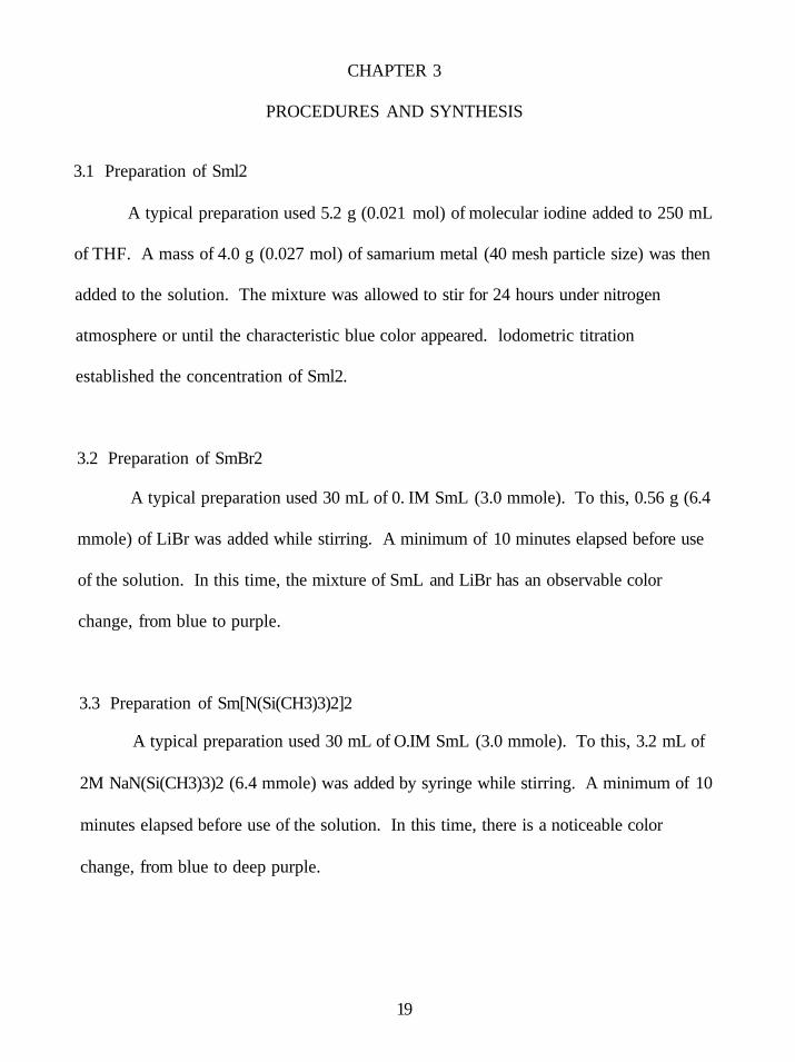
3.1 Preparation of Sml2
A typical preparation used 5.2 g (0.021 mol) of molecular iodine added to 250 mL
of THF. A mass of 4.0 g (0.027 mol) of samarium metal (40 mesh particle size) was then
added to the solution. The mixture was allowed to stir for 24 hours under nitrogen
atmosphere or until the characteristic blue color appeared. lodometric titration
established the concentration of Sml2.
3.2 Preparation of SmBr2
A typical preparation used 30 mL of 0. IM SmL (3.0 mmole). To this, 0.56 g (6.4
mmole) of LiBr was added while stirring. A minimum of 10 minutes elapsed before use
of the solution. In this time, the mixture of SmL and LiBr has an observable color
change, from blue to purple.
3.3 Preparation of Sm[N(Si(CH3)3)2]2
A typical preparation used 30 mL of O.IM SmL (3.0 mmole). To this, 3.2 mL of
2M NaN(Si(CH3)3)2 (6.4 mmole) was added by syringe while stirring. A minimum of 10
minutes elapsed before use of the solution. In this time, there is a noticeable color
change, from blue to deep purple.
19
3.4 Preparation of Sml2/Et3N/H20 Reagent
A typical preparation used 30 mL of 0. IM Sml2 (3.0 mmole). To this,
approximately 0.85 mL (6.0 mmole) of triethylamine and 0.15 mL H2O (7.5 mmole)
were added while stirring. The reagent mixture was used immediately after the additions
occurred.
3.5 General Procedure for Aldimine Synthesis
In a dried 50 mL round bottom flask equipped with a magnetic stir bar,
approximately 25 mL of pentane and 3g of 4A molecular sieves were added.
Approximately 3 mL of the appropriate aldehyde was added via syringe. To this mixture,
the appropriate amine was added in two-fold excess, dropwise. The mixture was allowed
to stir for 24 hours. After this time, the mixture was filtered, washing the filtrate with 30
mL of additional pentane. The remaining solution was purified by removing the volatile
pentane under rotary evaporation and then subjecting the crude product to Kugelrohr
distillation in order to obtain the pure aldimine. Aldimines were stored in capped vials
under nitrogen atmosphere to prevent their decomposition back into the original starting
materials.
3.6 General Procedure for Ketimine Synthesis
In a dried 50 mL round bottom flask equipped with a magnetic stir bar,
approximately 25 mL of pentane, 3 g of 4A molecular sieves, and 500 mg of Amberlyst-
15 were added. In this case, the Amberlyst-15 is a necessary acid catalyst.
20

Approximately 3 mL of the appropriate ketone was added via syringe. To this mixture,
the appropriate amine was added in two-fold excess, dropwise. The mixture was allowed
to stir for 24 hours. After this time, the mixture was filtered, washing the filtrate with 30
mL of additional pentane. The pentane solution was then purified by removal of the
volatile pentane under rotary evaporafion, and then subjecting the crude product to
Kugelrohr distillation in order to obtain the pure ketimine. Ketimines were stored in
capped vials under nitrogen atmosphere to prevent their decomposition back into the
original starting materials.
3.7 Synthesis of N-benzyl imine of 3-methyl-2-butanone
Exactly 2.2 mL of benzylamine (20 mmol) was added to a 100 mL round bottom
containing a mixture of 2.7 mL of 3-methyl-2-butanone (25 mmol), approximately 30 mL
o
pentane, 500 mg Amberlyst-15, and 3 g of 4-A molecular sieves. The mixture was
stirred overnight, and then filtered, washing the filtrate with pentane. The pentane was
removed by rotary evaporation first and then the final product isolated after 24 hours
under vacuum at room temperature. Yield 88%. 'H (500 MHz, CDCI3): 7.21-7.35 (m,
5H), 4.50 (s, 2H), 2.54-2.62 (m, IH), 1.85-1.86 (t, 3H), 1.13-1.15 (d, 6H). '^C (125
MHz,CDCl3): 175.2, 140.6, 128.2, 127.5, 126.3,54.6,40.1, 19.8, 14.9.
3.8 Synthesis of N-benzyl imine of pinacolone
Exactly 2.2 mL of benzylamine (20 mmol) was added to a 100 mL round bottom
containing a mixture of 3.2 mL pinacolone (25 mmol), approximately 30 mL pentane.
21

500 mg Amberlyst-15, and 3 g 4-A molecular sieves. The mixture was stirred overnight,
and then filtered, washing the filtrate with pentane. The pentane was removed by rotary
evaporation first and then the final product isolated after 24 hours under vacuum at room
temperature. Yield 46%. 'H (500 MHz, CDCI3): 7.21-7.39 (m, 5H), 4.52 (s, 2H), 1.88 (s,
3H), 1.19 (s, 9H). '^C (125MHz, CDCI3): 176.4, 141.0, 128.2, 127.2, 126.2, 54.3, 40.7,
27.8, 13.5.
3.9 Synthesis of N-benzyl imine of m-tolualdehyde
To a 50 mL round bottom flask equipped with a magnetic stir bar, approximately
25 mL of pentane, 3 g of 4-A molecular sieves, and 3 mL of m-tolualdehyde (25 mmole)
were added. To this mixture 5.5 mL of benzylamine (50 mmole) was slowly added. The
mixture was allowed to stir for 24 hours. After this time, the mixture was filtered,
washing the filtrate with 30 mL of additional pentane. The remaining solution was then
purified by removal of the volatile pentane under rotary evaporation, and then subjecting
the crude product to Kugelrohr distillation in order to obtain the pure aldimine. Yield:
80%. 'H (500 MHz, CDCI3): 8.39 (IH, s), 7.25-7.68 (9H, m), 4.84 (2H, s), 2.41 (3H, s).
3.10 Synthesis of N-benzyl imine of/?-tolualdehyde
To a 50 mL round bottom flask equipped with a magnetic stir bar, approximately
25 mL of pentane, 3 g of 4-A molecular sieves, and 3 mL of p-tolualdehyde (25 mmole)
were added. To this mixture 5.5 mL of benzylamine (50 mmole) was slowly added. The
mixture was allowed to stir for 24 hours. After this time, the mixture was filtered.
22

washing the filtrate with 30 mL of additional pentane. The remaining solution was then
purified by removal of the volatile pentane under rotary evaporation, and then subjecting
the crude product to Kugelrohr disfillafion in order to obtain the pure aldimine. Yield:
81%. 'H (500 MHz, CDCI3): 8.37 (IH, s), 7.22-7.69 (9H, m), 4.82 (2H, s), 2.39 (3H, s).
3.11 Synthesis of N-benzyl imine of p-anisaldehyde
To a 50 mL round bottom flask equipped with a magnetic stir bar, approximately
25 mL of pentane, 3 g of 4-A molecular sieves, and 3 mL of p-anisaldehyde (25 mmole)
were added. To this mixture 5.5 mL of benzylamine (50 mmole) was slowly added. The
mixture was allowed to stir for 24 hours. After this time, the mixture was filtered,
washing the filtrate with 30 mL of additional pentane. The remaining solution was then
purified by removal of the volatile pentane under rotary evaporation, and then subjecting
the crude product to Kugelrohr distillation in order to obtain the pure aldimine. Yield:
80%. ' H (500MHZ, CDCI3): 6.90-7.90 (9H, m), 4.71 (2H, s), 3.82 (3H, s), 2.29 (3H, s).
3.12 Synthesis of N-benzyl imine of «,a,a-trifluoro-/?-tolaldehyde
To a 50 mL round bottom flask equipped with a magnetic stir bar, approximately
25 mL of pentane, 3 g of 4-A molecular sieves, and 3 mL of a,a,a-trifluoro-/7-tolaldehyde
(22 mmole) were added. To this mixture 5.5 mL of benzylamine (50 mmole) was slowly
added. The mixture was allowed to stir for 24 hours. After this time, the mixture was
filtered, washing the filtrate with 30 mL of additional pentane. The remaining solution
was then purified by removal of the volatile pentane under rotary evaporation, and then
23

subjecting the crude product to Kugelrohr distillation in order to obtain the pure aldimine.
Yield: 73%. 'H (500MHz, CDCI3): 8.44 (IH, s), 7.26-7.89 (9H, m), 4.86 (2H, s).
3.13 Synthesis of N-butyl imine of benzaldehyde
To a 50 mL round bottom flask equipped with a magnetic stir bar, approximately
25 mL of pentane, 3 g of 4-A molecular sieves, and 3 mL of benzaldehyde (25 mmole)
were added. To this mixture 5.5 mL of benzylamine (50 mmole) was slowly added. The
mixture was allowed to stir for 24 hours. After this time, the mixture was filtered,
washing the filtrate with 30 mL of addifional pentane. The remaining solution was then
purified by removal of the volatile pentane under rotary evaporation, and then subjecting
the crude product to Kugelrohr distillation in order to obtain the pure aldimine. Yield:
83%. 'H (500 MHz, CDCI3): 8.23-8.30 (IH, s), 7.70-7.78 (2H, m), 7.36-7.43 (3H, m),
3.57-3.66 (2H, m), 1.65-1.76 (2H, m), 1.34-1.46 (2H, m), 0.89-1.01 (3H, t).
3.14 Synthesis of N-benzyl imine of acetophenone
To a 50 mL round bottom flask equipped with a magnetic stir bar, approximately
25 mL of pentane, 3 g of 4-A molecular sieves, and 3 mL of acetophenone (25 mmole)
were added. To this mixture 5.5 mL of benzylamine (50 mmole) was slowly added. The
mixture was allowed to stir for 24 hours. After this time, the mixture was filtered,
washing the filtrate with 30 mL of addifional pentane. The remaining solution was then
purified by removal of the volatile pentane under rotary evaporation, and then subjecting
24
the crude product to Kugelrohr distillation in order to obtain the pure aldimine. Yield:
75%. 'H (500 MHz, CDCI3): 7.26-7.88 (lOH, m), 4.76 (2H, s), 2.35 (3H, s).
3.15 General Procedure for Imine Reacfions with Samarium(n) Reagents
To a dried 50 mL round bottom flask equipped with a magnetic stir bar, 1 mmole of
the substrate imine was added. To this, 30 mL of the appropriate samarium(II) reagent
was added, while stirring. Upon completion of the reacfion (near instantaneous for SmL-
Et3N-H20 reagent, 12-24 hours for other reagents), the excess samarium(II) was
quenched with approximately 10 mL of saturated ammonium chloride (aqueous). The
products were then extracted into 20 mL of diethyl ether (x2), rinsed with 5 mL portions
of aqueous sodium thiosulfate (x3), and then further rinsed with 5 mL portions of water
(x3). The ether was then dried over MgS04, filtered, and then removed by rotary
evaporation to yield the products.
3.16 General Procedure for Sonochemical Experimentation
To a dried sonochemical horn, approximately 25 mL of Sml2 and 150 mg of imine
substrate were added while in a drybox atmosphere. The horn openings were closed with
telfon stoppers (2) and with septa (2). Once removed from the drybox, a nitrogen line
was utilized by attaching a syringe needle to the nitrogen line and inserting through the
two septa in order to prevent oxidation from outside atmosphere. The horn was then
immersed in a water bath at 20°C to minimize loss of solvent from heat. The instrument
was operated at the fixed frequency of 20 kHz for 5 minutes. After this, the solution was
25
quenched with approximately 10 mL of saturated ammonium chloride (aqueous). The
products were then extracted into 20 mL of diethyl ether (x2), rinsed with 5 mL portions
of aqueous sodium thiosulfate (x3), and then further rinsed with 5 mL portions of water
(x3). The ether was then dried over MgS04, filtered, and then removed by rotary
evaporation to yield the products.
26

CHAPTER 4
REDUCTION OF IMINES BY SAMARIUM(n) REDUCTANTS
4.1 Synthesis of Imines
The imine funcfional group has an important place in organic chemistry. This
group is simply the nitrogen analog of a carbonyl, such that there is a double bond
between adjoining carbon and nitrogen atoms. This group is commonly used as a
protecting group for a carbonyl, as shown in Figure 4.1. This particular example was an
important step in the total synthesis of Juncusol reported by Kende and Curran in 1979.
Juncusol occurs naturally in needlerush and exhibits cytotoxic activity against the NCI 90
KB human epidermal carcinoma. Protection of the two aldehydes prevents attack by
butyllithium, so that the halide (noted as R) is removed instead.'*'
CH3 O
^ - - = ^ R
CH3 N -OsHu
H3CO.A/JJ CeHi,NH2 H 3 C O . r j ^^ Br(39), I (41)
^ ^ ^ . R
39 BuLi
H3CO
Cul-P(OEt)3 41
CH3 N XfiH 6^11
OCHc
CfiH ,N CH3
e n 11
H3CO
H^
CH3 O
OCHq
O CH3
Figure 4.1: Use of an imine as a carbonyl protecting group.
27

Imines can also be utilized as a precursor to a,a-amino acids as shown in Figure
4.2. This is commonly done to synthesize amino acids that are not naturally occurring.
This particular example by O'Donnell showed that conversion of the terminal amine to
an aromatic imine caused the a carbon to be activated. This allowed for proton
abstracfion at this carbon, making disubsfituted amino acid synthesis feasible.''"
Ri 3,4-dichlorobenzaldehyde i ^O^ trimethyl orthoformate O I \ / - ^5 ; j , ^ . ' ^ . . ^ ^v , / 0
H2N' ^ ^resin ^ ^ "^ N Y O CI
resin
O
N r ^ N - P - N ^ / Br-(CH2)n-X ^ ^ ,N ^ (X = Ci, Br)
Ri (CH2)n-X
Ck ^^ ^ . . . > C /O N ^ ^ Y ^ N ' Y 'resin
Figure 4.2: Use of imine in the synthesis of an a,a-amino acid.
Another use of the imine group is in the Staudinger reaction. This reaction
involves the reaction between an imine and a ketene to provide a P-lactam via a [2-1-2]
pathway. An example of this reacfion is shown as Figure 4.3.
28

R i ^ ^ R 2 R 3 \ / R 4 R2^^.^R3 R2R 'Y N - " i ^ .f^'^' • " ' "
• " = ' ^ ^ : - ^ s
3
-R 4
/> -N O - . -o O R5
Figure 4.3: Example of the Staudinger reaction.
A final example of the utility of imines is that they act as precursors to vicinal
diamines, a focus of this work. Vicinal diamines are prominent structures in many
natural products, some examples of which are shown in Figure 4.4. Biotin is a cofactor
in carboxylase-catalyzed reaction and contains the diamine unit in a cyclic fashion, while
2,3-diaminopropanoic acid (based on the n, n+1-diaminocarboxylic acid subunit) is part
of many peptidic antibiotics (edeines, tuberactomycin derivafives) and contains the
diamine as pendant groups.
O
HN. f NH2
S
H2N.^,A^C02H
-CO2H ojQ*jp, n, n+1-diaminocarboxylic acid
Figure 4.4: Examples of natural products containing the vicinal diamine sub-unit.
Diamines are also common ligands for many metal complexes. For example,
Wagner and Mioskowski have shown that Ru(II) can act as an asymmetric reductant of
ketones when placed in solufion with certain asymmetric diamines, illustrated in Figure
4.5. In this example, use of a diamine allowed for high selecfivity between the threo
(anti) and erythro (syn) isomers after reduction of the ketone group.
29

II ?^ '^^*^\,.^'=*^.,^^^x^C02Me [RuCl2(p-cymene)]2 / diamine Me0^^^^5j^^„,-l^^C02Me MeO^
MeO'
(threo) (erythro)
95% 5%
UeO-^^ NMeH HC02H-Et3N, 45°C M e O ^ ' ^ ^ ^ ^^^^
Ph NHSO2-C6H4-CH3
diamine = I
Ph NHj
Figure 4.5: Example of ketone reduction by Ru(II)-diamine by Wagner and Mioskowski.
Another important diamine complex is that of cisplafin. This platinum diamine
was found to be useful in antitumor chemotherapy.'*^ From that discovery, a number of
1,2-diamine platinum complexes have been developed and also found use as antitumoral
agents. Cisplatin and some related 1,2-diamine platinum complexes of this category are
shown in Figure 4.6.
H2N, ,NH2 CI HaN^ ,NH2
Pt CI—I- -NH2
O O cisplatin
oxaliplatin NK121 Figure 4.6: Cisplatin and related 1,2-diamine pladnum antitumoral agents.
It is this last case (precursor to vicinal diamines) that is of interest to our group. It
is easily understood that a single electron reductant such as Sm(II) could potentially
reduce the imine double bond to an iminyl radical. This iminyl radical can then perform
30

bimolecular coupling to form the vicinal diamine (Figure 4.7). This reacfion is analogous
to the pinacol coupling of ketones, which is a method for the synthesis of vicinal diols.
.R l _ UM'f^ l N' ' 2Sm(ll) . ^ .R , , , ,p , i ,g ^ HT ^ ^
Rs ^ ^^ " ^ 2 p^^p^ H R2-HN
Ri
syn/anti isomers Figure 4.7: Pathway from imine to vicinal diamine ufilizing Sm(n) reagents.
In order to pursue our investigation of samarium(n) reductants and how they
interact with imines, it was first necessary to synthesize a series of imines for study.
Perusal of the literature found that there are several methods for accomplishing this goal.
One method involves the condensation of the appropriate ketone and amine, utilizing
TiCU as an acid catalyst.'*^ However, it was found that this method had some severe
drawbacks. One drawback was that the reaction generates a large amount of heat. To
negate this, the reaction is typically done at very dilute concentrations. It was found that
the synthesis of just a few milliliters of imine required nearly a half-liter of solvent.
Since this approach was wasteful, a method that reduced the amount of solvent was
required. In addition to this complication, it was observed that yields of imine, after
purification, were quite low, ranging from 5-50%. It was hoped that another method
might provide higher yields of product, lessening the amount of waste and limiting the
amount of time spent in the purification process.
Another procedure for imine synthesis is to utilize a Dean-Stark trap to remove
the water by-product of condensation from the amine and ketone while refluxing.
31

While this minimized the total amount of waste material generated, our lab again found
that the yields of imine were lower than desired, typically in the 40-60% range.
Eventually, it was discovered that there were opfimal condifions for aldimine and
ketimine synthesis. In accord with work by Mignani, condensation of an amine and
aldehyde in the presence of activated molecular sieves (trapping the water by-product),
followed by evaporafion of solvent provided very high yields of aldimines.'** Kefimine
synthesis, however, does not occur under these conditions. After a series of experiments,
we found that the addition of Amberlyst-15 as an acid catalyst to the mixture allowed for
high yields of ketimines, ranging from a low of 49% to a high of 93%. These two
procedures were utilized for all subsequent imine syntheses.
4.2 Samarium(II) Reagent Selecfion
Samarium(II) chemistry is well noted for its versatility in organic chemistry.
While it has been shown to reduce such groups as carbonyls and alkyl halides, little work
has been performed on the imine structure. This has two possible explanations, first,
Sml2 (the most commonly utilized Sm(n) reagent) does not promote this reduction on its
own. A common cosolvent, HMPA, is typically used to increase the reduction potendal
of Sml2 for more recalcitrant substrates. However, HMPA is a known carcinogen, and it
may be that there is some reluctance to apply this cosolvent for this reaction. A second
reasoning is that while Sml2 does not reduce imines, other Sm(II) reagents such as
samarium dibromide (SmBr2) are capable of this reduction. However, these complexes
32

are not as prevalent as Sml2 is in the literature, possibly causing them to be slightly
overlooked.
Of these variant Sm(II) complexes, three stood out in our minds as worthy of
invesfigafion. The first of these reagents was SmBr2. Selwood first reported the initial
synthesis of this complex in 1934 by the reducfion of SmBrs with H2 at 740°C.'*^ Since
then, it has been discovered that this reagent can be made from addition of LiBr to a
solution of Sml2, ' or by reducfion of SmBr3 with lithium.^' Unfortunately, the complex
cannot be made direcfiy from molecular bromine, a method analogous to the synthesis of
Sml2. Namy and Kagan showed that SmBr2 was an efficient reagent for the coupling of
carbonyls to form diol products.^' They menfion that SmBr2 is sensitive to the structure
of the substrate, certain substrates showed near exclusive formation of the reduction
product (single alcohol) instead of the radical coupling diol product. Work in our lab
showed that SniBr2 reduces imines (in the presence of HMPA) to the corresponding
amines.^^ Unfortunately, while in the presence of HMPA, there was little reductive
coupling observed. It was thought that this might be due to the ability of the very
powerful reductant to reduce the iminyl radical to an anion, terminating the radical
coupling process. We postulated that removal of HMPA from this system, thus
decreasing the reducfion potenfial of the samarium reagent, might allow for the iminyl
radical to survive long enough to perform bimolecular coupling.
A second intriguing complex was the Sm[N(SiMe3)2]2 structure. This complex
was shown by Evans to have a unique preference for a pseudo-tetrahedral geometry,
where the two silyl amide ligands occupy two coordinafion sites, and the solvent (THF)
33

coordinates to the other two sites.^^ This structure is not unknown in lanthanide
chemistry, as the pentamethylcyclopentadienyl complexes of divalent samarium,
europium, and ytterbium are all known to have a similar bent structure. We believed that
this shape might impart some stereoselecfivity on the products of imine reducfion. It has
also been proven that the rates of reaction with this complex are significantly faster than
that of SmL alone. For instance, halide reduction by this reagent is significantly faster
than that of Sml2 or Sml2-HMPA. Relative rate constants have been reported as 8 x 10" ,
2.6, and 19 M"'s"' for reducfion of 1-iodobutane with Smt, Sml2-HMPA, and
Sm[N(SiMe3)2]2, respecfively." This is attributable to the bent shape allowing for a more
direct interaction between substrate and samarium, resulting in an increased amount of
inner-sphere electron transfer.
The last complex of interest is a combination of Sml2, triethylamine, and water,
which was recently reported by Hilmersson. This combination shows very rapid
reduction of alkyl halides, ketones, and a,P-unsaturated esters. ^"^^ Their work shows that
most alkyl iodides and bromides react to completeness within minutes and chlorides
within a few hours. It also is unique among samarium(II) reagents in that it shows the
ability to reduce olefin systems. However, it appears that the mixtures enhanced
reactivity is not due to an increase in thermodynamic reduction potential, but instead, a
precipitation of Sm(III) driven by the additives. Hilmersson reports that the reaction
equation for halide reduction is as shown in Equation 4.1. This equation shows the
formation of the insoluble Sm(0H)3 as a product. Removal of this from the equilibrium
process drives the forward reaction through Le Chatelier's principle.
34

R-X -I- 2Sml2 + 6H2O + 5R3N ==> R-H + 2Sm(OH)3 -t- 4R3N HI -1- R3N HX (4.1)
4.3 Reduction of Imines Utilizing Samarium(II) Reagents
Our initial investigation concerned the reduction of aromatic aldimines. This has
been previously reported by Imamoto in 1990, however, they found that prolonged
reaction times or elevated temperatures were required.^^ More recently, Namy has
reported that the use of catalytic amounts of Nil2 with Sml2 facilitates the reductive
coupling of aldimines.^'* Common to all reports is that the diastereoselectivity is poor in
the coupled product. Our first goal was to investigate the role of the substituent from the
nitrogen position. We examined both an alkyl and benzylic containing aldimine to
observe this effect. From the results in Table 4.1, it is quite clear that there is littie effect
by this substituent.
All three of the complexes are clearly able to promote reductive coupling of these
substrates. While the yields of diamine from the reaction with each Sm(II) reagent are
somewhat comparable, it was greatiy exciting to see that the Sm[N(SiMe3)2]2 complex
showed a significant preference for the anti isomer (lb and 2b from Table 4.1). Both
SmBr2 and the Sml2/Et3N/H20 mixture showed no stereoselectivity for either the syn or
anti isomers.
35

Table 4.1: Results from the invesfigafion of nitrogen substituent on reduction.
N ' " il
P h - ^ H
1-2
Substrate
1 1
1
2 2
2
Sm(ll) reagent R-NH HN-R
R
Bn Bn
Bn
n-C4H9 n-C4H9
n-C4H9
THF Ph/ Vh 1a-2a
Sm(n) reagent
SmBr2 (3.0 eq) Sm{N[Si(CH3)3]2}2(3.0
eq.) Sml2(1.5eq.)/Et3N(3.0
eq.)/ H2O (3.75 eq.)
SmBr2 (3.0 eq.) Sm{N[Si(CH3)3]2}2(3.0
eq.) Sml2(1.5eq.)/Et3N(3.0
eq.)/H20(3.75eq.)
R-NH HN-R
Ph Ph 1b-2b
Yield of a and b (a:b)
70' (50:50)" 76 ' (20:80)"
65" (50:50)"
78" (55:45)" 95" (16:84)"
79" (54:46)"
HN'"
Ph H H
1c-2c
Reduced Product c
-
35"
22" 5"
21"
' isolated yield " determined by 'H NMR and GC
After this development, we proceeded to investigate the effects of substitution on
the aromatic rings adjacent to the imine group. It was believed that by placing groups on
the aromatic ring that were in conjugation with the imine group, the reduction could be
made easier (addition of a electron density withdrawing group) or more difficult (addition
of an electron density adding group). For these groups to be in conjugation with the
imine it was necessary to place them at either the para or ortho positions on the ring. We
chose to use the para positioning because this allows for the electronic effect to be
observed, without placing a potential chelating template in the substrate. For example,
addition of an o-methoxy group to the ring would provide a suitable chelate for the
samarium complexes, illustrated as Figure 4.8. This chelation would provide a six
membered ring incorporating both the imine and our added substituent. It is well known
36

that samarium chemistry can be significantiy altered by chelation, potenfially altering the
diastereoselectivity our desired products, so we chose to place the substituents at the para
posifion instead to avoid this complication. Results from this study are shown in Table
4.2.
Sm(ll) ^30v(5 "^^Ri
Figure 4.8: Illustration of the potential chelation from ortho substitution.
What astounded our group about the results from this study was that only the
Sml2-Et3N-H20 system showed any ability for promoting the reduction of the para
substituted imines. If this had only occurred with electron donating substituents, one
might assume that the Sml2-Et3N-H20 system is simply the only complex of sufficient
thermodynamic reduction potential. However, we expect that the P-CF3 imine should be
electron withdrawing, thus making the imine easier to reduce. It was also found after
observation of the cyclic voltammograms of these three complexes that the Sml2-Et3N-
H2O system appears to actually be the least powerful reducing agent. Representative
cyclic voltammograms of the three reagents are shown as Figure 4.9.
37
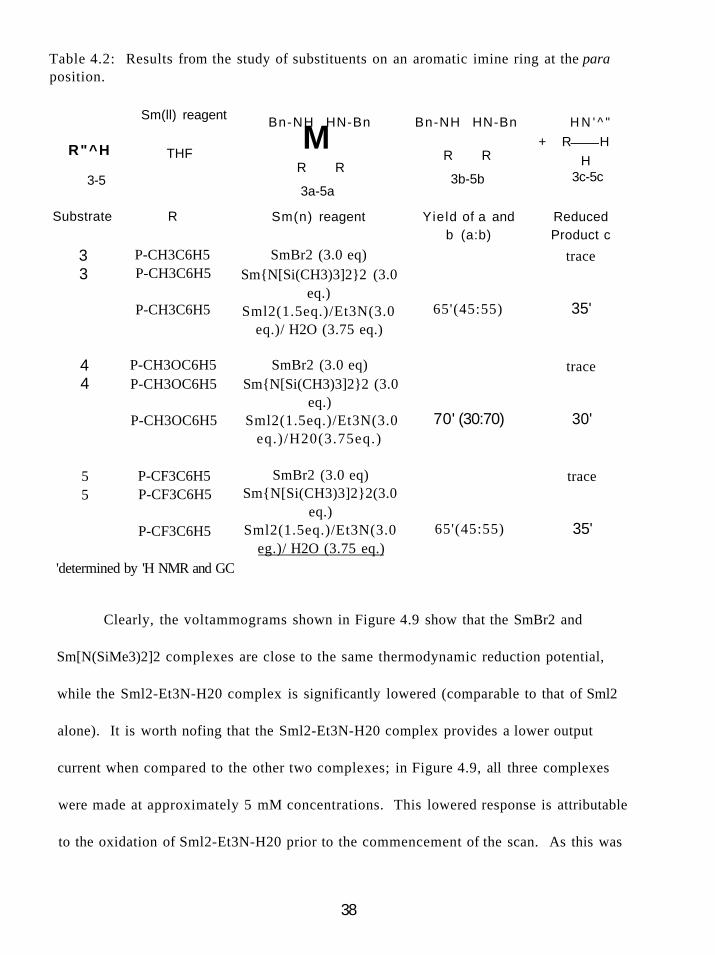
Table 4.2: Results from the study of substituents on an aromatic imine ring at the para position.
R"^H
3-5
Substrate
Sm(ll) reagent
THF
R
Bn-NH HN-Bn
M R R
3a-5a
Sm(n) reagent
Bn-NH HN-Bn
R R
3b-5b
Yield of a and b (a:b)
H N ' ^ "
+ R H H
3c-5c
Reduced Product c
3 3
P-CH3C6H5 P-CH3C6H5
P-CH3C6H5
SmBr2 (3.0 eq) Sm{N[Si(CH3)3]2}2 (3.0
eq.) Sml2(1.5eq.)/Et3N(3.0
eq.)/ H2O (3.75 eq.)
65'(45:55)
4 4
P-CH3OC6H5 SmBr2 (3.0 eq) P-CH3OC6H5 Sm{N[Si(CH3)3]2}2 (3.0
eq.) P-CH3OC6H5 Sml2(1.5eq.)/Et3N(3.0
eq.)/H20(3.75eq.) 70' (30:70)
5 5
P-CF3C6H5 P-CF3C6H5
P-CF3C6H5
'determined by 'H NMR and GC
SmBr2 (3.0 eq) Sm{N[Si(CH3)3]2}2(3.0
eq.) Sml2(1.5eq.)/Et3N(3.0
eg.)/ H2O (3.75 eq.)
trace
35'
trace
30'
trace
65'(45:55) 35'
Clearly, the voltammograms shown in Figure 4.9 show that the SmBr2 and
Sm[N(SiMe3)2]2 complexes are close to the same thermodynamic reduction potential,
while the Sml2-Et3N-H20 complex is significantly lowered (comparable to that of Sml2
alone). It is worth nofing that the Sml2-Et3N-H20 complex provides a lower output
current when compared to the other two complexes; in Figure 4.9, all three complexes
were made at approximately 5 mM concentrations. This lowered response is attributable
to the oxidation of Sml2-Et3N-H20 prior to the commencement of the scan. As this was
38
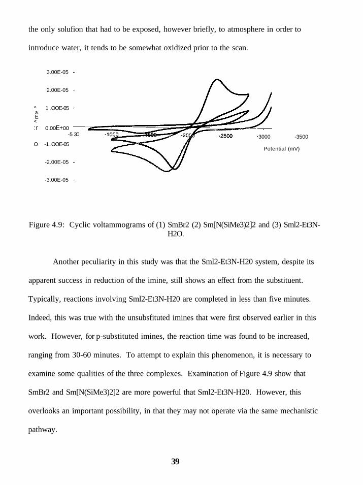
the only solufion that had to be exposed, however briefly, to atmosphere in order to
introduce water, it tends to be somewhat oxidized prior to the scan.
3.00E-05
2.00E-05
^ 1 .OOE-05 a. E < :r o.ooE+oo
O -1 .OOE-05
-2.00E-05
-3.00E-05
-5 30 3000 -3500
Potential (mV)
Figure 4.9: Cyclic voltammograms of (1) SmBr2 (2) Sm[N(SiMe3)2]2 and (3) Sml2-Et3N-H2O.
Another peculiarity in this study was that the Sml2-Et3N-H20 system, despite its
apparent success in reduction of the imine, still shows an effect from the substituent.
Typically, reactions involving Sml2-Et3N-H20 are completed in less than five minutes.
Indeed, this was true with the unsubsfituted imines that were first observed earlier in this
work. However, for p-substituted imines, the reaction time was found to be increased,
ranging from 30-60 minutes. To attempt to explain this phenomenon, it is necessary to
examine some qualities of the three complexes. Examination of Figure 4.9 show that
SmBr2 and Sm[N(SiMe3)2]2 are more powerful that Sml2-Et3N-H20. However, this
overlooks an important possibility, in that they may not operate via the same mechanistic
pathway.
39
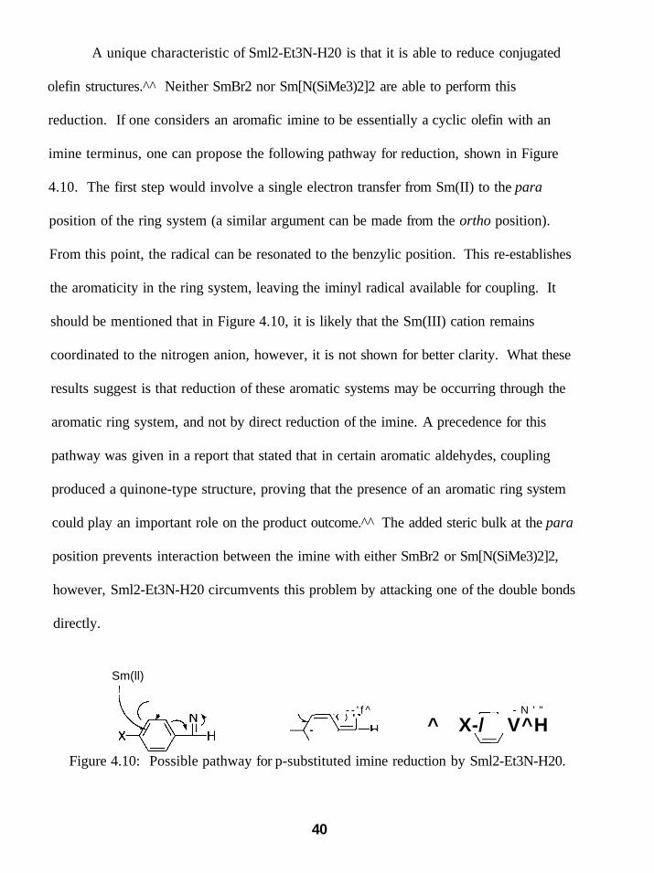
A unique characteristic of Sml2-Et3N-H20 is that it is able to reduce conjugated
olefin structures.^^ Neither SmBr2 nor Sm[N(SiMe3)2]2 are able to perform this
reduction. If one considers an aromafic imine to be essentially a cyclic olefin with an
imine terminus, one can propose the following pathway for reduction, shown in Figure
4.10. The first step would involve a single electron transfer from Sm(II) to the para
position of the ring system (a similar argument can be made from the ortho position).
From this point, the radical can be resonated to the benzylic position. This re-establishes
the aromaticity in the ring system, leaving the iminyl radical available for coupling. It
should be mentioned that in Figure 4.10, it is likely that the Sm(III) cation remains
coordinated to the nitrogen anion, however, it is not shown for better clarity. What these
results suggest is that reduction of these aromatic systems may be occurring through the
aromatic ring system, and not by direct reduction of the imine. A precedence for this
pathway was given in a report that stated that in certain aromatic aldehydes, coupling
produced a quinone-type structure, proving that the presence of an aromatic ring system
could play an important role on the product outcome.^^ The added steric bulk at the para
position prevents interaction between the imine with either SmBr2 or Sm[N(SiMe3)2]2,
however, Sml2-Et3N-H20 circumvents this problem by attacking one of the double bonds
directly.
Sm(ll)
^ X-/ V^H - - ' f ^ - N ' "
Figure 4.10: Possible pathway for p-substituted imine reduction by Sml2-Et3N-H20.
40

In light of this finding, we decided that we could provide some evidence for or
against this argument by shifting the location of the ring substituent to the meta position.
At this position, it is still unlikely for chelation to occur, but now the para position is
accessible for electron transfer. Results from this experiment are shown as Table 4.3.
Table 4.3: Results from reduction of meto-substituted aromatic imine.
N
R - ^ H
6
Bn Sm(ll) reagent
THF
Bn-NH HN-Bn
M R R
Bn-NH HN-Bn HN' + H-
6a
R R
6b
-Bn
-R H
6c Substrate R Sm(n) reagent Yield of a and
b (a:b) Reduced Product c
6 m-CHsCeHs SmBr2 (3.0 eq) 6 m-CH3C6H5 Sm{N[Si(CH3)3]2}2 (3.0
eq.) 6 m-CHaCeHs Smt (1.5 eq.)/Et3N (3.0
eq.)/H20(3.75eq.)
20° (44:56) 70'(15:85)
75' (46:54)
70 ^ trace
trace
isolated yield "determined by 'H NMR and GC
The results of this experiment are consistent with the previous explanation. Once
the hindrance at the para position is removed, all three reductants proved capable of
reducing the imine structure. Consistent with the unsubstituted aromatic imine cases,
only the Sm[N(SiMe3)2]2 reagent shows any significant stereoselective preference, with
the preference again being for the anti isomer. The one surprise was that SmBr2 proved
very effective at producing the reduction product, but showed very little of the radical
coupling product. Two possible explanations for this unusual behavior can be given.
The first explanafion could be that since SniBr2 is the apparentiy strongest reducing agent
41
(albeit by a small amount over Sm[N(SiMe3)2]2), it is a strong enough reductant to further
reduce the iminyl radical to an anion, halfing the coupling process. However, this
explanation does not seem reasonable when we examine the results from unsubstituted
aromatic imines, wherein SmBr2 does not show an excess of reduction product. Another
explanation concerns the relative sterics of these substrates. The addition of a m-methyl
should not restrict access to the imine for the first electron transfer, forming the iminyl
radical. However, after studying a model of this iminyl radical, it appears that there
could be some influence from the m-methyl and the benzyl group attached to the nitrogen
atom. To alleviate this strain, the benzyl group must rotate away from the methyl group.
This results in a shielding of the radical by the rest of the substrate to a greater degree
than the case when the substrate is unsubstituted. In the unsubstituted case, there seems
to be little in the way of barriers from sterics. This shielding of the radical decreases the
opportunity for radical-radical coupling, and in fact should be magnified because for
coupling to occur, both radicals (one from each porfion of the bimolecular process) must
be accessible simultaneously. Ultimately, this causes the radical to exist in solution for a
comparatively longer time than in the unsubstituted case, consistent with the reaction
times observed (reactions times were intermediate between the unsubstituted and para
substituted). During this prolonged time, a second electron transfer from SmBr2 may be
occurring. This begs the question of why this effect is only observed for SmBr2 and not
for the other two reagents. It is our supposition that this is due to the decreased size of
the SmBr2 reagent compared to the other two reagents. This would allow for a greater
42

probability for a second SmBrj molecule to access the iminyl radical through the
substrate shielding and transfer the second electron.
The investigation then turned toward the reactivity of ketimines. It should be
apparent that there is increased steric congestion at the carbon where coupling normally
occurs. Looking at Table 4.4, it is of littie surprise that the reduction product is favored
for both SmBr2 and Sm[N(SiMe3)2]2. What was worth noticing is that the Sml2-Et3N-
H2O reagent successfully couples this substrate. This can again be explained by
combining two previous arguments. First, assume that the first electron transfer occurs
through the aromatic ring. This negates the increased steric bulk about the initial imine
bond. This gives a benzyl radical surrounded by substrate skeleton. Keeping in mind
that this radical is stabilized by the aromatic ring system, the increased reduction
potential of SmBr2 and Sm[N(SiMe3)2]2 allows those reagents to reduce the radical to an
anion at a rate faster than Sml2, removing the radical from solution before bimolecular
radical coupling can occur. In this manner, we observe a larger amount of reduction
product for SmBr2 and Sm[N(SiMe3)2]2 than for the Sml2-Et3N-H20 reagent.
Table 4.4: Results from reduction of aromatic ketimines.
Bn Sm(ll) reagent Q^_^^ ^ ^ . g ^ gn-NH HN-Bn H N ' ^ " 1 »- _ * » _ _ * ^ _
-CH, n " H3C ) ( CH3 + H3C ) ( CH3 + Ph P h ^ C H 3 THF Ph' Ph Ph Ph H
7 Sm(n) reagent
7a Yieldof7aand7b(7a:7b)
7b 7c Reduced Product 7c
SmBr2 (3.0 eq) quantitative Sm{N[Si(CH3)3]2}2 (3.0 eq.) quantitative Sml2 (1.5 eq.)/Et3N (3.0 eq.)/ 80 (50:50) 20
H2O (3.75 eq.)
43
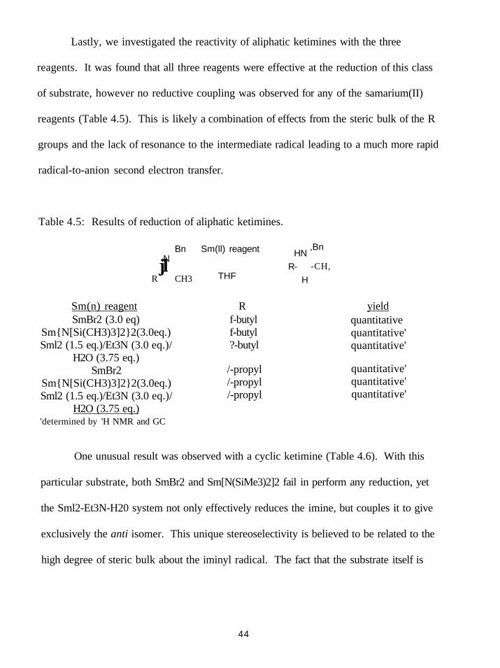
Lastly, we investigated the reactivity of aliphatic ketimines with the three
reagents. It was found that all three reagents were effective at the reduction of this class
of substrate, however no reductive coupling was observed for any of the samarium(II)
reagents (Table 4.5). This is likely a combination of effects from the steric bulk of the R
groups and the lack of resonance to the intermediate radical leading to a much more rapid
radical-to-anion second electron transfer.
Table 4.5: Results of reduction of aliphatic ketimines.
Bn Sm(ll) reagent N jl
R CH3
HN R-
THF
,Bn
-CH,
H
Sm(n) reagent R yield SmBr2 (3.0 eq)
Sm{N[Si(CH3)3]2}2(3.0eq.) Sml2 (1.5 eq.)/Et3N (3.0 eq.)/
H2O (3.75 eq.) SmBr2
Sm{N[Si(CH3)3]2}2(3.0eq.) Sml2 (1.5 eq.)/Et3N (3.0 eq.)/
H2O (3.75 eq.) 'determined by 'H NMR and GC
f-butyl f-butyl ?-butyl
/-propyl /-propyl /-propyl
quantitative quantitative' quantitative'
quantitative' quantitative' quantitative'
One unusual result was observed with a cyclic ketimine (Table 4.6). With this
particular substrate, both SmBr2 and Sm[N(SiMe3)2]2 fail in perform any reduction, yet
the Sml2-Et3N-H20 system not only effectively reduces the imine, but couples it to give
exclusively the anti isomer. This unique stereoselectivity is believed to be related to the
high degree of steric bulk about the iminyl radical. The fact that the substrate itself is
44

resonance stabilized by the phenyl ring allows the radical to be stable in solution for a
long enough period of time for coupling to occur.
Table 4.6: Results of reduction of cyclic ketimine.
^ "ph
Sm(n) reagent SmBrz (3.0 eq)
Sm{N[Si(CH3)3]2}2(3.0eq.) SmL (1.5 ea.)/Et,N (3.0 eq.VH,0 (3.75
i r
eq.)
^ N H
Pfi
yield' NR NR
90%(anr/)" "Determined by mass balance ''Determined by COSY NMR
4.4 Application of Sonochemistry to Sml2-Imine Reactions
At this point, our group was looking into methods for one-step synthesis of these
samarium(II) reagents (recall that for reagents with iodide replaced by some other ligand,
it was accomplished by addition of a lithium salt, this leaves Li I in solution). Attempts
were made using ultrasound application to mixtures of Sm(0) metal and H-N[Si(CH3)3]2
in hopes of making the Sm[N(SiMe3)2]2 species directly. Unfortunately, this experiment
failed. However, the experiment did cause our group to consider use of ultrasound as a
method for imine reduction utilizing simple Sml2.
The field of sonochemistry relates to the application of ultrasound to a chemical
system. Ultrasound frequencies (frequencies above 16 kHz) cause the formation of
microbubbles in the chemical medium. There are two differing theories concerning the
role of these bubbles in the mechanism of sonochemistry. One theory claims that as the
bubbles cavitate (collapse), large, localized amounts of pressure (up to 500 atm) and
45
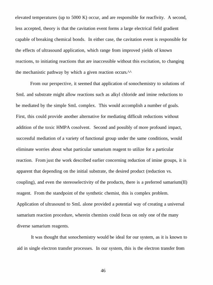
elevated temperatures (up to 5000 K) occur, and are responsible for reacfivity. A second,
less accepted, theory is that the cavitation event forms a large electrical field gradient
capable of breaking chemical bonds. In either case, the cavitation event is responsible for
the effects of ultrasound application, which range from improved yields of known
reactions, to initiating reactions that are inaccessible without this excitation, to changing
the mechanistic pathway by which a given reaction occurs.^^
From our perspective, it seemed that application of sonochemistry to solutions of
SmL and substrate might allow reactions such as alkyl chloride and imine reductions to
be mediated by the simple SmL complex. This would accomplish a number of goals.
First, this could provide another alternative for mediating difficult reductions without
addition of the toxic HMPA cosolvent. Second and possibly of more profound impact,
successful mediation of a variety of functional group under the same conditions, would
eliminate worries about what particular samarium reagent to utilize for a particular
reaction. From just the work described earlier concerning reduction of imine groups, it is
apparent that depending on the initial substrate, the desired product (reduction vs.
coupling), and even the stereoselectivity of the products, there is a preferred samarium(II)
reagent. From the standpoint of the synthetic chemist, this is complex problem.
Application of ultrasound to SmL alone provided a potential way of creating a universal
samarium reaction procedure, wherein chemists could focus on only one of the many
diverse samarium reagents.
It was thought that sonochemistry would be ideal for our system, as it is known to
aid in single electron transfer processes. In our system, this is the electron transfer from
46

Sm(n) to the substrate. One example of this is from Bremner in 1986, who found that a
methoxyaminosilane was initiated by ultrasound frequencies, giving quantitative yields of
product, illustrated in Figure 4.11 . ^
/ T ^ OCH3 LiAIH4 f-^ H \ ^ > - S i - C H 3 ^ ^ > -S i -CH3
O I ultrasound O ' , ^ n 3 OH3
Figure 4.11: Application of ultrasound to initiate the reduction of a methoxyaminosilane.
Ultrasound is also known to accelerate otherwise sluggish reactions. A number of
Diels-Alder cyclizations (a slow organic reaction) were shown by laved in 1995 to have
the rate of reaction significantly enhanced, while simultaneously increasing the overall
product yield, shown in Figure 4.12.^°
OCH,
CI'
without ultrasound: 35.0 hrs., 77.9% with ultrasound: 3.5 hrs., 97.3%
Figure 4.12: Application of ultrasound to accelerate a Diels-Alder reaction.
We began our study by reexamination of imine reduction, but now utilizing only
Sml2 instead of SmBr2, Sm[N(SiMe3)2]2, or Sml2-Et3N-H20. Results from this first study
are summarized as Table 4.7.
47

Table 4.7: Results of SmL mediated reducfion of imines with applied ultrasound.
Substrate % Yield (total products) Reduction Coupling (svn:anti)
N ^ / /
1 / V J L H
N \\ // H3CO^/ V - L H
. . N V \
80 16 84 (51 :49)
80 10 90 (25 :75)
85 60 40 (54:46)
H3C- / \ - ^ ^
75 14 86 (57 :43)
80 61 39 (43 : 57)
These results showed great promise for this technique, as we observed not only
reduction of the simple aldimines and ketimines, but also reduction of the para-
substituted aldimines that were so problematic previously. Blank experiments (lacking
samarium(II) reagent) recovered only unreacted starting material, proving the necessity
of the reducing agent. This was an important discovery, as this reaction could be
proposed as a radical coupling initiated by ultrasound, where the resultant nitrogen
radicals could then abstiact hydrogen atoms from the THF solvent. This explanation
48
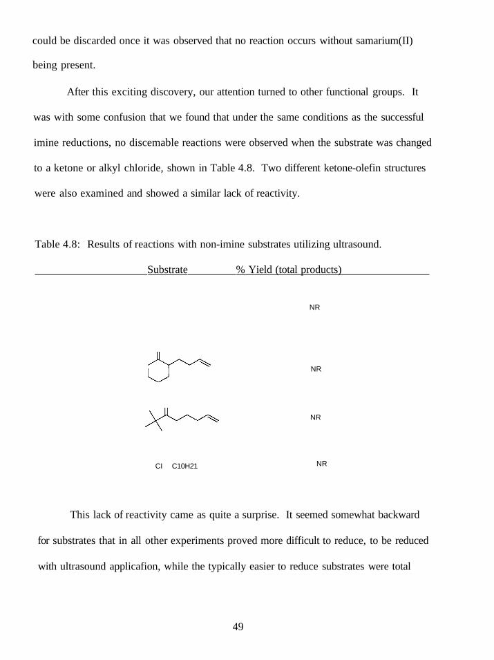
could be discarded once it was observed that no reaction occurs without samarium(II)
being present.
After this exciting discovery, our attention turned to other functional groups. It
was with some confusion that we found that under the same conditions as the successful
imine reductions, no discemable reactions were observed when the substrate was changed
to a ketone or alkyl chloride, shown in Table 4.8. Two different ketone-olefin structures
were also examined and showed a similar lack of reactivity.
Table 4.8: Results of reactions with non-imine substrates utilizing ultrasound.
Substrate % Yield (total products)
NR
CI C10H21
NR
NR
NR
This lack of reactivity came as quite a surprise. It seemed somewhat backward
for substrates that in all other experiments proved more difficult to reduce, to be reduced
with ultrasound applicafion, while the typically easier to reduce substrates were total
49

failures. Our hypothesis for this unusual behavior is as follows. After contacting the
manufacturer of the ultrasound equipment we were utilizing (VC-601 VibraCell), it was
discovered that we were operating at a fixed frequency of 20kHz. It would seem that this
is a frequency capable of activating the imine bond. We reasoned that if the SmL itself
was activated, we should have observed reduction for the typically easier to reduce
ketone substrates (these are reducible with inactivated SmL). It is known in the literature
that the operational frequency can have a profound impact on a given reaction. For
example, Koda reported in 2001 that the polymerization of styrene was inhibited as the
applied frequency changed from 23.4 kHz to 1 MHz. In fact, after reaching 518 kHz, this
polymerization reaction was nonexistent.^' Another example was provided by Kruss in
1997 who observed that the rate of chloride formation from a decomposition of
chlorobenzene was magnified at 900 kHz compared to that at 20 kHz. ^ These examples
are just a few that clearly show that the applied ultrasound frequency can be related to the
rate of reaction of the functional group involved. It is likely that the effects of frequency
change upon the microbubble cavitation event cause this rate enhancement. However,
these effects (heat and pressure during cavitation, microbubble size and rate of collapse,
etc.) are difficult to separate from one another experimentally. This creates a problem in
identifying the effect that is directiy related to the rate alteration.
Through fortuitous circumstances, our investigations began with a functional
group that could be reduced at our only available operational frequency. As it stands
currently, this study shows a unique method to selectively reduce an imine in the
presence of other typically easier to reduce groups by application of 20 kHz ultrasound.
50

Further studies should pursue the effect of frequency changes upon the rate of reaction
for these substrates.
51

CHAPTER 5
PHOTOCHEMISTRY OF SAMARIUM(II) REAGENTS
5.1 Introduction to Photochemistry
Photochemistry has an important role in chemistry. Life on Earth itself revolves
around this branch of chemistry through green plants, which utilize sunlight in the
photosynthesis process. The reaction of photosynthesis can be written concisely as
equation 5.1.
6CO2 + 6H2O P^°^°^y"^hesis (^H^Qj^ ^ gQ^ (5 .,j
This reaction is mediated by specialized organelles termed chloroplasts. Green
plants rely primarily on chlorophyll a, while bacteria utilize bacteriochlorophyll as the
light absorbing pigment. These pigments contain antennae that perform the initial
absorption and subsequent energy transfer.^^ The process is somewhat complicated;
however, it is a vital mechanism to the well being of life on Earth!
Many other photochemical reactions are known. Leigh and Postigo published a
report in 1995 where 1-phenylcyclobutene (and various aryl derivatives) performed a ring
opening when irradiated with light in acetonitrile solution, but instead performs a solvent
addition in methanol (Figure 5.1).
52
P - hv
Ph ^ Ph MeCN.
Ph \ ou Ph MeOH \ Ph^
Ph-OMe / \
Ph OMe Figure 5.1: Photochemistry of phenylcyclobutene in acetonitrile and methanol solvents.
The latter reaction (solvent addition) was found to occur in a Markovnikov
fashion, and is based from the first singlet excited state of the molecule. Evidence for
this statement was provided from decreased fluorescence quantum yields (compared to
that in acetonitrile), and a lack of quenching from addifion of dienes.
A number of metals can play a role in photoinitiated chemistry. This particular
aspect of photochemistry has been explored extensively in solar technologies.
Ruthenium(n) complexes are prevalent in this field, as they typically have high thermal
and photochemical stability, moderate to strong absorption of visible light, and are able to
perform both reductive and oxidation electron transfer chemistry. One example of this
was shown in 2001 by Kamat and Ghosh, who showed that Ru(bpy)3 " was readily
oxidized to Ru(bpy)3 ' in concentrated sulfuric acid when illuminated with unfiltered
sunlight. The reduced product from this was shown to be hydrogen peroxide. They
proposed a mechanism that explained the photochemistry involved (Figure 5.2).
53

Ru(bpy)3^^ + hv ==> *Ru(bpy)3^* (a)
*Ru(bpy)3^* + O2 ==> Ru(bpy)3^^ + O2" (b)
Ru(bpy)3^^ + O2" ==> Ru(bpy)3^^ -1- O2 (c)
Ru(bpy)3^^ + O2" + H^ ==> Ru(bpy)3^^ + HOz' (d)
*Ru(bpy)3^* -I- HOz" ==> Ru(bpy)3^^ + HO2" (e)
HO2 -I- H^ ==> H2O2 (f)
2 H02' ==> H2O2 + O2 (g)
2 Ru(bpy)3^* -t- H2O2 ==> 2 Ru(bpy)3^^ -h O2 + 2H* (h)
Figure 5.2: Scheme for photochemistry of Ru(n) in acidic media.
The first step is the excitafion of Ru(bpy)3 ' to generate *Ru(bpy)3"' (line a). This
excited cafion can then be oxidized by molecular oxygen to form Ru(bpy)3 ' and O2
(line b). Naturally, the reverse reaction can occur (line c), causing the net result to be a
quenching of the initial excited state species. However, should this quenching not occur,
Ru(bpy)3 " can react with O2" and a proton to form the HO2 radical (line d). This radical
can be further reduced to an anion by a second molecule of excited Ru(bpy)3~^ (line e).
The HO2" species can also accept a proton to create H2O2 (line f). Hydrogen peroxide can
also be formed from the disproportionafion of two HO2 radicals (line g). Finally,
hydrogen peroxide can reduce two Ru(bpy)3 ' molecules, bringing the system back to
starting material Ru(bpy)3^"^ (line h). This work illustrates the potential for transforming
light energies into chemical species of appreciable lifetimes.
Most researchers in photochemistry do certain experiments, and the previously
mentioned works are of no exception. These experiments typically include UV-Visible
54
spectioscopy, fluorescence/phosphorescence spectroscopy, determination of quantum
yields, and quenching studies. Some explanation of the impact of each of these
experiments is needed to provide understanding for our work.
UV-Visible spectroscopy is a method to monitor the amount of light absorbed by
a chemical species as a function of wavelength. This corresponds chemically to the
promotion of an electron from a vibrational level of the ground state to a vibrational level
of an excited state (HOMO to LUMO transition). This technique allows each species to
be identified by its characteristic absorpfion bands. By varying the concentration of
absorbing species in solufion, a Beer's Law plot can be derived. For Beer's plots of
linear nature, the slope is equal to the molar extinction coefficient. This provides a
numerical value that is directly related to the efficiency of the chemical species at
absorbing light. To illustrate why this value could be of potential interest, examine the
following argument. Suppose two different metal complexes promote the same reaction
after photochemical initiation. The product distributions after the reaction are equivalent,
costs of both chemicals are equal, and there is no appreciable other difference in the two
metal complexes except that one has a molar extinction coefficient of 10,000 Lmole
cm"' and the second complex has a coefficient of only 10 L mole"' cm"'. Clearly, the first
complex is more efficient at absorbing light, making it the preferable reagent.
Fluorescence and phosphorescence spectroscopies are a complement to UV-
Visible spectroscopy. While UV-Visible spectroscopy measures the energy needed to
promote an electron to the excited state, these techniques measure the release of energy
from the excited state back to the ground state. The fundamental difference between the
55
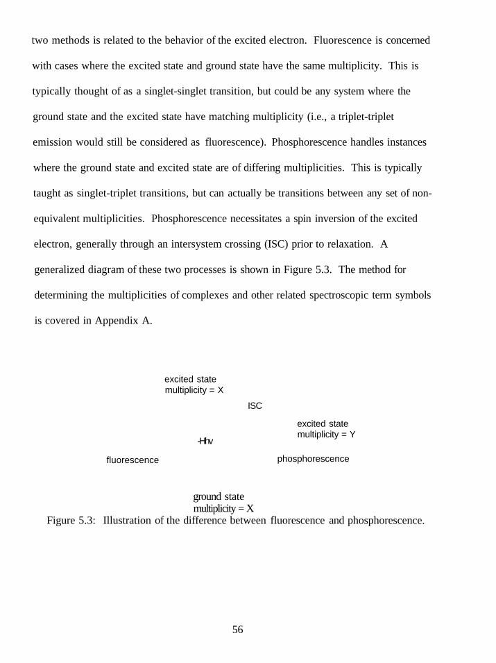
two methods is related to the behavior of the excited electron. Fluorescence is concerned
with cases where the excited state and ground state have the same multiplicity. This is
typically thought of as a singlet-singlet transition, but could be any system where the
ground state and the excited state have matching multiplicity (i.e., a triplet-triplet
emission would still be considered as fluorescence). Phosphorescence handles instances
where the ground state and excited state are of differing multiplicities. This is typically
taught as singlet-triplet transitions, but can actually be transitions between any set of non-
equivalent multiplicities. Phosphorescence necessitates a spin inversion of the excited
electron, generally through an intersystem crossing (ISC) prior to relaxation. A
generalized diagram of these two processes is shown in Figure 5.3. The method for
determining the multiplicities of complexes and other related spectroscopic term symbols
is covered in Appendix A.
excited state multiplicity = X
fluorescence
ISC
-Hhv
excited state multiplicity = Y
phosphorescence
ground state multiplicity = X
Figure 5.3: Illustration of the difference between fluorescence and phosphorescence.
56

ft is possible that a molecule that can absorb light does not release this energy by
either fluorescence or phosphorescence. Other deactivation processes include external
and internal conversions (loss of energy as heat), pre-dissociation (complex has bond
cleavage prior to excitation), and dissociation (complex has bond cleavage after
excitation). Quantum yields relate the fraction of a particular relaxation process to that of
the total deactivation processes. For example, the quantum yield of fluorescence of a
molecule is simply the fraction of molecules that fluoresce compared to the total number
of excited molecules. This relationship can be expressed though equation 5.2, where kf is
the rate of fluorescence, ki is the rate of intersystem crossing, kec is the rate of external
conversion, kic the rate of internal conversion, kpd is the rate of pre-dissociation, and kd is
the rate of dissociation.^^ Essentially, quantum yields are a measurement of the
efficiency of a particular deactivation process for a species.
Of = kf/(kf-i-ki-i-kec-i-kic-i-kpd-i-k<i) (5.2)
Quenching studies can be performed on species that exhibit fluorescence or
phosphorescence. After irradiation of an analyte in solution with a potential quencher, it
is expected that the emission of the excited species will show one of two outcomes; either
there will be no change in the spectrum, which implies that no photochemical process is
occurring, or the emission intensity will be reduced, which implies that the amount of
excited state species in solution has been reduced through a deactivation process related
57
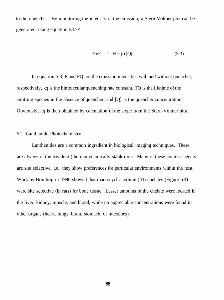
to the quencher. By monitoring the intensity of the emission, a Stern-Volmer plot can be
generated, using equation 5.3. "
Fo/F = 1 -H kqTo[Q] (5.3)
In equation 5.3, F and FQ are the emission intensities with and without quencher,
respectively, kq is the bimolecular quenching rate constant, TQ is the lifetime of the
emitting species in the absence of quencher, and [Q] is the quencher concentration.
Obviously, kq is then obtained by calculation of the slope from the Stern-Volmer plot.
5.2 Lanthanide Photochemistry
Lanthanides are a common ingredient in biological imaging techniques. These
are always of the trivalent (thermodynamically stable) ion. Many of these contrast agents
are site selective, i.e., they show preferences for particular environments within the host.
Work by Bomhop in 1996 showed that macrocyclic terbium(III) chelates (Figure 5.4)
were site selective (in rats) for bone tissue. Lesser amounts of the chelate were located in
the liver, kidney, muscle, and blood, while no appreciable concentrations were found in
other organs (heart, lungs, brain, stomach, or intestines).
58
o P" C4H9O \ _ ^ j Tb^. fi_y'^-OC4H9 "O3R
-N-
c^H^d o
N Tb^"" N ,PO 3
Figure 5.4: Terbium(III) chelates for medical imaging.
These terbium(III) chelates showed absorption maxima near 270 nm, and
fluoresced at 550 nm with quantum yields ranging from 0.21 to 0.48 (relative to
rhodamine 6G in ethanol). These values are very significant to their work, the large shift
from excitation to emission is claimed as a benefit to signal/noise ratio for detection, and
the sizable quantum yield for each chelate lessens the total amount of material needed for
detection. The reason for bone selectivity is attributed to ionic interactions between Ca ^
in the bone tissue and the phosphonic anion groups of the chelate.
Another example of photochemical utilization of lanthanides was published by
Sharipovin 1993. Their work showed that Ce " could be photochemically excited (313
nm using filters). This species could then decompose cyclic four-membered peroxides to
ketones (Figure 5.5). ^
59

R-R-
" -O ^ . c e ^ . . R--O R-
( g4+ ^ R ^ O - + R ^ O -
Ce"*
R
Figure 5.5: Photoinitiated oxidation of peroxides by Ce " .
They proposed that the first step in this process after cerium(III) excitation is the
reduction of the peroxide bond to form an radical anion and Ce(rV). The radical anion
decomposes into a diradical leading directly to one molecule of ketone. The other
decomposition product is a second radical anion. This is oxidized by Ce * to form
another diradical, leading to the second ketone molecule.
Of particular interest to our research was a report by Ogawa in 1997 that showed
that reduction of alkyl chlorides by SmL could be accelerated if illuminated with visible
light (Figure 5.6)."
hv > 300nm n-Ci2H25CI -h2.2Sml2 *- n-CigHje 88%
THF, 40°C
Figure 5.6: Reduction of alkyl chloride by excited SmL.
In Ogawa's work, use of cut off filters showed that only certain wavelengths of
ight initiated these reactions. Specifically, wavelengths between 500 and 800 nm gave
60

the highest yields of product. This wavelength range corresponds to two prominent
absorpfions for SmL. This work was of significance to our research since this particular
class of compounds (alkyl chlorides) cannot be effectively reduced by SmL in the ground
state. To promote this reaction with SmL as the reducing agent, HMPA must be added as
a cosolvent. Unfortunately, the toxicity of HMPA makes it very undesirable for synthetic
work. A long-standing research goal has been to develop methods for replacing HMPA
in samarium chemistry. Ogawa's work provides the first example of increasing the
reducing power of SmL through photochemistry.
5.3 Origin of Electronic Transitions in Lanthanides
The origin of transitions in lanthanide complexes is dependent on the nature of the
complex and the charge of the lanthanide cation. Many of the lanthanide(III) complexes
emit as a result of ligand excitation followed by ligand-to-metal energy transfer to the
lanthanide, followed by emission (Figure 5.7).
ligand, ' A *
excitation
ISC (2) (3)
ligand, ^A* Ln (3-H)*
(1) (4) emission
Ln (3+)
ligand, A
Figure 5.7: Schematic for Ln(III) electronic transitions.
61

This is explained in the following manner. The attached ligand is excited from
the ground state to an excited singlet state (1). An intersystem crossing from the excited
singlet state to a ligand based triplet state occurs (2). Energy transfer from this ligand
based triplet state to a metal based excited state, predominantiy f-orbital in nature, occurs
(3). Then the emission of this energy proceeds; returning the system to the ground state
(4). Excellent examples of this mechanism are given by Verhoeven and Reinhoudt for
both Eu(III) and Tb(III) complexes of tetraazatriphenylene derivatives, who showed that
the excitation spectrum of the complexes was identical to that of the absorption spectrum
of the free ligand, clearly showing that the emission energy came from ligand
excitation.'^
For divalent lanthanides, the mechanism occurs in a different fashion. While it is
well known that the 4f electrons are shielded from their environment, the act of excitation
ultimately results in the excited electron residing in the less shielded d-orbitals, which can
be affected by ligand environment. Dorenbos examined the divalent spectroscopy for the
entire series of lanthanides in the (II) oxidation state and arrived at the following
71
conclusions (Figure 5.8).
fd state
i
excitation
(1)
(2p \ dorb
(3)
1
emission
Ln(2+)
Figure 5.8: Dorenbos representation for divalent lanthanides.
62
In figure 5.8, an electron from the 4f orbitals is excited to an f-d state (1). This
state is characterized by mixed high spin (HS) and low spin (LS) energy levels, the ratio
of which (for the lowest energy level) is dependent on the exchange interaction between
the excited electron and the electrons remaining in the 4f orbitals. The excited electron
crosses into a lower energy 5d-orbital (2). From this 5d-orbital radiative emission can
occur (3). This emission can be characterized as fluorescence for certain lanthanides
(Gd, Ho, Er, Tm) where the 5d emission level has the same multiplicity as the ground
state, or as phosphorescence (Sm, Eu, Tb) when these multiplicities differ. This is an
important distinction that has seemingly been ignored, as numerous papers refer to
samarium(II) emissions as fluorescence instead of the correct term, phosphorescence. It
should also be noted that this excitation to the fd state a Laporte allowed transition.
5.4 Particulars of Samarium Spectroscopy
Samarium (II) contains a 41* ground state with a term symbol of FQ. The
absorption process excites an electron to an f-d level (from a decoupled scheme, the
lowest state are ^F and ^H). Relaxation through ISC causes the electron to enter a ^DQ
level from which phosphorescence occurs. The origin of these terms is described in the
following manner. In the initial ground state, 4f , there are six unpaired electrons. The
individual f-orbitals are labeled from 3 to -3 (numbering is arbitrary and has no
relationship to the actual identities of the individual f-orbitals), and one electron is
allocated to each of the six most positive values, 3 to -2 (Figure 5.9).
63
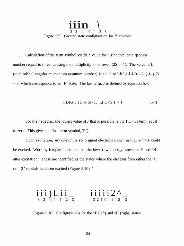
iiin \ 3 2 1 0 - 1 - 2 - 3
Figure 5.9: Ground state configurafion for f* species.
Calculafion of the term symbol yields a value for S (the total spin qantum
number) equal to three, causing the multiplicity to be seven (2S -i- 1). The value of L
(total orbital angular momentum quantum number) is equal to3-h2-i-l-i-0-i-(-l)-i- (-2)
= 3, which corresponds to an 'F' state. The last term, J is defined by equation 5.4.
I L-l-S I, I L -I- SI -1, ....I L - S I = J (5.4)
For the f species, the lowest value of J that is possible is the I L - SI term, equal
to zero. This gives the final term symbol, 'FQ.
Upon excitation, any one of the six original electrons shown in Figure 4.4.1 could
be excited. Work by Krupke illustrated that the lowest two energy states are F and ^H
after excitation. These are identified as the states where the electron from either the "0"
or "-2" orbitals has been excited (Figure 5.10).'^
i i i ) L i i _ i i i i i 2 ^ _ 3 2 1 0 - 1 - 2 - 3 3 2 1 0 - 1 - 2 - 3
Figure 5.10: Configurations for the ^F (left) and ^H (right) states.
64
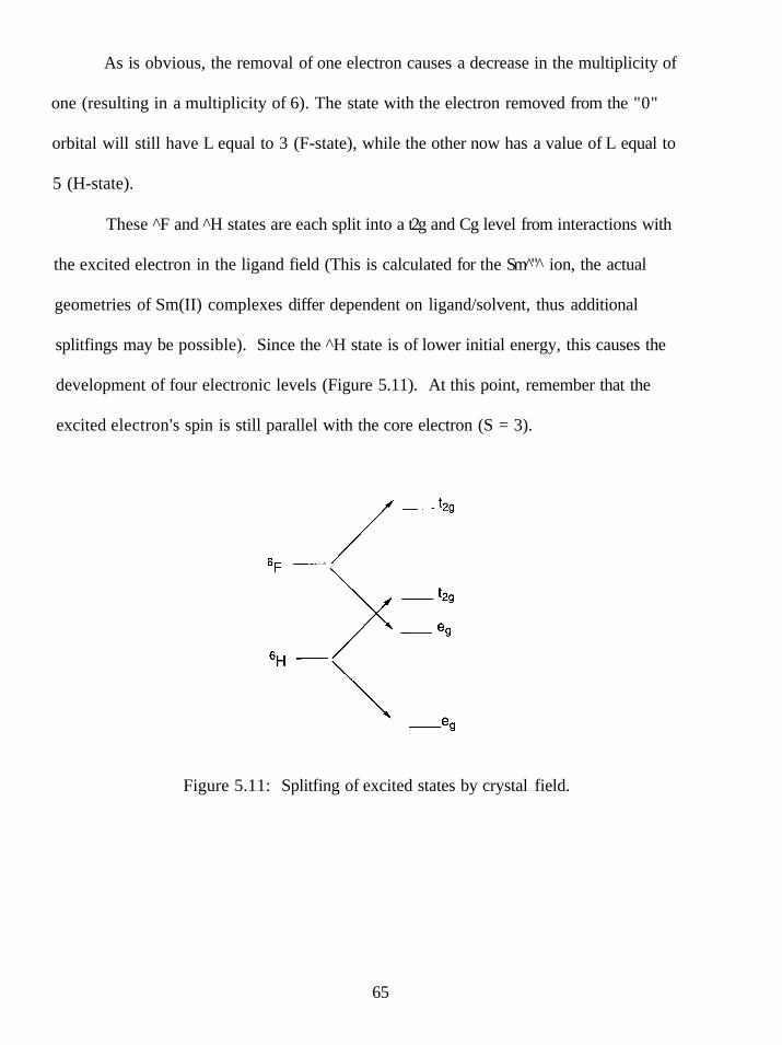
As is obvious, the removal of one electron causes a decrease in the multiplicity of
one (resulting in a multiplicity of 6). The state with the electron removed from the "0"
orbital will still have L equal to 3 (F-state), while the other now has a value of L equal to
5 (H-state).
These ^F and ^H states are each split into a t2g and Cg level from interactions with
the excited electron in the ligand field (This is calculated for the Sm " ion, the actual
geometries of Sm(II) complexes differ dependent on ligand/solvent, thus additional
splitfings may be possible). Since the ^H state is of lower initial energy, this causes the
development of four electronic levels (Figure 5.11). At this point, remember that the
excited electron's spin is still parallel with the core electron (S = 3).
Figure 5.11: Splitfing of excited states by crystal field.
65

There are now four levels for the excited electron to occupy, and this is reflected
in the four maxima observed for SmL. However, emission does not come from these
levels. Due to a significant exchange interaction between the excited electron and the
remaining core electrons, a spin inversion occurs. This results in the multiplicity for the
system decreasing from three to two. The four excited state levels are maintained, though
their individual energies are altered. Regardless of which of these levels the electron
occupies, it eventually decays to the lowest energy level, which is DQ. It is from this
level that emission occurs (Figure 5.12).
fd state, F, H
excitation
d orbital, ''DQ
phosphorescence
Sm(2+), ^Fo
Figure 5.12: Electronic transitions for the Sm(II) species.
5.5 UV-Vis Spectroscopy of Sm(II) Complexes
UV-Visible spectroscopy was the first set of experiments that were performed.
Four samarium(II) complexes were chosen as analytes; SmL, SmBr2, Sm[N(SiMe3)2]2,
and SmL-HMPA. While the spectra of each complex are moderately similar, there are
subtie differences in the spectra. Representative spectra are shown in Figure 5.13. some
66

-0,5 500
Wavelength (nm)
•SmBr2 Sml2 •Sml2-HMPA X Sm[N(Si(CH3)2)2]2
Figure 5.13: UV spectra of SmL, SmL-HMPA, SmBr2, and Sm[N(SiMe3)2]2.
First, it is evident that the SmL and SmBr2 spectra are virtually identical, with the
peak maxima for SmBr2 being slightiy blue-shifted (10-20 nm). The addition of HMPA
to SmL causes an apparent loss of one of the higher energy transitions (or overlap of the
two peaks) and also alters the peaks between 500-700 nm. For SmL (and SmBr^), there
are two peaks in this region with the higher energy transitions of each species being of
lesser intensity. After addition of HMPA, we observe that the higher energy transition is
now more prominent. Changing the ligand to the bis-trimethylsilyl anion shows an even
more profound impact. We now observe only a single transition between 500 and 700
nm. The results are consistent with what is known about the structures of the complexes.
SmL and SmBr2 are likely of similar structure, where the halide ligands are axial and
have solvent molecules about the equatorial positions. The SmL-HMPA complex is
known to have two different crystal structures, dependent on the amount of HMPA added
to the solution. With large amounts of HMPA (>10eq), the complex is octahedral, but
67

when lesser amounts of HMPA are ufilized (4-lOeq), the complex forms a distorted
octahedron with four HMPA molecules in a square planar conformation and the iodides
at axial positions. The Sm[N(SiMe3)2]2 complex is pseudo-tetrahedral, with the bis-
trimethylsilyl ligands occupying two sites, and solvent occupying the other two. It is
apparent that these structural changes are affecting the energetics of the d-orbitals the
excited electron is promoted to, resulting in the peak shifts observed.
5.6 SmL Absorbance Spectra and Spectroscopy
Beer's law plots of SmL were generated for concentrations between 4 x 10"'* M
and 2 x 10" M (Figure 5.14). All peak maxima show a linear relationship from Beer's
law. Slopes from this data were calculated as the molar extinction coefficients (Table
5.1).
^ 2.5
s < 2 o g 1.5 o (A .Q <
1
0.5
0.0005 0.001 0.0015
[SmlJ, M
• 351 nm
^ ^ L i n e a r (351 nm)
421 nm
•Linear (421 nm)
y=1326x
= 603.64X
R" = 0.9784
572.6X
0.9751
0.002 0.0025
558 nm
•Linear (618 nm)
618 nm 1 I
•Linear (558 nm)j
Figure 5.14: Beer's law plots for SmL.
68
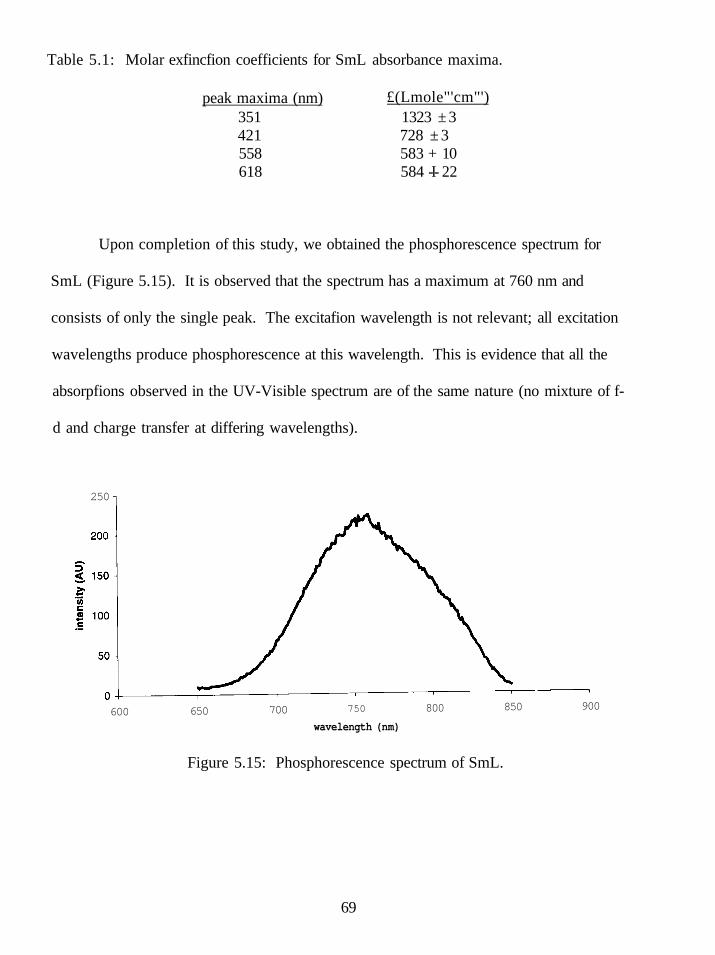
Table 5.1: Molar exfincfion coefficients for SmL absorbance maxima.
peak maxima (nm) £(Lmole"'cm"') 351 421 558 618
1323 ± 3 728 ± 3 583 + 10 584 -I- 22
Upon completion of this study, we obtained the phosphorescence spectrum for
SmL (Figure 5.15). It is observed that the spectrum has a maximum at 760 nm and
consists of only the single peak. The excitafion wavelength is not relevant; all excitation
wavelengths produce phosphorescence at this wavelength. This is evidence that all the
absorpfions observed in the UV-Visible spectrum are of the same nature (no mixture of f-
d and charge transfer at differing wavelengths).
250
600 650 700 750
wavelength (nm)
800 850 900
Figure 5.15: Phosphorescence spectrum of SmL.
69
Quantum yield calculafions were made to judge the efficiency of phosphorescence
for SmL. These experiments were performed utilizing Cu(dmp)2'' as a reference (O =
2.7 X 10 , CH2CI2 solvent). Equation 5.5 was utilized to compensate for differences in
the optical densities between SmL and standard.
Oa = Os [(TlaV(lls')] X [AJA,] X [(l-10-°''^)/(l-10"°'''^)] (5.5)
In equation 5.5, Oa is the quantum yield of the analyte, Os is the reported quantum
yield of the standard, rja and rjs are the refractive indices of the analyte solution and
standard solution, respectively, Aa and As are the integrated peak areas from the emission
of the analyte and standard solutions, and ODs and ODa are the optical densities of the
standard and analyte solutions at the excitation wavelength. "*
Utilizing equation 5.5 with the measured integrated emission intensities (Figure
5.16), a value of 0.13 was obtained as the relative quantum yield of phosphorescence for
SmL.
70

1000
800
600
in g 400
200
-200
600 650 700 750 800 850 900
Wavelength (nm)
Figure 5.16: Overlay of SmL (grey) and Cu(dmp)2'" (black) emission spectra.
The last sets of experiments performed were photochemical quenching studies.
It is necessary to begin with quencher molecules that do not coordinate or react with SmL
in the ground state. Five classes of substrate were selected from this criteria, aliphatic
ketones (aromatic ketones react in ground state), alkyl chlorides (iodides and bromides
are reduced in ground state), aromatic ketimines, nitriles, and alkenes.
For aliphatic ketones, 2-butanone was chosen as the quencher. A Stern-Volmer
plot of [Q] vs. IQ/I (Figure 5.17) showed a linear relationship. The slope of the line is
equal to kqXo. Using the known lifetime of SmL of 125 nsec, ^ the bimolecular quenching
rate is found to be 3.85 -i- 0.05 x 10 M"'sec"'.
71

1.4 1
1.3
1.2 -
5. 1.1
1 <
0.9
0.8 -
y = 4.7756X + 1
R^ = 0.9853
0 0.01 0.02 0.03 0.04 0.05 0.06 0.07 0.08
[Q],M
Figure 5.17: Stem Volmer plot for the quenching of SmL with 2-butanone.
For the quenching of SmL with an alkyl chloride, 1-chlorobutane was utilized as
the quencher. A Stern-Volmer plot of [Q] vs. IJl (Figure 5.18) showed a linear
relationship. After determination of the slope and then solving for the bimolecular rate
1 -1 constant, a value of 2.02 + 0.06 x 10 M" sec" was obtained
Figure 5.18: Stern-Volmer plot for quenching of SmL with 1-chlorobutane.
72

The N-benzyl imine derivative of acetophenone was used as the quencher for
aromatic imines. Again, the Stern-Volmer plot showed a linear relationship. After
determination of the slope and then solving for the bimolecular rate constant, a value of
2.15 + 1.45 X 10^ M''sec"' was obtained (Figure 5.19).
0.005 0.01 0.015
[Q], M
0.02 0.025
Figure 5.19: Stern-Volmer plot for quenching of SmL with aromatic imine.
p-Toludine was used as the representative quencher for nitriles. Again, the Stem-
Volmer plot showed a linear relationship. After determination of the slope and then
solving for the bimolecular rate constant, a value of 2.65 + 0.15 x 10 M"'sec"' was
obtained (Figure 5.20)
73
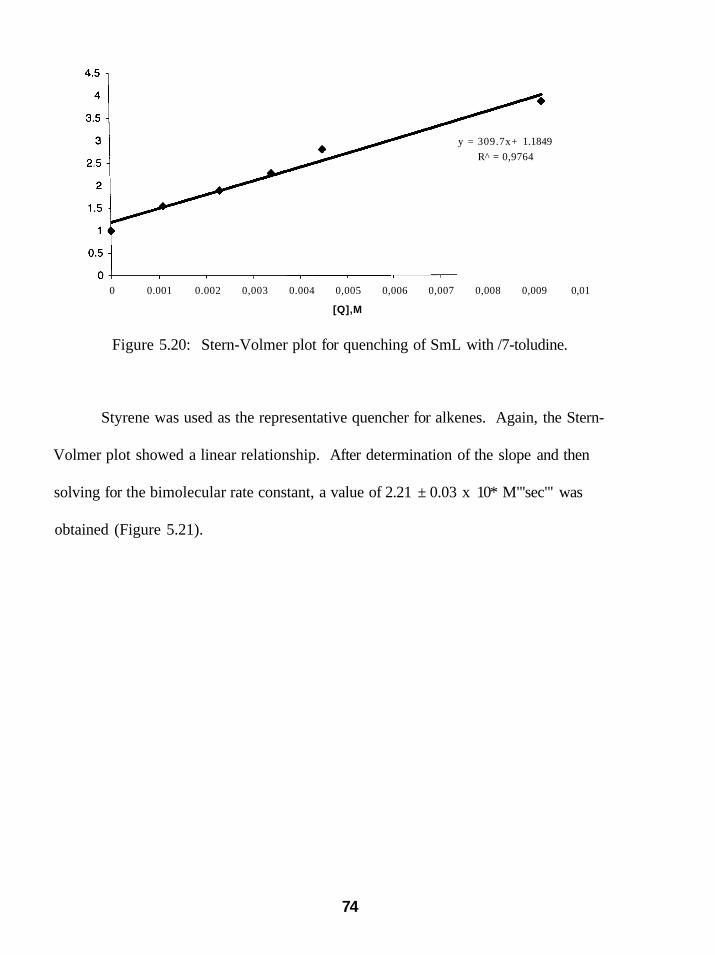
y = 309.7x+ 1.1849
R^ = 0,9764
0 0.001 0.002 0,003 0.004 0,005 0,006 0,007 0,008 0,009 0,01
[Q],M
Figure 5.20: Stern-Volmer plot for quenching of SmL with /7-toludine.
Styrene was used as the representative quencher for alkenes. Again, the Stern-
Volmer plot showed a linear relationship. After determination of the slope and then
solving for the bimolecular rate constant, a value of 2.21 ± 0.03 x 10* M"'sec"' was
obtained (Figure 5.21).
74

y = 27,894x + 1
0.005 0,01 0,015 0,02
[Q], M
0,025 0,03 0,035
Figure 5.21: Stern-Volmer plot for quenching of SmL with styrene.
The quenching rate constants were found to be in good agreement with calculated
rate constants from Marcus theory. From the literature, the reduction potentials of
primary chlorides are approximately -2.80V and ketones are at approximately -2.84V. '
The ketimine utilized in these experiments was found to have a reduction potential of
-2.50V.^* The nitrile and styrene have reduction potentials of -2.75 and -2.73V,
respectively.^^'*" These values can be utilized to calculate the free energy of electron
transfer through equation 5.6, where Eox is the potential of the oxidized species (SmL),
Ered the potential of the reduced species (quencher), Eo-o is the energy of the lowest
energy transition (found by the overlap between absorption and emission spectra), rp is
the radius of the probe (SmL) and rq is the radius of the quencher molecule as shown in
equation 5.6. This is known as the Weller equation.*' Table 5.2 gives the calculated free
energies of electron transfer.
75

AGo = Eox - Ered - Eo.o-[(e /(8od)) + (e^/2)(l/rp + l/rq)(l/37 - 1/7.6)] (5.6)
Table 5.2: Values used for calculation of the free energies of electron transfer.
Structure
II
Cr'OH, ^
o-HgC^J^^N
CI-C4H9
0
Er.H(V) T^(A) AG° (kcal/mole)
-1.90 4.6
-2.73 3.7
-2.75 3.7
-2.80 3.1
-2.84 2.8
-25.13
-19.28
•18.81
•17.09
-15.73
Once the free energies of electron transfer were found, Marcus theory could be
utilized to estimate the rate of electron transfer. The form of the Marcus equation utilized
is shown as Equation 5.7 82
ket — JCd. (5.7) 0 / - i x 2 s
1 + 0.2 exp[(^4) x[{\+ AG7 XY) IRT]
76
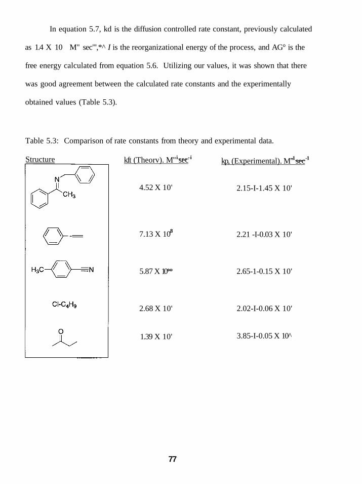
In equation 5.7, kd is the diffusion controlled rate constant, previously calculated
as 1.4 X 10 M" sec"',*^ I is the reorganizational energy of the process, and AG° is the
free energy calculated from equation 5.6. Utilizing our values, it was shown that there
was good agreement between the calculated rate constants and the experimentally
obtained values (Table 5.3).
Table 5.3: Comparison of rate constants from theory and experimental data.
Structure i„„„-i kft (Theorv). M" sec -1 -1
4.52 X 10'
,8 7.13 X 10
5.87 X 10**
2.68 X 10'
1.39 X 10'
kp, (Experimental). M" sec
2.15-I-1.45 X 10'
2.21 -I-0.03 X 10'
2.65-1-0.15 X 10'
2.02-I-0.06 X 10'
3.85-I-0.05 X 10
77

5.7 SmBr2 Absorbance Spectra and Spectroscopy
The UV-Visible spectrum of SmBr2 is quite similar to that of SmL- There is a
slight blue shift for each peak maximum (ranging from about 10-20 nm), signifying that
the transitions involved are all of slightiy higher energy than that of Sml2. Beer's Law
plots were made utilizing concentrations between 2x10"^ and 5x10"'' M. These plots
showed a linear relationship in this concentration range (Figure 5.22). The molar
extinction coefficients were calculated from the slopes of the best linear fit through the
plots (Table 5.4).
0) o c a ja o (0 .a <
3 1
2,5
2 -
1,5
1 •
0,5
0.0005 0.001 0,0015 [SmBrj], M
• 339 nm
^^ Linear (339 nm)
y = 791,8x•^0.89
R^ = 0,9888
= 740.4X + 0,8675 R^ = 0.9892
= 523.6X + 0,5555
R^ = 0.9911
= 505,4x + 0,5745
R^ = 0,9928
0,002 0,0025
405 nm 543 nm 597 nm
•Linear (405 nm) Linear (543 nm) Linear (597 nm)
Figure 5.22: Beer's Law plots for SmBr2.
Table 5.4: Molar extincfion coefficients for SmBr2 peak maxima.
peak maxima (nm) 339 405 543 597
s (L mole'cm"') 802 ± 10 755 ±15 534 ± 11 517-h 12
78
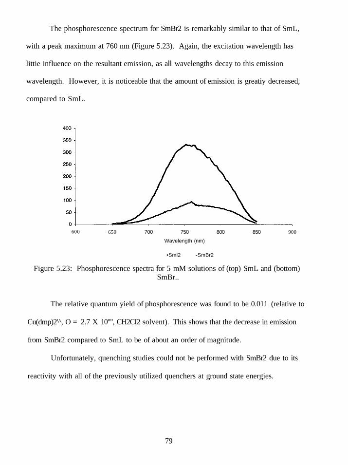
The phosphorescence spectrum for SmBr2 is remarkably similar to that of SmL,
with a peak maximum at 760 nm (Figure 5.23). Again, the excitation wavelength has
littie influence on the resultant emission, as all wavelengths decay to this emission
wavelength. However, it is noticeable that the amount of emission is greatiy decreased,
compared to SmL.
600 650 700 750
Wavelength (nm)
800 850 900
•Sml2 -SmBr2
Figure 5.23: Phosphorescence spectra for 5 mM solutions of (top) SmL and (bottom) SmBr..
The relative quantum yield of phosphorescence was found to be 0.011 (relative to
Cu(dmp)2' , O = 2.7 X 10"", CH2CI2 solvent). This shows that the decrease in emission
from SmBr2 compared to SmL to be of about an order of magnitude.
Unfortunately, quenching studies could not be performed with SmBr2 due to its
reactivity with all of the previously utilized quenchers at ground state energies.
79

One could conclude that SmBr2 has no apparent advantage for photochemistry
over SmL alone. The efficiencies of absorpfion and emission are both decreased, and the
general reactivity in the ground state prevents dynamic quenching to be performed.
5.8 Sm[N(SiMe3)2]2 Spectra
Beer's Law plots for this complex showed a linear relationship at concentrations
from 2 xlO"^ to 4 x 10" M (Figure 5.24). Slopes from the linear plots are expressed as
the molar extinction coefficients (Table 5.5).
2.5
<u o c n .a o lA
<
1.5
0,5
0 0,0015
y = 641,86x-0,5772
9385
7x-1,0101 9934
0,002 0,0025 0.003 0.0035
[Sm[N(SiMe3)2]2, M
0.004 0,0045
• Seriesi Series2 •Linear (Series2) •Linear (Seriesi)
Figure 5.24: Beer's law plots of Sm[N(SiMe3)2]2
80

Table 5.5: Molar extinction coefficients for Sm[N(SiMe3)2]2-
peak maxima (nm) e (L mole"'cm') 385 539 ±68 562 426 + 54
It was found in the course of trying to obtain quantum yield values for this
complex that it does not show any emission. This could arise from two possibilities; one
is that the bent shape of this complex is allowing for an easier transfer of the excitation
energy to solvent molecules by virtue of having a more accessible metal center. The
other explanation is that the N(SiMe3)2 ligand acts as a quencher itself. This self-
quenching characteristic makes this complex unsuitable for photochemistry.
5.9 SmL-HMPA Spectra
Beer's Law plots were generated and showed a linear relationship between
concentrations of 1.0 x 10" and 2.5 x 10" "M (Figure 5.25). Slopes from these plots are
expressed as the molar extinction coefficients (Table 5.6).
81

2.5
< 2 oT u S 1.5
jQ w O (A
5 ' 0,5
0.0005 0.001 0.0015
[SmIj-HMPA], M
0.002
y = 1095x-0.254
R^ = 0,9659
= 769,4x - 0.2822
R^ = 0,9783
0,0025
• 379 nm 540 nm •Linear (379 nm) •Linear (540 nm)
Figure 5.25: Beer's law plots of SmL-HMPA.
0,003
Table 5.6: Molar extinction coefficients for SmL-HMPA.
peak maxima (nm) e (L mole"'cm') 379 540
1142 ±47 802 + 33
SmL-HMPA also shows a strong shoulder at 620 nm. A lesser shoulder appears
at 420 nm, making the spectrum look somewhat similar to that of SmL and SmBr2. The
two main peaks are not both blue shifted compared to SmL, as was observed for SmBr2.
The lower energy transition (540 nm) is blue shifted from SmL by 18 nm, but the higher
energy transition (379 nm) is actually red shifted by the same amount. Additionally, the
two shoulder bands at approximately 420 and 620 nm are nearly coincidental to peaks of
SmL at 421 and 618 nm. Referring back to Figure 5.11, this is likely due to a change in
82

the splitting of the ^F state. Specifically, in order to explain the observed spectrum, the
energy difference between the Cg and t2g levels must be decreased after addition of
HMPA.
A previous study by Skene has shown in detail the effects of HMPA upon the
phosphorescence spectrum. While the peak maximum remains at 760 nm (identical to
SmL and SmBr2), the overall intensity of emission is dependent on the number of
equivalents of HMPA utilized.^^ This dependence on HMPA concentration makes
quenching studies problematic, as HMPA obviously acts as a quencher of the
phosphorescence emission.
83

CHAPTER 6
DISCUSSION
6.1 The Role of HMPA in SmL Mediated Chemistry
To thoroughly understand the significance of this work, it is necessary to
understand the history of HMPA in SmL mediated chemistry. Traditionally, reactions
involving HMPA have sought to accomplish one of two goals; either an increase in rate
of a reaction that proceeds slowly (or not at all) with SmL alone, or an alteration of the
regio- or stereoselectivity of a product formed by SmL.
There are numerous studies that have commented on the ability of HMPA to
increase the reducing power (enabling reactions that SmL cannot perform) or increase the
rate of slower reactions. Flowers has shown that the apparent reduction potential of SmL
is increased by approximately 16 kcal/mole upon the addition of four equivalents of
HMPA (a AE of 0.72V).^° Flowers later expanded on this fact by showing through
Isothermal Titration Calorimetry (ITC) experiments that four molecules of HMPA were
bound in the solufion state.*"* This latter work corroborated one of two Sm-HMPA crystal
structures reported by Hou.*^ Hou had reported that the steric environment in the solid
state of SmL-HMPA complexes was dependent on the number of equivalents of HMPA
in the solution crystals were grown from. Solutions containing four equivalents of
HMPA produced crystals of the formula SmL(HMPA)4, where the iodide ligands were
associated to the Sm(II) ion in an inner sphere coordination (Figure 6.1), but solutions of
ten or more equivalents of HMPA formed crystals of the formula Sm(HMPA)6l: with the
84

iodides now in an outer sphere coordinafion (Figure 6.1). Hou noted that the two
differing structures should be considered when applying HMPA to solutions of SmL by
explaining that if HMPA was being added in order to alter the selectivity of the reagent,
care should be taken to only add four equivalents of HMPA. This allows for the retention
of the two iodide ligands, whose lability allows for their easy displacement by substrate,
providing an electron transfer of significant inner sphere character. This inner sphere
coordination in the electron transfer, combined with steric repulsions from the
coordinated HMPA molecules will have an impact on the selectivity of the reaction in
quesfion. Addifion of HMPA such that the iodides are also displaced, shields the Sm(n)
ion more effectively, causing an electron transfer more outer sphere in nature, and will
not benefit from any steric repulsions (Sm(HMPA)6l2 is essentially octahedral and should
lack any preferential location for substrates to interact with it).
;/ \-- ^- yp ?0'-Pc: ' / .• \ P.O./ ^ 02, V
r 0(1) / v . .. •• . ' '" / • - - , ' " ^ ' / " '
1(U • \ / \ "~- '!' 1(2)
^V^'. "I "'/.Sr-^;;, - ^ I V ^ V \ o y^-
Figure 6.1: (left) Crystal structure of Sml2(HMPA)4. (right) Crystal structure of [Sm(HMPA)6]L.
85

The effect from addition of HMPA on the rate of reaction has been illustrated in
several reports. Recent work by Flowers showed that the rate of reduction of ketones, p-
dicarbonyls, and alkyl halides were increased after addition of HMPA. ^ It was found that
the Sml2(HMPA)4 and Sm(HMPA)6L complexes had reaction rate constants that were
within experimental error of one another in the reduction of ketones and P-dicarbonyls.
This suggests that the active reductant in solution is the [Sm(HMPA)4]l2 species, not the
Sm(HMPA)6l2 complex. In the case of alkyl iodides however, the [Sm(HMPA)6]l2
complex has a rate constant slightiy larger than the Sml2(HMPA)4 species. This result
was explained as a consequence of alkyl iodide reduction being more outer sphere in
character than reduction of ketones. Outer sphere electron transfer is solvent dependent,
where the rate should be increased in increasingly polar solvents, according to Marcus
theory. This observation reflects the point made by Hou that the number of equivalents
of HMPA utilized could make an impact on the outcome of the reaction.
Addition of HMPA can alter not only the rate of reaction, but the
stereochemical outcome as well. Work by Aurrecoechea concerning the coupling of
vinyloxiranes to ketones with SmL (Figure 6.2) showed that the E/Z ratio of the final
product was only moderately selective for the E isomer when SmL alone was utilized
(ranging from 1.5:1 to 6.3:1 depending on the nature of the R groups). Upon the addition
of HMPA, not only did the overall yields of the coupling product improve (Table 6.1),
only the E isomer was formed in all cases.
86

^ V ^ n • OH R4 OH 0 ^ / = = V Sml2orSml2-HMPA > L , : A ^ J<
R 2 - r ^ R 3 ^ R 5 ^ R 6 " " ^ ^ l ^^ Rl "3
Figure 6.2: Coupling of vinyloxirane to ketone mediated by Sm(n).
Table 6.1: Effect of HMPA on coupling product stereoselectivity.
Vinvlepoxide Ketone Product SmL vield SmL-HMPA vield
O. / . r ^ ^ \ HO ^ 63 87 E/Z 1.5/1 E only
While Aurrecoechea failed to propose a mechanism for the increased
stereoselectivity, it is reasonable that the mechanism operates by the following pathway
(Figure 6.3). The initial vinylepoxide is reduced by one molecule of samarium(II) to
form a ketyl-radical species. A second molecule of samarium(II) further reduces the
radical to an anion. At this point, one of two things can occur. If SmL is the active
reductant, pathway (A) can occur. In this pathway, the dianion substrate can chelate to a
molecule of samarium(III) by displacing the labile iodides and/or THF molecules. The
chelation causes the R3 and R4 groups to reside on the same side of the double bond,
which after attack on the ketone, leads to the Z-isomer. The E-isomer can still be
obtained since the chelation ring can be opened and resonated so that the R groups are on
opposite sides of the double bond. If that resonance form attacks the ketone at that time,
87
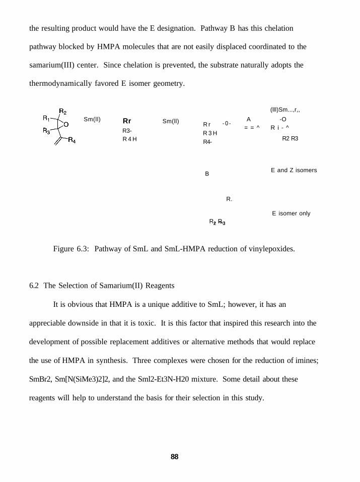
the resulting product would have the E designation. Pathway B has this chelation
pathway blocked by HMPA molecules that are not easily displaced coordinated to the
samarium(III) center. Since chelation is prevented, the substrate naturally adopts the
thermodynamically favored E isomer geometry.
Sm(ll) Rr R3-R 4 H
Sm(ll) R r R 3 H R4-
B
- 0 -
(lll)Sm...,r,,
A -O = = ^ R i - ^
R2 R3
E and Z isomers
R.
R, R 2 "^3
E isomer only
Figure 6.3: Pathway of SmL and SmL-HMPA reduction of vinylepoxides.
6.2 The Selection of Samarium(II) Reagents
It is obvious that HMPA is a unique additive to SmL; however, it has an
appreciable downside in that it is toxic. It is this factor that inspired this research into the
development of possible replacement additives or alternative methods that would replace
the use of HMPA in synthesis. Three complexes were chosen for the reduction of imines;
SmBr2, Sm[N(SiMe3)2]2, and the Sml2-Et3N-H20 mixture. Some detail about these
reagents will help to understand the basis for their selection in this study.
88
SmBr2 was shown to be particularly effective at reducing ketones by Namy and
Kagan. In the case of dodecanal, 2-octanone, cyclohexanone, benzaldehyde, and
acetophenone (examples of both aliphatic acyclic, aliphatic cyclic, and aromatic), high
yields of pinacol were obtained with SmBr2. With the more sterically hindered ketones,
camphor and benzophenone, high yields of reduced alcohol were obtained."' Howers
clearly showed that the samarium Barbier reaction failed to produce the expected
coupling product with SmBr2, instead producing the pinacol exclusively. It was also
noted that SmCL predominantiy forms the pinacol, but to a lesser degree than SmBr2
(approx 3:1 pinacohBarbier product).^" These initial works gave reason to believe that
the bimolecular coupling of imines (analogous to the pinacol) should be readily mediated
by SmBr2.
Sm[N(SiMe3)2]2 was crystallized by Evans, who showed that the complex adopts
a pseudo-tetrahedral geometry in the solid state.^^ This complex has been found to have
appreciable solubility in non-polar solvents (pentane, toluene). This is noticeably
different than SmL, which is only soluble in polar solvents (THF, acetonitrile). Recent
work by Keogh showed that this complex was able to mediate the reduction of nitro
groups to amines.*^ The fact that the complex could be dissolved in toluene allows for
some comparison of solvent effects to similar reactions by SmL. SmL reductions of nitro
groups are only possible in polar solvents.** Another important difference between SmL
and Sm[N(SiMe3)2]2 is that the latter complex has NMR active nuclei. This allowed for
NMR characterization of some of the reaction intermediates from their proposed
mechanism (Figure 6.4). It was concluded that the complete reduction of the nitro group
89

to an amine required six equivalents of Sm[N(SiMe3)2]2. It was also concluded that
Sm[N(SiMe3)2]2 should be less reactive than SmL because of the steric bulk of the bis-
trimethylsilylamide ligands restricting access to the metal center.
2 Sm(NR2)2(thf)2 R = SiMea
2 Sm(NR2)2(thf):
H,0
/ ^ R 2 N ^ N R 2 I Sm
Sm RgN NRj
Sm(NR2)3
2 Sm(NR2)2(thf)2
2 Sm(NR2)2(thf)2
Figure 6.4: Mechanism for reduction of nitro group by Sm[N(SiMe3)2]2-
This last statement was shown to be incorrect by Flowers. Flowers measured rate
constants for the reduction of alkyl iodides (1 -iodobutane) and ketones (2-butanone) by
SmL, SmL-HMPA, and Sm[N(SiMe3)2]2- It was shown that the rate of reduction of alkyl
iodides by Sm[N(SiMe3)2]2 was approximately an order of magnitude faster than SmL-
HMPA (which itself is 10"* faster than SmL) while the rate of ketone reduction was
approximately 10 faster than SmL-HMPA. More to the point, the activation barriers
90

(Ea), and enthalpy of activation (AH'') were found to be significantly lower for
Sm[N(SiMe3)2]2 than for SmL-HMPA. The entropy of activation (AS^) was large for
both reductants (Table 6.2). This lead to the conclusion that the reduction process when
ufilizing Sm[N(SiMe3)2]2 was of considerably more inner-sphere character than that of
SmL-HMPA. To reconcile the disparity between this conclusion and that of Keogh
(that access to the metal center should be limited), it was postulated that while the bis-
trimethylsilylamide ligands are tightiy bound (compared to the iodides of SmL) the two
coordinated THF molecules have increased lability. Thus, displacement of THF by
substrate becomes easier and allows for more inner-sphere character in the electron
transfer step.
Table 6.2: Rate constants and activation parameters for alkyl iodide and ketone reduction by SmL, SmL-HMPA, and Sm[N(SiMe3)2]2.
System( 1-iodobutane) k. M ' sec ' E,, kcal mol' AS'*', cal mol 'K ' AH'*'kcal mol' AG'*', kcal mol" Smiz (8+2) xlO-* Sm(HMPA)6l2 2.6 ±0.1 9.3 ±0.2 -28 ± 1 87 ±0.2 17.3 ±0.3 Sm{N(SiMe3)2}2 19 ± 1 2.3 ±0.1 -47 ± 1 1.7 ±0.1 16,5 ±0,3
Svstem(2-butanone) k. M 'sec ' E,. kcal mol' AS'*', cal mol'K ' AH'*' kcal mol'' AG'*', kcal mol Sml2 (7±3)xl0"^ Sm(HMPA)6l2 ( 8 ± l ) x l O - ' 7.3 ±0.3 -44 ± 1 67 ±0.3 20.3 ±0.4 Sm(N(SiMe3)2}2 (1.7 ±0.3) x 10 2.0±0.3 -43 ± 1 1.4±0.3 14,8±0,6
Hilmersson recently reported the Sml2-Et3N-H20 mixture as an effective reducing
agent. Early work with this mixture showed that dialkyl ketones were reduced 10 faster
than SmL alone. This was also a rate enhancement of 10 over SmL-HMPA (with
alcohol proton source). In this work, they propose that the dramatic increase in rate is
91

caused by a precipitation of Sm(in) after the initial electron transfer. Since it is believed
that the equilibrium between ketone and ketyl radical lies toward the initial ketone, a
precipitation of Sm(III) would force this equilibrium to shift to the right (Figure 6.5). A
balanced equation was given that showed the involvement of three water molecules per
SmL molecule (Equation 6.1). This allows for the formation of Sm(0H)3 and Et3NHI as
by-products. As these salts are not particularly soluble in THF, their precipitation may be
driving the reaction to the right through Le Chatelier's principle.^^
Sml2 Q.
-i-Sm(lll)
O R i ^ - " R 2
Ri R2 Sml2-Et3N-H20 O-^ J^ + Sm(lll)-ppt
^ Ri • R2 Figure 6.5: Equilibrium alteration through precipitation of Sm(ni).
R2C=0 -I- 2SmL + 6H2O -I- 4R3N ==> R2CHOH + 2Sm(OH)3 -1- 4R3N HI (6.1)
This initial work was later expanded upon through an investigation of the
mixture's reactivity toward a,P-unsaturated esters, alkenes, and alkynes. In the case of
a,P-unsaturated esters, the mixture reduced the alkene portion of the molecule selectively,
and was observed to have reaction times of less than ten seconds. In a similar fashion,
alkenes or alkynes could be reduced to alkanes near quantitatively within minutes.
Unfortunately, these reactions only occurred when then there was a conjugated system.
Single double bonds (as in cyclohexene) or non-conjugated double bonds (as in 1,4-
cyclohexadiene) were left untouched by this reagent mixture. Also, in substrates that
92

were not symmetrical (in other words, when reduction of either of two double bonds did
not yield the same product), mixtures resulting from reduction of either double bond were
observed (Figure 6.6). ' '*
(20%) / ^ ^ ^ / ' ^ v . , ^ ^ (12%)
Sml2-Et3N-H20
(12%) (56%)
Figure 6.6: Products of unsymmetrical conjugated double bond reduction by SmL-Et3N-H20.
6.3 Reduction of Imines by Samarium(II) Reagents
Based upon the initial work on these three reagents, we expected them to have the
ability to perform reduction on our imine substrates. As was clearly shown in this work,
this hypothesis is correct, though the findings from the reduction of imines by these three
complexes are somewhat difficult to explain in a logical manner. In other words, if one
asks 'what is the best reagent for imine reduction?', there is no immediate answer. What
needs to be specified are the following aspects of the system in question.
1. Is reducfion (amine formafion) or reducfive coupling desired?
In the case of ketimine substrates, the answer to this is simpler than for aldimines.
Both aromatic and aliphatic ketimines are cleanly reduced to amines by either
Sm[N(SiMe3)2]2 or SmBr2. The SmL-Et3N-H20 mixture promotes bimolecular coupling
for aromatic ketimines, but not aliphatic ones. This means that in the event that the
93

substrate is an aliphatic ketimine, there is no recourse but to not utilize one of these
samarium(II) reagents if coupling is desired. If reduction is the preferred outcome, either
Sm[N(SiMe3)2]2 or SmBr2 should be the preferred reagent. If coupling is desired, only
the Sml2-Et3N-H20 mixture can be utilized. This reagent operates at a much faster rate
than either of the other samarium(n) reagents. Because of this, it generates a higher
concentration of radicals faster, leading to an increased likelihood of two radicals
encountering each other in solution for the bond formation process. Stereoselectivity
with Sml2-Et3N-H20 is typically poor, but careful choice of substrates with substantial
steric bulk, or rigid ring systems can provide coupling products of high stereoselectivity
(see Table 4.6). The reason behind the fact that aliphatic ketimines do not couple is that
after reduction, they give an unstabilized iminyl radical, which likely quickly abstracts a
hydrogen atom from THF. Aromatic ketimines are stabilized by the aromatic system, so
this hydrogen abstraction process is not as rapid.
Aldimines are a much more complicated situation. All three reagents can couple
the simplest substrates, which are unsubstituted, aromatic aldimines. However, only the
Sm[N(SiMe3)2]2 complex gives any significant stereochemical preference, which is for
the anti isomer. Unfortunately, this means that there is no preferred reagent (in term of
yield) if the syn product is desired, and the selection of reagent should be based on other
mitigating factors (reaction time, ease of purification, etc.). Subsfituted aromatic
aldimines are only effectively reduced by the Sml2-Et3N-H20 mixture if the substitution
is at the para position of the ring. In fact, this mixture appears to be the only reagent that
provides a pathway to either the coupled or reduced products. We believe that this is
94

reflective of a mechanistic pathway that involves electron transfer through the benzylic
ring as opposed to direct transfer into the imine bond (Figure 6.7). When the substitution
is at the meta position this result changes. In this case, SmBr2 is clearly superior at
providing the reducfion product, Sm[N(SiMe3)2]2 is the best at providing the anti isomer
of the coupled product, and the Sml2-Et3N-H20 mixture provides the highest yield (albeit
slightly) of coupled product, but is a near equal mixture of syn and anti isomers. Some of
these results are certainly related to the effect of the meta group attached to the benzylic
ring. While it may seem reasonable to assume that a substituent at that position would
not have a significant steric interference, modeling of the iminyl radicals of both the
unsubstituted and subsfituted imine (Figure 6.8) gives evidence that this is not the case.
It seems that placing a group at the meta posifion causes a distinct change in the
orientation of the attached rings. In the substituted case, these rings shield the radical
which has the effect of decreasing the rate of radical-radical coupling.
Sm(l') „ R
]^^„ ^ ,_™IL H ^ x4i#H — X-^-H
Figure 6.7: Pathway for reduction through benzylic position of imines.
95

Figure 6.8: Models of (left) unsubstituted iminyl radical (right) substitued iminyl radical from Spartan modelling.
2. What other factors should be considered?
One concern is always going to be the amount of time elapsed over the course of a
reaction. While none of these reagents require excessively long amounts of reaction
time, the Sml2-Et3N-H20 mixture is by far the fastest. Reaction times with this reagent
are typically completed within five to ten minutes and were not observed to be longer
than one hour (para substituted imines). This reagent was clearly the superior reagent in
this regard, however, neither SmBr2 nor Sm[N(SiMe3)2]2 required longer than 24 hour
periods for reactions they are able to mediate.
The other factor to be considered is that of product purification. Where the SmL-
Et3N-H20 mixture excels at reducing the amount of time required, it has the unfortunate
consequence of producing fair amounts of both reduced and coupled products in all of
96
these reactions. This necessitates a purification step not required by the other two
reagents, which typically only produce one of the two possible reduction products.
6.4 Imine Reduction with Applied Ultrasound
The application of ultrasound to SmL as another alternative to HMPA shows
some promise in our initial studies. This technique seems to readily couple unsubstituted
aldimines or aromatic ketimines effectively, and also couples even para substituted
aromatic aldimines (though a significant amount of reduced amine is observed in some
cases). This reduction appears to be specific to the imine structure (at 20kHz), and
should be noted as an effective method of selecfively reducing this group in the presence
of other reducible funcfional groups, particularly chlorides and ketones. While this
frequency dependence may be unusual, this is not unheard of in sonochemistry. As
menfioned previously, reports by Koda and Kruss individually showed a strong
dependence of certain reactions to the applied frequency. Further studies utilizing
variable frequency ultrasound should be pursued in order to determine what frequencies
provide optimal rates for imine reductions. Unfortunately, there is no established
reference for coupling of frequency to vibrational modes. This may mean that changing
the applied frequency will not allow for other functional groups to be reduced in similar
fashion. Nonetheless, the ability to mediate a reaction selecfively in the presence of other
functional groups is a valuable addition to SmL mediated chemistry.
97
6.5 Photochemical Activation of SmL
The initial work of Ogawa showed that photochemical activation of SmL
increases the reducing power to a significant degree.^^ Our work has expanded on this
observation and shown that this method allows for electron transfer from SmL to imines,
alkyl chlorides, nitriles, alkyl ketones, and conjugated alkenes. A point that should be
elaborated upon is the comparison of actual experimental rate constants to theoretical rate
constants derived from Marcus theory. Marcus theory relates the overall free energy
change of an electron transfer process to the rate by which the electron transfer occurs.
In this model, the reductant (in these experiments, SmL) and the oxidant (the quencher
molecules) are regarded as two spheres. After the excitation of the reductant, the two
species diffuse in solution with a rate determined by the viscosity of the solvent medium.
When reductant and oxidant molecules collide through this diffusion controlled process,
an electron transfer can occur. This is representative of an outer sphere electron transfer.
A mathematical expression for determining the rate of electron transfer through this
mechanism was given by the Marcus equation. The particular form of the Marcus
equation utilized in this work is shown as Equation 5.7 (see Chapter 5, p. 76), where k^ is
the rate of electron transfer, kd is the diffusion controlled rate constant, 1.4 x 10 M" sec"
for THF solvent, 1 is the reorganization energy, and AG° is the free energy of the
reaction.
Marcus theory has some obvious assumptions that can cause deviations from
experimental results. One of these is that in the calculation of AG°, it is assumed that the
active species are hard spheres. In the calculation of AG° throughout this work, we have
98

taken the diameter of the quencher (needed to determine the radius) to be the most
spatially distant atoms after modeling of the substrate, however, many of these substrates
are clearly not spherical in nature. Despite this, and other assumptions in the Marcus
equation, this is a well-established method for the theoretical determination of rate
constants for outer sphere electron transfer processes. What our experiments clearly have
shown is that for photochemical electron transfer processes, experimental rate constants
and the rate constants generated from the Marcus equation are in very good agreement,
with less than a magnitude of order difference between the two values for any given
substrate. It is a commonly held belief that any values within two orders of magnitude of
each other indicate that the process is indeed an outer sphere electron transfer process.
Another important concept involved in these calculations is that of the
reorganization energy, X. This term arises from the change in energy due to the
vibrational and solvation changes due to the electron transfer. This term is typically
considered to be the average of the reorganization energy of both the reductant and
oxidant. However, for the body of this work, we have assumed that the reorganization
energy can be estimated for our systems as the value for a known system, which is the
reduction of an alkyl iodide by SmL. The reorganization energy is comprised as the
average of the reorganization energy of the oxidant and reductant. Both oxidant and
reductant energies have a contribution from an inner sphere and outer sphere component.
The inner sphere portion can be thought of as the individual bond breaking/formation in
the molecule, and the outer sphere portion is then the solvent reorganization after electron
transfer. The overall reorganization energy is therefore comprised of four parts, reductant
99

inner and outer sphere reorganization, and oxidant inner and outer sphere reorganizations.
The model system accurately describes the two reductant portions (as all are SmL in
THF). The oxidant in the model resembles that of our quencher molecules in that all are
reacting from neutral species to form radical species. The reorganization energy from the
outer sphere solvent changes should be comparable, leaving only the energy from the
bond breaking inner sphere portion different. It is believed that this energy is minimal
compared to the solvent reorganization energies, and therefore has been uncorrected for
from the model values.
What we ultimately obtain from the photochemical quenching studies is that this
method provides a pathway to novel SmL mediated reactions, previously unattainable
without the introduction of cosolvents or ligand changes. Comparison of the rates of
reaction with that of ground state SmL, for example in the case of dialkylketones, shows
that the rate of reduction is accelerated by over ten orders of magnitude. This important
discovery is presented as a welcome alternative to the use of HMPA as an accelerant for
SmL mediated reactions.
Analysis of the quenching rate constants provides a general trend in rate of
electron transfer. This trend is aromatic imine > conjugated alkene > nitrile > alkyl
chloride > alkyl ketone. This mimics the same trend as the reduction potentials for the
substrates (see Table 5.2). The agreement between Marcus theory and experimental
values indicate that the electron transfer is an outer-sphere process. The value of this
work can be manifested in the variety of new carbon-carbon bond formation reactions
that can be potentially mediated by photoactivated SmL. For instance, any of these
100

functional groups can be utilized in radical cyclizations to unactivated olefins (Figure 6.9,
note that probable coordinafing Sm(ni) cations not shown for clarity). This provides a
pathway to the synthesis of multicyclic systems from olefin pendant groups.
Figure 6.9: Possible coupling reactions based on photoexcited SmL.
6.6 Samarium(II) Spectroscopy
The remainder of the photochemical experiments provide us with some useful
information as well, beyond that of simple characterization and determination of
fundamental constants. We have clearly recognized that the emission from samarium(II)
species is in actuality, phosphorescence and not fluorescence as it is commonly referred
to in the literature. These experiments show some of the areas of photochemical
samarium chemistry that can be pursued in future work. For example, the determination
of molar extinction coefficients provides these fundamental, and heretofore, unreported
values for these reagents. Beyond that though, it shows us that the actual absorption
process is only of moderate efficiency. These extinction coefficients (for SmL in THF)
range from approximately 580 to 1300 L mole'cm"' (depending on the absorption
maximum of interest), which are reasonable for a Laporte allowed process. These values
101

directly relate that for photochemical electron transfer chemistry, there would be an
advantage to excitation at the higher energy wavelengths. This advantage is that the
complex is more efficient at absorbing those wavelengths of light. The downside to this
is possible bond hemolysis at particularly high wavelengths may occur. Since emission
was only found to occur from one wavelength (760 nm) and was independent of
excitafion wavelength (so long as the excitation overlaps any region of positive
absorbance in the UV-Vis spectrum, which is almost the entirety of 300-700 nm) one can
assume that the photochemical ET will be unaltered by this change in excitation
wavelength. Of course, this assumes that the substrate (quencher) does not absorb these
higher energy wavelengths.
Another factor to be considered in future work is that of the quantum yield.
Utilizing Cu(DMP)2' (in CH2CI2) as a reference, the quantum yields of SmL and SmBr2
were found to be 0.13 and 0.011, respectively. From the synthetic chemist's point of
view, the order of magnitude difference in quantum yield is a reason why SmL should be
preferred over the other samarium(II) reagents in synthetic use. The reason for the
reduction in quantum yield between the iodide and bromide species, and that the value is
lower than unity for both complexes is probably reflective of the excitation energy being
transferred to the bulk solvent as heat. The SmBr2 complex has less steric bulk from the
halide ligands and is more accessible to solvent molecules. Since the exchange occurs
through collisions between the excited species and bulk solvent, there may be some
benefits in cooling the SmL solutions to slow this loss of excitation energy.
102

It may seem that photochemistry of divalent samarium complexes is limited to
SmL, but this is not entirely true. While the Sm[N(SiMe3)2]2 is of littie value in this field
due to its lack of luminescence in THF, SmBr2 does show a muted (compared to SmL),
but discemable emission at 760 nm. Because of this, similar quenching experiments
could be performed with this complex, given a suitable substrate. Though some of the
quencher molecules utilized for experiments with SmL are either reduced by ground state
SmBr2 (notable imine and chlorides), such structures as non-aromatic alkenes or alkynes
may prove suitable for those experiments. SmL-HMPA is known to also phosphoresce,
the problem being that HMPA acts as a stafic quencher upon the activated SmL.
Experiments with this complex would therefore have to utilize minimal amounts of
HMPA in order to have observable emission. Similar to SmBr2, the choice of substrate is
also limited due to the enhanced reactivity of this complex.
6.7 Conclusions
This work clearly shows the importance of ligand selection of divalent samarium
complexes. In the case of imine reductions, change of ligand from the iodide of SmL to a
more strongly coordinative ligand is necessary for mediation of the reaction. The
question that has been answered herein is what that new ligand should be. The steric
bulk of the (-N(SiMe3)2) ligand acts to provide some stereocontrol over coupling
products, with preferences of approximately 3:1 for the anti isomer. The Sml2-Et3N-H20
mixture provides the best opportunity for reductive coupling to occur due to the rapid
reduction of substrates driven by precipitation of by-product salts. None of the reagents
103
studied showed any aptitude for reductive coupling of aliphatic imines, but produce
amines in near quantitative yields instead.
Bimolecular quenching rate constants were found for the photoactivated SmL
species. Rates were found to be in the 10^-10^ range (M"'sec"'), which is considerably
faster than ground state SmL. The calculated rates from Marcus theory were found to be
in good agreement with experimental values, indicating that the electron transfer is
through an outer-sphere process. This method of photoactivating SmL provides an
avenue to a variety of new reactions such as nitrile-olefin or aromatic alkene-olefin
couplings.
The spectroscopy of several samarium(II) reagents was investigated by UV-Vis
and phosphorescence spectroscopy. Molar extinction coefficients for SmL, SmL-HMPA,
SmBr2, and Sm[N(SiMe3)2]2 were calculated in THF solvent. Relative quantum yields
for SmL and SmBr2 were determined to be 0.13 and 0.011, respectively. It was
discovered that the process of emission was actually a phosphorescence rather than
fluorescence as previously thought. These experiments clearly show that SmL is superior
to any of the other samarium(II) complexes in terms of efficiency of photon absorption
(molar extinction coefficient) and emission (quantum yield) and should be utilized
primarily for any photoactivated samarium(II) chemistry.
104

REFERENCES
(1) Kagan, H.B; Sasaki, M.; Collin, J. Pure & Appl.Chem. 1988, 60, 1725.
(2) For example, cerium and samarium comprise 60 mg kg"' and 6.0 mg kg"' of the . earth's crust, which is well above that of tin (2.0 mg kg"') and molybdenum (1.5
mg kg" ). Yet the lanthanide metals are far more expensive to purchase. Cerium and samarium both cost in excess of $50 for 10 gram quantities, whereas tin and molybdenum can be purchased in 100 gram amounts for under $30. (a) Lide, D.R. Handbook of Chemistry and Physics-1991; CRC Press, 1990, p 14-7. (b) Aldrich Chemical Company-Catalog (US), 1999.
(3) Cotton, F.A.; Wilkinson, G.; Murillo, C.A.; Bochmann, M. Advanced Inorganic Chemistry; 6"" edition; New York: John Wiley & Sons, 1999.
(4) Girard, P.; Namy, J.L.; Kagan, H.B. J. Am. Chem. Soc. 1980, 702, 2693.
(5) Luche, J-L. 7. Am. Chem. Soc. 1978,100, 2226.
(6) Imamoto T.; Kusumoto T.; Hatanaka Y.; Yokoyama M. Tetrahedon Lett. 1982, 25(13), 1353.
(7) White, J.D.; Larson, G.L. J. Org. Chem. 1978, 43, 4555.
(8) Hou, Z.; Takamine, K.; Aoki, O.; Shiraishi, H.; Fujiwara, Y.; Taniguchi, H. J. Org. Chem. 1988, 53, 6077.
(9) Aggarwal, V.K.; Mereu, A.; Tarver, G.J.; McCague, R. J. Org. Chem. 1998, 65,7183.
(10) Yu, L.; Chen, D.; Li, L; Wang, P.G. J. Org. Chem. 1997, 62, 3575.
(11) Powell, D.H.; Dhubhghaill, O.M.; Pubanz, D.; Helm, L.; Lebedev, Y.S.; Schlaepfer, W.; Merbach, A.E. J. Am. Chem. Soc. 1996,118, 9333.
(12) Evans, P.A.; Nelson, J.D.; J. Org. Chem. 1996, 61, 7600.
(13) Paolobelli, A.B.; Ceccherelli, P.; Pizzo, F. J. Org. Chem. 1995, 60, 4954.
(14) Fisher, T.H.; Dershem, S.M. J. Org. Chem. 1988, 53, 1504.
(15) Zhang, Y.; Raines, A.J.; Flowers, R.A. Org. Lett. 2003, 5. 2363.
105
(16) Zhang, Y.; Flowers, R.A. J. Org. Chem. 2003, 68, 4560.
(17) Annunziata, R.; Benaglia, M.; Cinquini, M.; Raimondi, L. Eur. J. Org. Chem. 1999, 3369.
(18) Kunishima, M.; Hioki, K.; Kono, K.; Sakuma, T.; Tani, S. Chem. Pharm. Bull. 1994,^2,2190.
(19) Molander, G.A.; McKie, J.A. J. Org. Chem. 1992, 57, 3132.
(20) Molander, G.A.; Sono, M. Tetrahedron 1998, 54, 9289.
(21) Lebrun, A.; Namy, J-L.; Kagan, H.B. Tetrahedron Lett. 1993, 34, 2311.
(22) Knettle, B.W.; Flowers, R.A. Org. Lett. 2001, 3, 2321.
(23) Taniguchi, Y.; Nagata, K.; Kitamura, T.; Fujiwara, Y. Tetrahedron Lett. 1996, 37, 3465.
(24) Sigalov, A.B.; Rybakova, L.F.; Beletskaya, I.P. B. Acad. Sci. USSR. Chem. Sci. 1983, 1094.
(25) Gracia, I.S.; Dietrich, H.; Bobo, S.; Chiara, J.L. J. Org. Chem. 1998, 63, 5883.
(26) Hamann, B.; Namy, J-L.; Kagan, H.B. Tetrahedron 1996, 52, 14225.
(27) Shabangi, M.; Sealy, J.M.; Fuchs, J.R.; Flowers, R.A. Tetrahedron Lett. 1998, 39, 4429.
(28) Hasegawa, E.; Curran, D.P. J. Org. Chem. 1993, 53, 5008.
(29) Inanaga, L; Ishikawa, M.; Yamaguchi, M. Chem. Lett. 1987, 1485.
(30) Miller, R.S.; Sealy, J.M.; Shabangi, M.; Kuhlman, M.L.; Fuchs, J.R.; Flowers, R.A. J. Am. Chem. Soc. 2000, 722, 7718.
(31) Collin, L; Giuseppone, N.; Machrouhi, F.; Namy, J-L.; Nief, F. Tetrahedron Lett. 1999,40,3161.
(32) Evans, W.J.; Drummond, D.K.; Zhang, H.; Atwood, J.L. Inorg. Chem. 1988, 27, 575.
(33) Prasad E.; Knettle B.W.; Flowers R.A. J. Am. Chem. Soc. 2002,124, 14663.
106

(34) Machrouhi, F.; Namy, J.-L. Tetrahedron Lett. 1999, 40, 1315.
(35) Imamoto, T.; Nishimura, S. Chem. Lett. 1990, 1141.
(36) Basu, M.K.; Becker, F.F.; Banik, B.K. Tetrahedron Lett. 2000, 41, 5603.
(37) Ogawa, A.; Sumino, Y.; Nanke, T.; Ohya, S.; Sonada, N.; Hirao, T., J. Am. Chem. Soc. 1997,779,2745.
(38) Molander, G.A.; Alonso-Alija, C; J. Org. Chem. 1998, 63, 4366.
(39) Molander, G.A. J. Org. Chem. 1999, 64, 4119.
(40) Molander, G.A.; Kollner, C. J. Org. Chem. 2000, 65, 8333.
(41) Kende, A.S.; Curran, D.P. J. Am. Chem. Soc. 1979, 707, 1857.
(42) Scott, W.L.; O'Donnell, M.J.; Delgado, F.; Alsina, J. J. Org. Chem. 2002, 67, 2960.
(43) March, L; Advanced Organic Chemistry: Reactions, Mechanisms, and Structure; 4"" edition. New York: John Wiley & Sons, 1992.
(44) Mohar, B.; Valleix, A.; Desmurs, J-R.; Felemez, M.; Wagner, A.; Mioskowski, C. Chem. Commun. 2001, 2572.
(45) Lucet, D.; Le Gall, T.; Mioskowski, C. Angew Chem. Int. Ed. 1998, 37, 2580.
(46) Weingarten, H.; Chupp, LP.; White, W.A. J. Org. Chem. 1967, 32, 3246.
(47) Procedure for this method: A mixture of ketone and amine (1.2 equiv.) were refluxed in either pentane or benzene solvent. The water by product is removed as the bottom portion in the Dean-Stark trap over 24 hours. After cooling, the remaining solution is purified by removal of the solvent by rotary evaporation, followed by disfillation of the crude product.
(48) Mignani, S.; Mouysset, D.; Le Roy, I.; Stella, L. Synthetic Commun. 2000, 30, 3685.
(49) Selwood, P.W. J. Am. Chem. Soc. 1934, 56, 2392.
(50) Fuchs, J.R.; Mitchell, M.; Shabangi, M.; Flowers, R.A., II Tetrahedron Lett. 1997, 5S, 8157.
107

(51) Lebrun, A.; Rantze, E.; Namy, J-L.; Kagan, K.B. New J. Chem. 1995,19, 699.
(52) Dahlen, A.; Hilmersson, G. Tetrahedron Lett. 2002, 43, 7197.
(53) Dahlen, A.; Hilmersson, G. Tetrahedron Lett. 2003, 44, 2661.
(54) Dahlen, A.; Hilmersson, G. Chem. Eur. J. 2003, 9, 1123.
(55) Dahlen, A.; Hilmersson, G.; Knettie, B.W.; Flowers, R.A. J. Org. Chem. 2003, 68, 4870.
(56) Imamoto, T.; Nishimura, S.; Chem. Lett. 1990, 7. 1141.
(57) Shiue, J.S.; Lin, M.H.; Fang, J.M. J. Org. Chem. 1997, 62, 4643.
(58) Thompson, L.H.; Doraiswamy, L.K. Ind. Eng. Chem. Res. 1999, 38, 1215.
(59) Bremner, D.H. Ultrason. Sonochem. 1994, 7, SI 19.
(60) Javed, T.; Mason, T.J.; Phull, S.S.; Baker, N.R.; Robertson, A. Ultrason. Sonochem. 1995, 2, S3.
(61) Kojima, Y.; Koda, S.; Nomura, H. Ultrason. Sonochem. 2001, 8, 75.
(62) Kruus, P.; Burk, R.C,; Entezari, M.H.; Otson, R. Ultrason. Sonochem. 1997, 4, 229.
(63) Rawn, J.D. Biochemistry New York: Harper & Row, 1983.
(64) Leigh, W.J.; Postigo J.A. Can. J. Chem. 1995, 73, 191.
(65) Das, A.; Joshi, V.; Kotkar, D.; Pathak, V.S.; Swayambunathan, V.; Kamat, P V.; Ghosh, P.K. J. Phys. Chem. 2001, 705, 6945.
(66) Skoog, D.A., Principles of Instrumental Analysis, 3''' Ed. Saunders College Publishing, 1985, 231.
(67) Lakowicz, J.R. Principles of Fluorescence Spectroscopy, 2" Ed. New York: Kluwer Academic/Plenum Publishers, 1999, 239-246.
(68) Houle, M.P.; Agent, T.S.; Kiefer, G.E.; McMillan, K.; Bomhop, D.J. Appl. Spectrosc. 1996,50, 1221.
108
(69) Sharipov, G.L.; Ostakhov, S.S.; Ableeva, N. S.; Voloshin, A.L; Kazakov, V.P.; Tolstikov, G.A. Russ. Chem. Bull. 1993, 42, 1749.
(70) van der Tol, E.B.; van Ramesdonk, H.J.; Verhoeven, J.W.; Steemers, F.J.; Kerver, E.G.; Verboom, W.; Reinhoudt, D.N. Chem. Eur. J. 1998, 4, 2315.
(71) Dorenbos, P. J. Phys.Condens. Mat. 2003, 75, 575.
(72) Payne, S.A.; Chase, L.L.; Kxupke, W.F. J. Chem. Phys. 1988, 88, 6751.
(73) McMillin, D.R.; Buckner, M.T.; Ahn, B.T. Inorg. Chem. 1977, 76, 943.
(74) Demas, J.N.; Crosby, G.A.; J. Phys. Chem. 1971, 75, 991.
(75) Skene, W.G.; Scaiano, S.C; Cozens, F.L. J. Org. Chem. 1996, 67, 7918.
(76) Bard, A.L; Lund, H. Encyclopedia of Electrochemistry of the Elements, Vol XIV, New York: Marcel Dekker, Inc. (US) 1980.
(77) Bard, A.L; Lund, H. Encyclopedia of Electrochemistry of the Elements, Vol XII, New York: Marcel Dekker, Inc. (US) 1978.
(78) Prasad, E.; Knettle, B.W.; Flowers, R.A. unpublished results.
(79) Bard, A.L; Lund, H. Encyclopedia of Electrochemistry of the Elements, Vol XV, New York: Marcel Dekker, Inc. (US) 1984.
(80) Prasad, E.; Knettle, B.W.; Flowers, R.A. unpublished results.
(81) Fox, M.A.; Chanon, M. Photoinduced Electron Transfer, Part C. New York: Elsevier, 1988.
(82) Eberson, L. Electron Transfer Reactions in Organic Chemistry, New York: Springer Verlag, 1987.
(83) Shabangi, M.; Kuhlman, M.L.; Flowers, R.A. Org. Lett. 1999, 7, 2133.
(84) Shotwell, J.B.; Sealy, J.M.; Flowers, R.A. J. Org. Chem. 1999, 64, 5251.
(85) Hou, Z.; Zhang, Y.; Wakatsuki, Y. Bull. Chem. Soc. Jpn. 1997, 70, 149.
(86) Aurrecoechea, J.M.; Iztueta, E. Tetrahedron Lett. 1995, 36, 7129.
109
(87) Brady, E.B.; Clark, D.L.; Keogh, D.W.; Scott, B.L.; Watkin, J.G. J. Am. Chem. Soc. 2002, 124,1001.
(88) Banik, B.K.; Mukhopadhyay, C; Venkatraman, M.S.; Becker, F.F. Tetrahedron Lett. 1998, 39, 7243.
110

APPENDK A
DETERMINATION OF TERM SYMBOLS
Term symbols are a method for representing the valence state of an atom.
Typically these are utilized in metal-based complexes. Their primary use is that they
allow for a simple representation of the electrons in the atom, allowing for such things as
electronic transitions to be described without the use of complicated schematics or
equations. Unfortunately, the term symbols themselves can be confusing to the novice
chemist. This appendix provides a brief explanation for the determination of term
symbols and references for more detailed explanations of this concept.
The typical term symbol consists of three parts and is arranged in the following
generic fashion: ^b- The three parts are (a) the spin multiplicity of the atom in question,
(T) the orbital angular momentum, and (b) the total angular momentum quantum number.
A suggestion for calculating the term symbol would be to start by finding the
orbital angular momentum first (T). While not a necessity, this may make calculation of
the other parameters simpler. This requires some knowledge of the valence state of the
atom in question. One can dismiss any closed shell or sub-shell, and focus on only partial
filled sub-shells. For example, if one examines the carbon atom, one finds that the
electronic configuration is ls^2s^2p^. For term symbol calculation, we focus on the
partially filled 2p sub-shell.
I l l

Once you know the identity of the valence sub-shell and the number of electrons
located within, draw a picture representing the number of orbitals contained in that sub-
shell. For carbon, this is three orbitals (of equivalent energy. Figure A-1).
Figure A-1: 2p orbital representation.
Now number the orbitals as on a graph, starting with zero in the middle orbital,
and progressing in a positive direction to the left, and negative values to the right (Figure
A-2). Note that all orbital sub-shells have an odd number of orbitals (s=l, p=3, d=5, f=7)
so the numerical pattem will always be symmetrical upon completion.
1 0 -1
Figure A-2: 2p orbitals after numerical assignment.
Now place one electron in each orbital, following Pauli's principle so that all
orbitals are half filled before spin pairing in any orbital occurs, until all the valence
electrons are accounted for (Figure A-3). Note that the orbitals should be filled in order
from most positively assigned to most negafive.
1 0 -1
Figure A-3: 2p orbitals after carbon valence electrons are accommodated.
112
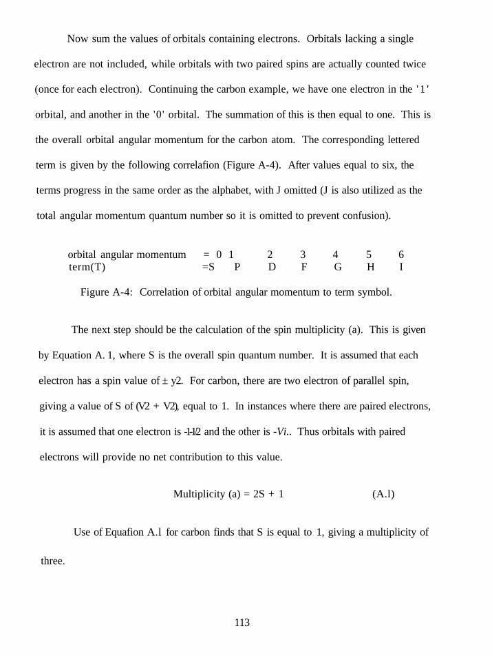
Now sum the values of orbitals containing electrons. Orbitals lacking a single
electron are not included, while orbitals with two paired spins are actually counted twice
(once for each electron). Continuing the carbon example, we have one electron in the ' 1 '
orbital, and another in the '0' orbital. The summation of this is then equal to one. This is
the overall orbital angular momentum for the carbon atom. The corresponding lettered
term is given by the following correlafion (Figure A-4). After values equal to six, the
terms progress in the same order as the alphabet, with J omitted (J is also utilized as the
total angular momentum quantum number so it is omitted to prevent confusion).
orbital angular momentum = 0 1 2 3 4 5 6 term(T) =S P D F G H I
Figure A-4: Correlation of orbital angular momentum to term symbol.
The next step should be the calculation of the spin multiplicity (a). This is given
by Equation A. 1, where S is the overall spin quantum number. It is assumed that each
electron has a spin value of ± y2. For carbon, there are two electron of parallel spin,
giving a value of S of (V2 + V2), equal to 1. In instances where there are paired electrons,
it is assumed that one electron is -1-1/2 and the other is -Vi.. Thus orbitals with paired
electrons will provide no net contribution to this value.
Multiplicity (a) = 2S + 1 (A.l)
Use of Equafion A.l for carbon finds that S is equal to 1, giving a multiplicity of
three.
113

The final term to calculate is that of the total angular momentum quantum number
(b). This is given by Equafion A.2, where L is simply the overall orbital angular
momentum (T) and S is the overall spin quantum number calculated above.
b = IL-l-SI, IL-1-S-ll....lL-SI (A.2)
In general, the ground state will minimize this term, so (b) is usually equal to the
last term, IL-SI. In the case of carbon, one obtains the following sequence (Figure A-5).
IL-l-SI IL-l-S-ll IL-SI 2 1 0
Figure A-5: Calculated total angular momentum quantum numbers for carbon.
This completes all the necessary calculations. Assembling the calculated values
gives a term symbol for (ground state) carbon of PQ.
In some cases, the calculation of (b) is omitted or not stated in the term symbol.
Without delving into the depths of theory, this omission is explained in the following
manner. The total angular momentum quantum number represents the various energy
sub-levels of the term energy. Typically, these sub-levels are very close in energy (for
any particular value of the orbital angular momentum) and relate little information. This
is a common practice as this value can be calculated with ease from the remaining parts
of the term symbol (L and S are both included in the remainder of the term symbol,
simple algebra allows their determination).
114
The same steps are followed for more complicated systems (more electrons, more
orbitals, etc.). An example of this might be the samarium system described in the main
body of this manuscript. Again, begin by determining the electronic configuration of the
atom in question so that you may calculate the orbital angular momentum (T). For
samarium(II), the ground state electronic configurafion is (written according to Aufbau
principle) ls^2s^2p^3s^3p^4s^3d'°4p^5s^4d'°5p^4f^ (samarium metal contains 6s^ electrons
which are lost when oxidized to the (II) state). This means that the sub-shell of interest is
the 4f level. Proceed to draw the 4f orbitals as seven equivalent orbitals (Figure A-6).
Figure A-6: 4f orbital representation.
Number the orbitals of as graph, starting with zero in the central orbital, again
proceeding in a positive direction to the left (Figure A-7).
3 2 1 0 - 1 - 2 - 3 Figure A-7: 4f orbitals after numerical assignment.
Now place the six available electrons in the orbitals, adhering to Pauli's principle
and filling the most positively numbered orbitals first (Figure A-8).
3 2 1 0 - 1 - 2 - 3 Figure A-8: 4f orbitals after addition of valence electrons.
115
Proceed to sum the values of electron containing orbitals. In this case you should
obtain a value of (3-«-2-t-l-i-0-f(-l)-i-(-2)) which equals three. Referring to Figure A-4
obtains the term to be an 'F' state.
Next, calculate (a), the spin multiplicity. Since there are six electrons of parallel
spin, and each electron counts as Vi, the overall spin quantum number, S, is equal to
(6 X V2), which is three. Using this value in Equation A.l provide a mulfiplicity value of
seven.
Lastly, calculate the total angular momentum quantum number (b) using Equation
A.2 and the values of L (3) and S (3).
b = IL-HSI IL-i-S-ll IL-J-S-21 IL-HS-31 IL-hS-41 IL-HS-51 IL-SI 6 5 4 3 2 1 0
The minimal value for (b) is found to be zero. Assembling these values then
provides a term symbol for ground state samarium(II) as FQ.
116

APPENDIX B
SPECTRA AND SPECTRAL DATA
»'
; ? ; . .
-! \
*
t
• rsss 1 ? " - ; S - £
' j u . ' • • ' ^ " *
* * ^ " '™: : : : : : ; ; : r : : : : : " . — ^ - ' • " ' ^b ^
f ....."
Figure B-1: 'H NMR of products from reduction of the N-butyl imine of benzaldehyde.
B-1 (syn) 5 0.73-0.76 (t, 6H), 1.03-1.12 (m, 4H), 1.21-1.43 (m, 4H), 2.20-2.30 (m, 4H), 3.72 (s, 2H), 7.00-7.32 (m, lOH).
B-1 (anti); 6 0.83-0.86 (t, 6H), 1.21-1.43 (m, 8H), 2.35-2.43 (m, 4H), 3.60 (s, 2H), 7.00-7.32 (m, lOH).
B-1 (reduced) 50.89-0.92 (t, 3H), 1.21-1.51 (m,4H), 2.62-2.65 (t, 2H), 3.79 (s, 2H), 7.00-7.32 (m, 5H).
117
'
• i
,
, • £ | ti\ •^•\
a.
iii SB' z '
» i
i': . i i • ^
-)•' EI | __
J
miHiMi i i i i
, 1 1 ^ ^ ^ ' ' " " ' • • • " " '
•
. iSGS^t'w'iSr'
J B B W W w u a u W ' " " " " '
f""-
^ r V
/• ^ ynr^=-=-~-
1
u...
' • • ' • • . ' • .
* **'
; /
1 «•-{
Vn 2
'"f". iJ-^ "• i ;
jr
"4 •* T * * 3 > * . : : ;
' ~*\« ^
H ?
Figure B-2: H NMR of products from reduction of the N-benzyl imine of benzaldehyde.
B-2 (syn) 6 3.45 (center of AB system, 4H), 3.79 (s, 2H), 7.0-7.5 (m, 20H).
B-2 (anti) 5 3.61 (center of AB system, 4H), 3.74 (s, 2H), 7.0-7.5 (m, 20H).
B-2 (reduced) 6 3.84 (4H, s), 7.0-7.5 (lOH, m).
118

Figure B-3: H NMR of products from reduction of the N-benzyl imine of p-methyl
benzaldehyde.
B-3 (syn) 6 2.31 (s, 6H), 3.46 (center of AB system, 4H), 3.74 (s, 2H), 7.0-7.5 (m, 18H).
B-3 (anti) 5 2.41 (s, 6H), 3.60 (center of AB system, 4H), 3.73 (s, 2H), 7.0-7.5 (m, 18H).
B-3 (reduced) 6 2.38 (s, 3H), 3.81 (s, 2H), 3.84 (s, 2H), 7.0-7.5 (m, 9H).
19

- •
,:,
sV
'
'
pr S'
"'
i i~-
a
1
'''r^:„7,,
1
**"" 1
^ . . . „ -_^_ • ' " •
, •s:
-L-'sriii "
m f
^
4. h
*> *
J
Figure B-4: 'H NMR of products from reduction of the N-benzyl imine of/j-methoxy benzaldehyde.
B-4 (syn) 5 3.43 (center of AB system, 4H), 3.67 (s, 2H), 3.89 (s, 6H), 6.78-7.78 (m, 18H).
B-4 (anti) 5 3.58 (center of AB system, 4H), 3.65 (s, 2H), 3.84 (s, 6H), 6.78-7.78 (m, 18H).
B-4 (reduced) 6 3.76 (s, 2H), 3.81 (s, 2H), 3.85 (s, 3H), 7.0-7.5 (m, 9H).
120

j
. '
'\
f-' -
t i
1
i
• . . . - • « W9k~«
1 s
1
^.^..^...^.j;;^ — ,.i«,™.
1
,
>-->
1 ^•"
!
» »<
.J..^
X., [§2
,-..•.': ?4i'
* • * .'--
• ^ ^
Figure B-5: H NMR of products from reduction of the N-benzyl imine of p-
trifluoromethyl benzaldehyde.
B-5 (syn) 5 3.47 (center of AB system, 4H), 3.87 (s, 2H), 7.0-7.6 (m, 18H).
B-5 (anti) 5 3.57 (center of AB system, 4H), 3.88 (s, 2H), 7.0-7.6 (m, 18H).
B-5 (reduced) 5 3.77 (s, 2H), 3.80 (s, 2H), 7.0-7.5 (m, 9H).
121

Figure B-6: H NMR of products from reduction of the N-benzyl imine of /n-methyl benzaldehyde.
B-6 (syn) 6 2.40 (s, 6H), 3.45 (center of AB system, 4H), 3.82 (s, 2H), 6.93-7.40 (m, 18H).
B-6 (anti) 5 2.29 (s, 3H), 2.40 (s, 3H), 3.62 (center of AB system, 4H), 3.82 (s, 2H), 6.93-7.39 (m, 18H).
B-6 (reduced) 6 2.39 (s, 3H), 3.82 (s, 2H) 3.85 (s, 2H), 6.93-7.40 (m, 9H).
m

Figure B-7: H NMR of products from reduction of the N-benzyl imine of acetophenone.
B-7 (syn) 5 1.54 (s, 6H), 3.44 (center of AB system, 4H), 7.0-7.35 (m, 20H).
B-7 (anti) 5 1.65 (s, 6H), 3.44 (center of AB system, 4H), 7.0-7.35 (m, 20H).
B-7 (reduced) 1.39 (d, 3H), 3.64 (center of AB system, 2H), 3.83 (q, IH), 7.2-7.4 (m, lOH).
123

*
. " • .
tfSi:;3irar;4i! SE
•i 5
- !=:•- K'
-'—— ~~
," "IT.: IH: t I « f ••".
•ii! YV=- iWl-i^-V'i
I I
•• • • r o
Figure B-8: 'H NMR of products from reduction of the N-benzyl imine of 3-methyl-2-butanone.
B-8 (reduced) 5 0.87-0.91 (m, 6H), 0.99-1.01 (d, 3H), 1.67-1.78 (m, IH), 2.48-2.55 (m, IH), 3.69-3.75 (d, IH), 3.80-3.87 (d, IH), 7.2-7.37 (m, 5H).
124
" V '•
• '• ' 'fl' ' Hi:
• 555: : j : - ' = : - -> i
-=l; ini isiisi'if;
'•'>/
Figure B-9: 'H NMR of products from reduction of the N-benzyl imine of pinacolone.
B-9 (reduced) 5 0.88 (s, 9H), 0.96-1.04 (d, 3H), 2.25-2.33 (m, IH), 3.62-3.69 (d, IH), 3.89-3.96 (d, IH), 7.19-7.38 (m, 5H).
125

""
"•.i<
-
' :
'HiT-f * ^
— "-- ','' '• i .
8
''•'•ii'-}''-'-^' " * s
5 iM.^.^
. _ ,. „
_ ;-; .
.—"^^^msm-™- - - •'•'"
, -, .
'" is"
k •55!
;
'^v"""ijli 11;;! i i . .tiH • H I S - :
-1-. JHI^S ' : 1.: « l : j " •* ;
.1 I., J i.. .•s-'*''','-,'v -i:r 1=1 :-4,-s; .' 'y7«
f . i t
\ ';'
1
» I T
11 =-p ry^-•^v ' - . •''
-O
°0 -->. V
Figure B-10: 'H NMR of products from reduction of the 2-phenyl-l-pyrroline.
B-10 (anti) 5 1.25-1.38 (m, IH), 1.39-1.50 (m, IH), 1.63-1.78 (m, 2H), 1.88-2.00 (m, IH), 2.05-2.23 (m, 2H), 2.24-2.36 (m, IH), 2.36-2.64 (br. s, 2H), 2.64-2.79 (m, 2H), 2.92-3.07 (m, 2H), 6.99-7.22 (m, lOH).
126
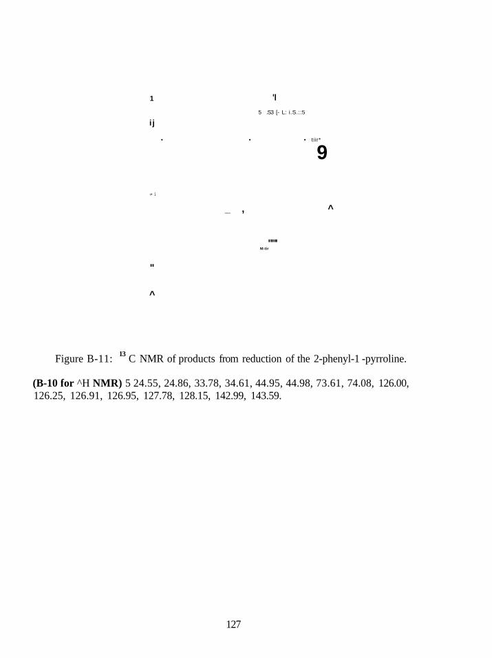
1
i j
«• 1
"
^
'I
5 .S3 [- L: i.S.::5
• • • ti ir*
9
_ , ^
""' M-tir
13 Figure B-11: C NMR of products from reduction of the 2-phenyl-1 -pyrroline.
(B-10 for ^H NMR) 5 24.55, 24.86, 33.78, 34.61, 44.95, 44.98, 73.61, 74.08, 126.00, 126.25, 126.91, 126.95, 127.78, 128.15, 142.99, 143.59.
127

Figure B-12: H NMR of N-butyl imine of benzaldehyde.
B-12: 50.95-0.98 (t, 3H), 1.40-1.42 (m, 2H), 1.69-1.71 (m, 2H), 3.62-3.63 (t, 2H), 7.40-7.41 (m, 3H), 7.72-7.73 (m, 2H), 8.27 (s, IH).
128

Figure B-13: H NMR of N-benzyl imine of benzaldehyde.
B-13: 5 4.86 (s, 2H), 7.22-7.45 (m, 8H), 7.81-7.83 (m, 2H), 8.39-8.46 (s, IH).
129

*
I .
='• „
-,
'\
'. i ' ' i
• i '•
.-;_z-_:r--v;
.„.
• " " " • • - " 1 ^ -
1 \^^\
^
• ' • ' "
•••• i .
'$}
Figure B-14: 'H NMR of N-benzyl imine of p-methyl benzaldehyde.
B-14: 5 2.39 (s, 3H), 4.82 (s, 2H), 7.22-7.35 (m, 7H), 7.68-7.69 (d, 2H), 8.37 (s, IH).
130
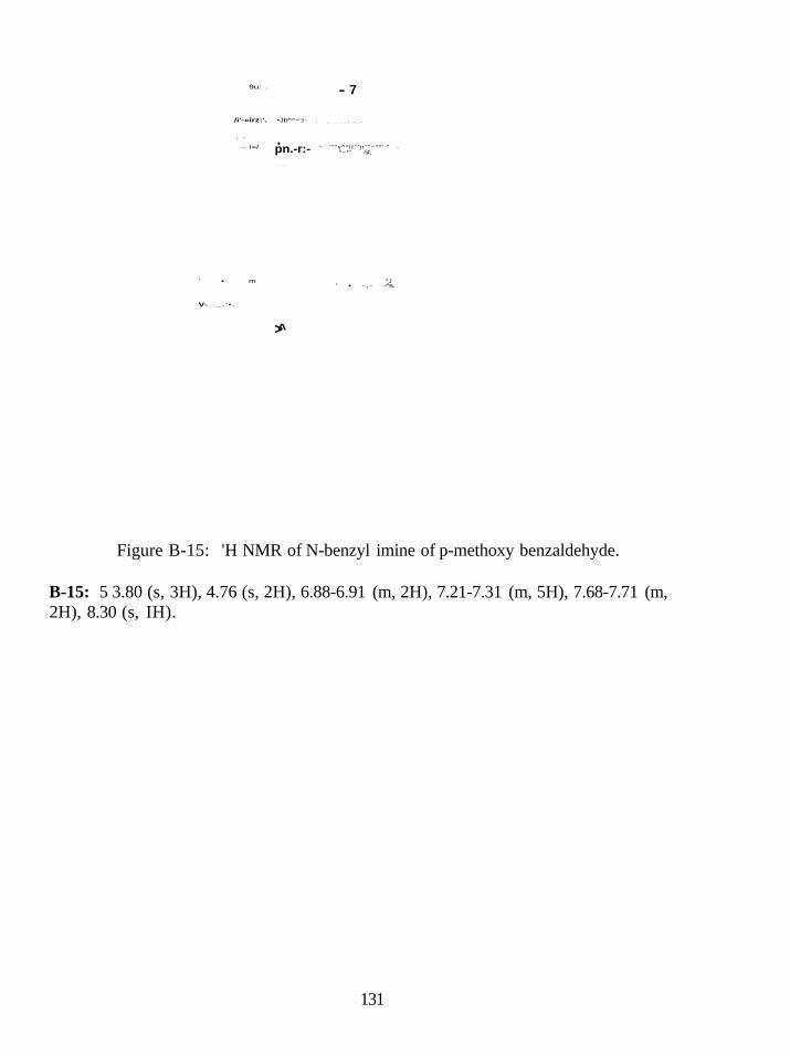
9u: .
/i'-»irz:'.
• ^
- i»/
' • m
V- _ . ' • .
•Jb^^~:r- .
. pn.-r:-
- • * . . .
>
- 7
• . - - . - . ^ - ^ • ^
~ ' " " v ^ ^ l r " ' j r " " ~ * * ' " -^~*" -5f,
^J ' • - , - - s.
Figure B-15: 'H NMR of N-benzyl imine of p-methoxy benzaldehyde.
B-15: 5 3.80 (s, 3H), 4.76 (s, 2H), 6.88-6.91 (m, 2H), 7.21-7.31 (m, 5H), 7.68-7.71 (m, 2H), 8.30 (s, IH).
131

Figure B-16: H NMR of N-benzyl imine of p-trifluoromethyl benzaldehyde.
B-16: 6 4.86 (s, 2H), 7.26-7.36 (m, 5H), 7.66-7.68 (d, 2H), 7.88-7.89 (d, 2H), 8.44 (s, IH).
132

. i . i • '•—
'il i ' !si ; ^raaaK-a~7-
\ i ) i
J
i f \
? ,. 1 '. „ .„„
' •
fi ••
f !
-i
J 8 :
i.tji
-. ' " • !
••--:'•'.:.! :k;: '••"•"•""•
i illr 1 ?""j
?
!;!*« " " " • . , • — ^ " »
- "I
^^ i?r f /^-. >.*
' ' I
Figure B-17: 'H NMR of N-benzyl imine of m-methyl benzaldehyde.
B-17: 5 2.41 (s, 3H), 4.84 (s, 2H), 7.26-7.67 (m, 9H), 8.40 (s, IH).
133

Figure B-18: 'H NMR of N-benzyl imine of acetophenone.
B-18: 5 2.35 (s, 3H), 4.76 (s, 2H), 7.24-7.44 (m, 8H), 7.87-7.89 (m, 2H).
134

N
L Figure B-19: 'H NMR of N-benzyl imine of 3-methyl-2-butanone.
B-19: 5 1.13-1.15 (d, 6H), 1.86 (s, 3H), 2.51-2.65 (m, IH), 4.50 (s, 2H), 7.18-7.38 (m, 5H).
135

-i '
V - = ^
" i \
• • • ,
i \ '•
% .
X s
, 5 c F . S -
' \
1 ^ . t •-) Mi
• - • - : - r
Figure B-20: H NMR of N-benzyl imine of pinacolone.
B-20: 5 1.18 (s, 9H), 1.88 (s, 3H), 4.52 (s, 2H), 7.10-7.38 (m, 5H).
136