Reaction null-space control of flexible structure mounted ...yoshida/paperlist/IEEE TRA15-6...
13
IEEE TRANSACTIONS ON ROBOTICS AND AUTOMATION, VOL. 15, NO. 6, DECEMBER 1999 1011 Reaction Null-Space Control of Flexible Structure Mounted Manipulator Systems Dragomir N. Nenchev, Member, IEEE, Kazuya Yoshida, Member, IEEE, Prasert Vichitkulsawat, and Masaru Uchiyama, Member, IEEE Abstract—A composite control law for end-effector path track- ing with a flexible structure mounted manipulator system is proposed, such that no disturbances on the flexible base are in- duced. The control law is based on the reaction null space concept introduced earlier to tackle dynamic interaction problems of free- floating robots, or moving base robots in general. The control law is called composite since it ensures base vibration suppression control as well, although independently of the reactionless motion control subtask. The requirement of task independence is essen- tial to avoid the appearance of complex dynamics expressions in the control law, such as nonlinear velocity-dependent coupling terms and dependencies of inertias on the elastic coordinates. We present experimental data from computer simulations and the experimental test bed TREP developed at Tohoku university. The experimental data is shown to agree well with theory. Index Terms—Flexible structure mounted manipulator system, reaction null space control, vibration suppression control. I. INTRODUCTION T HE concept of a so-called macro-micro manipulator system was introduced by Sharon and Hardt [1]. A small, high-bandwidth manipulator was mounted on the end of a larger one, and the former was controlled to compensate inac- curacy due to the latter. This concept has evolved throughout the years to meet mainly two types of application demands: nuclear waste cleanup [2], [3] and space robotics [4], [5]. We shall refer to such manipulator systems as flexible structure mounted manipulator systems, or FSMS in short. The control of an FSMS is quite challenging due to complex dynamics, and the presence of dynamic coupling between the two substructures in particular. Such coupling exists regardless of whether the macro part is set in motion or kept stationary. The former case is clearly the more difficult one [6]–[8]. In the latter case, the macro subsystem can be modeled as a passive flexible structure. The motivation behind this case is that, usually, the large arm is actively controlled only when relocating the small arm. Once located at the work site, the small arm is controlled to perform a dextrous operation. Manuscript received April 27, 1998; revised February 2, 1999. This paper was recommended for publication by Associate Editor W. Wilson and Editor S. Salcudean upon evaluation of the reviewers’ comments. This work was supported by the Ippan C Research Project 07805027 Grand-in-Aid for Scientific Research, Ministry of Education, Science, and Culture, Japan. D. N. Nenchev is with the Department of Intelligent Machines and System Engineering, Hirosaki University, Hirosaki 036-8561, Japan. K. Yoshida and M. Uchiyama are with the Department of Aeronautics and Space Engineering, Graduate School of Engineering, Tohoku University, Sendai 980-8579, Japan. P. Vichitkulsawat is with T. Napa A. Muang, Chonburi 20000, Thailand. Publisher Item Identifier S 1042-296X(99)10415-4. Thereby, it may induce some undesirable disturbance in the large passive arm [9]. This latter case will be discussed herein. Literature survey shows that for single-arm FSMS three main control subtasks can be identified: (1) base vibration suppression control [9]–[12], (2) design of control inputs that induce minimum vibrations 1 [13], and (3) end-point control in the presence of vibrations [14], [15]. A major conclusion is that till now, control subtasks have been tackled mostly separately. Only recently attempts are being made to combine control subtasks into one controller with improved performance. One example is the work of Cannon et al. [13], where control subtasks (1) and (2) were combined. Another example is the work of Hanson and Tolson [16]. The authors discuss the important problem of end-point control in combination with vibration suppression control. It should be noted that this task can be solved only when redundancy is present. Hanson and Tolson introduce therefore a kinematically redundant micro part. Vibration suppression control is derived from the null space of the manipulator Jacobian. The main aim of this work is to propose a composite control law capable of solving all of the three control subtasks above. This composite control makes use of an approxi- mated inverse dynamics model. The approximation reduces computational cost and real-time control becomes feasible despite the complex nature of the problem. Note that real- time is an important issue because the main control mode of FSMS is teleoperation. In spite of the approximation, our approach remains general enough to cover not only single- arm FSMS but also FSMS’s with multiple dextrous arms. Such systems we consider important because they enable a control strategy which can be based on so-called dynamic redundancy. As already explained, by necessity, we have to consider the presence of redundancy. Kinematic redundancy is one candidate, however, it might not always be a good solution to the problem at hand. Note that kinematic redundancy resolution techniques suffer from the presence of algorithmic singularities. The work of Hanson and Tolson demonstrates this fact. On the other hand, dynamic redundancy is ensured by incorporating actively controlled dynamic parameters, such as inertias and link centroid locations [7]. Such type of control can be obtained via proper arm motion control of FSMS’s with multiple dextrous arms [5]. The main contribution of the present work is the com- bination of two methods developed earlier for free-flying 1 We will refer to this subtask also as “reactionless (end-effector) path tracking.” 1042–296X/99$10.00 1999 IEEE
Transcript of Reaction null-space control of flexible structure mounted ...yoshida/paperlist/IEEE TRA15-6...
IEEE TRANSACTIONS ON ROBOTICS AND AUTOMATION, VOL. 15, NO. 6, DECEMBER 1999 1011
Reaction Null-Space Control of FlexibleStructure Mounted Manipulator Systems
Dragomir N. Nenchev,Member, IEEE,Kazuya Yoshida,Member, IEEE,Prasert Vichitkulsawat, and Masaru Uchiyama,Member, IEEE
Abstract—A composite control law for end-effector path track-ing with a flexible structure mounted manipulator system isproposed, such that no disturbances on the flexible base are in-duced. The control law is based on the reaction null space conceptintroduced earlier to tackle dynamic interaction problems of free-floating robots, or moving base robots in general. The control lawis called composite since it ensures base vibration suppressioncontrol as well, although independently of the reactionless motioncontrol subtask. The requirement of task independence is essen-tial to avoid the appearance of complex dynamics expressions inthe control law, such as nonlinear velocity-dependent couplingterms and dependencies of inertias on the elastic coordinates.
We present experimental data from computer simulations andthe experimental test bed TREP developed at Tohoku university.The experimental data is shown to agree well with theory.
Index Terms—Flexible structure mounted manipulator system,reaction null space control, vibration suppression control.
I. INTRODUCTION
T HE concept of a so-calledmacro-micro manipulatorsystemwas introduced by Sharon and Hardt [1]. A small,
high-bandwidth manipulator was mounted on the end of alarger one, and the former was controlled to compensate inac-curacy due to the latter. This concept has evolved throughoutthe years to meet mainly two types of application demands:nuclear waste cleanup [2], [3] and space robotics [4], [5]. Weshall refer to such manipulator systems asflexible structuremounted manipulator systems, or FSMS in short.
The control of an FSMS is quite challenging due to complexdynamics, and the presence of dynamic coupling between thetwo substructures in particular. Such coupling exists regardlessof whether the macro part is set in motion or kept stationary.The former case is clearly the more difficult one [6]–[8]. Inthe latter case, the macro subsystem can be modeled as apassive flexible structure. The motivation behind this caseis that, usually, the large arm is actively controlled onlywhen relocating the small arm. Once located at the work site,the small arm is controlled to perform a dextrous operation.
Manuscript received April 27, 1998; revised February 2, 1999. This paperwas recommended for publication by Associate Editor W. Wilson and EditorS. Salcudean upon evaluation of the reviewers’ comments. This work wassupported by the Ippan C Research Project 07805027 Grand-in-Aid forScientific Research, Ministry of Education, Science, and Culture, Japan.
D. N. Nenchev is with the Department of Intelligent Machines and SystemEngineering, Hirosaki University, Hirosaki 036-8561, Japan.
K. Yoshida and M. Uchiyama are with the Department of Aeronauticsand Space Engineering, Graduate School of Engineering, Tohoku University,Sendai 980-8579, Japan.
P. Vichitkulsawat is with T. Napa A. Muang, Chonburi 20000, Thailand.Publisher Item Identifier S 1042-296X(99)10415-4.
Thereby, it may induce some undesirable disturbance in thelarge passive arm [9]. This latter case will be discussed herein.
Literature survey shows that for single-arm FSMS threemain control subtasks can be identified: (1) base vibrationsuppression control [9]–[12], (2) design of control inputs thatinduce minimum vibrations1 [13], and (3) end-point control inthe presence of vibrations [14], [15]. A major conclusion is thattill now, control subtasks have been tackled mostly separately.Only recently attempts are being made to combine controlsubtasks into one controller with improved performance. Oneexample is the work of Cannonet al. [13], where controlsubtasks (1) and (2) were combined. Another example is thework of Hanson and Tolson [16]. The authors discuss theimportant problem of end-point control in combination withvibration suppression control. It should be noted that this taskcan be solved only when redundancy is present. Hanson andTolson introduce therefore a kinematically redundant micropart. Vibration suppression control is derived from the nullspace of the manipulator Jacobian.
The main aim of this work is to propose a compositecontrol law capable of solving all of the three control subtasksabove. This composite control makes use of an approxi-mated inverse dynamics model. The approximation reducescomputational cost and real-time control becomes feasibledespite the complex nature of the problem. Note that real-time is an important issue because the main control modeof FSMS is teleoperation. In spite of the approximation, ourapproach remains general enough to cover not only single-arm FSMS but also FSMS’s with multiple dextrous arms.Such systems we consider important because they enable acontrol strategy which can be based on so-calleddynamicredundancy.As already explained, by necessity, we have toconsider the presence of redundancy. Kinematic redundancy isone candidate, however, it might not always be a good solutionto the problem at hand. Note that kinematic redundancyresolution techniques suffer from the presence of algorithmicsingularities. The work of Hanson and Tolson demonstratesthis fact. On the other hand, dynamic redundancy is ensuredby incorporating actively controlled dynamic parameters, suchas inertias and link centroid locations [7]. Such type of controlcan be obtained via proper arm motion control of FSMS’s withmultiple dextrous arms [5].
The main contribution of the present work is the com-bination of two methods developed earlier for free-flying
1We will refer to this subtask also as “reactionless (end-effector) pathtracking.”
1042–296X/99$10.00 1999 IEEE
1012 IEEE TRANSACTIONS ON ROBOTICS AND AUTOMATION, VOL. 15, NO. 6, DECEMBER 1999
space robot control and for flexible-link manipulator control.First, we will show that the technique for reactionless motionplanning [18], [19] and control [20] of a free-flying spacerobot, referred to as thereaction null spaceapproach, is wellsuited to the problem at hand. Via the reaction null spaceapproach we provide a solution to the second control subtaskidentified above. Thereafter, within the same framework, weintroduce a vibration suppression control law (control subtaskone) similar to that used for vibration suppression in flexible-link manipulators [21]. Finally, we show how to extend theformulation to cover also the third control subtask.
The paper is organized as follows. Section II introducesnotation and gives some background on the vibration sup-pression control approach for flexible link manipulators ofKonnoet al. [21] and the reaction null space approach [22]. InSection III, we show how the concept of reaction null spacerelates to FSMS. Section IV introduces two control laws forbase vibration suppression. Section V discusses reactionlessend-effector path tracking control. Sections VI and VII presentexperimental data from a computer simulation and from theexperimental setup TREP at Tohoku university, respectively.Finally, the conclusions are given in Section VIII.
II. NOTATION AND BACKGROUND
A. Equation of Motion
We consider a manipulator arm consisting ofjoints. Thesystem dynamicscan be written in the following form, see e.g.[9]:
(1)
where denotes the positional and orientationaldeflection of the base with respect to the inertial frame2,
stands for the joint coordinates of the arm,and denote base inertia, damping and
stiffness, respectively. is the inertiamatrix of the arm. denotes the so-calledinertia coupling matrix. and arevelocity-dependent nonlinear terms, denotes arm jointdamping and is the joint torque. We do not considerexternal forces here, including the gravity force, having inmind a noncontact task in micro gravity environment. Wenote, however, that the micro gravity assumption should notbe regarded as a restriction upon the scope of the methodintroduced herein. Gravity terms can be included into theabove equation of motion. A respective compensating termin the control laws below would then account for the presenceof gravity, without invalidating the results.
We will now briefly overview two existing techniquesto be used as a base in further derivations. One of themis the flexible-link manipulator active vibration suppressiontechnique of Konnoet al. [21]. The other one is based onthe reaction null space approach to a moving base robot [22].
2Fixed at the equilibrium position/orientation. Generally,m = 6 (n � m):
These techniques have been independently developed, eachone using a different assumption to approximate the complexdynamics.
B. The Vibration Suppression Control Subtask
The vibration suppression control subtask has been solvedby Lee and Book [9] based on the singular perturbationtechnique. Another possible approach is that of Konnoetal. used for active vibration suppression of a flexible-linkmanipulator [21]. At this point, we should note that theequation of motion of a flexible-link manipulator has exactlythe same structure as (1) above. The difference is that theflexible coordinates of the FSMS are concentrated at the base,while those of the flexible-link manipulator are distributed overthe kinematic chain [23].
The essential assumptions in the work of Konnoet al aretwo:
1) since the arm is stationary at the initial instant, thenonlinear velocity-dependent terms and are ap-proximated with zero
2) the deflections are assumed small, and hence, all inertiasubmatrices are approximated to be functions of the jointvariables only.
Note that, also in the case of an FSMS, these two assumptionsare sufficient to cancel all velocity-dependent terms, includingthose which do not contain the joint velocity explicitly (i.e.,
Then, the upper part of the equation ofmotion can be linearized around the equilibrium of the base
(2)
Without loss of generality, here and henceforth we mayignore base damping. Choosing the control acceleration as
(3)
where is a constant gain matrix, denotesthe right pseudoinverse of the inertia coupling matrix3, andnoting that being an unit matrix of properdimension, we obtain a damped vibrational system.
C. Reactionless Motion Control Subtask
The assumption regarding a stationary initial state of themanipulator is essential in view of a flexible-link manipulator,where the number of elastic coordinates is usually larger thanthe number of actuators (in our terms, Now, let usconsider the opposite case: a system comprising more actuatorsthan elastic degrees of freedom. In this case we can relax theconstraint for stationary initial configuration. The reason is asfollows.
At we assume a stationary base Then, welook for motions in the micro part which would maintain thezero state of the base. Since the base is stationary, again, allinertia submatrices will be functions of the joint variables only.
3The right pseudoinverse can be used, sincen � m and HHHbm isassumed full rank. Note, for a flexible-link manipulator the number of elasticcoordinates is larger than the number of actuators (in our termsm > n); andhence, the left pseudoinverse has to be employed [21].
NENCHEV et al.: REACTION NULL-SPACE CONTROL 1013
In addition, all nonlinear velocity-dependent terms contributedby the base deflection rate will be zero.
With a stationary base as initial condition, the base reactionwrench due to motion of the arm can be written as
(4)
where denotes the position of the total center of massof the arm, stand for the inertia matrix,angular velocity, mass and center-of-mass position for link
respectively, and The base reaction can berewritten in terms of arm joint variables, as follows:
(5)
The state of stationary base will be maintained under amanipulator control law, if it exists, such that forall In this case, base equilibrium is
(6)
Note the difference when compared with the result from theprevious subsection: the term does not appear in (2)because of the assumption of stationary initial configuration.Our further derivation will be based on the last equation sincethe main assumption here is
The specific motion of the manipulator that maintains baseequilibrium, i.e.
(7)
we call reactionless manipulator motion. The above equationcan be integrated to
(8)
where is the integration constant.This integral has been calledthe coupling momentum[24].
III. T HE REACTION NULL-SPACE OF FLEXIBLE
STRUCTURE MOUNTED MANIPULATOR SYSTEMS
The reaction null space concept has been originally formu-lated with regard to free-floating space robots [18], [19]. Herewe apply the same idea within the framework of FSMS’s.
A. The Inverse Problem
We are interested in specific manipulator motion whichwould induce zero disturbance to the base.
Proposition 1: (Zero reaction)The manipulator does not induce any reactions to the base
if and only if the coupling momentum is conservedconst for all
The proof follows from the direct examination of (5) and(8).
The inverse problem is defined as “given the condition ofreactionless motion, i.e. zero base reaction (or equivalently,constant coupling momentum), find the joint acceleration (orthe joint velocity) which would maintain this condition.”
As already pointed out, the assumption that the systemat hand has more actuators than elastic degrees of freedom
plays an important role herein. This is in facta kinematic redundancy condition, with respect to the basemotion task.
Proposition 2: At a manipulator configuration such thatrank rank
1) Zero reaction is achieved with the joint acceleration
(9)
where is arbitrary;2) The coupling momentum is conserved with the joint
velocity
(10)
where denotes again an arbitrary vector.
Proof: Substituting from (9) into (5) and taking intoaccount that under the above rank conditionone obtains with any initial joint velocityand also Similarly, substituting from(10) into one obtains wherethe initial velocity is such that
The expression appearing inboth (9) and (10), stands for the projector onto the null space( ) of the inertia coupling matrix.
Definition 2: The null space of the inertia coupling matrixis called the reaction null-space of an FSMS.
From (10) it is apparent that the joint velocity comprisestwo components: one from the reaction null space, and theother from its orthogonal complement. The reaction null-spacecomponent does not contribute to the coupling momentum, andhence, it would yield zero reaction.
Corollary: With zero initial coupling momentum, zero re-action is obtained with the velocity
(11)
We are interested in the component especially from thestandpoint of integrability. At each manipulator configuration
the columns of the null space projector inducea smooth distribution [25] in joint space. In case of well-conditioned inertial coupling at (i.e. the rank conditionfor the inertia coupling matrix in Proposition 2 holds),then the distribution is nonsingular. According to Frobenius’theorem, a distribution is completely integrable, if and only if itis involutive. Involutivity can be examined via Lie brackets onthe columns of If such involutivity can be established,then the reaction null space component of the joint velocitywill be integrable.
Definition 3: The integral of (11), if it exists, is calledtheset of reactionless paths of an FSMS.
The reactionless paths guarantee decoupling between thebase dynamics and the manipulator dynamics. Unfortunately,their existence cannot be always guaranteed. The only casewhen integrability is guaranteed, is that of a one-dimensionaldistribution (i.e., Nevertheless, in some importantpractical cases the system can be recast to fit into this category.
1014 IEEE TRANSACTIONS ON ROBOTICS AND AUTOMATION, VOL. 15, NO. 6, DECEMBER 1999
B. Existence of the Reaction Null-Space
A necessary condition for the existence of the reactionnull-space is the availability of any of the following features:
1) kinematic redundancy;2) dynamic redundancy;3) selective reaction null-space;4) rank deficiency of the inertia coupling matrix.
We utilized kinematic redundancywhen deriving the solu-tion in the previous section. Recall the SSRMS/SPDM systemas a representative example of this category [5]. On the otherhand, we applied the concept of dynamic redundancy [17]to the general problem of moving base robotics and reactionmanagement control [22] in assuming that special devices,called reaction compensators, are present. These devices areused just to control the reaction on the base, similarly to theusage of reaction wheels for satellite attitude control.
There are some applications, such as nuclear waste cleanupFSMS, when the stiffness of the flexible base along someof the generalized coordinates can be sufficiently charac-terized as high-stiffness while in other directions it wouldbe characterized as low-stiffness. Reactions along the high-stiffness directions do not disturb the base at all. In thiscase we introduce theselective reaction null space. Denotea selection matrix by diag wherespecifies a Cartesian-space low-stiffness direction, requiringzero base reaction, while otherwise. Then, we denotethe selective reaction null space as Obviously,dim dim Generally, a reaction nullspace of higher dimension is desirable, since it yields moreDOF when planning the reactionless motion.
Finally, the reaction null space will also exist when theinertia coupling matrix is rank deficient. Locations where
is rank deficient constitute submanifolds in joint space.Thus, if one wishes to exploit rank deficiency to obtainreactionless motion, proper analysis should be done. Thisapproach, however, would limit accessible areas in workspace,which is not desirable from a practical viewpoint. In our studybelow, we will therefore consider only the first three cases ofreaction null space existence. On the other hand, we note thatthe inversion algorithms derived in Section III-A ((9) and (10))utilize the pseudoinverse of the inertia coupling matrix. Sincepseudoinversion is sensitive to ill conditioning, care should betaken to avoid neighborhoods of such locations.
Finally, we note that sufficient conditions for the existenceof the reaction null-space are related to the problem of design.Detailed analysis of this problem goes beyond the scope ofthe present work. We note here that increasing the number ofdegree of freedom (DOF) does not necessarily increase thedimension of the reaction null space. Also, note that motionin some of the DOF’s, such as wrist motion for example, mayyield quite insignificant inertial coupling. Taking an articulatedarm with a distinctive upper/lower elbow arm structure as atypical example (e.g., the SSRMS), it should be apparent thatreactionless motion can be obtained within the main arm plane.Reactions due to base rotation (which changes the orientationof the arm plane) are difficult to be compensated under thecondition of kinematic redundancy. If one considers additional
compensators, such as torque control gyros at the base, thenbase rotation disturbance is compensable via the dynamicredundancy condition.
IV. V IBRATION SUPPRESSIONCONTROL OF FSMS
Vibration suppression via inertia coupling is a well-knownapproach applied to FSMS (cf. e.g. [9]), and flexible-linkmanipulators [21]. Note that no redundancy (in terms ofexistence of the (selective) reaction null space) was assumed.As already explained, the presence of such redundancy impliesthe existence of continuous manipulator motion that doesnot disturb the equilibrium of the elastic subsystem—base orflexible link structure. Even in case of nonstationary (vibrating)base, we can expect that reactionless motion will have aminimal (though not exactly zero) contribution to the changeof the state of the base.
We will propose two control laws for vibration suppression.The first one makes use of the assumptions in Section II-Bwhich have been successfully exploited for vibration suppres-sion of flexible-link manipulators [21]. The second control lawwill be based on exact cancellation of the nonlinearities.
A. Acceleration-Based Vibration Suppression Control
Recall that when the base vibrates, (9) does not exactlyreflect the dynamics; there will be additional coupling dueto velocity dependent nonlinear terms and due to base posi-tion/attitude dependent change of the inertias. Nevertheless,the assumptions in Section II-B can be used since the base isregarded as a passive structure, eventually vibrating around itsequilibrium.
Equation (3) can be directly applied to effectively suppressbase vibration when the initial arm configuration is stationary.This control law has to be modified, however, to reflect thepresence of redundancy:
Proposition 3: (Acceleration-based vibration suppressioncontrol)
In the presence of redundancy, the control
(12)
where is an arbitrary control input, ensures optimal (in aleast squares sense) vibration suppression control.
Proof: Substituting the above control law into (6), weobtain
(13)
where use has been made of the identity
(14)
The last equation shows that with proper choice of theconstantgain we obtain a damped vibrational system. Optimal-ity in least squares sense follows from the property of thepseudoinverse.
An important result, following from the above identity, isthat the arbitrary control input has no contribution to thevibration dynamics. Hence, this control is potentially usefulfor other control tasks. We shall come back to the problem inthe following subsection.
NENCHEV et al.: REACTION NULL-SPACE CONTROL 1015
Remark 1: As noted in [21], no torque appears explicitly inthe control equation. Nevertheless, it was shown that imple-mentation of this control law into a velocity-based closed-loopservo controller is straightforward.
Remark 2: It is well known from studies of kinematicallyredundant systems that the pseudoinverse induces a nonin-tegrable distribution. This results in drift in configurationspace. When the FSMS does not dissipate energy, vibrationsuppression would result in nonzero coupling momentumconservation, and hence, constant drift of the manipulator ininertial space. In reality, joint damping always exists (cf. theterm in (1)), and therefore, the arm would stop after awhile. In spite of this, it might be desirable to have controlover the joint damping process. Hence, we modify our controllaw as
(15)
where is the joint damping control gain. This is possible,since vibration suppression control may admit superpositionof a manipulator joint-space nonlinear control law, providedthe gains are selected with special care [9], [21].
B. Torque-Based Vibration Suppression Control
Proposition 4: (Torque-based vibration suppression con-trol)
Consider the control law
(16)
where
Under well-conditioned inertial coupling, the above controlguarantees that system damping is achieved.
Proof: From the system dynamics (1) we eliminate thejoint acceleration by solving first the upper part forand then,substituting the result into the lower part. We obtain
(17)
where
The closed-loop system is given by
(18)
or
(19)
where we assumed that joint damping has been exactly can-celed out with Premultiplying first by andthen by we obtain
(20)
where use has been of the identity (14). Under well-conditioned inertial coupling, the matrix expression
is full rank. Then, with properchoice of the constant gain base vibration will besuppressed.
Remark 1: The above derivation shows that base vibrationcan be suppressed even with
Remark 2: The condition for exact cancellation of jointdamping can be relaxed in order to gain controllability overarm drift (cf. the discussion in the preceding subsection).
V. REACTIONLESS END-EFFECTORMOTION CONTROL
The main difference between existing vibration suppressioncontrols [9], [21] and our control law (12), is the appearanceof the term in the latter, and also in the torque-basedcontrol law (16). Below, we will show that this term is usefulto derive areactionless end-effector motioncontrol law.
First, recall that the set of reactionless motion under thecondition of a stationary base, as given in (9), is parameterizedby the unknown vector To determine this vector we employthe end-effector kinematics
(21)
where denotes task coordinates andis the end-effector Jacobian. We assume that the number oftask coordinates is less then the actuators Notethat the reference frame is at the base. After some formulamanipulation, one obtains
(22)
where is a restricted Jacobian matrix appearingtypically in redundancy resolution schemes [26]. It can beshown that for any and hence, the secondterm on the right hand side is indeed a reaction null spacevector. Thus, we can write
(23)
Consider now the followingProposition 4: (Reactionless end-effector motion control)Let the control law be given by (16) with
(24)
where is the desired end-effector path, isthe path tracking error and and denote proper gainmatrices. With a well-conditioned restricted Jacobiantheend-effector error converges to zero asymptotically.
Proof: Substitute (23) and (24) into the closed-loop (19),under the condition of a stationary base, to get
(25)
Since both and are full rank, with a proper choice ofthe gains and the end-effector path tracking error mustgo to zero, asymptotically.
1016 IEEE TRANSACTIONS ON ROBOTICS AND AUTOMATION, VOL. 15, NO. 6, DECEMBER 1999
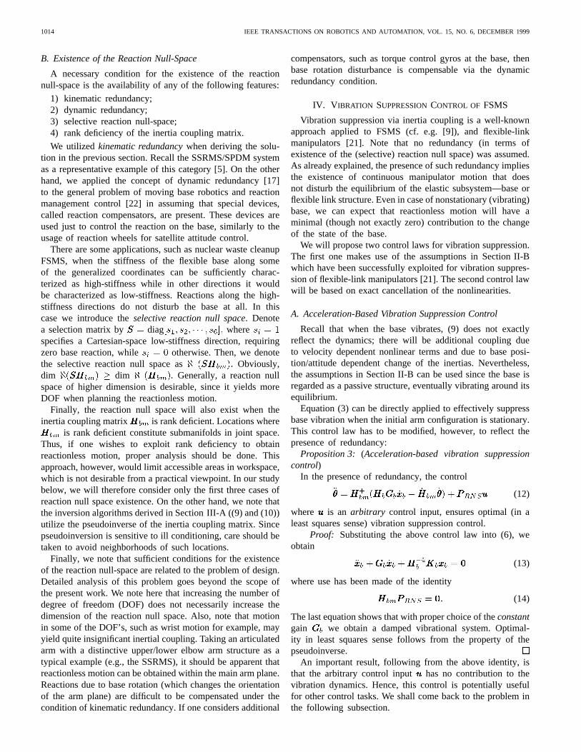
Fig. 1. Acceleration based controller block diagram.
Remark: The full rank condition for the restricted Jacobianimplies
1) well-conditioned inertial coupling (since the inertia cou-pling matrix appears in the formula of this Jacobian);
2) a nonsingular configuration of the manipulator (since themanipulator Jacobian appears in the formula);
3) avoiding any “task conflicts” which are reflected viaso-called “algorithmic singularities,” well-known fromstudies on kinematically redundant manipulators.
In summary, we obtained twocompositecontrol laws, oneacceleration based the other torque based, given by (12) and(16) respectively, in combination with (24). The structure ofthe controllers is essentially the same. Thus, implementationswill depend upon the motor drivers at hand. As will be shownbelow, it is even possible to implement the system withinvelocity based motor drivers, by approximating appropriatelythe acceleration based control law. A block diagram for theacceleration based controller is shown in Fig. 1. It is seen thata resolved acceleration controller (RAC) is embedded into thestructure. Feedback information is required for joint anglesand velocities, and for the flexible base tip deflection (spatial)velocity.
Each of the control laws is capable of, strictly speaking,either base vibration suppressionor reactionless end-effectorpath tracking (i.e., control subtasks one and two, respectively,as identified in the introduction). As far as the third controlsubtask is concerned (end-effector control in the presenceof vibration), the above derivations show that it can besolved via any of the above schemes, provided there is tasksequencing such that end-effector control is initialized onlyafter vibration suppression has been completed. Of course,such task sequencing would introduce additional complexity.Fortunately, the experiments below show that the sequencingcan be avoided in practice, and the two subtask can beinitialized simultaneously.
VI. REACTION NULL SPACE VIA KINEMATIC
REDUNDANCY: SIMULATION STUDY
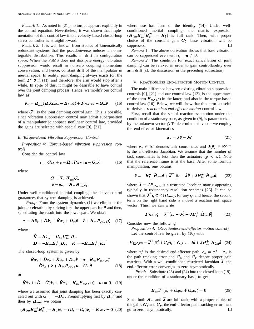
We shall illustrate our approach first with a planar 3Rmanipulator mounted on a horizontally translating base, whichis attached to the inertial frame through a linear spring and adamper. Zero gravity environment is assumed. The parametersof the base are: mass kg, damping Nsmstiffness Nm The parameters of the manipulatorare: link length m, link masskg lumped at the center of each link, link moments of inertiahave been ignored.
Fig. 2. Model of a kinematically redundant FSMS tracking a reactionlesspath.
Fig. 2 shows the system, tracking with its end-point apath without inducing any disturbances to the base. Sincethe reaction null space is 2-D, it is possible to track anypath in task space which complies with well-conditionedinertial coupling and full rankness of matrix Because of thedecoupling property of the reaction null space, the selectionof the feedback gains is not critical: for example, for theend-point control high gains are used diags diag s The gain for base vibrationsuppression control was 10 rad
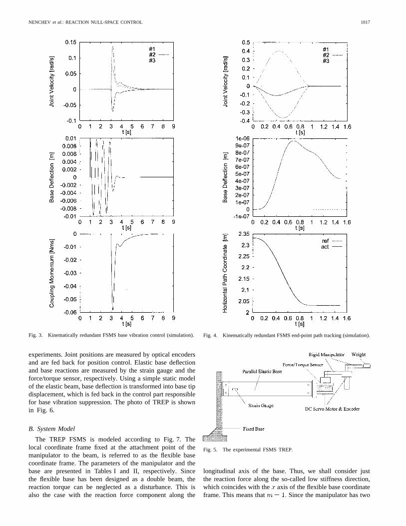
First, base vibration suppression is demonstrated. We as-sume that base vibration is excited due to some external forceat s (see Fig. 3). The base vibrates, with decreasingamplitude because of the natural damping. At sthe vibration control is activated. We have included a jointdamping term diag s into thecontrol law for vibration suppression, which guarantees thatjoint velocity decreases to zero. As already mentioned, ifjoint damping would not be present, the manipulator wouldbe loaded with a nonzero coupling momentum which isconserved, and which would result in constant drift of themanipulator.
Next, end-effector control is demonstrated. There is noinitial deflection of the base. The path is similar to thatdepicted in Fig. 2, and was planned through a fifth orderspline. Other planning can be also used; there is no requirementfor zero boundary conditions. Fig. 4 shows the results. Thereference path4 is tracked perfectly, with practically zero basedisturbance. Note, that the manipulator comes entirely to rest;no external energy has been introduced into the system whichwould have caused arm drift.
VII. T HE SELECTIVE REACTION
NULL SPACE: EXPERIMENTAL STUDY
A. Experimental Setup
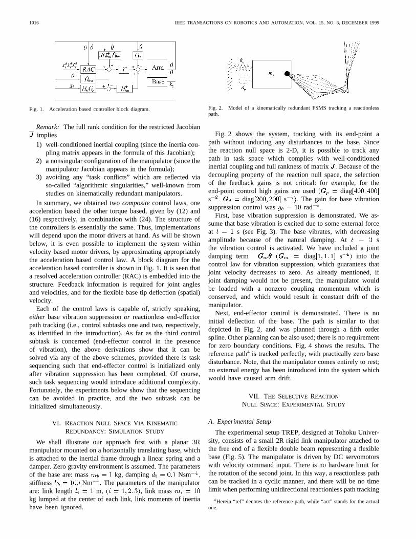
The experimental setup TREP, designed at Tohoku Univer-sity, consists of a small 2R rigid link manipulator attached tothe free end of a flexible double beam representing a flexiblebase (Fig. 5). The manipulator is driven by DC servomotorswith velocity command input. There is no hardware limit forthe rotation of the second joint. In this way, a reactionless pathcan be tracked in a cyclic manner, and there will be no timelimit when performing unidirectional reactionless path tracking
4Herein “ref” denotes the reference path, while “act” stands for the actualone.
NENCHEV et al.: REACTION NULL-SPACE CONTROL 1017
Fig. 3. Kinematically redundant FSMS base vibration control (simulation).
experiments. Joint positions are measured by optical encodersand are fed back for position control. Elastic base deflectionand base reactions are measured by the strain gauge and theforce/torque sensor, respectively. Using a simple static modelof the elastic beam, base deflection is transformed into base tipdisplacement, which is fed back in the control part responsiblefor base vibration suppression. The photo of TREP is shownin Fig. 6.
B. System Model
The TREP FSMS is modeled according to Fig. 7. Thelocal coordinate frame fixed at the attachment point of themanipulator to the beam, is referred to as the flexible basecoordinate frame. The parameters of the manipulator and thebase are presented in Tables I and II, respectively. Sincethe flexible base has been designed as a double beam, thereaction torque can be neglected as a disturbance. This isalso the case with the reaction force component along the
Fig. 4. Kinematically redundant FSMS end-point path tracking (simulation).
Fig. 5. The experimental FSMS TREP.
longitudinal axis of the base. Thus, we shall consider justthe reaction force along the so-called low stiffness direction,which coincides with the axis of the flexible base coordinateframe. This means that Since the manipulator has two

1018 IEEE TRANSACTIONS ON ROBOTICS AND AUTOMATION, VOL. 15, NO. 6, DECEMBER 1999
Fig. 6. A photo of the experimental FSMS TREP.
Fig. 7. The model of TREP.
motors the (selective) reaction null space is one-dimensional, meaning that there is one nonzero vector in thereaction null space. The inertia coupling matrix of this modelcan be determined from the equation for the velocity of the
Fig. 8. Reactionless paths in the workspace of TREP.
Fig. 9. Experimental controller block diagram.
manipulator center of mass, projected onto the low-stiffnessaxis. This is written as
(26)
where denotes the total mass of the manipulator,and stands for the inertia couplingmatrix, with
The reaction null space vector becomes then
(27)
Zero initial coupling momentum will be conserved with anyjoint velocity along the reaction null space vector. This vectorinduces a one-dimensional distribution in joint space, which isalways integrable. Consequently, the set of reactionless pathsof the system can be obtained. This set is displayed in Fig. 8.
C. Control Law Derivation
The derivation of the composite control law follows thatpresented in Section IV. More specifically, we will use theacceleration-based formulation which is most suitable formotor drivers admitting velocity commands, as is the casewith TREP.
Equation (6) assumes the form
(28)
where denotes the deflection of the base from its equilib-rium point. The control law (15) is written as
(29)

NENCHEV et al.: REACTION NULL-SPACE CONTROL 1019
(a) (b)
Fig. 10. Base vibration: (a) with vibration suppression and (b) without vibration suppression (experiment).
where is the additional control input. Because of the orthog-onality between the two terms and it is clear thatthey will not influence each other. The pseudoinverseensures the most efficient (in a least-squares sense) inertialcoupling between the base and the manipulator.
The fact that the reaction null space is one-dimensionalshows that there is only one degree-of-freedom left for theend-point control. This degree-of-freedom is realized as anydesired (scalar) acceleration along the reactionless path. Inpractice this means that even very high velocity/accelerationwould be admissible, as long as the motion does not deviatefrom the current reactionless path.
To adjust the composite control (29) to velocity commandbased motor drivers, we integrate the control. Thereby weassume that the rate of change of is much slower thenthe rate of change of which is justified if one considersthe fact that can be regarded as a “fast” variable. Thus,when integrating the term we assume a constant
and obtain the following approximate integral form ofthe composite control (29):
(30)
where It is apparent that thereference reactionless path (determined by the integral in (30))is tracked under position feedback control, making use of thegain Note that such representation was possible, sincecan be chosen arbitrarily. A block diagram of the controlleris shown in Fig. 9.
D. Experiments
We have conducted a series of experiments for vibrationsuppression, reactionless path tracking and composite control.In all the experiments, the initial configuration was the same:the arm was extended and aligned with the flexible base
1) Vibration Suppression:This experiment was performedat a fixed configuration, coinciding with the initial configura-tion mentioned above. The control law (30) was used, wherethe integral was replaced by the joint angles values of thefixed configuration. A relatively small position control gainwas selected: s The vibration gain was chosen as
s An arbitrary external force input was applied.Fig. 10(a) and (b) show the results for the cases with andwithout vibration suppression, respectively. The effectivenessof the vibration suppression was confirmed.
1020 IEEE TRANSACTIONS ON ROBOTICS AND AUTOMATION, VOL. 15, NO. 6, DECEMBER 1999
(a) (b)
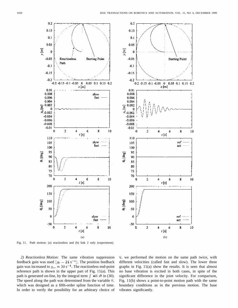
Fig. 11. Path motion: (a) reactionless and (b) link 2 only (experiment).
2) Reactionless Motion:The same vibration suppressionfeedback gain was used s The position feedbackgain was increased to s The reactionless end-pointreference path is shown in the upper part of Fig. 11(a). Thispath is generated on-line, by the integral term in (30).The speed along the path was determined from the variablewhich was designed as a fifth-order spline function of time.In order to verify the possibility for an arbitrary choice of
we performed the motion on the same path twice, withdifferent velocities (called fast and slow). The lower threegraphs in Fig. 11(a) show the results. It is seen that almostno base vibration is excited in both cases, in spite of thesignificant difference in the joint velocity. For comparison,Fig. 11(b) shows a point-to-point motion path with the sameboundary conditions as in the previous motion. The basevibrates significantly.
NENCHEV et al.: REACTION NULL-SPACE CONTROL 1021
(a) (b)
Fig. 12. Reactionless motion and base vibration: (a) with vibration suppression and (b) without vibration suppression (experiment).
TABLE IMANIPULATOR LINK PARAMETERS OF TREP
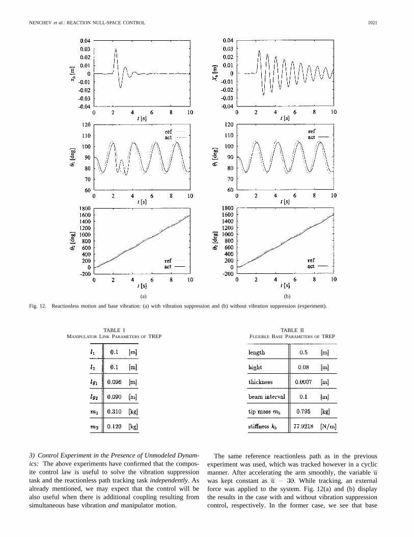
3) Control Experiment in the Presence of Unmodeled Dynam-ics: The above experiments have confirmed that the compos-ite control law is useful to solve the vibration suppressiontask and the reactionless path tracking taskindependently. Asalready mentioned, we may expect that the control will bealso useful when there is additional coupling resulting fromsimultaneous base vibrationand manipulator motion.
TABLE IIFLEXIBLE BASE PARAMETERS OF TREP
The same reference reactionless path as in the previousexperiment was used, which was tracked however in a cyclicmanner. After accelerating the arm smoothly, the variablewas kept constant as While tracking, an externalforce was applied to the system. Fig. 12(a) and (b) displaythe results in the case with and without vibration suppressioncontrol, respectively. In the former case, we see that base
1022 IEEE TRANSACTIONS ON ROBOTICS AND AUTOMATION, VOL. 15, NO. 6, DECEMBER 1999
vibration is effectively suppressed. Though, a comparison withthe case when the initial state of the manipulator was stationary[cf. the upper part of Fig. 10(a)], shows slight deteriorationin suppression performance. Of course, the arm deviatesfrom the reactionless path when suppressing the vibration,but thereafter, it quickly converges to the reference input.No instability is observed. In the other case [Fig. 12(b)], bycomparison with the upper part of Fig. 10(b), it is clearly seenthat the vibration of the base is not disturbed at all throughthe reactionless joint motion.
VIII. C ONCLUSION
The main contribution of this work are two compositecontrol laws—one acceleration based, the other torquebased—both of them capable of end-effector path trackingcontrol without inducing disturbances on the flexible base,and in addition, of base vibration suppression control. Notethat these are control subtasks two and one, respectively,as identified in the introduction. Some of the dynamicterms, e.g. nonlinear velocity-dependent coupling terms anddependencies of inertias on the elastic coordinates, havebeen ignored. Thus, complexity has been decreased, andwe obtained controls which we claim to be suitable for real-time implementation, even in the case of larger systems.Besides decreased complexity there is another merit: thecontrol gains can be selected in a straightforward mannersince the manipulator and the flexible base are considered astwo independent subsystems. Such independence is due to theorthogonal decomposition of joint space via the reaction nullspace operator. On the other hand, note that the independencemeans that, at least theoretically, the two subtasks cannot betackled simultaneously. Experiments have shown, however,that system stability ensured via the reaction null spacedecomposition seems to have a sufficiently large margin tocope with the unmodeled nonlinear dynamic effects mentionedabove, and hence, to ensure simultaneous subtask performance.The derivation of precise expressions for this stability marginis a matter of future studies. Note that such simultaneoussubtask performance means that the controls can handle thethird subtask identified in the introduction, as well.
The control laws proposed here are general enough tocover various cases of redundancy, including kinematic anddynamic redundancy, as well as redundancy due to selectivity,as introduced here. We have demonstrated via examples howthe cases of kinematic redundancy and selective redundancycan be handled. Meanwhile, we were able to tackle also thecase of dynamic redundancy, by adding a second arm to theexperimental testbed TREP. The results obtained [27] agreewell with the theories presented here.
Finally, we note that the decomposition of the dynamics bymeans of the inertia coupling matrix, as well as the analysisbased on the coupling momentum, provides insight into thephysics of the system. For example, it shows clearly that basevibration suppression in a system without energy dissipationresults in change of the coupling momentum, such that afterthe suppression the manipulator never comes to rest.
ACKNOWLEDGMENT
The authors would like to thank Dr. A. Konno, K. Abe, T.Miwa, and S. Okada for their help in designing TREP.
REFERENCES
[1] A. Sharon and D. Hardt, “Enhancement of robot accuracy using end-point feedback and a macro-micro manipulator system,” inProc. ACC,San Diego, CA, 1984, pp. 1836–1842.
[2] J. F. Jansenet al., “Long-reach manipulation for waste storage tankremediation,”ASME J., vol. 31, pp. 67–73, 1991.
[3] D.-S. Kwon et al., “Input shaping filter methods for the control ofstructurally flexible, long-reach manipulators,” inProc. IEEE Int. Conf.Robot. Automat., San Diego, CA, 1994, pp. 3259–3264.
[4] M. A. Torres and S. Dubowsky, “Path-planning in elastically constrainedspace manipulator systems,” inProc. IEEE Int. Conf. Robot. Automat.,Atlanta, GA, 1993, pp. 812–817.
[5] C. Vallancourt and C. M. Gosselin, “Compensating for the structuralflexibility of the SSRMS with the SPDM,” inProc. 2nd Workshop Robot.Space, Canadian Space Agency, Montreal, PQ, Canada, July 1994.
[6] T. Yoshikawaet al., “Quasistatic trajectory tracking control of flexiblemanipulator by macro-micro manipulator system,” inProc. 1993 IEEEInt. Conf. Robot. Automat., Atlanta, GA, May 1993, pp. 210–215.
[7] , “Dynamic trajectory tracking control of flexible manipulator bymacro-micro manipulator system,” inProc. 1994 IEEE Int. Conf. Robot.Automat., San Diego, CA, May 1994, pp. 1804–1809.
[8] W. Yim and S. N. Singh, “Nonlinear inverse and predictive end pointtrajectory control of flexible macro-micro manipulators,”Trans. ASME,J. Dyn. Syst., Meas. Contr., vol. 119, pp. 412–420, Sept. 1997.
[9] S. H. Lee and W. J. Book, “Robot vibration control using inertial damp-ing forces,” in Proc. 8th CISM–IFToMM Symp. RoManSy 8, Cracow,Poland, 1990, pp. 252–259.
[10] M. A. Torres, S. Dubowsky, and A. C. Pisoni, “Vibration control ofdeployment structures’ long-reach manipulators: The P-PED method,”in Proc. 1996 IEEE Int. Conf. Robot. Automat., Minneapolis, MN, Apr.1996, pp. 2498–2504.
[11] J. Y. Lew and D. J. Trudnowski, “Vibration control of a micro/macromanipulator system,”IEEE Contr. Syst. Mag., vol. 16, no. 1, pp. 26–31,Feb. 1996.
[12] I. Sharf, “Active damping of a large flexible manipulator with a short-reach robot,”Trans. ASME, J. Dyn. Syst., Meas. Contr., vol. 118, pp.704–713, Dec. 1996.
[13] D. W. Cannonet al., “Experimental study on micro/macro manipulatorvibration control,” inProc. IEEE Int. Conf. Robot. Automat., Minneapo-lis, MN, 1996, pp. 2549–2554.
[14] R. H. Cannon, Jr. and E. Schmitz,“ Initial experiments on the end-pointcontrol of a flexible one-link robot,”Int. J. Robot. Res., vol. 3, no. 3,pp. 62–75, 1984.
[15] C. Mavroidis, S. Dubowsky, and V. Raju, “End-point control of longreach manipulator systems,” inProc. 9th World Congr. IFToMM, Mi-lano, Italy, 1995, pp. 1740–1744.
[16] M. L. Hanson and R. H. Tolson, “Reducing flexible base vibrationsthrough local redundancy resolution,”J. Robot. Syst., vol. 12, no. 11,pp. 767–779, 1995.
[17] T. Arai et al., “Proposal of dynamic redundancy in robot control,” inProc. IEEE/RSJ Int. Workshop Intell. Robots Syst. (IROS’92), Raleigh,NC, 1992, pp. 1921–1926.
[18] D. N. Nenchev, K. Yoshida, and Y. Umetani, “Analysis, design andcontrol of free-flying space robots using fixed-attitude-restricted Jaco-bian matrix,”Robotics Research: The Fifth International Symposium, H.Miura and S. Arimoto, Eds. Cambridge, MA: MIT Press, 1990, pp.251–258.
[19] D. N. Nenchev, Y. Umetani, and K. Yoshida, “Analysis of a redun-dant free-flying spacecraft/manipulator system,”IEEE Trans. Robot.Automat., vol. 8, pp. 1–6, Feb. 1992.
[20] D. N. Nenchev, “A controller for a redundant free-flying space robotwith spacecraft attitude/manipulator motion coordination,” inProc. 1993IEEE/RSJ Int. Conf. Intell. Robots Syst. (IROS’93), Yokohama, Japan,1993, pp. 2108–2114.
[21] A. Konno et al., “Configuration-dependent vibration controllability offlexible-link manipulators,” Int. J. Robot. Res., vol. 16, no. 4, pp.567–576, 1997.
[22] K. Yoshida, D. N. Nenchev, and M. Uchiyama, “Moving base roboticsand reaction management control,”Robotics Research: The SeventhInternational Symposium, G. Giralt and G. Hirzinger, Eds. New York:Springer-Verlag, 1996, pp. 101–109.
NENCHEV et al.: REACTION NULL-SPACE CONTROL 1023
[23] K. Yoshida and D. N. Nenchev, “A general formulation of under-actuated manipulator systems,” inPreprints 8th Int. Symp. RoboticsResearch, Hayama, Japan, 1997, pp. 72–79.
[24] D. N. Nenchev, K. Yoshida, and M. Uchiyama, “Reaction null-spacebased control of flexible structure mounted manipulating systems,” inProc. 35th IEEE CDC, Kobe, Japan, 1996, pp. 4118–4123.
[25] A. Isidori, Nonlinear Control Systems, 3rd ed. New York: Springer-Verlag, 1995.
[26] D. N. Nenchev, “Restricted Jacobian matrices of redundant manipulatorsin constrained motion tasks,”Int. J. Robot. Res., vol. 11, no. 6, pp.584–597, 1993.
[27] A. Gouoet al., “Dual-arm long-reach manipulators: Noncontact motioncontrol startegies,” inProc. IEEE/RSJ Int. Conf. Intell. Robots Syst.(IROS’98), Victoria, B.C., Canada, Oct. 1998, pp. 449–454.
Dragomir N. Nenchev (M’92) received the B.Eng.degree in computer science, the M.Eng. degree, andthe Ph.D. degree in robotics, all from the HigherInstitute of Electrical and Mechanical Engineering(now Technical University), Sofia, Bulgaria in 1979,1981, and 1985, respectively.
He has been with the Robotics Department, Tech-nical University of Sofia, and with the Depart-ment of Aeronautics and Space Engineering, To-hoku University, Sendai, Japan, and the Departmentof Mechanical and Production Engineering, Niigata
University, Japan. He is now Professor with the Department of IntelligentMachines and System Engineering, Hirosaki University, Hirosaki, Japan.He was also a Visiting Researcher with the Department of MechanicalEngineering Science, Tokyo Institute of Technology, Tokyo, Japan, from 1988to 1989, and the Department of Mechanics, Milan Polytechnic, Italy, from1992 to 1993. His research interests are in kinematics, dynamics and motioncontrol of underactuated, parallel, and redundant robot systems.
Kazuya Yoshida (M’91) received the B.Eng.,M.Eng., and Dr.Eng. degrees from the TokyoInstitute of Technology, Tokyo, Japan, in 1984,1986 and 1990, respectively.
From 1986 to 1994, he was with Departmentof Mechanical Engineering of Science (Mechano-Aerospace), Tokyo Institute of Technology, Tokyo,as a Research Associate. During this period,he stayed with the Swiss Federal Institute ofTechnology (ETH) in September 1993, and withthe Massachusetts Institute of Technology (MIT),
Cambridge, from March 1994 to March 1995, as a Visiting Scientist. Since1995 he has been an Associate Professor in the Department of Aeronautics andSpace Engineering, Tohoku University, Sendai, Japan. His current interestsinclude the dynamics and control of both free-flying and elastically mountedspace manipulators, and the design and dynamic analysis of planetaryexploration robots.
Prasert Vichitkulsavat received the B.Eng. andM.Eng. degrees from Tohoku University, Sendai,Japan, in 1994 and 1996, respectively. The researchwork presented in this paper was performed as hisM.Eng. thesis.
He was with Siam-Hitachi Elevator Co., Ltd., andThai Ikeda Mfg. Co., Ltd., and T. Nongkarm A.Sriracha Chonburi, Thailand.
Masaru Uchiyama (M’79) received the B.Eng.,M.Eng., and Ph.D. degrees from the University ofTokyo, Tokyo, Japan, in 1972, 1974, and 1977,respectively, all in mechanical engineering.
Since 1977, he has been with the School ofEngineering, Tohoku University, Sendai, Japan andcurrently is a Professor of the Spacecraft SystemsLaboratory, Department of Aeronautics and SpaceEngineering. He was a Visiting Fellow at the Uni-versity of Newcastle upon Tyne, U.K., from 1982to 1983, and a Visiting Professor at the University
of California, Santa Barbara, from 1986 to 1987. Currently he is a VisitingProfessor at the Institute of Space and Astronautical Science, Japan, sinceApril 1999. His research interests are manipulation robotics and its applicationto aerospace engineering.