Re: Request for Quote – Jordan Narrows Automation Project ... Narrows Automation Project...
33
February 7, 2017 Re: Request for Quote – Jordan Narrows Automation Project Jordan Narrows Pumping Plant Bluffdale, Utah The Provo River Water Users Association (Owner), in cooperation with AE2S (Engineer) is requesting quotes for the installation of electrical components to facilitate the automation of new Owner-furnished valve actuators, an existing Owner-operated valve actuator, and automatic oiler system. The quote shall comply with the requirements described in this letter and the attached project specifications. Please note the following: • The term “bid” or “bidder” used in the specifications are interchangeable with the terms “quote or “quoter”. • Familiarity with the site conditions is a requirement of submitting a quote. A mandatory pre-quote site visit is scheduled for Thursday February 9, 2017 at 3:00 p.m. local time. Scope of Work Jordan Narrows Automation Project electrical upgrades including a new lighting panelboard, power control and signal circuitry to the 4 new electrically actuated valves, control circuitry to the automatic oiler and the existing electrically actuated valve, and all other items as indicated on the drawings. • Mobilization/Demobilization • Furnish and install new panelboard and associated control/signal circuitry, including the following: o Install/modify the existing lighting panel for the addition of 60A-240V/3 Breaker; including circuitry to the new LP. o A new 22 space lighting panel to feed 3 phase power to the new Owner furnished actuators. o Control and signal circuitry between the actuators and the existing control panel. o 2 new wall mounted junction boxes for the marshalling of actuator control and signal circuitry back to the control panel. o Control circuitry between the automatic oiler and control panel. • Demonstration and testing assistance of the equipment with Owner and Engineer. • Note that all conduit shall be mounted off walls and ceilings using galvanized unistrut. • See drawings for additional details.
Transcript of Re: Request for Quote – Jordan Narrows Automation Project ... Narrows Automation Project...

February 7, 2017 Re: Request for Quote – Jordan Narrows Automation Project Jordan Narrows Pumping Plant Bluffdale, Utah The Provo River Water Users Association (Owner), in cooperation with AE2S (Engineer) is requesting quotes for the installation of electrical components to facilitate the automation of new Owner-furnished valve actuators, an existing Owner-operated valve actuator, and automatic oiler system. The quote shall comply with the requirements described in this letter and the attached project specifications. Please note the following:
• The term “bid” or “bidder” used in the specifications are interchangeable with the terms “quote or “quoter”.
• Familiarity with the site conditions is a requirement of submitting a quote. A mandatory pre-quote site visit is scheduled for Thursday February 9, 2017 at 3:00 p.m. local time.
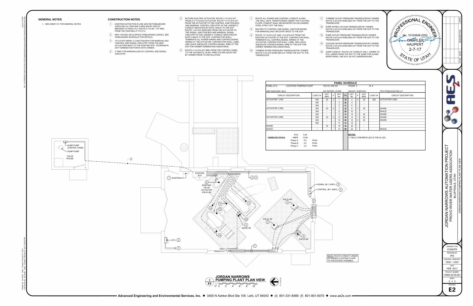
Scope of Work Jordan Narrows Automation Project electrical upgrades including a new lighting panelboard, power control and signal circuitry to the 4 new electrically actuated valves, control circuitry to the automatic oiler and the existing electrically actuated valve, and all other items as indicated on the drawings.
• Mobilization/Demobilization
• Furnish and install new panelboard and associated control/signal circuitry, including the following:
o Install/modify the existing lighting panel for the addition of 60A-240V/3 Breaker; including circuitry to the new LP.
o A new 22 space lighting panel to feed 3 phase power to the new Owner furnished actuators.
o Control and signal circuitry between the actuators and the existing control panel. o 2 new wall mounted junction boxes for the marshalling of actuator control and
signal circuitry back to the control panel. o Control circuitry between the automatic oiler and control panel.
• Demonstration and testing assistance of the equipment with Owner and Engineer.
• Note that all conduit shall be mounted off walls and ceilings using galvanized unistrut.
• See drawings for additional details.

Request for Quote – Jordan Narrows Automation Project February 7, 2017
It is the intention of this scope of work to call for finished work, tested, and ready for operation. Wherever the work "provide" is used, it shall mean "furnish and install complete and ready for use." Demonstration Testing - Upon completion of the installation, the Contractor shall demonstrate that each separate piece of equipment of each system operates as specified. Project Deliverables / Submittals Contractor shall furnish Owner and Engineer with a written report certifying that equipment has been properly installed; is in accurate alignment and calibration; is free from undue stress imposed by interconnecting cable/conduit; and has been operated and demonstrated to the Owner that it operates satisfactorily under expected conditions. All other submittal requirements as defined in the attached project specifications. Warranty Panelboard and related equipment shall be warranted against defects in workmanship and materials for a period of two (2) years. Warranty period shall begin upon final completion of the project per the satisfactory completion of the actuator demonstration test following installation of the electrical components. Project Schedule The anticipated timeline for the project is shown below. The Owner reserves the right to assess liquidated damages for each calendar day the work extends beyond the stated project completion deadline. Issue RFQ February 7, 2017
Mandatory Pre-Quote Site Visit February 9, 2017 – 3:00 p.m. local time
Quote Submittal Deadline February 15, 2017 – 10:00 a.m. local time
Contract Award & Execution February 16, 2017
Project Commencement March 6, 2017
Final Completion* March 15, 2017
*Final Completion is defined as all work completed and ready for final payment. Addenda to the Bid The provisions of this bid cannot be modified by oral interpretations or statements. If inquiries or comments by bidders require clarification by the Engineer, or if the Engineer revises any part of this request for bids, addenda will be provided to all persons known to the contact person who have received or will subsequently receive the request for bids. Receipt of any addenda must be acknowledged on the bid form in the project specifications. Bid Schedule Bids must be submitted using the attached bid form in a sealed envelope bearing on the outside the name of the bidder, full company address, name of the project for which the bid is submitted, and shall be delivered, mailed, or emailed to the following address:
Request for Quote – Jordan Narrows Automation Project February 7, 2017
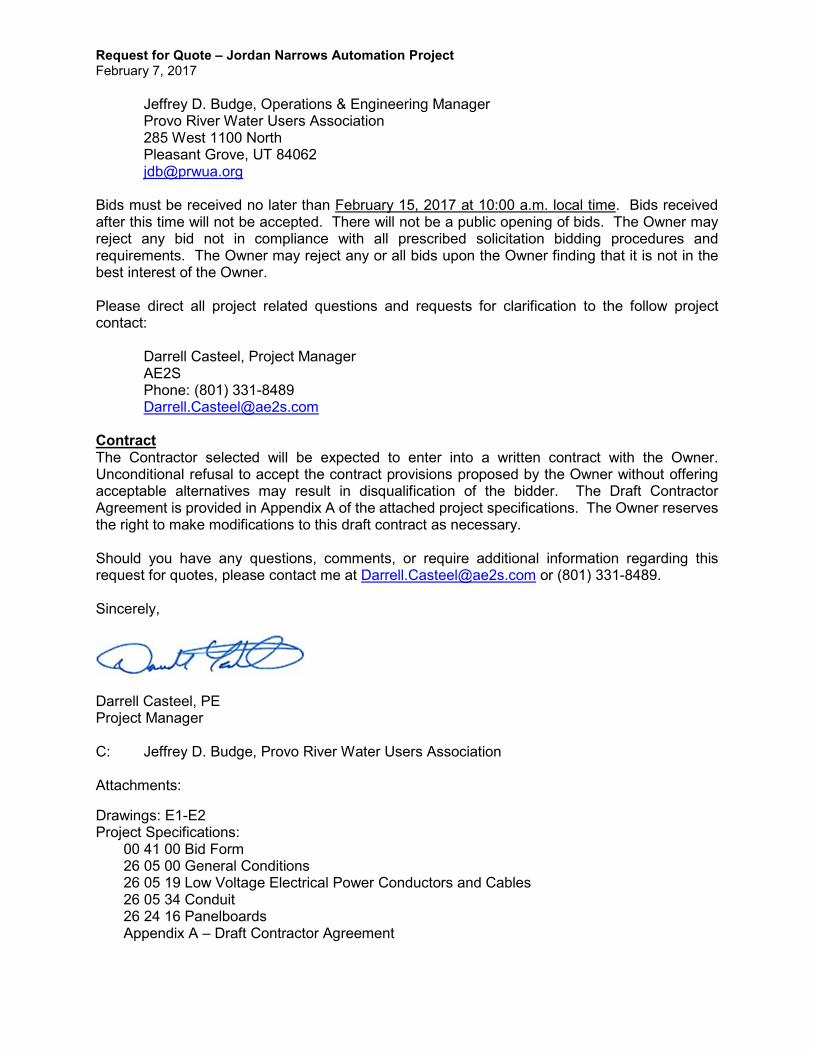
Jeffrey D. Budge, Operations & Engineering Manager Provo River Water Users Association 285 West 1100 North Pleasant Grove, UT 84062 [email protected] Bids must be received no later than February 15, 2017 at 10:00 a.m. local time. Bids received after this time will not be accepted. There will not be a public opening of bids. The Owner may reject any bid not in compliance with all prescribed solicitation bidding procedures and requirements. The Owner may reject any or all bids upon the Owner finding that it is not in the best interest of the Owner. Please direct all project related questions and requests for clarification to the follow project contact:
Darrell Casteel, Project Manager AE2S Phone: (801) 331-8489 [email protected] Contract The Contractor selected will be expected to enter into a written contract with the Owner. Unconditional refusal to accept the contract provisions proposed by the Owner without offering acceptable alternatives may result in disqualification of the bidder. The Draft Contractor Agreement is provided in Appendix A of the attached project specifications. The Owner reserves the right to make modifications to this draft contract as necessary. Should you have any questions, comments, or require additional information regarding this request for quotes, please contact me at [email protected] or (801) 331-8489. Sincerely,
Darrell Casteel, PE Project Manager C: Jeffrey D. Budge, Provo River Water Users Association Attachments:
Drawings: E1-E2 Project Specifications:
00 41 00 Bid Form 26 05 00 General Conditions 26 05 19 Low Voltage Electrical Power Conductors and Cables 26 05 34 Conduit 26 24 16 Panelboards Appendix A – Draft Contractor Agreement
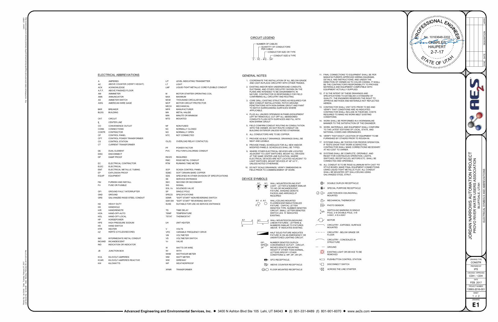
CONDUIT SIZE & TYPE
CONDUCTOR SIZE OR TYPE
QUANTITY OF CONDUCTORS
2 - 1/C - #12 - 3/4"
NUMBER OF CABLES
PER CABLE
CIRCUIT LEGEND
WALL MOUNTED/CEILING EXIT
LIGHT - LETTER & NUMBER SIMILAR
TO HID OR INCANDESCENT
FIXTURE, SHADING DENOTE
FACE(S) AND ARROW(S) IF
REQUIRED
WALL/CEILING MOUNTED
FLUORESCENT/INDUCTION/LED
FIXTURE - CAPITAL LETTER
DENOTES TYPE, NUMBER DENOTES
CIRCUIT, SMALL LETTER DENOTES
SWITCH LEG. 'E' INDICATES
EXISTING.
WALL MOUNTED/CEILING/HUNG
LINEAR FIXTURES - LETTERS &
NUMBERS SIMILAR TO FIXTURES
ABOVE. 'E' INDICATES EXISTING.
HALF SOLID FIXTURE INDICATES
FIXTURE IS ON AN EMERGENCY OR
UNSWITCHED LIGHTING CIRCUIT.
NUMBER DENOTES DUPLEX
CONVENIENCE OUTLET - CIRCUIT,
INCHES DENOTE MOUNTING
HEIGHT IF OTHER THAN NORMAL,
LETTERS SPECIFY OTHER
CONDITIONS ie: WP, DP, OR GFI.
GFCI RECEPTACLE.
ABOVE COUNTER RECEPTACLE
FLOOR MOUNTED RECEPTACLE
GFI
WP
24''
A/1
d A/1 d
X/1X/1
A/1 d A/1
E
E
3
a
PS
J J
T
DOUBLE DUPLEX RECEPTACLE
SPECIAL PURPOSE RECEPTACLE
JUNCTION BOX-CEILING/WALL
MOUNTED
MECHANICAL THERMOSTAT
PHOTO SENSOR
SWITCH-NO MARKING IS SINGLE
POLE, 2 IS DOUBLE POLE, 3 IS
3-WAY, 4 IS 4-WAY
MOTOR
CIRCUITRY - EXPOSED, SURFACE
MOUNTED
CIRCUITRY - BELOW GRADE OR
FLOOR
CIRCUITRY - CONCEALED IN
STRUCTURE
GROUND
EXISTING LIGHT OR DEVICE TO BE
REMOVED
PUSHBUTTON CONTROL STATION
DISCONNECT SWITCH
ACROSS THE LINE STARTER
DEVICE SYMBOLS
ELECTRICAL ABBREVIATIONS
A AMPERES LIT LEVEL INDICATING TRANSMITTER
AC
ABOVE COUNTER (VERIFY HEIGHT)
LT LIGHT
ACK ACKNOWLEDGE LMF LIQUID-TIGHT METALLIC CORE FLEXIBLE CONDUIT
A.F.F. ABOVE FINISHED FLOOR
AM AMMMETER M MOTOR STARTER OPERATING COIL
ANN ANNUNCIATOR MAX MAXIMUM
AS AMMETER SWITCH MCM THOUSAND CIRCULAR MILS
AWG AMERICAN WIRE GAGE MCP MOTOR CIRCUIT PROTECTOR
MECH MECHANICAL
BKR BREAKER MFR MANUFACTURER
BLDG BUILDING MH METAL HALIDE
MIN MINUTE OR MINIMUM
CKT CIRCUIT MTD MOUNTED
℄ CENTER LINE
CO CONVENIENCE OUTLET NF NON-FUSED
CONN CONNECTIONS NC NORMALLY CLOSED
CONTR CONTRACTOR NO NORMALLY OPEN
CP CONTROL PANEL NTC NOT CONNECTED
CPT CONTROL POWER TRANSFORMER
CS CONTROL STATION
OL(S) OVERLOAD RELAY CONTACT(S)
CT CURRENT TRANSFORMER
PF POWER FACTOR
DE DUAL ELEMENT PVC POLYVINYLCHLORIDE CONDUIT
DISC DISCONNECT
DP DAMP PROOF REQ'D REQUIRED
RMC RIGID METAL CONDUIT
EC ELECTRICAL CONTRACTOR RTM RUNNING TIME METER
ELEC ELECTRICAL
EMT ELECTRICAL METALLIC TUBING SCP SCADA CONTROL PANEL
EP EXPLOSION PROOF SDBC SOFT DRAWN BARE COPPER
EQUIP EQUIPMENT SDS SPECIFIED IN OTHER DIVISION OF SPECIFICATIONS
SE SERVICE ENTRANCE
F&I FURNISH AND INSTALL SEC SECOND OR SECONDARY
FU FUSE OR FUSIBLE SIG SIGNAL
SOL Vv SOLENOID VALVE
GFI GROUND FAULT INTERRUPTER SP SINGLE POLE
GND GROUND SPECS SPECIFICATIONS
GRS GALVANIZED RIGID STEEL CONDUIT SSNR ''SOFT START'' NON-REVERSING SWITCH
SSR SW ''SOFT START'' REVERSING SWITCH
HD HEAVY DUTY SUSE SUITABLE FOR USE AS SERVICE ENTRANCE
HH HANDHOLE
H/R HAND/REMOTE TD TIME DELAY
HOA HAND-OFF-AUTO TEMP TEMPERATURE
HOL HAND-OFF-LOCAL TSTAT THERMOSTAT
HP HORSEPOWER
HPS HIGH PRESSURE SODIUM UH UNIT HEATER
HS HAND SWITCH
HTR HEATER V VOLTS
HZ
HERTZ (CYCLES/SECOND)
VFD VARIABLE FREQUENCY DRIVE
VM VOLTMETER
IMC INTERMEDIATE METAL CONDUIT VS VOLTMETER SWITCH
INCAND INCANDESCENT Vv VALVE
IND INDICATION OR INDICATOR
W WATTS OR WIRE
JB JUNCTION BOX W/ WITH
WHM WATTHOUR METER
KVA KILOVOLT-AMPERES WM WATT METER
KVAR KILOVOLT-AMPERES REACTIVE WW WIREWAY
KW KILOWATTS WP WEATHERPROOF
XFMR TRANSFORMER
GENERAL NOTES
1. COORDINATE THE INSTALLATION OF ALL BELOW-GRADE
AND CAST-IN-PLACE CIRCUITRY WITH OTHER TRADES.
2. EXISTING AND/OR NEW UNDERGROUND CONDUITS,
DUCTBANK, AND OTHER CIRCUITRY SHOWN ON THE
PLANS ARE INTENDED TO BE DIAGRAMMATIC IN
NATURE. CONTRACTOR IS RESPONSIBLE FOR FIELD
CONFIRMING ALL CIRCUITRY AND ROUTING.
3. CORE DRILL EXISTING STRUCTURES AS REQUIRED FOR
NEW CONDUIT INSTALLATIONS. PATCH AROUND
PENETRATIONS WITH NON-SHRINK GROUT AND PAINT
TO MATCH SURROUNDING SURFACES WHERE
APPLICABLE.
4. PLUG ALL UNUSED OPENINGS IN PANELS/EQUIPMENT
LEFT BY REMOVALS, CUT OFF ALL ABANDONED
CONDUITS FLUSH WITH SURFACES AND FILL WITH
NON-SHRINK GROUT
5. FIELD CONFIRM CONDUIT ROUTING IN CONSULTATION
WITH THE OWNER. DO NOT ROUTE CONDUIT ON
BUILDING EXTERIOR UNLESS NOTED OTHERWISE.
6. ALL CONDUCTORS ARE TO BE COPPER.
7. PROVIDE AS BUILT DRAWINGS. DRAWINGS SHALL BE
NEAT AND LEGIBLE.
8. PROVIDE PANEL SCHEDULES FOR ALL NEW AND/OR
MODIFIED PANELS. SCHEDULES SHALL BE TYPED.
9. WHERE OTHER ELECTRICAL DEVICES ARE LOCATED
ADJACENT TO LIGHT SWITCHES, MOUNT ALL DEVICES
AT THE SAME CENTER LINE ELEVATION. WHERE
ELECTRICAL DEVICES ARE NOT LOCATED ADJACENT TO
LIGHT SWITCHES, MOUNT DEVICES AT 48'' A.F.F.,
UNLESS NOTED OTHERWISE.
10. DO NOT SCALE DRAWINGS. VERIFY DIMENSIONS IN
FIELD PRIOR TO COMMENCEMENT OF WORK.
11. FINAL CONNECTIONS TO EQUIPMENT SHALL BE PER
MANUFACTURER'S APPROVED WIRING DIAGRAMS,
DETAILS, AND INSTRUCTIONS, AND UNDER THE
DIRECTION OF OWNER AS TO COLOR CODING. IT SHALL
BE THE CONTRACTOR'S RESPONSIBILITY TO PROVIDE
MATERIALS AND EQUIPMENT COMPATIBLE WITH
EQUIPMENT ACTUALLY SUPPLIED.
12. IT IS THE INTENT OF THESE DRAWINGS AND
SPECIFICATIONS TO ESTABLISH A STANDARD OF
QUALITY. THE ENGINEER RESERVES THE RIGHT TO
APPROVE METHODS AND MATERIALS NOT REFLECTED
HEREIN.
13. CONTRACTOR SHALL VISIT SITE PRIOR TO BID AND
VERIFY THAT CONDITIONS ARE AS INDICATED.
CONTRACTOR SHALL INCLUDE IN THEIR BID, COSTS
REQUIRED TO MAKE HIS WORK MEET EXISTING
CONDITIONS.
14. WORK SHALL BE PERFORMED IN A WORKMANLIKE
MANNER TO THE SATISFACTION OF THE ENGINEER.
15. WORK, MATERIALS, AND EQUIPMENT SHALL CONFORM
TO THE LATEST EDITIONS OF LOCAL, STATE, AND
NATIONAL CODES AND ORDINANCES.
16. VERIFY THAT EXACT LOCATION OF EQUIPMENT TO BE
FURNISHED BY OTHERS PRIOR TO ROUGH-IN.
17. SYSTEMS SHALL BE TESTED FOR PROPER OPERATION.
IF TESTS SHOW THAT WORK IS DEFECTIVE,
CONTRACTOR SHALL MAKE CORRECTIONS NECESSARY
AT NO COST TO OWNER.
18. SYSTEMS SHALL BE COMPLETE, OPERABLE, AND
READY FOR CONTINUOUS OPERATION. LIGHTS,
SWITCHES, RECEPTACLES, MOTORS ETC. SHALL BE
CONNECTED AND OPERABLE.
19. ALL CONDUIT IS TO BE RIGID ALUMINUM WITH CAST 'FS'
STYLE BOXES. MAKE FINAL EQUIPMENT CONNECTIONS
USING LIQUID-TIGHT METALLIC FLEX. ALL CONDUIT
SHALL BE MOUNTED OFF WALL/CEILING USING
GALVANIZED STEEL STRUT.
File: W
:\P
\P
RW
UA
\13993-2016-001\C
AD
D
wgs\06-E
lectrical\A
utocad\P
lan S
heets\E
-S
ym
bols and A
bbreviations.dw
gLast S
aved: B
y: Ian S
mith D
ate: M
onday, F
ebruary 06, 2017 5:07:37 P
M
Plotted: B
y: Ian S
mith D
ate: T
uesday, F
ebruary 07, 2017
Layout: LG
ND
1
SHEET
PROJECT NUMBER
CHECKED / APPROVED
DATE
DRAWING TYPE
PREPARED BY
of
SY
MD
AT
ED
ES
CR
IP
TIO
NA
PP
R
DRAWING
/
Advanced Engineering and Environmental Services, Inc. l 3400 N Ashton Blvd Ste 105 Lehi, UT 84043 l (t) 801-331-8489 (f) 801-901-6070 l www.ae2s.com
JO
RD
AN
N
AR
RO
WS
A
UT
OM
AT
IO
N P
RO
JE
CT
PR
OV
O R
IV
ER
W
AT
ER
U
SE
RS
A
SS
OC
IA
TIO
N
BLU
FF
DA
LE
, U
TA
H
ELE
CT
RIC
AL S
YM
BO
LS
A
ND
A
BB
RE
VIA
TIO
NS
CONSTR
IPS
CDH CDH
FEB. 2017
13993-2016-001
1 2
E1
No. 10163648-2202
CHARLES
HAUPERT
P
R
O
F
E
S
S
IO
NA
L
E
N
G
I
N
E
E
R
P
R
O
F
E
S
S
IO
NA
L
E
N
G
I
N
E
E
R
S
T
A
T
E
OF
U
T
A
H
2-7-17
N
H
RO
T
1
E2
JORDAN NARROWS
PUMPING PLANT PLAN VIEW
12"
0 2' 4' 6' 8' 10'
GENERAL NOTES
1. SEE SHEET E1 FOR GENERAL NOTES.
5
5
5
240/3
FROM LP-2
LP-2
EXISTING LP
EXISTING
SCP
SIGNAL JB-1 (300V)
CONTROL JB-1 (600V)
2
1
3
3
4
PANEL SCHEDULE
PANEL:LP-2 LOCATION: PUMPING PLANT VOLTS: 240/120 PHASE: 3 W: 4
AMP MAIN BKR: MLOAIC RATING: 22,000
MOUNT: SURFACE FED FROM:EXISTING LP
CIRCUIT DESCRIPTION LOAD VA
CKT.
BKR.
P
CKT.
No.
PH.
CKT.
No.
P
CKT.
BKR.
LOAD VA CIRCUIT DESCRIPTION
ACTUATOR 1 (1M)
500 20 3 1 A 2 3 20 500
ACTUATOR 5 (5M)
- 500 - - 3 B 4 - - -
- 500 - - 5 C 6 - - -
ACTUATOR 3 (3M)
500 20 3 7 A 8 1 20 SPARE
- 500 - - 9 B 10 - - SPACE
- 500 - - 11 C 12 1 20 SPARE
ACTUATOR 4 (4M)
500 20 3 13 A 14 1 20 SPARE
- 500 - - 15 B 16 3 20 SPARE
- 500 - - 17 C 18 - - -
SPARE - 20 1 19 A 20 - - -
SPACE - - - 21 B 22 - - SPACE
CONNECTED TOTALS:
KVA 5.00NOTES:
AMPS 13.88 1. FIELD CONFIRM B LEG IS THE HI LEG
Phase A 5.6
Amps
Phase B 4.2
Amps
Phase C 4.2
Amps
7
5
6
File: W
:\P
\P
RW
UA
\13993-2016-001\C
AD
D
wgs\06-E
lectrical\A
utocad\P
lan S
heets\E
-B
uilding P
lan.dw
gLast S
aved: B
y: Ian S
mith D
ate: T
uesday, F
ebruary 07, 2017 2:38:25 P
M
Plotted: B
y: Ian S
mith D
ate: T
uesday, F
ebruary 07, 2017
Layout: P
LA
N2
SHEET
PROJECT NUMBER
CHECKED / APPROVED
DATE
DRAWING TYPE
PREPARED BY
of
SY
MD
AT
ED
ES
CR
IP
TIO
NA
PP
R
DRAWING
/
Advanced Engineering and Environmental Services, Inc. l 3400 N Ashton Blvd Ste 105 Lehi, UT 84043 l (t) 801-331-8489 (f) 801-901-6070 l www.ae2s.com
JO
RD
AN
N
AR
RO
WS
A
UT
OM
AT
IO
N P
RO
JE
CT
PR
OV
O R
IV
ER
W
AT
ER
U
SE
RS
A
SS
OC
IA
TIO
N
BLU
FF
DA
LE
, U
TA
H
JO
RD
AN
N
AR
RO
WS
P
UM
PIN
G P
LA
NT
P
LA
N V
IE
W
CONSTR
IPS
CDH CDH
FEB. 2017
13993-2016-001
2 2
E2
S36-ZI-5M
S36-ZI-4M
S36-ZI-3M
S36-ZI-1M
7
~
7
NOTE: ROUTE CONDUIT UNDER
EXTENDED FLOATING FLOOR
TO THE EXTENT POSSIBLE.
8
EXISTING
VALVE
ACTUATOR
S36-ZI-2M
9
10
11
12
14
13
SUMP PUMP
CONTROL PANEL
VALVE
HOUSE
15
SUMP PUMP
CONSTRUCTION NOTES
EXISTING EATON POW-R-LINE 240V/3Ø PANELBOARD
(OPEN DELTA). PROVIDE A NEW 60A/3P CIRCUIT
BREAKER TO FEED LP-2. ROUTE 5-1/C-#4-1 1/4" RMC
FROM THE EXISTING LP TO LP-2.
NEW 120/240V-3Ø 22-SPACE PANELBOARD (22KAIC). SEE
PANELBOARD SCHEDULE FOR DETAILS.
12"x12"x6"D NEMA 12 JUNCTION BOX FOR MARSHALLING
CONTROL AND SIGNAL CIRCUITRY FROM THE NEW
ACTUATORS BACK TO THE EXISTING SCP. COORDINATE
SCP TERMINATION POINTS WITH OWNER.
2" RMC FOR MARSHALLING OF CONTROL AND SIGNAL
CIRCUITRY.
ROTORK ELECTRIC ACTUATOR. ROUTE 3-1/C-#12-3/4"
FROM LP-2 TO EACH ACTUATOR. ROUTE 14-1/C-#14-3/4"
FROM THE ACTUATOR TO THE CONTROL JUNCTION BOX
AND MARSHAL CONTROL CIRCUITRY IN THE LARGER 2"
CONDUIT INDICATED BY NOTE 4 BACK TO THE SCP.
ROUTE 1-2/C-#16 SHIELDED FROM THE ACTUATOR TO
THE SIGNAL JUNCTION BOX AND MARSHAL SIGNAL
CIRCUITRY IN THE LARGER 2" CONDUIT INDICATED BY
NOTE 4 BACK TO THE SCP. CONTRACTOR SHALL
TERMINATE ALL POWER WIRING AND CONTROL/SIGNAL
WIRING AT THE ACTUATOR. CONTRACTOR SHALL LABEL
AND LEAVE ADEQUATE CONTROL/SIGNAL WIRE AT THE
SCP FOR OWNER TERMINATING ASSISTANCE.
ROUTE 4-1/C-#14-3/4" RMC FROM THE CONTROL PANEL
TO THE AUTOMATIC OILER. WIRE COLORS SELECTED
BY OWNER PRIOR TO INSTALLATION.
ROUTE ALL POWER AND CONTROL CONDUIT ALONG
THE WALL UNTIL TRANSITIONING UNDER THE FLOATING
FLOOR. CONDUIT SHALL BE MOUNTED ON GALVANIZED
STEEL STRUT OFF THE WALL.
ROUTED TO CONTROL AND SIGNAL JUNCTION BOXES
FOR MARSHALLING CIRCUITRY BACK TO THE SCP.
ROUTE 14-1/C-#14-3/4" AND 1-2/C-#16-3/4" FROM THE
EXISTING ACTUATOR TO THE SCP. CONTRACTOR SHALL
TERMINATE ALL CONTROL/SIGNAL WIRING AT THE
ACTUATOR. CONTRACTOR SHALL LABEL AND LEAVE
ADEQUATE CONTROL/SIGNAL WIRE AT THE SCP FOR
OWNER TERMINATING ASSISTANCE.
TURBINE INTAKE PRESSURE TRANSDUCER BY OWNER.
ROUTE 2-2/C-#16 SHIELDED-3/4" FROM THE SCP TO THE
TRANSDUCER.
TURBINE OUTLET PRESSURE TRANSDUCER BY OWNER.
ROUTE 2-2/C-#16 SHIELDED-3/4" FROM THE SCP TO THE
TRANSDUCER.
PUMP INTAKE VACUUM TRANSDUCER BY OWNER.
ROUTE 2-2/C-#16 SHIELDED-3/4" FROM THE SCP TO THE
TRANSDUCER.
PUMP OUTLET PRESSURE TRANSDUCER BY OWNER.
ROUTE 2-2/C-#16 SHIELDED-3/4" FROM THE SCP TO THE
TRANSDUCER.
COOLING WATER PRESSURE TRANSDUCER BY OWNER.
ROUTE 2-2/C-#16 SHIELDED-3/4" FROM THE SCP TO THE
TRANSDUCER.
SUMP CONDUIT. ROUTE 3/4" CONDUIT ONLY, OWNER TO
PULL WIRES FROM THE SCP TO THE SUMP FOR ALARM
MONITORING. USE SCH. 80 PVC UNDERGROUND.
1
2
3
4
5
6
7
8
9
10
11
12
13
14
15
No. 10163648-2202
CHARLES
HAUPERT
P
R
O
F
E
S
S
IO
NA
L
E
N
G
I
N
E
E
R
P
R
O
F
E
S
S
IO
NA
L
E
N
G
I
N
E
E
R
S
T
A
T
E
OF
U
T
A
H
2-7-17

Advanced Engineering and Environmental Services, Inc. 3400 North Ashton Blvd, Suite 105 Lehi, Utah 84043 Ph: 801-331-8489 Fax: 801-901-6070 Web: www.AE2S.com
JORDAN NARROWS AUTOMATION PROJECT
PREPARED FOR:
Provo River Water Users Association
AE2S Project No. P13993-2016-001
February 2017
P R O J E C T S P E C I F I C AT I O N S
Jordan Narrows Automation Project - PRWUA
00 01 05 - 1 Professional Certification
SECTION 00 01 05 - PROFESSIONAL CERTIFICATION
ELECTRICAL ENGINEER
I hereby certify that the following portions of this Specification were prepared by me, or under my direct supervision, and that I am a duly Registered Engineer under the laws of the State of Utah.
_____________________________________________________________
Charles Haupert, PE, AE2S, Inc. DATE: 2/7/17 REG. NO. 10163648-2202
END OF CERTIFICATION PAGE
No. 10163648-2202
CHARLES
HAUPERT
P
R
O
F
E
S
S
IO
NA
L
E
N
G
I
N
E
E
R
P
R
O
F
E
S
S
IO
NA
L
E
N
G
I
N
E
E
R
S
T
A
T
E
OF
U
T
A
H
2-7-17
Jordan Narrows Automation Project PRWUA 00 41 00 - 1 Bid Form
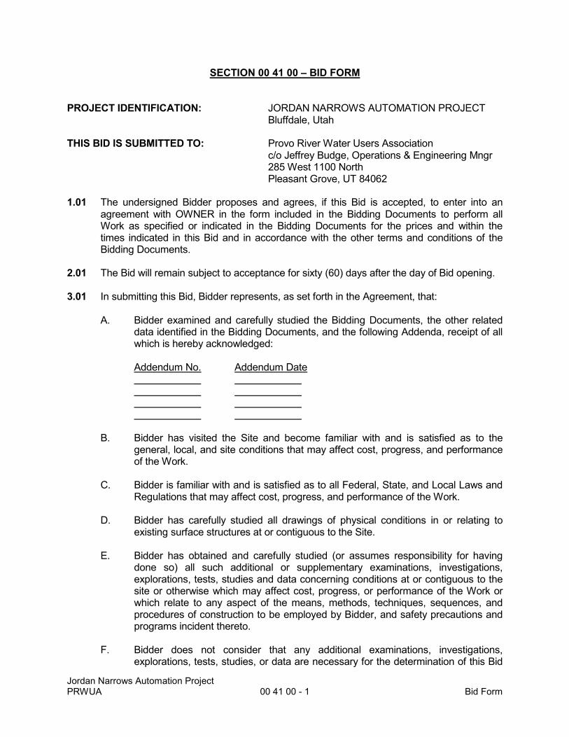
SECTION 00 41 00 – BID FORM PROJECT IDENTIFICATION: JORDAN NARROWS AUTOMATION PROJECT Bluffdale, Utah THIS BID IS SUBMITTED TO: Provo River Water Users Association c/o Jeffrey Budge, Operations & Engineering Mngr 285 West 1100 North
Pleasant Grove, UT 84062 1.01 The undersigned Bidder proposes and agrees, if this Bid is accepted, to enter into an
agreement with OWNER in the form included in the Bidding Documents to perform all Work as specified or indicated in the Bidding Documents for the prices and within the times indicated in this Bid and in accordance with the other terms and conditions of the Bidding Documents.
2.01 The Bid will remain subject to acceptance for sixty (60) days after the day of Bid opening. 3.01 In submitting this Bid, Bidder represents, as set forth in the Agreement, that:
A. Bidder examined and carefully studied the Bidding Documents, the other related data identified in the Bidding Documents, and the following Addenda, receipt of all which is hereby acknowledged:
Addendum No. Addendum Date
B. Bidder has visited the Site and become familiar with and is satisfied as to the general, local, and site conditions that may affect cost, progress, and performance of the Work.
C. Bidder is familiar with and is satisfied as to all Federal, State, and Local Laws and
Regulations that may affect cost, progress, and performance of the Work.
D. Bidder has carefully studied all drawings of physical conditions in or relating to existing surface structures at or contiguous to the Site.
E. Bidder has obtained and carefully studied (or assumes responsibility for having
done so) all such additional or supplementary examinations, investigations, explorations, tests, studies and data concerning conditions at or contiguous to the site or otherwise which may affect cost, progress, or performance of the Work or which relate to any aspect of the means, methods, techniques, sequences, and procedures of construction to be employed by Bidder, and safety precautions and programs incident thereto.
F. Bidder does not consider that any additional examinations, investigations,
explorations, tests, studies, or data are necessary for the determination of this Bid
Jordan Narrows Automation Project PRWUA 00 41 00 - 2 Bid Form
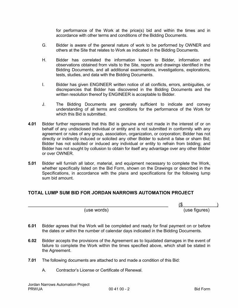
for performance of the Work at the price(s) bid and within the times and in accordance with other terms and conditions of the Bidding Documents.
G. Bidder is aware of the general nature of work to be performed by OWNER and
others at the Site that relates to Work as indicated in the Bidding Documents.
H. Bidder has correlated the information known to Bidder, information and observations obtained from visits to the Site, reports and drawings identified in the Bidding Documents, and all additional examinations, investigations, explorations, tests, studies, and data with the Bidding Documents.
I. Bidder has given ENGINEER written notice of all conflicts, errors, ambiguities, or
discrepancies that Bidder has discovered in the Bidding Documents and the written resolution thereof by ENGINEER is acceptable to Bidder.
J. The Bidding Documents are generally sufficient to indicate and convey
understanding of all terms and conditions for the performance of the Work for which this Bid is submitted.
4.01 Bidder further represents that this Bid is genuine and not made in the interest of or on behalf of any undisclosed individual or entity and is not submitted in conformity with any agreement or rules of any group, association, organization, or corporation; Bidder has not directly or indirectly induced or solicited any other Bidder to submit a false or sham Bid; Bidder has not solicited or induced any individual or entity to refrain from bidding; and Bidder has not sought by collusion to obtain for itself any advantage over any other Bidder or over OWNER.
5.01 Bidder will furnish all labor, material, and equipment necessary to complete the Work,
whether specifically listed on the Bid Form, shown on the Drawings or described in the Specifications, in accordance with the plans and specifications for the following lump sum bid amount.
TOTAL LUMP SUM BID FOR JORDAN NARROWS AUTOMATION PROJECT
($ ) (use words) (use figures) 6.01 Bidder agrees that the Work will be completed and ready for final payment on or before
the dates or within the number of calendar days indicated in the Bidding Documents. 6.02 Bidder accepts the provisions of the Agreement as to liquidated damages in the event of
failure to complete the Work within the times specified above, which shall be stated in the Agreement.
7.01 The following documents are attached to and made a condition of this Bid:
A. Contractor’s License or Certificate of Renewal.

Jordan Narrows Automation Project PRWUA 00 41 00 - 3 Bid Form
If Bidder is: An Individual Name (typed or printed): By: (Individual's Signature) Doing business as: Business address: Phone No.: Fax No.: A Partnership Partnership Name: By: (Signature of general partner) Name (typed or printed): Business address: Phone No.: Fax No.:

Jordan Narrows Automation Project PRWUA 00 41 00 - 4 Bid Form
A Corporation Corporation Name: State of Incorporation: Type (General Business, Professional, Service, Limited Liability): By: (Signature) Name (typed or printed): Title: Attest (Signature) Business address: Phone No.: Fax No.: Date of Qualification to do business is

Jordan Narrows Automation Project PRWUA 00 41 00 - 5 Bid Form
A Joint Venture Joint Venture Name: By: (Signature of joint venture partner) Name (typed or printed): Title: Business address: Phone No.: Fax No.: Joint Venture Name: By: (Signature of joint venture partner) Name (typed or printed): Title: Business address: Phone No.: Fax No.: (Each joint venture must sign. The manner of signing for each individual, partnership, and
corporation that is a party to the joint venture should be in the manner indicated above).
Jordan Narrows Automation Project PRWUA 26 05 00 - 1 Electrical General Conditions
SECTION 26 05 00
ELECTRICAL GENERAL CONDITIONS
PART 1 GENERAL
1.01 SUMMARY
A. Electrical construction shall consist of the following major components: 1. Installation of 1 new load center, and circuitry to electrically actuated
valves, automatic oiler, and other equipment as shown in the Contract Documents. See plans for details.
B. The General Conditions of these Specifications shall form a part and be included under this section of the Specifications. The Contractor shall provide all supervision, labor, material, equipment, machinery and any other items necessary to complete the electrical systems. All items of equipment are specified in the singular; however, the Contractor shall provide and install the number of items of equipment as indicated on the Drawings, and as required for complete systems.
1.02 WORK UNDER THIS DIVISION
A. It shall be noted that this Section of the Specifications includes: 1. A - GENERAL 2. B - ELECTRICAL REQUIREMENTS
1.03 CODES, RULES, PERMITS, FEES
A. The Contractor shall give all necessary notices, obtain all permits and pay all government and state sales taxes, fees, and other costs, including utility connections or extensions, in connection with his work; file all necessary plans, prepare all documents and obtain all necessary approvals of all governmental departments having jurisdiction; obtain all required certificates of inspection for his work and deliver same to the Engineer before request for acceptance and final payment of the work.
B. All materials furnished and all work installed shall comply with the current adopted Edition of the National Electrical Code, with the requirements of local utility companies, and with the requirements of all governmental departments having jurisdiction.
C. All material and equipment for the electrical portion of the system shall bear the approval label, or shall be listed by Underwriter's Laboratories, Incorporated or another Nationally Recognized Testing Laboratory (NRTL) approved by OSHA.
1.04 INTENT
A. It is the intention of these specifications and drawings to call for finished work, tested, and ready for operation. Wherever the word "provide" is used, it shall mean "furnish and install complete and ready for use."
Jordan Narrows Automation Project PRWUA 26 05 00 - 2 Electrical General Conditions
1.05 SURVEYS AND MEASUREMENTS
A. The Contractor shall base all measurements, both horizontal and vertical from established bench marks. All work shall agree with these established lines and levels. Verify all measurements at site and check correctness of same as related to the work.
B. Should the Contractor discover any discrepancy between actual measurements and those indicated, which prevents following good practice or the intent of the drawings and specifications, he shall notify the Engineer, through the General Contractor, and shall not proceed with his work until he has received instructions from the Engineer.
1.06 DRAWINGS
A. Drawings are diagrammatic and indicate the general arrangement of systems and work included in the contract. The engineering drawings and details shall be examined for exact locations of fixtures and equipment. Where they are not definitely located, this information shall be obtained from the Engineer.
B. The Contractor shall follow drawings in laying out work, and check drawings of other trades to verify spaces in which work will be installed.
1.07 "OR EQUAL"
A. Wherever the words “or equal" or “equal to” or “equivalent” are used in connection with any specified material, it is to be understood that such words mean any material or work of any kind claimed to be an equal in quality to the work or material specified, but does not require prior written approval by the Engineer.
B. Wherever the words "approved equal" are used in connection with any specified material, it is to be understood that such words mean any material or work of any kind claimed to be an equal in quality to the work or material specified and shall be so approved in writing by the Engineer.
C. It is further understood that no material or work shall be presented to the Engineer as work or material equal to that specified with the full understanding on the part of the manufacturers and agents for the so called "equal" material, and the full understanding on the part of the Contractor, that the Engineer is to use his own judgment in the matter, that his decision is final, and that in the event of an adverse condition, no claim of any sort shall be made against the Owner or Engineer.
1.08 SHOP DRAWINGS
A. The Contractor shall submit for approval, detailed shop drawings of all equipment and all material required to complete the project, and no material or equipment may be delivered to the job site or installed until the Contractor has in his possession the approved shop drawings for the particular material or equipment.
1.09 EQUIPMENT DEVIATIONS
A. Where the Contractor proposes to use an item of equipment other than that specified or detailed on the drawings, which requires any redesign of the

Jordan Narrows Automation Project PRWUA 26 05 00 - 3 Electrical General Conditions
structure, partitions, foundations, piping, wiring, or any other part of the mechanical, electrical, or structural layout, all such redesign and all new drawings and detailing required therefore shall be prepared by the Contractor at his own expense and approved by the Engineer.
B. Where such approved deviation requires a different quantity and arrangement of wiring, conduit, and equipment from that specified or indicated on the drawings, the Contractor shall furnish and install any such controllers, motors, starters, electrical wiring and conduit, and any other additional equipment required by the system at no additional cost to the Owner.
1.10 COOPERATION WITH OTHER TRADES
A. This Contractor shall give full cooperation to other trades and shall furnish in writing to the Contractor, with copies to the Engineer, any information necessary to permit the work of all trades to be installed satisfactorily and with the least possible interference or delay.
B. Where the work of the Contractor will be installed in close proximity to, or will interfere with work of other trades, he shall assist in working out space conditions to make a satisfactory adjustment. If the Contractor installs his work before coordinating with other trades or so as to cause any interference with work of other trades, he shall make the necessary changes in his work to correct the condition without extra charge.
C. The Contractor shall furnish to other trades, as required, all necessary shop details for the proper installation of work and for the purpose of coordinating adjacent work.
D. Refer to other Divisions of the Specifications for equipment furnished by others and work required thereof by the Contractor.
1.11 PROTECTION
A. The Contractor shall protect all work and material from damage by his work or workmen, and shall be liable for all damage thus caused.
B. The Contractor shall be responsible for work and equipment until finally inspected, tested, and accepted; he shall protect work against theft, injury or damage; and shall carefully store material and equipment received on site, which is not immediately installed. He shall close open ends of work with temporary covers or plugs during storage and construction to prevent entry of obstructing material.
1.12 SCAFFOLDING, RIGGING, HOISTING
A. The Contractor shall furnish all scaffolding, rigging, hoisting, and services necessary for erection and delivery into the premises of any electrical equipment and electrical apparatus furnished. Remove same from premises when no longer required.
1.13 MATERIAL AND WORKMANSHIP
A. All materials and apparatus required for the work, except as specifically specified otherwise, shall be new of first class quality, and shall be furnished, delivered,
Jordan Narrows Automation Project PRWUA 26 05 00 - 4 Electrical General Conditions
erected, connected, and finished in every detail, and shall be so selected and arranged as to fit properly into the available spaces. Where no specific kind or quality of material is given, a first class standard article as approved by the Engineer shall be furnished.
B. The Contractor shall furnish the services of an experienced superintendent who shall be constantly in charge of the installation or work, together with all skilled workmen, helpers, and labor required to unload, transfer, erect, connect up, adjust, start, operate, and test each system. The job superintendent shall be a Master Electrician licensed in the State that the work is being performed.
C. Unless otherwise specifically indicated on the plans or specifications, all equipment and materials shall be installed with the approval of the Engineer in accordance with the recommendations of the manufacturer. This includes the performance of such tests as the manufacturer recommends.
1.14 APPLICABLE STANDARDS
A. Provide work in accordance with applicable rules, codes, ordinances and regulations of local, state, federal governments, and other authorities having lawful jurisdiction. Conform to the latest editions and supplements of codes, standards, and recommended practices.
B. Drawings and specifications indicate minimum construction standards. Should any work indicated be substandard to any ordinances, lower codes, rules or regulations bearing on work, the Contractor shall promptly notify the Engineer in writing, through the General Contractor, of any necessary changes to be adjusted. However, if Contractor provides any work knowing it to be contrary to any ordinances, laws, rules and regulations, he shall thereby have assumed full responsibility and bear all costs involved for correction and compliance. In any instance where the specifications call for materials for construction of a better quality or larger size than required by codes, provisions of these specifications shall take precedence. Codes shall govern in case of direct conflict between codes, plans and specifications. 1. Safety Codes:
a. National Electrical Safety Code Handbook H30-National Bureau of Standards
b. Occupational Safety and Health Standard (OSHA) - Department of Labor
2. National Fire Codes:
a. NFPA NO. 70 - NATIONAL ELECTRIC CODE, current adopted Edition.
1.15 TESTS AND OPERATION RECORDS
A. General: Test all equipment installed under this specification and demonstrate its proper operation to the Engineer. No equipment shall be tested or operated for any other purpose, such as checking motor rotation, until it has been fully lubricated in accordance with manufacturer's instructions and, if it is a centrifugal pump, until it has been connected to piping systems and supplied with sufficient water so that it will not run dry.
Jordan Narrows Automation Project PRWUA 26 05 00 - 5 Electrical General Conditions
1. Any defects in workmanship, material, equipment or any grounds or short circuits shall be corrected by the Contractor before final acceptance.
2. Submit at least two (2) copies of data noted below to Engineer prior to final inspection.
3. Maintain a marked set of drawings to record all deviations made from routes, locations, circuiting, etc. shown on contract drawings. Prior to final inspection submit one new set of project drawings with deviations and changes clearly indicated.
4. AE2S will assist in the witness testing and startup of all equipment between the Owner and Contractor.
B. Testing: The entire electrical system shall be tested by Contractor in presence of the Engineer. Every local switch, panelboard, service breaker, safety switch, and circuit breaker shall be operated under load conditions.
1.16 DEMONSTRATION OF COMPLETED ELECTRICAL SYSTEMS
A. General: Upon completion of entire electrical systems, Contractor shall demonstrate to Engineer's satisfaction that all installed electrical systems are in perfect operating condition, that they perform all power and control functions intended and that they are installed in strict accordance with project drawings and specifications.
B. Materials: Contractor shall provide all necessary testing equipment, tools, materials, dummy loads, etc., required to properly demonstrate performance.
PART 2 ELECTRICAL REQUIREMENTS
2.01 BASIC MATERIALS
A. General: Material and equipment installed under this contract shall be new, unused, and without damage. Physical size of equivalent or substitute equipment shall not be larger than space provided including space required for access and maintenance of equipment.
PART 3 EXECUTION
NOT USED
END OF SECTION
Jordan Narrows Automation Project PRWUA 26 05 19 - 1 Low Voltage Electrical Power Conductors and Cables
SECTION 26 05 19
LOW VOLTAGE ELECTRICAL POWER CONDUCTORS AND CABLES
PART 1 GENERAL
1.01 SUMMARY
A. Section Includes: 1. Furnish and install all conductors to accomplish the circuiting, control and
power distribution as shown on the Drawings.
B. Related Work: 1. Section 260534 – Conduit
1.02 REFERENCE STANDARDS:
A. U.L. 486A - Wire connectors
B. NEMA WC5-1973
C. NEMA WC30-1976
D. NFPA 70 (National Electrical Code)
1.03 DELIVERY, STORAGE, AND HANDLING: A. Deliver conductors to project on standard coils or reels and suitably protected
from weather and damage during storage and handling.
PART 2 PRODUCTS
2.01 CONDUCTORS
A. Type 1 - 600V Rated General Purpose Single Conductor Cable 1. Construction:
a. No. 14 AWG and larger: Stranded Copper, (THHN/THWN-2). Solid Copper is acceptable for lighting and branch circuits.
b. All conductors shall contain factory color coded insulation in all standard colors to match the voltage level used.
c. Sequential footage markers shall be factory installed on the insulation jacket.
d. Provide Cable Tray (CT) rated cable where installed in cable tray.
e. Aluminum conductors not permitted. 2. Feeder Conductors:
a. 98 percent conductivity copper, 600 volt insulation. 3. Branch Circuit Conductors:
a. 98 percent conductivity copper, 600 volt insulation.
b. Conductors smaller than No. 14 AWG not permitted except in control panel.
4. Project Use Areas:
a. All general use indoor building circuiting. 5. Manufacturer:
Jordan Narrows Automation Project PRWUA 26 05 19 - 2 Low Voltage Electrical Power Conductors and Cables
a. Service Wire Co.
b. Okonite Co.
c. Southwire
d. Belden
e. Alpha Wire
F. Type 7 - Signal Cable - Single Pair 1. Construction
a. NFPA 70, Type CMP Single pair, twisted, 100% shield coverage, Class B, 16 AWG, stranded (19 x 29) tinned copper conductors (7 strand minimum).
b. 600V minimum insulation rating
c. 15 mil (nominal), 90 deg C PVC primary insulation with a flame retardant, low smoke PVC, plenum rated.
d. Conductors shall be shielded with a.35 x 5 mil (min.), 100% coverage, aluminum or copper mylar tape shield, or equal with an 18 gauge strand copper drain wire.
2. Ratings/Listings:
a. Flame Resistance: Comply with UL 1685 & NFPA 262
b. UL Temperature Rating: 75 deg C Dry, 90 deg C wet
c. ICEA S-73-532, S-61-402 3. Project Use Areas:
a. Any and all control circuiting requiring one shielded twisted pair from a control panel to a field instrument or similiar application.
4. Manufactuers:
a. Service Wire Co.
b. Okonite Co.
c. Southwire
d. Belden
e. Alpha Wire
PART 3 EXECUTION
3.01 INSTALLATION
A. Draw conductors into conduit only after conduit system is complete. Install in a manner so as not to injure insulation.
B. Use stranded, copper conductors only. Solid conductors are not acceptable.
C. Make splices on branch circuit conductors with solderless stapeless, mechanical wire connectors.
D. Tighten bolted, pressure type connectors to manufacturer's recommendations.
E. No. 10 AWG and smaller shall be stranded copper for all motor and control circuits. Branch circuits for lighting and convenience outlets shall be solid copper.
Jordan Narrows Automation Project PRWUA 26 05 19 - 3 Low Voltage Electrical Power Conductors and Cables
F. Make splices and terminations in control panel by using bolted, pressure type connections. Install according to manufacturer's recommendations. Owner to terminate all new control wires for the existing SCADA Control Panel.
G. Provide strain relief cord connectors and stainless steel mesh on all cords entering motor termination boxes, junction boxes or conduits.
H. Use factory color coded conductors with separate color for each phase and neutral conductor by integral pigmentation for all conductor sizes.
I. Use following codes:
CONDUCTOR SYSTEM VOLTAGE-120/240, THREE PHASE
Phase A Black Phase B Orange Phase C Blue Neutral White Equipment Ground Green
END OF SECTION
Jordan Narrows Automation Project PRWUA 26 05 34 - 1 Conduit
SECTION 26 05 34
CONDUIT
PART 1 GENERAL
1.01 SUMMARY
A. Section Includes: 1. Furnish and install a complete conduit system for all conductors. All
conduit shall be mounted off walls/ ceilings with galvanized unistrut.
B. Related Work: 1. Section 260519 - Low Voltage Electrical Power Conductors and Cables
1.02 REFERENCE STANDARDS:
A. U.L. 6 - Rigid metal conduit.
B. U.L. 360 - Liquid-tight flexible steel conduit.
C. U.L. 651 - Rigid non-metallic conduit.
D. NEMA Standard Publication TC-2 - Rigid PVC for underground installations.
E. NEMA Standard Publication RN 1-2005 – PVC coated rigid steel conduit.
1.03 DELIVERY, STORAGE AND HANDLING:
A. Store in a dry area, protected from the weather.
PART 2 PRODUCTS
2.01 RIGID ALUMINUM CONDUIT
A. Manufacturer: Equal to the Wheatland Steel Company
B. Type: 6063 aluminum ally, T-1 temeper, marine grade.
C. Manufactured in accordance with ANSI C80.5, UL 6A.
D. Install on Stainless steel strut stand offs such that it doesnt come in contact with concrete. When passing through a slab, ensure conduit is properly wrapped per conduit supplier recommendations.
E. Minimum trade size is 3/4"; other sizes as required by NEC based on quantity of conductors.
2.04 FLEXIBLE METAL CONDUIT (LIQUID-TIGHT)
A. Manufacturer: Equal to Alflex
B. Type: Steel
C. Weatherproof covering
2.05 METALLIC EXPANSION FITTINGS
A. Manufacturer: Equal to OZ Electrical Manufacturing Company.
Jordan Narrows Automation Project PRWUA 26 05 34 - 2 Conduit
B. Minimum trade size is 3/4-inch.
2.06 HANGERS AND SUPPORTS
A. Manufacturer: Equal to B-Line Products.
2.07 CONDUIT SEALS
A. Manufacturer: Equal to Appleton.
B. Type: Minimum trade size is 3/4-inch; other sizes as required for conduit sizes.
C. Provide listed sealoffs throughout Class I, Division 1, Group D or Class I, Division 2, Group D areas per NEC Articles 500 and 501.
PART 3 EXECUTION
3.01 INSTALLATION
A. Size conduits as shown on the Drawings or as required by National Electrical Code (whichever is larger) for number and size of conductors installed.
B. Minimum trade size for home runs is 3/4-inch.
C. Support all conduits from structural system, independent of ductwork, ceiling system supports and main runners. Do not support conduit from conduit.
D. Cut conduit joints square and ream smooth. Make bends with an approved bender, or utilize standard conduit elbows.
E. Building walls are mainly concrete or concrete block. Contractor shall core drill walls or coordinate reinforced, boxed out areas as required to install all conduit in a neat and workmanlike manner. Contractor shall also patch all wall penetrations and prepare surface for final paint by General Contractor. Coordinate routing of larger conduits (3” and larger) with other trades and with Field Engineer prior to installation.
F. Contractor shall provide sleeves or reinforced concrete boxed out openings through footings for all underground conduits. Coordinate with General Contractor.
G. Securely fasten conduit and raceways with malleable iron clamps (hot dipped galvanized, with clamp backs), or galvanized unistrut and hangers with suitable fastenings for all indoor dry applications. Utilize stainless steel unistrut and clamps for all exterior applications as well as damp or corrosive indoor applications such as below grade spaces and chemical rooms. The intent is to keep an air gap between conduit and finished wall surfaces to reduce the potential of moisture induced corrosion. All anchors shall be lead, expansion type with stainless steel hardware. Route all conduits parallel to and at right angles to building lines. Conduits mounted directly in contact with wall surface will not be acceptable.
H. Tie wires to hang or strap conduits not permitted.
I. Conduits shall be rigid aluminum unless noted otherwise.
Jordan Narrows Automation Project PRWUA 26 05 34 - 3 Conduit
3.02 RIGID ALUMINUM CONDUIT
A. Use rigid Aluminum conduit throughout entire project unless other types of conduit are specifically called for on Drawings or elsewhere in these specifications. Intent is to use Rigid Aluminum conduit everywhere except below finished grade or in floor slabs/ suspended ceilings. Fittings type to be threaded. Use threaded hubs (equal to Myers hub) where rigid conduit is connected to a thread less box or enclosure for indoor and outdoor applications. Lock nut with O-Ring is not an acceptable alternative.
END OF SECTION

Jordan Narrows Automation Project PRWUA 26 24 16 - 1 Panelboards
SECTION 26 24 16
PANELBOARDS
PART 1 GENERAL
1.01 SUMMARY
A. Section Includes: 1. Furnish and install circuit breaker type panelboards for branch circuit
distribution to lighting, general receptacle and small motor loads.
B. Related Work: 1. Section 260534 - Conduit 2. Section 260519 – Low Voltage Electrical Power Conductors and Cables 3. Section 260553 – Labeling for Electrical Systems 4. Section 264300 – Surge Protective Devices 5. Section 260914 – Electrical Power Monitoring
1.02 QUALITY ASSURANCE
A. NEMA PB-2
B. U.L. listed
1.03 SHOP DRAWINGS AND PRODUCT DATA
A. Clearly indicate (for each panelboard) amperage and phase of main bus, amperage of main circuit breaker, wire size and quantity of main lugs, grounding bar location, neutral bar location, quantity, arrangement and amperage of branch circuit breakers, quantity of spaces, physical dimension of enclosure, weight, directory card location and type, type of lock, flush or surface cover, short circuit withstand rating in R.M.S. amperes.
1.04 DELIVERY, STORAGE AND HANDLING
A. Box, crate, or otherwise completely enclose and protect all equipment during shipment, handling, and storage.
B. Protect equipment from exposure to elements and keep all items thoroughly dry at all times.
C. Store in a dry area, protected from the weather.
D. Painted Surfaces: Protect against impact, abrasion, discoloration, and other damage.
PART 2 PRODUCTS
2.01 LIGHTING AND APPLIANCE PANELS (120/208V OR 120/240V)
A. Utilize lighting and appliance panels (denoted by L prefix) for 120/208 volt, 3 phase operation or 120/240V for single phase operation as indicated on the Drawings. Install bolt-on, thermal magnetic circuit breakers with a minimum interrupting rating of 22,000 amperes R.M.S. unless noted otherwise on Drawings.
Jordan Narrows Automation Project PRWUA 26 24 16 - 2 Panelboards
B. Circuit breakers shall have a trip indication different from the "off" or "on" position.
C. Install in a NEMA 1 surface mount enclosure, unless indicated otherwise on the Drawings. Provide a hinged front breaker access door and a separate hinged front cover (two separate hinges) for personnel/contractor access without completely removing front panelboard cover.
D. Install common trip multipole circuit breakers. Handle ties are not permitted.
E. Full cabinet height bussing includes active, spare and blank breaker locations with sizes, branches, mounting, main circuit breakers, etc., as shown in Schedule on the Drawings.
F. Provide adequate wiring space according to the National Electric Code.
G. Provide panels with a flush, hinged door with lock. Key locks alike.
H. Isolated neutral bar and ground bar in all panelboards. Provide 200% rated neutrals where indicated on the Drawings.
I. Provide distributed phase bussing.
J. Metal framed circuit directory and card with plastic covering located on the inside.
K. Tin plated copper or silver plated aluminum bussing, TVSS protection and additional requirements as noted on Panelboard Schedule on Drawings.
2.03 MANUFACTURERS
A. Lighting and Appliance Panels (L Prefix): 1. Square D Type NQOD 2. General Electric equal 3. Siemens equal 4. Cutler Hammer equal 2.04 CABLE TIES
A. Equal to Thomas and Betts "TY-RAP"
PART 3 EXECUTION
3.01 INSTALLATION
A. Install all panelboards plumb with top at 72” above the finished floor.
B. Type circuit directory with spare positions left blank. Hand lettering not acceptable.
C. Carefully clean panelboard to remove all wire scraps, dirt and dust.
D. Neatly dress conductors and bundle with nylon cable ties.
E. Tighten all lugs and bolts to manufacturer's recommendations.
F. Use touch up paint, as recommended by the manufacturer, to repair scratches and other surface defects.
END OF SECTION

APPENDIX A
AGREEMENT
BETWEEN PROVO RIVER WATER USERS ASSOCIATION
AND
_________________________________________
FOR JORDAN NARROWS PUMPING PLANT AUTOMATION PROJECT
(electrical component)
This Agreement is made as of the ____ day of February, 2017, by and between Provo River Water Users Association, a Utah nonprofit corporation (“OWNER”) and ___________________________________________________________a Utah ___________________ (“CONTRACTOR”).
AGREEMENT PURPOSES
OWNER owns, operates and maintains the Jordan Narrows Pumping Plant on the Jordan River in the area commonly called the Jordan Narrows, near the Utah County, Salt Lake County line. Owner is automating its controls for the Jordan Narrows Pumping Plant. OWNER requested quotes for the electrical component of the Jordan Narrows Pumping Plant Automation Project. That request for quotes is attached to this Agreement as Exhibit A and is made a part of this Agreement as if restated here. CONTRACTOR submitted its quote to OWNER, which is attached to this Agreement as Exhibit B and is made a part of this Agreement as if restated here. OWNER has selected CONTRACTOR to perform the WORK pursuant to the terms and conditions of this Agreement.
AGREEMENT TERMS
OWNER and CONTRACTOR, in consideration of the mutual covenants described in this Agreement, agree as follows:
ARTICLE 1 WORK 1.1 The WORK. The WORK is furnishing all labor, supervision, services, materials, equipment, and supplies, and doing everything as described in this Agreement, including providing the good and services described in Exhibits A and B. 1.2 Compliance. The WORK shall in all respects be performed in compliance with all applicable federal, state and local statutes, rules, regulations, ordinances, codes and common law. The WORK shall be performed in a safe, professional, workmanlike manner and in all respects in compliance with generally accepted industry standards and codes.
ARTICLE 2 CONTRACT TIME 2.1 Completion Date. The WORK shall be substantially complete, within ____days
from the date of the Notice to Proceed. 2.2 Liquidated Damages. OWNER and CONTRACTOR recognize that time is of the
essence of this Agreement and that the OWNER will suffer financial loss if the WORK is not completed within the time specified in paragraph 2.1 above or any extension granted by OWNER. They also recognize the delays, expense and difficulties involved in proving the actual loss suffered by OWNER if the WORK is not completed on time. Accordingly, instead of requiring any proof of loss, OWNER and CONTRACTOR agree that as liquidated damages for delay (but not as a penalty) CONTRACTOR shall pay OWNER $ ___________for each day that expires after the time specified in paragraph 2.1 until the WORK is substantially complete. If, after Substantial Completion, CONTRACTOR neglects, refuses or fails to complete the remaining WORK within 30 days or any extension granted by OWNER, CONTRACTOR shall pay OWNER $______for each day that expires after the 30 days until the WORK is complete and ready for final payment.
ARTICLE 3 CONTRACT PRICE OWNER shall pay CONTRACTOR for completion of the WORK in accordance with this Agreement, at the prices stated in Exhibit B, not to exceed $____________. ARTICLE 4 PAYMENT PROCEDURES 4.1 Progress Payments: OWNER shall make progress payments on the basis of
CONTRACTOR'S proper invoices, on or about the ____ day of each month during the WORK. All amounts not paid when due shall bear interest at the rate of 6% per annum.
4.2 Final Payment: Upon final completion and acceptance of the WORK, OWNER
shall pay the remainder of the CONTRACT PRICE. 4.3 Retainage: The OWNER shall retain 5% of the balance due to the
CONTRACTOR in an interest bearing account. Upon final completion to the reasonable satisfaction of the OWNER, the retainage, with interest, shall be paid to the CONTRACTOR.
ARTICLE 5 CONTRACTOR'S REPRESENTATION In order to induce OWNER to enter into this Agreement, CONTRACTOR makes the following representations: 5.1 CONTRACTOR has familiarized itself with the nature and extent of the WORK,
site, locality, and all local conditions, laws, regulations, ordinances and codes that in any manner may affect cost, progress, performance or furnishing of the WORK.
5.2 CONTRACTOR has made all such examinations, investigations, explorations,
tests, reports and studies which pertain to the conditions at or contiguous to the site or otherwise may affect the cost, progress, performance or furnishing of the WORK in accordance with the terms and conditions of this Agreement. No additional examinations, investigations, explorations, tests, reports, studies or similar information or data are or will be required by CONTRACTOR for such purposes.
5.3 CONTRACTOR has given OWNER written notice of all conflicts, errors or
discrepancies that he has discovered in Exhibits A and B to the Agreement. This Agreement, including Exhibits A and B, are sufficient to indicate and convey understanding of all terms and conditions for performance and furnishing of the WORK.
ARTICLE 6
INSURANCE
6.1 CONTRACTOR and all of CONTRACTOR’S subcontractors shall maintain, at no cost to the OWNER, the insurance and bonds as described in this Article 6, and provide evidence of compliance satisfactory to OWNER as described in this Article 6.
6.2 MINIMUM LIMITS OF INSURANCE. Except as approved in writing by OWNER
in advance, CONTRACTOR and all of CONTRACTOR’S contractors shall maintain limits no less than:
BROAD FORM COMMERCIAL GENERAL LIABILITY (including claims arising from: premises-operations, independent contractors, products-completed operations, personal and advertising injury, and liability assumed under an insured contract.):
i. Combined Single Limit (Bodily Injury and Property Damage):
1. $2,000,000 Per Occurrence ii. Personal Injury (including completed operations and products liability):
1. $2,000,000 Each Occurrence iii. General Aggregate:
1. $3,000,000 iv. Products - Comp/OP Aggregate:
1. $3,000,000 v. Limits to apply to this project individually.
AUTOMOBILE LIABILITY:
vi. $2,000,000 Per Occurrence vii. "Any Auto" coverage required.
WORKERS' COMPENSATION and EMPOLOYERS LIABILITY:
viii. Workers' compensation statutory limits. ix. Employers Liability statutory limits.
CONTRACTORS POLLUTION LIABILITY:
x. $1,000,000 Per Claim xi. $1,000,000 Aggregate xii. Coverage applies to this project individually.
6.3 DEDUCTIBLES AND SELF-INSURED RETENTIONS. Any deductibles or self-
insured retentions (SIRs) must be declared to and approved by the OWNER in writing. At the option of the OWNER, either; the insurer may be required to reduce or eliminate such deductibles or SIRs as respects the OWNER, its directors, officers, and employees as additional insureds; or the CONTRACTOR may be required to procure a bond or other instrument guaranteeing payment of losses and related investigations, claim distribution, and defense expenses of the OWNER, its directors, officers, and employees as additional insureds. The OWNER does not ordinarily approve deductibles in an amount exceeding 2.5% of the required minimum limits described above or $50,000, whichever is less. The OWNER does not ordinarily approve SIRs in an amount exceeding 1.0% of the required minimum limits described above or $20,000, whichever is less. With respect to any deductible or SIR, the CONTRACTOR shall pay for costs related to losses, investigations, claim distribution, and defense expenses of the OWNER, its directors, officers, and employees as additional insureds that would otherwise be covered by an insurer under the coverages described in these insurance requirements if no deductible or SIR existed.
6.4 OTHER INSURANCE PROVISIONS. OWNER, its directors, officers, and
employees are to be covered as additional insureds under the Commercial General Liability policy for claims arising out of the WORK. Additional insured coverage shall be primary to any other coverage available to OWNER or its directors, officers, and employees. CONTRACTOR shall provide OWNER a subrogation waiver from CONTRACTOR’S Worker’s Compensation insurer.
6.5 ACCEPTABILITY OF INSURERS. Insurance and bonds are to be placed with insurers admitted in the State of Utah with a Bests' rating of no less than A-, IX, and in the limits as listed in this document, unless approved in writing by the OWNER.
6.6 VERIFICATION OF COVERAGE. CONTRACTOR and all of CONTRACTOR’S
contractors shall furnish OWNER with certificates of insurance and with original endorsements effecting coverage required by this clause. The certificates and endorsements are to be signed by a person authorized by that insurer to bind coverage on its behalf. The certificates and endorsements are to be provided on forms acceptable to the OWNER before work commences. OWNER reserves the right to require complete, certified copies of all required insurance policies, with all endorsements, at any time. CONTRACTOR shall provide an insurance certificate and an endorsement evidencing compliance with this provision at least annually. From time to time OWNER may increase the requirement for a liability limit by providing reasonable written notice to CONTRACTOR of such a change.
6.7 PERFORMANCE AND PAYMENT BONDS. CONTRACTOR and all of
CONTRACTOR’S subcontractors shall furnish OWNER with performance and payment bonds for the full sum of their contracts, naming the OWNER as oblige, in the OWNER’S standard form, attached as Exhibit C.
ARTICLE 7
DEFENSE AND INDEMNITY
CONTRACTOR shall defend, indemnify and hold OWNER and its officers, directors and employees harmless, including costs and attorneys’ fees, from any claim, demand, action or cause of action: (i) alleging that OWNER was at fault in hiring CONTRACTOR; or (ii) alleging that OWNER was at fault in failing to supervise, inspect, direct, instruct, warn or otherwise manage or control CONTRACTOR; or (iii) alleging that OWNER knew of, should have known of, or had constructive knowledge of a dangerous condition created by CONTRACTOR or any employee, agent or contractor of CONTRACTOR; or (iv) alleging OWNER is vicariously liable for acts or omissions of CONTRACTOR or any employee, agent or contractor of CONTRACTOR (under the Peculiar Risk Doctrine or otherwise). This defense and indemnity obligation is not intended to hold OWNER or its officers, directors, or employees harmless from any claim that is not derivative of CONTRACTOR’S actions or omissions as described. In no event shall any fault of CONTRACTOR or CONTRACTOR’S employees or contractors be reapportioned to OWNER, its officers, directors or employees. CONTRACTOR shall indemnify and hold OWNER and its officers, directors and employees harmless from any such reapportionment of fault. The described duty to defend and indemnify described above is not intended to run to the benefit of any OWNER liability insurer to the extent such insurer would be responsible for defense costs or indemnity beyond OWNER’S deductible or self-insured retention.
ARTICLE 8 REMEDIES
The parties will first submit any claim or dispute to the authorized representative of the other party. If the matter is not resolved satisfactorily, the parties may submit the dispute or claim in concise written form with any supporting documentation to the General Manager (or the equivalent) of the other party. If the matter is not resolved satisfactorily the dispute or claim will be submitted to non-binding mediation, with a qualified mediator selected by the parties, with each party sharing the cost of that non-binding mediation. After and only if these processes are first followed and the dispute or claim remains unresolved, an action may be brought in the Third Judicial District Court of the State of Utah In and For Salt Lake County. The prevailing party shall be awarded reasonable costs, including engineering, witness and attorneys’ costs and fees. Under no circumstances shall OWNER or its officers, directors or employees be liable for any consequential damages. ARTICLE 9
NOTICE
Any notice to be given hereunder shall be deemed given when sent by registered or certified mail, postage prepaid to the parties at their respective addresses stated below or at any other address when notice of such change of address has been given as provided in this Article. To Owner: Jeffrey D. Budge, P.E. Operations & Engineering Manager Provo River Water Users Association 285 West 1100 North Pleasant Grove, UT 84062 To Contractor: [Insert Contractor Contact Information]
ARTICLE 10
MISCELLANEOUS 10.1 No Assignment. No assignment by a party of any rights under or interests in this
Agreement will be binding on another party hereto without the written consent of the party sought to be bound.
10.2 Entire Agreement. This Agreement constitutes the entire agreement between
the parties and supersedes any prior negotiations or discussion regarding the WORK, and cannot be altered except through a written instrument signed by all parties.
CONTRACTOR: UTAH LICENSE # By: Its:
OWNER: PROVO RIVER WATER USERS ASSOCIATION Mike Wilson, President
4834-9248-5185.1 16001.22