RE Family Implementation Method and Sample Code for ...
76
Application Note R01AN5645EJ0101 Rev.1.01 Page 1 of 74 Nov.30.21 RE Family Implementation Method and Sample Code for Firmware Updates on the RE Family Using a UART Introduction This application note describes the implementation of firmware updates using RE Family MCUs. Renesas has implemented firmware update functionality based on a common design policy for all MCU families that takes into consideration the possibility of momentary power interruptions. For details of the common design policy for Renesas MCUs, refer to Renesas MCU Firmware Update Design Policy (R01AN5548). Target Devices RE01-1500KB Group RE01-256KB Group Related Documents • Renesas MCU Firmware Update Design Policy (R01AN5548) • RE01 Group Products with 1.5-Mbyte Flash Memory User’s Manual: Hardware (R01UH0796) • RE01 Group Products with 256-KB Flash Memory User’s Manual: Hardware (R01UH0894)
Transcript of RE Family Implementation Method and Sample Code for ...

Application Note
R01AN5645EJ0101 Rev.1.01 Page 1 of 74 Nov.30.21
RE Family Implementation Method and Sample Code for Firmware Updates on the RE Family Using a UART Introduction This application note describes the implementation of firmware updates using RE Family MCUs. Renesas has implemented firmware update functionality based on a common design policy for all MCU families that takes into consideration the possibility of momentary power interruptions. For details of the common design policy for Renesas MCUs, refer to Renesas MCU Firmware Update Design Policy (R01AN5548).
Target Devices RE01-1500KB Group
RE01-256KB Group
Related Documents • Renesas MCU Firmware Update Design Policy (R01AN5548) • RE01 Group Products with 1.5-Mbyte Flash Memory User’s Manual: Hardware (R01UH0796) • RE01 Group Products with 256-KB Flash Memory User’s Manual: Hardware (R01UH0894)

RE Family Implementation Method and Sample Code for Firmware Updates on the RE Family Using a UART
R01AN5645EJ0101 Rev.1.01 Page 2 of 74 Nov.30.21
Contents
1. Overview .................................................................................................................................... 4 1.1 Limitations ............................................................................................................................................... 4 1.2 List of Terms ............................................................................................................................................ 4 1.3 Product Structure .................................................................................................................................... 5 1.4 Development Environment ...................................................................................................................... 6 1.5 ROM and RAM Size Requirements......................................................................................................... 7 1.6 Stack Size Requirements ........................................................................................................................ 7 1.7 Sections ................................................................................................................................................... 7
2. System Configuration ................................................................................................................ 8 2.1 Using the RE01-1500KB Evaluation Kit ................................................................................................ 11 2.2 Using the RE01-256KB Evaluation Kit .................................................................................................. 11
3. Description of Functions .......................................................................................................... 12 3.1 Hardware Functions .............................................................................................................................. 12 3.1.1 Background Operation (BGO) ............................................................................................................. 12 3.1.2 Memory Protection .............................................................................................................................. 12 3.1.3 Power Supply Modes and Power Control Modes ............................................................................... 13 3.2 Software Functions ................................................................................................................................ 13 3.2.1 RE Software Development Kit ............................................................................................................. 13 3.2.2 Bootloader ........................................................................................................................................... 13
4. Data Format ............................................................................................................................. 14 4.1 Memory Map .......................................................................................................................................... 14 4.2 Signature Verification ............................................................................................................................ 15 4.2.1 Generate ECC key pair ....................................................................................................................... 15 4.2.2 Changes to the Bootloader and User Program Projects ..................................................................... 15 4.2.2.1 Configuration Changes ...................................................................................................................... 15 4.2.2.2 Setting the public key ........................................................................................................................ 16 4.2.3 .Mot File Conversion Tool ................................................................................................................... 17 4.2.3.1 Initial Firm Tab ................................................................................................................................... 17 4.2.3.2 Update Firm Tab ............................................................................................................................... 18 4.3 .Mot File Conversion Tool ..................................................................................................................... 19 4.3.1.1 session key Tab ................................................................................................................................ 19 4.3.1.2 Key Wrap Tab ................................................................................................................................... 20 4.3.1.3 Initial Firm Tab ................................................................................................................................... 21 4.3.1.4 Update Firm Tab ............................................................................................................................... 23
5. Operation of Sample Program ................................................................................................. 24 5.1 Preparation ............................................................................................................................................ 25 5.2 Sample Software Operation Instructions ............................................................................................... 26

RE Family Implementation Method and Sample Code for Firmware Updates on the RE Family Using a UART
R01AN5645EJ0101 Rev.1.01 Page 3 of 74 Nov.30.21
5.2.1 Creating a Motorola File Containing the Bootloader and User Programs ........................................... 26 5.2.2 Creating a Motorola File Containing the Bootloader and User Program V.1.00 ................................. 29 5.2.3 Creating a Firmware Update File (.rsu File) ........................................................................................ 31 5.2.4 Downloading and Running the Bootloader and User Program V.1.00 ............................................... 33 5.2.5 Downloading the User Program Update ............................................................................................. 39 5.3 Switching the RE01-1500KB Sample Software from Not Using BGO to Using BGO ........................... 42
6. API Information ........................................................................................................................ 45
7. API Functions .......................................................................................................................... 47 7.1.1 R_FWUP_SecureBoot ........................................................................................................................ 48 7.1.2 R_FWUP_ExecuteFirmware ............................................................................................................... 49 7.2.1 R_FWUP_Open .................................................................................................................................. 50 7.2.2 R_FWUP_Close .................................................................................................................................. 51 7.2.3 R_FWUP_Operation ........................................................................................................................... 52 7.2.4 R_FWUP_SetEndOfLife ...................................................................................................................... 53 7.2.5 R_FWUP_SoftwareReset .................................................................................................................... 54 7.3.1 R_FWUP_CreateFileForRx ................................................................................................................. 55 7.3.2 R_FWUP_Abort ................................................................................................................................... 56 7.3.3 R_FWUP_WriteBlock .......................................................................................................................... 57 7.3.4 R_FWUP_CloseFile ............................................................................................................................ 58 7.3.5 R_FWUP_CheckFileSignature ............................................................................................................ 59 7.3.6 R_FWUP_ReadAndAssumeCertificate ............................................................................................... 60 7.3.7 R_FWUP_ResetDevice ....................................................................................................................... 61 7.3.8 R_FWUP_ActivateNewImage ............................................................................................................. 62 7.3.9 R_FWUP_SetPlatformImageState ...................................................................................................... 63 7.3.10 R_FWUP_GetPlatformImageState ..................................................................................................... 64 7.3.11 R_FWUP_GetVersion ......................................................................................................................... 65
8. Firmware Update Operation Details ........................................................................................ 66 8.1 Processing Sequence at Bootloader Startup ........................................................................................ 66 8.2 Firmware Update Processing Flowchart ............................................................................................... 73
Revision History .............................................................................................................................. 74

RE Family Implementation Method and Sample Code for Firmware Updates on the RE Family Using a UART
R01AN5645EJ0101 Rev.1.01 Page 4 of 74 Nov.30.21
1. Overview 1.1 Limitations The startup mode must be normal startup mode in order to use the firmware update functionality. When using the firmware update functionality, make sure to select all-power supply mode (ALLPWON) as the power supply mode. In the other power supply modes the flash memory is not accessible, so the firmware update functionality will not work. For details of the startup modes and power supply modes, refer to the User’s Manual Hardware of the RE Family MCU.
1.2 List of Terms Explanations of terms and the full forms of abbreviations used in this document are listed below.
Bootloader When a user program is installed, this program verifies the user program before it is allowed to run on the device. It is a different program from the boot firmware that runs when SCI/USB boot mode is selected as the startup mode.
Initial firmware The initial user program programmed on the device when it is shipped from the factory.
Bootloader, bootloader area A program that verifies that the user application program has not been modified, and the area in which the program is located.
User program area, exe area The area from which the user application program is run. Software for user system operation and firmware update operation is stored in this area.
Temporary area, tmp area A temporary area for programming. It is the same size as the exe area and used to store the new firmware temporarily when performing a firmware update.
Download data format area An information area containing data such as state and verification information for the user application program to be updated. For details, refer to 7.1, Download Data Format, in Renesas MCU Firmware Update Design Policy (R01AN5548).
FAW Abbreviation of “flash access window.” This is a user area in the code flash memory, and the portion not set as the FAW is in the command lock state.
FSPR The access window protection bit. A bit in the FAW register used to control the FAW functionality.

RE Family Implementation Method and Sample Code for Firmware Updates on the RE Family Using a UART
R01AN5645EJ0101 Rev.1.01 Page 5 of 74 Nov.30.21
1.3 Product Structure The product contains the files listed below.
File/Directory (Bold) Name Description R01AN5645EJ0101.pdf This document (English) R01AN5645JJ0101.pdf Application note (Japanese) RE01_CMSIS_1_0_1_fwup Module folder RE01_1500KB_DFP Package folder (1500KB) Device Firmware updater driver RE01_256KB_DFP Package folder (256KB) Device Firmware updater driver Demos Demo project folder re01_1500kb_ek_fwup_sample.zip Sample code for RE01-1500KB re01_1500kb_ek_fwup_boot_loader *1 Bootloader project:
The project for the bootloader programmed on the device when it is shipped from the factory.
re01_1500kb_ek_fwup_user_program_V100 *1
User program project: The user program following a firmware update. The project for the user program programmed on the device when it is shipped from the factory.
re01_1500kb_ek_fwup_user_program_V101 *1
User program project: The project for the user program programmed on the device in the field.
re01_256kb_ek_fwup_sample.zip Sample code for RE01-256KB re01_256kb_ek_fwup_boot_loader *1 Bootloader project:
The project for the bootloader programmed on the device when it is shipped from the factory.
re01_256kb_ek_fwup_user_program_V100 *1
User program project: The user program following a firmware update. The project for the user program programmed on the device when it is shipped from the factory.
re01_256kb_ek_fwup_user_program_V101 *1
User program project: The project for the user program programmed on the device in the field.
Tools renesas_secure_flash_programmer.zip *2 Tool for appending the download data format to a
user program to perform a firmware update or to create a Motorola S format file combining the bootloader and initial firmware.
Notes: 1. This application note uses the following open source. TinyCrypt https://01.org/tinycrypt Version : 0.2.8
License : https://github.com/intel/tinycrypt/blob/master/LICENSE TinyCrypt exists in the following folders of each project. \src\tinycrypt
2. This application note uses the following open source. Bouncy Castle https://bouncycastle.org/ Version : 1.8.5
License : https://bouncycastle.org/licence.html The DLL in the following folder is Bouncy Castle. mot-file-converter\Renesas Secure Flash Programmer\bin\Debug\BouncyCastle.Crypto.dll

RE Family Implementation Method and Sample Code for Firmware Updates on the RE Family Using a UART
R01AN5645EJ0101 Rev.1.01 Page 6 of 74 Nov.30.21
1.4 Development Environment The sample program was developed on the development environment shown below. When developing user applications, use the versions listed below or newer.
Table 1.1 Operation Confirmation Environment (1)
Item Description Integrated development environment
Renesas Electronics Corporation e2studio Version 2021-10
C compiler GCC ARM Embedded Version 6.3.1.20170620 GNU 6-2017-q2-update Compile options: The following changes were made to the default settings of the integrated development environment. Linker file settings: • Secure boot project
$PROJ_DIR$\script\RE01_1500KB_SecureBoot.ld • User program project
$PROJ_DIR$\script\RE01_1500KB_UserProgram.ld Emulator/debugger Segger JLink OB MCU R7F0E015D2CFB 144-pin Board Renesas Electronics Corporation Evaluation Board RE01-1500KB
Product number: RTK70E015DSxxxxxBE For details of board settings, refer to section 2, System Configuration.
RE01-1500KB CMSIS Driver Package
Ver.1.20
Table 1.2 Operation Confirmation Environment (2)
Item Description Integrated development environment
Renesas Electronics Corporation e2studio Version 2021-10
C compiler GCC ARM Embedded Version 6.3.1.20170620 GNU 6-2017-q2-update Compile options: The following changes were made to the default settings of the integrated development environment. Linker file settings: • Secure boot project
$PROJ_DIR$\script\RE01_256KB_SecureBoot.ld • User program project
$PROJ_DIR$\script\RE01_256KB_UserProgram.ld Emulator/debugger Segger JLink MCU R7F0E01182CFP 100-pin Board Renesas Electronics Corporation Evaluation Kit RE01-256KB
Product number: RTK70E0118SxxxxxBJ RE01-256KB CMSIS Driver Package
Ver.1.00

RE Family Implementation Method and Sample Code for Firmware Updates on the RE Family Using a UART
R01AN5645EJ0101 Rev.1.01 Page 7 of 74 Nov.30.21
1.5 ROM and RAM Size Requirements The ROM (code) and RAM size requirements of the firmware updater driver are listed below. These requirements are the same for the RE01-1500KB and RE01-256KB.
Measured using -O2 as the GCC optimization setting.
Table 1.3 ROM and RAM Size Requirements
Compiler ROM (KB)*1 RAM (KB) Code Data Code Data
Bootloader 0.1 2 3.8 8 User program 1 0.1 2.1 0.1
Note: 1. The ROM sizes shown are the values that apply when all functions are enabled in the configuration file.
1.6 Stack Size Requirements The stack size requirements are listed below. These requirements are the same for the RE01-1500KB and RE01-256KB.
Bootloader: 232 bytes
User program: 4,128 bytes
1.7 Sections The sections allocated in the code are listed below.
Table 1.4 Bootloader Project Section (RE01-1500KB)
Address Range Area Section Name 0000 0000h to 0000 FFFFh Bootloader area No section specified*1
Note: 1. All code for which no section is specified in the linker file is allocated to the secure boot area. Table 1.5 User Program Project Section (RE01-1500KB)
Address Area Section Name 0001 0300h to 000C 7FFFh User program area No section specified*1
Note: 1. All code for which no section is specified in the linker file is allocated to the user program area. Table 1.6 Bootloader Project Section (RE01-256KB)
Address Area Section Name 0000 0000h to 0000 FFFFh Bootloader area No section specified*1
Note: 1. All code for which no section is specified in the linker file is allocated to the secure boot area. Table 1.7 User Program Project Section (RE01-256KB)
Address Area Section Name 0001 0300h to 0003 FFFFh User program area No section specified*1
Note: 1. All code for which no section is specified in the linker file is allocated to the user program area.

RE Family Implementation Method and Sample Code for Firmware Updates on the RE Family Using a UART
R01AN5645EJ0101 Rev.1.01 Page 8 of 74 Nov.30.21
2. System Configuration This application note describes sample programs that can be used to confirm the following two operations.
• Programming of firmware before shipment from the factory • Updating of firmware in the field following shipment from the factory When updating the firmware in the field, Tera Term is used to send the firmware update from the PC to the RE01 Evaluation Kit via a USB link. The data passes through the USB-serial converter chip on the RE01 Evaluation Kit board and then is transferred via the UART to the RE01 MCU. The RE01 MCU then applies the received firmware update.
User program V.1.01
USB cable
User program V.1.00
Motorola file
Motorola convert tool
User program V.1.00
Bootloader
RE01 flash memory program
[1]
[1]
[2]
[1]
User program area
Bootloader area
Tempraryarea
JFlashLite
Bootloader Motorola file
SWDUSB-serial
UART
User program V.1.01
Motorola file
[2]
User program V.1.00
Boot Loader
User program V.1.01
User program V.1.00
Boot Loader
User program V.1.01
Boot Loader
User program V.1.01
User program V.1.01
From UART
Copy
Initial firmware programmed at the factory.
New firmware updated in the field.
[2]
[2][2]
[1]
Figure 2.1 System Configuration: Overall View

RE Family Implementation Method and Sample Code for Firmware Updates on the RE Family Using a UART
R01AN5645EJ0101 Rev.1.01 Page 9 of 74 Nov.30.21
0018 0000h
0010 0000h
0008 0000h
0000 0000h
2000 0000h
2004 0000h
0008 0300h
0010 0300h
Temporary area
User programarea
000C 8000h
0001 0000h
0000 0000h
Bootloaderarea
SRAM
User program download data
format area
0001 0300h
000C 8300h
Temporary download data
format area
Without BGO With BGO
Figure 2.2 RE01-1500KB Memory Map

RE Family Implementation Method and Sample Code for Firmware Updates on the RE Family Using a UART
R01AN5645EJ0101 Rev.1.01 Page 10 of 74 Nov.30.21
0018 0000h
0000 0000h
2000 0000h
2004 0000h
Temporary area
User programarea
0002 8000h
0001 0000h
Bootloaderarea
SRAM
User program download data
format area
0001 0300h
0002 8300h
Temporary download data
format area
Without BGO
Figure 2.3 RE01-256KB Memory Map

RE Family Implementation Method and Sample Code for Firmware Updates on the RE Family Using a UART
R01AN5645EJ0101 Rev.1.01 Page 11 of 74 Nov.30.21
2.1 Using the RE01-1500KB Evaluation Kit The method of connecting the RE01-1500KB Evaluation Kit board (EK board) to the PC is described below.
Either connect the PC to the JLink OB on the EK board using a USB cable, or use a USB cable to connect to the USB to serial adapter used to transfer updates to the user program. Refer to Figure 2.4.
Figure 2.4 Wired Connections between PC, JLink OB, and RE01-1500KB Evaluation Kit
2.2 Using the RE01-256KB Evaluation Kit The method of connecting the RE01-256KB EK board to the PC is described below.
Either connect the PC to the JLink OB on the EK board using a USB cable, or use a USB cable to connect to the USB to serial adapter used to transfer updates to the user program. Refer to Figure 2.5.
Figure 2.5 PC Wired Connections between PC, JLink OB, and RE01-256KB Evaluation Kit
USB (JLink OB)
USB serial (USART)
USB (JLink OB)
USB serial (USART)

RE Family Implementation Method and Sample Code for Firmware Updates on the RE Family Using a UART
R01AN5645EJ0101 Rev.1.01 Page 12 of 74 Nov.30.21
3. Description of Functions The on-chip functions of the device and the software used to implement firmware update functionality on RE Family MCUs are described in this chapter.
3.1 Hardware Functions The hardware functions used by the firmware update functionality are described below. For details of each of these functions, refer to the User’s Manual Hardware of the MCU.
3.1.1 Background Operation (BGO) On an MCU with on-chip flash memory, to program the flash memory it is necessary first to copy to the RAM the program that will perform the programming of the application software, and then to execute the appropriate flash memory programming commands from the RAM. This makes it extremely difficult to program the flash memory while maintaining system operation.
On the RE01-1500KB the flash memory is provided with a background operation (BGO) function that removes the necessity of running the program from the RAM so long as the area of the flash memory to be programmed and the execution (exe) area are different. This makes it very simple to maintain system operation while programming the flash memory.
3.1.2 Memory Protection In order to be able to verify the user program when it is run, the bootloader should be stored in non-volatile memory and it should not be possible to overwrite it. The MCU has a flash access window (FAW) function that can be used to prohibit overwriting of the FAW and of the register used to make FAW settings by setting the FSPR bit. This prohibits overwriting of the bootloader area.
Caution
Once this setting has been made, it is no longer possible to return the MCU to the blank chip state.

RE Family Implementation Method and Sample Code for Firmware Updates on the RE Family Using a UART
R01AN5645EJ0101 Rev.1.01 Page 13 of 74 Nov.30.21
3.1.3 Power Supply Modes and Power Control Modes It is necessary to set the correct power supply mode and power control mode when using the firmware update functionality. There are three power supply modes: all-power supply mode (ALLPWON), flash-excluded power supply mode (EXFPWON), and minimum power supply mode (MINPWON). There are also three power control modes: boost mode, normal mode, and VBB mode, which can be set based on the operating frequency. When using the firmware update functionality, it is necessary to use settings marked with a circle ( ) in Table 3.1.
Table 3.1 Power Supply Mode and Power Control Mode Settings
Power Supply Mode Power Control Mode
Operating Frequency Range
Firmware Update Functionality Usability
ALLPWON Boost 32 MHz to 64 MHz 1 MHz to 32 MHz 32.768 kHz to 1 MHz Up to 32.768 kHz
Normal High-speed 1 MHz to 32 MHz 32.768 kHz to 1 MHz Up to 32.768 kHz
Low-speed 1 MHz to 2 MHz 32.768 kHz to 1 MHz Up to 32.768 kHz
Subosc-speed 32.768 kHz Up to 32.768 kHz
VBB 32.768 kHz Up to 32.768 kHz
EXFPWON All frequency ranges MINPWON All frequency ranges
3.2 Software Functions The software functions used by the firmware update functionality are described below.
3.2.1 RE Software Development Kit This kit provides Arm® CMSIS-compliant API driver software and Renesas driver software for RE Family MCUs.
The drivers can be downloaded from the following webpage.
https://www.renesas.com/jp/ja/products/software-tools/software-os-middleware-driver/software-package/re-software-development-kit.html
The drivers used by the firmware update functionality are R_USART, R_FLASH, and R_DTC.
3.2.2 Bootloader For details of the operation of the bootloader mechanism on RE Family MCUs and on updating the firmware, refer to 5.2, Method 2: Buffering Destination = One of the Banks (Dual Bank/Bank Swap Mechanism Not Used), in Renesas MCU Firmware Update Design Policy (R01AN5548).

RE Family Implementation Method and Sample Code for Firmware Updates on the RE Family Using a UART
R01AN5645EJ0101 Rev.1.01 Page 14 of 74 Nov.30.21
4. Data Format For details of the update file data format, refer to 7.1, Download Data Format, in Renesas MCU Firmware Update Design Policy (R01AN5548).
4.1 Memory Map The memory map settings used in the sample program accompanying this application note are listed below.
RE01-1500KB BGO Not Used
RE01-1500KB BGO Used
RE01-256KB BGO Not Used (BGO Not Available)
Address Size (bytes) Address
Size (bytes) Address
Size (bytes)
Bootloader area 0x00000000 to 0x0000FFFF
64 K 0x00000000 to 0x0007FFFF
512 K 0x00000000 to 0x0000FFFF
64 K
Download format area of exe area
0x00010000 to 0x000102FF
0.3 K 0x00080000 to 0x000802FF
0.3 K 0x00010000 to 0x000102FF
0.3 K
Exe area 0x00010300 to 0x000C7FFF
735 K 0x00080300 to 0x000FFFFF
511 K 0x00010300 to 0x00027FFF
95 K
Download format area of tmp area
0x000C8000 to 0x000C82FF
0.3 K 0x00100000 to 0x001002FF
0.3 K 0x00028000 to 0x000282FF
0x300
Tmp area 0x000C8300 to 0x0017FFFF
735 K 0x00100300 to 0x0017FFFF
511 K 0x00028300 to 0x0003FFFF
95 K

RE Family Implementation Method and Sample Code for Firmware Updates on the RE Family Using a UART
R01AN5645EJ0101 Rev.1.01 Page 15 of 74 Nov.30.21
4.2 Signature Verification The function of the bootloader is to verify the validity of the user program programmed to the flash memory. The signature verification functionality has been disabled in the sample program accompanying this application note to provide users with a simple firmware update experience. To enable the signature verification functionality, follow the instructions below.
4.2.1 Generate ECC key pair Generate an ECC key before executing "5.2.1 Creating a Motorola file for the boot loader and user
program". The key uses secp256r1.
Learn how to use OpenSSL to generate secp256r1 key pairs, private keys, and public keys.
- The command of generate key pair
$ openssl ecparam -genkey -name secp256r1 -out secp256r1.keypair
- The command of generate private key from key pair
$ openssl ec -in secp256r1.keypair -outform PEM -out secp256r1.privatekey
- The command of generate public key from key pair
$ openssl ec -in secp256r1.keypair -outform PEM -pubout -out secp256r1.publickey
4.2.2 Changes to the Bootloader and User Program Projects After importing the project in "5.2.1 Creating a Motorola file for the boot loader and user program", execute
it before building.
4.2.2.1 Configuration Changes bootloader project (re01_xxxxkb_ek_bootloader) (hereinafter xxxxkb is 1500 or 256)
user application project (re01_xxxxkb_ek_fwup_user_application_v100, _v101)
\Device\Config\r_fwup_cfg.h
#define FWUP_CFG_SIGNATURE_VERIFICATION (1) → changed to (0)

RE Family Implementation Method and Sample Code for Firmware Updates on the RE Family Using a UART
R01AN5645EJ0101 Rev.1.01 Page 16 of 74 Nov.30.21
4.2.2.2 Setting the public key bootloader project (re01_xxxxkb_ek_bootloader)
\src\key\code_signer_public_key.h file
#define CODE_SIGNER_PUBLIC_KEY_PEM
Paste the character string of secp256r1.publickey created in 4.2.1 ECC key pair generation to as follows.

RE Family Implementation Method and Sample Code for Firmware Updates on the RE Family Using a UART
R01AN5645EJ0101 Rev.1.01 Page 17 of 74 Nov.30.21
4.2.3 .Mot File Conversion Tool 4.2.3.1 Initial Firm Tab
Figure 4.1 Renesas Secure Flash Programmer Initial Firm Tab
Make settings as shown below.
Item Setting Value Select MCU Select the bootloader that matches the MCU you are using. Select Firmware Verification Type sig-sha256-ecdsa Private Key Private key file generated as described in 4.2.1 Generate
ECC key pair Select Output Format Select Bank0 User Program (Binary Format). Firmware Sequence Number 1 File Path (Motorola Format) Specify the Motorola S format file (*.srec) generated after
building the user application program.

RE Family Implementation Method and Sample Code for Firmware Updates on the RE Family Using a UART
R01AN5645EJ0101 Rev.1.01 Page 18 of 74 Nov.30.21
4.2.3.2 Update Firm Tab
Figure 4.2 Renesas Secure Flash Programmer Update Firm Tab
Make settings as shown below.
Item Setting Value Select MCU Select the bootloader that matches the MCU you are using. Select Firmware Verification Type sig-sha256-ecdsa Private Key Private key file generated as described in 4.2.1 Generate
ECC key pair Select Output Format Select Bank0 User Program (Binary Format). Firmware Sequence Number 1 File Path (Motorola Format) Specify the Motorola S format file (*.srec) generated after
building the user application program.
RE Family Implementation Method and Sample Code for Firmware Updates on the RE Family Using a UART
R01AN5645EJ0101 Rev.1.01 Page 19 of 74 Nov.30.21
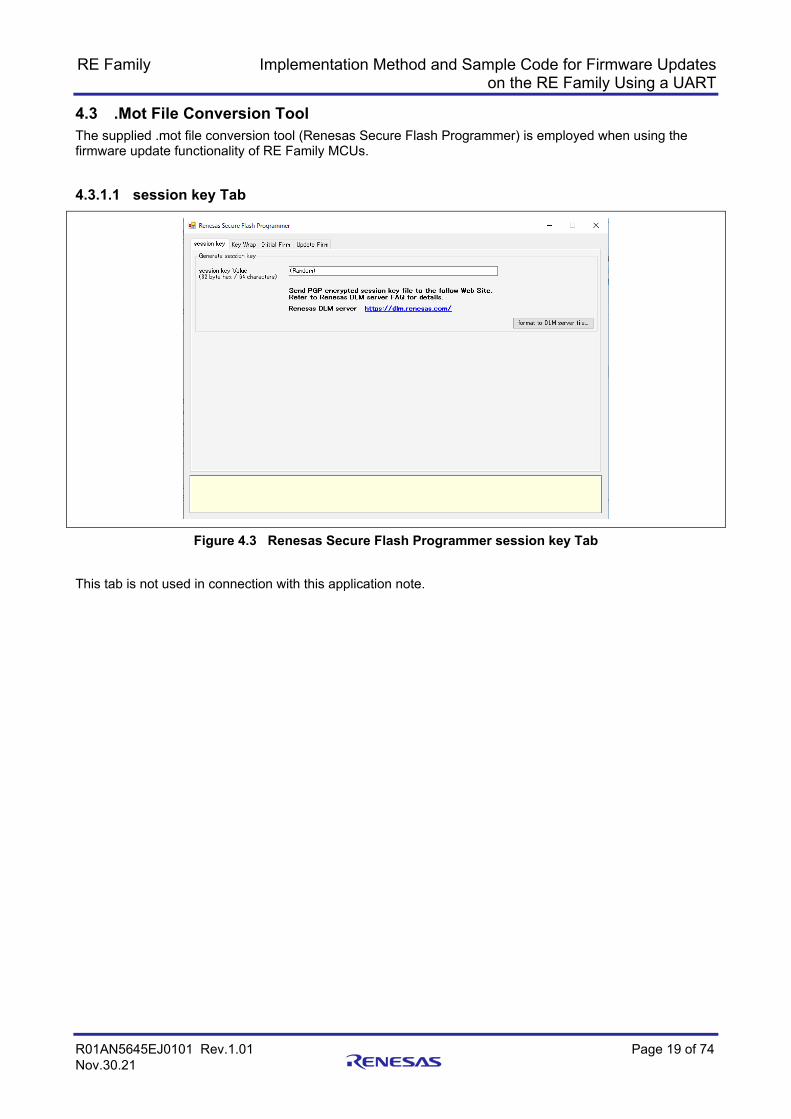
4.3 .Mot File Conversion Tool The supplied .mot file conversion tool (Renesas Secure Flash Programmer) is employed when using the firmware update functionality of RE Family MCUs.
4.3.1.1 session key Tab
Figure 4.3 Renesas Secure Flash Programmer session key Tab
This tab is not used in connection with this application note.

RE Family Implementation Method and Sample Code for Firmware Updates on the RE Family Using a UART
R01AN5645EJ0101 Rev.1.01 Page 20 of 74 Nov.30.21
4.3.1.2 Key Wrap Tab
Figure 4.4 Renesas Secure Flash Programmer Key Wrap Tab
This tab is not used in connection with this application note.

RE Family Implementation Method and Sample Code for Firmware Updates on the RE Family Using a UART
R01AN5645EJ0101 Rev.1.01 Page 21 of 74 Nov.30.21
4.3.1.3 Initial Firm Tab
Figure 4.5 Renesas Secure Flash Programmer Initial Firm Tab
This tab is used to generate the initial firmware installed by the boot firmware.
1. Select MCU
Specify the device to be used and the bootloader size. Value Description Remarks RE01_1500KB/Secure Bootloader = 512KB
Device: RE01-1500KB Bootloader size: 512 KB
The flash ROM BGO function is used when performing the firmware update.
RE01_1500KB/Secure Bootloader = 64KB
Device: RE01-1500KB Bootloader size: 64 KB
The flash ROM BGO function is not used when performing the firmware update.
RE01_256KB/Secure Bootloader = 64KB
Device: RE01-256KB Bootloader size: 64 KB
Other Use by firmware update functionality of RX Family.
Refer to RX Family firmware update application note.
1 2 3 4 5
6
7 8
9
10

RE Family Implementation Method and Sample Code for Firmware Updates on the RE Family Using a UART
R01AN5645EJ0101 Rev.1.01 Page 22 of 74 Nov.30.21
2. Select Firmware Verification Type Specify the method to be used by the bootloader to verify the firmware update.
Value Description Remarks sig-sha256-ecdsa Verification using ECDSA SHA256 Refer to 4.2.3, .Mot File Conversion
Tool, for usage instructions. hash-sha256 Verification by comparing SHA256
hash values
mac-aes128-cmac-with-tsip AES128 CMAC verification using TSIP
Not supported by this version of the software.
sig-sha256-ecdsa-with-tsip ECDSA SHA256 verification using TSIP
Not supported.
3. AES MAC Key
Used when mac-aes128-cmac-with-tsip is selected in step 2. Not supported by this version of the software.
4. Private Key Path
If sig-sha256-ecdsa or sig-sha256-ecdsa-with-tsip was selected in step 2, enter the path to the .pem format file containing the secret key generated as described in 4.2.2.
5. Select Output Format
Select the format of the file to be generated when you click the Generate... button on the Initial Firm tab. Value Description Remarks Bank0 User Program (Binary Format)
Generates an application program to be input to the user program area by the bootloader.
File output in .rsu format
Bank0 User Program + Bootloader (Motorola S Format)
Outputs a Motorola S format file containing both the bootloader and the application program for the user program area.
Bank0 & Bank1 User Program + Bootloader (Motorola S Format)
Outputs a Motorola S format file containing the bootloader and the application program for the user program area and temporary area.
Not supported by this version of the software.
6. Bootloader File Path (Motorola Format)
If Bank0 User Program + Bootloader (Motorola S Format) was selected in step 5, enter the path to the Motorola S Format file containing the boot firmware.
7. Bank 0 User program — Firmware Sequence Number
Specify the sequence number of the user program. Not supported by this version of the software. 8. Bank 0 User Program — File Path (Motorola S Format)
Specify the path for the Motorola S Format file containing the user program used by the initial firmware generated from this tab.
9. Bank 1 User Program
If Bank0 & Bank1 User Program + Bootloader (Motorola S Format) was selected in step 5, enter the path for the Motorola S Format file to be written to the temporary area.
10. Generate button
Generates an .rsu format file or Motorola S Format file containing the initial firmware.
RE Family Implementation Method and Sample Code for Firmware Updates on the RE Family Using a UART
R01AN5645EJ0101 Rev.1.01 Page 23 of 74 Nov.30.21
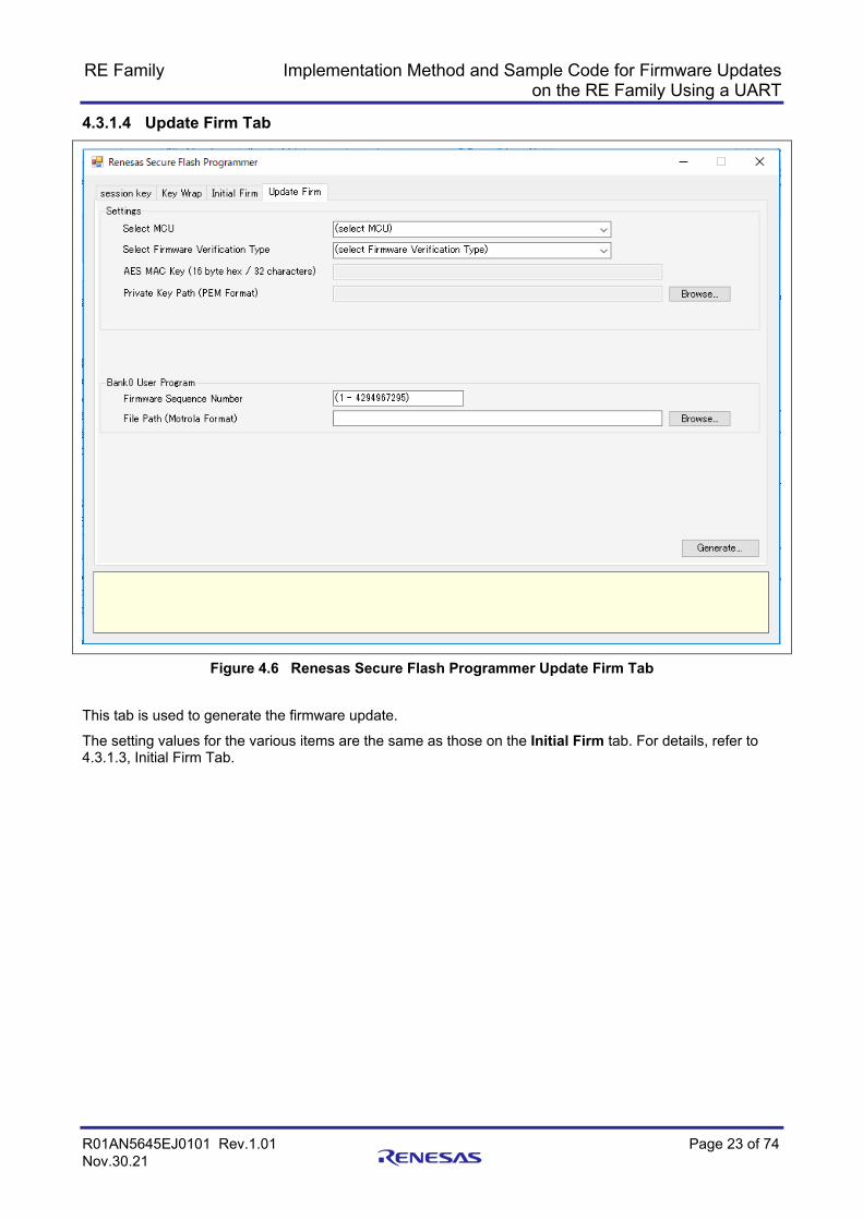
4.3.1.4 Update Firm Tab
Figure 4.6 Renesas Secure Flash Programmer Update Firm Tab
This tab is used to generate the firmware update.
The setting values for the various items are the same as those on the Initial Firm tab. For details, refer to 4.3.1.3, Initial Firm Tab.

RE Family Implementation Method and Sample Code for Firmware Updates on the RE Family Using a UART
R01AN5645EJ0101 Rev.1.01 Page 24 of 74 Nov.30.21
5. Operation of Sample Program The method used to confirm the operation of the sample program using firmware update functionality is described in this section. Use of the sample program without BGO on the RE01-1500KB EK board is described. The sample program with BGO for the RE01-1500KB EK board and the sample program for the RE01-256KB EK board both operate similarly.
In the firmware update process for an RE Family MCU as described in this application note, the updated user program is sent from the PC using Tera Term and received by the UART on the board, after which the firmware update is applied, as shown in Figure 5.1.
User program V.1.01
USB cable
User program V.1.00
Motorola file
Motorola convert tool
User program V.1.00
Bootloader
RE01 flash memory program
[1]
[1]
[2]
[1]
User program area
Bootloader area
Tempraryarea
JFlashLite
Bootloader Motorola file
SWDUSB-serial
UART
User program V.1.01
Motorola file
[2]
Boot Loader
User program V.1.01
Boot Loader
User program V.1.01
Boot Loader
User program V.1.01
From UART
Copy
Initial firmware programmed at the factory.
New firmware updated in the field.
[2]
[2][2]
[1]
Figure 5.1 System Configuration: Overall View

RE Family Implementation Method and Sample Code for Firmware Updates on the RE Family Using a UART
R01AN5645EJ0101 Rev.1.01 Page 25 of 74 Nov.30.21
5.1 Preparation In the description below, the RE01-1500KB EK board is used as an example. The procedure when using the RE01-256KB is similar. Refer to 2.1 for information on connections. Other necessary equipment and software used for confirming operation are listed in Table 5.1.
Table 5.1 Necessary Items for Confirming Operation of Sample Program
Item Remarks RE01-1500KB Evaluation Kit Board USB cable (micro) Two cables are needed when using the JLink OB as a debugger. PC Windows PC Tera Term Download the software from the following webpage and install it
on the PC. https://ttssh2.osdn.jp/
Motorola convert file GUI distributed with this application note that runs on the PC. e2 studio Refer to 1.4, Development Environment. GCC Refer to 1.4, Development Environment. JFlash Lite Download “JLink Software and Documentation Pack” from the
following webpage and install JLink Software Pack, which includes JFlash Lite, on the PC. https://www.segger.com/products/debug-probes/j-link/technology/flash-download/

RE Family Implementation Method and Sample Code for Firmware Updates on the RE Family Using a UART
R01AN5645EJ0101 Rev.1.01 Page 26 of 74 Nov.30.21
5.2 Sample Software Operation Instructions Operation instructions for the sample software are provided below.
5.2.1 Creating a Motorola File Containing the Bootloader and User Programs Use e2 studio to create a Motorola file containing the bootloader and versions V.1.00 and V.1.01 of the user program. User program V.1.01 is intended to be used for updates performed in the field, but the file created using the procedure described below contains user program V.1.01 as well as the bootloader and user program V.1.00.
User program V.1.01
USB cable
User program V.1.00
Motorola file
Motorola convert tool
User program V.1.00
Bootloader
RE01 flash memory program
[1]
[1]
[2]
[1]
User program area
Bootloader area
Temprary area
JFlashLite
Bootloader Motorola file
SWDUSB-serial
UART
User program V.1.01
Motorola file
[2]
Bootloader
User program V.1.01
Bootloader
User program V.1.01
Bootloader
User program V.1.01
From UART
Copy
Initial firmware programmed at the factory.
New firmware updated in the field.
[2]
[2][2]
[1]
Figure 5.2 System Configuration: Overall View — Bootloader and User Program Procedure

RE Family Implementation Method and Sample Code for Firmware Updates on the RE Family Using a UART
R01AN5645EJ0101 Rev.1.01 Page 27 of 74 Nov.30.21
1. Launch e2 studio and import the following three projects: re01_1500kb_ek_bootloader, re01_1500kb_ek_fwup_user_application_v100, and re01_1500kb_ek_fwup_user_application_v101. In e2 studio, select File → Import, then import the projects from the Import window.
Figure 5.3 Importing Three Projects into e2 studio 2. Build the three projects you just imported.
Figure 5.4 Selecting and Building Projects in e2 studio

RE Family Implementation Method and Sample Code for Firmware Updates on the RE Family Using a UART
R01AN5645EJ0101 Rev.1.01 Page 28 of 74 Nov.30.21
3. After building the projects, confirm that the HardwareDebug folder of each project contains a Motorola S format file with the extension .srec.
Figure 5.5 Confirming Motorola File in Project Explorer

RE Family Implementation Method and Sample Code for Firmware Updates on the RE Family Using a UART
R01AN5645EJ0101 Rev.1.01 Page 29 of 74 Nov.30.21
5.2.2 Creating a Motorola File Containing the Bootloader and User Program V.1.00 Create a Motorola file (combined .mot file) containing the bootloader and user program V.1.00.
User program V.1.01
USB cable
User program V.1.00
Motorola file
Motorola convert tool
User program V.1.00
Bootloader
RE01 flash memory program
[1]
[1]
[2]
[1]
User program area
Bootloader area
Temprary area
JFlashLite
Bootloader Motorola file
SWDUSB-serial
UART
User program V.1.01
Motorola file
[2]
Boot Loader
User program V.1.01
Boot Loader
User program V.1.01
Boot Loader
User program V.1.01
From UART
Copy
Initial firmware programmed at the factory.
New firmware updated in the field.
[2]
[2][2]
[1]
Figure 5.6 System Configuration: Overall View — Creating Combined .Mot File Containing Bootloader and User Program V.1.00

RE Family Implementation Method and Sample Code for Firmware Updates on the RE Family Using a UART
R01AN5645EJ0101 Rev.1.01 Page 30 of 74 Nov.30.21
1. Use the Motorola convert tool to create a combined .mot file containing the bootloader and user program V.1.00 that will be written to the board using JLink Lite. Unzip the file renesas_secure_flash_programmer.zip, located in the tools folder in the product package, then launch Renesas Secure Flash Programmer.exe, located in the Renesas Secure Flash Programmer\bin\Debug folder. Open the Initial Firm tab. Enter settings as shown in Figure 5.7, and generate userprog_V100.mot.
Figure 5.7 Renesas Secure Flash Programmer Initial Tab Settings
Item Setting Value Setting Select MCU RE01_1500KB/Secure Bootloader=64KB
Select Firmware Verification Type
hash-sha256
Select Output Format Bank 0 User Program + Bootloader (Motorola S Format) Boot Loader File Path (Motorola Format) The path to the file re01_1500kb_ek_bootloader.srec
created by building the re01_1500kb_ek_bootloader project in e2 studio.
Bank0 User Program
Firmware Sequence Number 1 File Path (Motorola Format) The path to the file
re01_1500kb_ek_fwup_user_application_V100.srec created by building the re01_1500kb_ek_fwup_user_application_V100 project in e2 studio.
2. Click the Generate... button to create the *.mot file.
Output the file userprog_V100.mot to a folder of your choice.

RE Family Implementation Method and Sample Code for Firmware Updates on the RE Family Using a UART
R01AN5645EJ0101 Rev.1.01 Page 31 of 74 Nov.30.21
5.2.3 Creating a Firmware Update File (.rsu File) Use the Motorola convert tool to convert the user program to a firmware update file (.rsu file). User program V.1.01 is intended to be used for updates performed in the field, but the file created using the procedure described below contains user program V.1.01 as well as the bootloader and user program V.1.00.
User program V.1.01
USB cable
User program V.1.00
Motorola file
Motorola convert tool
User program V.1.00
Bootloader
RE01 flash memory program
[1]
[1]
[2]
[1]
User program area
Bootloader area
Temprary area
JFlashLite
Bootloader Motorola file
SWDUSB-serial
UART
User program V.1.01
Motorola file
[2]
Boot Loader
User program V.1.01
Boot Loader
User program V.1.01
Boot Loader
User program V.1.01
From UART
Copy
Initial firmware programmed at the factory.
New firmware updated in the field.
[2]
[2][2]
[1]
Figure 5.8 System Configuration: Overall View — Creating a Firmware Update File

RE Family Implementation Method and Sample Code for Firmware Updates on the RE Family Using a UART
R01AN5645EJ0101 Rev.1.01 Page 32 of 74 Nov.30.21
1. Use the Motorola convert tool to create a .rsu file to be used to update the firmware. Launch Renesas Secure Flash Programmer.exe and open the Update Firm tab. Enter settings as shown in Figure 5.9, and generate userprog_V101.rsu.
Figure 5.9 Renesas Secure Flash Programmer Settings
Item Setting Value Setting Select MCU RE01_1500KB/Secure Bootloader=64KB
Select Firmware Verification Type
hash-sha256
Bank0 User Program
Firmware Sequence Number 1 File Path (Motorola Format) The path to the file
re01_1500kb_ek_fwup_user_application_V101.srec created by building the re01_1500kb_ek_fwup_user_application_V101 project in e2 studio.
2. Click the Generate... button to create the *.rsu file.
Output the file userprog_V101.rsu to a folder of your choice.
RE Family Implementation Method and Sample Code for Firmware Updates on the RE Family Using a UART
R01AN5645EJ0101 Rev.1.01 Page 33 of 74 Nov.30.21
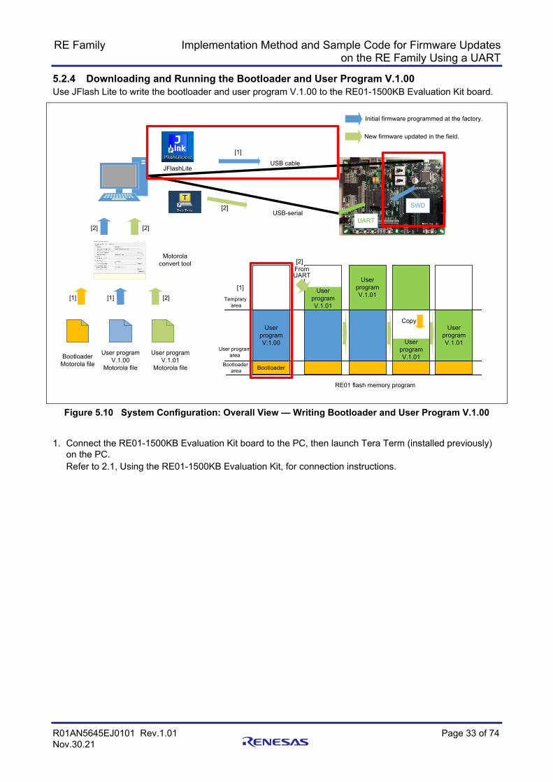
5.2.4 Downloading and Running the Bootloader and User Program V.1.00 Use JFlash Lite to write the bootloader and user program V.1.00 to the RE01-1500KB Evaluation Kit board.
User program V.1.01
USB cable
User program V.1.00
Motorola file
Motorola convert tool
User program V.1.00
Bootloader
RE01 flash memory program
[1]
[1]
[2]
[1]
User program area
Bootloader area
Temprary area
JFlashLite
Bootloader Motorola file
SWDUSB-serial
UART
User program V.1.01
Motorola file
[2]
Bootloader
User program V.1.01
Bootloader
User program V.1.01
Bootloader
User program V.1.01
From UART
Copy
Initial firmware programmed at the factory.
[2]
[2][2]
[1]
New firmware updated in the field.
Figure 5.10 System Configuration: Overall View — Writing Bootloader and User Program V.1.00
1. Connect the RE01-1500KB Evaluation Kit board to the PC, then launch Tera Term (installed previously)
on the PC. Refer to 2.1, Using the RE01-1500KB Evaluation Kit, for connection instructions.

RE Family Implementation Method and Sample Code for Firmware Updates on the RE Family Using a UART
R01AN5645EJ0101 Rev.1.01 Page 34 of 74 Nov.30.21
2. In Tera Term, select File → New connection. Select Serial, and USB Serial Port is displayed as a virtual COM port. Accept the selection by clicking OK.
Figure 5.11 Tera Term Virtual COM Port Setting 3. Select Setup → Serial port.... Set the baud rate (Speed) to 115200 and click the New setting button.
Figure 5.12 Serial Port Settings

RE Family Implementation Method and Sample Code for Firmware Updates on the RE Family Using a UART
R01AN5645EJ0101 Rev.1.01 Page 35 of 74 Nov.30.21
4. Launch JFlash Lite. Refer to 2.1, Using the RE01-1500KB Evaluation Kit, for connection instructions. To launch JFlash Lite, locate JFlashLite.exe in the install folder of JLink Software and Documentation Pack from Segger and run it. The default install folder of JLink Software and Documentation Pack is C:\Program Files (x86)\SEGGER\JLink.
5. When the following information dialog box appears, click the O.K. button.
Figure 5.13 J-Flash Lite Info Dialog Box 6. To select the Device, click the ... button.
Figure 5.14 J-Flash Lite Startup Screen Dialog Box
Figure 5.15 J-Flash Lite Device Settings Dialog Box

RE Family Implementation Method and Sample Code for Firmware Updates on the RE Family Using a UART
R01AN5645EJ0101 Rev.1.01 Page 36 of 74 Nov.30.21
In the Target Device Settings dialog box, select the following device and click the OK button. Manifacturer: Renesas Device: R7F0E015D
Figure 5.16 J-Flash Lite Startup Screen Dialog Box — After Device Selection
Click the OK button. The following J-Flash Lite window opens.
7. Select the program to download. Click the ... button under Data File, then select userprog_V100.mot.
Figure 5.17 J-Flash Lite Dialog Box — Selecting Program to Download

RE Family Implementation Method and Sample Code for Firmware Updates on the RE Family Using a UART
R01AN5645EJ0101 Rev.1.01 Page 37 of 74 Nov.30.21
8. Erasing Data from On-Chip ROM Click the Erase Chip button to erase data from all areas of the on-chip flash ROM.
Figure 5.18 J-Flash Lite Dialog Box — Erasing On-Chip ROM Data 9. Download and run the program.
Click the Program Device button to download the program to the MCU.
Figure 5.19 J-Flash Lite Dialog Box — Downloading Program

RE Family Implementation Method and Sample Code for Firmware Updates on the RE Family Using a UART
R01AN5645EJ0101 Rev.1.01 Page 38 of 74 Nov.30.21
Once the download finishes, the program runs automatically. Confirm that the following information is displayed in Tera Term.
Figure 5.20 Tera Term — Bootloader and User Program V.1.00 Execution Result
The portion up to and including “Jump to user program” reflects the operation of the bootloader. Confirm that “Version ver 1.00” is displayed by the user program.
User program V.1.00
Boottloader

RE Family Implementation Method and Sample Code for Firmware Updates on the RE Family Using a UART
R01AN5645EJ0101 Rev.1.01 Page 39 of 74 Nov.30.21
5.2.5 Downloading the User Program Update Use Tera Term to update the user program from V.1.00 to V.1.01.
User program V.1.01
USB cable
User program V.1.00
Motorola file
Motorola convert tool
User program V.1.00
Bootloader
RE01 flash memory program
[1]
[1]
[2]
[1]
User program area
Bootloader area
Temprary area
JFlashLite
Bootloader Motorola file
SWDUSB-serial
UART
User program V.1.01
Motorola file
[2]
Bootloader
User program V.1.01
Bootloader
User program V.1.01
Bootloader
User program V.1.01
From UART
Copy
Initial firmware programmed at the factory.
New firmware updated in the field.
[2]
[2][2]
[1]
Figure 5.21 System Configuration: Overall View — Updating to User Program V.1.01

RE Family Implementation Method and Sample Code for Firmware Updates on the RE Family Using a UART
R01AN5645EJ0101 Rev.1.01 Page 40 of 74 Nov.30.21
1. “Send Update firmware via UART.” is displayed in Tera Term.
Figure 5.22 User Program V.1.00 — Waiting to Download Firmware Update 2. Use the send file function of Tera Term to transfer userprog_V101.rsu. In Tera Term, select File →
Send file.... Place a check next to Binary under Option, then send the file userprog_V101.rsu created as described in 5.2.3, Creating a Firmware Update File (.rsu File).
Figure 5.23 Send File Settings

RE Family Implementation Method and Sample Code for Firmware Updates on the RE Family Using a UART
R01AN5645EJ0101 Rev.1.01 Page 41 of 74 Nov.30.21
3. When updating of the firmware finishes, “jump to user program” is displayed and a jump to the updated user application occurs. After the update finishes, the firmware version changes from ver 1.00 to ver 1.01.
Figure 5.24 Display After Firmware Update
User program V.1.01
Boottloader

RE Family Implementation Method and Sample Code for Firmware Updates on the RE Family Using a UART
R01AN5645EJ0101 Rev.1.01 Page 42 of 74 Nov.30.21
5.3 Switching the RE01-1500KB Sample Software from Not Using BGO to Using BGO
The three sample software projects re01_1500kb_ek_bootloader, re01_1500kb_ek_fwup_user_application_v100, and re01_1500kb_ek_fwup_user_application_v101 all do not use BGO. Follow the steps outlined below to change the projects so that BGO is used.
1. Make the switch for each project. A linker script file for switching the above three projects to use BGO is provided. Follow the steps below to make the switch. Select the project to be switched and select Project → Properties to display the Properties window.
Figure 5.25 e2 studio — Selecting Properties
In the toolbar on the left of the Properties window, select C/C++ Build and click the Manage Configurations... button.
Figure 5.26 e2 studio — Properties Window

RE Family Implementation Method and Sample Code for Firmware Updates on the RE Family Using a UART
R01AN5645EJ0101 Rev.1.01 Page 43 of 74 Nov.30.21
In the Manage Configurations window, select HardwareDebug_bootloader512kb for Configuration and click the Set Active button.
Figure 5.27 e2 studio — Manage Configurations Window
Confirm that the Status is shown as Active for Configuration: HardwareDebug_bootloader512kb. After confirming, click the OK button to close the Manage Configurations window.
Figure 5.28 e2 studio Manage Configurations Window — Status Switched to Active

RE Family Implementation Method and Sample Code for Firmware Updates on the RE Family Using a UART
R01AN5645EJ0101 Rev.1.01 Page 44 of 74 Nov.30.21
In the Configuration: pull-down menu in the Properties window, confirm that HardwareDebug_bootloader512kb is listed as Active, then select HardwareDebug_bootloader512kb. Click the Apply and Close button to close the Properties window.
Figure 5.29 e2 studio — Changing Enabled Setting in Properties Window 2. Change setting in flash driver.
For each of the three projects, make the following change in Device\Config\r_flash_cfg.h.
Before change: #define FLASH_CFG_CODE_FLASH_RUN_FROM_ROM (0) After change: #define FLASH_CFG_CODE_FLASH_RUN_FROM_ROM (1)
3. Make additional driver settings.
In the xxx_cfg.h file in Device\Config for each of the three projects, modify the definitions of the APIs to enable execution from RAM.
RAM execution: #define API definition name (SYSTEM_SECTION_CODE) ROM execution: #define API definition name (SYSTEM_SECTION_RAM_FUNC)

RE Family Implementation Method and Sample Code for Firmware Updates on the RE Family Using a UART
R01AN5645EJ0101 Rev.1.01 Page 45 of 74 Nov.30.21
6. API Information
6.1 Supported Toolchain The firmware updater driver has been confirmed to work with the following toolchain.
GCC ARM Embedded Version 6.3.1.20170620
6.2 Header Files All API calls and their supporting interface definitions are located in r_fwup_api.h.
6.3 Integer Types This project uses ANSI C99.

RE Family Implementation Method and Sample Code for Firmware Updates on the RE Family Using a UART
R01AN5645EJ0101 Rev.1.01 Page 46 of 74 Nov.30.21
6.4 Configuration Overview The settings for various functions can be changed by changing the macro values listed below in Device/Config/r_fwup_cfg.h.
Configuration options in r_config/r_fwup_cfg.h Definition Default Value Remarks FWUP_CFG_IMPLEMENTATION_ENVIRONMENT
0: 1:
Selects the implementation environment. 0: Bootloader 1: Firmware update functionality
(without OS) 2: Firmware update functionality
(Amazon FreeRTOS OTA) (not supported)
3: Firmware update functionality (other RTOS) (not supported)
FWUP_CFG_COMMUNICATION_FUNCTION 0 Selects the communication module. 0: SCI connection 1: Ethernet connection (not supported) 2: USB connection (not supported) 3: SDHI connection (not supported) 4: QSPI connection (not supported)
FWUP_CFG_UART UASART channel used for SCI connection Driver_USART4 for RE01-1500KB Driver_USART0 for RE01-256KB
FWUP_CFG_SIGNATURE_VERIFICATION 1 Boot firmware verification method 0: ECDSA 1: SHA256
FWUP_CFG_BOOT_PROTECT_ENABLE 0 Bootloader protection 0: Disabled 1: Enabled
FWUP_CFG_FUNCSECTION_ROM 0 Firmware update API execution area 0: RAM 1: ROM
6.5 API Data Structure Refer to r_fwup_api.h for information regarding the data structure used by the firmware updater driver.
6.6 Return Values This section describes return values of API functions. This enumeration is located in r_fwup_api.h as are the prototype declarations of API functions.

RE Family Implementation Method and Sample Code for Firmware Updates on the RE Family Using a UART
R01AN5645EJ0101 Rev.1.01 Page 47 of 74 Nov.30.21
7. API Functions The API functions included in the firmware update functionality are listed below. The APIs available for use differ depending which of the three available patterns (bootloader, user program, or FreeRTOS with IoT Library OTA) is used. Table 7.1 lists the program with which each API can be used.
Table 7.1 APIs Included in Firmware Update Functionality
API Description Bootloader User Program FreeRTOS
R_FWUP_SecureBoot Processing of bootloader portion
R_FWUP_ExecuteFirmware User application startup R_FWUP_Open Initialization of firmware
update functionality
R_FWUP_Close Termination of firmware update functionality
R_FWUP_Operation Firmware update functionality update processing
R_FWUP_SoftwareReset Software reset execution R_FWUP_SetEndOfLife User application end of life
processing
R_FWUP_CreateFileForRx OTA initial settings R_FWUP_Abort OTA update processing
abort
R_FWUP_WriteBlock Writing of data block R_FWUP_CloseFile Closing of specified file R_FWUP_CheckFileSignature Signature verification for
specified file
R_FWUP_ResetDevice Device reset R_FWUP_ActiveNewImage New firmware startup R_FWUP_SetPlatformImageState Life cycle state setting R_FWUP_GetPlatformImageState Current life cycle check R_FWUP_GetVersion Version information check

RE Family Implementation Method and Sample Code for Firmware Updates on the RE Family Using a UART
R01AN5645EJ0101 Rev.1.01 Page 48 of 74 Nov.30.21
7.1 Bootloader APIs The APIs used to provide bootloader functionality are described below.
7.1.1 R_FWUP_SecureBoot This API performs secure boot processing for the bootloader.
It obtains the firmware data to be installed via the communication pathway specified in the configuration settings, programs the flash memory, and performs signature verification.
Format fwup_err_t R_FWUP_SecureBoot(void)
Arguments None.
Return Values FWUP_SUCCESS Update successful FWUP_FAIL Update failed FWUP_IN_PROGRESS Update in progress Description This API performs processing for the bootloader portion of the firmware update functionality.
It checks the state of the user program area and temporary area, and performs appropriate processing according to the state of each.
Processing is advanced step by step by calling this API multiple times.
Special Notes: A return value of FWUP_IN_PROGRESS means that the secure boot is still in progress, so call the function again in this case.
A return value of FWUP_SUCCESS means that the secure boot has completed. In this case, call the R_FWUP_ExecuteFirmware function to have processing jump to the initially installed or the updated firmware.
A return value of FWUP_FAIL means that the secure boot has failed. In this case, clear the error if necessary and then call the function again.

RE Family Implementation Method and Sample Code for Firmware Updates on the RE Family Using a UART
R01AN5645EJ0101 Rev.1.01 Page 49 of 74 Nov.30.21
7.1.2 R_FWUP_ExecuteFirmware This function causes processing to jump to the initially installed or the updated firmware.
Format void R_FWUP_ExecuteFirmware(void)
Arguments None.
Return Values None.
Description Causes processing to jump to the initially installed or the updated firmware.
Calling this API once causes processing to jump to the firmware.
Special Notes:

RE Family Implementation Method and Sample Code for Firmware Updates on the RE Family Using a UART
R01AN5645EJ0101 Rev.1.01 Page 50 of 74 Nov.30.21
7.2 User Program Update APIs The APIs used to provide user program firmware update functionality are described below.
7.2.1 R_FWUP_Open This API function initializes the firmware update functionality.
It performs processing to open resources used for the firmware update, makes initial OS settings (when using an OS), and performs processing to initialize various variables.
Format fwup_err_t R_FWUP_Open(void)
Arguments None.
Return Values FWUP_SUCCESS Normal end FWUP_ERR_ALREADY_OPEN Already initialized FWUP_ERR_COMM Communication module error FWUP_ERR_STATE_MONITORING State monitoring module error FWUP_ERR_FLASH Flash memory module error FWUP_ERR_IMAGE_STATE Cannot update flash memory state
Description This API initializes the firmware update functionality.
After the API is called, the firmware update functionality is ready for use.
Special Notes: After this API is called once, it cannot be called again until R_FWUP_Close has been called.
To call R_FWUP_Open again, first call R_FWUP_Close and then call R_FWUP_Open.

RE Family Implementation Method and Sample Code for Firmware Updates on the RE Family Using a UART
R01AN5645EJ0101 Rev.1.01 Page 51 of 74 Nov.30.21
7.2.2 R_FWUP_Close This API function performs processing to terminate the firmware update functionality.
Format fwup_err_t R_FWUP_Close (void)
Arguments None.
Return Values FWUP_SUCCESS Normal end FWUP_ERR_NOT_OPEN Firmware update functionality not initialized Description This API performs processing to terminate the firmware update functionality.
It performs processing to close resources used by the firmware update functionality.
Special Notes: Call this API after R_FWUP_Open has been called.
An error occurs if it is called before R_FWUP_Open.

RE Family Implementation Method and Sample Code for Firmware Updates on the RE Family Using a UART
R01AN5645EJ0101 Rev.1.01 Page 52 of 74 Nov.30.21
7.2.3 R_FWUP_Operation This API function performs user application firmware update processing.
Format fwup_err_t R_FWUP_Operation (void)
Arguments None.
Return Values FWUP_SUCCESS Firmware update successful FWUP_IN_PROGRESS Firmware update in progress FWUP_FAIL Firmware update failed FWUP_ERR_NOT_OPEN Firmware update functionality not initialized FWUP_ERR_IMAGE_STATE Cannot update flash memory state FWUP_ERR_STATE_MONITORING Update state has not changed for more than specified period of time Description This API performs processing for the firmware update portion of the firmware update functionality.
It obtains the firmware data to be used for the update via the communication pathway specified in the configuration settings, programs the flash memory, and performs signature verification.
Special Notes: The firmware cannot be updated if the state of the flash memory area to be updated is other than VALID or INITIAL_FIRM_INSTALLED, so a value of FWUP_ERR_STATE is returned.
A return value of FWUP_IN_PROGRESS means that the firmware update is still in progress, so call the function again in this case.
A return value of FWUP_SUCCESS means that the firmware update has completed. In this case, call the R_FWUP_SoftwareReset function. This will perform a software reset, causing processing to jump to the updated firmware.
A return value of FWUP_FAIL means that the firmware update has failed. In this case, clear the error and then call the function again.

RE Family Implementation Method and Sample Code for Firmware Updates on the RE Family Using a UART
R01AN5645EJ0101 Rev.1.01 Page 53 of 74 Nov.30.21
7.2.4 R_FWUP_SetEndOfLife This API function performs user application end of life processing.
Format fwup_err_t R_FWUP_SetEndOfLife(void)
Arguments None.
Return Values FWUP_SUCCESS Normal end FWUP_ERR_FLASH Error occurred in flash memory module FWUP_ERR_COMM Error occurred in communication module Description This API performs user application end of life processing.
Special Notes:

RE Family Implementation Method and Sample Code for Firmware Updates on the RE Family Using a UART
R01AN5645EJ0101 Rev.1.01 Page 54 of 74 Nov.30.21
7.2.5 R_FWUP_SoftwareReset This API function performs a software reset.
Format void R_FWUP_SoftwareReset (void)
Arguments None.
Return Values None.
Description This API performs a software reset.
After the software reset, operation starts from the reset vector.
Special Notes:

RE Family Implementation Method and Sample Code for Firmware Updates on the RE Family Using a UART
R01AN5645EJ0101 Rev.1.01 Page 55 of 74 Nov.30.21
7.3 APIs Used with FreeRTOS with IoT Library OTA The APIs used with FreeRTOS with IoT Library OTA are described below.
These APIs are not supported by this version of the software.
7.3.1 R_FWUP_CreateFileForRx This API function is used by the OTA functionality of FreeRTOS with IoT Library.
Format OTA_Err_t R_FWUP_CreateFileForRx( OTA_FileContext_t * const C )
Arguments OTA_FileContext_t * const C File context
Return Values kOTA_Err_None Normal end kOTA_Err_RxFileCreateFailed File creation error Description This API function is used with the OTA functionality of FreeRTOS with IoT Library.
It is not supported by this version of the software.
Special Notes:

RE Family Implementation Method and Sample Code for Firmware Updates on the RE Family Using a UART
R01AN5645EJ0101 Rev.1.01 Page 56 of 74 Nov.30.21
7.3.2 R_FWUP_Abort This API function aborts OTA update processing.
Format OTA_Err_t R_FWUP_Abort( OTA_FileContext_t * const C )
Arguments OTA_FileContext_t * const C File context Return Values kOTA_Err_None Normal end kOTA_Err_FileClose File context close error Description This API aborts OTA update processing.
It is not supported by this version of the software.
Special Notes:

RE Family Implementation Method and Sample Code for Firmware Updates on the RE Family Using a UART
R01AN5645EJ0101 Rev.1.01 Page 57 of 74 Nov.30.21
7.3.3 R_FWUP_WriteBlock
Format int16_t R_FWUP_WriteBlock( OTA_FileContext_t * const C,
uint32_t ulOffset,
uint8_t * const pacData,
uint32_t ulBlockSize )
Arguments OTA_FileContext_t * const C uint32_t ulOffset uint8_t * const pacData uint32_t ulBlockSize Return Values sNumBytesWritten Block size R_OTA_ERR_QUEUE_SEND_FAIL Failure Description This API function is used with the OTA functionality of FreeRTOS with IoT Library.
It is not supported by this version of the software.
Special Notes:

RE Family Implementation Method and Sample Code for Firmware Updates on the RE Family Using a UART
R01AN5645EJ0101 Rev.1.01 Page 58 of 74 Nov.30.21
7.3.4 R_FWUP_CloseFile This API function closes the specified file.
It performs signature verification on the firmware downloaded to the buffer area in the temporary area.
It also writes the header information of the buffer area in the temporary area.
Format OTA_Err_t R_FWUP_CloseFile( OTA_FileContext_t * const C )
Arguments OTA_FileContext_t * const C Return Values kOTA_Err_None Normal end kOTA_Err_Panic Life cycle has not changed for more than specified period of time kOTA_Err_FileClose File close error kOTA_Err_SignatureCheckFailed Signature verification error Description This API function is used with the OTA functionality of FreeRTOS with IoT Library.
It is not supported by this version of the software.
Special Notes:

RE Family Implementation Method and Sample Code for Firmware Updates on the RE Family Using a UART
R01AN5645EJ0101 Rev.1.01 Page 59 of 74 Nov.30.21
7.3.5 R_FWUP_CheckFileSignature This API function checks the signature of the specified file.
Format OTA_Err_t R_FWUP_CheckFileSignature( OTA_FileContext_t * const C )
Arguments OTA_FileContext_t * const C Return Values kOTA_Err_None Normal end kOTA_Err_BadSignerCert Certificate error kOTA_Err_SignatureCheckFailed Signature verification error Description This API function is used with the OTA functionality of FreeRTOS with IoT Library.
It is not supported by this version of the software.
Special Notes:

RE Family Implementation Method and Sample Code for Firmware Updates on the RE Family Using a UART
R01AN5645EJ0101 Rev.1.01 Page 60 of 74 Nov.30.21
7.3.6 R_FWUP_ReadAndAssumeCertificate Reads from the file system and returns the specified signer certificate.
Format uint8_t * R_FWUP_ReadAndAssumeCertificate( const uint8_t * const pucCertName, uint32_t * const ulSignerCertSize ) Arguments const uint8_t * const pucCertName Certificate file name uint32_t * const ulSignerCertSize Certificate size Return Values pucSignerCert Pointer to certificate data
Description This API function is used with the OTA functionality of FreeRTOS with IoT Library.
It is not supported by this version of the software.
Special Notes:
RE Family Implementation Method and Sample Code for Firmware Updates on the RE Family Using a UART
R01AN5645EJ0101 Rev.1.01 Page 61 of 74 Nov.30.21
7.3.7 R_FWUP_ResetDevice This API function resets the device.
Format OTA_Err_t R_FWUP_ResetDevice( void )
Arguments None.
Return Values kOTA_Err_None Normal end
Description This API function is used with the OTA functionality of FreeRTOS with IoT Library.
It is not supported by this version of the software.
Special Notes:

RE Family Implementation Method and Sample Code for Firmware Updates on the RE Family Using a UART
R01AN5645EJ0101 Rev.1.01 Page 62 of 74 Nov.30.21
7.3.8 R_FWUP_ActivateNewImage This API function activates or launches the new firmware.
When the API is called, it generates a software reset and then launches the new firmware via bootloader processing.
Format OTA_Err_t R_FWUP_ActivateNewImage( void )
Arguments None.
Return Values kOTA_Err_None Normal end
Description This API function is used with the OTA functionality of FreeRTOS with IoT Library.
It is not supported by this version of the software.
Special Notes:

RE Family Implementation Method and Sample Code for Firmware Updates on the RE Family Using a UART
R01AN5645EJ0101 Rev.1.01 Page 63 of 74 Nov.30.21
7.3.9 R_FWUP_SetPlatformImageState This API function sets the life cycle state to that specified in the parameters.
If the update to the new firmware has finished, the buffer area in the temporary area is erased.
Format OTA_Err_t R_FWUP_SetPlatformImageState( OTA_ImageState_t eState )
Arguments OTA_ImageState_t eState Specified life cycle state Return Values kOTA_Err_None Normal end kOTA_Err_CommitFailed Commit error kOTA_Err_BadImageState Invalid firmware state value
Description This API function is used with the OTA functionality of FreeRTOS with IoT Library.
It is not supported by this version of the software.
Special Notes:

RE Family Implementation Method and Sample Code for Firmware Updates on the RE Family Using a UART
R01AN5645EJ0101 Rev.1.01 Page 64 of 74 Nov.30.21
7.3.10 R_FWUP_GetPlatformImageState This API function returns the current life cycle state.
Format OTA_PAL_ImageState_t R_FWUP_GetPlatformImageState( void ) Arguments None.
Return Values ePalState Current life cycle state
Description This API function is used with the OTA functionality of FreeRTOS with IoT Library.
It is not supported by this version of the software.
Special Notes:

RE Family Implementation Method and Sample Code for Firmware Updates on the RE Family Using a UART
R01AN5645EJ0101 Rev.1.01 Page 65 of 74 Nov.30.21
7.3.11 R_FWUP_GetVersion This API function returns the version number of the module.
It is not used by the RE firmware update functionality.
Format OTA_Err_t R_FWUP_GetVersion(void)
Arguments None.
Return Values Version information
Description This API function is used with the OTA functionality of FreeRTOS with IoT Library.
It is not supported by this version of the software.
Special Notes:

RE Family Implementation Method and Sample Code for Firmware Updates on the RE Family Using a UART
R01AN5645EJ0101 Rev.1.01 Page 66 of 74 Nov.30.21
8. Firmware Update Operation Details 8.1 Processing Sequence at Bootloader Startup The bootloader references the image flags, which indicate the states of the download format areas of the user program area and temporary area, and determines the operation to perform. The various combinations of user program area and temporary area states are listed below.
Combinations other than those listed below are judged to be states in which a firmware update cannot take place, and an error is generated.
Table 8.1 Bootloader State Flags
Image Flag
State User Program Area
Temporary Area
TESTING (0xfe)
Validation of the firmware installed in the temporary area is in progress.
VALID (0xf8)
Validation of the firmware installed in the temporary area has been completed successfully, and the installed firmware is confirmed to be valid.
VALID (0xf8)
State in which firmware update processing has taken place and the firmware installed in the user program area has been confirmed to be valid
BLANK (0xff)
BLANK (0xff)
State in which firmware has not been written to the user program area and the temporary area
Other than above
Firmware install failure
INSTALLING (0xfc)
State in which the firmware installed in the user program area has been confirmed to be valid

RE Family Implementation Method and Sample Code for Firmware Updates on the RE Family Using a UART
R01AN5645EJ0101 Rev.1.01 Page 67 of 74 Nov.30.21
Flowcharts showing transitions between states are presented below.
Tmp area == TESTING
Yes
Tmp area == VALID No
Yes
No
User program area == VALID
Yes
No User program area == BLANK
tmp_buf = BLANK
Yes
No
Yes
No
FAIL process
Start bootloader
Software reset
Software reset
TESTING statefor tmp area
VALID statefor tmp area
Jump to user program
VALID statefor user program area
Initial firmware download process
Jump to user program
User program area == INSTALLING
Yes
No
Jump to user program
INSTALLING state for user program area
Figure 8.1 Bootloader Functionality Processing Flowchart: Overall View

RE Family Implementation Method and Sample Code for Firmware Updates on the RE Family Using a UART
R01AN5645EJ0101 Rev.1.01 Page 68 of 74 Nov.30.21
TESTING state for tmp area
Signature verify for tmp area
Tmp area image flag = VALID
Tmp area image flag = INVALID
Return main flow
Fail
Success
Figure 8.2 Processing Flowchart: Tmp Area in TESTING State

RE Family Implementation Method and Sample Code for Firmware Updates on the RE Family Using a UART
R01AN5645EJ0101 Rev.1.01 Page 69 of 74 Nov.30.21
VALID process for tmp area
Signature verify for tmp area
Copy code from tmp area to user program area
Erase tmp area
Return main flow
Fail
Success
Signature verify for user program area
Software reset
User program area image flag = VALID
User program area image flag = INVALID
Erase tmp areaStart FAIL process
Fail
Success
Figure 8.3 Processing Flowchart: Tmp Area in VALID State

RE Family Implementation Method and Sample Code for Firmware Updates on the RE Family Using a UART
R01AN5645EJ0101 Rev.1.01 Page 70 of 74 Nov.30.21
VALID state for user program area
Signature verify for user program area
Return main flow
Fail
Success
Start FAIL process
Figure 8.4 Processing Flowchart: User Program Area in VALID State

RE Family Implementation Method and Sample Code for Firmware Updates on the RE Family Using a UART
R01AN5645EJ0101 Rev.1.01 Page 71 of 74 Nov.30.21
Initial firmwaredownload process
r_fwup_cfg.hFWUP_CFG_BOOT_PROTECT
_ENABLE == 1
Boot protectSet FAW and FSPR registers
Return main flow
No
Yes
Download initial fimware to tmp area
Signature verify for tmp area
Tmp area image flag = VALID
Fail
Success
Start FAIL process
Figure 8.5 Processing Flowchart: Initial Firmware Programming

RE Family Implementation Method and Sample Code for Firmware Updates on the RE Family Using a UART
R01AN5645EJ0101 Rev.1.01 Page 72 of 74 Nov.30.21
INSTALLING state for user program area
r_fwup_cfg.hFWUP_CFG_BOOT_PROTECT
_ENABLE == 1
Boot protectSet FAW and FSPR registers
Return main flow
No
Yes
Signature verify for user program area
Fail
Success
Start FAIL process
Figure 8.6 Processing Flowchart: User Program Area in INSTALLING State

RE Family Implementation Method and Sample Code for Firmware Updates on the RE Family Using a UART
R01AN5645EJ0101 Rev.1.01 Page 73 of 74 Nov.30.21
8.2 Firmware Update Processing Flowchart The user application uses firmware update APIs. A flowchart of user application processing is shown below.
User programfirmware update process
ret =FWUPDATE_SUCCESS
Firmware update FAIL process
Yes
No
Yes
No
ret =FWUPDATE_IN_PROGRESS
Go to bootloader process
R_FWUP_Open()
ret = R_FWUP_Operation()
ret = R_FWUP_Operation()
Figure 8.7 Firmware Update Processing Flowchart

RE Family Implementation Method and Sample Code for Firmware Updates on the RE Family Using a UART
R01AN5645EJ0101 Rev.1.01 Page 74 of 74 Nov.30.21
Revision History
Rev. Date Description Page Summary
1.00 Jan. 15, 21 First edition issued 1.01 Nov. 30, 21 P.5
P.15-18 Added notes on using open source Signature verification implementation procedure correction.

General Precautions in the Handling of Microprocessing Unit and Microcontroller Unit Products The following usage notes are applicable to all Microprocessing unit and Microcontroller unit products from Renesas. For detailed usage notes on the products covered by this document, refer to the relevant sections of the document as well as any technical updates that have been issued for the products.
1. Precaution against Electrostatic Discharge (ESD)
A strong electrical field, when exposed to a CMOS device, can cause destruction of the gate oxide and ultimately degrade the device operation. Steps
must be taken to stop the generation of static electricity as much as possible, and quickly dissipate it when it occurs. Environmental control must be
adequate. When it is dry, a humidifier should be used. This is recommended to avoid using insulators that can easily build up static electricity.
Semiconductor devices must be stored and transported in an anti-static container, static shielding bag or conductive material. All test and
measurement tools including work benches and floors must be grounded. The operator must also be grounded using a wrist strap. Semiconductor
devices must not be touched with bare hands. Similar precautions must be taken for printed circuit boards with mounted semiconductor devices. 2. Processing at power-on
The state of the product is undefined at the time when power is supplied. The states of internal circuits in the LSI are indeterminate and the states of
register settings and pins are undefined at the time when power is supplied. In a finished product where the reset signal is applied to the external reset
pin, the states of pins are not guaranteed from the time when power is supplied until the reset process is completed. In a similar way, the states of pins
in a product that is reset by an on-chip power-on reset function are not guaranteed from the time when power is supplied until the power reaches the
level at which resetting is specified. 3. Input of signal during power-off state
Do not input signals or an I/O pull-up power supply while the device is powered off. The current injection that results from input of such a signal or I/O
pull-up power supply may cause malfunction and the abnormal current that passes in the device at this time may cause degradation of internal
elements. Follow the guideline for input signal during power-off state as described in your product documentation. 4. Handling of unused pins
Handle unused pins in accordance with the directions given under handling of unused pins in the manual. The input pins of CMOS products are
generally in the high-impedance state. In operation with an unused pin in the open-circuit state, extra electromagnetic noise is induced in the vicinity of
the LSI, an associated shoot-through current flows internally, and malfunctions occur due to the false recognition of the pin state as an input signal
become possible. 5. Clock signals
After applying a reset, only release the reset line after the operating clock signal becomes stable. When switching the clock signal during program
execution, wait until the target clock signal is stabilized. When the clock signal is generated with an external resonator or from an external oscillator
during a reset, ensure that the reset line is only released after full stabilization of the clock signal. Additionally, when switching to a clock signal
produced with an external resonator or by an external oscillator while program execution is in progress, wait until the target clock signal is stable. 6. Voltage application waveform at input pin
Waveform distortion due to input noise or a reflected wave may cause malfunction. If the input of the CMOS device stays in the area between VIL
(Max.) and VIH (Min.) due to noise, for example, the device may malfunction. Take care to prevent chattering noise from entering the device when the
input level is fixed, and also in the transition period when the input level passes through the area between VIL (Max.) and VIH (Min.). 7. Prohibition of access to reserved addresses
Access to reserved addresses is prohibited. The reserved addresses are provided for possible future expansion of functions. Do not access these
addresses as the correct operation of the LSI is not guaranteed. 8. Differences between products
Before changing from one product to another, for example to a product with a different part number, confirm that the change will not lead to problems.
The characteristics of a microprocessing unit or microcontroller unit products in the same group but having a different part number might differ in terms
of internal memory capacity, layout pattern, and other factors, which can affect the ranges of electrical characteristics, such as characteristic values,
operating margins, immunity to noise, and amount of radiated noise. When changing to a product with a different part number, implement a system-
evaluation test for the given product.

© 2021 Renesas Electronics Corporation. All rights reserved.
Notice 1. Descriptions of circuits, software and other related information in this document are provided only to illustrate the operation of semiconductor products
and application examples. You are fully responsible for the incorporation or any other use of the circuits, software, and information in the design of your product or system. Renesas Electronics disclaims any and all liability for any losses and damages incurred by you or third parties arising from the use of these circuits, software, or information.
2. Renesas Electronics hereby expressly disclaims any warranties against and liability for infringement or any other claims involving patents, copyrights, or other intellectual property rights of third parties, by or arising from the use of Renesas Electronics products or technical information described in this document, including but not limited to, the product data, drawings, charts, programs, algorithms, and application examples.
3. No license, express, implied or otherwise, is granted hereby under any patents, copyrights or other intellectual property rights of Renesas Electronics or others.
4. You shall be responsible for determining what licenses are required from any third parties, and obtaining such licenses for the lawful import, export, manufacture, sales, utilization, distribution or other disposal of any products incorporating Renesas Electronics products, if required.
5. You shall not alter, modify, copy, or reverse engineer any Renesas Electronics product, whether in whole or in part. Renesas Electronics disclaims any and all liability for any losses or damages incurred by you or third parties arising from such alteration, modification, copying or reverse engineering.
6. Renesas Electronics products are classified according to the following two quality grades: “Standard” and “High Quality”. The intended applications for each Renesas Electronics product depends on the product’s quality grade, as indicated below. "Standard": Computers; office equipment; communications equipment; test and measurement equipment; audio and visual equipment; home
electronic appliances; machine tools; personal electronic equipment; industrial robots; etc. "High Quality": Transportation equipment (automobiles, trains, ships, etc.); traffic control (traffic lights); large-scale communication equipment; key
financial terminal systems; safety control equipment; etc. Unless expressly designated as a high reliability product or a product for harsh environments in a Renesas Electronics data sheet or other Renesas Electronics document, Renesas Electronics products are not intended or authorized for use in products or systems that may pose a direct threat to human life or bodily injury (artificial life support devices or systems; surgical implantations; etc.), or may cause serious property damage (space system; undersea repeaters; nuclear power control systems; aircraft control systems; key plant systems; military equipment; etc.). Renesas Electronics disclaims any and all liability for any damages or losses incurred by you or any third parties arising from the use of any Renesas Electronics product that is inconsistent with any Renesas Electronics data sheet, user’s manual or other Renesas Electronics document.
7. No semiconductor product is absolutely secure. Notwithstanding any security measures or features that may be implemented in Renesas Electronics hardware or software products, Renesas Electronics shall have absolutely no liability arising out of any vulnerability or security breach, including but not limited to any unauthorized access to or use of a Renesas Electronics product or a system that uses a Renesas Electronics product. RENESAS ELECTRONICS DOES NOT WARRANT OR GUARANTEE THAT RENESAS ELECTRONICS PRODUCTS, OR ANY SYSTEMS CREATED USING RENESAS ELECTRONICS PRODUCTS WILL BE INVULNERABLE OR FREE FROM CORRUPTION, ATTACK, VIRUSES, INTERFERENCE, HACKING, DATA LOSS OR THEFT, OR OTHER SECURITY INTRUSION (“Vulnerability Issues”). RENESAS ELECTRONICS DISCLAIMS ANY AND ALL RESPONSIBILITY OR LIABILITY ARISING FROM OR RELATED TO ANY VULNERABILITY ISSUES. FURTHERMORE, TO THE EXTENT PERMITTED BY APPLICABLE LAW, RENESAS ELECTRONICS DISCLAIMS ANY AND ALL WARRANTIES, EXPRESS OR IMPLIED, WITH RESPECT TO THIS DOCUMENT AND ANY RELATED OR ACCOMPANYING SOFTWARE OR HARDWARE, INCLUDING BUT NOT LIMITED TO THE IMPLIED WARRANTIES OF MERCHANTABILITY, OR FITNESS FOR A PARTICULAR PURPOSE.
8. When using Renesas Electronics products, refer to the latest product information (data sheets, user’s manuals, application notes, “General Notes for Handling and Using Semiconductor Devices” in the reliability handbook, etc.), and ensure that usage conditions are within the ranges specified by Renesas Electronics with respect to maximum ratings, operating power supply voltage range, heat dissipation characteristics, installation, etc. Renesas Electronics disclaims any and all liability for any malfunctions, failure or accident arising out of the use of Renesas Electronics products outside of such specified ranges.
9. Although Renesas Electronics endeavors to improve the quality and reliability of Renesas Electronics products, semiconductor products have specific characteristics, such as the occurrence of failure at a certain rate and malfunctions under certain use conditions. Unless designated as a high reliability product or a product for harsh environments in a Renesas Electronics data sheet or other Renesas Electronics document, Renesas Electronics products are not subject to radiation resistance design. You are responsible for implementing safety measures to guard against the possibility of bodily injury, injury or damage caused by fire, and/or danger to the public in the event of a failure or malfunction of Renesas Electronics products, such as safety design for hardware and software, including but not limited to redundancy, fire control and malfunction prevention, appropriate treatment for aging degradation or any other appropriate measures. Because the evaluation of microcomputer software alone is very difficult and impractical, you are responsible for evaluating the safety of the final products or systems manufactured by you.
10. Please contact a Renesas Electronics sales office for details as to environmental matters such as the environmental compatibility of each Renesas Electronics product. You are responsible for carefully and sufficiently investigating applicable laws and regulations that regulate the inclusion or use of controlled substances, including without limitation, the EU RoHS Directive, and using Renesas Electronics products in compliance with all these applicable laws and regulations. Renesas Electronics disclaims any and all liability for damages or losses occurring as a result of your noncompliance with applicable laws and regulations.
11. Renesas Electronics products and technologies shall not be used for or incorporated into any products or systems whose manufacture, use, or sale is prohibited under any applicable domestic or foreign laws or regulations. You shall comply with any applicable export control laws and regulations promulgated and administered by the governments of any countries asserting jurisdiction over the parties or transactions.
12. It is the responsibility of the buyer or distributor of Renesas Electronics products, or any other party who distributes, disposes of, or otherwise sells or transfers the product to a third party, to notify such third party in advance of the contents and conditions set forth in this document.
13. This document shall not be reprinted, reproduced or duplicated in any form, in whole or in part, without prior written consent of Renesas Electronics. 14. Please contact a Renesas Electronics sales office if you have any questions regarding the information contained in this document or Renesas
Electronics products.
(Note1) “Renesas Electronics” as used in this document means Renesas Electronics Corporation and also includes its directly or indirectly controlled subsidiaries.
(Note2) “Renesas Electronics product(s)” means any product developed or manufactured by or for Renesas Electronics. (Rev.5.0-1 October 2020)
Corporate Headquarters Contact information TOYOSU FORESIA, 3-2-24 Toyosu, Koto-ku, Tokyo 135-0061, Japan www.renesas.com
For further information on a product, technology, the most up-to-date version of a document, or your nearest sales office, please visit: www.renesas.com/contact/.
Trademarks Renesas and the Renesas logo are trademarks of Renesas Electronics Corporation. All trademarks and registered trademarks are the property of their respective owners.