Re-commissioning the Recycler Storage Ring at Fermilab Martin Murphy, Fermilab Presented August 10,...
27
Re-commissioning the Recycler Storage Ring at Fermilab Martin Murphy, Fermilab Presented August 10, 2012 at SLAC National Laboratory for the Workshop on Accelerator Operations The Fermi National Accelerator Laboratory is a U.S. Department of Energy (DOE) research laboratory, operated under DOE contract by Fermi Research Alliance (LLC), a joint partnership of the University of Chicago and the Universities Research Association (URA).
-
Upload
neil-martin -
Category
Documents
-
view
218 -
download
0
Transcript of Re-commissioning the Recycler Storage Ring at Fermilab Martin Murphy, Fermilab Presented August 10,...
Re-commissioning the Recycler Storage Ring at Fermilab
Martin Murphy, FermilabPresented August 10, 2012 at
SLAC National Laboratory for the Workshop on Accelerator Operations
The Fermi National Accelerator Laboratory is a U.S. Department of Energy (DOE) research laboratory, operated under DOE contract by Fermi Research Alliance
(LLC), a joint partnership of the University of Chicago and the Universities Research Association (URA).

Outline
• Introduction & Physical Geography
• Original design & function of Recycler Ring
• Motivation for Re-purposing
• Decommissioned systems
• Upgrades & new hardware
• Impact on & roles of Accelerator Ops
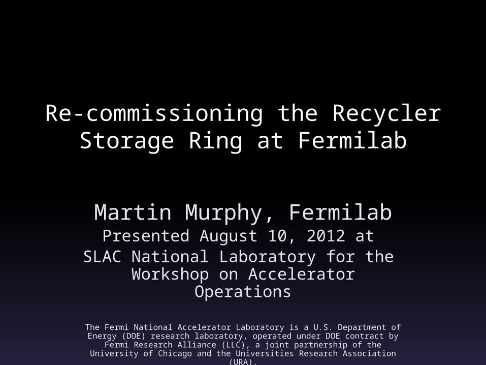
Aerial View of Fermilab

Original Recycler Ring (RR) Design
• Shared tunnel with the Main Injector synchrotron
• Designed to be an 8.8 -GeV antiproton storage ring comprised primarily of permanent magnets 2.5-miles in circumference.
• Powered dipoles, quad, and sextupoles for control over closed orbit, tunes, & chromaticity.

Original RR Design• Employed four 5-KW, 2.5-MHz RF
cavities for beam capture/manipulation.
• Employed stochastic and electron cooling systems for longitudinal and transverse cooling.
• Beam tube vacuum ~10-11 Torr maintained by ion pumps and titanium sublimation pumps.
Original RR Design
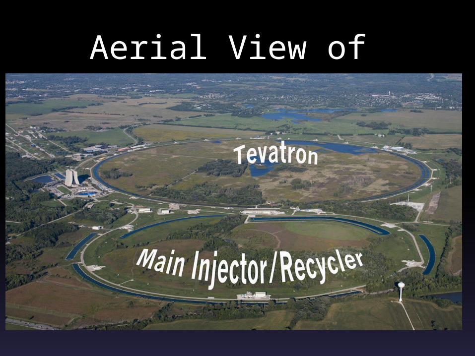
• Two beam transfer lines comprised of permanent and powered bend/focus elements.
• BPMs resonant at 2.5-MHz.• Transverse and longitudinal beam
damper systems were employed.

With the end of Tevatron collider physics came the end of the RR as an
antiproton storage ring.
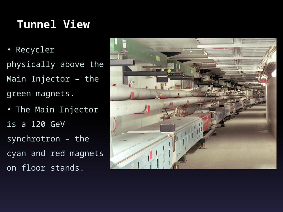
Tunnel View
• Recycler physically
above the Main
Injector – the green
magnets.
• The Main Injector is a
120 GeV synchrotron
– the cyan and red
magnets on floor
stands.

Motivation for Re-Purposing
• NOnA: A high power neutrino
program ~ 750 KW beam power on
target.
• Existing FNAL proton front end limits
operation Main Injector to ~350 KW
due to duty cycle (~8 Hz) limitations.

Motivation for Re-Purposing• Historic
operation of PS & MI used 11 fills from Booster at ~4.3 E12 per fill.
• The MI cycle time was 2.2 seconds.
• 0.75 seconds was spent on proton injection process.
• Incorporating the RR will allow us to raise beam power on target without increasing the intensity of the PS.

Motivation for Re-Purposing
Mai
n In
ject
orRe
cycl
er
• 120-GeV ramp time ~1.3 seconds
• PS duty cycle of 66 mS (15 Hz)
• 12 proton batches from PS injected into MI takes 0.8 sec.
• Almost double MI duty cycle by using RR for proton injection!
• Beam power -> 350 KW to 700 KW.

Decommissioning RR• Electron and stochastic cooling
systems.• Existing transfer lines removed.• High & Low Level RF systems• Diagnostics: BPMs, BLMs, schottky
pick-ups, ect.• Timing scenarios, beam
synchronization, etc.

Decommissioning RR Electron Cooling
• 5 MeV electrons were injected parallel to the stored pbars.
• Pbars exchanged momentum with much cooler electrons, thus cooling the stash.
• Electrons were returned from the RR to the Pelletron, where they were decelerated and collected.

Decommissioning e-CoolBudgets are tight, so…

The last slide was joke. The Pelletron is not for sale on eBay.

Scope of Shutdown Jobs
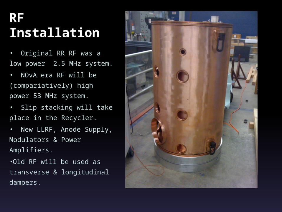
Completely New RF Installation• Original RR RF was a low
power 2.5 MHz system.
• NOvA era RF will be
(compariatively) high power
53 MHz system.
• Slip stacking will take place
in the Recycler.
• New LLRF, Anode Supply,
Modulators & Power
Amplifiers.
•Old RF will be used as
transverse & longitudinal
dampers.

Converting RR to Proton Storage Ring• New 8-GeV injection line directly
from the Booster.• Three new 53 MHz RF cavities
(original 2.5 MHz RF cavities will serve as longitudinal and transverse dampers).
• New extraction line to Main Injector.• Injection gap clearing kickers (reduce
losses during injection process).

Converting RR to Proton Storage Ring
• New BPM system: Dual 2.5 & 53 MHz boards to support NOnA and Muon Rings operation (g Minus 2 & m-to-e experiments)
• New beam loss measurement process – how do you differentiate loss from MI & RR?
• New Diagnostics: e.g. Ion Profile Monitors
• New time-line paradigm.

New Service BuildingsMI14 – Injection Kicker
Power Supplies & controls
•
MI39 – Gap Clearing
Kickers

3D Draft of New Injection Line: Booster to RR
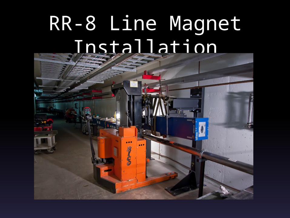
RR-8 Line Magnet Installation
Impact on Operations• Some operators on loan to other
groups during shutdown (e.g. Alignment, Instrumentation, etc.)
• Brand new operating paradigm.• Constant supply of high power
protons in MI/RR tunnel -> Beam Envelope & radiation safety (shielding!) considerations.
• Many new applications to be written and learned.

Operator involvement
• Writing new console applications.
• Building new utilities – e.g. Electronic
Logbook.
• Maintain skeleton crews during shutdown.
• Tunnel work –
Removal of obsolete instrumentation
Alignment
Terminating new BPM cables

Other Upgrades of Note• New H- ion source!• Renovation the Booster RF cavities
and modulators.• Two additional RF cavities will be
installed in the Main Injector.• New targets for neutrino production.• New slow extraction septa for
switchyard programs.

Summary• Fermilab’s mission has shifted from the
“Energy Frontier” to the “Intensity
Frontier.”
• We need to double power onto the NuMI
target without significantly increasing the
Proton Source output.
• To meet this goal we’re converting the
Recycler to a proton storage ring and
upgrading many other systems.
Thanks for your attention.
• Questions?
The Fermi National Accelerator Laboratory is a U.S. Department of Energy (DOE)research laboratory,
operated under DOE contract by Fermi Research Alliance(LLC), a joint partnership of the University
of Chicago and the Universities Research Association (URA).