RE 29403 Type 2WFCE - dc-us.resource.bosch.com · Proportional directional valve 2FCE 5/28 RE...
28
RE 29403, edition: 2017-01, Bosch Rexroth AG Proportional directional valve, pilot-operated, with integrated electronics (OBE) Features ▶ 2/2-way version ▶ Cartridge valve ▶ Robust – Pressure resistance up to 420 bar – High vibration resistance (acc. to DIN EN60068-2) – Ambient temperature up to +60 °C ▶ Precise – High response sensitivity and little hysteresis ▶ Reliable – High-quality and proven design ▶ Normalized – Installation dimensions according to ISO 7368 ▶ Flexible – In connection with a pressure compensator pressure- compensated flow control possible ▶ Safe – Fail-safe position of the main stage in case of power failure, cable break or disconnected enable Contents Features 1 Ordering code 2 Function, section, symbol 3 Technical data 4, 5 Integrated electronics (OBE) 6 Block diagram/controller function block 6; 7 Electrical connections and assignment 8 Characteristic curves 9 … 18 Dimensions 19 … 25 Accessories 26, 27 Further information 28 ▶ Size 16 … 50 ▶ Component series 1X ▶ Maximum operating pressure 420 bar ▶ Maximum flow 1500 l/min (∆p = 5 bar) RE 29403 Edition: 2017-01 Replaces: 2016-02 H8069 Type 2WFCE
-
Upload
truongthuan -
Category
Documents
-
view
214 -
download
0
Transcript of RE 29403 Type 2WFCE - dc-us.resource.bosch.com · Proportional directional valve 2FCE 5/28 RE...

RE 29403 edition 2017-01 Bosch Rexroth AG
Proportional directional valve pilot-operated with integrated electronics (OBE)
Features
22-way version Cartridge valve Robust
ndash Pressure resistance up to 420 bar ndash High vibration resistance (acc to DIN EN60068-2) ndash Ambient temperature up to +60 degC
Precise ndash High response sensitivity and little hysteresis
Reliable ndash High-quality and proven design
Normalized ndash Installation dimensions according to ISO 7368
Flexible ndash In connection with a pressure compensator pressure-compensated flow control possible
Safe ndash Fail-safe position of the main stage in case of power failure cable break or disconnected enable
Contents
Features 1Ordering code 2Function section symbol 3Technical data 4 5Integrated electronics (OBE) 6Block diagramcontroller function block 6 7Electrical connections and assignment 8Characteristic curves 9 hellip 18Dimensions 19 hellip 25Accessories 26 27Further information 28
Size 16 hellip 50 Component series 1X Maximum operating pressure 420 bar Maximum flow 1500 lmin (∆p = 5 bar)
RE 29403thinspEdition 2017-01Replaces 2016-02
H8069
Type 2WFCE
Inhalt
Features 1Contents 1Ordering code 2Function section symbol 3Technical data (For applications outside these parameters please consult us) 4Technical data (For applications outside these parameters please consult us) 5Integrated electronics (OBE) 6Block diagramcontroller function block Version 6 + PE 6Block diagramcontroller function block Version 11 + PE 7Block diagramcontroller function block Version 11 + PE
7Electrical connections and assignment 8Characteristic curves Size 16 (measured with HLP46 ϑOil = 40 plusmn5 degC) 9Characteristic curves Size 16 (measured with HLP46 ϑOil = 40 plusmn5 degC) 10Characteristic curves Size 25 (measured with HLP46 ϑOil = 40 plusmn5 degC) 11Characteristic curves Size 25 (measured with HLP46 ϑOil = 40 plusmn5 degC) 12Characteristic curves Size 32 (measured with HLP46 ϑOil = 40 plusmn5 degC) 13Characteristic curves Size 32 (measured with HLP46 ϑOil = 40 plusmn5 degC) 14Characteristic curves Size 40 (measured with HLP46 ϑOil = 40 plusmn5 degC) 15Characteristic curves Size 40 (measured with HLP46 ϑOil = 40 plusmn5 degC) 16Characteristic curves Size 50 (measured with HLP46 ϑOil = 40 plusmn5 degC) 17Characteristic curves Size 50 (measured with HLP46 ϑOil = 40 plusmn5 degC) 18Dimensions Size 16 (dimensions in mm) 19Dimensions Size 25 (dimensions in mm) 20Dimensions Size 32 (dimensions in mm) 21Dimensions Size 40 (dimensions in mm) 22Dimensions Size 50 (dimensions in mm) 23Installation bore (dimensions in mm) 24Dimensions 25Accessories (separate order) 26Accessories (separate order) 27Further information 28
228 2WFCE | Proportional directional valve
Bosch Rexroth AG RE 29403 edition 2017-01
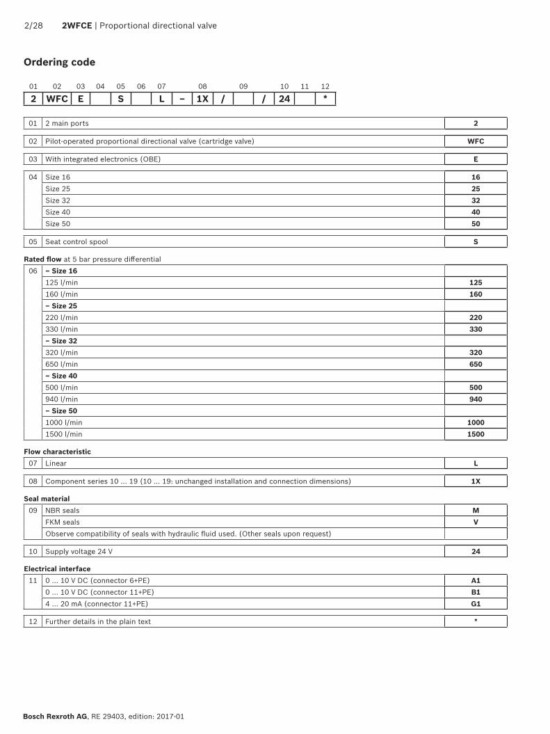
Ordering code
01 2 main ports 2
02 Pilot-operated proportional directional valve (cartridge valve) WFC
03 With integrated electronics (OBE) E
04 Size 16 16Size 25 25Size 32 32Size 40 40Size 50 50
05 Seat control spool S
Rated flow at 5 bar pressure differential06 ndash Size 16
125 lmin 125160 lmin 160ndash Size 25220 lmin 220330 lmin 330ndash Size 32320 lmin 320650 lmin 650ndash Size 40500 lmin 500940 lmin 940ndash Size 501000 lmin 10001500 lmin 1500
Flow characteristic07 Linear L
08 Component series 10 hellip 19 (10 hellip 19 unchanged installation and connection dimensions) 1X
Seal material09 NBR seals M
FKM seals VObserve compatibility of seals with hydraulic fluid used (Other seals upon request)
10 Supply voltage 24 V 24
Electrical interface11 0 10 V DC (connector 6+PE) A1
0 10 V DC (connector 11+PE) B14 20 mA (connector 11+PE) G1
12 Further details in the plain text
01 02 03 04 05 06 07 08 09 10 11 12
2 WFC E S L ndash 1X 24
4 3
1 2
A
B
B
AX Y
Proportional directional valve | 2WFCE 328
RE 29403 edition 2017-01 Bosch Rexroth AG
Set-upThe pilot-operated proportional directional valve type 2WFCE basically consists of
Cover (1) Main stage (2) Pilot control valve with proportional solenoid (3) Integrated electronics with position transducer and
analog interface (4)
Function section symbol
The integrated electronics (OBE) compare the specified command value to the position actual value of the control spool of the main stage (2) In case of control deviations the solenoid of the pilot control valve (3) is activated In this way the control spool is adjusted Depending on the control deviation the control chamber of the main stage (2) is either pressurized with pilot oil (the main stage closes) or unloaded (the main stage opens) Stroke and orifice cross-section are controlled proportionally to the command value until the control deviation is remedied For proper function the following has to be observed
Direction of flow A rarr B (X connected to A) Direction of flow B rarr A (X connected to B)
Failure of supply voltage If the minimum supply voltage fails or is fallen below the enable is disconnected (only interfaces B1 and G1) and in case of a cable break of the solenoid conductor the integrated electronics (OBE) will de-energize the solenoid of the pilot control valve (3) The control spool of the main stage (2) moves securely to its seat using the pressure available at port X and the force of the main stage spring and blocks the flow between A and B
Flow control functionIn connection with a pressure compensator the pilot-operated proportional directional valve can be used for the pressure-compensated control of a flow
Notices Representation according to DIN ISO 1219-1
Direction of flow ndash A rarr B (X connected to A) ndash B rarr A (X connected to B)
Symbol
428 2WFCE | Proportional directional valve
Bosch Rexroth AG RE 29403 edition 2017-01
Technical data (For applications outside these parameters please consult us)
generalSize NG 16 25 32 40 50Weight kg 35 46 58 79 105Installation position AnyAmbient temperature range degC ndash30 +60 (NBR seals)
ndash20 +60 (FKM seals)Maximum storage time Years 1 (if the storage conditions are observed refer to the operating
instructions 07600-B)Vibration resistance Sine test according to DIN EN 60068-2-6 10 2000 Hz maximum of 10 g 10 cycles 3 axes
Noise test according to DIN EN 60068-2-64 20 hellip 2000 Hz 10 gRMS 30 g peak 30 min 3 axes Transport shock according to DIN EN 60068-2-27 15 g 11 ms 3 axes
Maximum relative humidity (no condensation) 95Maximum surface temperature degC 150MTTFd value according to EN ISO 13849 Years 75 (for further details see data sheet 08012)
hydraulicMaximum operating pressure Port A B bar 420Minimum operating pressure Port A (A rarr B) bar 12
Port B (B rarr A) bar 20Maximum pilot pressure Port X bar 420Maximum return flow pressure Port Y bar 100Rated flow (∆p = 5 bar) 1)) lmin 125 160 220 330 320 650 500 940 1000 1500Maximum pilot flow 2) lmin 3 5 7 9 9Leakage flow Pilot control valve (at 100 bar) cm3min lt 150 lt 200 lt 200 lt 400 lt 400
Main stage ndash Interface A1 (0 V) cm3min A rarr B and B rarr A blocked in a leakage-free manner (valve in seat position) ndash Interface B1 (0 V) cm3min Depending on ∆p see characteristic curves on page 9 hellip18 ndash Interface G1 (4 mA) cm3min Depending on ∆p see characteristic curves on page 9 hellip18 ndash Interface B1 G1 3 4 5) cm3min A rarr B and B rarr A blocked in a leakage-free manner (valve in seat position)
Pilot volume Main stage 2) cm3 1 27 64 126 245Direction of flow Internal pilot oil supply
ndash A rarr B A connected to X ndash B rarr A B connected to X
External pilot oil supply ndash A rarr B Pressure in X ge pressure in A ndash B rarr A Pressure in X ge pressure in B
Hydraulic fluid See table page 5Viscosity range Recommended mm2s 20 hellip 100
Maximum admissible mm2s 15 hellip 380Hydraulic fluid temperature range (flown-through) degC -20 hellip +60Maximum admissible degree of contamination of the hydraulic fluid cleanliness class according to ISO 4406 (c)
Class 181613 5)
1) Flow for deviating ∆p
qx = qV nom x ∆px5
2) Stepped input signal (seat position at 100 pilot pressure 100 bar)
3) Pin 3 0 V4) Internal pilot oil supply Observe leakage flow A rarr X or B rarr X via
pilot control valve to Y (see technical data leakage flow ndash pilot control valve)
5) External pilot oil supply Leakage flow from A or B via the pilot control valve is avoided a minimum leakage flow X rarr B is however possible
6) The cleanliness classes specified for the components must be adhered to in hydraulic systems Effective filtration prevents faults and simultaneously increases the life cycle of the components
For the selection of the filters see wwwboschrexrothcomfilter
Proportional directional valve | 2WFCE 528
RE 29403 edition 2017-01 Bosch Rexroth AG
Technical data (For applications outside these parameters please consult us)
Hydraulic fluid Classification Suitable sealing materials
Standards Data sheet
Mineral oils HL HLP NBR FKM DIN 51524 90220Flame-resistant Water-free HFDU based on glycol FKM ISO 12922 90222
Important information on hydraulic fluids For further information and data on the use of other hydraulic fluids please refer to the data sheets above or contact us
There may be limitations regarding the technical valve data (temperature pressure range life cycle maintenance intervals etc)
The ignition temperature of the hydraulic fluid used must be 50 K higher than the maximum surface temperature
static dynamicHysteresis lt 02Range of inversion lt 01Response sensitivity lt 01Manufacturing tolerance qVmax le 10Temperature drift 40 K lt 1Zero compensation Ex plant plusmn1
electrical integrated electronics (OBE)Relative duty cycle 100 (continuous operation)Protection class according to EN 60529 IP 65 with mating connector mounted and lockedSupply voltage Nominal voltage VDC 24
Lower limit value VDC 18 Upper limit value VDC 36 Maximum admissible residual ripple
Vss 25 (Comply with absolute supply voltage limit value)
Current consumption Maximum A 2
Impulse current A 3
Maximum power consumption W 50
Functional earth and screening See connector pin assignment (CE-compliant installation) page 8Required fuse protection external A 25 time-lagAdjustment Calibrated in the plant see characteristic curves page 9 18Conformity CE according to EMC Directive 2004108EC
tested according to EN 61000-6-2 and EN 61000-6-3
628 2WFCE | Proportional directional valve
Bosch Rexroth AG RE 29403 edition 2017-01
Integrated electronics (OBE)
Function1 Switch-on procedureFault behaviorAfter applying the supply voltage of 24 V the electronics are ready for operation provided that the following conditions are met
Supply voltage UB gt 18 V DC Connection to solenoid not interrupted Command value line not interrupted and command
value gt 27 mA (interface G1 only)If one of the conditions is not met the controllers and the output stage will be blocked and the ready for operation signal to pin 11 (interface B1 and G1 only) will be set to 0 V
2 Actual value output signals Electrical interfaces A1 (pin F) and B1 (pin 6)
ndash A1 035 V hellip +10 V corresponds to 0 hellip 100 valve opening orifice spool in seat position if actual value lt -25 V
ndash B1 0 V hellip +10 V corresponds to 0 hellip 100 valve opening orifice spool in seat position if actual value lt -15 V
Electrical interface G1 (pin 6) ndash 4 mA hellip +20 mA corresponds to 0 hellip 100 valve opening orifice spool in seat position if actual value lt 27 mA
Block diagramcontroller function block Version 6 + PE
DE UI
U X
Y
UI
VS
FC
AB
UIU
DC
DC
+15 V 10 mAndashVref = -33V
M0+(75-8) V 50 mA
+33V 10mA
ndash (75-8) V 50 mA
amp
24 V0 V
Command value
Short-circuit of solenoid
Cable break of solenoid
Amplifier differential
Position transducer
Protection circuit
Protection circuit
Protection circuit
Actual value
output Controller
Demodulator
Sinus oscillator
Output stage
Command value
enable
Actual value
Command value reference
Actual value reference
Supply voltage
Notices Electrical interface A1
ndash in opening direction Valve active if command value ge 05 V ndash in closing direction Valve deactivated if command value le 03 V (on seat)
Electrical interfaces B1 and G1 ndash in opening direction Valve active if enable pin 3 is set command value gt -1 V (B1) or gt 2 mA (G1)
ndash in closing direction Valve deactivated if enable pin 3 is not set command value lt -1 V (B1) or lt 2 mA (G1) (on seat)
Command value B1 and G1 A1
Without enable ndash
0 V
gt0 V hellip 035 V
gt035 V hellip lt05 V
gt05 V
Inverse-polarity
protection
Proportional directional valve | 2WFCE 728
RE 29403 edition 2017-01 Bosch Rexroth AG
Block diagramcontroller function block Version 11 + PE
45
11
UIU
UI
VS
67
1
1098
2
UIU
DC
DC
+15 V 10 mAndashVref = -33V
M0+(75-8) V 50 mA
+33V 10mA
ndash (75-8) V 50 mA
amp
24 V0 V
3
Command value
Enable input
Short-circuit of solenoid
Cable break of solenoid
Amplifier differential
Position transducer
Protection circuit
Protection circuit
Protection circuit
Inverse-polarity
protection
Actual value
output Controller
Demodulator
Sinus oscillator
Output stage
Cable break (G1)
Enable
Actual value
Ready for operation
free
free
free
Command value reference
Actual value reference
Supply voltage
Notices Electrical interface A1
ndash in opening direction Valve active if command value ge 05 V ndash in closing direction Valve deactivated if command value le 03 V (on seat)
Electrical interfaces B1 and G1 ndash in opening direction Valve active if enable pin 3 is set command value gt -1 V (B1) or gt 2 mA (G1)
ndash in closing direction Valve deactivated if enable pin 3 is not set command value lt -1 V (B1) or lt 2 mA (G1) (on seat)
Command value B1 and G1 A1
Without enable ndash
0 V
gt0 V hellip 035 V
gt035 V hellip lt05 V
gt05 V
828 2WFCE | Proportional directional valve
Bosch Rexroth AG RE 29403 edition 2017-01
Electrical connections and assignment
Pin Core marking 1)
Interface assignment6 + PE 11 + PE A1 (6 + PE) B1(11 + PE) G1(11 + PE)
A 1 1 Supply voltage 24 VDCB 2 2 GNDC 3 3 Reference potential actual value Enable input 24 VDC (high ge 12 V low le5 V)D 4 4 Command value 0 hellip 10 V Command value 4 hellip20 mAE 5 5 Reference potential command value F 6 6 Actual value 0 hellip 10 V Actual value 4 hellip 20 mA
7 7 Reference potential actual value 8 8 ndash9 9 ndash10 10 ndash11 11 ndash Switching output 24 V ndash fault-free operation (supply
voltage -1 V)fault (0 V) or power circuit signal) maximum 50 mA
PE PE green-yellow Functional earth (directly connected to the valve housing)
A
C
BPE
F
ED
F
1
2
3
4 56
7
8PE
910
11
Connector pin assignment
1) Core marking of the connection lines for mating connector with cable set see accessories page 26 and 27
00
50
100
150
200
250
300
350
400
1 2 3 4 5 6 7 8 9 10
1
2
3
00
50
100
150
200
250
300
350
400
1 2 3 4 5 6 7 8 9 10
1
2
3
Proportional directional valve | 2WFCE 928
RE 29403 edition 2017-01 Bosch Rexroth AG
Characteristic curves Size 16 (measured with HLP46 ϑOil = 40 plusmn5 degC)
Flowsignal function
Version 125 (A rarr B B rarr A)
Version 160 (A rarr B B rarr A)
Command value in V rarr
Command value in V rarr
Flow
in l
min
rarrFl
ow in
lm
in rarr
1 Pressure differential 20 bar2 Pressure differential 10 bar3 Pressure differential 5 bar
00
2
4
6
8
50 100 150 200 250 300 350 400 420
0 40 80 120 160 200 0 40 80 120 160 2000102030405060708090
100
1 10 20 30 40 50 60 80 100-40
-30
-60-90
-120
-150
-180-210
-240-270
-35-30-25
-20
-15-10
-5
05
1028 2WFCE | Proportional directional valve
Bosch Rexroth AG RE 29403 edition 2017-01
Characteristic curves Size 16 (measured with HLP46 ϑOil = 40 plusmn5 degC)
Leakage as a function of the pressure differential (Command value A1 ndash 05 V B1 ndash 0 V G1 ndash 4 mA)
Transition function with stepped electric input signals (pA = 100 bar)
Frequency response (pA= 100 bar)
Pressure differential in bar rarr
Time in ms rarr
Frequency in Hz rarr
Flow
in l
min
rarrSt
roke
in
rarrAm
plitu
de r
atio
in d
B rarr
Phas
e an
gle
in deg
rarr
Scatter range
Step responses in
5 ndash 100 ndash 510 ndash 90 ndash 1025 ndash 75 ndash 25
Signals in
5 ndash 100 ndash 510 ndash 90 ndash 1025 ndash 75 ndash 25
00
50
100
150
200
250
300
350
400
1 2 3 4 5 6 7 8 9 10
1
2
3
00
100
200
300
400
500
600
700
800
1 2 3 4 5 6 7 8 9 10
1
2
3
Proportional directional valve | 2WFCE 1128
RE 29403 edition 2017-01 Bosch Rexroth AG
Characteristic curves Size 25 (measured with HLP46 ϑOil = 40 plusmn5 degC)
Flowsignal function
Version 220 (A rarr B B rarr A)
Version 330 (A rarr B B rarr A)
Command value in V rarr
Command value in V rarr
Flow
in l
min
rarrFl
ow in
lm
in rarr
1 Pressure differential 20 bar2 Pressure differential 10 bar3 Pressure differential 5 bar
0 40 80 120 160 200 0 40 80 120 160 2000102030405060708090
100
00
246
18
8
1012
1416
50 100 150 200 250 300 350 400 420
1 10 20 30 40 50 60 80 100-40
-35-30-25
-20
-15-10
-5
05
-30
-60-90
-120
-150
-180-210
-240-270
1228 2WFCE | Proportional directional valve
Bosch Rexroth AG RE 29403 edition 2017-01
Characteristic curves Size 25 (measured with HLP46 ϑOil = 40 plusmn5 degC)
Leakage as a function of the pressure differential (Command value A1 ndash 05 V B1 ndash 0 V G1 ndash 4 mA)
Transition function with stepped electric input signals (pA = 100 bar)
Frequency response (pA= 100 bar)
Pressure differential in bar rarr
Flow
in l
min
rarrSt
roke
in
rarr
Scatter range
Step responses in
5 ndash 100 ndash 510 ndash 90 ndash 1025 ndash 75 ndash 25
Signals in
5 ndash 100 ndash 510 ndash 90 ndash 1025 ndash 75 ndash 25
Frequency in Hz rarr
Ampl
itude
rat
io in
dB
rarr
Phas
e an
gle
in deg
rarr
Time in ms rarr
00
100
200
300
700
400
500
600
1 2 3 4 5 6 7 8 9 10
1
2
3
00
200
400
600
800
1000
1200
1400
1 2 3 4 5 6 7 8 9 10
1
2
3
Proportional directional valve | 2WFCE 1328
RE 29403 edition 2017-01 Bosch Rexroth AG
Characteristic curves Size 32 (measured with HLP46 ϑOil = 40 plusmn5 degC)
Flowsignal function
Version 320 (A rarr B B rarr A)
Version 650 (A rarr B B rarr A)
Command value in V rarr
Command value in V rarr
Flow
in l
min
rarrFl
ow in
lm
in rarr
1 Pressure differential 20 bar2 Pressure differential 10 bar3 Pressure differential 5 bar
0 100 200 300 100 200 300400 0 4000102030405060708090
100
00
246
18
8
1012
1416
50 100 150 200 250 300 350 400 420
1 10 20 30 40 50 60 80 100-40
-35-30-25
-20
-15-10
-5
05
-30
-60-90
-120
-150
-180-210
-240-270
1428 2WFCE | Proportional directional valve
Bosch Rexroth AG RE 29403 edition 2017-01
Characteristic curves Size 32 (measured with HLP46 ϑOil = 40 plusmn5 degC)
Leakage as a function of the pressure differential (Command value A1 ndash 05 V B1 ndash 0 V G1 ndash 4 mA)
Transition function with stepped electric input signals (pA = 100 bar)
Frequency response (pA= 100 bar)
Pressure differential in bar rarr
Flow
in l
min
rarrSt
roke
in
rarr
Scatter range
Step responses in
5 ndash 100 ndash 510 ndash 90 ndash 1025 ndash 75 ndash 25
Signals in
5 ndash 100 ndash 510 ndash 90 ndash 1025 ndash 75 ndash 25
Frequency in Hz rarr
Ampl
itude
rat
io in
dB
rarr
Phas
e an
gle
in deg
rarr
Time in ms rarr
00
200
400
600
1400
800
1200
1000
1 2 3 4 5 6 7 8 9 10
1
2
3
00
200
400
600
800
10001200
1400
1600
1800
2200
2000
1 2 3 4 5 6 7 8 9 10
1
2
3
Proportional directional valve | 2WFCE 1528
RE 29403 edition 2017-01 Bosch Rexroth AG
Characteristic curves Size 40 (measured with HLP46 ϑOil = 40 plusmn5 degC)
Flowsignal function
Version 500 (A rarr B B rarr A)
Version 940 (A rarr B B rarr A)
Command value in V rarr
Command value in V rarr
Flow
in l
min
rarrFl
ow in
lm
in rarr
1 Pressure differential 20 bar2 Pressure differential 10 bar3 Pressure differential 5 bar
0 100 200 300 100 200 300400 0 4000102030405060708090
100
00
246
18
8
1012
1416
50 100 150 200 250 300 350 400 420
1 10 20 30 40 50 60 80 100-40
-35-30-25
-20
-15-10
-5
05
-30
-60-90
-120
-150
-180-210
-240-270
1628 2WFCE | Proportional directional valve
Bosch Rexroth AG RE 29403 edition 2017-01
Characteristic curves Size 40 (measured with HLP46 ϑOil = 40 plusmn5 degC)
Leakage as a function of the pressure differential (Command value A1 ndash 05 V B1 ndash 0 V G1 ndash 4 mA)
Transition function with stepped electric input signals (pA = 100 bar)
Frequency response (pA= 100 bar)
Pressure differential in bar rarr
Flow
in l
min
rarrSt
roke
in
rarr
Scatter range
Step responses in
5 ndash 100 ndash 510 ndash 90 ndash 1025 ndash 75 ndash 25
Signals in
5 ndash 100 ndash 510 ndash 90 ndash 1025 ndash 75 ndash 25
Frequency in Hz rarr
Ampl
itude
rat
io in
dB
rarr
Phas
e an
gle
in deg
rarr
Time in ms rarr
00
200
400
600
800
1000
1200
1400
1600
1800
2000
1 2 3 4 5 6 7 8 9 10
1
2
3
00
200
400
600
800
1000
1200
1400
1600
1800
2000
1 2 3 4 5 6 7 8 9 10
12
3
Proportional directional valve | 2WFCE 1728
RE 29403 edition 2017-01 Bosch Rexroth AG
Characteristic curves Size 50 (measured with HLP46 ϑOil = 40 plusmn5 degC)
Flowsignal function
Version 1000 (A rarr B B rarr A)
Version 1500 (A rarr B B rarr A)
Command value in V rarr
Command value in V rarr
Flow
in l
min
rarrFl
ow in
lm
in rarr
1 Pressure differential 20 bar2 Pressure differential 10 bar3 Pressure differential 5 bar
0 100 200 300 100 200 300400 0 4000102030405060708090
100
00
246
20
81012141618
50 100 150 200 250 300 350 400 420
1 10 20 30 40 50 60 80 100-40
-35-30-25
-20
-15-10
-5
05
-30
-60-90
-120
-150
-180-210
-240-270
1828 2WFCE | Proportional directional valve
Bosch Rexroth AG RE 29403 edition 2017-01
Characteristic curves Size 50 (measured with HLP46 ϑOil = 40 plusmn5 degC)
Leakage as a function of the pressure differential (Command value A1 ndash 05 V B1 ndash 0 V G1 ndash 4 mA)
Transition function with stepped electric input signals (pA = 100 bar)
Frequency response (pA= 100 bar)
Pressure differential in bar rarr
Flow
in l
min
rarrSt
roke
in
rarr
Scatter range
Step responses in
5 ndash 100 ndash 510 ndash 90 ndash 1025 ndash 75 ndash 25
Signals in
5 ndash 100 ndash 510 ndash 90 ndash 1025 ndash 75 ndash 25
Frequency in Hz rarr
Ampl
itude
rat
io in
dB
rarr
Phas
e an
gle
in deg
rarr
Time in ms rarr
Rzmax 4
001100
4
5
3 5
1
2
215
95
286
15
83175
12
42Oslash25g6Oslash32e9
32515 65
47
5056
295
Proportional directional valve | 2WFCE 1928
RE 29403 edition 2017-01 Bosch Rexroth AG
Dimensions Size 16 (dimensions in mm)
NoticeThe dimensions are nominal dimensions which are subject to tolerances
Item explanations and valve mounting screws see page 25
Required surface quality of the valve contact surface
Rzmax 4
001100
4
5
3 5
1
2
231
95
302
15
175
12
5072
39
42Oslash34g6Oslash45e9
425
15
93
8547
2028 2WFCE | Proportional directional valve
Bosch Rexroth AG RE 29403 edition 2017-01
Dimensions Size 25 (dimensions in mm)
NoticeThe dimensions are nominal dimensions which are subject to tolerances
Item explanations and valve mounting screws see page 25
Required surface quality of the valve contact surface
4
5
3 5
1
2
244
50
95
85
35
315
15
42Oslash45g6Oslash60e9
50
15
100175
12
100
Rzmax 4
001100
Proportional directional valve | 2WFCE 2128
RE 29403 edition 2017-01 Bosch Rexroth AG
Dimensions Size 32 (dimensions in mm)
NoticeThe dimensions are nominal dimensions which are subject to tolerances
Item explanations and valve mounting screws see page 25
Required surface quality of the valve contact surface
Rzmax 4
001100
4
5
3 5
264
95
335
15
12
1
2
5010
5
40
22
Oslash55g6Oslash75e9
625
15
125 45190
125
2228 2WFCE | Proportional directional valve
Bosch Rexroth AG RE 29403 edition 2017-01
Dimensions Size 40 (dimensions in mm)
NoticeThe dimensions are nominal dimensions which are subject to tolerances
Item explanations and valve mounting screws see page 25
Required surface quality of the valve contact surface
Rzmax 4
001100
4
5
3 5
281
95
352
15
12
1
Oslash68g6Oslash90e9
70140 38190
140
5012
2
32
47
2
Proportional directional valve | 2WFCE 2328
RE 29403 edition 2017-01 Bosch Rexroth AG
Dimensions Size 50 (dimensions in mm)
NoticeThe dimensions are nominal dimensions which are subject to tolerances
Item explanations and valve mounting screws see page 25
Required surface quality of the valve contact surface
Rzmax 4x =
Rzmax 8y =
Rz 10z =
OslashD3
H9
H2+0
1
H8H7H3
+01
H6H5
15deg
OslashD2OslashD4
H1
15deg
OslashD1
A
B
9
9 11 10 12
L1
L4plusmn0
2
L6plusmn02
X YL7plusmn0
2
bdquoAldquo
L2L3
L4plusmn02
L5plusmn02 L5plusmn02
bdquoAldquo
8 7
6
H4
D5
H10
D7H13
OslashD6
OslashD6
y
y
z
01 A y 001 100A
Oslash003 A
2428 2WFCE | Proportional directional valve
Bosch Rexroth AG RE 29403 edition 2017-01
Installation bore (dimensions in mm)
Installation dimensions according to DIN ISO 7368 NG 16 25 32 40 50OslashD1H7 32 45 60 75 90OslashD2 16 25 32 40 50OslashD3 16 25 32 40 50max OslashD3 25 32 40 50 63OslashD4H7 25 34 45 55 68D5 M8 M12 M16 M20 M20max OslashD6 4 6 8 8 10OslashD7H13 4 6 6 6 8H1 34 44 52 64 72H1 1) 295 405 48 59 655H2 56 72 85 105 122H3 43 58 70 87 100H4 20 25 35 45 45H5 11 12 13 15 17H6 2 25 25 3 3H7 20 30 30 30 35H8 2 25 25 3 4min H9 2) 05 1 15 25 25min H10 8 8 8 8 8L1 65 85 100 125 140L2 83 93 100 125 140L3 325 425 50 625 70L4 46 58 70 85 100L5 25 33 41 50 58L6 105 16 17 23 30L7 23 29 35 425 50
NG Installation dimensions according to DIN ISO 736816 ISO 7368-BA-06-2-A25 ISO 7368-BB-08-2-A32 ISO 7368-BC-09-2-A40 ISO 7368-BD-10-2-A50 ISO 7368-BE-11-2-A
1) Bore center at OslashD3 max2) Control dimension
Tolerances according to General tolerances ISO 2768-mK
Item explanations and valve mounting screws see page 25
Section A ndash A
Proportional directional valve | 2WFCE 2528
RE 29403 edition 2017-01 Bosch Rexroth AG
Dimensions
1 Cover2 Main stage3 Pilot control valve with proportional solenoid4 Integrated electronics with position transducer and analog
interface5 Space required to remove the mating connectors6 Port X7 Port Y8 Locating hole for locking pin9 Depth of fit
10 Control dimension11 Port B may be at any position around the central axis of port
A However it must be observed that the mounting bores and the control bores are not damaged
12 If a different diameter is used for port B than indicated in the dimensional table the distance from the cover support surface to the bore center must be calculated
Valve mounting screws (separate order)Size Hexagon socket head cap screws Material number16 4 hexagon socket head cap screws ISO 4762 - M8 x 30 - 109 - N67F 821 70
(galvanized according to Bosch standard N67F821 70) Tightening torque MA = 35 plusmn5 Nm
2910151246
25 4 hexagon socket head cap screws ISO 4762 - M12 x 40 - 109 - N67F 821 70 (galvanized according to Bosch standard N67F821 70) Tightening torque MA = 105 plusmn15 Nm
2910151346
32 4 hexagon socket head cap screws ISO 4762 - M16 x 50 - 109 - N67F 821 70 (galvanized according to Bosch standard N67F821 70) Tightening torque MA = 265 plusmn25 Nm
2910151442
40 4 hexagon socket head cap screws ISO 4762 - M20 x 60 - 109 - N67F 821 70 (galvanized according to Bosch standard N67F821 70) Tightening torque MA = 500 plusmn50 Nm
2910151526
50
2628 2WFCE | Proportional directional valve
Bosch Rexroth AG RE 29403 edition 2017-01
Connector connection version 6 + PE Mating connector Version Material numberRound connector according to EN 175201-804 (7-pole plastic variant)
Mating connector (assembly kit) for a cable diameter of 65 11 mm
R900021267
Mating connector with 3 m cable 7 x 075 mm2 assembled R901420483Mating connector with 5 m cable 7 x 075 mm2 assembled R901420491Mating connector with 10 m cable 7 x 075 mm2 assembled R901420496
91 Oslash27
AB
CD
E
F
Round connector according to EN 175201-804 (7-pole metal design)
Mating connector (assembly kit) for a cable diameter of 80 135 mm
R900223890
AB
C DE
F
85 Oslash284
Accessories (separate order)
Proportional directional valve | 2WFCE 2728
RE 29403 edition 2017-01 Bosch Rexroth AG
Connector connection version 11 + PE Mating connector Version Material numberMating connector according to DIN EN 175201-804 (12-pole metal design)
Mating connector (assembly kit) for a cable diameter of 12 15 mm
R901268000
Mating connector with 5 m cable 12 x 075 mm2 with cable shield assembled
R901272854
Mating connector with 20 m cable 12 x 075 mm2 with cable shield assembled
R901272852
41~91 Oslash28
SW22
M26 x 15SW
24
1
2
456
7
8911
10 3
Mating connector according to DIN EN 175201-804 (12 pole plastic variant)
Mating connector (assembly kit) R900884671Mating connector with 2 x 5 m cable supply line (3 x 10 mm2) and signal line (10 x 014 mm2) separated with cable shield assembled
R900032356
Mating connector with 2 x 20 m cable supply line (3 x 10 mm2) and signal line (10 x 014 mm2) separated with cable shield assembled
R900860399
1
2
456
7
8911
10 3
33
90
Accessories (separate order)
Bosch Rexroth AG RE 29403 edition 2017-01
2828 2WFCE | Proportional directional valve
Bosch Rexroth AG HydraulicsZum Eisengieszliger 197816 Lohr am Main Germany Phone +49 (0) 93 52thinspthinsp18-0 documentationboschrexrothde wwwboschrexrothde
copy This document as well as the data specifications and other information set forth in it are the exclusive property of Bosch Rexroth AG It may not be reproduced or given to third parties without its consentThe data specified above only serve to describe the product No statements concerning a certain condition or suitability for a certain application can be derived from our information The information given does not release the user from the obligation of own judgment and verification It must be remembered that our products are subject to a natural process of wear and aging
Further information
Hydraulic fluids on mineral oil basis Data sheet 90220 Environmentally compatible hydraulic fluids Data sheet 90221 Flame-resistant water-free hydraulic fluids Data sheet 90222 Flame-resistant hydraulic fluids - containing water (HFAE HFAS HFB HFC) Data sheet 90223 Reliability characteristics according to EN ISO 13849 Data sheet 08012 Hydraulic valves for industrial applications Operating instructions 07600-B Selection of filters wwwboschrexrothcomfilter Information on available spare parts wwwboschrexrothcomspc
- Features
- Contents
- Ordering code
- Function section symbol
- Technical data
- Integrated electronics (OBE)
- Block diagramcontroller function block
- Electrical connections and assignment
- Characteristic curves
- Dimensions
- Installation bore
- Accessories
- Further information
-
228 2WFCE | Proportional directional valve
Bosch Rexroth AG RE 29403 edition 2017-01
Ordering code
01 2 main ports 2
02 Pilot-operated proportional directional valve (cartridge valve) WFC
03 With integrated electronics (OBE) E
04 Size 16 16Size 25 25Size 32 32Size 40 40Size 50 50
05 Seat control spool S
Rated flow at 5 bar pressure differential06 ndash Size 16
125 lmin 125160 lmin 160ndash Size 25220 lmin 220330 lmin 330ndash Size 32320 lmin 320650 lmin 650ndash Size 40500 lmin 500940 lmin 940ndash Size 501000 lmin 10001500 lmin 1500
Flow characteristic07 Linear L
08 Component series 10 hellip 19 (10 hellip 19 unchanged installation and connection dimensions) 1X
Seal material09 NBR seals M
FKM seals VObserve compatibility of seals with hydraulic fluid used (Other seals upon request)
10 Supply voltage 24 V 24
Electrical interface11 0 10 V DC (connector 6+PE) A1
0 10 V DC (connector 11+PE) B14 20 mA (connector 11+PE) G1
12 Further details in the plain text
01 02 03 04 05 06 07 08 09 10 11 12
2 WFC E S L ndash 1X 24
4 3
1 2
A
B
B
AX Y
Proportional directional valve | 2WFCE 328
RE 29403 edition 2017-01 Bosch Rexroth AG
Set-upThe pilot-operated proportional directional valve type 2WFCE basically consists of
Cover (1) Main stage (2) Pilot control valve with proportional solenoid (3) Integrated electronics with position transducer and
analog interface (4)
Function section symbol
The integrated electronics (OBE) compare the specified command value to the position actual value of the control spool of the main stage (2) In case of control deviations the solenoid of the pilot control valve (3) is activated In this way the control spool is adjusted Depending on the control deviation the control chamber of the main stage (2) is either pressurized with pilot oil (the main stage closes) or unloaded (the main stage opens) Stroke and orifice cross-section are controlled proportionally to the command value until the control deviation is remedied For proper function the following has to be observed
Direction of flow A rarr B (X connected to A) Direction of flow B rarr A (X connected to B)
Failure of supply voltage If the minimum supply voltage fails or is fallen below the enable is disconnected (only interfaces B1 and G1) and in case of a cable break of the solenoid conductor the integrated electronics (OBE) will de-energize the solenoid of the pilot control valve (3) The control spool of the main stage (2) moves securely to its seat using the pressure available at port X and the force of the main stage spring and blocks the flow between A and B
Flow control functionIn connection with a pressure compensator the pilot-operated proportional directional valve can be used for the pressure-compensated control of a flow
Notices Representation according to DIN ISO 1219-1
Direction of flow ndash A rarr B (X connected to A) ndash B rarr A (X connected to B)
Symbol
428 2WFCE | Proportional directional valve
Bosch Rexroth AG RE 29403 edition 2017-01
Technical data (For applications outside these parameters please consult us)
generalSize NG 16 25 32 40 50Weight kg 35 46 58 79 105Installation position AnyAmbient temperature range degC ndash30 +60 (NBR seals)
ndash20 +60 (FKM seals)Maximum storage time Years 1 (if the storage conditions are observed refer to the operating
instructions 07600-B)Vibration resistance Sine test according to DIN EN 60068-2-6 10 2000 Hz maximum of 10 g 10 cycles 3 axes
Noise test according to DIN EN 60068-2-64 20 hellip 2000 Hz 10 gRMS 30 g peak 30 min 3 axes Transport shock according to DIN EN 60068-2-27 15 g 11 ms 3 axes
Maximum relative humidity (no condensation) 95Maximum surface temperature degC 150MTTFd value according to EN ISO 13849 Years 75 (for further details see data sheet 08012)
hydraulicMaximum operating pressure Port A B bar 420Minimum operating pressure Port A (A rarr B) bar 12
Port B (B rarr A) bar 20Maximum pilot pressure Port X bar 420Maximum return flow pressure Port Y bar 100Rated flow (∆p = 5 bar) 1)) lmin 125 160 220 330 320 650 500 940 1000 1500Maximum pilot flow 2) lmin 3 5 7 9 9Leakage flow Pilot control valve (at 100 bar) cm3min lt 150 lt 200 lt 200 lt 400 lt 400
Main stage ndash Interface A1 (0 V) cm3min A rarr B and B rarr A blocked in a leakage-free manner (valve in seat position) ndash Interface B1 (0 V) cm3min Depending on ∆p see characteristic curves on page 9 hellip18 ndash Interface G1 (4 mA) cm3min Depending on ∆p see characteristic curves on page 9 hellip18 ndash Interface B1 G1 3 4 5) cm3min A rarr B and B rarr A blocked in a leakage-free manner (valve in seat position)
Pilot volume Main stage 2) cm3 1 27 64 126 245Direction of flow Internal pilot oil supply
ndash A rarr B A connected to X ndash B rarr A B connected to X
External pilot oil supply ndash A rarr B Pressure in X ge pressure in A ndash B rarr A Pressure in X ge pressure in B
Hydraulic fluid See table page 5Viscosity range Recommended mm2s 20 hellip 100
Maximum admissible mm2s 15 hellip 380Hydraulic fluid temperature range (flown-through) degC -20 hellip +60Maximum admissible degree of contamination of the hydraulic fluid cleanliness class according to ISO 4406 (c)
Class 181613 5)
1) Flow for deviating ∆p
qx = qV nom x ∆px5
2) Stepped input signal (seat position at 100 pilot pressure 100 bar)
3) Pin 3 0 V4) Internal pilot oil supply Observe leakage flow A rarr X or B rarr X via
pilot control valve to Y (see technical data leakage flow ndash pilot control valve)
5) External pilot oil supply Leakage flow from A or B via the pilot control valve is avoided a minimum leakage flow X rarr B is however possible
6) The cleanliness classes specified for the components must be adhered to in hydraulic systems Effective filtration prevents faults and simultaneously increases the life cycle of the components
For the selection of the filters see wwwboschrexrothcomfilter
Proportional directional valve | 2WFCE 528
RE 29403 edition 2017-01 Bosch Rexroth AG
Technical data (For applications outside these parameters please consult us)
Hydraulic fluid Classification Suitable sealing materials
Standards Data sheet
Mineral oils HL HLP NBR FKM DIN 51524 90220Flame-resistant Water-free HFDU based on glycol FKM ISO 12922 90222
Important information on hydraulic fluids For further information and data on the use of other hydraulic fluids please refer to the data sheets above or contact us
There may be limitations regarding the technical valve data (temperature pressure range life cycle maintenance intervals etc)
The ignition temperature of the hydraulic fluid used must be 50 K higher than the maximum surface temperature
static dynamicHysteresis lt 02Range of inversion lt 01Response sensitivity lt 01Manufacturing tolerance qVmax le 10Temperature drift 40 K lt 1Zero compensation Ex plant plusmn1
electrical integrated electronics (OBE)Relative duty cycle 100 (continuous operation)Protection class according to EN 60529 IP 65 with mating connector mounted and lockedSupply voltage Nominal voltage VDC 24
Lower limit value VDC 18 Upper limit value VDC 36 Maximum admissible residual ripple
Vss 25 (Comply with absolute supply voltage limit value)
Current consumption Maximum A 2
Impulse current A 3
Maximum power consumption W 50
Functional earth and screening See connector pin assignment (CE-compliant installation) page 8Required fuse protection external A 25 time-lagAdjustment Calibrated in the plant see characteristic curves page 9 18Conformity CE according to EMC Directive 2004108EC
tested according to EN 61000-6-2 and EN 61000-6-3
628 2WFCE | Proportional directional valve
Bosch Rexroth AG RE 29403 edition 2017-01
Integrated electronics (OBE)
Function1 Switch-on procedureFault behaviorAfter applying the supply voltage of 24 V the electronics are ready for operation provided that the following conditions are met
Supply voltage UB gt 18 V DC Connection to solenoid not interrupted Command value line not interrupted and command
value gt 27 mA (interface G1 only)If one of the conditions is not met the controllers and the output stage will be blocked and the ready for operation signal to pin 11 (interface B1 and G1 only) will be set to 0 V
2 Actual value output signals Electrical interfaces A1 (pin F) and B1 (pin 6)
ndash A1 035 V hellip +10 V corresponds to 0 hellip 100 valve opening orifice spool in seat position if actual value lt -25 V
ndash B1 0 V hellip +10 V corresponds to 0 hellip 100 valve opening orifice spool in seat position if actual value lt -15 V
Electrical interface G1 (pin 6) ndash 4 mA hellip +20 mA corresponds to 0 hellip 100 valve opening orifice spool in seat position if actual value lt 27 mA
Block diagramcontroller function block Version 6 + PE
DE UI
U X
Y
UI
VS
FC
AB
UIU
DC
DC
+15 V 10 mAndashVref = -33V
M0+(75-8) V 50 mA
+33V 10mA
ndash (75-8) V 50 mA
amp
24 V0 V
Command value
Short-circuit of solenoid
Cable break of solenoid
Amplifier differential
Position transducer
Protection circuit
Protection circuit
Protection circuit
Actual value
output Controller
Demodulator
Sinus oscillator
Output stage
Command value
enable
Actual value
Command value reference
Actual value reference
Supply voltage
Notices Electrical interface A1
ndash in opening direction Valve active if command value ge 05 V ndash in closing direction Valve deactivated if command value le 03 V (on seat)
Electrical interfaces B1 and G1 ndash in opening direction Valve active if enable pin 3 is set command value gt -1 V (B1) or gt 2 mA (G1)
ndash in closing direction Valve deactivated if enable pin 3 is not set command value lt -1 V (B1) or lt 2 mA (G1) (on seat)
Command value B1 and G1 A1
Without enable ndash
0 V
gt0 V hellip 035 V
gt035 V hellip lt05 V
gt05 V
Inverse-polarity
protection
Proportional directional valve | 2WFCE 728
RE 29403 edition 2017-01 Bosch Rexroth AG
Block diagramcontroller function block Version 11 + PE
45
11
UIU
UI
VS
67
1
1098
2
UIU
DC
DC
+15 V 10 mAndashVref = -33V
M0+(75-8) V 50 mA
+33V 10mA
ndash (75-8) V 50 mA
amp
24 V0 V
3
Command value
Enable input
Short-circuit of solenoid
Cable break of solenoid
Amplifier differential
Position transducer
Protection circuit
Protection circuit
Protection circuit
Inverse-polarity
protection
Actual value
output Controller
Demodulator
Sinus oscillator
Output stage
Cable break (G1)
Enable
Actual value
Ready for operation
free
free
free
Command value reference
Actual value reference
Supply voltage
Notices Electrical interface A1
ndash in opening direction Valve active if command value ge 05 V ndash in closing direction Valve deactivated if command value le 03 V (on seat)
Electrical interfaces B1 and G1 ndash in opening direction Valve active if enable pin 3 is set command value gt -1 V (B1) or gt 2 mA (G1)
ndash in closing direction Valve deactivated if enable pin 3 is not set command value lt -1 V (B1) or lt 2 mA (G1) (on seat)
Command value B1 and G1 A1
Without enable ndash
0 V
gt0 V hellip 035 V
gt035 V hellip lt05 V
gt05 V
828 2WFCE | Proportional directional valve
Bosch Rexroth AG RE 29403 edition 2017-01
Electrical connections and assignment
Pin Core marking 1)
Interface assignment6 + PE 11 + PE A1 (6 + PE) B1(11 + PE) G1(11 + PE)
A 1 1 Supply voltage 24 VDCB 2 2 GNDC 3 3 Reference potential actual value Enable input 24 VDC (high ge 12 V low le5 V)D 4 4 Command value 0 hellip 10 V Command value 4 hellip20 mAE 5 5 Reference potential command value F 6 6 Actual value 0 hellip 10 V Actual value 4 hellip 20 mA
7 7 Reference potential actual value 8 8 ndash9 9 ndash10 10 ndash11 11 ndash Switching output 24 V ndash fault-free operation (supply
voltage -1 V)fault (0 V) or power circuit signal) maximum 50 mA
PE PE green-yellow Functional earth (directly connected to the valve housing)
A
C
BPE
F
ED
F
1
2
3
4 56
7
8PE
910
11
Connector pin assignment
1) Core marking of the connection lines for mating connector with cable set see accessories page 26 and 27
00
50
100
150
200
250
300
350
400
1 2 3 4 5 6 7 8 9 10
1
2
3
00
50
100
150
200
250
300
350
400
1 2 3 4 5 6 7 8 9 10
1
2
3
Proportional directional valve | 2WFCE 928
RE 29403 edition 2017-01 Bosch Rexroth AG
Characteristic curves Size 16 (measured with HLP46 ϑOil = 40 plusmn5 degC)
Flowsignal function
Version 125 (A rarr B B rarr A)
Version 160 (A rarr B B rarr A)
Command value in V rarr
Command value in V rarr
Flow
in l
min
rarrFl
ow in
lm
in rarr
1 Pressure differential 20 bar2 Pressure differential 10 bar3 Pressure differential 5 bar
00
2
4
6
8
50 100 150 200 250 300 350 400 420
0 40 80 120 160 200 0 40 80 120 160 2000102030405060708090
100
1 10 20 30 40 50 60 80 100-40
-30
-60-90
-120
-150
-180-210
-240-270
-35-30-25
-20
-15-10
-5
05
1028 2WFCE | Proportional directional valve
Bosch Rexroth AG RE 29403 edition 2017-01
Characteristic curves Size 16 (measured with HLP46 ϑOil = 40 plusmn5 degC)
Leakage as a function of the pressure differential (Command value A1 ndash 05 V B1 ndash 0 V G1 ndash 4 mA)
Transition function with stepped electric input signals (pA = 100 bar)
Frequency response (pA= 100 bar)
Pressure differential in bar rarr
Time in ms rarr
Frequency in Hz rarr
Flow
in l
min
rarrSt
roke
in
rarrAm
plitu
de r
atio
in d
B rarr
Phas
e an
gle
in deg
rarr
Scatter range
Step responses in
5 ndash 100 ndash 510 ndash 90 ndash 1025 ndash 75 ndash 25
Signals in
5 ndash 100 ndash 510 ndash 90 ndash 1025 ndash 75 ndash 25
00
50
100
150
200
250
300
350
400
1 2 3 4 5 6 7 8 9 10
1
2
3
00
100
200
300
400
500
600
700
800
1 2 3 4 5 6 7 8 9 10
1
2
3
Proportional directional valve | 2WFCE 1128
RE 29403 edition 2017-01 Bosch Rexroth AG
Characteristic curves Size 25 (measured with HLP46 ϑOil = 40 plusmn5 degC)
Flowsignal function
Version 220 (A rarr B B rarr A)
Version 330 (A rarr B B rarr A)
Command value in V rarr
Command value in V rarr
Flow
in l
min
rarrFl
ow in
lm
in rarr
1 Pressure differential 20 bar2 Pressure differential 10 bar3 Pressure differential 5 bar
0 40 80 120 160 200 0 40 80 120 160 2000102030405060708090
100
00
246
18
8
1012
1416
50 100 150 200 250 300 350 400 420
1 10 20 30 40 50 60 80 100-40
-35-30-25
-20
-15-10
-5
05
-30
-60-90
-120
-150
-180-210
-240-270
1228 2WFCE | Proportional directional valve
Bosch Rexroth AG RE 29403 edition 2017-01
Characteristic curves Size 25 (measured with HLP46 ϑOil = 40 plusmn5 degC)
Leakage as a function of the pressure differential (Command value A1 ndash 05 V B1 ndash 0 V G1 ndash 4 mA)
Transition function with stepped electric input signals (pA = 100 bar)
Frequency response (pA= 100 bar)
Pressure differential in bar rarr
Flow
in l
min
rarrSt
roke
in
rarr
Scatter range
Step responses in
5 ndash 100 ndash 510 ndash 90 ndash 1025 ndash 75 ndash 25
Signals in
5 ndash 100 ndash 510 ndash 90 ndash 1025 ndash 75 ndash 25
Frequency in Hz rarr
Ampl
itude
rat
io in
dB
rarr
Phas
e an
gle
in deg
rarr
Time in ms rarr
00
100
200
300
700
400
500
600
1 2 3 4 5 6 7 8 9 10
1
2
3
00
200
400
600
800
1000
1200
1400
1 2 3 4 5 6 7 8 9 10
1
2
3
Proportional directional valve | 2WFCE 1328
RE 29403 edition 2017-01 Bosch Rexroth AG
Characteristic curves Size 32 (measured with HLP46 ϑOil = 40 plusmn5 degC)
Flowsignal function
Version 320 (A rarr B B rarr A)
Version 650 (A rarr B B rarr A)
Command value in V rarr
Command value in V rarr
Flow
in l
min
rarrFl
ow in
lm
in rarr
1 Pressure differential 20 bar2 Pressure differential 10 bar3 Pressure differential 5 bar
0 100 200 300 100 200 300400 0 4000102030405060708090
100
00
246
18
8
1012
1416
50 100 150 200 250 300 350 400 420
1 10 20 30 40 50 60 80 100-40
-35-30-25
-20
-15-10
-5
05
-30
-60-90
-120
-150
-180-210
-240-270
1428 2WFCE | Proportional directional valve
Bosch Rexroth AG RE 29403 edition 2017-01
Characteristic curves Size 32 (measured with HLP46 ϑOil = 40 plusmn5 degC)
Leakage as a function of the pressure differential (Command value A1 ndash 05 V B1 ndash 0 V G1 ndash 4 mA)
Transition function with stepped electric input signals (pA = 100 bar)
Frequency response (pA= 100 bar)
Pressure differential in bar rarr
Flow
in l
min
rarrSt
roke
in
rarr
Scatter range
Step responses in
5 ndash 100 ndash 510 ndash 90 ndash 1025 ndash 75 ndash 25
Signals in
5 ndash 100 ndash 510 ndash 90 ndash 1025 ndash 75 ndash 25
Frequency in Hz rarr
Ampl
itude
rat
io in
dB
rarr
Phas
e an
gle
in deg
rarr
Time in ms rarr
00
200
400
600
1400
800
1200
1000
1 2 3 4 5 6 7 8 9 10
1
2
3
00
200
400
600
800
10001200
1400
1600
1800
2200
2000
1 2 3 4 5 6 7 8 9 10
1
2
3
Proportional directional valve | 2WFCE 1528
RE 29403 edition 2017-01 Bosch Rexroth AG
Characteristic curves Size 40 (measured with HLP46 ϑOil = 40 plusmn5 degC)
Flowsignal function
Version 500 (A rarr B B rarr A)
Version 940 (A rarr B B rarr A)
Command value in V rarr
Command value in V rarr
Flow
in l
min
rarrFl
ow in
lm
in rarr
1 Pressure differential 20 bar2 Pressure differential 10 bar3 Pressure differential 5 bar
0 100 200 300 100 200 300400 0 4000102030405060708090
100
00
246
18
8
1012
1416
50 100 150 200 250 300 350 400 420
1 10 20 30 40 50 60 80 100-40
-35-30-25
-20
-15-10
-5
05
-30
-60-90
-120
-150
-180-210
-240-270
1628 2WFCE | Proportional directional valve
Bosch Rexroth AG RE 29403 edition 2017-01
Characteristic curves Size 40 (measured with HLP46 ϑOil = 40 plusmn5 degC)
Leakage as a function of the pressure differential (Command value A1 ndash 05 V B1 ndash 0 V G1 ndash 4 mA)
Transition function with stepped electric input signals (pA = 100 bar)
Frequency response (pA= 100 bar)
Pressure differential in bar rarr
Flow
in l
min
rarrSt
roke
in
rarr
Scatter range
Step responses in
5 ndash 100 ndash 510 ndash 90 ndash 1025 ndash 75 ndash 25
Signals in
5 ndash 100 ndash 510 ndash 90 ndash 1025 ndash 75 ndash 25
Frequency in Hz rarr
Ampl
itude
rat
io in
dB
rarr
Phas
e an
gle
in deg
rarr
Time in ms rarr
00
200
400
600
800
1000
1200
1400
1600
1800
2000
1 2 3 4 5 6 7 8 9 10
1
2
3
00
200
400
600
800
1000
1200
1400
1600
1800
2000
1 2 3 4 5 6 7 8 9 10
12
3
Proportional directional valve | 2WFCE 1728
RE 29403 edition 2017-01 Bosch Rexroth AG
Characteristic curves Size 50 (measured with HLP46 ϑOil = 40 plusmn5 degC)
Flowsignal function
Version 1000 (A rarr B B rarr A)
Version 1500 (A rarr B B rarr A)
Command value in V rarr
Command value in V rarr
Flow
in l
min
rarrFl
ow in
lm
in rarr
1 Pressure differential 20 bar2 Pressure differential 10 bar3 Pressure differential 5 bar
0 100 200 300 100 200 300400 0 4000102030405060708090
100
00
246
20
81012141618
50 100 150 200 250 300 350 400 420
1 10 20 30 40 50 60 80 100-40
-35-30-25
-20
-15-10
-5
05
-30
-60-90
-120
-150
-180-210
-240-270
1828 2WFCE | Proportional directional valve
Bosch Rexroth AG RE 29403 edition 2017-01
Characteristic curves Size 50 (measured with HLP46 ϑOil = 40 plusmn5 degC)
Leakage as a function of the pressure differential (Command value A1 ndash 05 V B1 ndash 0 V G1 ndash 4 mA)
Transition function with stepped electric input signals (pA = 100 bar)
Frequency response (pA= 100 bar)
Pressure differential in bar rarr
Flow
in l
min
rarrSt
roke
in
rarr
Scatter range
Step responses in
5 ndash 100 ndash 510 ndash 90 ndash 1025 ndash 75 ndash 25
Signals in
5 ndash 100 ndash 510 ndash 90 ndash 1025 ndash 75 ndash 25
Frequency in Hz rarr
Ampl
itude
rat
io in
dB
rarr
Phas
e an
gle
in deg
rarr
Time in ms rarr
Rzmax 4
001100
4
5
3 5
1
2
215
95
286
15
83175
12
42Oslash25g6Oslash32e9
32515 65
47
5056
295
Proportional directional valve | 2WFCE 1928
RE 29403 edition 2017-01 Bosch Rexroth AG
Dimensions Size 16 (dimensions in mm)
NoticeThe dimensions are nominal dimensions which are subject to tolerances
Item explanations and valve mounting screws see page 25
Required surface quality of the valve contact surface
Rzmax 4
001100
4
5
3 5
1
2
231
95
302
15
175
12
5072
39
42Oslash34g6Oslash45e9
425
15
93
8547
2028 2WFCE | Proportional directional valve
Bosch Rexroth AG RE 29403 edition 2017-01
Dimensions Size 25 (dimensions in mm)
NoticeThe dimensions are nominal dimensions which are subject to tolerances
Item explanations and valve mounting screws see page 25
Required surface quality of the valve contact surface
4
5
3 5
1
2
244
50
95
85
35
315
15
42Oslash45g6Oslash60e9
50
15
100175
12
100
Rzmax 4
001100
Proportional directional valve | 2WFCE 2128
RE 29403 edition 2017-01 Bosch Rexroth AG
Dimensions Size 32 (dimensions in mm)
NoticeThe dimensions are nominal dimensions which are subject to tolerances
Item explanations and valve mounting screws see page 25
Required surface quality of the valve contact surface
Rzmax 4
001100
4
5
3 5
264
95
335
15
12
1
2
5010
5
40
22
Oslash55g6Oslash75e9
625
15
125 45190
125
2228 2WFCE | Proportional directional valve
Bosch Rexroth AG RE 29403 edition 2017-01
Dimensions Size 40 (dimensions in mm)
NoticeThe dimensions are nominal dimensions which are subject to tolerances
Item explanations and valve mounting screws see page 25
Required surface quality of the valve contact surface
Rzmax 4
001100
4
5
3 5
281
95
352
15
12
1
Oslash68g6Oslash90e9
70140 38190
140
5012
2
32
47
2
Proportional directional valve | 2WFCE 2328
RE 29403 edition 2017-01 Bosch Rexroth AG
Dimensions Size 50 (dimensions in mm)
NoticeThe dimensions are nominal dimensions which are subject to tolerances
Item explanations and valve mounting screws see page 25
Required surface quality of the valve contact surface
Rzmax 4x =
Rzmax 8y =
Rz 10z =
OslashD3
H9
H2+0
1
H8H7H3
+01
H6H5
15deg
OslashD2OslashD4
H1
15deg
OslashD1
A
B
9
9 11 10 12
L1
L4plusmn0
2
L6plusmn02
X YL7plusmn0
2
bdquoAldquo
L2L3
L4plusmn02
L5plusmn02 L5plusmn02
bdquoAldquo
8 7
6
H4
D5
H10
D7H13
OslashD6
OslashD6
y
y
z
01 A y 001 100A
Oslash003 A
2428 2WFCE | Proportional directional valve
Bosch Rexroth AG RE 29403 edition 2017-01
Installation bore (dimensions in mm)
Installation dimensions according to DIN ISO 7368 NG 16 25 32 40 50OslashD1H7 32 45 60 75 90OslashD2 16 25 32 40 50OslashD3 16 25 32 40 50max OslashD3 25 32 40 50 63OslashD4H7 25 34 45 55 68D5 M8 M12 M16 M20 M20max OslashD6 4 6 8 8 10OslashD7H13 4 6 6 6 8H1 34 44 52 64 72H1 1) 295 405 48 59 655H2 56 72 85 105 122H3 43 58 70 87 100H4 20 25 35 45 45H5 11 12 13 15 17H6 2 25 25 3 3H7 20 30 30 30 35H8 2 25 25 3 4min H9 2) 05 1 15 25 25min H10 8 8 8 8 8L1 65 85 100 125 140L2 83 93 100 125 140L3 325 425 50 625 70L4 46 58 70 85 100L5 25 33 41 50 58L6 105 16 17 23 30L7 23 29 35 425 50
NG Installation dimensions according to DIN ISO 736816 ISO 7368-BA-06-2-A25 ISO 7368-BB-08-2-A32 ISO 7368-BC-09-2-A40 ISO 7368-BD-10-2-A50 ISO 7368-BE-11-2-A
1) Bore center at OslashD3 max2) Control dimension
Tolerances according to General tolerances ISO 2768-mK
Item explanations and valve mounting screws see page 25
Section A ndash A
Proportional directional valve | 2WFCE 2528
RE 29403 edition 2017-01 Bosch Rexroth AG
Dimensions
1 Cover2 Main stage3 Pilot control valve with proportional solenoid4 Integrated electronics with position transducer and analog
interface5 Space required to remove the mating connectors6 Port X7 Port Y8 Locating hole for locking pin9 Depth of fit
10 Control dimension11 Port B may be at any position around the central axis of port
A However it must be observed that the mounting bores and the control bores are not damaged
12 If a different diameter is used for port B than indicated in the dimensional table the distance from the cover support surface to the bore center must be calculated
Valve mounting screws (separate order)Size Hexagon socket head cap screws Material number16 4 hexagon socket head cap screws ISO 4762 - M8 x 30 - 109 - N67F 821 70
(galvanized according to Bosch standard N67F821 70) Tightening torque MA = 35 plusmn5 Nm
2910151246
25 4 hexagon socket head cap screws ISO 4762 - M12 x 40 - 109 - N67F 821 70 (galvanized according to Bosch standard N67F821 70) Tightening torque MA = 105 plusmn15 Nm
2910151346
32 4 hexagon socket head cap screws ISO 4762 - M16 x 50 - 109 - N67F 821 70 (galvanized according to Bosch standard N67F821 70) Tightening torque MA = 265 plusmn25 Nm
2910151442
40 4 hexagon socket head cap screws ISO 4762 - M20 x 60 - 109 - N67F 821 70 (galvanized according to Bosch standard N67F821 70) Tightening torque MA = 500 plusmn50 Nm
2910151526
50
2628 2WFCE | Proportional directional valve
Bosch Rexroth AG RE 29403 edition 2017-01
Connector connection version 6 + PE Mating connector Version Material numberRound connector according to EN 175201-804 (7-pole plastic variant)
Mating connector (assembly kit) for a cable diameter of 65 11 mm
R900021267
Mating connector with 3 m cable 7 x 075 mm2 assembled R901420483Mating connector with 5 m cable 7 x 075 mm2 assembled R901420491Mating connector with 10 m cable 7 x 075 mm2 assembled R901420496
91 Oslash27
AB
CD
E
F
Round connector according to EN 175201-804 (7-pole metal design)
Mating connector (assembly kit) for a cable diameter of 80 135 mm
R900223890
AB
C DE
F
85 Oslash284
Accessories (separate order)
Proportional directional valve | 2WFCE 2728
RE 29403 edition 2017-01 Bosch Rexroth AG
Connector connection version 11 + PE Mating connector Version Material numberMating connector according to DIN EN 175201-804 (12-pole metal design)
Mating connector (assembly kit) for a cable diameter of 12 15 mm
R901268000
Mating connector with 5 m cable 12 x 075 mm2 with cable shield assembled
R901272854
Mating connector with 20 m cable 12 x 075 mm2 with cable shield assembled
R901272852
41~91 Oslash28
SW22
M26 x 15SW
24
1
2
456
7
8911
10 3
Mating connector according to DIN EN 175201-804 (12 pole plastic variant)
Mating connector (assembly kit) R900884671Mating connector with 2 x 5 m cable supply line (3 x 10 mm2) and signal line (10 x 014 mm2) separated with cable shield assembled
R900032356
Mating connector with 2 x 20 m cable supply line (3 x 10 mm2) and signal line (10 x 014 mm2) separated with cable shield assembled
R900860399
1
2
456
7
8911
10 3
33
90
Accessories (separate order)
Bosch Rexroth AG RE 29403 edition 2017-01
2828 2WFCE | Proportional directional valve
Bosch Rexroth AG HydraulicsZum Eisengieszliger 197816 Lohr am Main Germany Phone +49 (0) 93 52thinspthinsp18-0 documentationboschrexrothde wwwboschrexrothde
copy This document as well as the data specifications and other information set forth in it are the exclusive property of Bosch Rexroth AG It may not be reproduced or given to third parties without its consentThe data specified above only serve to describe the product No statements concerning a certain condition or suitability for a certain application can be derived from our information The information given does not release the user from the obligation of own judgment and verification It must be remembered that our products are subject to a natural process of wear and aging
Further information
Hydraulic fluids on mineral oil basis Data sheet 90220 Environmentally compatible hydraulic fluids Data sheet 90221 Flame-resistant water-free hydraulic fluids Data sheet 90222 Flame-resistant hydraulic fluids - containing water (HFAE HFAS HFB HFC) Data sheet 90223 Reliability characteristics according to EN ISO 13849 Data sheet 08012 Hydraulic valves for industrial applications Operating instructions 07600-B Selection of filters wwwboschrexrothcomfilter Information on available spare parts wwwboschrexrothcomspc
- Features
- Contents
- Ordering code
- Function section symbol
- Technical data
- Integrated electronics (OBE)
- Block diagramcontroller function block
- Electrical connections and assignment
- Characteristic curves
- Dimensions
- Installation bore
- Accessories
- Further information
-

00
50
100
150
200
250
300
350
400
1 2 3 4 5 6 7 8 9 10
1
2
3
00
50
100
150
200
250
300
350
400
1 2 3 4 5 6 7 8 9 10
1
2
3
Proportional directional valve | 2WFCE 928
RE 29403 edition 2017-01 Bosch Rexroth AG
Characteristic curves Size 16 (measured with HLP46 ϑOil = 40 plusmn5 degC)
Flowsignal function
Version 125 (A rarr B B rarr A)
Version 160 (A rarr B B rarr A)
Command value in V rarr
Command value in V rarr
Flow
in l
min
rarrFl
ow in
lm
in rarr
1 Pressure differential 20 bar2 Pressure differential 10 bar3 Pressure differential 5 bar
00
2
4
6
8
50 100 150 200 250 300 350 400 420
0 40 80 120 160 200 0 40 80 120 160 2000102030405060708090
100
1 10 20 30 40 50 60 80 100-40
-30
-60-90
-120
-150
-180-210
-240-270
-35-30-25
-20
-15-10
-5
05
1028 2WFCE | Proportional directional valve
Bosch Rexroth AG RE 29403 edition 2017-01
Characteristic curves Size 16 (measured with HLP46 ϑOil = 40 plusmn5 degC)
Leakage as a function of the pressure differential (Command value A1 ndash 05 V B1 ndash 0 V G1 ndash 4 mA)
Transition function with stepped electric input signals (pA = 100 bar)
Frequency response (pA= 100 bar)
Pressure differential in bar rarr
Time in ms rarr
Frequency in Hz rarr
Flow
in l
min
rarrSt
roke
in
rarrAm
plitu
de r
atio
in d
B rarr
Phas
e an
gle
in deg
rarr
Scatter range
Step responses in
5 ndash 100 ndash 510 ndash 90 ndash 1025 ndash 75 ndash 25
Signals in
5 ndash 100 ndash 510 ndash 90 ndash 1025 ndash 75 ndash 25
00
50
100
150
200
250
300
350
400
1 2 3 4 5 6 7 8 9 10
1
2
3
00
100
200
300
400
500
600
700
800
1 2 3 4 5 6 7 8 9 10
1
2
3
Proportional directional valve | 2WFCE 1128
RE 29403 edition 2017-01 Bosch Rexroth AG
Characteristic curves Size 25 (measured with HLP46 ϑOil = 40 plusmn5 degC)
Flowsignal function
Version 220 (A rarr B B rarr A)
Version 330 (A rarr B B rarr A)
Command value in V rarr
Command value in V rarr
Flow
in l
min
rarrFl
ow in
lm
in rarr
1 Pressure differential 20 bar2 Pressure differential 10 bar3 Pressure differential 5 bar
0 40 80 120 160 200 0 40 80 120 160 2000102030405060708090
100
00
246
18
8
1012
1416
50 100 150 200 250 300 350 400 420
1 10 20 30 40 50 60 80 100-40
-35-30-25
-20
-15-10
-5
05
-30
-60-90
-120
-150
-180-210
-240-270
1228 2WFCE | Proportional directional valve
Bosch Rexroth AG RE 29403 edition 2017-01
Characteristic curves Size 25 (measured with HLP46 ϑOil = 40 plusmn5 degC)
Leakage as a function of the pressure differential (Command value A1 ndash 05 V B1 ndash 0 V G1 ndash 4 mA)
Transition function with stepped electric input signals (pA = 100 bar)
Frequency response (pA= 100 bar)
Pressure differential in bar rarr
Flow
in l
min
rarrSt
roke
in
rarr
Scatter range
Step responses in
5 ndash 100 ndash 510 ndash 90 ndash 1025 ndash 75 ndash 25
Signals in
5 ndash 100 ndash 510 ndash 90 ndash 1025 ndash 75 ndash 25
Frequency in Hz rarr
Ampl
itude
rat
io in
dB
rarr
Phas
e an
gle
in deg
rarr
Time in ms rarr
00
100
200
300
700
400
500
600
1 2 3 4 5 6 7 8 9 10
1
2
3
00
200
400
600
800
1000
1200
1400
1 2 3 4 5 6 7 8 9 10
1
2
3
Proportional directional valve | 2WFCE 1328
RE 29403 edition 2017-01 Bosch Rexroth AG
Characteristic curves Size 32 (measured with HLP46 ϑOil = 40 plusmn5 degC)
Flowsignal function
Version 320 (A rarr B B rarr A)
Version 650 (A rarr B B rarr A)
Command value in V rarr
Command value in V rarr
Flow
in l
min
rarrFl
ow in
lm
in rarr
1 Pressure differential 20 bar2 Pressure differential 10 bar3 Pressure differential 5 bar
0 100 200 300 100 200 300400 0 4000102030405060708090
100
00
246
18
8
1012
1416
50 100 150 200 250 300 350 400 420
1 10 20 30 40 50 60 80 100-40
-35-30-25
-20
-15-10
-5
05
-30
-60-90
-120
-150
-180-210
-240-270
1428 2WFCE | Proportional directional valve
Bosch Rexroth AG RE 29403 edition 2017-01
Characteristic curves Size 32 (measured with HLP46 ϑOil = 40 plusmn5 degC)
Leakage as a function of the pressure differential (Command value A1 ndash 05 V B1 ndash 0 V G1 ndash 4 mA)
Transition function with stepped electric input signals (pA = 100 bar)
Frequency response (pA= 100 bar)
Pressure differential in bar rarr
Flow
in l
min
rarrSt
roke
in
rarr
Scatter range
Step responses in
5 ndash 100 ndash 510 ndash 90 ndash 1025 ndash 75 ndash 25
Signals in
5 ndash 100 ndash 510 ndash 90 ndash 1025 ndash 75 ndash 25
Frequency in Hz rarr
Ampl
itude
rat
io in
dB
rarr
Phas
e an
gle
in deg
rarr
Time in ms rarr
00
200
400
600
1400
800
1200
1000
1 2 3 4 5 6 7 8 9 10
1
2
3
00
200
400
600
800
10001200
1400
1600
1800
2200
2000
1 2 3 4 5 6 7 8 9 10
1
2
3
Proportional directional valve | 2WFCE 1528
RE 29403 edition 2017-01 Bosch Rexroth AG
Characteristic curves Size 40 (measured with HLP46 ϑOil = 40 plusmn5 degC)
Flowsignal function
Version 500 (A rarr B B rarr A)
Version 940 (A rarr B B rarr A)
Command value in V rarr
Command value in V rarr
Flow
in l
min
rarrFl
ow in
lm
in rarr
1 Pressure differential 20 bar2 Pressure differential 10 bar3 Pressure differential 5 bar
0 100 200 300 100 200 300400 0 4000102030405060708090
100
00
246
18
8
1012
1416
50 100 150 200 250 300 350 400 420
1 10 20 30 40 50 60 80 100-40
-35-30-25
-20
-15-10
-5
05
-30
-60-90
-120
-150
-180-210
-240-270
1628 2WFCE | Proportional directional valve
Bosch Rexroth AG RE 29403 edition 2017-01
Characteristic curves Size 40 (measured with HLP46 ϑOil = 40 plusmn5 degC)
Leakage as a function of the pressure differential (Command value A1 ndash 05 V B1 ndash 0 V G1 ndash 4 mA)
Transition function with stepped electric input signals (pA = 100 bar)
Frequency response (pA= 100 bar)
Pressure differential in bar rarr
Flow
in l
min
rarrSt
roke
in
rarr
Scatter range
Step responses in
5 ndash 100 ndash 510 ndash 90 ndash 1025 ndash 75 ndash 25
Signals in
5 ndash 100 ndash 510 ndash 90 ndash 1025 ndash 75 ndash 25
Frequency in Hz rarr
Ampl
itude
rat
io in
dB
rarr
Phas
e an
gle
in deg
rarr
Time in ms rarr
00
200
400
600
800
1000
1200
1400
1600
1800
2000
1 2 3 4 5 6 7 8 9 10
1
2
3
00
200
400
600
800
1000
1200
1400
1600
1800
2000
1 2 3 4 5 6 7 8 9 10
12
3
Proportional directional valve | 2WFCE 1728
RE 29403 edition 2017-01 Bosch Rexroth AG
Characteristic curves Size 50 (measured with HLP46 ϑOil = 40 plusmn5 degC)
Flowsignal function
Version 1000 (A rarr B B rarr A)
Version 1500 (A rarr B B rarr A)
Command value in V rarr
Command value in V rarr
Flow
in l
min
rarrFl
ow in
lm
in rarr
1 Pressure differential 20 bar2 Pressure differential 10 bar3 Pressure differential 5 bar
0 100 200 300 100 200 300400 0 4000102030405060708090
100
00
246
20
81012141618
50 100 150 200 250 300 350 400 420
1 10 20 30 40 50 60 80 100-40
-35-30-25
-20
-15-10
-5
05
-30
-60-90
-120
-150
-180-210
-240-270
1828 2WFCE | Proportional directional valve
Bosch Rexroth AG RE 29403 edition 2017-01
Characteristic curves Size 50 (measured with HLP46 ϑOil = 40 plusmn5 degC)
Leakage as a function of the pressure differential (Command value A1 ndash 05 V B1 ndash 0 V G1 ndash 4 mA)
Transition function with stepped electric input signals (pA = 100 bar)
Frequency response (pA= 100 bar)
Pressure differential in bar rarr
Flow
in l
min
rarrSt
roke
in
rarr
Scatter range
Step responses in
5 ndash 100 ndash 510 ndash 90 ndash 1025 ndash 75 ndash 25
Signals in
5 ndash 100 ndash 510 ndash 90 ndash 1025 ndash 75 ndash 25
Frequency in Hz rarr
Ampl
itude
rat
io in
dB
rarr
Phas
e an
gle
in deg
rarr
Time in ms rarr
Rzmax 4
001100
4
5
3 5
1
2
215
95
286
15
83175
12
42Oslash25g6Oslash32e9
32515 65
47
5056
295
Proportional directional valve | 2WFCE 1928
RE 29403 edition 2017-01 Bosch Rexroth AG
Dimensions Size 16 (dimensions in mm)
NoticeThe dimensions are nominal dimensions which are subject to tolerances
Item explanations and valve mounting screws see page 25
Required surface quality of the valve contact surface
Rzmax 4
001100
4
5
3 5
1
2
231
95
302
15
175
12
5072
39
42Oslash34g6Oslash45e9
425
15
93
8547
2028 2WFCE | Proportional directional valve
Bosch Rexroth AG RE 29403 edition 2017-01
Dimensions Size 25 (dimensions in mm)
NoticeThe dimensions are nominal dimensions which are subject to tolerances
Item explanations and valve mounting screws see page 25
Required surface quality of the valve contact surface
4
5
3 5
1
2
244
50
95
85
35
315
15
42Oslash45g6Oslash60e9
50
15
100175
12
100
Rzmax 4
001100
Proportional directional valve | 2WFCE 2128
RE 29403 edition 2017-01 Bosch Rexroth AG
Dimensions Size 32 (dimensions in mm)
NoticeThe dimensions are nominal dimensions which are subject to tolerances
Item explanations and valve mounting screws see page 25
Required surface quality of the valve contact surface
Rzmax 4
001100
4
5
3 5
264
95
335
15
12
1
2
5010
5
40
22
Oslash55g6Oslash75e9
625
15
125 45190
125
2228 2WFCE | Proportional directional valve
Bosch Rexroth AG RE 29403 edition 2017-01
Dimensions Size 40 (dimensions in mm)
NoticeThe dimensions are nominal dimensions which are subject to tolerances
Item explanations and valve mounting screws see page 25
Required surface quality of the valve contact surface
Rzmax 4
001100
4
5
3 5
281
95
352
15
12
1
Oslash68g6Oslash90e9
70140 38190
140
5012
2
32
47
2
Proportional directional valve | 2WFCE 2328
RE 29403 edition 2017-01 Bosch Rexroth AG
Dimensions Size 50 (dimensions in mm)
NoticeThe dimensions are nominal dimensions which are subject to tolerances
Item explanations and valve mounting screws see page 25
Required surface quality of the valve contact surface
Rzmax 4x =
Rzmax 8y =
Rz 10z =
OslashD3
H9
H2+0
1
H8H7H3
+01
H6H5
15deg
OslashD2OslashD4
H1
15deg
OslashD1
A
B
9
9 11 10 12
L1
L4plusmn0
2
L6plusmn02
X YL7plusmn0
2
bdquoAldquo
L2L3
L4plusmn02
L5plusmn02 L5plusmn02
bdquoAldquo
8 7
6
H4
D5
H10
D7H13
OslashD6
OslashD6
y
y
z
01 A y 001 100A
Oslash003 A
2428 2WFCE | Proportional directional valve
Bosch Rexroth AG RE 29403 edition 2017-01
Installation bore (dimensions in mm)
Installation dimensions according to DIN ISO 7368 NG 16 25 32 40 50OslashD1H7 32 45 60 75 90OslashD2 16 25 32 40 50OslashD3 16 25 32 40 50max OslashD3 25 32 40 50 63OslashD4H7 25 34 45 55 68D5 M8 M12 M16 M20 M20max OslashD6 4 6 8 8 10OslashD7H13 4 6 6 6 8H1 34 44 52 64 72H1 1) 295 405 48 59 655H2 56 72 85 105 122H3 43 58 70 87 100H4 20 25 35 45 45H5 11 12 13 15 17H6 2 25 25 3 3H7 20 30 30 30 35H8 2 25 25 3 4min H9 2) 05 1 15 25 25min H10 8 8 8 8 8L1 65 85 100 125 140L2 83 93 100 125 140L3 325 425 50 625 70L4 46 58 70 85 100L5 25 33 41 50 58L6 105 16 17 23 30L7 23 29 35 425 50
NG Installation dimensions according to DIN ISO 736816 ISO 7368-BA-06-2-A25 ISO 7368-BB-08-2-A32 ISO 7368-BC-09-2-A40 ISO 7368-BD-10-2-A50 ISO 7368-BE-11-2-A
1) Bore center at OslashD3 max2) Control dimension
Tolerances according to General tolerances ISO 2768-mK
Item explanations and valve mounting screws see page 25
Section A ndash A
Proportional directional valve | 2WFCE 2528
RE 29403 edition 2017-01 Bosch Rexroth AG
Dimensions
1 Cover2 Main stage3 Pilot control valve with proportional solenoid4 Integrated electronics with position transducer and analog
interface5 Space required to remove the mating connectors6 Port X7 Port Y8 Locating hole for locking pin9 Depth of fit
10 Control dimension11 Port B may be at any position around the central axis of port
A However it must be observed that the mounting bores and the control bores are not damaged
12 If a different diameter is used for port B than indicated in the dimensional table the distance from the cover support surface to the bore center must be calculated
Valve mounting screws (separate order)Size Hexagon socket head cap screws Material number16 4 hexagon socket head cap screws ISO 4762 - M8 x 30 - 109 - N67F 821 70
(galvanized according to Bosch standard N67F821 70) Tightening torque MA = 35 plusmn5 Nm
2910151246
25 4 hexagon socket head cap screws ISO 4762 - M12 x 40 - 109 - N67F 821 70 (galvanized according to Bosch standard N67F821 70) Tightening torque MA = 105 plusmn15 Nm
2910151346
32 4 hexagon socket head cap screws ISO 4762 - M16 x 50 - 109 - N67F 821 70 (galvanized according to Bosch standard N67F821 70) Tightening torque MA = 265 plusmn25 Nm
2910151442
40 4 hexagon socket head cap screws ISO 4762 - M20 x 60 - 109 - N67F 821 70 (galvanized according to Bosch standard N67F821 70) Tightening torque MA = 500 plusmn50 Nm
2910151526
50
2628 2WFCE | Proportional directional valve
Bosch Rexroth AG RE 29403 edition 2017-01
Connector connection version 6 + PE Mating connector Version Material numberRound connector according to EN 175201-804 (7-pole plastic variant)
Mating connector (assembly kit) for a cable diameter of 65 11 mm
R900021267
Mating connector with 3 m cable 7 x 075 mm2 assembled R901420483Mating connector with 5 m cable 7 x 075 mm2 assembled R901420491Mating connector with 10 m cable 7 x 075 mm2 assembled R901420496
91 Oslash27
AB
CD
E
F
Round connector according to EN 175201-804 (7-pole metal design)
Mating connector (assembly kit) for a cable diameter of 80 135 mm
R900223890
AB
C DE
F
85 Oslash284
Accessories (separate order)
Proportional directional valve | 2WFCE 2728
RE 29403 edition 2017-01 Bosch Rexroth AG
Connector connection version 11 + PE Mating connector Version Material numberMating connector according to DIN EN 175201-804 (12-pole metal design)
Mating connector (assembly kit) for a cable diameter of 12 15 mm
R901268000
Mating connector with 5 m cable 12 x 075 mm2 with cable shield assembled
R901272854
Mating connector with 20 m cable 12 x 075 mm2 with cable shield assembled
R901272852
41~91 Oslash28
SW22
M26 x 15SW
24
1
2
456
7
8911
10 3
Mating connector according to DIN EN 175201-804 (12 pole plastic variant)
Mating connector (assembly kit) R900884671Mating connector with 2 x 5 m cable supply line (3 x 10 mm2) and signal line (10 x 014 mm2) separated with cable shield assembled
R900032356
Mating connector with 2 x 20 m cable supply line (3 x 10 mm2) and signal line (10 x 014 mm2) separated with cable shield assembled
R900860399
1
2
456
7
8911
10 3
33
90
Accessories (separate order)
Bosch Rexroth AG RE 29403 edition 2017-01
2828 2WFCE | Proportional directional valve
Bosch Rexroth AG HydraulicsZum Eisengieszliger 197816 Lohr am Main Germany Phone +49 (0) 93 52thinspthinsp18-0 documentationboschrexrothde wwwboschrexrothde
copy This document as well as the data specifications and other information set forth in it are the exclusive property of Bosch Rexroth AG It may not be reproduced or given to third parties without its consentThe data specified above only serve to describe the product No statements concerning a certain condition or suitability for a certain application can be derived from our information The information given does not release the user from the obligation of own judgment and verification It must be remembered that our products are subject to a natural process of wear and aging
Further information
Hydraulic fluids on mineral oil basis Data sheet 90220 Environmentally compatible hydraulic fluids Data sheet 90221 Flame-resistant water-free hydraulic fluids Data sheet 90222 Flame-resistant hydraulic fluids - containing water (HFAE HFAS HFB HFC) Data sheet 90223 Reliability characteristics according to EN ISO 13849 Data sheet 08012 Hydraulic valves for industrial applications Operating instructions 07600-B Selection of filters wwwboschrexrothcomfilter Information on available spare parts wwwboschrexrothcomspc
- Features
- Contents
- Ordering code
- Function section symbol
- Technical data
- Integrated electronics (OBE)
- Block diagramcontroller function block
- Electrical connections and assignment
- Characteristic curves
- Dimensions
- Installation bore
- Accessories
- Further information
-

00
2
4
6
8
50 100 150 200 250 300 350 400 420
0 40 80 120 160 200 0 40 80 120 160 2000102030405060708090
100
1 10 20 30 40 50 60 80 100-40
-30
-60-90
-120
-150
-180-210
-240-270
-35-30-25
-20
-15-10
-5
05
1028 2WFCE | Proportional directional valve
Bosch Rexroth AG RE 29403 edition 2017-01
Characteristic curves Size 16 (measured with HLP46 ϑOil = 40 plusmn5 degC)
Leakage as a function of the pressure differential (Command value A1 ndash 05 V B1 ndash 0 V G1 ndash 4 mA)
Transition function with stepped electric input signals (pA = 100 bar)
Frequency response (pA= 100 bar)
Pressure differential in bar rarr
Time in ms rarr
Frequency in Hz rarr
Flow
in l
min
rarrSt
roke
in
rarrAm
plitu
de r
atio
in d
B rarr
Phas
e an
gle
in deg
rarr
Scatter range
Step responses in
5 ndash 100 ndash 510 ndash 90 ndash 1025 ndash 75 ndash 25
Signals in
5 ndash 100 ndash 510 ndash 90 ndash 1025 ndash 75 ndash 25
00
50
100
150
200
250
300
350
400
1 2 3 4 5 6 7 8 9 10
1
2
3
00
100
200
300
400
500
600
700
800
1 2 3 4 5 6 7 8 9 10
1
2
3
Proportional directional valve | 2WFCE 1128
RE 29403 edition 2017-01 Bosch Rexroth AG
Characteristic curves Size 25 (measured with HLP46 ϑOil = 40 plusmn5 degC)
Flowsignal function
Version 220 (A rarr B B rarr A)
Version 330 (A rarr B B rarr A)
Command value in V rarr
Command value in V rarr
Flow
in l
min
rarrFl
ow in
lm
in rarr
1 Pressure differential 20 bar2 Pressure differential 10 bar3 Pressure differential 5 bar
0 40 80 120 160 200 0 40 80 120 160 2000102030405060708090
100
00
246
18
8
1012
1416
50 100 150 200 250 300 350 400 420
1 10 20 30 40 50 60 80 100-40
-35-30-25
-20
-15-10
-5
05
-30
-60-90
-120
-150
-180-210
-240-270
1228 2WFCE | Proportional directional valve
Bosch Rexroth AG RE 29403 edition 2017-01
Characteristic curves Size 25 (measured with HLP46 ϑOil = 40 plusmn5 degC)
Leakage as a function of the pressure differential (Command value A1 ndash 05 V B1 ndash 0 V G1 ndash 4 mA)
Transition function with stepped electric input signals (pA = 100 bar)
Frequency response (pA= 100 bar)
Pressure differential in bar rarr
Flow
in l
min
rarrSt
roke
in
rarr
Scatter range
Step responses in
5 ndash 100 ndash 510 ndash 90 ndash 1025 ndash 75 ndash 25
Signals in
5 ndash 100 ndash 510 ndash 90 ndash 1025 ndash 75 ndash 25
Frequency in Hz rarr
Ampl
itude
rat
io in
dB
rarr
Phas
e an
gle
in deg
rarr
Time in ms rarr
00
100
200
300
700
400
500
600
1 2 3 4 5 6 7 8 9 10
1
2
3
00
200
400
600
800
1000
1200
1400
1 2 3 4 5 6 7 8 9 10
1
2
3
Proportional directional valve | 2WFCE 1328
RE 29403 edition 2017-01 Bosch Rexroth AG
Characteristic curves Size 32 (measured with HLP46 ϑOil = 40 plusmn5 degC)
Flowsignal function
Version 320 (A rarr B B rarr A)
Version 650 (A rarr B B rarr A)
Command value in V rarr
Command value in V rarr
Flow
in l
min
rarrFl
ow in
lm
in rarr
1 Pressure differential 20 bar2 Pressure differential 10 bar3 Pressure differential 5 bar
0 100 200 300 100 200 300400 0 4000102030405060708090
100
00
246
18
8
1012
1416
50 100 150 200 250 300 350 400 420
1 10 20 30 40 50 60 80 100-40
-35-30-25
-20
-15-10
-5
05
-30
-60-90
-120
-150
-180-210
-240-270
1428 2WFCE | Proportional directional valve
Bosch Rexroth AG RE 29403 edition 2017-01
Characteristic curves Size 32 (measured with HLP46 ϑOil = 40 plusmn5 degC)
Leakage as a function of the pressure differential (Command value A1 ndash 05 V B1 ndash 0 V G1 ndash 4 mA)
Transition function with stepped electric input signals (pA = 100 bar)
Frequency response (pA= 100 bar)
Pressure differential in bar rarr
Flow
in l
min
rarrSt
roke
in
rarr
Scatter range
Step responses in
5 ndash 100 ndash 510 ndash 90 ndash 1025 ndash 75 ndash 25
Signals in
5 ndash 100 ndash 510 ndash 90 ndash 1025 ndash 75 ndash 25
Frequency in Hz rarr
Ampl
itude
rat
io in
dB
rarr
Phas
e an
gle
in deg
rarr
Time in ms rarr
00
200
400
600
1400
800
1200
1000
1 2 3 4 5 6 7 8 9 10
1
2
3
00
200
400
600
800
10001200
1400
1600
1800
2200
2000
1 2 3 4 5 6 7 8 9 10
1
2
3
Proportional directional valve | 2WFCE 1528
RE 29403 edition 2017-01 Bosch Rexroth AG
Characteristic curves Size 40 (measured with HLP46 ϑOil = 40 plusmn5 degC)
Flowsignal function
Version 500 (A rarr B B rarr A)
Version 940 (A rarr B B rarr A)
Command value in V rarr
Command value in V rarr
Flow
in l
min
rarrFl
ow in
lm
in rarr
1 Pressure differential 20 bar2 Pressure differential 10 bar3 Pressure differential 5 bar
0 100 200 300 100 200 300400 0 4000102030405060708090
100
00
246
18
8
1012
1416
50 100 150 200 250 300 350 400 420
1 10 20 30 40 50 60 80 100-40
-35-30-25
-20
-15-10
-5
05
-30
-60-90
-120
-150
-180-210
-240-270
1628 2WFCE | Proportional directional valve
Bosch Rexroth AG RE 29403 edition 2017-01
Characteristic curves Size 40 (measured with HLP46 ϑOil = 40 plusmn5 degC)
Leakage as a function of the pressure differential (Command value A1 ndash 05 V B1 ndash 0 V G1 ndash 4 mA)
Transition function with stepped electric input signals (pA = 100 bar)
Frequency response (pA= 100 bar)
Pressure differential in bar rarr
Flow
in l
min
rarrSt
roke
in
rarr
Scatter range
Step responses in
5 ndash 100 ndash 510 ndash 90 ndash 1025 ndash 75 ndash 25
Signals in
5 ndash 100 ndash 510 ndash 90 ndash 1025 ndash 75 ndash 25
Frequency in Hz rarr
Ampl
itude
rat
io in
dB
rarr
Phas
e an
gle
in deg
rarr
Time in ms rarr
00
200
400
600
800
1000
1200
1400
1600
1800
2000
1 2 3 4 5 6 7 8 9 10
1
2
3
00
200
400
600
800
1000
1200
1400
1600
1800
2000
1 2 3 4 5 6 7 8 9 10
12
3
Proportional directional valve | 2WFCE 1728
RE 29403 edition 2017-01 Bosch Rexroth AG
Characteristic curves Size 50 (measured with HLP46 ϑOil = 40 plusmn5 degC)
Flowsignal function
Version 1000 (A rarr B B rarr A)
Version 1500 (A rarr B B rarr A)
Command value in V rarr
Command value in V rarr
Flow
in l
min
rarrFl
ow in
lm
in rarr
1 Pressure differential 20 bar2 Pressure differential 10 bar3 Pressure differential 5 bar
0 100 200 300 100 200 300400 0 4000102030405060708090
100
00
246
20
81012141618
50 100 150 200 250 300 350 400 420
1 10 20 30 40 50 60 80 100-40
-35-30-25
-20
-15-10
-5
05
-30
-60-90
-120
-150
-180-210
-240-270
1828 2WFCE | Proportional directional valve
Bosch Rexroth AG RE 29403 edition 2017-01
Characteristic curves Size 50 (measured with HLP46 ϑOil = 40 plusmn5 degC)
Leakage as a function of the pressure differential (Command value A1 ndash 05 V B1 ndash 0 V G1 ndash 4 mA)
Transition function with stepped electric input signals (pA = 100 bar)
Frequency response (pA= 100 bar)
Pressure differential in bar rarr
Flow
in l
min
rarrSt
roke
in
rarr
Scatter range
Step responses in
5 ndash 100 ndash 510 ndash 90 ndash 1025 ndash 75 ndash 25
Signals in
5 ndash 100 ndash 510 ndash 90 ndash 1025 ndash 75 ndash 25
Frequency in Hz rarr
Ampl
itude
rat
io in
dB
rarr
Phas
e an
gle
in deg
rarr
Time in ms rarr
Rzmax 4
001100
4
5
3 5
1
2
215
95
286
15
83175
12
42Oslash25g6Oslash32e9
32515 65
47
5056
295
Proportional directional valve | 2WFCE 1928
RE 29403 edition 2017-01 Bosch Rexroth AG
Dimensions Size 16 (dimensions in mm)
NoticeThe dimensions are nominal dimensions which are subject to tolerances
Item explanations and valve mounting screws see page 25
Required surface quality of the valve contact surface
Rzmax 4
001100
4
5
3 5
1
2
231
95
302
15
175
12
5072
39
42Oslash34g6Oslash45e9
425
15
93
8547
2028 2WFCE | Proportional directional valve
Bosch Rexroth AG RE 29403 edition 2017-01
Dimensions Size 25 (dimensions in mm)
NoticeThe dimensions are nominal dimensions which are subject to tolerances
Item explanations and valve mounting screws see page 25
Required surface quality of the valve contact surface
4
5
3 5
1
2
244
50
95
85
35
315
15
42Oslash45g6Oslash60e9
50
15
100175
12
100
Rzmax 4
001100
Proportional directional valve | 2WFCE 2128
RE 29403 edition 2017-01 Bosch Rexroth AG
Dimensions Size 32 (dimensions in mm)
NoticeThe dimensions are nominal dimensions which are subject to tolerances
Item explanations and valve mounting screws see page 25
Required surface quality of the valve contact surface
Rzmax 4
001100
4
5
3 5
264
95
335
15
12
1
2
5010
5
40
22
Oslash55g6Oslash75e9
625
15
125 45190
125
2228 2WFCE | Proportional directional valve
Bosch Rexroth AG RE 29403 edition 2017-01
Dimensions Size 40 (dimensions in mm)
NoticeThe dimensions are nominal dimensions which are subject to tolerances
Item explanations and valve mounting screws see page 25
Required surface quality of the valve contact surface
Rzmax 4
001100
4
5
3 5
281
95
352
15
12
1
Oslash68g6Oslash90e9
70140 38190
140
5012
2
32
47
2
Proportional directional valve | 2WFCE 2328
RE 29403 edition 2017-01 Bosch Rexroth AG
Dimensions Size 50 (dimensions in mm)
NoticeThe dimensions are nominal dimensions which are subject to tolerances
Item explanations and valve mounting screws see page 25
Required surface quality of the valve contact surface
Rzmax 4x =
Rzmax 8y =
Rz 10z =
OslashD3
H9
H2+0
1
H8H7H3
+01
H6H5
15deg
OslashD2OslashD4
H1
15deg
OslashD1
A
B
9
9 11 10 12
L1
L4plusmn0
2
L6plusmn02
X YL7plusmn0
2
bdquoAldquo
L2L3
L4plusmn02
L5plusmn02 L5plusmn02
bdquoAldquo
8 7
6
H4
D5
H10
D7H13
OslashD6
OslashD6
y
y
z
01 A y 001 100A
Oslash003 A
2428 2WFCE | Proportional directional valve
Bosch Rexroth AG RE 29403 edition 2017-01
Installation bore (dimensions in mm)
Installation dimensions according to DIN ISO 7368 NG 16 25 32 40 50OslashD1H7 32 45 60 75 90OslashD2 16 25 32 40 50OslashD3 16 25 32 40 50max OslashD3 25 32 40 50 63OslashD4H7 25 34 45 55 68D5 M8 M12 M16 M20 M20max OslashD6 4 6 8 8 10OslashD7H13 4 6 6 6 8H1 34 44 52 64 72H1 1) 295 405 48 59 655H2 56 72 85 105 122H3 43 58 70 87 100H4 20 25 35 45 45H5 11 12 13 15 17H6 2 25 25 3 3H7 20 30 30 30 35H8 2 25 25 3 4min H9 2) 05 1 15 25 25min H10 8 8 8 8 8L1 65 85 100 125 140L2 83 93 100 125 140L3 325 425 50 625 70L4 46 58 70 85 100L5 25 33 41 50 58L6 105 16 17 23 30L7 23 29 35 425 50
NG Installation dimensions according to DIN ISO 736816 ISO 7368-BA-06-2-A25 ISO 7368-BB-08-2-A32 ISO 7368-BC-09-2-A40 ISO 7368-BD-10-2-A50 ISO 7368-BE-11-2-A
1) Bore center at OslashD3 max2) Control dimension
Tolerances according to General tolerances ISO 2768-mK
Item explanations and valve mounting screws see page 25
Section A ndash A
Proportional directional valve | 2WFCE 2528
RE 29403 edition 2017-01 Bosch Rexroth AG
Dimensions
1 Cover2 Main stage3 Pilot control valve with proportional solenoid4 Integrated electronics with position transducer and analog
interface5 Space required to remove the mating connectors6 Port X7 Port Y8 Locating hole for locking pin9 Depth of fit
10 Control dimension11 Port B may be at any position around the central axis of port
A However it must be observed that the mounting bores and the control bores are not damaged
12 If a different diameter is used for port B than indicated in the dimensional table the distance from the cover support surface to the bore center must be calculated
Valve mounting screws (separate order)Size Hexagon socket head cap screws Material number16 4 hexagon socket head cap screws ISO 4762 - M8 x 30 - 109 - N67F 821 70
(galvanized according to Bosch standard N67F821 70) Tightening torque MA = 35 plusmn5 Nm
2910151246
25 4 hexagon socket head cap screws ISO 4762 - M12 x 40 - 109 - N67F 821 70 (galvanized according to Bosch standard N67F821 70) Tightening torque MA = 105 plusmn15 Nm
2910151346
32 4 hexagon socket head cap screws ISO 4762 - M16 x 50 - 109 - N67F 821 70 (galvanized according to Bosch standard N67F821 70) Tightening torque MA = 265 plusmn25 Nm
2910151442
40 4 hexagon socket head cap screws ISO 4762 - M20 x 60 - 109 - N67F 821 70 (galvanized according to Bosch standard N67F821 70) Tightening torque MA = 500 plusmn50 Nm
2910151526
50
2628 2WFCE | Proportional directional valve
Bosch Rexroth AG RE 29403 edition 2017-01
Connector connection version 6 + PE Mating connector Version Material numberRound connector according to EN 175201-804 (7-pole plastic variant)
Mating connector (assembly kit) for a cable diameter of 65 11 mm
R900021267
Mating connector with 3 m cable 7 x 075 mm2 assembled R901420483Mating connector with 5 m cable 7 x 075 mm2 assembled R901420491Mating connector with 10 m cable 7 x 075 mm2 assembled R901420496
91 Oslash27
AB
CD
E
F
Round connector according to EN 175201-804 (7-pole metal design)
Mating connector (assembly kit) for a cable diameter of 80 135 mm
R900223890
AB
C DE
F
85 Oslash284
Accessories (separate order)
Proportional directional valve | 2WFCE 2728
RE 29403 edition 2017-01 Bosch Rexroth AG
Connector connection version 11 + PE Mating connector Version Material numberMating connector according to DIN EN 175201-804 (12-pole metal design)
Mating connector (assembly kit) for a cable diameter of 12 15 mm
R901268000
Mating connector with 5 m cable 12 x 075 mm2 with cable shield assembled
R901272854
Mating connector with 20 m cable 12 x 075 mm2 with cable shield assembled
R901272852
41~91 Oslash28
SW22
M26 x 15SW
24
1
2
456
7
8911
10 3
Mating connector according to DIN EN 175201-804 (12 pole plastic variant)
Mating connector (assembly kit) R900884671Mating connector with 2 x 5 m cable supply line (3 x 10 mm2) and signal line (10 x 014 mm2) separated with cable shield assembled
R900032356
Mating connector with 2 x 20 m cable supply line (3 x 10 mm2) and signal line (10 x 014 mm2) separated with cable shield assembled
R900860399
1
2
456
7
8911
10 3
33
90
Accessories (separate order)
Bosch Rexroth AG RE 29403 edition 2017-01
2828 2WFCE | Proportional directional valve
Bosch Rexroth AG HydraulicsZum Eisengieszliger 197816 Lohr am Main Germany Phone +49 (0) 93 52thinspthinsp18-0 documentationboschrexrothde wwwboschrexrothde
copy This document as well as the data specifications and other information set forth in it are the exclusive property of Bosch Rexroth AG It may not be reproduced or given to third parties without its consentThe data specified above only serve to describe the product No statements concerning a certain condition or suitability for a certain application can be derived from our information The information given does not release the user from the obligation of own judgment and verification It must be remembered that our products are subject to a natural process of wear and aging
Further information
Hydraulic fluids on mineral oil basis Data sheet 90220 Environmentally compatible hydraulic fluids Data sheet 90221 Flame-resistant water-free hydraulic fluids Data sheet 90222 Flame-resistant hydraulic fluids - containing water (HFAE HFAS HFB HFC) Data sheet 90223 Reliability characteristics according to EN ISO 13849 Data sheet 08012 Hydraulic valves for industrial applications Operating instructions 07600-B Selection of filters wwwboschrexrothcomfilter Information on available spare parts wwwboschrexrothcomspc
- Features
- Contents
- Ordering code
- Function section symbol
- Technical data
- Integrated electronics (OBE)
- Block diagramcontroller function block
- Electrical connections and assignment
- Characteristic curves
- Dimensions
- Installation bore
- Accessories
- Further information
-

00
50
100
150
200
250
300
350
400
1 2 3 4 5 6 7 8 9 10
1
2
3
00
100
200
300
400
500
600
700
800
1 2 3 4 5 6 7 8 9 10
1
2
3
Proportional directional valve | 2WFCE 1128
RE 29403 edition 2017-01 Bosch Rexroth AG
Characteristic curves Size 25 (measured with HLP46 ϑOil = 40 plusmn5 degC)
Flowsignal function
Version 220 (A rarr B B rarr A)
Version 330 (A rarr B B rarr A)
Command value in V rarr
Command value in V rarr
Flow
in l
min
rarrFl
ow in
lm
in rarr
1 Pressure differential 20 bar2 Pressure differential 10 bar3 Pressure differential 5 bar
0 40 80 120 160 200 0 40 80 120 160 2000102030405060708090
100
00
246
18
8
1012
1416
50 100 150 200 250 300 350 400 420
1 10 20 30 40 50 60 80 100-40
-35-30-25
-20
-15-10
-5
05
-30
-60-90
-120
-150
-180-210
-240-270
1228 2WFCE | Proportional directional valve
Bosch Rexroth AG RE 29403 edition 2017-01
Characteristic curves Size 25 (measured with HLP46 ϑOil = 40 plusmn5 degC)
Leakage as a function of the pressure differential (Command value A1 ndash 05 V B1 ndash 0 V G1 ndash 4 mA)
Transition function with stepped electric input signals (pA = 100 bar)
Frequency response (pA= 100 bar)
Pressure differential in bar rarr
Flow
in l
min
rarrSt
roke
in
rarr
Scatter range
Step responses in
5 ndash 100 ndash 510 ndash 90 ndash 1025 ndash 75 ndash 25
Signals in
5 ndash 100 ndash 510 ndash 90 ndash 1025 ndash 75 ndash 25
Frequency in Hz rarr
Ampl
itude
rat
io in
dB
rarr
Phas
e an
gle
in deg
rarr
Time in ms rarr
00
100
200
300
700
400
500
600
1 2 3 4 5 6 7 8 9 10
1
2
3
00
200
400
600
800
1000
1200
1400
1 2 3 4 5 6 7 8 9 10
1
2
3
Proportional directional valve | 2WFCE 1328
RE 29403 edition 2017-01 Bosch Rexroth AG
Characteristic curves Size 32 (measured with HLP46 ϑOil = 40 plusmn5 degC)
Flowsignal function
Version 320 (A rarr B B rarr A)
Version 650 (A rarr B B rarr A)
Command value in V rarr
Command value in V rarr
Flow
in l
min
rarrFl
ow in
lm
in rarr
1 Pressure differential 20 bar2 Pressure differential 10 bar3 Pressure differential 5 bar
0 100 200 300 100 200 300400 0 4000102030405060708090
100
00
246
18
8
1012
1416
50 100 150 200 250 300 350 400 420
1 10 20 30 40 50 60 80 100-40
-35-30-25
-20
-15-10
-5
05
-30
-60-90
-120
-150
-180-210
-240-270
1428 2WFCE | Proportional directional valve
Bosch Rexroth AG RE 29403 edition 2017-01
Characteristic curves Size 32 (measured with HLP46 ϑOil = 40 plusmn5 degC)
Leakage as a function of the pressure differential (Command value A1 ndash 05 V B1 ndash 0 V G1 ndash 4 mA)
Transition function with stepped electric input signals (pA = 100 bar)
Frequency response (pA= 100 bar)
Pressure differential in bar rarr
Flow
in l
min
rarrSt
roke
in
rarr
Scatter range
Step responses in
5 ndash 100 ndash 510 ndash 90 ndash 1025 ndash 75 ndash 25
Signals in
5 ndash 100 ndash 510 ndash 90 ndash 1025 ndash 75 ndash 25
Frequency in Hz rarr
Ampl
itude
rat
io in
dB
rarr
Phas
e an
gle
in deg
rarr
Time in ms rarr
00
200
400
600
1400
800
1200
1000
1 2 3 4 5 6 7 8 9 10
1
2
3
00
200
400
600
800
10001200
1400
1600
1800
2200
2000
1 2 3 4 5 6 7 8 9 10
1
2
3
Proportional directional valve | 2WFCE 1528
RE 29403 edition 2017-01 Bosch Rexroth AG
Characteristic curves Size 40 (measured with HLP46 ϑOil = 40 plusmn5 degC)
Flowsignal function
Version 500 (A rarr B B rarr A)
Version 940 (A rarr B B rarr A)
Command value in V rarr
Command value in V rarr
Flow
in l
min
rarrFl
ow in
lm
in rarr
1 Pressure differential 20 bar2 Pressure differential 10 bar3 Pressure differential 5 bar
0 100 200 300 100 200 300400 0 4000102030405060708090
100
00
246
18
8
1012
1416
50 100 150 200 250 300 350 400 420
1 10 20 30 40 50 60 80 100-40
-35-30-25
-20
-15-10
-5
05
-30
-60-90
-120
-150
-180-210
-240-270
1628 2WFCE | Proportional directional valve
Bosch Rexroth AG RE 29403 edition 2017-01
Characteristic curves Size 40 (measured with HLP46 ϑOil = 40 plusmn5 degC)
Leakage as a function of the pressure differential (Command value A1 ndash 05 V B1 ndash 0 V G1 ndash 4 mA)
Transition function with stepped electric input signals (pA = 100 bar)
Frequency response (pA= 100 bar)
Pressure differential in bar rarr
Flow
in l
min
rarrSt
roke
in
rarr
Scatter range
Step responses in
5 ndash 100 ndash 510 ndash 90 ndash 1025 ndash 75 ndash 25
Signals in
5 ndash 100 ndash 510 ndash 90 ndash 1025 ndash 75 ndash 25
Frequency in Hz rarr
Ampl
itude
rat
io in
dB
rarr
Phas
e an
gle
in deg
rarr
Time in ms rarr
00
200
400
600
800
1000
1200
1400
1600
1800
2000
1 2 3 4 5 6 7 8 9 10
1
2
3
00
200
400
600
800
1000
1200
1400
1600
1800
2000
1 2 3 4 5 6 7 8 9 10
12
3
Proportional directional valve | 2WFCE 1728
RE 29403 edition 2017-01 Bosch Rexroth AG
Characteristic curves Size 50 (measured with HLP46 ϑOil = 40 plusmn5 degC)
Flowsignal function
Version 1000 (A rarr B B rarr A)
Version 1500 (A rarr B B rarr A)
Command value in V rarr
Command value in V rarr
Flow
in l
min
rarrFl
ow in
lm
in rarr
1 Pressure differential 20 bar2 Pressure differential 10 bar3 Pressure differential 5 bar
0 100 200 300 100 200 300400 0 4000102030405060708090
100
00
246
20
81012141618
50 100 150 200 250 300 350 400 420
1 10 20 30 40 50 60 80 100-40
-35-30-25
-20
-15-10
-5
05
-30
-60-90
-120
-150
-180-210
-240-270
1828 2WFCE | Proportional directional valve
Bosch Rexroth AG RE 29403 edition 2017-01
Characteristic curves Size 50 (measured with HLP46 ϑOil = 40 plusmn5 degC)
Leakage as a function of the pressure differential (Command value A1 ndash 05 V B1 ndash 0 V G1 ndash 4 mA)
Transition function with stepped electric input signals (pA = 100 bar)
Frequency response (pA= 100 bar)
Pressure differential in bar rarr
Flow
in l
min
rarrSt
roke
in
rarr
Scatter range
Step responses in
5 ndash 100 ndash 510 ndash 90 ndash 1025 ndash 75 ndash 25
Signals in
5 ndash 100 ndash 510 ndash 90 ndash 1025 ndash 75 ndash 25
Frequency in Hz rarr
Ampl
itude
rat
io in
dB
rarr
Phas
e an
gle
in deg
rarr
Time in ms rarr
Rzmax 4
001100
4
5
3 5
1
2
215
95
286
15
83175
12
42Oslash25g6Oslash32e9
32515 65
47
5056
295
Proportional directional valve | 2WFCE 1928
RE 29403 edition 2017-01 Bosch Rexroth AG
Dimensions Size 16 (dimensions in mm)
NoticeThe dimensions are nominal dimensions which are subject to tolerances
Item explanations and valve mounting screws see page 25
Required surface quality of the valve contact surface
Rzmax 4
001100
4
5
3 5
1
2
231
95
302
15
175
12
5072
39
42Oslash34g6Oslash45e9
425
15
93
8547
2028 2WFCE | Proportional directional valve
Bosch Rexroth AG RE 29403 edition 2017-01
Dimensions Size 25 (dimensions in mm)
NoticeThe dimensions are nominal dimensions which are subject to tolerances
Item explanations and valve mounting screws see page 25
Required surface quality of the valve contact surface
4
5
3 5
1
2
244
50
95
85
35
315
15
42Oslash45g6Oslash60e9
50
15
100175
12
100
Rzmax 4
001100
Proportional directional valve | 2WFCE 2128
RE 29403 edition 2017-01 Bosch Rexroth AG
Dimensions Size 32 (dimensions in mm)
NoticeThe dimensions are nominal dimensions which are subject to tolerances
Item explanations and valve mounting screws see page 25
Required surface quality of the valve contact surface
Rzmax 4
001100
4
5
3 5
264
95
335
15
12
1
2
5010
5
40
22
Oslash55g6Oslash75e9
625
15
125 45190
125
2228 2WFCE | Proportional directional valve
Bosch Rexroth AG RE 29403 edition 2017-01
Dimensions Size 40 (dimensions in mm)
NoticeThe dimensions are nominal dimensions which are subject to tolerances
Item explanations and valve mounting screws see page 25
Required surface quality of the valve contact surface
Rzmax 4
001100
4
5
3 5
281
95
352
15
12
1
Oslash68g6Oslash90e9
70140 38190
140
5012
2
32
47
2
Proportional directional valve | 2WFCE 2328
RE 29403 edition 2017-01 Bosch Rexroth AG
Dimensions Size 50 (dimensions in mm)
NoticeThe dimensions are nominal dimensions which are subject to tolerances
Item explanations and valve mounting screws see page 25
Required surface quality of the valve contact surface
Rzmax 4x =
Rzmax 8y =
Rz 10z =
OslashD3
H9
H2+0
1
H8H7H3
+01
H6H5
15deg
OslashD2OslashD4
H1
15deg
OslashD1
A
B
9
9 11 10 12
L1
L4plusmn0
2
L6plusmn02
X YL7plusmn0
2
bdquoAldquo
L2L3
L4plusmn02
L5plusmn02 L5plusmn02
bdquoAldquo
8 7
6
H4
D5
H10
D7H13
OslashD6
OslashD6
y
y
z
01 A y 001 100A
Oslash003 A
2428 2WFCE | Proportional directional valve
Bosch Rexroth AG RE 29403 edition 2017-01
Installation bore (dimensions in mm)
Installation dimensions according to DIN ISO 7368 NG 16 25 32 40 50OslashD1H7 32 45 60 75 90OslashD2 16 25 32 40 50OslashD3 16 25 32 40 50max OslashD3 25 32 40 50 63OslashD4H7 25 34 45 55 68D5 M8 M12 M16 M20 M20max OslashD6 4 6 8 8 10OslashD7H13 4 6 6 6 8H1 34 44 52 64 72H1 1) 295 405 48 59 655H2 56 72 85 105 122H3 43 58 70 87 100H4 20 25 35 45 45H5 11 12 13 15 17H6 2 25 25 3 3H7 20 30 30 30 35H8 2 25 25 3 4min H9 2) 05 1 15 25 25min H10 8 8 8 8 8L1 65 85 100 125 140L2 83 93 100 125 140L3 325 425 50 625 70L4 46 58 70 85 100L5 25 33 41 50 58L6 105 16 17 23 30L7 23 29 35 425 50
NG Installation dimensions according to DIN ISO 736816 ISO 7368-BA-06-2-A25 ISO 7368-BB-08-2-A32 ISO 7368-BC-09-2-A40 ISO 7368-BD-10-2-A50 ISO 7368-BE-11-2-A
1) Bore center at OslashD3 max2) Control dimension
Tolerances according to General tolerances ISO 2768-mK
Item explanations and valve mounting screws see page 25
Section A ndash A
Proportional directional valve | 2WFCE 2528
RE 29403 edition 2017-01 Bosch Rexroth AG
Dimensions
1 Cover2 Main stage3 Pilot control valve with proportional solenoid4 Integrated electronics with position transducer and analog
interface5 Space required to remove the mating connectors6 Port X7 Port Y8 Locating hole for locking pin9 Depth of fit
10 Control dimension11 Port B may be at any position around the central axis of port
A However it must be observed that the mounting bores and the control bores are not damaged
12 If a different diameter is used for port B than indicated in the dimensional table the distance from the cover support surface to the bore center must be calculated
Valve mounting screws (separate order)Size Hexagon socket head cap screws Material number16 4 hexagon socket head cap screws ISO 4762 - M8 x 30 - 109 - N67F 821 70
(galvanized according to Bosch standard N67F821 70) Tightening torque MA = 35 plusmn5 Nm
2910151246
25 4 hexagon socket head cap screws ISO 4762 - M12 x 40 - 109 - N67F 821 70 (galvanized according to Bosch standard N67F821 70) Tightening torque MA = 105 plusmn15 Nm
2910151346
32 4 hexagon socket head cap screws ISO 4762 - M16 x 50 - 109 - N67F 821 70 (galvanized according to Bosch standard N67F821 70) Tightening torque MA = 265 plusmn25 Nm
2910151442
40 4 hexagon socket head cap screws ISO 4762 - M20 x 60 - 109 - N67F 821 70 (galvanized according to Bosch standard N67F821 70) Tightening torque MA = 500 plusmn50 Nm
2910151526
50
2628 2WFCE | Proportional directional valve
Bosch Rexroth AG RE 29403 edition 2017-01
Connector connection version 6 + PE Mating connector Version Material numberRound connector according to EN 175201-804 (7-pole plastic variant)
Mating connector (assembly kit) for a cable diameter of 65 11 mm
R900021267
Mating connector with 3 m cable 7 x 075 mm2 assembled R901420483Mating connector with 5 m cable 7 x 075 mm2 assembled R901420491Mating connector with 10 m cable 7 x 075 mm2 assembled R901420496
91 Oslash27
AB
CD
E
F
Round connector according to EN 175201-804 (7-pole metal design)
Mating connector (assembly kit) for a cable diameter of 80 135 mm
R900223890
AB
C DE
F
85 Oslash284
Accessories (separate order)
Proportional directional valve | 2WFCE 2728
RE 29403 edition 2017-01 Bosch Rexroth AG
Connector connection version 11 + PE Mating connector Version Material numberMating connector according to DIN EN 175201-804 (12-pole metal design)
Mating connector (assembly kit) for a cable diameter of 12 15 mm
R901268000
Mating connector with 5 m cable 12 x 075 mm2 with cable shield assembled
R901272854
Mating connector with 20 m cable 12 x 075 mm2 with cable shield assembled
R901272852
41~91 Oslash28
SW22
M26 x 15SW
24
1
2
456
7
8911
10 3
Mating connector according to DIN EN 175201-804 (12 pole plastic variant)
Mating connector (assembly kit) R900884671Mating connector with 2 x 5 m cable supply line (3 x 10 mm2) and signal line (10 x 014 mm2) separated with cable shield assembled
R900032356
Mating connector with 2 x 20 m cable supply line (3 x 10 mm2) and signal line (10 x 014 mm2) separated with cable shield assembled
R900860399
1
2
456
7
8911
10 3
33
90
Accessories (separate order)
Bosch Rexroth AG RE 29403 edition 2017-01
2828 2WFCE | Proportional directional valve
Bosch Rexroth AG HydraulicsZum Eisengieszliger 197816 Lohr am Main Germany Phone +49 (0) 93 52thinspthinsp18-0 documentationboschrexrothde wwwboschrexrothde
copy This document as well as the data specifications and other information set forth in it are the exclusive property of Bosch Rexroth AG It may not be reproduced or given to third parties without its consentThe data specified above only serve to describe the product No statements concerning a certain condition or suitability for a certain application can be derived from our information The information given does not release the user from the obligation of own judgment and verification It must be remembered that our products are subject to a natural process of wear and aging
Further information
Hydraulic fluids on mineral oil basis Data sheet 90220 Environmentally compatible hydraulic fluids Data sheet 90221 Flame-resistant water-free hydraulic fluids Data sheet 90222 Flame-resistant hydraulic fluids - containing water (HFAE HFAS HFB HFC) Data sheet 90223 Reliability characteristics according to EN ISO 13849 Data sheet 08012 Hydraulic valves for industrial applications Operating instructions 07600-B Selection of filters wwwboschrexrothcomfilter Information on available spare parts wwwboschrexrothcomspc
- Features
- Contents
- Ordering code
- Function section symbol
- Technical data
- Integrated electronics (OBE)
- Block diagramcontroller function block
- Electrical connections and assignment
- Characteristic curves
- Dimensions
- Installation bore
- Accessories
- Further information
-

00
100
200
300
700
400
500
600
1 2 3 4 5 6 7 8 9 10
1
2
3
00
200
400
600
800
1000
1200
1400
1 2 3 4 5 6 7 8 9 10
1
2
3
Proportional directional valve | 2WFCE 1328
RE 29403 edition 2017-01 Bosch Rexroth AG
Characteristic curves Size 32 (measured with HLP46 ϑOil = 40 plusmn5 degC)
Flowsignal function
Version 320 (A rarr B B rarr A)
Version 650 (A rarr B B rarr A)
Command value in V rarr
Command value in V rarr
Flow
in l
min
rarrFl
ow in
lm
in rarr
1 Pressure differential 20 bar2 Pressure differential 10 bar3 Pressure differential 5 bar
0 100 200 300 100 200 300400 0 4000102030405060708090
100
00
246
18
8
1012
1416
50 100 150 200 250 300 350 400 420
1 10 20 30 40 50 60 80 100-40
-35-30-25
-20
-15-10
-5
05
-30
-60-90
-120
-150
-180-210
-240-270
1428 2WFCE | Proportional directional valve
Bosch Rexroth AG RE 29403 edition 2017-01
Characteristic curves Size 32 (measured with HLP46 ϑOil = 40 plusmn5 degC)
Leakage as a function of the pressure differential (Command value A1 ndash 05 V B1 ndash 0 V G1 ndash 4 mA)
Transition function with stepped electric input signals (pA = 100 bar)
Frequency response (pA= 100 bar)
Pressure differential in bar rarr
Flow
in l
min
rarrSt
roke
in
rarr
Scatter range
Step responses in
5 ndash 100 ndash 510 ndash 90 ndash 1025 ndash 75 ndash 25
Signals in
5 ndash 100 ndash 510 ndash 90 ndash 1025 ndash 75 ndash 25
Frequency in Hz rarr
Ampl
itude
rat
io in
dB
rarr
Phas
e an
gle
in deg
rarr
Time in ms rarr
00
200
400
600
1400
800
1200
1000
1 2 3 4 5 6 7 8 9 10
1
2
3
00
200
400
600
800
10001200
1400
1600
1800
2200
2000
1 2 3 4 5 6 7 8 9 10
1
2
3
Proportional directional valve | 2WFCE 1528
RE 29403 edition 2017-01 Bosch Rexroth AG
Characteristic curves Size 40 (measured with HLP46 ϑOil = 40 plusmn5 degC)
Flowsignal function
Version 500 (A rarr B B rarr A)
Version 940 (A rarr B B rarr A)
Command value in V rarr
Command value in V rarr
Flow
in l
min
rarrFl
ow in
lm
in rarr
1 Pressure differential 20 bar2 Pressure differential 10 bar3 Pressure differential 5 bar
0 100 200 300 100 200 300400 0 4000102030405060708090
100
00
246
18
8
1012
1416
50 100 150 200 250 300 350 400 420
1 10 20 30 40 50 60 80 100-40
-35-30-25
-20
-15-10
-5
05
-30
-60-90
-120
-150
-180-210
-240-270
1628 2WFCE | Proportional directional valve
Bosch Rexroth AG RE 29403 edition 2017-01
Characteristic curves Size 40 (measured with HLP46 ϑOil = 40 plusmn5 degC)
Leakage as a function of the pressure differential (Command value A1 ndash 05 V B1 ndash 0 V G1 ndash 4 mA)
Transition function with stepped electric input signals (pA = 100 bar)
Frequency response (pA= 100 bar)
Pressure differential in bar rarr
Flow
in l
min
rarrSt
roke
in
rarr
Scatter range
Step responses in
5 ndash 100 ndash 510 ndash 90 ndash 1025 ndash 75 ndash 25
Signals in
5 ndash 100 ndash 510 ndash 90 ndash 1025 ndash 75 ndash 25
Frequency in Hz rarr
Ampl
itude
rat
io in
dB
rarr
Phas
e an
gle
in deg
rarr
Time in ms rarr
00
200
400
600
800
1000
1200
1400
1600
1800
2000
1 2 3 4 5 6 7 8 9 10
1
2
3
00
200
400
600
800
1000
1200
1400
1600
1800
2000
1 2 3 4 5 6 7 8 9 10
12
3
Proportional directional valve | 2WFCE 1728
RE 29403 edition 2017-01 Bosch Rexroth AG
Characteristic curves Size 50 (measured with HLP46 ϑOil = 40 plusmn5 degC)
Flowsignal function
Version 1000 (A rarr B B rarr A)
Version 1500 (A rarr B B rarr A)
Command value in V rarr
Command value in V rarr
Flow
in l
min
rarrFl
ow in
lm
in rarr
1 Pressure differential 20 bar2 Pressure differential 10 bar3 Pressure differential 5 bar
0 100 200 300 100 200 300400 0 4000102030405060708090
100
00
246
20
81012141618
50 100 150 200 250 300 350 400 420
1 10 20 30 40 50 60 80 100-40
-35-30-25
-20
-15-10
-5
05
-30
-60-90
-120
-150
-180-210
-240-270
1828 2WFCE | Proportional directional valve
Bosch Rexroth AG RE 29403 edition 2017-01
Characteristic curves Size 50 (measured with HLP46 ϑOil = 40 plusmn5 degC)
Leakage as a function of the pressure differential (Command value A1 ndash 05 V B1 ndash 0 V G1 ndash 4 mA)
Transition function with stepped electric input signals (pA = 100 bar)
Frequency response (pA= 100 bar)
Pressure differential in bar rarr
Flow
in l
min
rarrSt
roke
in
rarr
Scatter range
Step responses in
5 ndash 100 ndash 510 ndash 90 ndash 1025 ndash 75 ndash 25
Signals in
5 ndash 100 ndash 510 ndash 90 ndash 1025 ndash 75 ndash 25
Frequency in Hz rarr
Ampl
itude
rat
io in
dB
rarr
Phas
e an
gle
in deg
rarr
Time in ms rarr
Rzmax 4
001100
4
5
3 5
1
2
215
95
286
15
83175
12
42Oslash25g6Oslash32e9
32515 65
47
5056
295
Proportional directional valve | 2WFCE 1928
RE 29403 edition 2017-01 Bosch Rexroth AG
Dimensions Size 16 (dimensions in mm)
NoticeThe dimensions are nominal dimensions which are subject to tolerances
Item explanations and valve mounting screws see page 25
Required surface quality of the valve contact surface
Rzmax 4
001100
4
5
3 5
1
2
231
95
302
15
175
12
5072
39
42Oslash34g6Oslash45e9
425
15
93
8547
2028 2WFCE | Proportional directional valve
Bosch Rexroth AG RE 29403 edition 2017-01
Dimensions Size 25 (dimensions in mm)
NoticeThe dimensions are nominal dimensions which are subject to tolerances
Item explanations and valve mounting screws see page 25
Required surface quality of the valve contact surface
4
5
3 5
1
2
244
50
95
85
35
315
15
42Oslash45g6Oslash60e9
50
15
100175
12
100
Rzmax 4
001100
Proportional directional valve | 2WFCE 2128
RE 29403 edition 2017-01 Bosch Rexroth AG
Dimensions Size 32 (dimensions in mm)
NoticeThe dimensions are nominal dimensions which are subject to tolerances
Item explanations and valve mounting screws see page 25
Required surface quality of the valve contact surface
Rzmax 4
001100
4
5
3 5
264
95
335
15
12
1
2
5010
5
40
22
Oslash55g6Oslash75e9
625
15
125 45190
125
2228 2WFCE | Proportional directional valve
Bosch Rexroth AG RE 29403 edition 2017-01
Dimensions Size 40 (dimensions in mm)
NoticeThe dimensions are nominal dimensions which are subject to tolerances
Item explanations and valve mounting screws see page 25
Required surface quality of the valve contact surface
Rzmax 4
001100
4
5
3 5
281
95
352
15
12
1
Oslash68g6Oslash90e9
70140 38190
140
5012
2
32
47
2
Proportional directional valve | 2WFCE 2328
RE 29403 edition 2017-01 Bosch Rexroth AG
Dimensions Size 50 (dimensions in mm)
NoticeThe dimensions are nominal dimensions which are subject to tolerances
Item explanations and valve mounting screws see page 25
Required surface quality of the valve contact surface
Rzmax 4x =
Rzmax 8y =
Rz 10z =
OslashD3
H9
H2+0
1
H8H7H3
+01
H6H5
15deg
OslashD2OslashD4
H1
15deg
OslashD1
A
B
9
9 11 10 12
L1
L4plusmn0
2
L6plusmn02
X YL7plusmn0
2
bdquoAldquo
L2L3
L4plusmn02
L5plusmn02 L5plusmn02
bdquoAldquo
8 7
6
H4
D5
H10
D7H13
OslashD6
OslashD6
y
y
z
01 A y 001 100A
Oslash003 A
2428 2WFCE | Proportional directional valve
Bosch Rexroth AG RE 29403 edition 2017-01
Installation bore (dimensions in mm)
Installation dimensions according to DIN ISO 7368 NG 16 25 32 40 50OslashD1H7 32 45 60 75 90OslashD2 16 25 32 40 50OslashD3 16 25 32 40 50max OslashD3 25 32 40 50 63OslashD4H7 25 34 45 55 68D5 M8 M12 M16 M20 M20max OslashD6 4 6 8 8 10OslashD7H13 4 6 6 6 8H1 34 44 52 64 72H1 1) 295 405 48 59 655H2 56 72 85 105 122H3 43 58 70 87 100H4 20 25 35 45 45H5 11 12 13 15 17H6 2 25 25 3 3H7 20 30 30 30 35H8 2 25 25 3 4min H9 2) 05 1 15 25 25min H10 8 8 8 8 8L1 65 85 100 125 140L2 83 93 100 125 140L3 325 425 50 625 70L4 46 58 70 85 100L5 25 33 41 50 58L6 105 16 17 23 30L7 23 29 35 425 50
NG Installation dimensions according to DIN ISO 736816 ISO 7368-BA-06-2-A25 ISO 7368-BB-08-2-A32 ISO 7368-BC-09-2-A40 ISO 7368-BD-10-2-A50 ISO 7368-BE-11-2-A
1) Bore center at OslashD3 max2) Control dimension
Tolerances according to General tolerances ISO 2768-mK
Item explanations and valve mounting screws see page 25
Section A ndash A
Proportional directional valve | 2WFCE 2528
RE 29403 edition 2017-01 Bosch Rexroth AG
Dimensions
1 Cover2 Main stage3 Pilot control valve with proportional solenoid4 Integrated electronics with position transducer and analog
interface5 Space required to remove the mating connectors6 Port X7 Port Y8 Locating hole for locking pin9 Depth of fit
10 Control dimension11 Port B may be at any position around the central axis of port
A However it must be observed that the mounting bores and the control bores are not damaged
12 If a different diameter is used for port B than indicated in the dimensional table the distance from the cover support surface to the bore center must be calculated
Valve mounting screws (separate order)Size Hexagon socket head cap screws Material number16 4 hexagon socket head cap screws ISO 4762 - M8 x 30 - 109 - N67F 821 70
(galvanized according to Bosch standard N67F821 70) Tightening torque MA = 35 plusmn5 Nm
2910151246
25 4 hexagon socket head cap screws ISO 4762 - M12 x 40 - 109 - N67F 821 70 (galvanized according to Bosch standard N67F821 70) Tightening torque MA = 105 plusmn15 Nm
2910151346
32 4 hexagon socket head cap screws ISO 4762 - M16 x 50 - 109 - N67F 821 70 (galvanized according to Bosch standard N67F821 70) Tightening torque MA = 265 plusmn25 Nm
2910151442
40 4 hexagon socket head cap screws ISO 4762 - M20 x 60 - 109 - N67F 821 70 (galvanized according to Bosch standard N67F821 70) Tightening torque MA = 500 plusmn50 Nm
2910151526
50
2628 2WFCE | Proportional directional valve
Bosch Rexroth AG RE 29403 edition 2017-01
Connector connection version 6 + PE Mating connector Version Material numberRound connector according to EN 175201-804 (7-pole plastic variant)
Mating connector (assembly kit) for a cable diameter of 65 11 mm
R900021267
Mating connector with 3 m cable 7 x 075 mm2 assembled R901420483Mating connector with 5 m cable 7 x 075 mm2 assembled R901420491Mating connector with 10 m cable 7 x 075 mm2 assembled R901420496
91 Oslash27
AB
CD
E
F
Round connector according to EN 175201-804 (7-pole metal design)
Mating connector (assembly kit) for a cable diameter of 80 135 mm
R900223890
AB
C DE
F
85 Oslash284
Accessories (separate order)
Proportional directional valve | 2WFCE 2728
RE 29403 edition 2017-01 Bosch Rexroth AG
Connector connection version 11 + PE Mating connector Version Material numberMating connector according to DIN EN 175201-804 (12-pole metal design)
Mating connector (assembly kit) for a cable diameter of 12 15 mm
R901268000
Mating connector with 5 m cable 12 x 075 mm2 with cable shield assembled
R901272854
Mating connector with 20 m cable 12 x 075 mm2 with cable shield assembled
R901272852
41~91 Oslash28
SW22
M26 x 15SW
24
1
2
456
7
8911
10 3
Mating connector according to DIN EN 175201-804 (12 pole plastic variant)
Mating connector (assembly kit) R900884671Mating connector with 2 x 5 m cable supply line (3 x 10 mm2) and signal line (10 x 014 mm2) separated with cable shield assembled
R900032356
Mating connector with 2 x 20 m cable supply line (3 x 10 mm2) and signal line (10 x 014 mm2) separated with cable shield assembled
R900860399
1
2
456
7
8911
10 3
33
90
Accessories (separate order)
Bosch Rexroth AG RE 29403 edition 2017-01
2828 2WFCE | Proportional directional valve
Bosch Rexroth AG HydraulicsZum Eisengieszliger 197816 Lohr am Main Germany Phone +49 (0) 93 52thinspthinsp18-0 documentationboschrexrothde wwwboschrexrothde
copy This document as well as the data specifications and other information set forth in it are the exclusive property of Bosch Rexroth AG It may not be reproduced or given to third parties without its consentThe data specified above only serve to describe the product No statements concerning a certain condition or suitability for a certain application can be derived from our information The information given does not release the user from the obligation of own judgment and verification It must be remembered that our products are subject to a natural process of wear and aging
Further information
Hydraulic fluids on mineral oil basis Data sheet 90220 Environmentally compatible hydraulic fluids Data sheet 90221 Flame-resistant water-free hydraulic fluids Data sheet 90222 Flame-resistant hydraulic fluids - containing water (HFAE HFAS HFB HFC) Data sheet 90223 Reliability characteristics according to EN ISO 13849 Data sheet 08012 Hydraulic valves for industrial applications Operating instructions 07600-B Selection of filters wwwboschrexrothcomfilter Information on available spare parts wwwboschrexrothcomspc
- Features
- Contents
- Ordering code
- Function section symbol
- Technical data
- Integrated electronics (OBE)
- Block diagramcontroller function block
- Electrical connections and assignment
- Characteristic curves
- Dimensions
- Installation bore
- Accessories
- Further information
-

0 100 200 300 100 200 300400 0 4000102030405060708090
100
00
246
18
8
1012
1416
50 100 150 200 250 300 350 400 420
1 10 20 30 40 50 60 80 100-40
-35-30-25
-20
-15-10
-5
05
-30
-60-90
-120
-150
-180-210
-240-270
1428 2WFCE | Proportional directional valve
Bosch Rexroth AG RE 29403 edition 2017-01
Characteristic curves Size 32 (measured with HLP46 ϑOil = 40 plusmn5 degC)
Leakage as a function of the pressure differential (Command value A1 ndash 05 V B1 ndash 0 V G1 ndash 4 mA)
Transition function with stepped electric input signals (pA = 100 bar)
Frequency response (pA= 100 bar)
Pressure differential in bar rarr
Flow
in l
min
rarrSt
roke
in
rarr
Scatter range
Step responses in
5 ndash 100 ndash 510 ndash 90 ndash 1025 ndash 75 ndash 25
Signals in
5 ndash 100 ndash 510 ndash 90 ndash 1025 ndash 75 ndash 25
Frequency in Hz rarr
Ampl
itude
rat
io in
dB
rarr
Phas
e an
gle
in deg
rarr
Time in ms rarr
00
200
400
600
1400
800
1200
1000
1 2 3 4 5 6 7 8 9 10
1
2
3
00
200
400
600
800
10001200
1400
1600
1800
2200
2000
1 2 3 4 5 6 7 8 9 10
1
2
3
Proportional directional valve | 2WFCE 1528
RE 29403 edition 2017-01 Bosch Rexroth AG
Characteristic curves Size 40 (measured with HLP46 ϑOil = 40 plusmn5 degC)
Flowsignal function
Version 500 (A rarr B B rarr A)
Version 940 (A rarr B B rarr A)
Command value in V rarr
Command value in V rarr
Flow
in l
min
rarrFl
ow in
lm
in rarr
1 Pressure differential 20 bar2 Pressure differential 10 bar3 Pressure differential 5 bar
0 100 200 300 100 200 300400 0 4000102030405060708090
100
00
246
18
8
1012
1416
50 100 150 200 250 300 350 400 420
1 10 20 30 40 50 60 80 100-40
-35-30-25
-20
-15-10
-5
05
-30
-60-90
-120
-150
-180-210
-240-270
1628 2WFCE | Proportional directional valve
Bosch Rexroth AG RE 29403 edition 2017-01
Characteristic curves Size 40 (measured with HLP46 ϑOil = 40 plusmn5 degC)
Leakage as a function of the pressure differential (Command value A1 ndash 05 V B1 ndash 0 V G1 ndash 4 mA)
Transition function with stepped electric input signals (pA = 100 bar)
Frequency response (pA= 100 bar)
Pressure differential in bar rarr
Flow
in l
min
rarrSt
roke
in
rarr
Scatter range
Step responses in
5 ndash 100 ndash 510 ndash 90 ndash 1025 ndash 75 ndash 25
Signals in
5 ndash 100 ndash 510 ndash 90 ndash 1025 ndash 75 ndash 25
Frequency in Hz rarr
Ampl
itude
rat
io in
dB
rarr
Phas
e an
gle
in deg
rarr
Time in ms rarr
00
200
400
600
800
1000
1200
1400
1600
1800
2000
1 2 3 4 5 6 7 8 9 10
1
2
3
00
200
400
600
800
1000
1200
1400
1600
1800
2000
1 2 3 4 5 6 7 8 9 10
12
3
Proportional directional valve | 2WFCE 1728
RE 29403 edition 2017-01 Bosch Rexroth AG
Characteristic curves Size 50 (measured with HLP46 ϑOil = 40 plusmn5 degC)
Flowsignal function
Version 1000 (A rarr B B rarr A)
Version 1500 (A rarr B B rarr A)
Command value in V rarr
Command value in V rarr
Flow
in l
min
rarrFl
ow in
lm
in rarr
1 Pressure differential 20 bar2 Pressure differential 10 bar3 Pressure differential 5 bar
0 100 200 300 100 200 300400 0 4000102030405060708090
100
00
246
20
81012141618
50 100 150 200 250 300 350 400 420
1 10 20 30 40 50 60 80 100-40
-35-30-25
-20
-15-10
-5
05
-30
-60-90
-120
-150
-180-210
-240-270
1828 2WFCE | Proportional directional valve
Bosch Rexroth AG RE 29403 edition 2017-01
Characteristic curves Size 50 (measured with HLP46 ϑOil = 40 plusmn5 degC)
Leakage as a function of the pressure differential (Command value A1 ndash 05 V B1 ndash 0 V G1 ndash 4 mA)
Transition function with stepped electric input signals (pA = 100 bar)
Frequency response (pA= 100 bar)
Pressure differential in bar rarr
Flow
in l
min
rarrSt
roke
in
rarr
Scatter range
Step responses in
5 ndash 100 ndash 510 ndash 90 ndash 1025 ndash 75 ndash 25
Signals in
5 ndash 100 ndash 510 ndash 90 ndash 1025 ndash 75 ndash 25
Frequency in Hz rarr
Ampl
itude
rat
io in
dB
rarr
Phas
e an
gle
in deg
rarr
Time in ms rarr
Rzmax 4
001100
4
5
3 5
1
2
215
95
286
15
83175
12
42Oslash25g6Oslash32e9
32515 65
47
5056
295
Proportional directional valve | 2WFCE 1928
RE 29403 edition 2017-01 Bosch Rexroth AG
Dimensions Size 16 (dimensions in mm)
NoticeThe dimensions are nominal dimensions which are subject to tolerances
Item explanations and valve mounting screws see page 25
Required surface quality of the valve contact surface
Rzmax 4
001100
4
5
3 5
1
2
231
95
302
15
175
12
5072
39
42Oslash34g6Oslash45e9
425
15
93
8547
2028 2WFCE | Proportional directional valve
Bosch Rexroth AG RE 29403 edition 2017-01
Dimensions Size 25 (dimensions in mm)
NoticeThe dimensions are nominal dimensions which are subject to tolerances
Item explanations and valve mounting screws see page 25
Required surface quality of the valve contact surface
4
5
3 5
1
2
244
50
95
85
35
315
15
42Oslash45g6Oslash60e9
50
15
100175
12
100
Rzmax 4
001100
Proportional directional valve | 2WFCE 2128
RE 29403 edition 2017-01 Bosch Rexroth AG
Dimensions Size 32 (dimensions in mm)
NoticeThe dimensions are nominal dimensions which are subject to tolerances
Item explanations and valve mounting screws see page 25
Required surface quality of the valve contact surface
Rzmax 4
001100
4
5
3 5
264
95
335
15
12
1
2
5010
5
40
22
Oslash55g6Oslash75e9
625
15
125 45190
125
2228 2WFCE | Proportional directional valve
Bosch Rexroth AG RE 29403 edition 2017-01
Dimensions Size 40 (dimensions in mm)
NoticeThe dimensions are nominal dimensions which are subject to tolerances
Item explanations and valve mounting screws see page 25
Required surface quality of the valve contact surface
Rzmax 4
001100
4
5
3 5
281
95
352
15
12
1
Oslash68g6Oslash90e9
70140 38190
140
5012
2
32
47
2
Proportional directional valve | 2WFCE 2328
RE 29403 edition 2017-01 Bosch Rexroth AG
Dimensions Size 50 (dimensions in mm)
NoticeThe dimensions are nominal dimensions which are subject to tolerances
Item explanations and valve mounting screws see page 25
Required surface quality of the valve contact surface
Rzmax 4x =
Rzmax 8y =
Rz 10z =
OslashD3
H9
H2+0
1
H8H7H3
+01
H6H5
15deg
OslashD2OslashD4
H1
15deg
OslashD1
A
B
9
9 11 10 12
L1
L4plusmn0
2
L6plusmn02
X YL7plusmn0
2
bdquoAldquo
L2L3
L4plusmn02
L5plusmn02 L5plusmn02
bdquoAldquo
8 7
6
H4
D5
H10
D7H13
OslashD6
OslashD6
y
y
z
01 A y 001 100A
Oslash003 A
2428 2WFCE | Proportional directional valve
Bosch Rexroth AG RE 29403 edition 2017-01
Installation bore (dimensions in mm)
Installation dimensions according to DIN ISO 7368 NG 16 25 32 40 50OslashD1H7 32 45 60 75 90OslashD2 16 25 32 40 50OslashD3 16 25 32 40 50max OslashD3 25 32 40 50 63OslashD4H7 25 34 45 55 68D5 M8 M12 M16 M20 M20max OslashD6 4 6 8 8 10OslashD7H13 4 6 6 6 8H1 34 44 52 64 72H1 1) 295 405 48 59 655H2 56 72 85 105 122H3 43 58 70 87 100H4 20 25 35 45 45H5 11 12 13 15 17H6 2 25 25 3 3H7 20 30 30 30 35H8 2 25 25 3 4min H9 2) 05 1 15 25 25min H10 8 8 8 8 8L1 65 85 100 125 140L2 83 93 100 125 140L3 325 425 50 625 70L4 46 58 70 85 100L5 25 33 41 50 58L6 105 16 17 23 30L7 23 29 35 425 50
NG Installation dimensions according to DIN ISO 736816 ISO 7368-BA-06-2-A25 ISO 7368-BB-08-2-A32 ISO 7368-BC-09-2-A40 ISO 7368-BD-10-2-A50 ISO 7368-BE-11-2-A
1) Bore center at OslashD3 max2) Control dimension
Tolerances according to General tolerances ISO 2768-mK
Item explanations and valve mounting screws see page 25
Section A ndash A
Proportional directional valve | 2WFCE 2528
RE 29403 edition 2017-01 Bosch Rexroth AG
Dimensions
1 Cover2 Main stage3 Pilot control valve with proportional solenoid4 Integrated electronics with position transducer and analog
interface5 Space required to remove the mating connectors6 Port X7 Port Y8 Locating hole for locking pin9 Depth of fit
10 Control dimension11 Port B may be at any position around the central axis of port
A However it must be observed that the mounting bores and the control bores are not damaged
12 If a different diameter is used for port B than indicated in the dimensional table the distance from the cover support surface to the bore center must be calculated
Valve mounting screws (separate order)Size Hexagon socket head cap screws Material number16 4 hexagon socket head cap screws ISO 4762 - M8 x 30 - 109 - N67F 821 70
(galvanized according to Bosch standard N67F821 70) Tightening torque MA = 35 plusmn5 Nm
2910151246
25 4 hexagon socket head cap screws ISO 4762 - M12 x 40 - 109 - N67F 821 70 (galvanized according to Bosch standard N67F821 70) Tightening torque MA = 105 plusmn15 Nm
2910151346
32 4 hexagon socket head cap screws ISO 4762 - M16 x 50 - 109 - N67F 821 70 (galvanized according to Bosch standard N67F821 70) Tightening torque MA = 265 plusmn25 Nm
2910151442
40 4 hexagon socket head cap screws ISO 4762 - M20 x 60 - 109 - N67F 821 70 (galvanized according to Bosch standard N67F821 70) Tightening torque MA = 500 plusmn50 Nm
2910151526
50
2628 2WFCE | Proportional directional valve
Bosch Rexroth AG RE 29403 edition 2017-01
Connector connection version 6 + PE Mating connector Version Material numberRound connector according to EN 175201-804 (7-pole plastic variant)
Mating connector (assembly kit) for a cable diameter of 65 11 mm
R900021267
Mating connector with 3 m cable 7 x 075 mm2 assembled R901420483Mating connector with 5 m cable 7 x 075 mm2 assembled R901420491Mating connector with 10 m cable 7 x 075 mm2 assembled R901420496
91 Oslash27
AB
CD
E
F
Round connector according to EN 175201-804 (7-pole metal design)
Mating connector (assembly kit) for a cable diameter of 80 135 mm
R900223890
AB
C DE
F
85 Oslash284
Accessories (separate order)
Proportional directional valve | 2WFCE 2728
RE 29403 edition 2017-01 Bosch Rexroth AG
Connector connection version 11 + PE Mating connector Version Material numberMating connector according to DIN EN 175201-804 (12-pole metal design)
Mating connector (assembly kit) for a cable diameter of 12 15 mm
R901268000
Mating connector with 5 m cable 12 x 075 mm2 with cable shield assembled
R901272854
Mating connector with 20 m cable 12 x 075 mm2 with cable shield assembled
R901272852
41~91 Oslash28
SW22
M26 x 15SW
24
1
2
456
7
8911
10 3
Mating connector according to DIN EN 175201-804 (12 pole plastic variant)
Mating connector (assembly kit) R900884671Mating connector with 2 x 5 m cable supply line (3 x 10 mm2) and signal line (10 x 014 mm2) separated with cable shield assembled
R900032356
Mating connector with 2 x 20 m cable supply line (3 x 10 mm2) and signal line (10 x 014 mm2) separated with cable shield assembled
R900860399
1
2
456
7
8911
10 3
33
90
Accessories (separate order)
Bosch Rexroth AG RE 29403 edition 2017-01
2828 2WFCE | Proportional directional valve
Bosch Rexroth AG HydraulicsZum Eisengieszliger 197816 Lohr am Main Germany Phone +49 (0) 93 52thinspthinsp18-0 documentationboschrexrothde wwwboschrexrothde
copy This document as well as the data specifications and other information set forth in it are the exclusive property of Bosch Rexroth AG It may not be reproduced or given to third parties without its consentThe data specified above only serve to describe the product No statements concerning a certain condition or suitability for a certain application can be derived from our information The information given does not release the user from the obligation of own judgment and verification It must be remembered that our products are subject to a natural process of wear and aging
Further information
Hydraulic fluids on mineral oil basis Data sheet 90220 Environmentally compatible hydraulic fluids Data sheet 90221 Flame-resistant water-free hydraulic fluids Data sheet 90222 Flame-resistant hydraulic fluids - containing water (HFAE HFAS HFB HFC) Data sheet 90223 Reliability characteristics according to EN ISO 13849 Data sheet 08012 Hydraulic valves for industrial applications Operating instructions 07600-B Selection of filters wwwboschrexrothcomfilter Information on available spare parts wwwboschrexrothcomspc
- Features
- Contents
- Ordering code
- Function section symbol
- Technical data
- Integrated electronics (OBE)
- Block diagramcontroller function block
- Electrical connections and assignment
- Characteristic curves
- Dimensions
- Installation bore
- Accessories
- Further information
-

00
200
400
600
1400
800
1200
1000
1 2 3 4 5 6 7 8 9 10
1
2
3
00
200
400
600
800
10001200
1400
1600
1800
2200
2000
1 2 3 4 5 6 7 8 9 10
1
2
3
Proportional directional valve | 2WFCE 1528
RE 29403 edition 2017-01 Bosch Rexroth AG
Characteristic curves Size 40 (measured with HLP46 ϑOil = 40 plusmn5 degC)
Flowsignal function
Version 500 (A rarr B B rarr A)
Version 940 (A rarr B B rarr A)
Command value in V rarr
Command value in V rarr
Flow
in l
min
rarrFl
ow in
lm
in rarr
1 Pressure differential 20 bar2 Pressure differential 10 bar3 Pressure differential 5 bar
0 100 200 300 100 200 300400 0 4000102030405060708090
100
00
246
18
8
1012
1416
50 100 150 200 250 300 350 400 420
1 10 20 30 40 50 60 80 100-40
-35-30-25
-20
-15-10
-5
05
-30
-60-90
-120
-150
-180-210
-240-270
1628 2WFCE | Proportional directional valve
Bosch Rexroth AG RE 29403 edition 2017-01
Characteristic curves Size 40 (measured with HLP46 ϑOil = 40 plusmn5 degC)
Leakage as a function of the pressure differential (Command value A1 ndash 05 V B1 ndash 0 V G1 ndash 4 mA)
Transition function with stepped electric input signals (pA = 100 bar)
Frequency response (pA= 100 bar)
Pressure differential in bar rarr
Flow
in l
min
rarrSt
roke
in
rarr
Scatter range
Step responses in
5 ndash 100 ndash 510 ndash 90 ndash 1025 ndash 75 ndash 25
Signals in
5 ndash 100 ndash 510 ndash 90 ndash 1025 ndash 75 ndash 25
Frequency in Hz rarr
Ampl
itude
rat
io in
dB
rarr
Phas
e an
gle
in deg
rarr
Time in ms rarr
00
200
400
600
800
1000
1200
1400
1600
1800
2000
1 2 3 4 5 6 7 8 9 10
1
2
3
00
200
400
600
800
1000
1200
1400
1600
1800
2000
1 2 3 4 5 6 7 8 9 10
12
3
Proportional directional valve | 2WFCE 1728
RE 29403 edition 2017-01 Bosch Rexroth AG
Characteristic curves Size 50 (measured with HLP46 ϑOil = 40 plusmn5 degC)
Flowsignal function
Version 1000 (A rarr B B rarr A)
Version 1500 (A rarr B B rarr A)
Command value in V rarr
Command value in V rarr
Flow
in l
min
rarrFl
ow in
lm
in rarr
1 Pressure differential 20 bar2 Pressure differential 10 bar3 Pressure differential 5 bar
0 100 200 300 100 200 300400 0 4000102030405060708090
100
00
246
20
81012141618
50 100 150 200 250 300 350 400 420
1 10 20 30 40 50 60 80 100-40
-35-30-25
-20
-15-10
-5
05
-30
-60-90
-120
-150
-180-210
-240-270
1828 2WFCE | Proportional directional valve
Bosch Rexroth AG RE 29403 edition 2017-01
Characteristic curves Size 50 (measured with HLP46 ϑOil = 40 plusmn5 degC)
Leakage as a function of the pressure differential (Command value A1 ndash 05 V B1 ndash 0 V G1 ndash 4 mA)
Transition function with stepped electric input signals (pA = 100 bar)
Frequency response (pA= 100 bar)
Pressure differential in bar rarr
Flow
in l
min
rarrSt
roke
in
rarr
Scatter range
Step responses in
5 ndash 100 ndash 510 ndash 90 ndash 1025 ndash 75 ndash 25
Signals in
5 ndash 100 ndash 510 ndash 90 ndash 1025 ndash 75 ndash 25
Frequency in Hz rarr
Ampl
itude
rat
io in
dB
rarr
Phas
e an
gle
in deg
rarr
Time in ms rarr
Rzmax 4
001100
4
5
3 5
1
2
215
95
286
15
83175
12
42Oslash25g6Oslash32e9
32515 65
47
5056
295
Proportional directional valve | 2WFCE 1928
RE 29403 edition 2017-01 Bosch Rexroth AG
Dimensions Size 16 (dimensions in mm)
NoticeThe dimensions are nominal dimensions which are subject to tolerances
Item explanations and valve mounting screws see page 25
Required surface quality of the valve contact surface
Rzmax 4
001100
4
5
3 5
1
2
231
95
302
15
175
12
5072
39
42Oslash34g6Oslash45e9
425
15
93
8547
2028 2WFCE | Proportional directional valve
Bosch Rexroth AG RE 29403 edition 2017-01
Dimensions Size 25 (dimensions in mm)
NoticeThe dimensions are nominal dimensions which are subject to tolerances
Item explanations and valve mounting screws see page 25
Required surface quality of the valve contact surface
4
5
3 5
1
2
244
50
95
85
35
315
15
42Oslash45g6Oslash60e9
50
15
100175
12
100
Rzmax 4
001100
Proportional directional valve | 2WFCE 2128
RE 29403 edition 2017-01 Bosch Rexroth AG
Dimensions Size 32 (dimensions in mm)
NoticeThe dimensions are nominal dimensions which are subject to tolerances
Item explanations and valve mounting screws see page 25
Required surface quality of the valve contact surface
Rzmax 4
001100
4
5
3 5
264
95
335
15
12
1
2
5010
5
40
22
Oslash55g6Oslash75e9
625
15
125 45190
125
2228 2WFCE | Proportional directional valve
Bosch Rexroth AG RE 29403 edition 2017-01
Dimensions Size 40 (dimensions in mm)
NoticeThe dimensions are nominal dimensions which are subject to tolerances
Item explanations and valve mounting screws see page 25
Required surface quality of the valve contact surface
Rzmax 4
001100
4
5
3 5
281
95
352
15
12
1
Oslash68g6Oslash90e9
70140 38190
140
5012
2
32
47
2
Proportional directional valve | 2WFCE 2328
RE 29403 edition 2017-01 Bosch Rexroth AG
Dimensions Size 50 (dimensions in mm)
NoticeThe dimensions are nominal dimensions which are subject to tolerances
Item explanations and valve mounting screws see page 25
Required surface quality of the valve contact surface
Rzmax 4x =
Rzmax 8y =
Rz 10z =
OslashD3
H9
H2+0
1
H8H7H3
+01
H6H5
15deg
OslashD2OslashD4
H1
15deg
OslashD1
A
B
9
9 11 10 12
L1
L4plusmn0
2
L6plusmn02
X YL7plusmn0
2
bdquoAldquo
L2L3
L4plusmn02
L5plusmn02 L5plusmn02
bdquoAldquo
8 7
6
H4
D5
H10
D7H13
OslashD6
OslashD6
y
y
z
01 A y 001 100A
Oslash003 A
2428 2WFCE | Proportional directional valve
Bosch Rexroth AG RE 29403 edition 2017-01
Installation bore (dimensions in mm)
Installation dimensions according to DIN ISO 7368 NG 16 25 32 40 50OslashD1H7 32 45 60 75 90OslashD2 16 25 32 40 50OslashD3 16 25 32 40 50max OslashD3 25 32 40 50 63OslashD4H7 25 34 45 55 68D5 M8 M12 M16 M20 M20max OslashD6 4 6 8 8 10OslashD7H13 4 6 6 6 8H1 34 44 52 64 72H1 1) 295 405 48 59 655H2 56 72 85 105 122H3 43 58 70 87 100H4 20 25 35 45 45H5 11 12 13 15 17H6 2 25 25 3 3H7 20 30 30 30 35H8 2 25 25 3 4min H9 2) 05 1 15 25 25min H10 8 8 8 8 8L1 65 85 100 125 140L2 83 93 100 125 140L3 325 425 50 625 70L4 46 58 70 85 100L5 25 33 41 50 58L6 105 16 17 23 30L7 23 29 35 425 50
NG Installation dimensions according to DIN ISO 736816 ISO 7368-BA-06-2-A25 ISO 7368-BB-08-2-A32 ISO 7368-BC-09-2-A40 ISO 7368-BD-10-2-A50 ISO 7368-BE-11-2-A
1) Bore center at OslashD3 max2) Control dimension
Tolerances according to General tolerances ISO 2768-mK
Item explanations and valve mounting screws see page 25
Section A ndash A
Proportional directional valve | 2WFCE 2528
RE 29403 edition 2017-01 Bosch Rexroth AG
Dimensions
1 Cover2 Main stage3 Pilot control valve with proportional solenoid4 Integrated electronics with position transducer and analog
interface5 Space required to remove the mating connectors6 Port X7 Port Y8 Locating hole for locking pin9 Depth of fit
10 Control dimension11 Port B may be at any position around the central axis of port
A However it must be observed that the mounting bores and the control bores are not damaged
12 If a different diameter is used for port B than indicated in the dimensional table the distance from the cover support surface to the bore center must be calculated
Valve mounting screws (separate order)Size Hexagon socket head cap screws Material number16 4 hexagon socket head cap screws ISO 4762 - M8 x 30 - 109 - N67F 821 70
(galvanized according to Bosch standard N67F821 70) Tightening torque MA = 35 plusmn5 Nm
2910151246
25 4 hexagon socket head cap screws ISO 4762 - M12 x 40 - 109 - N67F 821 70 (galvanized according to Bosch standard N67F821 70) Tightening torque MA = 105 plusmn15 Nm
2910151346
32 4 hexagon socket head cap screws ISO 4762 - M16 x 50 - 109 - N67F 821 70 (galvanized according to Bosch standard N67F821 70) Tightening torque MA = 265 plusmn25 Nm
2910151442
40 4 hexagon socket head cap screws ISO 4762 - M20 x 60 - 109 - N67F 821 70 (galvanized according to Bosch standard N67F821 70) Tightening torque MA = 500 plusmn50 Nm
2910151526
50
2628 2WFCE | Proportional directional valve
Bosch Rexroth AG RE 29403 edition 2017-01
Connector connection version 6 + PE Mating connector Version Material numberRound connector according to EN 175201-804 (7-pole plastic variant)
Mating connector (assembly kit) for a cable diameter of 65 11 mm
R900021267
Mating connector with 3 m cable 7 x 075 mm2 assembled R901420483Mating connector with 5 m cable 7 x 075 mm2 assembled R901420491Mating connector with 10 m cable 7 x 075 mm2 assembled R901420496
91 Oslash27
AB
CD
E
F
Round connector according to EN 175201-804 (7-pole metal design)
Mating connector (assembly kit) for a cable diameter of 80 135 mm
R900223890
AB
C DE
F
85 Oslash284
Accessories (separate order)
Proportional directional valve | 2WFCE 2728
RE 29403 edition 2017-01 Bosch Rexroth AG
Connector connection version 11 + PE Mating connector Version Material numberMating connector according to DIN EN 175201-804 (12-pole metal design)
Mating connector (assembly kit) for a cable diameter of 12 15 mm
R901268000
Mating connector with 5 m cable 12 x 075 mm2 with cable shield assembled
R901272854
Mating connector with 20 m cable 12 x 075 mm2 with cable shield assembled
R901272852
41~91 Oslash28
SW22
M26 x 15SW
24
1
2
456
7
8911
10 3
Mating connector according to DIN EN 175201-804 (12 pole plastic variant)
Mating connector (assembly kit) R900884671Mating connector with 2 x 5 m cable supply line (3 x 10 mm2) and signal line (10 x 014 mm2) separated with cable shield assembled
R900032356
Mating connector with 2 x 20 m cable supply line (3 x 10 mm2) and signal line (10 x 014 mm2) separated with cable shield assembled
R900860399
1
2
456
7
8911
10 3
33
90
Accessories (separate order)
Bosch Rexroth AG RE 29403 edition 2017-01
2828 2WFCE | Proportional directional valve
Bosch Rexroth AG HydraulicsZum Eisengieszliger 197816 Lohr am Main Germany Phone +49 (0) 93 52thinspthinsp18-0 documentationboschrexrothde wwwboschrexrothde
copy This document as well as the data specifications and other information set forth in it are the exclusive property of Bosch Rexroth AG It may not be reproduced or given to third parties without its consentThe data specified above only serve to describe the product No statements concerning a certain condition or suitability for a certain application can be derived from our information The information given does not release the user from the obligation of own judgment and verification It must be remembered that our products are subject to a natural process of wear and aging
Further information
Hydraulic fluids on mineral oil basis Data sheet 90220 Environmentally compatible hydraulic fluids Data sheet 90221 Flame-resistant water-free hydraulic fluids Data sheet 90222 Flame-resistant hydraulic fluids - containing water (HFAE HFAS HFB HFC) Data sheet 90223 Reliability characteristics according to EN ISO 13849 Data sheet 08012 Hydraulic valves for industrial applications Operating instructions 07600-B Selection of filters wwwboschrexrothcomfilter Information on available spare parts wwwboschrexrothcomspc
- Features
- Contents
- Ordering code
- Function section symbol
- Technical data
- Integrated electronics (OBE)
- Block diagramcontroller function block
- Electrical connections and assignment
- Characteristic curves
- Dimensions
- Installation bore
- Accessories
- Further information
-

0 100 200 300 100 200 300400 0 4000102030405060708090
100
00
246
18
8
1012
1416
50 100 150 200 250 300 350 400 420
1 10 20 30 40 50 60 80 100-40
-35-30-25
-20
-15-10
-5
05
-30
-60-90
-120
-150
-180-210
-240-270
1628 2WFCE | Proportional directional valve
Bosch Rexroth AG RE 29403 edition 2017-01
Characteristic curves Size 40 (measured with HLP46 ϑOil = 40 plusmn5 degC)
Leakage as a function of the pressure differential (Command value A1 ndash 05 V B1 ndash 0 V G1 ndash 4 mA)
Transition function with stepped electric input signals (pA = 100 bar)
Frequency response (pA= 100 bar)
Pressure differential in bar rarr
Flow
in l
min
rarrSt
roke
in
rarr
Scatter range
Step responses in
5 ndash 100 ndash 510 ndash 90 ndash 1025 ndash 75 ndash 25
Signals in
5 ndash 100 ndash 510 ndash 90 ndash 1025 ndash 75 ndash 25
Frequency in Hz rarr
Ampl
itude
rat
io in
dB
rarr
Phas
e an
gle
in deg
rarr
Time in ms rarr
00
200
400
600
800
1000
1200
1400
1600
1800
2000
1 2 3 4 5 6 7 8 9 10
1
2
3
00
200
400
600
800
1000
1200
1400
1600
1800
2000
1 2 3 4 5 6 7 8 9 10
12
3
Proportional directional valve | 2WFCE 1728
RE 29403 edition 2017-01 Bosch Rexroth AG
Characteristic curves Size 50 (measured with HLP46 ϑOil = 40 plusmn5 degC)
Flowsignal function
Version 1000 (A rarr B B rarr A)
Version 1500 (A rarr B B rarr A)
Command value in V rarr
Command value in V rarr
Flow
in l
min
rarrFl
ow in
lm
in rarr
1 Pressure differential 20 bar2 Pressure differential 10 bar3 Pressure differential 5 bar
0 100 200 300 100 200 300400 0 4000102030405060708090
100
00
246
20
81012141618
50 100 150 200 250 300 350 400 420
1 10 20 30 40 50 60 80 100-40
-35-30-25
-20
-15-10
-5
05
-30
-60-90
-120
-150
-180-210
-240-270
1828 2WFCE | Proportional directional valve
Bosch Rexroth AG RE 29403 edition 2017-01
Characteristic curves Size 50 (measured with HLP46 ϑOil = 40 plusmn5 degC)
Leakage as a function of the pressure differential (Command value A1 ndash 05 V B1 ndash 0 V G1 ndash 4 mA)
Transition function with stepped electric input signals (pA = 100 bar)
Frequency response (pA= 100 bar)
Pressure differential in bar rarr
Flow
in l
min
rarrSt
roke
in
rarr
Scatter range
Step responses in
5 ndash 100 ndash 510 ndash 90 ndash 1025 ndash 75 ndash 25
Signals in
5 ndash 100 ndash 510 ndash 90 ndash 1025 ndash 75 ndash 25
Frequency in Hz rarr
Ampl
itude
rat
io in
dB
rarr
Phas
e an
gle
in deg
rarr
Time in ms rarr
Rzmax 4
001100
4
5
3 5
1
2
215
95
286
15
83175
12
42Oslash25g6Oslash32e9
32515 65
47
5056
295
Proportional directional valve | 2WFCE 1928
RE 29403 edition 2017-01 Bosch Rexroth AG
Dimensions Size 16 (dimensions in mm)
NoticeThe dimensions are nominal dimensions which are subject to tolerances
Item explanations and valve mounting screws see page 25
Required surface quality of the valve contact surface
Rzmax 4
001100
4
5
3 5
1
2
231
95
302
15
175
12
5072
39
42Oslash34g6Oslash45e9
425
15
93
8547
2028 2WFCE | Proportional directional valve
Bosch Rexroth AG RE 29403 edition 2017-01
Dimensions Size 25 (dimensions in mm)
NoticeThe dimensions are nominal dimensions which are subject to tolerances
Item explanations and valve mounting screws see page 25
Required surface quality of the valve contact surface
4
5
3 5
1
2
244
50
95
85
35
315
15
42Oslash45g6Oslash60e9
50
15
100175
12
100
Rzmax 4
001100
Proportional directional valve | 2WFCE 2128
RE 29403 edition 2017-01 Bosch Rexroth AG
Dimensions Size 32 (dimensions in mm)
NoticeThe dimensions are nominal dimensions which are subject to tolerances
Item explanations and valve mounting screws see page 25
Required surface quality of the valve contact surface
Rzmax 4
001100
4
5
3 5
264
95
335
15
12
1
2
5010
5
40
22
Oslash55g6Oslash75e9
625
15
125 45190
125
2228 2WFCE | Proportional directional valve
Bosch Rexroth AG RE 29403 edition 2017-01
Dimensions Size 40 (dimensions in mm)
NoticeThe dimensions are nominal dimensions which are subject to tolerances
Item explanations and valve mounting screws see page 25
Required surface quality of the valve contact surface
Rzmax 4
001100
4
5
3 5
281
95
352
15
12
1
Oslash68g6Oslash90e9
70140 38190
140
5012
2
32
47
2
Proportional directional valve | 2WFCE 2328
RE 29403 edition 2017-01 Bosch Rexroth AG
Dimensions Size 50 (dimensions in mm)
NoticeThe dimensions are nominal dimensions which are subject to tolerances
Item explanations and valve mounting screws see page 25
Required surface quality of the valve contact surface
Rzmax 4x =
Rzmax 8y =
Rz 10z =
OslashD3
H9
H2+0
1
H8H7H3
+01
H6H5
15deg
OslashD2OslashD4
H1
15deg
OslashD1
A
B
9
9 11 10 12
L1
L4plusmn0
2
L6plusmn02
X YL7plusmn0
2
bdquoAldquo
L2L3
L4plusmn02
L5plusmn02 L5plusmn02
bdquoAldquo
8 7
6
H4
D5
H10
D7H13
OslashD6
OslashD6
y
y
z
01 A y 001 100A
Oslash003 A
2428 2WFCE | Proportional directional valve
Bosch Rexroth AG RE 29403 edition 2017-01
Installation bore (dimensions in mm)
Installation dimensions according to DIN ISO 7368 NG 16 25 32 40 50OslashD1H7 32 45 60 75 90OslashD2 16 25 32 40 50OslashD3 16 25 32 40 50max OslashD3 25 32 40 50 63OslashD4H7 25 34 45 55 68D5 M8 M12 M16 M20 M20max OslashD6 4 6 8 8 10OslashD7H13 4 6 6 6 8H1 34 44 52 64 72H1 1) 295 405 48 59 655H2 56 72 85 105 122H3 43 58 70 87 100H4 20 25 35 45 45H5 11 12 13 15 17H6 2 25 25 3 3H7 20 30 30 30 35H8 2 25 25 3 4min H9 2) 05 1 15 25 25min H10 8 8 8 8 8L1 65 85 100 125 140L2 83 93 100 125 140L3 325 425 50 625 70L4 46 58 70 85 100L5 25 33 41 50 58L6 105 16 17 23 30L7 23 29 35 425 50
NG Installation dimensions according to DIN ISO 736816 ISO 7368-BA-06-2-A25 ISO 7368-BB-08-2-A32 ISO 7368-BC-09-2-A40 ISO 7368-BD-10-2-A50 ISO 7368-BE-11-2-A
1) Bore center at OslashD3 max2) Control dimension
Tolerances according to General tolerances ISO 2768-mK
Item explanations and valve mounting screws see page 25
Section A ndash A
Proportional directional valve | 2WFCE 2528
RE 29403 edition 2017-01 Bosch Rexroth AG
Dimensions
1 Cover2 Main stage3 Pilot control valve with proportional solenoid4 Integrated electronics with position transducer and analog
interface5 Space required to remove the mating connectors6 Port X7 Port Y8 Locating hole for locking pin9 Depth of fit
10 Control dimension11 Port B may be at any position around the central axis of port
A However it must be observed that the mounting bores and the control bores are not damaged
12 If a different diameter is used for port B than indicated in the dimensional table the distance from the cover support surface to the bore center must be calculated
Valve mounting screws (separate order)Size Hexagon socket head cap screws Material number16 4 hexagon socket head cap screws ISO 4762 - M8 x 30 - 109 - N67F 821 70
(galvanized according to Bosch standard N67F821 70) Tightening torque MA = 35 plusmn5 Nm
2910151246
25 4 hexagon socket head cap screws ISO 4762 - M12 x 40 - 109 - N67F 821 70 (galvanized according to Bosch standard N67F821 70) Tightening torque MA = 105 plusmn15 Nm
2910151346
32 4 hexagon socket head cap screws ISO 4762 - M16 x 50 - 109 - N67F 821 70 (galvanized according to Bosch standard N67F821 70) Tightening torque MA = 265 plusmn25 Nm
2910151442
40 4 hexagon socket head cap screws ISO 4762 - M20 x 60 - 109 - N67F 821 70 (galvanized according to Bosch standard N67F821 70) Tightening torque MA = 500 plusmn50 Nm
2910151526
50
2628 2WFCE | Proportional directional valve
Bosch Rexroth AG RE 29403 edition 2017-01
Connector connection version 6 + PE Mating connector Version Material numberRound connector according to EN 175201-804 (7-pole plastic variant)
Mating connector (assembly kit) for a cable diameter of 65 11 mm
R900021267
Mating connector with 3 m cable 7 x 075 mm2 assembled R901420483Mating connector with 5 m cable 7 x 075 mm2 assembled R901420491Mating connector with 10 m cable 7 x 075 mm2 assembled R901420496
91 Oslash27
AB
CD
E
F
Round connector according to EN 175201-804 (7-pole metal design)
Mating connector (assembly kit) for a cable diameter of 80 135 mm
R900223890
AB
C DE
F
85 Oslash284
Accessories (separate order)
Proportional directional valve | 2WFCE 2728
RE 29403 edition 2017-01 Bosch Rexroth AG
Connector connection version 11 + PE Mating connector Version Material numberMating connector according to DIN EN 175201-804 (12-pole metal design)
Mating connector (assembly kit) for a cable diameter of 12 15 mm
R901268000
Mating connector with 5 m cable 12 x 075 mm2 with cable shield assembled
R901272854
Mating connector with 20 m cable 12 x 075 mm2 with cable shield assembled
R901272852
41~91 Oslash28
SW22
M26 x 15SW
24
1
2
456
7
8911
10 3
Mating connector according to DIN EN 175201-804 (12 pole plastic variant)
Mating connector (assembly kit) R900884671Mating connector with 2 x 5 m cable supply line (3 x 10 mm2) and signal line (10 x 014 mm2) separated with cable shield assembled
R900032356
Mating connector with 2 x 20 m cable supply line (3 x 10 mm2) and signal line (10 x 014 mm2) separated with cable shield assembled
R900860399
1
2
456
7
8911
10 3
33
90
Accessories (separate order)
Bosch Rexroth AG RE 29403 edition 2017-01
2828 2WFCE | Proportional directional valve
Bosch Rexroth AG HydraulicsZum Eisengieszliger 197816 Lohr am Main Germany Phone +49 (0) 93 52thinspthinsp18-0 documentationboschrexrothde wwwboschrexrothde
copy This document as well as the data specifications and other information set forth in it are the exclusive property of Bosch Rexroth AG It may not be reproduced or given to third parties without its consentThe data specified above only serve to describe the product No statements concerning a certain condition or suitability for a certain application can be derived from our information The information given does not release the user from the obligation of own judgment and verification It must be remembered that our products are subject to a natural process of wear and aging
Further information
Hydraulic fluids on mineral oil basis Data sheet 90220 Environmentally compatible hydraulic fluids Data sheet 90221 Flame-resistant water-free hydraulic fluids Data sheet 90222 Flame-resistant hydraulic fluids - containing water (HFAE HFAS HFB HFC) Data sheet 90223 Reliability characteristics according to EN ISO 13849 Data sheet 08012 Hydraulic valves for industrial applications Operating instructions 07600-B Selection of filters wwwboschrexrothcomfilter Information on available spare parts wwwboschrexrothcomspc
- Features
- Contents
- Ordering code
- Function section symbol
- Technical data
- Integrated electronics (OBE)
- Block diagramcontroller function block
- Electrical connections and assignment
- Characteristic curves
- Dimensions
- Installation bore
- Accessories
- Further information
-

00
200
400
600
800
1000
1200
1400
1600
1800
2000
1 2 3 4 5 6 7 8 9 10
1
2
3
00
200
400
600
800
1000
1200
1400
1600
1800
2000
1 2 3 4 5 6 7 8 9 10
12
3
Proportional directional valve | 2WFCE 1728
RE 29403 edition 2017-01 Bosch Rexroth AG
Characteristic curves Size 50 (measured with HLP46 ϑOil = 40 plusmn5 degC)
Flowsignal function
Version 1000 (A rarr B B rarr A)
Version 1500 (A rarr B B rarr A)
Command value in V rarr
Command value in V rarr
Flow
in l
min
rarrFl
ow in
lm
in rarr
1 Pressure differential 20 bar2 Pressure differential 10 bar3 Pressure differential 5 bar
0 100 200 300 100 200 300400 0 4000102030405060708090
100
00
246
20
81012141618
50 100 150 200 250 300 350 400 420
1 10 20 30 40 50 60 80 100-40
-35-30-25
-20
-15-10
-5
05
-30
-60-90
-120
-150
-180-210
-240-270
1828 2WFCE | Proportional directional valve
Bosch Rexroth AG RE 29403 edition 2017-01
Characteristic curves Size 50 (measured with HLP46 ϑOil = 40 plusmn5 degC)
Leakage as a function of the pressure differential (Command value A1 ndash 05 V B1 ndash 0 V G1 ndash 4 mA)
Transition function with stepped electric input signals (pA = 100 bar)
Frequency response (pA= 100 bar)
Pressure differential in bar rarr
Flow
in l
min
rarrSt
roke
in
rarr
Scatter range
Step responses in
5 ndash 100 ndash 510 ndash 90 ndash 1025 ndash 75 ndash 25
Signals in
5 ndash 100 ndash 510 ndash 90 ndash 1025 ndash 75 ndash 25
Frequency in Hz rarr
Ampl
itude
rat
io in
dB
rarr
Phas
e an
gle
in deg
rarr
Time in ms rarr
Rzmax 4
001100
4
5
3 5
1
2
215
95
286
15
83175
12
42Oslash25g6Oslash32e9
32515 65
47
5056
295
Proportional directional valve | 2WFCE 1928
RE 29403 edition 2017-01 Bosch Rexroth AG
Dimensions Size 16 (dimensions in mm)
NoticeThe dimensions are nominal dimensions which are subject to tolerances
Item explanations and valve mounting screws see page 25
Required surface quality of the valve contact surface
Rzmax 4
001100
4
5
3 5
1
2
231
95
302
15
175
12
5072
39
42Oslash34g6Oslash45e9
425
15
93
8547
2028 2WFCE | Proportional directional valve
Bosch Rexroth AG RE 29403 edition 2017-01
Dimensions Size 25 (dimensions in mm)
NoticeThe dimensions are nominal dimensions which are subject to tolerances
Item explanations and valve mounting screws see page 25
Required surface quality of the valve contact surface
4
5
3 5
1
2
244
50
95
85
35
315
15
42Oslash45g6Oslash60e9
50
15
100175
12
100
Rzmax 4
001100
Proportional directional valve | 2WFCE 2128
RE 29403 edition 2017-01 Bosch Rexroth AG
Dimensions Size 32 (dimensions in mm)
NoticeThe dimensions are nominal dimensions which are subject to tolerances
Item explanations and valve mounting screws see page 25
Required surface quality of the valve contact surface
Rzmax 4
001100
4
5
3 5
264
95
335
15
12
1
2
5010
5
40
22
Oslash55g6Oslash75e9
625
15
125 45190
125
2228 2WFCE | Proportional directional valve
Bosch Rexroth AG RE 29403 edition 2017-01
Dimensions Size 40 (dimensions in mm)
NoticeThe dimensions are nominal dimensions which are subject to tolerances
Item explanations and valve mounting screws see page 25
Required surface quality of the valve contact surface
Rzmax 4
001100
4
5
3 5
281
95
352
15
12
1
Oslash68g6Oslash90e9
70140 38190
140
5012
2
32
47
2
Proportional directional valve | 2WFCE 2328
RE 29403 edition 2017-01 Bosch Rexroth AG
Dimensions Size 50 (dimensions in mm)
NoticeThe dimensions are nominal dimensions which are subject to tolerances
Item explanations and valve mounting screws see page 25
Required surface quality of the valve contact surface
Rzmax 4x =
Rzmax 8y =
Rz 10z =
OslashD3
H9
H2+0
1
H8H7H3
+01
H6H5
15deg
OslashD2OslashD4
H1
15deg
OslashD1
A
B
9
9 11 10 12
L1
L4plusmn0
2
L6plusmn02
X YL7plusmn0
2
bdquoAldquo
L2L3
L4plusmn02
L5plusmn02 L5plusmn02
bdquoAldquo
8 7
6
H4
D5
H10
D7H13
OslashD6
OslashD6
y
y
z
01 A y 001 100A
Oslash003 A
2428 2WFCE | Proportional directional valve
Bosch Rexroth AG RE 29403 edition 2017-01
Installation bore (dimensions in mm)
Installation dimensions according to DIN ISO 7368 NG 16 25 32 40 50OslashD1H7 32 45 60 75 90OslashD2 16 25 32 40 50OslashD3 16 25 32 40 50max OslashD3 25 32 40 50 63OslashD4H7 25 34 45 55 68D5 M8 M12 M16 M20 M20max OslashD6 4 6 8 8 10OslashD7H13 4 6 6 6 8H1 34 44 52 64 72H1 1) 295 405 48 59 655H2 56 72 85 105 122H3 43 58 70 87 100H4 20 25 35 45 45H5 11 12 13 15 17H6 2 25 25 3 3H7 20 30 30 30 35H8 2 25 25 3 4min H9 2) 05 1 15 25 25min H10 8 8 8 8 8L1 65 85 100 125 140L2 83 93 100 125 140L3 325 425 50 625 70L4 46 58 70 85 100L5 25 33 41 50 58L6 105 16 17 23 30L7 23 29 35 425 50
NG Installation dimensions according to DIN ISO 736816 ISO 7368-BA-06-2-A25 ISO 7368-BB-08-2-A32 ISO 7368-BC-09-2-A40 ISO 7368-BD-10-2-A50 ISO 7368-BE-11-2-A
1) Bore center at OslashD3 max2) Control dimension
Tolerances according to General tolerances ISO 2768-mK
Item explanations and valve mounting screws see page 25
Section A ndash A
Proportional directional valve | 2WFCE 2528
RE 29403 edition 2017-01 Bosch Rexroth AG
Dimensions
1 Cover2 Main stage3 Pilot control valve with proportional solenoid4 Integrated electronics with position transducer and analog
interface5 Space required to remove the mating connectors6 Port X7 Port Y8 Locating hole for locking pin9 Depth of fit
10 Control dimension11 Port B may be at any position around the central axis of port
A However it must be observed that the mounting bores and the control bores are not damaged
12 If a different diameter is used for port B than indicated in the dimensional table the distance from the cover support surface to the bore center must be calculated
Valve mounting screws (separate order)Size Hexagon socket head cap screws Material number16 4 hexagon socket head cap screws ISO 4762 - M8 x 30 - 109 - N67F 821 70
(galvanized according to Bosch standard N67F821 70) Tightening torque MA = 35 plusmn5 Nm
2910151246
25 4 hexagon socket head cap screws ISO 4762 - M12 x 40 - 109 - N67F 821 70 (galvanized according to Bosch standard N67F821 70) Tightening torque MA = 105 plusmn15 Nm
2910151346
32 4 hexagon socket head cap screws ISO 4762 - M16 x 50 - 109 - N67F 821 70 (galvanized according to Bosch standard N67F821 70) Tightening torque MA = 265 plusmn25 Nm
2910151442
40 4 hexagon socket head cap screws ISO 4762 - M20 x 60 - 109 - N67F 821 70 (galvanized according to Bosch standard N67F821 70) Tightening torque MA = 500 plusmn50 Nm
2910151526
50
2628 2WFCE | Proportional directional valve
Bosch Rexroth AG RE 29403 edition 2017-01
Connector connection version 6 + PE Mating connector Version Material numberRound connector according to EN 175201-804 (7-pole plastic variant)
Mating connector (assembly kit) for a cable diameter of 65 11 mm
R900021267
Mating connector with 3 m cable 7 x 075 mm2 assembled R901420483Mating connector with 5 m cable 7 x 075 mm2 assembled R901420491Mating connector with 10 m cable 7 x 075 mm2 assembled R901420496
91 Oslash27
AB
CD
E
F
Round connector according to EN 175201-804 (7-pole metal design)
Mating connector (assembly kit) for a cable diameter of 80 135 mm
R900223890
AB
C DE
F
85 Oslash284
Accessories (separate order)
Proportional directional valve | 2WFCE 2728
RE 29403 edition 2017-01 Bosch Rexroth AG
Connector connection version 11 + PE Mating connector Version Material numberMating connector according to DIN EN 175201-804 (12-pole metal design)
Mating connector (assembly kit) for a cable diameter of 12 15 mm
R901268000
Mating connector with 5 m cable 12 x 075 mm2 with cable shield assembled
R901272854
Mating connector with 20 m cable 12 x 075 mm2 with cable shield assembled
R901272852
41~91 Oslash28
SW22
M26 x 15SW
24
1
2
456
7
8911
10 3
Mating connector according to DIN EN 175201-804 (12 pole plastic variant)
Mating connector (assembly kit) R900884671Mating connector with 2 x 5 m cable supply line (3 x 10 mm2) and signal line (10 x 014 mm2) separated with cable shield assembled
R900032356
Mating connector with 2 x 20 m cable supply line (3 x 10 mm2) and signal line (10 x 014 mm2) separated with cable shield assembled
R900860399
1
2
456
7
8911
10 3
33
90
Accessories (separate order)
Bosch Rexroth AG RE 29403 edition 2017-01
2828 2WFCE | Proportional directional valve
Bosch Rexroth AG HydraulicsZum Eisengieszliger 197816 Lohr am Main Germany Phone +49 (0) 93 52thinspthinsp18-0 documentationboschrexrothde wwwboschrexrothde
copy This document as well as the data specifications and other information set forth in it are the exclusive property of Bosch Rexroth AG It may not be reproduced or given to third parties without its consentThe data specified above only serve to describe the product No statements concerning a certain condition or suitability for a certain application can be derived from our information The information given does not release the user from the obligation of own judgment and verification It must be remembered that our products are subject to a natural process of wear and aging
Further information
Hydraulic fluids on mineral oil basis Data sheet 90220 Environmentally compatible hydraulic fluids Data sheet 90221 Flame-resistant water-free hydraulic fluids Data sheet 90222 Flame-resistant hydraulic fluids - containing water (HFAE HFAS HFB HFC) Data sheet 90223 Reliability characteristics according to EN ISO 13849 Data sheet 08012 Hydraulic valves for industrial applications Operating instructions 07600-B Selection of filters wwwboschrexrothcomfilter Information on available spare parts wwwboschrexrothcomspc
- Features
- Contents
- Ordering code
- Function section symbol
- Technical data
- Integrated electronics (OBE)
- Block diagramcontroller function block
- Electrical connections and assignment
- Characteristic curves
- Dimensions
- Installation bore
- Accessories
- Further information
-
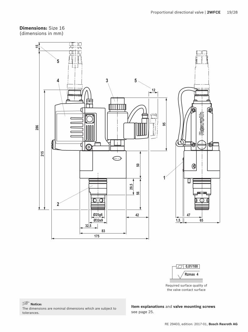
Rzmax 4
001100
4
5
3 5
1
2
231
95
302
15
175
12
5072
39
42Oslash34g6Oslash45e9
425
15
93
8547
2028 2WFCE | Proportional directional valve
Bosch Rexroth AG RE 29403 edition 2017-01
Dimensions Size 25 (dimensions in mm)
NoticeThe dimensions are nominal dimensions which are subject to tolerances
Item explanations and valve mounting screws see page 25
Required surface quality of the valve contact surface
4
5
3 5
1
2
244
50
95
85
35
315
15
42Oslash45g6Oslash60e9
50
15
100175
12
100
Rzmax 4
001100
Proportional directional valve | 2WFCE 2128
RE 29403 edition 2017-01 Bosch Rexroth AG
Dimensions Size 32 (dimensions in mm)
NoticeThe dimensions are nominal dimensions which are subject to tolerances
Item explanations and valve mounting screws see page 25
Required surface quality of the valve contact surface
Rzmax 4
001100
4
5
3 5
264
95
335
15
12
1
2
5010
5
40
22
Oslash55g6Oslash75e9
625
15
125 45190
125
2228 2WFCE | Proportional directional valve
Bosch Rexroth AG RE 29403 edition 2017-01
Dimensions Size 40 (dimensions in mm)
NoticeThe dimensions are nominal dimensions which are subject to tolerances
Item explanations and valve mounting screws see page 25
Required surface quality of the valve contact surface
Rzmax 4
001100
4
5
3 5
281
95
352
15
12
1
Oslash68g6Oslash90e9
70140 38190
140
5012
2
32
47
2
Proportional directional valve | 2WFCE 2328
RE 29403 edition 2017-01 Bosch Rexroth AG
Dimensions Size 50 (dimensions in mm)
NoticeThe dimensions are nominal dimensions which are subject to tolerances
Item explanations and valve mounting screws see page 25
Required surface quality of the valve contact surface
Rzmax 4x =
Rzmax 8y =
Rz 10z =
OslashD3
H9
H2+0
1
H8H7H3
+01
H6H5
15deg
OslashD2OslashD4
H1
15deg
OslashD1
A
B
9
9 11 10 12
L1
L4plusmn0
2
L6plusmn02
X YL7plusmn0
2
bdquoAldquo
L2L3
L4plusmn02
L5plusmn02 L5plusmn02
bdquoAldquo
8 7
6
H4
D5
H10
D7H13
OslashD6
OslashD6
y
y
z
01 A y 001 100A
Oslash003 A
2428 2WFCE | Proportional directional valve
Bosch Rexroth AG RE 29403 edition 2017-01
Installation bore (dimensions in mm)
Installation dimensions according to DIN ISO 7368 NG 16 25 32 40 50OslashD1H7 32 45 60 75 90OslashD2 16 25 32 40 50OslashD3 16 25 32 40 50max OslashD3 25 32 40 50 63OslashD4H7 25 34 45 55 68D5 M8 M12 M16 M20 M20max OslashD6 4 6 8 8 10OslashD7H13 4 6 6 6 8H1 34 44 52 64 72H1 1) 295 405 48 59 655H2 56 72 85 105 122H3 43 58 70 87 100H4 20 25 35 45 45H5 11 12 13 15 17H6 2 25 25 3 3H7 20 30 30 30 35H8 2 25 25 3 4min H9 2) 05 1 15 25 25min H10 8 8 8 8 8L1 65 85 100 125 140L2 83 93 100 125 140L3 325 425 50 625 70L4 46 58 70 85 100L5 25 33 41 50 58L6 105 16 17 23 30L7 23 29 35 425 50
NG Installation dimensions according to DIN ISO 736816 ISO 7368-BA-06-2-A25 ISO 7368-BB-08-2-A32 ISO 7368-BC-09-2-A40 ISO 7368-BD-10-2-A50 ISO 7368-BE-11-2-A
1) Bore center at OslashD3 max2) Control dimension
Tolerances according to General tolerances ISO 2768-mK
Item explanations and valve mounting screws see page 25
Section A ndash A
Proportional directional valve | 2WFCE 2528
RE 29403 edition 2017-01 Bosch Rexroth AG
Dimensions
1 Cover2 Main stage3 Pilot control valve with proportional solenoid4 Integrated electronics with position transducer and analog
interface5 Space required to remove the mating connectors6 Port X7 Port Y8 Locating hole for locking pin9 Depth of fit
10 Control dimension11 Port B may be at any position around the central axis of port
A However it must be observed that the mounting bores and the control bores are not damaged
12 If a different diameter is used for port B than indicated in the dimensional table the distance from the cover support surface to the bore center must be calculated
Valve mounting screws (separate order)Size Hexagon socket head cap screws Material number16 4 hexagon socket head cap screws ISO 4762 - M8 x 30 - 109 - N67F 821 70
(galvanized according to Bosch standard N67F821 70) Tightening torque MA = 35 plusmn5 Nm
2910151246
25 4 hexagon socket head cap screws ISO 4762 - M12 x 40 - 109 - N67F 821 70 (galvanized according to Bosch standard N67F821 70) Tightening torque MA = 105 plusmn15 Nm
2910151346
32 4 hexagon socket head cap screws ISO 4762 - M16 x 50 - 109 - N67F 821 70 (galvanized according to Bosch standard N67F821 70) Tightening torque MA = 265 plusmn25 Nm
2910151442
40 4 hexagon socket head cap screws ISO 4762 - M20 x 60 - 109 - N67F 821 70 (galvanized according to Bosch standard N67F821 70) Tightening torque MA = 500 plusmn50 Nm
2910151526
50
2628 2WFCE | Proportional directional valve
Bosch Rexroth AG RE 29403 edition 2017-01
Connector connection version 6 + PE Mating connector Version Material numberRound connector according to EN 175201-804 (7-pole plastic variant)
Mating connector (assembly kit) for a cable diameter of 65 11 mm
R900021267
Mating connector with 3 m cable 7 x 075 mm2 assembled R901420483Mating connector with 5 m cable 7 x 075 mm2 assembled R901420491Mating connector with 10 m cable 7 x 075 mm2 assembled R901420496
91 Oslash27
AB
CD
E
F
Round connector according to EN 175201-804 (7-pole metal design)
Mating connector (assembly kit) for a cable diameter of 80 135 mm
R900223890
AB
C DE
F
85 Oslash284
Accessories (separate order)
Proportional directional valve | 2WFCE 2728
RE 29403 edition 2017-01 Bosch Rexroth AG
Connector connection version 11 + PE Mating connector Version Material numberMating connector according to DIN EN 175201-804 (12-pole metal design)
Mating connector (assembly kit) for a cable diameter of 12 15 mm
R901268000
Mating connector with 5 m cable 12 x 075 mm2 with cable shield assembled
R901272854
Mating connector with 20 m cable 12 x 075 mm2 with cable shield assembled
R901272852
41~91 Oslash28
SW22
M26 x 15SW
24
1
2
456
7
8911
10 3
Mating connector according to DIN EN 175201-804 (12 pole plastic variant)
Mating connector (assembly kit) R900884671Mating connector with 2 x 5 m cable supply line (3 x 10 mm2) and signal line (10 x 014 mm2) separated with cable shield assembled
R900032356
Mating connector with 2 x 20 m cable supply line (3 x 10 mm2) and signal line (10 x 014 mm2) separated with cable shield assembled
R900860399
1
2
456
7
8911
10 3
33
90
Accessories (separate order)
Bosch Rexroth AG RE 29403 edition 2017-01
2828 2WFCE | Proportional directional valve
Bosch Rexroth AG HydraulicsZum Eisengieszliger 197816 Lohr am Main Germany Phone +49 (0) 93 52thinspthinsp18-0 documentationboschrexrothde wwwboschrexrothde
copy This document as well as the data specifications and other information set forth in it are the exclusive property of Bosch Rexroth AG It may not be reproduced or given to third parties without its consentThe data specified above only serve to describe the product No statements concerning a certain condition or suitability for a certain application can be derived from our information The information given does not release the user from the obligation of own judgment and verification It must be remembered that our products are subject to a natural process of wear and aging
Further information
Hydraulic fluids on mineral oil basis Data sheet 90220 Environmentally compatible hydraulic fluids Data sheet 90221 Flame-resistant water-free hydraulic fluids Data sheet 90222 Flame-resistant hydraulic fluids - containing water (HFAE HFAS HFB HFC) Data sheet 90223 Reliability characteristics according to EN ISO 13849 Data sheet 08012 Hydraulic valves for industrial applications Operating instructions 07600-B Selection of filters wwwboschrexrothcomfilter Information on available spare parts wwwboschrexrothcomspc
- Features
- Contents
- Ordering code
- Function section symbol
- Technical data
- Integrated electronics (OBE)
- Block diagramcontroller function block
- Electrical connections and assignment
- Characteristic curves
- Dimensions
- Installation bore
- Accessories
- Further information
-

4
5
3 5
1
2
244
50
95
85
35
315
15
42Oslash45g6Oslash60e9
50
15
100175
12
100
Rzmax 4
001100
Proportional directional valve | 2WFCE 2128
RE 29403 edition 2017-01 Bosch Rexroth AG
Dimensions Size 32 (dimensions in mm)
NoticeThe dimensions are nominal dimensions which are subject to tolerances
Item explanations and valve mounting screws see page 25
Required surface quality of the valve contact surface
Rzmax 4
001100
4
5
3 5
264
95
335
15
12
1
2
5010
5
40
22
Oslash55g6Oslash75e9
625
15
125 45190
125
2228 2WFCE | Proportional directional valve
Bosch Rexroth AG RE 29403 edition 2017-01
Dimensions Size 40 (dimensions in mm)
NoticeThe dimensions are nominal dimensions which are subject to tolerances
Item explanations and valve mounting screws see page 25
Required surface quality of the valve contact surface
Rzmax 4
001100
4
5
3 5
281
95
352
15
12
1
Oslash68g6Oslash90e9
70140 38190
140
5012
2
32
47
2
Proportional directional valve | 2WFCE 2328
RE 29403 edition 2017-01 Bosch Rexroth AG
Dimensions Size 50 (dimensions in mm)
NoticeThe dimensions are nominal dimensions which are subject to tolerances
Item explanations and valve mounting screws see page 25
Required surface quality of the valve contact surface
Rzmax 4x =
Rzmax 8y =
Rz 10z =
OslashD3
H9
H2+0
1
H8H7H3
+01
H6H5
15deg
OslashD2OslashD4
H1
15deg
OslashD1
A
B
9
9 11 10 12
L1
L4plusmn0
2
L6plusmn02
X YL7plusmn0
2
bdquoAldquo
L2L3
L4plusmn02
L5plusmn02 L5plusmn02
bdquoAldquo
8 7
6
H4
D5
H10
D7H13
OslashD6
OslashD6
y
y
z
01 A y 001 100A
Oslash003 A
2428 2WFCE | Proportional directional valve
Bosch Rexroth AG RE 29403 edition 2017-01
Installation bore (dimensions in mm)
Installation dimensions according to DIN ISO 7368 NG 16 25 32 40 50OslashD1H7 32 45 60 75 90OslashD2 16 25 32 40 50OslashD3 16 25 32 40 50max OslashD3 25 32 40 50 63OslashD4H7 25 34 45 55 68D5 M8 M12 M16 M20 M20max OslashD6 4 6 8 8 10OslashD7H13 4 6 6 6 8H1 34 44 52 64 72H1 1) 295 405 48 59 655H2 56 72 85 105 122H3 43 58 70 87 100H4 20 25 35 45 45H5 11 12 13 15 17H6 2 25 25 3 3H7 20 30 30 30 35H8 2 25 25 3 4min H9 2) 05 1 15 25 25min H10 8 8 8 8 8L1 65 85 100 125 140L2 83 93 100 125 140L3 325 425 50 625 70L4 46 58 70 85 100L5 25 33 41 50 58L6 105 16 17 23 30L7 23 29 35 425 50
NG Installation dimensions according to DIN ISO 736816 ISO 7368-BA-06-2-A25 ISO 7368-BB-08-2-A32 ISO 7368-BC-09-2-A40 ISO 7368-BD-10-2-A50 ISO 7368-BE-11-2-A
1) Bore center at OslashD3 max2) Control dimension
Tolerances according to General tolerances ISO 2768-mK
Item explanations and valve mounting screws see page 25
Section A ndash A
Proportional directional valve | 2WFCE 2528
RE 29403 edition 2017-01 Bosch Rexroth AG
Dimensions
1 Cover2 Main stage3 Pilot control valve with proportional solenoid4 Integrated electronics with position transducer and analog
interface5 Space required to remove the mating connectors6 Port X7 Port Y8 Locating hole for locking pin9 Depth of fit
10 Control dimension11 Port B may be at any position around the central axis of port
A However it must be observed that the mounting bores and the control bores are not damaged
12 If a different diameter is used for port B than indicated in the dimensional table the distance from the cover support surface to the bore center must be calculated
Valve mounting screws (separate order)Size Hexagon socket head cap screws Material number16 4 hexagon socket head cap screws ISO 4762 - M8 x 30 - 109 - N67F 821 70
(galvanized according to Bosch standard N67F821 70) Tightening torque MA = 35 plusmn5 Nm
2910151246
25 4 hexagon socket head cap screws ISO 4762 - M12 x 40 - 109 - N67F 821 70 (galvanized according to Bosch standard N67F821 70) Tightening torque MA = 105 plusmn15 Nm
2910151346
32 4 hexagon socket head cap screws ISO 4762 - M16 x 50 - 109 - N67F 821 70 (galvanized according to Bosch standard N67F821 70) Tightening torque MA = 265 plusmn25 Nm
2910151442
40 4 hexagon socket head cap screws ISO 4762 - M20 x 60 - 109 - N67F 821 70 (galvanized according to Bosch standard N67F821 70) Tightening torque MA = 500 plusmn50 Nm
2910151526
50
2628 2WFCE | Proportional directional valve
Bosch Rexroth AG RE 29403 edition 2017-01
Connector connection version 6 + PE Mating connector Version Material numberRound connector according to EN 175201-804 (7-pole plastic variant)
Mating connector (assembly kit) for a cable diameter of 65 11 mm
R900021267
Mating connector with 3 m cable 7 x 075 mm2 assembled R901420483Mating connector with 5 m cable 7 x 075 mm2 assembled R901420491Mating connector with 10 m cable 7 x 075 mm2 assembled R901420496
91 Oslash27
AB
CD
E
F
Round connector according to EN 175201-804 (7-pole metal design)
Mating connector (assembly kit) for a cable diameter of 80 135 mm
R900223890
AB
C DE
F
85 Oslash284
Accessories (separate order)
Proportional directional valve | 2WFCE 2728
RE 29403 edition 2017-01 Bosch Rexroth AG
Connector connection version 11 + PE Mating connector Version Material numberMating connector according to DIN EN 175201-804 (12-pole metal design)
Mating connector (assembly kit) for a cable diameter of 12 15 mm
R901268000
Mating connector with 5 m cable 12 x 075 mm2 with cable shield assembled
R901272854
Mating connector with 20 m cable 12 x 075 mm2 with cable shield assembled
R901272852
41~91 Oslash28
SW22
M26 x 15SW
24
1
2
456
7
8911
10 3
Mating connector according to DIN EN 175201-804 (12 pole plastic variant)
Mating connector (assembly kit) R900884671Mating connector with 2 x 5 m cable supply line (3 x 10 mm2) and signal line (10 x 014 mm2) separated with cable shield assembled
R900032356
Mating connector with 2 x 20 m cable supply line (3 x 10 mm2) and signal line (10 x 014 mm2) separated with cable shield assembled
R900860399
1
2
456
7
8911
10 3
33
90
Accessories (separate order)
Bosch Rexroth AG RE 29403 edition 2017-01
2828 2WFCE | Proportional directional valve
Bosch Rexroth AG HydraulicsZum Eisengieszliger 197816 Lohr am Main Germany Phone +49 (0) 93 52thinspthinsp18-0 documentationboschrexrothde wwwboschrexrothde
copy This document as well as the data specifications and other information set forth in it are the exclusive property of Bosch Rexroth AG It may not be reproduced or given to third parties without its consentThe data specified above only serve to describe the product No statements concerning a certain condition or suitability for a certain application can be derived from our information The information given does not release the user from the obligation of own judgment and verification It must be remembered that our products are subject to a natural process of wear and aging
Further information
Hydraulic fluids on mineral oil basis Data sheet 90220 Environmentally compatible hydraulic fluids Data sheet 90221 Flame-resistant water-free hydraulic fluids Data sheet 90222 Flame-resistant hydraulic fluids - containing water (HFAE HFAS HFB HFC) Data sheet 90223 Reliability characteristics according to EN ISO 13849 Data sheet 08012 Hydraulic valves for industrial applications Operating instructions 07600-B Selection of filters wwwboschrexrothcomfilter Information on available spare parts wwwboschrexrothcomspc
- Features
- Contents
- Ordering code
- Function section symbol
- Technical data
- Integrated electronics (OBE)
- Block diagramcontroller function block
- Electrical connections and assignment
- Characteristic curves
- Dimensions
- Installation bore
- Accessories
- Further information
-
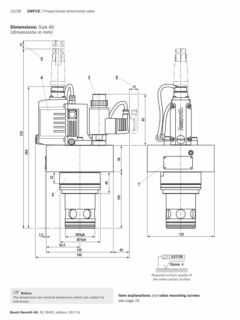
Rzmax 4
001100
4
5
3 5
281
95
352
15
12
1
Oslash68g6Oslash90e9
70140 38190
140
5012
2
32
47
2
Proportional directional valve | 2WFCE 2328
RE 29403 edition 2017-01 Bosch Rexroth AG
Dimensions Size 50 (dimensions in mm)
NoticeThe dimensions are nominal dimensions which are subject to tolerances
Item explanations and valve mounting screws see page 25
Required surface quality of the valve contact surface
Rzmax 4x =
Rzmax 8y =
Rz 10z =
OslashD3
H9
H2+0
1
H8H7H3
+01
H6H5
15deg
OslashD2OslashD4
H1
15deg
OslashD1
A
B
9
9 11 10 12
L1
L4plusmn0
2
L6plusmn02
X YL7plusmn0
2
bdquoAldquo
L2L3
L4plusmn02
L5plusmn02 L5plusmn02
bdquoAldquo
8 7
6
H4
D5
H10
D7H13
OslashD6
OslashD6
y
y
z
01 A y 001 100A
Oslash003 A
2428 2WFCE | Proportional directional valve
Bosch Rexroth AG RE 29403 edition 2017-01
Installation bore (dimensions in mm)
Installation dimensions according to DIN ISO 7368 NG 16 25 32 40 50OslashD1H7 32 45 60 75 90OslashD2 16 25 32 40 50OslashD3 16 25 32 40 50max OslashD3 25 32 40 50 63OslashD4H7 25 34 45 55 68D5 M8 M12 M16 M20 M20max OslashD6 4 6 8 8 10OslashD7H13 4 6 6 6 8H1 34 44 52 64 72H1 1) 295 405 48 59 655H2 56 72 85 105 122H3 43 58 70 87 100H4 20 25 35 45 45H5 11 12 13 15 17H6 2 25 25 3 3H7 20 30 30 30 35H8 2 25 25 3 4min H9 2) 05 1 15 25 25min H10 8 8 8 8 8L1 65 85 100 125 140L2 83 93 100 125 140L3 325 425 50 625 70L4 46 58 70 85 100L5 25 33 41 50 58L6 105 16 17 23 30L7 23 29 35 425 50
NG Installation dimensions according to DIN ISO 736816 ISO 7368-BA-06-2-A25 ISO 7368-BB-08-2-A32 ISO 7368-BC-09-2-A40 ISO 7368-BD-10-2-A50 ISO 7368-BE-11-2-A
1) Bore center at OslashD3 max2) Control dimension
Tolerances according to General tolerances ISO 2768-mK
Item explanations and valve mounting screws see page 25
Section A ndash A
Proportional directional valve | 2WFCE 2528
RE 29403 edition 2017-01 Bosch Rexroth AG
Dimensions
1 Cover2 Main stage3 Pilot control valve with proportional solenoid4 Integrated electronics with position transducer and analog
interface5 Space required to remove the mating connectors6 Port X7 Port Y8 Locating hole for locking pin9 Depth of fit
10 Control dimension11 Port B may be at any position around the central axis of port
A However it must be observed that the mounting bores and the control bores are not damaged
12 If a different diameter is used for port B than indicated in the dimensional table the distance from the cover support surface to the bore center must be calculated
Valve mounting screws (separate order)Size Hexagon socket head cap screws Material number16 4 hexagon socket head cap screws ISO 4762 - M8 x 30 - 109 - N67F 821 70
(galvanized according to Bosch standard N67F821 70) Tightening torque MA = 35 plusmn5 Nm
2910151246
25 4 hexagon socket head cap screws ISO 4762 - M12 x 40 - 109 - N67F 821 70 (galvanized according to Bosch standard N67F821 70) Tightening torque MA = 105 plusmn15 Nm
2910151346
32 4 hexagon socket head cap screws ISO 4762 - M16 x 50 - 109 - N67F 821 70 (galvanized according to Bosch standard N67F821 70) Tightening torque MA = 265 plusmn25 Nm
2910151442
40 4 hexagon socket head cap screws ISO 4762 - M20 x 60 - 109 - N67F 821 70 (galvanized according to Bosch standard N67F821 70) Tightening torque MA = 500 plusmn50 Nm
2910151526
50
2628 2WFCE | Proportional directional valve
Bosch Rexroth AG RE 29403 edition 2017-01
Connector connection version 6 + PE Mating connector Version Material numberRound connector according to EN 175201-804 (7-pole plastic variant)
Mating connector (assembly kit) for a cable diameter of 65 11 mm
R900021267
Mating connector with 3 m cable 7 x 075 mm2 assembled R901420483Mating connector with 5 m cable 7 x 075 mm2 assembled R901420491Mating connector with 10 m cable 7 x 075 mm2 assembled R901420496
91 Oslash27
AB
CD
E
F
Round connector according to EN 175201-804 (7-pole metal design)
Mating connector (assembly kit) for a cable diameter of 80 135 mm
R900223890
AB
C DE
F
85 Oslash284
Accessories (separate order)
Proportional directional valve | 2WFCE 2728
RE 29403 edition 2017-01 Bosch Rexroth AG
Connector connection version 11 + PE Mating connector Version Material numberMating connector according to DIN EN 175201-804 (12-pole metal design)
Mating connector (assembly kit) for a cable diameter of 12 15 mm
R901268000
Mating connector with 5 m cable 12 x 075 mm2 with cable shield assembled
R901272854
Mating connector with 20 m cable 12 x 075 mm2 with cable shield assembled
R901272852
41~91 Oslash28
SW22
M26 x 15SW
24
1
2
456
7
8911
10 3
Mating connector according to DIN EN 175201-804 (12 pole plastic variant)
Mating connector (assembly kit) R900884671Mating connector with 2 x 5 m cable supply line (3 x 10 mm2) and signal line (10 x 014 mm2) separated with cable shield assembled
R900032356
Mating connector with 2 x 20 m cable supply line (3 x 10 mm2) and signal line (10 x 014 mm2) separated with cable shield assembled
R900860399
1
2
456
7
8911
10 3
33
90
Accessories (separate order)
Bosch Rexroth AG RE 29403 edition 2017-01
2828 2WFCE | Proportional directional valve
Bosch Rexroth AG HydraulicsZum Eisengieszliger 197816 Lohr am Main Germany Phone +49 (0) 93 52thinspthinsp18-0 documentationboschrexrothde wwwboschrexrothde
copy This document as well as the data specifications and other information set forth in it are the exclusive property of Bosch Rexroth AG It may not be reproduced or given to third parties without its consentThe data specified above only serve to describe the product No statements concerning a certain condition or suitability for a certain application can be derived from our information The information given does not release the user from the obligation of own judgment and verification It must be remembered that our products are subject to a natural process of wear and aging
Further information
Hydraulic fluids on mineral oil basis Data sheet 90220 Environmentally compatible hydraulic fluids Data sheet 90221 Flame-resistant water-free hydraulic fluids Data sheet 90222 Flame-resistant hydraulic fluids - containing water (HFAE HFAS HFB HFC) Data sheet 90223 Reliability characteristics according to EN ISO 13849 Data sheet 08012 Hydraulic valves for industrial applications Operating instructions 07600-B Selection of filters wwwboschrexrothcomfilter Information on available spare parts wwwboschrexrothcomspc
- Features
- Contents
- Ordering code
- Function section symbol
- Technical data
- Integrated electronics (OBE)
- Block diagramcontroller function block
- Electrical connections and assignment
- Characteristic curves
- Dimensions
- Installation bore
- Accessories
- Further information
-