RD400 User Manual
46
RD400 Digital Series User Guide Revision 2 8/2000
Transcript of RD400 User Manual

RD400 Digital SeriesUser Guide
Revision 2 8/2000
RD400 Digital Series User Guide
Trouble Shooting
When reporting any problem to your Radiodetection Dealer/Supplier it is important to quote the following:
Receiver Serial Number.Software Revision Number.Software Revision Number is displayed on the LCD during switch on.
WarningRadiodetection Receivers detect almost all buried cables and most conductors, but there aresome which do not radiate signals and which Radiodetection Receivers cannot detect.Radiodetection Receivers do not indicate whether a signal is from a single cable, several buriedside by side or one above another.
This equipment is NOT approved for use in areas where hazardous gases may be present.
Reduce audio level before using headphones.
Ni-Cad batteries should be disposed of in accordance with your Company's work practice, and/orthe relevant law or guidelines in your country.
WarningThe operation of any cable and pipe locator may be affected when used in close proximity toferrous materials such as manhole covers and parked cars. Keep a one or two meter distancefrom these objects when taking critical measurements such as depth and current readings.Standing too close to the locator when wearing steel toe capped boots may also affect thereadings.
This instrument, or family of instruments, will not be permanently damaged by reasonable electrostaticdischarge and has been tested in accordance with IEC 801-2. However, in extreme cases temporarymalfunction may occur. If this happens, switch off, wait and switch on again. If the instrument stillmalfunctions, disconnect the batteries for a few seconds.

RD400 Digital Series User Guide
CONTENTS
Title Page
RD400PXL-2 Precision Locator ..................................................................................................................1Error Codes........................................................................................................................................4
RD432PDL Precision Locator .....................................................................................................................5Error Codes........................................................................................................................................8
RD400PXL Precision Locator .....................................................................................................................9Error Codes......................................................................................................................................11
RD400SL2 Locator....................................................................................................................................12Error Codes......................................................................................................................................13
Receiver Use.............................................................................................................................................15Locate...............................................................................................................................................15Radio Mode......................................................................................................................................15Active Mode......................................................................................................................................15Pinpoint ............................................................................................................................................16Null .................................................................................................................................................17Depth Reading to a Line ..................................................................................................................17Depth in Power Mode.......................................................................................................................18Current .............................................................................................................................................18
CD (RD400PXL-2 and RD432PDL) ........................................................................................18CD Reset .................................................................................................................................18CD Read..................................................................................................................................19
Pinpointing a Sonde .........................................................................................................................19Depth Reading to a Sonde...............................................................................................................19
RD Accessory A-Frame ............................................................................................................................20Transmitter Setup.............................................................................................................................20Cable Fault Finding with the A-Frame .............................................................................................21
CD Signal Method ...................................................................................................................21FF Signal Method ....................................................................................................................22
Difficult Ground Conditions ..............................................................................................................24
RD433HCTx-2 Multi-Frequency Transmitter ............................................................................................25
RD400LCTx Lightweight Compact Transmitter ........................................................................................29
RD400STx Standard Power Transmitter ..................................................................................................30
RD400SDTx Standard Power Transmitter................................................................................................31
RD400HPTx High Power Transmitter .......................................................................................................33
RD433HCTx High Power Transmitter.......................................................................................................35
Transmitter Use.........................................................................................................................................37Induction...........................................................................................................................................37Direct Connection.............................................................................................................................37Signal Clamp....................................................................................................................................38Liver Plug Connector........................................................................................................................38

RD400 Digital Series User Guide
RD400 Digital Series User Guide
About this User GuideThis User Guide is divided into sections as follows:
RD400 Digital Receivers
These sections detail where to find and how to use the various operating controls and features, etc.,relevant to each Receiver in the RD400 Digital Series range.
As there are several RD400PXL-2 variants, some of the features described in the PXL-2 Receiver Sectionmay not be available. Refer to the product label for features available.
Receiver Use
This section describes how to locate, trace, pinpoint, measure depth/current and find current directionusing the RD400 Digital Series Receivers.
RD400 Transmitters
These sections detail where to find and how to use the various operating controls and features, etc.,relevant to each Transmitter in the RD400 Series range.
Transmitter Use
This section describes how to apply a signal to a target line using the RD400 Series Transmitters.

RD400 Digital Series User Guide
RD400 Digital Series User Guide
Page 1
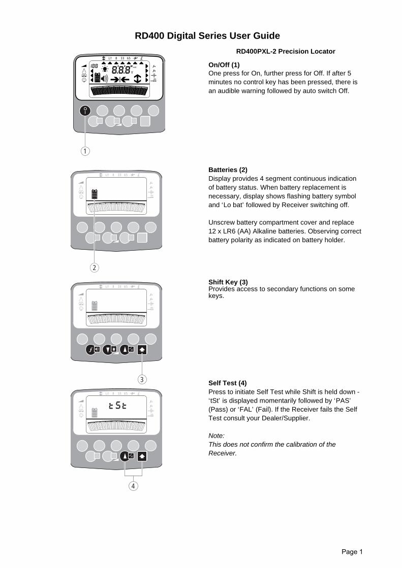
RD400PXL-2 Precision Locator
On/Off (1)One press for On, further press for Off. If after 5minutes no control key has been pressed, there isan audible warning followed by auto switch Off.
Batteries (2)Display provides 4 segment continuous indicationof battery status. When battery replacement isnecessary, display shows flashing battery symboland ‘Lo bat’ followed by Receiver switching off.
Unscrew battery compartment cover and replace12 x LR6 (AA) Alkaline batteries. Observing correctbattery polarity as indicated on battery holder.
Shift Key (3)Provides access to secondary functions on somekeys.
Self Test (4)Press to initiate Self Test while Shift is held down -‘tSt’ is displayed momentarily followed by ‘PAS’(Pass) or ‘FAL’ (Fail). If the Receiver fails the SelfTest consult your Dealer/Supplier.
Note:This does not confirm the calibration of theReceiver.
1
mA
8 33 65Lf
a
b
2
8 33 65Lf
a
b
3
8 33 65Lf
a
b
4
8 33 65Lf
a
b
RD400 Digital Series User Guide
Page 2
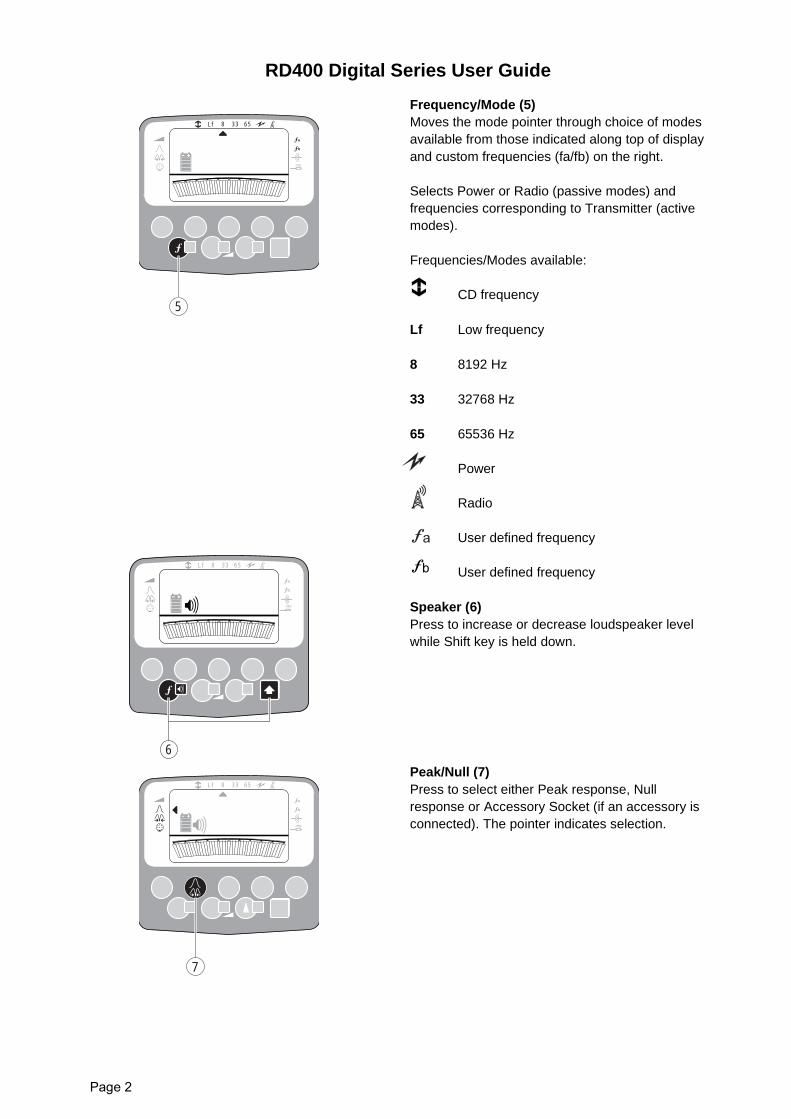
Frequency/Mode (5)Moves the mode pointer through choice of modesavailable from those indicated along top of displayand custom frequencies (fa/fb) on the right.
Selects Power or Radio (passive modes) andfrequencies corresponding to Transmitter (activemodes).
Frequencies/Modes available:
CD frequency
Lf Low frequency
8 8192 Hz
33 32768 Hz
65 65536 Hz
Power
Radio
User defined frequency
User defined frequency
Speaker (6)Press to increase or decrease loudspeaker levelwhile Shift key is held down.
Peak/Null (7)Press to select either Peak response, Nullresponse or Accessory Socket (if an accessory isconnected). The pointer indicates selection.
5
8 33 65Lf
a
b
6
8 33 65Lf
a
b
7
8 33 65Lf
a
b
RD400 Digital Series User Guide
Page 3
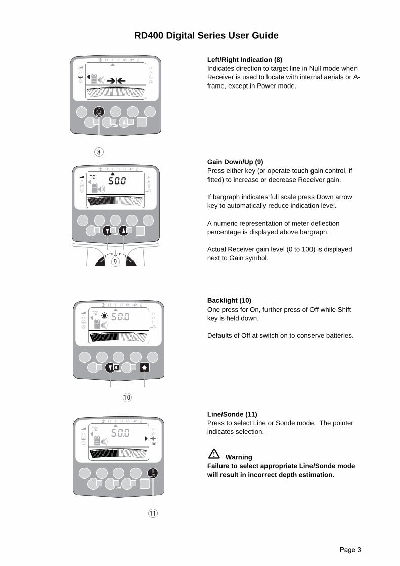
Left/Right Indication (8)Indicates direction to target line in Null mode whenReceiver is used to locate with internal aerials or A-frame, except in Power mode.
Gain Down/Up (9)Press either key (or operate touch gain control, iffitted) to increase or decrease Receiver gain.
If bargraph indicates full scale press Down arrowkey to automatically reduce indication level.
A numeric representation of meter deflectionpercentage is displayed above bargraph.
Actual Receiver gain level (0 to 100) is displayednext to Gain symbol.
Backlight (10)One press for On, further press of Off while Shiftkey is held down.
Defaults of Off at switch on to conserve batteries.
Line/Sonde (11)Press to select Line or Sonde mode. The pointerindicates selection.
WarningFailure to select appropriate Line/Sonde modewill result in incorrect depth estimation.
8
8 33 65Lf
a
b
9
8 33 65Lf
a
b
10
8 33 65Lf
a
b
11
8 33 65Lf
a
b
RD400 Digital Series User Guide
Page 4
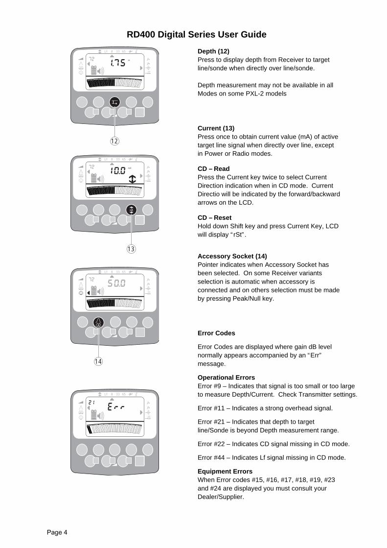
Depth (12)Press to display depth from Receiver to targetline/sonde when directly over line/sonde.
Depth measurement may not be available in allModes on some PXL-2 models
Current (13)Press once to obtain current value (mA) of activetarget line signal when directly over line, exceptin Power or Radio modes.
CD – ReadPress the Current key twice to select CurrentDirection indication when in CD mode. CurrentDirectio will be indicated by the forward/backwardarrows on the LCD.
CD – ResetHold down Shift key and press Current Key, LCDwill display “rSt”.
Accessory Socket (14)Pointer indicates when Accessory Socket hasbeen selected. On some Receiver variantsselection is automatic when accessory isconnected and on others selection must be madeby pressing Peak/Null key.
Error Codes
Error Codes are displayed where gain dB levelnormally appears accompanied by an “Err”message.
Operational ErrorsError #9 – Indicates that signal is too small or too largeto measure Depth/Current. Check Transmitter settings.
Error #11 – Indicates a strong overhead signal.
Error #21 – Indicates that depth to targetline/Sonde is beyond Depth measurement range.
Error #22 – Indicates CD signal missing in CD mode.
Error #44 – Indicates Lf signal missing in CD mode.
Equipment ErrorsWhen Error codes #15, #16, #17, #18, #19, #23and #24 are displayed you must consult yourDealer/Supplier.
12
m
8 33 65Lf
a
b
13
8 33 65Lf
a
b
mA
14
8 33 65Lf
a
b
8 33 65Lf
a
b
RD400 Digital Series User Guide
Page 5
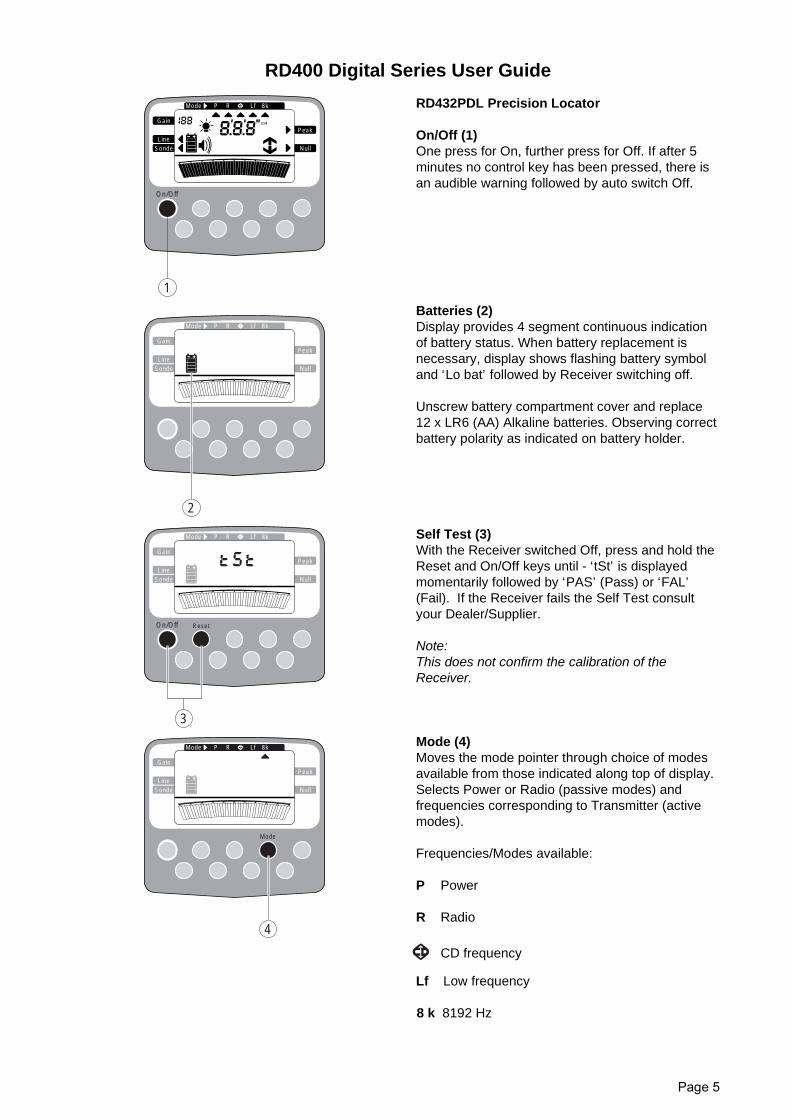
RD432PDL Precision Locator
On/Off (1)One press for On, further press for Off. If after 5minutes no control key has been pressed, there isan audible warning followed by auto switch Off.
Batteries (2)Display provides 4 segment continuous indicationof battery status. When battery replacement isnecessary, display shows flashing battery symboland ‘Lo bat’ followed by Receiver switching off.
Unscrew battery compartment cover and replace12 x LR6 (AA) Alkaline batteries. Observing correctbattery polarity as indicated on battery holder.
Self Test (3)With the Receiver switched Off, press and hold theReset and On/Off keys until - ‘tSt’ is displayedmomentarily followed by ‘PAS’ (Pass) or ‘FAL’(Fail). If the Receiver fails the Self Test consultyour Dealer/Supplier.
Note:This does not confirm the calibration of theReceiver.
Mode (4)Moves the mode pointer through choice of modesavailable from those indicated along top of display.Selects Power or Radio (passive modes) andfrequencies corresponding to Transmitter (activemodes).
Frequencies/Modes available:
P Power
R Radio
CD frequency
Lf Low frequency
8 k 8192 Hz
1
On/Off
Gain
SondeLine
Peak
Null
P RMode
mA
Lf 8k
Gain
SondeLine
Peak
Null
P RMode
2
Lf 8k
Gain
SondeLine
Peak
Null
P RMode
3
On/Off Reset
Lf 8k
Gain
SondeLine
Peak
Null
P RMode
Mode
4
Lf 8k
RD400 Digital Series User Guide
Page 6
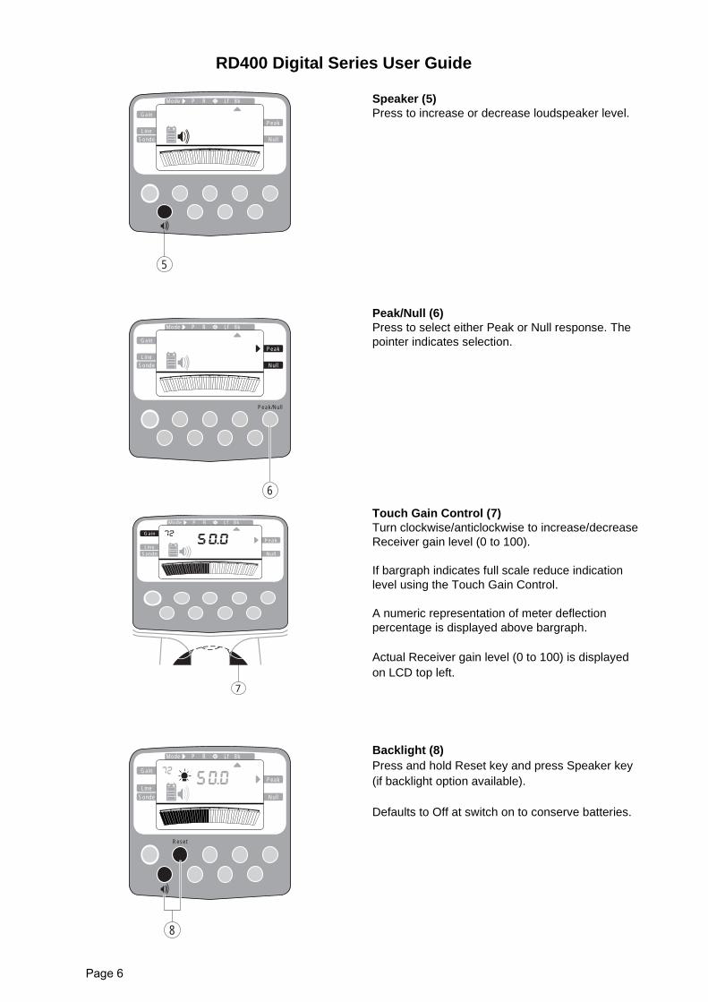
Speaker (5)Press to increase or decrease loudspeaker level.
Peak/Null (6)Press to select either Peak or Null response. Thepointer indicates selection.
Touch Gain Control (7)Turn clockwise/anticlockwise to increase/decreaseReceiver gain level (0 to 100).
If bargraph indicates full scale reduce indicationlevel using the Touch Gain Control.
A numeric representation of meter deflectionpercentage is displayed above bargraph.
Actual Receiver gain level (0 to 100) is displayedon LCD top left.
Backlight (8)Press and hold Reset key and press Speaker key(if backlight option available).
Defaults to Off at switch on to conserve batteries.
Gain
SondeLine
Peak
Null
P RMode
5
Lf 8k
Gain
SondeLine
Peak
Null
P RMode
6
Peak/Null
Lf 8k
Gain
SondeLine
Peak
Null
P RMode
7
Lf 8k
Gain
SondeLine
Peak
Null
P RMode
8
Reset
Lf 8k
RD400 Digital Series User Guide
Page 7
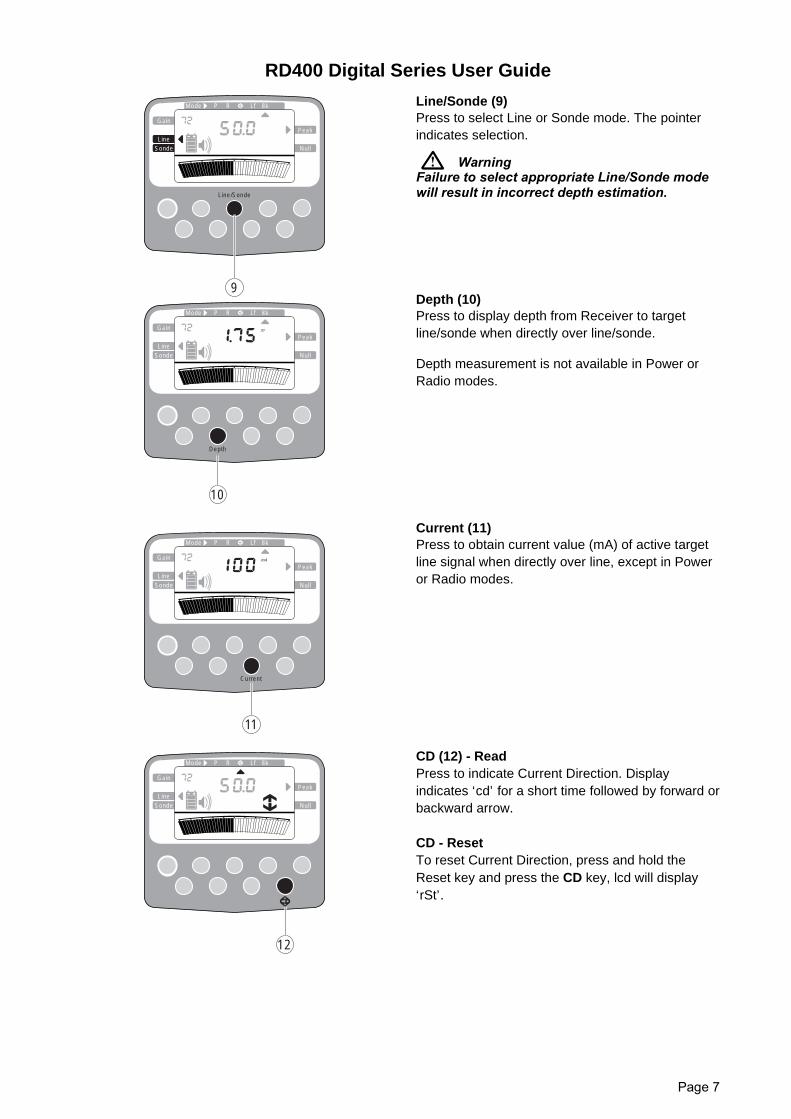
Line/Sonde (9)Press to select Line or Sonde mode. The pointerindicates selection.
WarningFailure to select appropriate Line/Sonde modewill result in incorrect depth estimation.
Depth (10)Press to display depth from Receiver to targetline/sonde when directly over line/sonde.
Depth measurement is not available in Power orRadio modes.
Current (11)Press to obtain current value (mA) of active targetline signal when directly over line, except in Poweror Radio modes.
CD (12) - ReadPress to indicate Current Direction. Displayindicates ‘cd’ for a short time followed by forward orbackward arrow.
CD - ResetTo reset Current Direction, press and hold theReset key and press the CD key, lcd will display‘rSt’.
Gain
SondeLine
Peak
Null
P RMode
10
Depth
m
Lf 8k
Gain
SondeLine
Peak
Null
P RMode
Line/Sonde
9
Lf 8k
Gain
SondeLine
Peak
Null
P RMode
mA
Current
11
Lf 8k
Gain
SondeLine
Peak
Null
P RMode
12
Lf 8k
RD400 Digital Series User Guide
Page 8
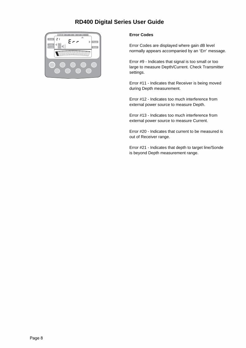
Error Codes
Error Codes are displayed where gain dB levelnormally appears accompanied by an ‘Err’ message.
Error #9 - Indicates that signal is too small or toolarge to measure Depth/Current. Check Transmittersettings.
Error #11 - Indicates that Receiver is being movedduring Depth measurement.
Error #12 - Indicates too much interference fromexternal power source to measure Depth.
Error #13 - Indicates too much interference fromexternal power source to measure Current.
Error #20 - Indicates that current to be measured isout of Receiver range.
Error #21 - Indicates that depth to target line/Sondeis beyond Depth measurement range.
Gain
SondeLine
Peak
Null
P RMode Lf 8k
RD400 Digital Series User Guide
Page 9
RD400PXL Precision Locator
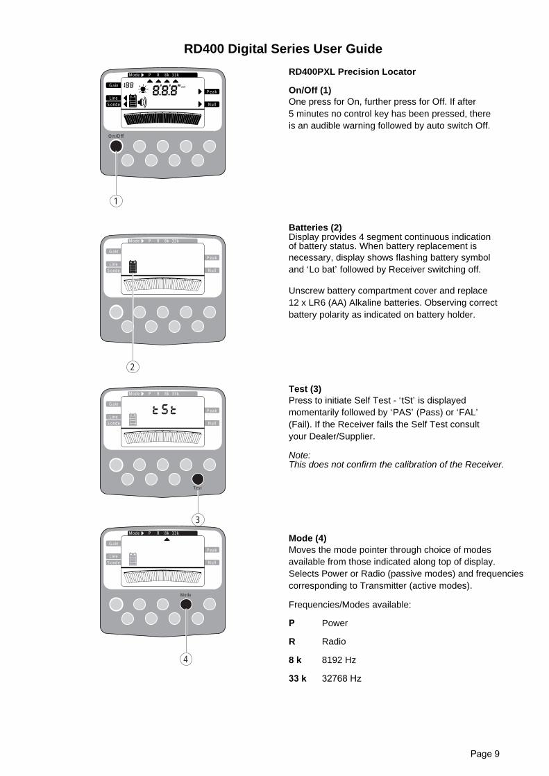
On/Off (1)One press for On, further press for Off. If after5 minutes no control key has been pressed, thereis an audible warning followed by auto switch Off.
Batteries (2)Display provides 4 segment continuous indicationof battery status. When battery replacement isnecessary, display shows flashing battery symboland ‘Lo bat’ followed by Receiver switching off.
Unscrew battery compartment cover and replace12 x LR6 (AA) Alkaline batteries. Observing correctbattery polarity as indicated on battery holder.
Test (3)Press to initiate Self Test - ‘tSt’ is displayedmomentarily followed by ‘PAS’ (Pass) or ‘FAL’(Fail). If the Receiver fails the Self Test consultyour Dealer/Supplier.
Note:This does not confirm the calibration of the Receiver.
Mode (4)Moves the mode pointer through choice of modesavailable from those indicated along top of display.Selects Power or Radio (passive modes) and frequenciescorresponding to Transmitter (active modes).
Frequencies/Modes available:
P Power
R Radio
8 k 8192 Hz
33 k 32768 Hz
1
On/Off
Gain
SondeLine
Peak
Null
P RMode 8k 33k
mA
Gain
SondeLine
Peak
Null
P RMode 8k 33k
2
Gain
SondeLine
Peak
Null
P RMode 8k 33k
3
Test
Gain
SondeLine
Peak
Null
P RMode 8k 33k
Mode
4
RD400 Digital Series User Guide
Page 10
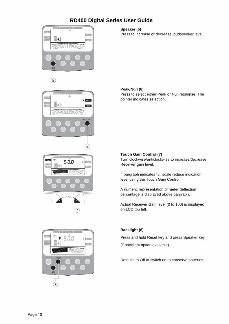
Speaker (5)Press to increase or decrease loudspeaker level.
Peak/Null (6)Press to select either Peak or Null response. Thepointer indicates selection.
Touch Gain Control (7)Turn clockwise/anticlockwise to increase/decreaseReceiver gain level.
If bargraph indicates full scale reduce indicationlevel using the Touch Gain Control.
A numeric representation of meter deflectionpercentage is displayed above bargraph.
Actual Receiver Gain level (0 to 100) is displayedon LCD top left.
Backlight (8)
Press and hold Reset key and press Speaker key
(if backlight option available).
Defaults to Off at switch on to conserve batteries.
Gain
SondeLine
Peak
Null
P RMode 8k 33k
5
Gain
SondeLine
Peak
Null
P RMode 8k 33k
6
Peak/Null
Gain
SondeLine
Peak
Null
P RMode
7
33k8k
Gain
SondeLine
Peak
Null
P RMode 8k 33k
8
Reset
RD400 Digital Series User Guide
Page 11
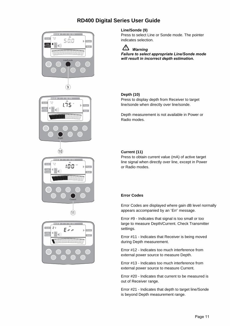
Line/Sonde (9)Press to select Line or Sonde mode. The pointerindicates selection.
WarningFailure to select appropriate Line/Sonde modewill result in incorrect depth estimation.
Depth (10)Press to display depth from Receiver to targetline/sonde when directly over line/sonde.
Depth measurement is not available in Power orRadio modes.
Current (11)Press to obtain current value (mA) of active targetline signal when directly over line, except in Poweror Radio modes.
Error Codes
Error Codes are displayed where gain dB level normallyappears accompanied by an ‘Err’ message.
Error #9 - Indicates that signal is too small or toolarge to measure Depth/Current. Check Transmittersettings.
Error #11 - Indicates that Receiver is being movedduring Depth measurement.
Error #12 - Indicates too much interference fromexternal power source to measure Depth.
Error #13 - Indicates too much interference fromexternal power source to measure Current.
Error #20 - Indicates that current to be measured isout of Receiver range.
Error #21 - Indicates that depth to target line/Sondeis beyond Depth measurement range.
Gain
SondeLine
Peak
Null
P RMode 8k 33k
10
Depth
m
Gain
SondeLine
Peak
Null
P RMode 8k 33k
mA
Current
11
Gain
SondeLine
Peak
Null
P RMode 8k 33k
Gain
SondeLine
Peak
Null
P RMode 8k 33k
Line/Sonde
9
RD400 Digital Series User Guide
Page 12
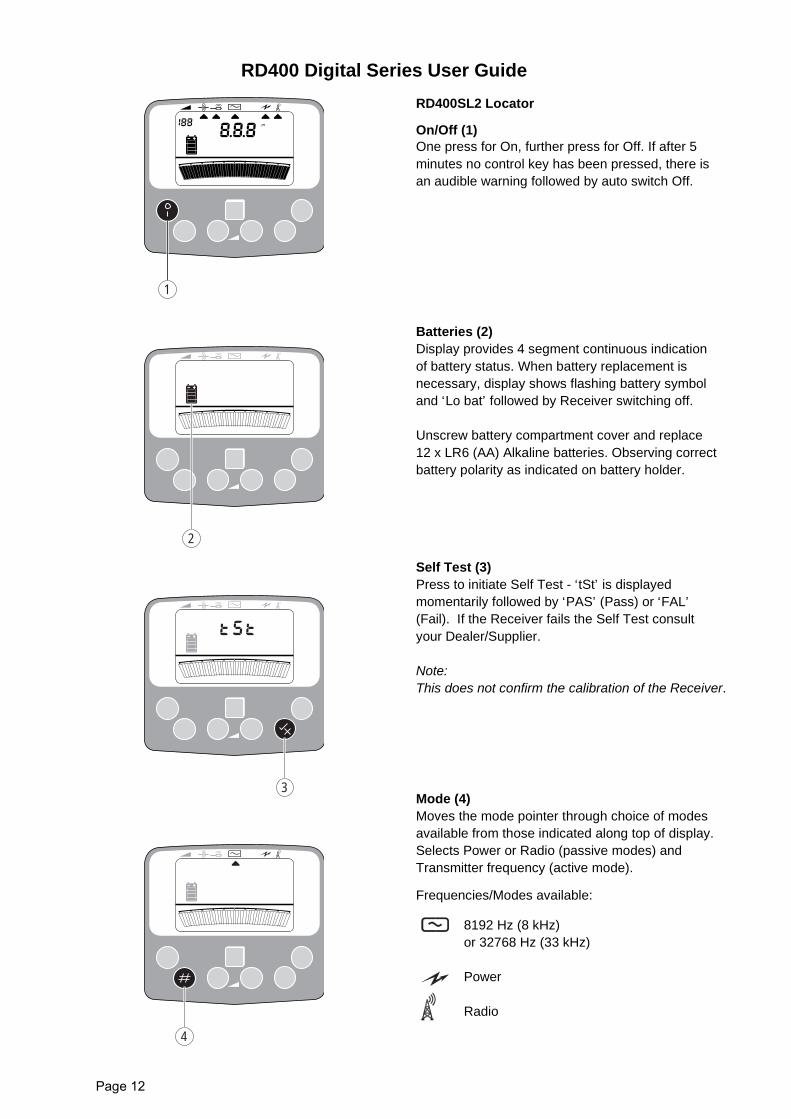
RD400SL2 Locator
On/Off (1)One press for On, further press for Off. If after 5minutes no control key has been pressed, there isan audible warning followed by auto switch Off.
Batteries (2)Display provides 4 segment continuous indicationof battery status. When battery replacement isnecessary, display shows flashing battery symboland ‘Lo bat’ followed by Receiver switching off.
Unscrew battery compartment cover and replace12 x LR6 (AA) Alkaline batteries. Observing correctbattery polarity as indicated on battery holder.
Self Test (3)Press to initiate Self Test - ‘tSt’ is displayedmomentarily followed by ‘PAS’ (Pass) or ‘FAL’(Fail). If the Receiver fails the Self Test consultyour Dealer/Supplier.
Note:This does not confirm the calibration of the Receiver.
Mode (4)Moves the mode pointer through choice of modesavailable from those indicated along top of display.Selects Power or Radio (passive modes) andTransmitter frequency (active mode).
Frequencies/Modes available:
8192 Hz (8 kHz)or 32768 Hz (33 kHz)
Power
Radio
m
1
2
3
4
RD400 Digital Series User Guide
Page 13
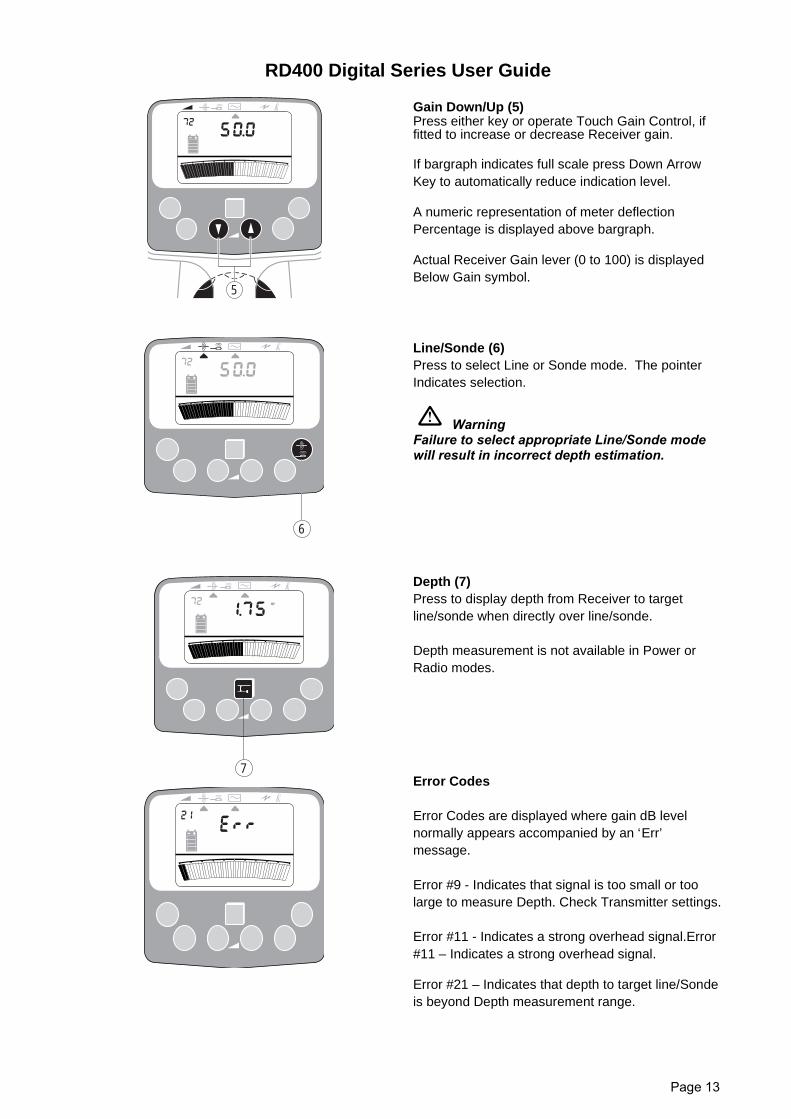
Gain Down/Up (5)Press either key or operate Touch Gain Control, iffitted to increase or decrease Receiver gain.
If bargraph indicates full scale press Down ArrowKey to automatically reduce indication level.
A numeric representation of meter deflectionPercentage is displayed above bargraph.
Actual Receiver Gain lever (0 to 100) is displayedBelow Gain symbol.
Line/Sonde (6)Press to select Line or Sonde mode. The pointerIndicates selection.
WarningFailure to select appropriate Line/Sonde modewill result in incorrect depth estimation.
Depth (7)Press to display depth from Receiver to targetline/sonde when directly over line/sonde.
Depth measurement is not available in Power orRadio modes.
Error Codes
Error Codes are displayed where gain dB levelnormally appears accompanied by an ‘Err’message.
Error #9 - Indicates that signal is too small or toolarge to measure Depth. Check Transmitter settings.
Error #11 - Indicates a strong overhead signal.Error#11 – Indicates a strong overhead signal.
Error #21 – Indicates that depth to target line/Sondeis beyond Depth measurement range.
5
6
7
m

RD400 Digital Series User Guide
Page 14
RD400 Digital Series User Guide
Page 15
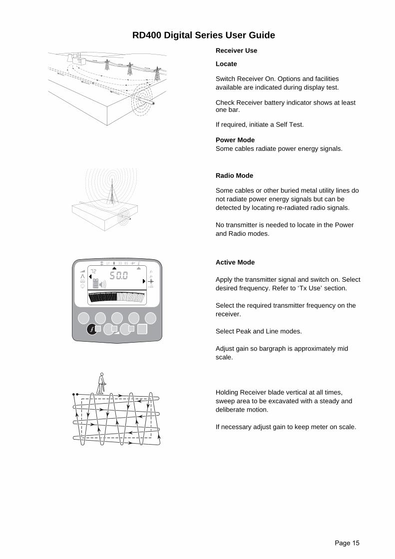
Receiver Use
Locate
Switch Receiver On. Options and facilitiesavailable are indicated during display test.
Check Receiver battery indicator shows at leastone bar.
If required, initiate a Self Test.
Power ModeSome cables radiate power energy signals.
Radio Mode
Some cables or other buried metal utility lines donot radiate power energy signals but can bedetected by locating re-radiated radio signals.
No transmitter is needed to locate in the Powerand Radio modes.
Active Mode
Apply the transmitter signal and switch on. Selectdesired frequency. Refer to ‘Tx Use’ section.
Select the required transmitter frequency on thereceiver.
Select Peak and Line modes.
Adjust gain so bargraph is approximately midscale.
Holding Receiver blade vertical at all times,sweep area to be excavated with a steady anddeliberate motion.
If necessary adjust gain to keep meter on scale.
8 33 65Lf
1
2
RD400 Digital Series User Guide
Page 16
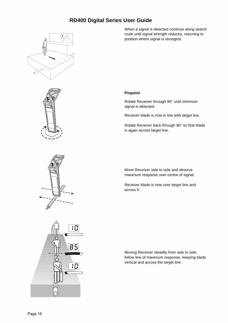
When a signal is detected continue along searchroute until signal strength reduces, returning toposition where signal is strongest.
Pinpoint
Rotate Receiver through 90° until minimumsignal is detected.
Receiver blade is now in line with target line.
Rotate Receiver back through 90° so that bladeis again across target line.
Move Receiver side to side and observemaximum response over centre of signal.
Receiver blade is now over target line andacross it.
Moving Receiver steadily from side to side,follow line of maximum response, keeping bladevertical and across the target line.
RD400 Digital Series User Guide
Page 17
Mark target line position with chalk or paint.
Continue sweeping the area, following gridpattern.
Null
Select Null mode.
Walk along path of target line. Minimumresponse with an increased response each sideindicates position of target line.
When the Receiver blade is across the targetline, on some receivers, the Left/Right arrows ondisplay will point in the direction of the targetline.
Stop every 10 - 20 paces and check position.Periodically switch back to Peak to confirmposition.
Note:Although the Peak position of a line is moredifficult to identify, it is usually more accuratethan the Null position.
Depth Reading to a Line
Depth readings can only be accurately performedwhen using the active transmitter mode.
Pinpoint target line as previously described. HoldReceiver vertically with blade resting on theground.
Ensure Line mode is selected.Momentarily pressthe Depth key. Depth reading isdisplayed for afew seconds.
WarningCertain conditions can cause depth errors.
8 33 65Lf
1
2
d
RD400 Digital Series User Guide
Page 18
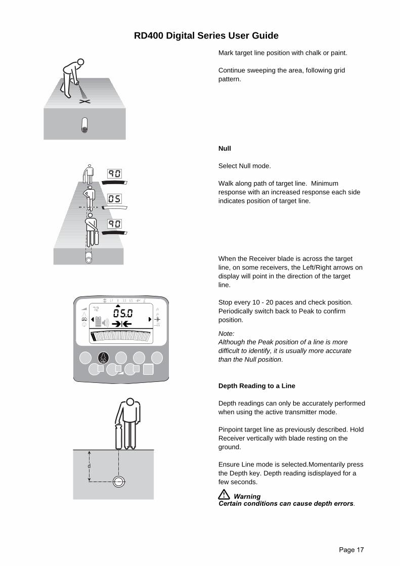
Depth in Power Mode
As current on power cables may fluctuate Depthreadings in Power mode are NOT as reliable asactive transmitter Depth measurements.
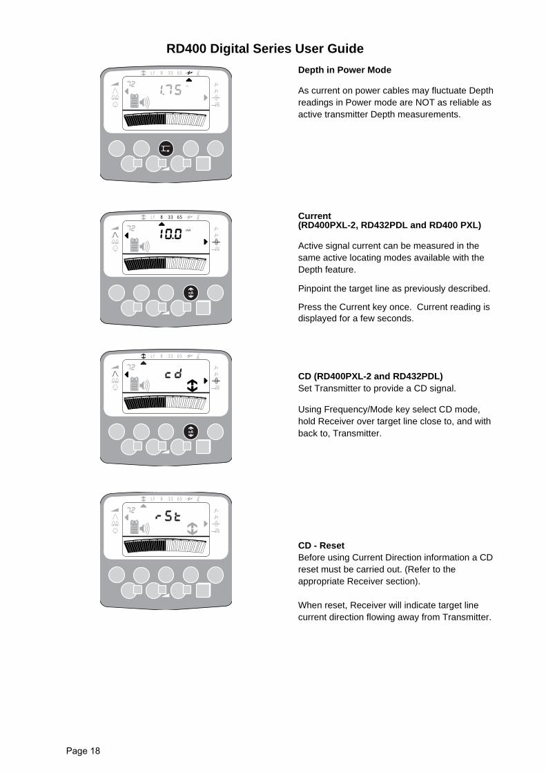
Current(RD400PXL-2, RD432PDL and RD400 PXL)
Active signal current can be measured in thesame active locating modes available with theDepth feature.
Pinpoint the target line as previously described.
Press the Current key once. Current reading isdisplayed for a few seconds.
CD (RD400PXL-2 and RD432PDL)Set Transmitter to provide a CD signal.
Using Frequency/Mode key select CD mode,hold Receiver over target line close to, and withback to, Transmitter.
CD - ResetBefore using Current Direction information a CDreset must be carried out. (Refer to theappropriate Receiver section).
When reset, Receiver will indicate target linecurrent direction flowing away from Transmitter.
8 33 65Lf
1
2
m
8 33 65Lf
1
2
mA
8 33 65Lf
1
2
8 33 65Lf
1
2
RD400 Digital Series User Guide
Page 19
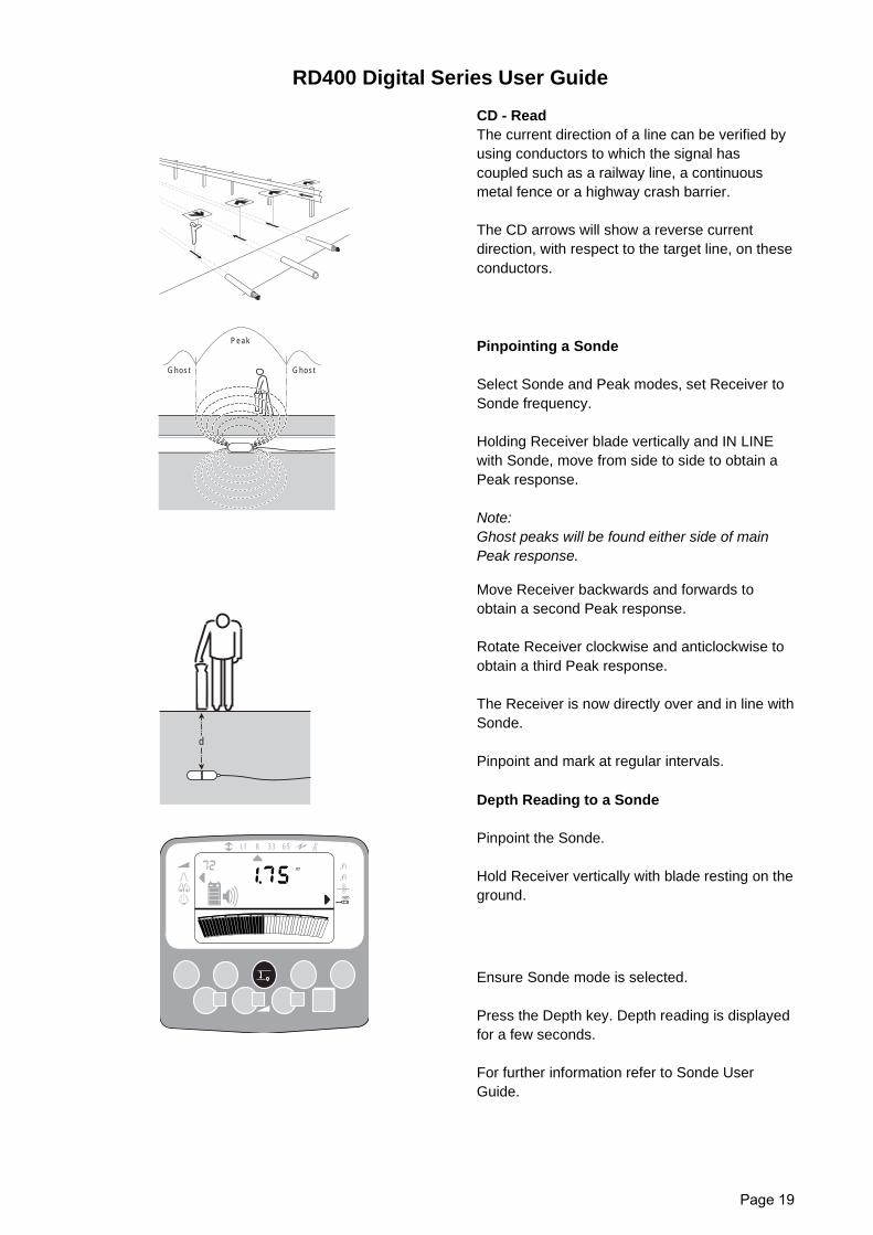
CD - ReadThe current direction of a line can be verified byusing conductors to which the signal hascoupled such as a railway line, a continuousmetal fence or a highway crash barrier.
The CD arrows will show a reverse currentdirection, with respect to the target line, on theseconductors.
Pinpointing a Sonde
Select Sonde and Peak modes, set Receiver toSonde frequency.
Holding Receiver blade vertically and IN LINEwith Sonde, move from side to side to obtain aPeak response.
Note:Ghost peaks will be found either side of mainPeak response.
Move Receiver backwards and forwards toobtain a second Peak response.
Rotate Receiver clockwise and anticlockwise toobtain a third Peak response.
The Receiver is now directly over and in line withSonde.
Pinpoint and mark at regular intervals.
Depth Reading to a Sonde
Pinpoint the Sonde.
Hold Receiver vertically with blade resting on theground.
Ensure Sonde mode is selected.
Press the Depth key. Depth reading is displayedfor a few seconds.
For further information refer to Sonde UserGuide.
Peak
Ghost Ghost
d
8 33 65Lf
1
2
m
RD400 Digital Series User Guide
Page 20
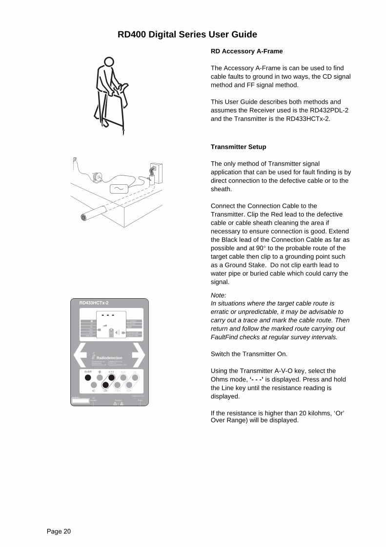
RD Accessory A-Frame
The Accessory A-Frame is can be used to findcable faults to ground in two ways, the CD signalmethod and FF signal method.
This User Guide describes both methods andassumes the Receiver used is the RD432PDL-2and the Transmitter is the RD433HCTx-2.
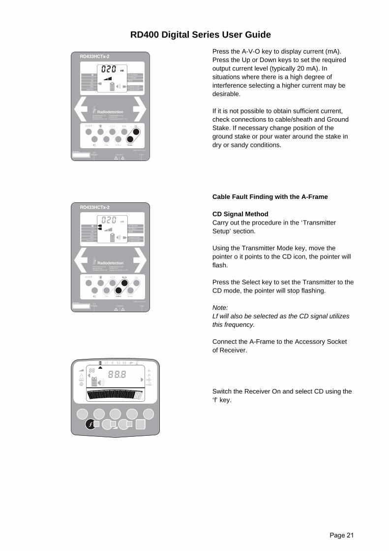
Transmitter Setup
The only method of Transmitter signalapplication that can be used for fault finding is bydirect connection to the defective cable or to thesheath.
Connect the Connection Cable to theTransmitter. Clip the Red lead to the defectivecable or cable sheath cleaning the area ifnecessary to ensure connection is good. Extendthe Black lead of the Connection Cable as far aspossible and at 90° to the probable route of thetarget cable then clip to a grounding point suchas a Ground Stake. Do not clip earth lead towater pipe or buried cable which could carry thesignal.
Note:In situations where the target cable route iserratic or unpredictable, it may be advisable tocarry out a trace and mark the cable route. Thenreturn and follow the marked route carrying outFaultFind checks at regular survey intervals.
Switch the Transmitter On.
Using the Transmitter A-V-O key, select theOhms mode, ‘- - -’ is displayed. Press and holdthe Line key until the resistance reading isdisplayed.
If the resistance is higher than 20 kilohms, ‘Or’Over Range) will be displayed.
On/Off A-V-O Up
Line Select
Mode
Down
FF Normal
FF Boost
Connect 24V
Connect 50V
Lf
8k
33k
65k
User Hz
Multi
Radiodetection Corp.PO Box 623Ridgewood, NJ07451, USA
RadiodetectionRadiodetection Ltd.Western DriveBristol BS14 0AZ, UK
01/MH1054L1ENG/3
Connect Fuse12V
Adaptor
Serial No.
RD400 Digital Series User Guide
Page 21
Press the A-V-O key to display current (mA).Press the Up or Down keys to set the requiredoutput current level (typically 20 mA). Insituations where there is a high degree ofinterference selecting a higher current may bedesirable.
If it is not possible to obtain sufficient current,check connections to cable/sheath and GroundStake. If necessary change position of theground stake or pour water around the stake indry or sandy conditions.
Cable Fault Finding with the A-Frame
CD Signal MethodCarry out the procedure in the ‘TransmitterSetup’ section.
Using the Transmitter Mode key, move thepointer o it points to the CD icon, the pointer willflash.
Press the Select key to set the Transmitter to theCD mode, the pointer will stop flashing.
Note:Lf will also be selected as the CD signal utilizesthis frequency.
Connect the A-Frame to the Accessory Socketof Receiver.
Switch the Receiver On and select CD using the‘f’ key.
On/Off A-V-O Up
Line Select
Mode
Down
FF Normal
FF Boost
Connect 24V
Connect 50V
Lf
8k
33k
65k
User Hz
Multi
mA
Radiodetection Corp.PO Box 623Ridgewood, NJ07451, USA
RadiodetectionRadiodetection Ltd.Western DriveBristol BS14 0AZ, UK
01/MH1054L1ENG/3
Connect Fuse12V
Adaptor
Serial No.
On/Off A-V-O Up
Line Select
Mode
Down
FF Normal
FF Boost
Connect 24V
Connect 50V
Lf
8k
33k
65k
User Hz
Multi
mA
Radiodetection Corp.PO Box 623Ridgewood, NJ07451, USA
RadiodetectionRadiodetection Ltd.Western DriveBristol BS14 0AZ, UK
01/MH1054L1ENG/3
Connect Fuse12V
Adaptor
Serial No.
8 33 65Lf
a
b
RD400 Digital Series User Guide
Page 22
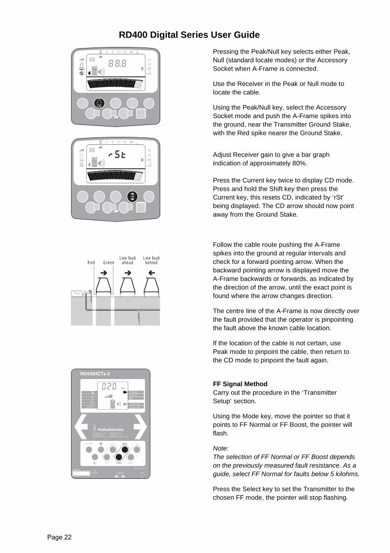
Pressing the Peak/Null key selects either Peak,Null (standard locate modes) or the AccessorySocket when A-Frame is connected.
Use the Receiver in the Peak or Null mode tolocate the cable.
Using the Peak/Null key, select the AccessorySocket mode and push the A-Frame spikes intothe ground, near the Transmitter Ground Stake,with the Red spike nearer the Ground Stake.
Adjust Receiver gain to give a bar graphindication of approximately 80%.
Press the Current key twice to display CD mode.Press and hold the Shift key then press theCurrent key, this resets CD, indicated by ‘rSt’being displayed. The CD arrow should now pointaway from the Ground Stake.
Follow the cable route pushing the A-Framespikes into the ground at regular intervals andcheck for a forward pointing arrow. When thebackward pointing arrow is displayed move theA-Frame backwards or forwards, as indicated bythe direction of the arrow, until the exact point isfound where the arrow changes direction.
The centre line of the A-Frame is now directly overthe fault provided that the operator is pinpointingthe fault above the known cable location.
If the location of the cable is not certain, usePeak mode to pinpoint the cable, then return tothe CD mode to pinpoint the fault again.
FF Signal MethodCarry out the procedure in the ‘TransmitterSetup’ section.
Using the Mode key, move the pointer so that itpoints to FF Normal or FF Boost, the pointer willflash.
Note:The selection of FF Normal or FF Boost dependson the previously measured fault resistance. As aguide, select FF Normal for faults below 5 kilohms.
Press the Select key to set the Transmitter to thechosen FF mode, the pointer will stop flashing.
8 33 65Lf
a
b
8 33 65Lf
a
b
RedLine fault
aheadLine faultbehindGreen
On/Off A-V-O Up
Line Select
Mode
Down
FF Normal
FF Boost
Connect 24V
Connect 50V
Lf
8k
33k
65k
User Hz
Multi
mA
Radiodetection Corp.PO Box 623Ridgewood, NJ07451, USA
RadiodetectionRadiodetection Ltd.Western DriveBristol BS14 0AZ, UK
01/MH1054L1ENG/3
Connect Fuse12V
Adaptor
Serial No.
RD400 Digital Series User Guide
Page 23
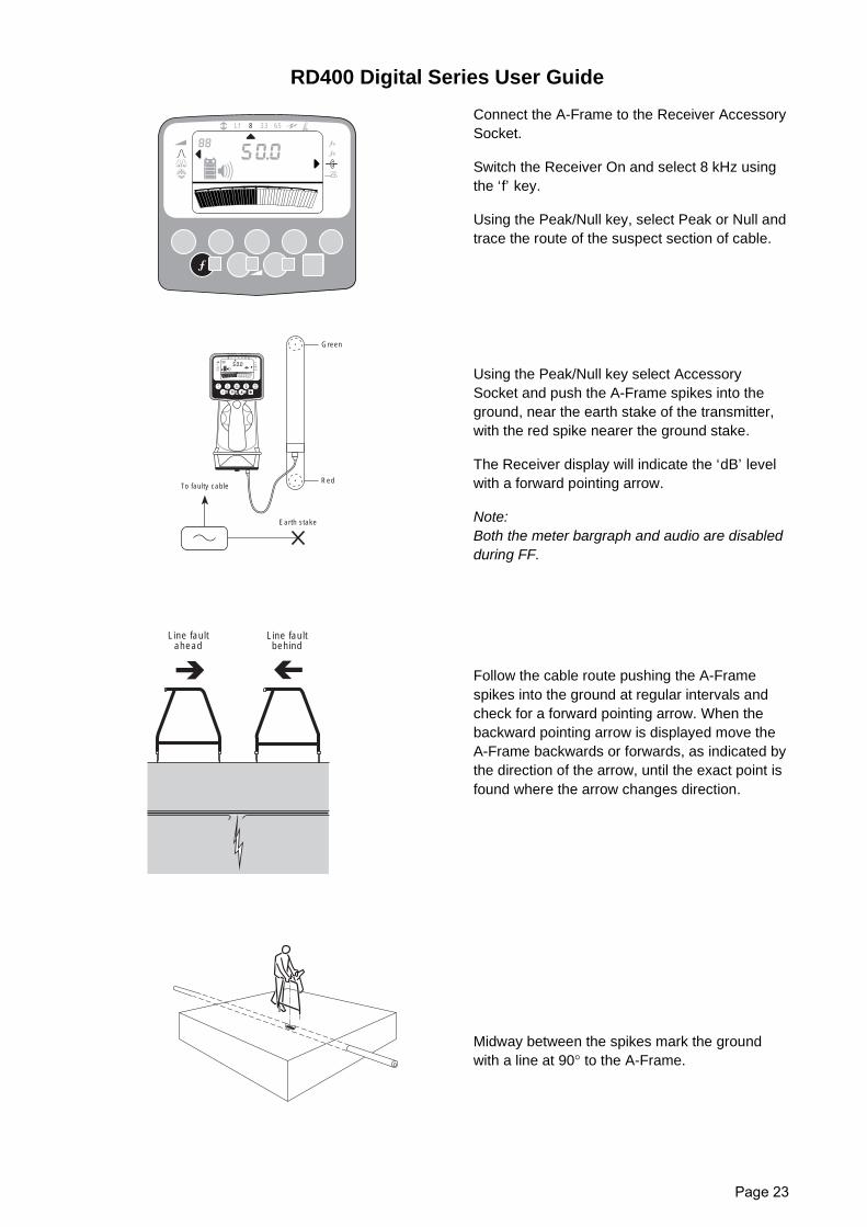
Connect the A-Frame to the Receiver AccessorySocket.
Switch the Receiver On and select 8 kHz usingthe ‘f’ key.
Using the Peak/Null key, select Peak or Null andtrace the route of the suspect section of cable.
Using the Peak/Null key select AccessorySocket and push the A-Frame spikes into theground, near the earth stake of the transmitter,with the red spike nearer the ground stake.
The Receiver display will indicate the ‘dB’ levelwith a forward pointing arrow.
Note:Both the meter bargraph and audio are disabledduring FF.
Follow the cable route pushing the A-Framespikes into the ground at regular intervals andcheck for a forward pointing arrow. When thebackward pointing arrow is displayed move theA-Frame backwards or forwards, as indicated bythe direction of the arrow, until the exact point isfound where the arrow changes direction.
Midway between the spikes mark the groundwith a line at 90° to the A-Frame.
8 33 65Lf
a
b
8 33 65Lf
1
2
To faulty cable
Green
Red
Earth stake
Line faultahead
Line faultbehind
RD400 Digital Series User Guide
Page 24
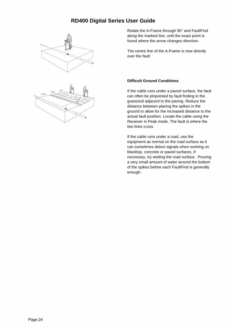
Rotate the A-Frame through 90° and FaultFindalong the marked line, until the exact point isfound where the arrow changes direction.
The centre line of the A-Frame is now directlyover the fault.
Difficult Ground Conditions
If the cable runs under a paved surface, the faultcan often be pinpointed by fault finding in thegrass/soil adjacent to the paving. Reduce thedistance between placing the spikes in theground to allow for the increased distance to theactual fault position. Locate the cable using theReceiver in Peak mode. The fault is where thetwo lines cross.
If the cable runs under a road, use theequipment as normal on the road surface as itcan sometimes detect signals when working onblacktop, concrete or paved surfaces. Ifnecessary, try wetting the road surface. Pouringa very small amount of water around the bottomof the spikes before each FaultFind is generallyenough.
RoadPath
Soil
Faultline
RD400 Digital Series User Guide
Page 25
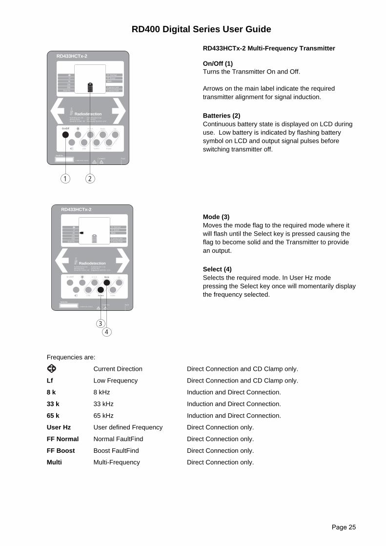
RD433HCTx-2 Multi-Frequency Transmitter
On/Off (1)Turns the Transmitter On and Off.
Arrows on the main label indicate the requiredtransmitter alignment for signal induction.
Batteries (2)Continuous battery state is displayed on LCD duringuse. Low battery is indicated by flashing batterysymbol on LCD and output signal pulses beforeswitching transmitter off.
Mode (3)Moves the mode flag to the required mode where itwill flash until the Select key is pressed causing theflag to become solid and the Transmitter to providean output.
Select (4)Selects the required mode. In User Hz modepressing the Select key once will momentarily displaythe frequency selected.
Frequencies are:
Current Direction Direct Connection and CD Clamp only.
Lf Low Frequency Direct Connection and CD Clamp only.
8 k 8 kHz Induction and Direct Connection.
33 k 33 kHz Induction and Direct Connection.
65 k 65 kHz Induction and Direct Connection.
User Hz User defined Frequency Direct Connection only.
FF Normal Normal FaultFind Direct Connection only.
FF Boost Boost FaultFind Direct Connection only.
Multi Multi-Frequency Direct Connection only.
On/Off A-V-O Up
Line Select
Mode
Down
FF Normal
FF Boost
Connect 24V
Connect 50V
Connect Fuse
Lf
8k
33k
65k
User Hz
01/MH1054L1ENG/2
RD433HCTx-2
Multi
1 2
Radiodetection Corp.PO Box 623Ridgewood, NJ07451, USA
Serial No.
RadiodetectionRadiodetection Ltd.Western DriveBristol BS14 0AZ, UK
On/Off A-V-O Up
Line Select
Mode
Down
FF Normal
FF Boost
Connect 24V
Connect 50V
Connect Fuse
Lf
8k
33k
65k
User Hz
01/MH1054L1ENG/2
RD433HCTx-2
Multi
34
Radiodetection Corp.PO Box 623Ridgewood, NJ07451, USA
Serial No.
RadiodetectionRadiodetection Ltd.Western DriveBristol BS14 0AZ, UK
RD400 Digital Series User Guide
Page 26
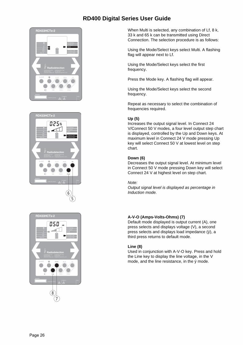
When Multi is selected, any combination of Lf, 8 k,33 k and 65 k can be transmitted using DirectConnection. The selection procedure is as follows:
Using the Mode/Select keys select Multi. A flashingflag will appear next to Lf.
Using the Mode/Select keys select the firstfrequency.
Press the Mode key. A flashing flag will appear.
Using the Mode/Select keys select the secondfrequency.
Repeat as necessary to select the combination offrequencies required.
Up (5) Increases the output signal level. In Connect 24V/Connect 50 V modes, a four level output step chartis displayed, controlled by the Up and Down keys. Atmaximum level in Connect 24 V mode pressing Upkey will select Connect 50 V at lowest level on stepchart.
Down (6)Decreases the output signal level. At minimum levelin Connect 50 V mode pressing Down key will selectConnect 24 V at highest level on step chart.
Note:Output signal level is displayed as percentage inInduction mode.
A-V-O (Amps-Volts-Ohms) (7)Default mode displayed is output current (A), onepress selects and displays voltage (V), a secondpress selects and displays load impedance (ý), athird press returns to default mode.
Line (8)Used in conjunction with A-V-O key. Press and holdthe Line key to display the line voltage, in the Vmode, and the line resistance, in the ý mode.
On/Off A-V-O Up
Line Select
Mode
Down
FF Normal
FF Boost
Connect 24V
Connect 50V
Connect Fuse
Lf
8k
33k
65k
User Hz
01/MH1054L1ENG/2
Multi
Radiodetection Corp.PO Box 623Ridgewood, NJ07451, USA
Serial No.
RadiodetectionRadiodetection Ltd.Western DriveBristol BS14 0AZ, UK
On/Off A-V-O Up
Line Select
Mode
Down
FF Normal
FF Boost
Connect 24V
Connect 50V
Connect Fuse
Lf
8k
33k
65k
User Hz
01/MH1054L1ENG/2
Multi
65
%
Radiodetection Corp.PO Box 623Ridgewood, NJ07451, USA
Serial No.
RadiodetectionRadiodetection Ltd.Western DriveBristol BS14 0AZ, UK
On/Off A-V-O Up
Line Select
Mode
Down
FF Normal
FF Boost
Connect 24V
Connect 50V
Connect Fuse
Lf
8k
33k
65k
User Hz
01/MH1054L1ENG/2
Multi
87
kΩHzmAV
Radiodetection Corp.PO Box 623Ridgewood, NJ07451, USA
Serial No.
RadiodetectionRadiodetection Ltd.Western DriveBristol BS14 0AZ, UK
RD400 Digital Series User Guide
Page 27
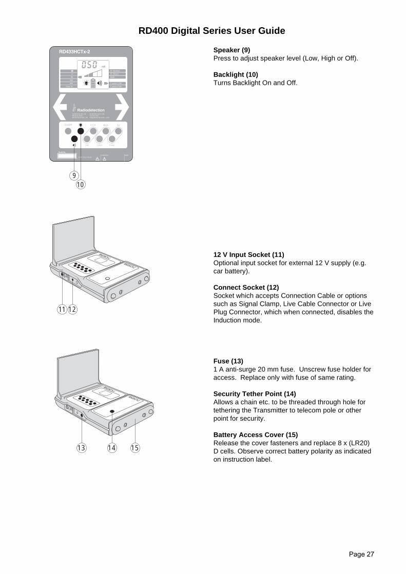
Speaker (9)Press to adjust speaker level (Low, High or Off).
Backlight (10)Turns Backlight On and Off.
12 V Input Socket (11)Optional input socket for external 12 V supply (e.g.car battery).
Connect Socket (12)Socket which accepts Connection Cable or optionssuch as Signal Clamp, Live Cable Connector or LivePlug Connector, which when connected, disables theInduction mode.
Fuse (13)1 A anti-surge 20 mm fuse. Unscrew fuse holder foraccess. Replace only with fuse of same rating.
Security Tether Point (14)Allows a chain etc. to be threaded through hole fortethering the Transmitter to telecom pole or otherpoint for security.
Battery Access Cover (15)Release the cover fasteners and replace 8 x (LR20)D cells. Observe correct battery polarity as indicatedon instruction label.
On/Off A-V-O Up
Line Select
Mode
Down
FF Normal
FF Boost
Connect 24V
Connect 50V
Connect Fuse
Lf
8k
33k
65k
User Hz
01/MH1054L1ENG/2
Multi
kΩHzmAV
910
Radiodetection Corp.PO Box 623Ridgewood, NJ07451, USA
Serial No.
RadiodetectionRadiodetection Ltd.Western DriveBristol BS14 0AZ, UK
RD433HCTx-2
RD433HCTx-2
1211
RD433HCTx-2
RD433HCTx-2
13 1514
RD400 Digital Series User Guide
Page 28
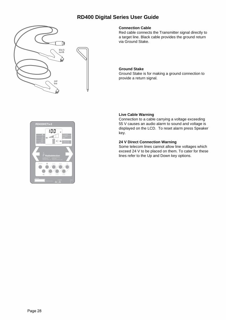
Connection CableRed cable connects the Transmitter signal directly toa target line. Black cable provides the ground returnvia Ground Stake.
Ground StakeGround Stake is for making a ground connection toprovide a return signal.
Live Cable WarningConnection to a cable carrying a voltage exceeding55 V causes an audio alarm to sound and voltage isdisplayed on the LCD. To reset alarm press Speakerkey.
24 V Direct Connection WarningSome telecom lines cannot allow line voltages whichexceed 24 V to be placed on them. To cater for theselines refer to the Up and Down key options.
blackearth
redlive
On/Off A-V-O Up
Line Select
Mode
Down
FF Normal
FF Boost
Connect 24V
Connect 50V
Connect Fuse
Lf
8k
33k
65k
User Hz
01/MH1054L1ENG/2
Multi
kΩHzmAV
Radiodetection Corp.PO Box 623Ridgewood, NJ07451, USA
Serial No.
RadiodetectionRadiodetection Ltd.Western DriveBristol BS14 0AZ, UK
RD400 Digital Series User Guide
Page 29
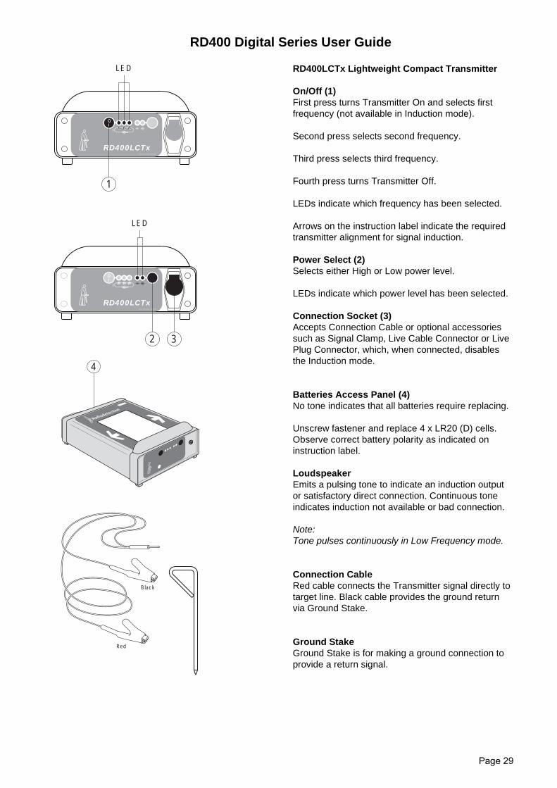
RD400LCTx Lightweight Compact Transmitter
On/Off (1)First press turns Transmitter On and selects firstfrequency (not available in Induction mode).
Second press selects second frequency.
Third press selects third frequency.
Fourth press turns Transmitter Off.
LEDs indicate which frequency has been selected.
Arrows on the instruction label indicate the requiredtransmitter alignment for signal induction.
Power Select (2)Selects either High or Low power level.
LEDs indicate which power level has been selected.
Connection Socket (3)Accepts Connection Cable or optional accessoriessuch as Signal Clamp, Live Cable Connector or LivePlug Connector, which, when connected, disablesthe Induction mode.
Batteries Access Panel (4)No tone indicates that all batteries require replacing.
Unscrew fastener and replace 4 x LR20 (D) cells.Observe correct battery polarity as indicated oninstruction label.
LoudspeakerEmits a pulsing tone to indicate an induction outputor satisfactory direct connection. Continuous toneindicates induction not available or bad connection.
Note:Tone pulses continuously in Low Frequency mode.
Connection CableRed cable connects the Transmitter signal directly totarget line. Black cable provides the ground returnvia Ground Stake.
Ground StakeGround Stake is for making a ground connection toprovide a return signal.
RD400LCTx01/LX1337L1INT/0
1
LED
321
RD400LCTx01/LX1337L1INT/0
LED
2 3
321
RD400LCTx
Rad iod etection
4
Red
Black
RD400 Digital Series User Guide
Page 30
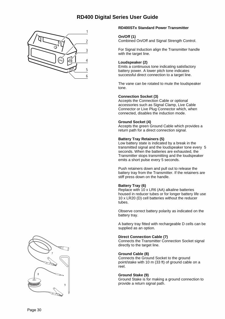
RD400STx Standard Power Transmitter
On/Off (1)Combined On/Off and Signal Strength Control.
For Signal Induction align the Transmitter handlewith the target line.
Loudspeaker (2)Emits a continuous tone indicating satisfactorybattery power. A lower pitch tone indicatessuccessful direct connection to a target line.
The vane can be rotated to mute the loudspeakertone.
Connection Socket (3)Accepts the Connection Cable or optionalaccessories such as Signal Clamp, Live CableConnector or Live Plug Connector which, whenconnected, disables the induction mode.
Ground Socket (4)Accepts the green Ground Cable which provides areturn path for a direct connection signal.
Battery Tray Retainers (5)Low battery state is indicated by a break in thetransmitted signal and the loudspeaker tone every 5seconds. When the batteries are exhausted, theTransmitter stops transmitting and the loudspeakeremits a short pulse every 5 seconds.
Push retainers down and pull out to release thebattery tray from the Transmitter. If the retainers arestiff press down on the handle.
Battery Tray (6)Replace with 10 x LR6 (AA) alkaline batterieshoused in reducer tubes or for longer battery life use10 x LR20 (D) cell batteries without the reducertubes.
Observe correct battery polarity as indicated on thebattery tray.
A battery tray fitted with rechargeable D cells can besupplied as an option.
Direct Connection Cable (7)Connects the Transmitter Connection Socket signaldirectly to the target line.
Ground Cable (8)Connects the Ground Socket to the groundpoint/stake with 10 m (33 ft) of ground cable on areel.
Ground Stake (9)Ground Stake is for making a ground connection toprovide a return signal path.
1
2
3
4
5
6
7
8
9
RD400 Digital Series User Guide
Page 31
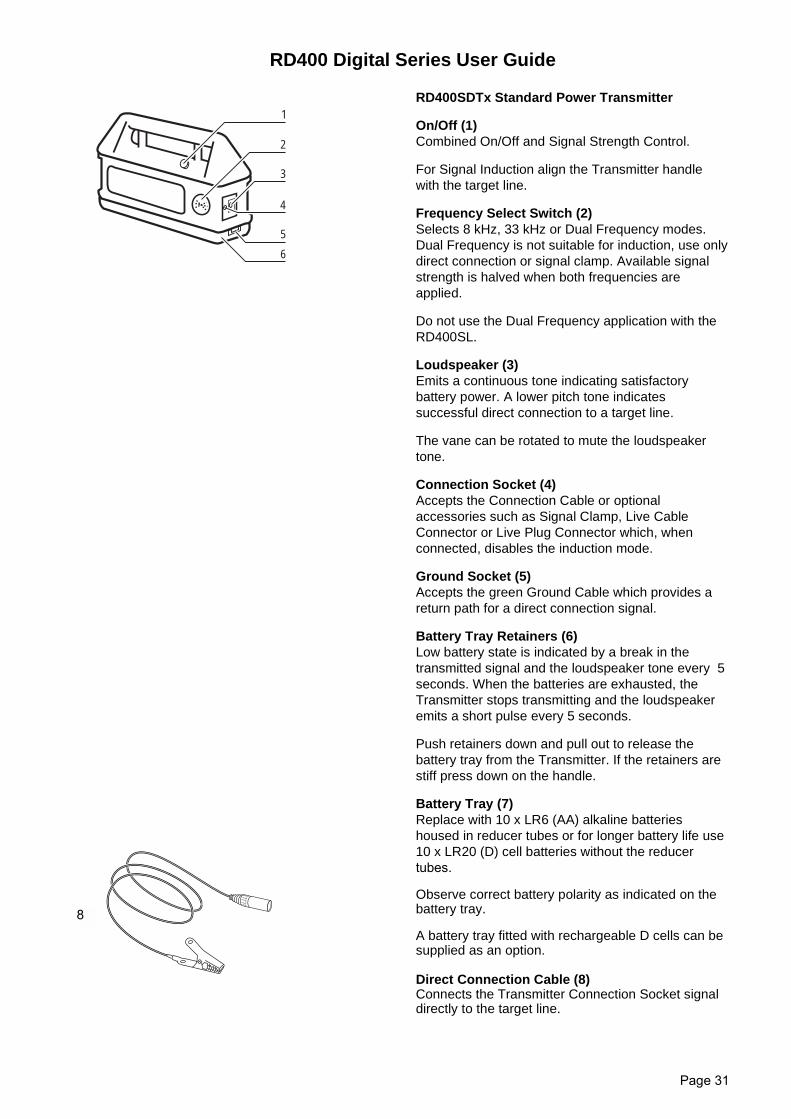
RD400SDTx Standard Power Transmitter
On/Off (1)Combined On/Off and Signal Strength Control.
For Signal Induction align the Transmitter handlewith the target line.
Frequency Select Switch (2)Selects 8 kHz, 33 kHz or Dual Frequency modes.Dual Frequency is not suitable for induction, use onlydirect connection or signal clamp. Available signalstrength is halved when both frequencies areapplied.
Do not use the Dual Frequency application with theRD400SL.
Loudspeaker (3)Emits a continuous tone indicating satisfactorybattery power. A lower pitch tone indicatessuccessful direct connection to a target line.
The vane can be rotated to mute the loudspeakertone.
Connection Socket (4)Accepts the Connection Cable or optionalaccessories such as Signal Clamp, Live CableConnector or Live Plug Connector which, whenconnected, disables the induction mode.
Ground Socket (5)Accepts the green Ground Cable which provides areturn path for a direct connection signal.
Battery Tray Retainers (6)Low battery state is indicated by a break in thetransmitted signal and the loudspeaker tone every 5seconds. When the batteries are exhausted, theTransmitter stops transmitting and the loudspeakeremits a short pulse every 5 seconds.
Push retainers down and pull out to release thebattery tray from the Transmitter. If the retainers arestiff press down on the handle.
Battery Tray (7)Replace with 10 x LR6 (AA) alkaline batterieshoused in reducer tubes or for longer battery life use10 x LR20 (D) cell batteries without the reducertubes.
Observe correct battery polarity as indicated on thebattery tray.
A battery tray fitted with rechargeable D cells can besupplied as an option.
Direct Connection Cable (8)Connects the Transmitter Connection Socket signaldirectly to the target line.
1
2
3
4
5
6
8
RD400 Digital Series User Guide
Page 32
Ground Cable (9)Connects the Ground Socket to the groundpoint/stake with 10 m (33 ft) of ground cable on areel.
Ground Stake (10)Ground Stake is for making a ground connection toprovide a return signal path.
9
10
RD400 Digital Series User Guide
Page 33
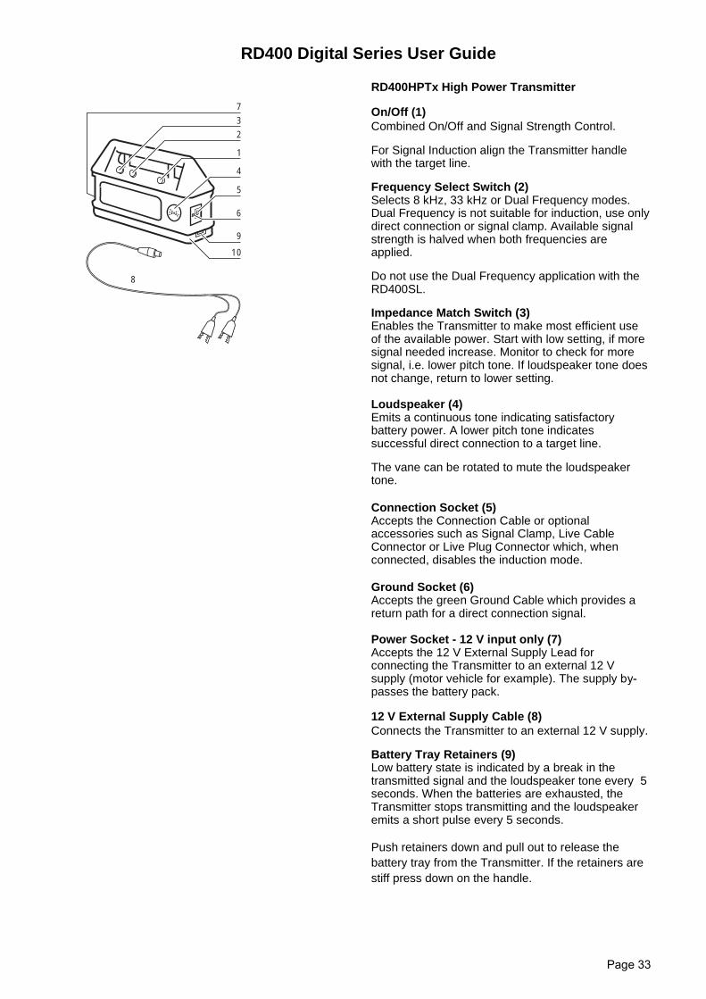
RD400HPTx High Power Transmitter
On/Off (1)Combined On/Off and Signal Strength Control.
For Signal Induction align the Transmitter handlewith the target line.
Frequency Select Switch (2)Selects 8 kHz, 33 kHz or Dual Frequency modes.Dual Frequency is not suitable for induction, use onlydirect connection or signal clamp. Available signalstrength is halved when both frequencies areapplied.
Do not use the Dual Frequency application with theRD400SL.
Impedance Match Switch (3)Enables the Transmitter to make most efficient useof the available power. Start with low setting, if moresignal needed increase. Monitor to check for moresignal, i.e. lower pitch tone. If loudspeaker tone doesnot change, return to lower setting.
Loudspeaker (4)Emits a continuous tone indicating satisfactorybattery power. A lower pitch tone indicatessuccessful direct connection to a target line.
The vane can be rotated to mute the loudspeakertone.
Connection Socket (5)Accepts the Connection Cable or optionalaccessories such as Signal Clamp, Live CableConnector or Live Plug Connector which, whenconnected, disables the induction mode.
Ground Socket (6)Accepts the green Ground Cable which provides areturn path for a direct connection signal.
Power Socket - 12 V input only (7)Accepts the 12 V External Supply Lead forconnecting the Transmitter to an external 12 Vsupply (motor vehicle for example). The supply by-passes the battery pack.
12 V External Supply Cable (8)Connects the Transmitter to an external 12 V supply.
Battery Tray Retainers (9)Low battery state is indicated by a break in thetransmitted signal and the loudspeaker tone every 5seconds. When the batteries are exhausted, theTransmitter stops transmitting and the loudspeakeremits a short pulse every 5 seconds.
Push retainers down and pull out to release thebattery tray from the Transmitter. If the retainers arestiff press down on the handle.
1
4
5
6
9
10
2
3
7
8
RD400 Digital Series User Guide
Page 34
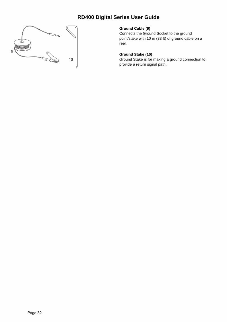
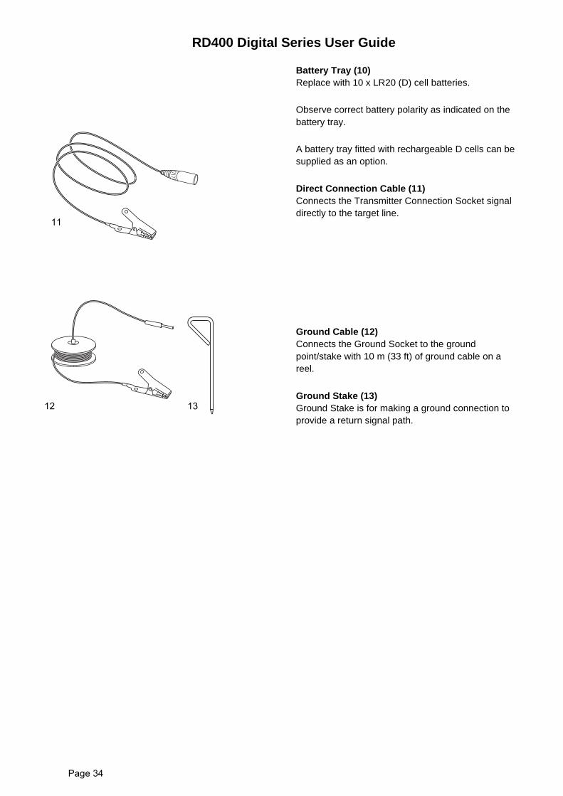
Battery Tray (10)Replace with 10 x LR20 (D) cell batteries.
Observe correct battery polarity as indicated on thebattery tray.
A battery tray fitted with rechargeable D cells can besupplied as an option.
Direct Connection Cable (11)Connects the Transmitter Connection Socket signaldirectly to the target line.
Ground Cable (12)Connects the Ground Socket to the groundpoint/stake with 10 m (33 ft) of ground cable on areel.
Ground Stake (13)Ground Stake is for making a ground connection toprovide a return signal path.
11
12 13
RD400 Digital Series User Guide
Page 35
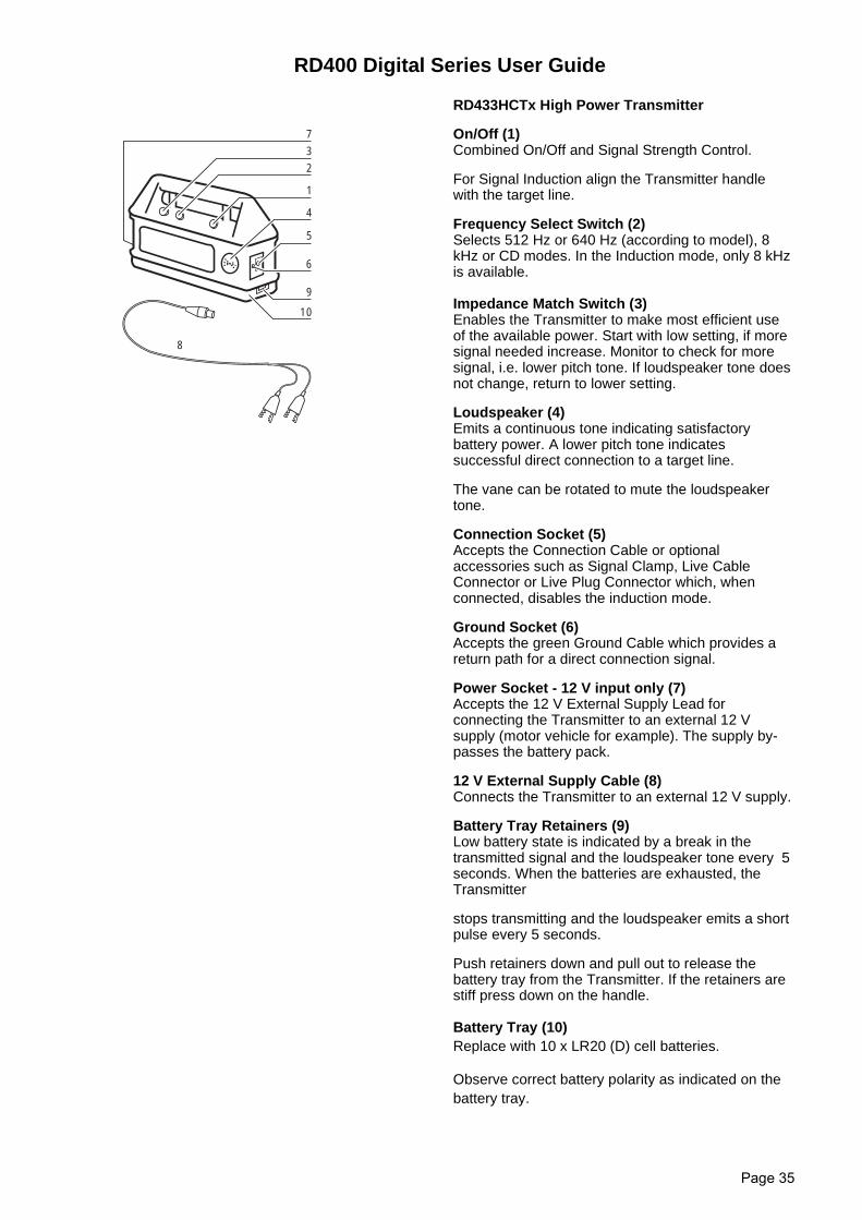
RD433HCTx High Power Transmitter
On/Off (1) Combined On/Off and Signal Strength Control.
For Signal Induction align the Transmitter handlewith the target line.
Frequency Select Switch (2)Selects 512 Hz or 640 Hz (according to model), 8kHz or CD modes. In the Induction mode, only 8 kHzis available.
Impedance Match Switch (3)Enables the Transmitter to make most efficient useof the available power. Start with low setting, if moresignal needed increase. Monitor to check for moresignal, i.e. lower pitch tone. If loudspeaker tone doesnot change, return to lower setting.
Loudspeaker (4)Emits a continuous tone indicating satisfactorybattery power. A lower pitch tone indicatessuccessful direct connection to a target line.
The vane can be rotated to mute the loudspeakertone.
Connection Socket (5)Accepts the Connection Cable or optionalaccessories such as Signal Clamp, Live CableConnector or Live Plug Connector which, whenconnected, disables the induction mode.
Ground Socket (6)Accepts the green Ground Cable which provides areturn path for a direct connection signal.
Power Socket - 12 V input only (7)Accepts the 12 V External Supply Lead forconnecting the Transmitter to an external 12 Vsupply (motor vehicle for example). The supply by-passes the battery pack.
12 V External Supply Cable (8)Connects the Transmitter to an external 12 V supply.
Battery Tray Retainers (9)Low battery state is indicated by a break in thetransmitted signal and the loudspeaker tone every 5seconds. When the batteries are exhausted, theTransmitter
stops transmitting and the loudspeaker emits a shortpulse every 5 seconds.
Push retainers down and pull out to release thebattery tray from the Transmitter. If the retainers arestiff press down on the handle.
Battery Tray (10)Replace with 10 x LR20 (D) cell batteries.
Observe correct battery polarity as indicated on thebattery tray.
1
4
5
6
9
10
2
3
7
8
RD400 Digital Series User Guide
Page 36
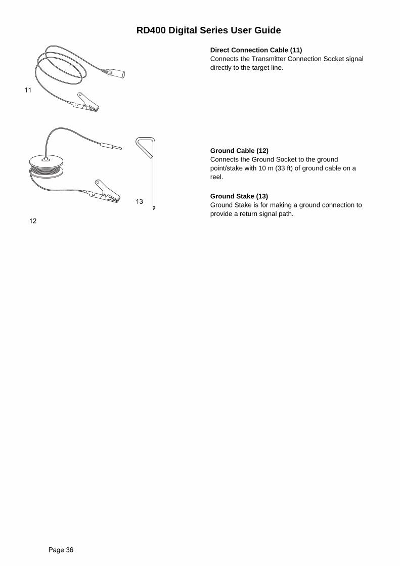
Direct Connection Cable (11)Connects the Transmitter Connection Socket signaldirectly to the target line.
Ground Cable (12)Connects the Ground Socket to the groundpoint/stake with 10 m (33 ft) of ground cable on areel.
Ground Stake (13)Ground Stake is for making a ground connection toprovide a return signal path.
11
12
13
RD400 Digital Series User Guide
Page 37
Transmitter Use
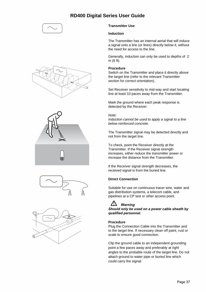
Induction
The Transmitter has an internal aerial that will inducea signal onto a line (or lines) directly below it, withoutthe need for access to the line.
Generally, induction can only be used to depths of 2m (6 ft).
ProcedureSwitch on the Transmitter and place it directly abovethe target line (refer to the relevant Transmittersection for correct orientation).
Set Receiver sensitivity to mid-way and start locatingline at least 10 paces away from the Transmitter.
Mark the ground where each peak response isdetected by the Receiver.
Note:Induction cannot be used to apply a signal to a linebelow reinforced concrete.
The Transmitter signal may be detected directly andnot from the target line.
To check, point the Receiver directly at theTransmitter. If the Receiver signal strengthincreases, either reduce the transmitter power orincrease the distance from the Transmitter.
If the Receiver signal strength decreases, thereceived signal is from the buried line.
Direct Connection
Suitable for use on continuous tracer wire, water andgas distribution systems, a telecom cable, andpipelines at a CP test or other access point.
WarningShould only be used on a power cable sheath byqualified personnel.
ProcedurePlug the Connection Cable into the Transmitter andto the target line. If necessary clean off paint, rust orscale to ensure good connection.
Clip the ground cable to an independent groundingpoint a few paces away and preferably at rightangles to the probable route of the target line. Do notattach ground to water pipe or buried line whichcould carry the signal.
RD400 Digital Series User Guide
Page 38
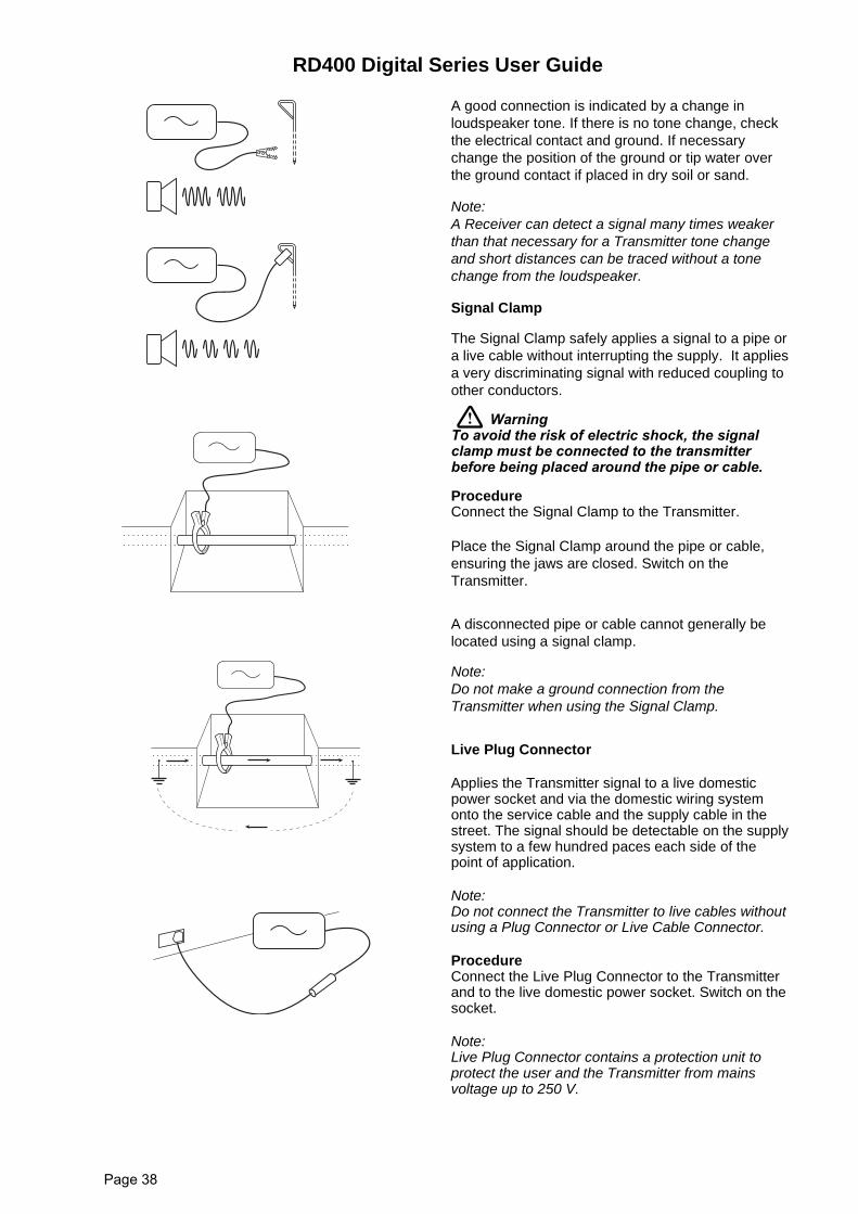
A good connection is indicated by a change inloudspeaker tone. If there is no tone change, checkthe electrical contact and ground. If necessarychange the position of the ground or tip water overthe ground contact if placed in dry soil or sand.
Note:A Receiver can detect a signal many times weakerthan that necessary for a Transmitter tone changeand short distances can be traced without a tonechange from the loudspeaker.
Signal Clamp
The Signal Clamp safely applies a signal to a pipe ora live cable without interrupting the supply. It appliesa very discriminating signal with reduced coupling toother conductors.
WarningTo avoid the risk of electric shock, the signalclamp must be connected to the transmitterbefore being placed around the pipe or cable.
ProcedureConnect the Signal Clamp to the Transmitter.
Place the Signal Clamp around the pipe or cable,ensuring the jaws are closed. Switch on theTransmitter.
A disconnected pipe or cable cannot generally belocated using a signal clamp.
Note:Do not make a ground connection from theTransmitter when using the Signal Clamp.
Live Plug Connector
Applies the Transmitter signal to a live domesticpower socket and via the domestic wiring systemonto the service cable and the supply cable in thestreet. The signal should be detectable on the supplysystem to a few hundred paces each side of thepoint of application.
Note:Do not connect the Transmitter to live cables withoutusing a Plug Connector or Live Cable Connector.
ProcedureConnect the Live Plug Connector to the Transmitterand to the live domestic power socket. Switch on thesocket.
Note:Live Plug Connector contains a protection unit toprotect the user and the Transmitter from mainsvoltage up to 250 V.

RD400 Digital Series User Guide
Page 39

RD400 Digital Series User Guide
Page 40
Radiodetection products are under continuous development andare subject to change without notice
UG09EN02
RWBTFeh
adiodetection Ltdestern Driveristol BS14 OAZ, UKel: +44 (0) 117 976 7776ax: +44 (0) 117 976 7775mail:[email protected]
All rights reservedttp://www.radiodetection.com