RC6 RC8 RC10 VW10 Vertical Rope/Chain · PDF file1 Vetus-Maxwell APAC Ltd –...
24
RC6 RC8 RC10 VW10 Vertical Rope/Chain Windlass
Transcript of RC6 RC8 RC10 VW10 Vertical Rope/Chain · PDF file1 Vetus-Maxwell APAC Ltd –...

RC6 RC8 RC10 VW10 Vertical Rope/Chain Windlass

P103123 Rev.7.00 28/06/12
Copyright Vetus-Maxwell APAC Ltd. All rights reserved.
Vetus-Maxwell APAC Ltd reserves the right to make engineering refinements on all products without notice. Always consult manual supplied with product as details may have been revised. Illustrations and specifications are not binding as to detail.
1 Vetus-Maxwell APAC Ltd – RC6/RC8/RC10/VW10 Series
INTRODUCTION • Read this manual thoroughly before installation and
using the windlass. Failure to adhere to the correct procedures, recommendations and guidelines described in this Owner’s Manual may invalidate the warranty.
• Correct selection of windlass together with correct installation, care in use and maintenance, are essential for long life and reliable performance.
• In addition to this instruction manual, the following components should be included with the windlass: • Clutch Handle • 12V or 24V reversing solenoid
(RC6, RC8 & RC10 only) • Deckplate Gasket • Deck Cutout Details (at rear of manual) • Motor Bolt Kit (RC8 ,RC10,VW10 only) • Small parts
- Nuts (x3 RC6,RC8) (x4 RC10,VW10)
- Flat washers (x3 RC6,RC8) (x4 RC10,VW10)
- Spring washers (x3 RC6,RC8) (x4 RC10,VW10)
The following accessories may be required to complete your installation: • Remote up/down control panel • Circuit breaker/isolator panel
(Is required but not supplied) • 12V or 24V reversing solenoid
(VW10 - not supplied)
IMPORTANT INFORMATION • The RC8, RC10 & VW10 windlasses must have a
minimum pull capacity of three times the combined weight of the anchor and rope/chain.
• Keep hands, feet, loose clothing and hair well clear of the windlass and rope/chain during operation.
• Never operate the windlass from a remote station without having a clear view of the windlass.
• Do NOT use the windlass as a mooring point. When anchoring or mooring, secure the line directly to a bollard or deck cleat.
• Do NOT use the windlass to pull the boat forward when raising the anchor. Use the boat's engine to drive the boat up to the anchor.
• Do NOT attempt to break free a fouled anchor with the windlass. Secure the line to a bollard or cleat and use the boat's engine to break the anchor out.
• Always firmly tie down the anchor when under way or in heavy seas. Do not rely on the windlass as a securing device.
• Always turn the circuit breaker/isolator switch off when the windlass is not in use and before you leave the boat.
• Do NOT use the windlass to haul a person up a mast.
ROPE AND CHAIN SELECTION Correct fit of rope and chain to chainwheel is essential for the windlass to operate properly.
The ground tackle should be selected taking into account: a) Boat size, displacement and windage. b) Conditions of operation such as maximum depth of
water, type of bottom and likely weather conditions. c) Holding power and size of anchor, taking special note
of the manufacturers’ recommendations. Please refer Specifications on page 4 for rope and chain selection INSTALLATION • For automatic operation to be possible, the anchor
must be self launching. • Tie the end of the anchor rope/chain to a secure
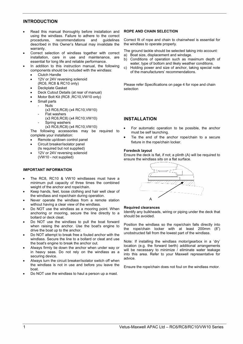
fixture in the rope/chain locker. Foredeck layout Ensure the deck is flat, if not; a plinth (A) will be required to ensure the windlass sits on a flat surface.
A Required clearances Identify any bulkheads, wiring or piping under the deck that should be avoided. Position the windlass so the rope/chain falls directly into the rope/chain locker with at least 200mm (8”) unobstructed fall from the lowest part of the windlass. Note: If installing the windlass motor/gearbox in a ‘dry’ location (e.g. the forward berth) additional arrangements will be necessary to minimize / eliminate water leakage into this area. Refer to your Maxwell representative for advice. Ensure the rope/chain does not foul on the windlass motor.
2
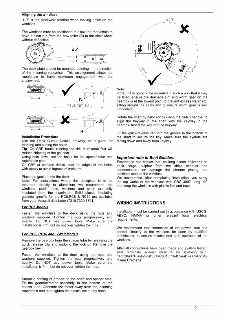
Aligning the windlass “UP” is the clockwise rotation when looking down on the windlass. The windlass must be positioned to allow the rope/chain to have a clear run from the bow roller (B) to the chainwheel without deflection.
The deck plate should be mounted pointing in the direction of the incoming rope/chain. This arrangement allows the rope/chain to have maximum engagement with the chainwheel.
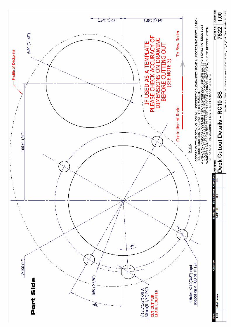
Installation Procedure Use the Deck Cutout Details drawing, as a guide for marking and cutting the holes. Tip: On GRP boats, running the drill in reverse first will reduce chipping of the gel coat. Using hole saws, cut the holes for the spacer tube and rope/chain pipe. On GRP or wooden decks, seal the edges of the holes with epoxy to avoid ingress of moisture. Place the gasket onto the deck. Note: For installations where the deckplate is to be mounted directly to aluminium we recommend the windlass, studs, nuts, washers and chain are fully insulated from the aluminium. Solid plastic insulating gaskets specific for the RC6,RC8 & RC10 are available from your Maxwell distributor (7319,7320,7321).
For RC6 Models
Fasten the windlass to the deck using the nuts and washers supplied. Tighten the nuts progressively and evenly. Do NOT use power tools. Make sure the installation is firm, but do not over tighten the nuts. For RC8, RC10 and VW10 Models
Remove the gearbox from the spacer tube by releasing the quick release clip and undoing the locknut. Remove the gearbox key.
Fasten the windlass to the deck using the nuts and washers supplied. Tighten the nuts progressively and evenly. Do NOT use power tools. Make sure the installation is firm, but do not over tighten the nuts.
Smear a coating of grease on the shaft and spacer tube. Fit the gearbox/motor assembly to the bottom of the spacer tube. Orientate the motor away from the incoming rope/chain and then tighten the plastic locknut by hand.
Note: If the unit is going to be mounted in such a way that it may be tilted, ensure the drainage slot and worm gear on the gearbox is at the lowest point to prevent excess water etc. sitting around the seals and to ensure worm gear is well lubricated. Rotate the shaft by hand (or by using the clutch handle) to align the keyway in the shaft with the keyway in the gearbox. Insert the key into the keyway. Fit the quick-release clip into the groove in the bottom of the shaft to secure the key. Make sure the eyelets are facing down and away from keyway.
Important note to Boat Builders Experience has shown that, on long ocean deliveries as deck cargo, sulphur from the ships exhaust and condensation can damage the chrome plating and stainless steel of the windlass. We recommend, after completing installation, you spray the top works of the windlass with CRC 3097 “long life” and wrap the windlass with plastic film and tape.
WIRING INSTRUCTIONS Installation must be carried out in accordance with USCG, ABYC, NMMA or other relevant local electrical requirements.
We recommend that connection of the power lines and control circuitry to the windlass be done by qualified technicians, to ensure reliable and safe operation of the windlass.
After all connections have been made and system tested, seal terminals against moisture by spraying with: CRC2043 “Plasti-Coat”, CRC3013 “Soft Seal” or CRC2049 “Clear Urethane”.
3 Vetus-Maxwell APAC Ltd – RC6/RC8/RC10/VW10 Series
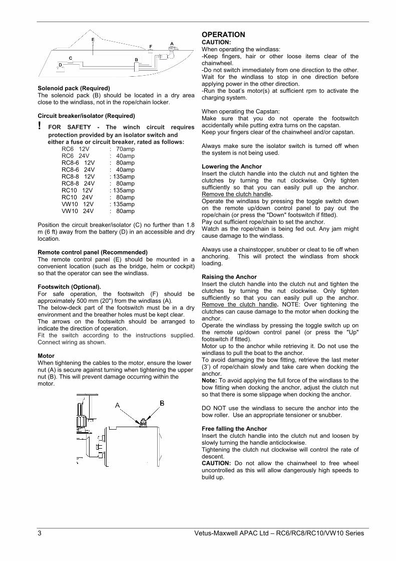
Solenoid pack (Required) The solenoid pack (B) should be located in a dry area close to the windlass, not in the rope/chain locker. Circuit breaker/isolator (Required)
! FOR SAFETY - The winch circuit requires protection provided by an isolator switch and either a fuse or circuit breaker, rated as follows: RC6 12V : 70amp RC6 24V : 40amp RC8-6 12V : 80amp RC8-6 24V : 40amp RC8-8 12V : 135amp RC8-8 24V : 80amp RC10 12V : 135amp RC10 24V : 80amp VW10 12V : 135amp VW10 24V : 80amp Position the circuit breaker/isolator (C) no further than 1.8 m (6 ft) away from the battery (D) in an accessible and dry location. Remote control panel (Recommended) The remote control panel (E) should be mounted in a convenient location (such as the bridge, helm or cockpit) so that the operator can see the windlass. Footswitch (Optional). For safe operation, the footswitch (F) should be approximately 500 mm (20") from the windlass (A). The below-deck part of the footswitch must be in a dry environment and the breather holes must be kept clear. The arrows on the footswitch should be arranged to indicate the direction of operation. Fit the switch according to the instructions supplied. Connect wiring as shown. Motor When tightening the cables to the motor, ensure the lower nut (A) is secure against turning when tightening the upper nut (B). This will prevent damage occurring within the motor.
OPERATION CAUTION: When operating the windlass: -Keep fingers, hair or other loose items clear of the chainwheel. -Do not switch immediately from one direction to the other. Wait for the windlass to stop in one direction before applying power in the other direction. -Run the boat’s motor(s) at sufficient rpm to activate the charging system. When operating the Capstan: Make sure that you do not operate the footswitch accidentally while putting extra turns on the capstan. Keep your fingers clear of the chainwheel and/or capstan. Always make sure the isolator switch is turned off when the system is not being used. Lowering the Anchor Insert the clutch handle into the clutch nut and tighten the clutches by turning the nut clockwise. Only tighten sufficiently so that you can easily pull up the anchor. Remove the clutch handle. Operate the windlass by pressing the toggle switch down on the remote up/down control panel to pay out the rope/chain (or press the "Down" footswitch if fitted). Pay out sufficient rope/chain to set the anchor. Watch as the rope/chain is being fed out. Any jam might cause damage to the windlass. Always use a chainstopper, snubber or cleat to tie off when anchoring. This will protect the windlass from shock loading.
Raising the Anchor Insert the clutch handle into the clutch nut and tighten the clutches by turning the nut clockwise. Only tighten sufficiently so that you can easily pull up the anchor. Remove the clutch handle. NOTE: Over tightening the clutches can cause damage to the motor when docking the anchor. Operate the windlass by pressing the toggle switch up on the remote up/down control panel (or press the "Up" footswitch if fitted). Motor up to the anchor while retrieving it. Do not use the windlass to pull the boat to the anchor. To avoid damaging the bow fitting, retrieve the last meter (3’) of rope/chain slowly and take care when docking the anchor. Note: To avoid applying the full force of the windlass to the bow fitting when docking the anchor, adjust the clutch nut so that there is some slippage when docking the anchor. DO NOT use the windlass to secure the anchor into the bow roller. Use an appropriate tensioner or snubber. Free falling the Anchor Insert the clutch handle into the clutch nut and loosen by slowly turning the handle anticlockwise. Tightening the clutch nut clockwise will control the rate of descent. CAUTION: Do not allow the chainwheel to free wheel uncontrolled as this will allow dangerously high speeds to build up.
4
Raising the Anchor Manually: RC8/RC10/VW10 models only Clamp the rope/chain so that it does not pay out when the clutch is released. Insert the clutch handle into the clutch nut and turn anticlockwise to loosen the clutch. Insert the clutch handle into the outer bi-square of the chainwheel and rotate clockwise to pull in the line. WARNING: There is no self-locking mechanism to prevent the windlass from turning freely during manual operation. The rope/chain must be clamped before the clutch handle is removed from the chainwheel and the clutch must be re-tightened. Using the Capstan Drum for Rope Warping: RC8,RC10 and VW10 Capstan models only The vertical capstan can be used independently from the chainwheel. This is ideal for handling mooring or docking lines, or retrieving a second anchor. For safety reasons, a footswitch is highly recommended. To haul in using the capstan: Make sure the anchor is secured. Insert the clutch handle into the clutch nut and turn anticlockwise until rotation stops. This will release the mechanism so that the chainwheel remains stationary while you operate the capstan. Wind up to three turns of rope onto the drum in a clockwise direction. Maintaining a light ‘tailing’ pull on the free end, start the capstan using the UP foot switch. As the capstan rotates, increase pull and ‘tail’ hand over hand to haul the rope. Reduce pull to slip the rope if required. To hold, stop the capstan while maintaining pull on the rope.
MAINTENENCE Every Trip
• Ensure clutch is adjusted correctly • Wash down topworks with fresh water • Check rope for wear and wash down with fresh
water Every 3 Months
• Remove chainwheel. Strip and grease clutch • Split gearbox from spacer tube, clean and re-
grease mating faces – RC8, RC10 & VW10 Models only
• Spray fresh water into drainage slot on gearbox, to breakdown and flush away any build up of salt/debris, which may have accumulated – RC8, RC10 & VW10 Models only.
• Check level of oil in gearbox using the sight glass. If necessary top up. – RC8, RC10 & VW10 Models only
• Clean the Windlass with a cloth damp with Kerosene (paraffin). Spray preferably with CRC3097 “Long Life” or alternatively, CRC6-66 or WD40. Polish off with a clean non-fluffy cloth.
• The under deck components should be sprayed, preferably with CRC 3097 “Long Life” or alternatively, CRC6-66 or WD40.
• Check tightness of all fasteners.
Every Year • The motor should be serviced by a qualified
technician. • Remove any rust build up from the casing and paint
with a suitable coating
Every 3 Years • The gearbox should be serviced by an authorised
service agent.
Specifications Electric Motor : Direct Current motor Voltage : 12V DC or 24V DC Rated Output : RC6: 500W
: RC8-6 : 600W : RC8-8: 1000W : RC10-8: 1000W : RC10-10: 1200W : VW10-8: 1000W : VW10-10: 1200W
Maximum Pull : RC6: 350kg (770 lbs)
: RC8-6: 350kg (770 lbs) : RC8-8: 600kg (1320 lbs) : RC10-8: 700kg (1540 lbs) : RC10-10: 850kg (1870 lbs) : VW10-8: 700kg (1540 lbs) : VW10-10: 850kg (1870 lbs)
Haulage speed : RC6: 21-24 m/min 69-79 ft/min (Dependant on : RC8-6: 24-29 m/min
the load) 79-92 ft/min : RC8-8: 28-32 m/min
92-105 ft/min : RC10-8: 20-24 m/min
65-79 ft/min : RC10-10: 20-24 m/min 65-79 ft/min : VW10-8: 20-24 m/min 65-79 ft/min : VW10-10: 20-24 m/min 65-79 ft/min Rope size : RC6: 12mm (1/2”) : RC8-6: 12mm (1/2”)
: RC8-8: 14-16mm (9/16”-5/8”) : RC10-8: 14-16mm (9/16”-5/8”)
: RC10-10: 16mm (5/8”) : VW10-8: 14-16mm (9/16”-5/8”)
: VW10-10: 16mm (5/8”) Chain size : RC6: 6mm-7mm (¼”) short ink : RC8-6: 6mm-7mm (¼”) short link
: RC8-8: 8mm (5/16”) short link : RC10-8: 8mm (5/16”) short link
: RC10-10: 10mm (3/8”) short link : VW10-8: 8mm (5/16”) short link
: VW10-10: 10mm (3/8”) short link Net weight : RC6: 8.5kgs (18.7lbs) : RC8-6: 12.5kgs (27.5lbs)
: RC8-8: 16.5kgs (36.3lbs) : RC10-8: 19kgs (42lbs)
: RC10-10: 20kgs (44lbs) : RC10-8: 21kgs (capstan) (46 lbs)
: RC10-10: 22kgs (capstan) (49 lbs) : VW10-8: 20kgs (capstan) (43 lbs)
: VW10-10: 21kgs (capstan) (46 lbs)

5 Vetus-Maxwell APAC Ltd – RC6/RC8/RC10/VW10 Series
Recommended lubricants: Gearbox oil RC8, RC10 & VW10 only: Capacity: 70 ml (2.4 fl oz) Type: SAE viscosity grade 90-110 (e.g., Shell Omala 320, Castrol Alpha SP320 or other approved equivalents). Main shaft, bearing, and clutch surfaces: Marine grease, Lithium or Lithium complex based (e.g. Duckhams Keenol or Castrol LMX).Do not use soap based greases. WARNING: When re-assembling care must be taken to ensure the key/keys are properly seated in the shaft. DO NOT wrap the motor with grease cloth as this prevents the cooling of the motor. Ordering Spare Parts Always consult manual supplied with product as details may have been revised. When ordering spare parts, please quote the following details. Windlass Model_________________ Serial number __________________ Power supply___________________ Note: For your nearest retailer, service agent or representative please refer to our website
www.maxwellmarine.com
! NOTE: Cable length is the total length from battery to winch then back to battery. Note: Cable size recommendations are based on a maximum 10% voltage drop when operating the windlass under load, smaller cables may be used however a drop in performance can be expected.
Cable Lengths
RC6 12V Systems
Cable Length Cable Size
mm² AWG Up to 10m (35') 14 6 10m - 20m (35' - 62') 22 4
RC6 24V Systems
Cable Length Cable Size
mm² AWG Up to 10m (35') 8.8 8 10m - 20m (35' - 65') 10.5 7
RC8-6 12V Systems
Cable Length Cable Size
mm² AWG
Up to 10m (15' - 35') 14 6 10m - 15m (35' - 50') 22 4 15m - 20m (50' - 65') 34 2
RC8-6 24V Systems
Cable Length Cable Size
mm² AWG Up to 10m (35') 8.8 8 10m - 20m (35' - 65') 14 6
RC8-8 12V Systems
Cable Length Cable Size
mm² AWG Up to 10m (35') 22 4 10m - 20m (35' - 65') 34 2 20m - 28m (65' - 91') 54 0
RC8-8 24V Systems
Cable Length Cable Size
mm² AWG Up to 18m (40') 6.5 9 18m - 28m (40' - 91') 10.5 7
RC10/ VW10 12V Systems
Cable Length Cable Size
mm² AWG Up to 10m (35') 22 4 10m - 15m (35' - 50') 34 2 15m - 20m (50' - 65') 42 1 20m - 25m (65' - 82') 54 0 25m - 32m (82' - 105') 68 00
RC10/ VW10 24V Systems
Cable Length Cable Size
mm² AWG Up to 15m (50') 10.5 7 15m - 25m (50' - 82') 16 5 25m - 32m (82' - 105') 22 4
6
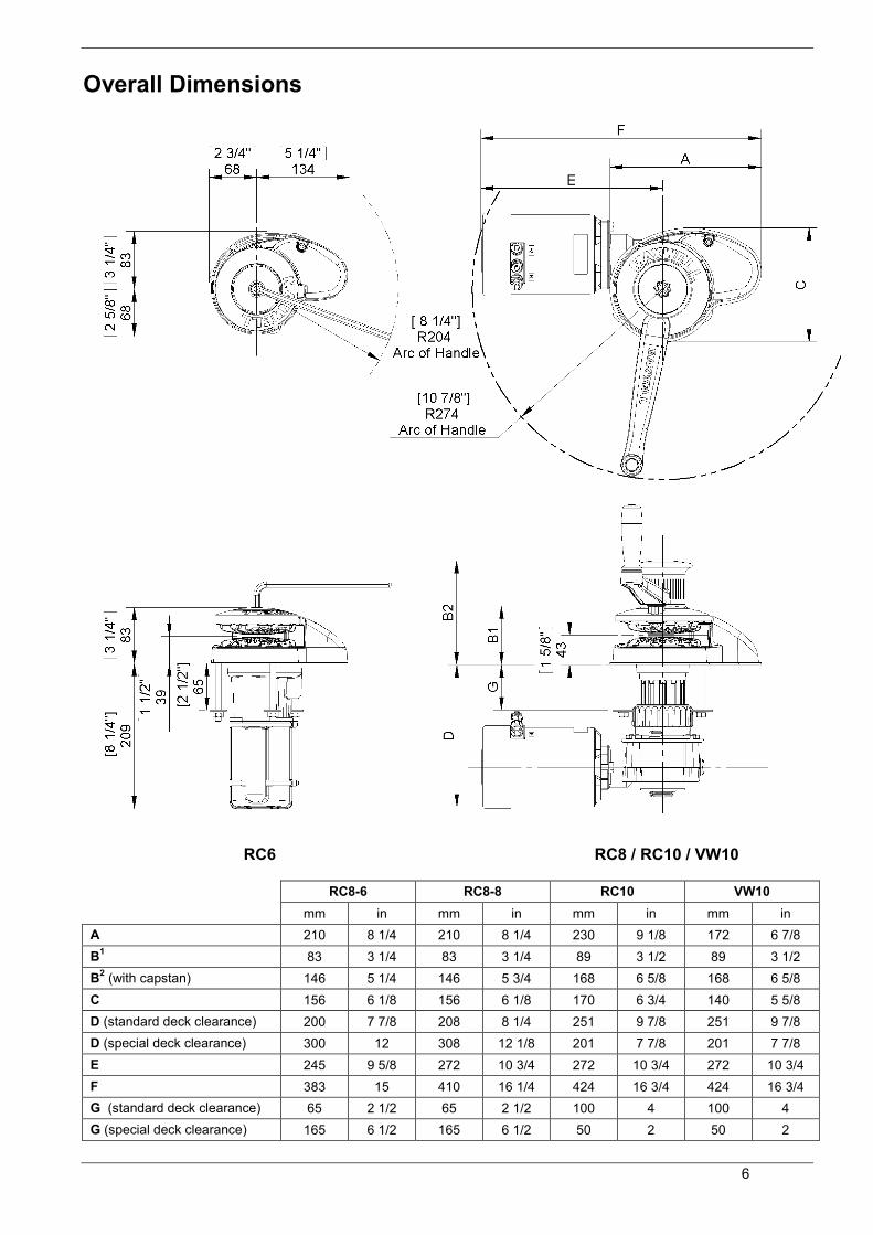
Overall Dimensions
RC6 RC8 / RC10 / VW10 RC8-6 RC8-8 RC10 VW10 mm in mm in mm in mm in A 210 8 1/4 210 8 1/4 230 9 1/8 172 6 7/8 B1 83 3 1/4 83 3 1/4 89 3 1/2 89 3 1/2 B2 (with capstan) 146 5 1/4 146 5 3/4 168 6 5/8 168 6 5/8 C 156 6 1/8 156 6 1/8 170 6 3/4 140 5 5/8 D (standard deck clearance) 200 7 7/8 208 8 1/4 251 9 7/8 251 9 7/8 D (special deck clearance) 300 12 308 12 1/8 201 7 7/8 201 7 7/8 E 245 9 5/8 272 10 3/4 272 10 3/4 272 10 3/4 F 383 15 410 16 1/4 424 16 3/4 424 16 3/4 G (standard deck clearance) 65 2 1/2 65 2 1/2 100 4 100 4 G (special deck clearance) 165 6 1/2 165 6 1/2 50 2 50 2

7 Vetus-Maxwell APAC Ltd – RC6/RC8/RC10/VW10 Series
Wiring Schematic
Typical wiring to suit: RC6, RC8-6
Typical wiring to suit: RC8-8, RC10-8, RC10-10, VW10-8, VW10-10
8
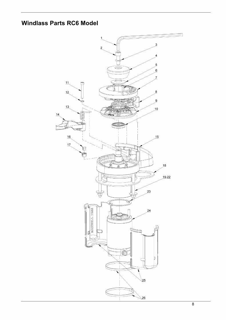
Windlass Parts RC6 Model
9 Vetus-Maxwell APAC Ltd – RC6/RC8/RC10/VW10 Series
Windlass Parts RC6 Model
Item no. Component description Qty Part to order Includes 1 Handle 1 SP3505 2 Capscrew – M10 x 30 1 SP0169 3 Spring washer – M10 1 SP0466 4 Clutch cone 1 7061C 5 Bellville washer 1 SP0484 6 Cap Screws 2 SP4508 7 Chainwheel - upper - 6mm-1/4" 1 P103314 6(x2),7,8,9 8 Stripper 1 7010 9 Chainwheel - lower - 6mm-1/4" 1 P103314 6(x2),7,8,9 10 Oil Seal 1 SP2795 11 Capscrew – M6 x 45 1 SP4501 12 Spring washer – M6 1 SP0474 13 Pressure Arm spring 1 7037 14 Pressure Arm 1 7009 15 Deckplate 1 P102569 New windlass 16 Plug 1 SP3519 17 Bush 1 SP3518 18 Gasket – Deck 1 7066 19 Stud 3 4281 20 Flat washer 3 P101667 20,21,22 21 Spring washer 3 P101667 20,21,22 22 Nut M8 3 P101667 20,21,22 23 Gasket – Motor 1 7063 24 Motor – 12V 1 SP4189 25 Motor cover 2 7055 26 Cable tie 2 SP3527
Not Shown Replacement Brush kit for motor 1 SP2932 Not Shown Motor Gaskets 2 SP2931
10
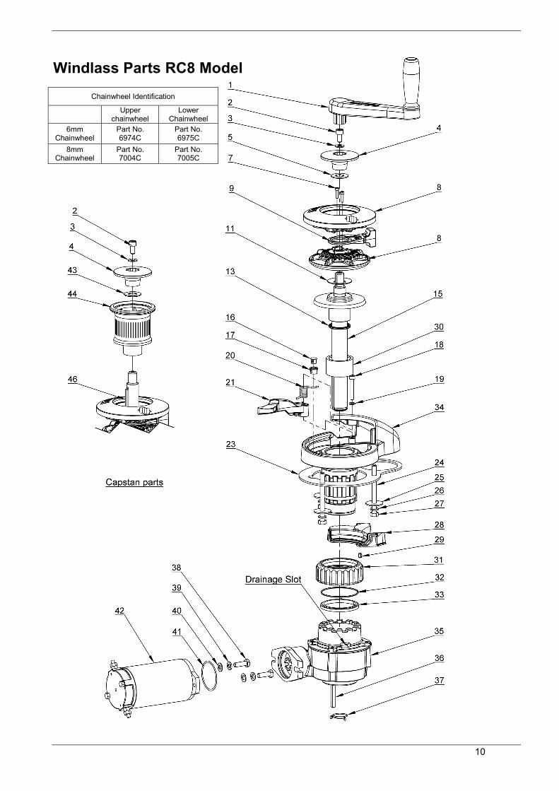
Windlass Parts RC8 Model
Chainwheel Identification
Upper chainwheel
Lower Chainwheel
6mm Chainwheel
Part No. 6974C
Part No. 6975C
8mm Chainwheel
Part No. 7004C
Part No. 7005C
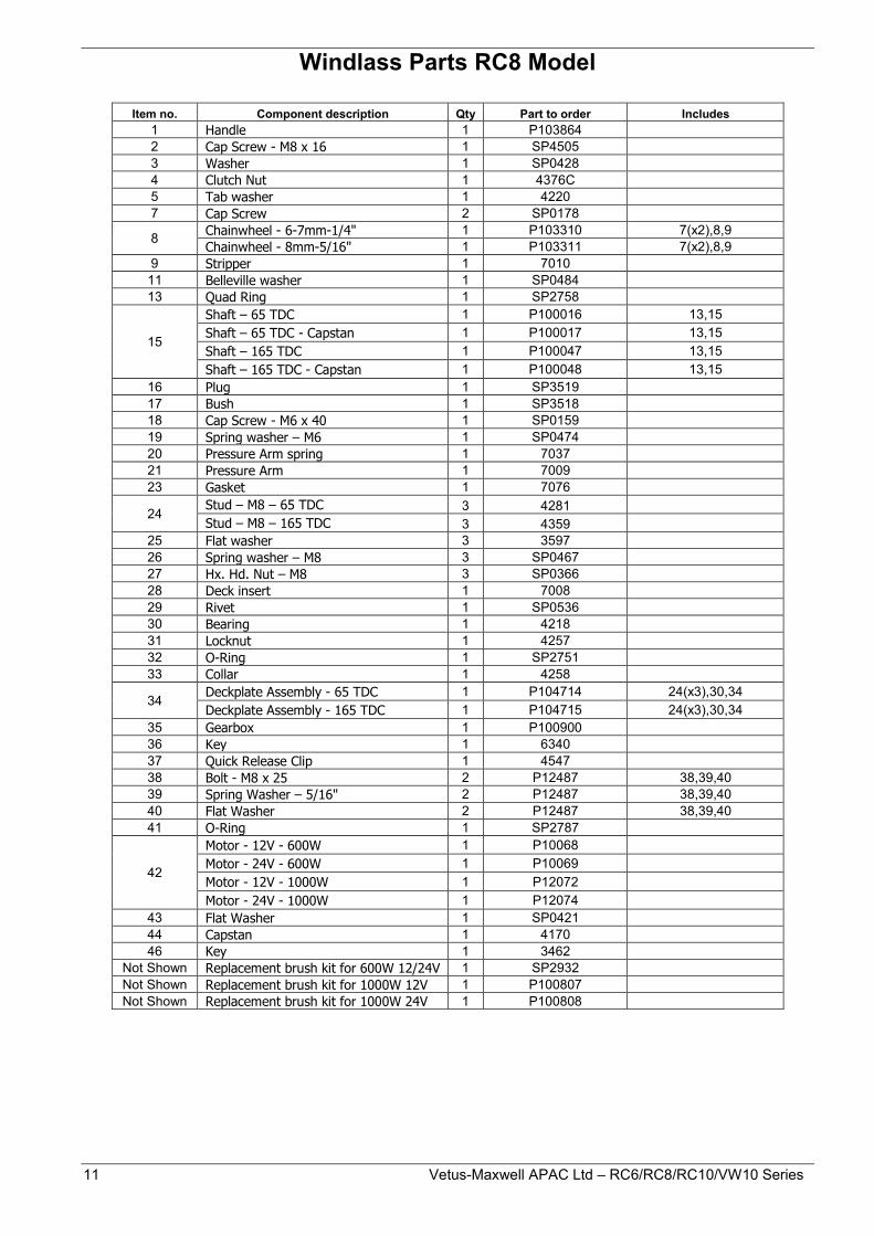
11 Vetus-Maxwell APAC Ltd – RC6/RC8/RC10/VW10 Series
Windlass Parts RC8 Model
Item no. Component description Qty Part to order Includes 1 Handle 1 P103864 2 Cap Screw - M8 x 16 1 SP4505 3 Washer 1 SP0428 4 Clutch Nut 1 4376C 5 Tab washer 1 4220 7 Cap Screw 2 SP0178
8 Chainwheel - 6-7mm-1/4" 1 P103310 7(x2),8,9 Chainwheel - 8mm-5/16" 1 P103311 7(x2),8,9
9 Stripper 1 7010 11 Belleville washer 1 SP0484 13 Quad Ring 1 SP2758
15
Shaft – 65 TDC 1 P100016 13,15 Shaft – 65 TDC - Capstan 1 P100017 13,15 Shaft – 165 TDC 1 P100047 13,15 Shaft – 165 TDC - Capstan 1 P100048 13,15
16 Plug 1 SP3519 17 Bush 1 SP3518 18 Cap Screw - M6 x 40 1 SP0159 19 Spring washer – M6 1 SP0474 20 Pressure Arm spring 1 7037 21 Pressure Arm 1 7009 23 Gasket 1 7076
24 Stud – M8 – 65 TDC 3 4281 Stud – M8 – 165 TDC 3 4359
25 Flat washer 3 3597 26 Spring washer – M8 3 SP0467 27 Hx. Hd. Nut – M8 3 SP0366 28 Deck insert 1 7008 29 Rivet 1 SP0536 30 Bearing 1 4218 31 Locknut 1 4257 32 O-Ring 1 SP2751 33 Collar 1 4258
34 Deckplate Assembly - 65 TDC 1 P104714 24(x3),30,34 Deckplate Assembly - 165 TDC 1 P104715 24(x3),30,34
35 Gearbox 1 P100900 36 Key 1 6340 37 Quick Release Clip 1 4547 38 Bolt - M8 x 25 2 P12487 38,39,40 39 Spring Washer – 5/16" 2 P12487 38,39,40 40 Flat Washer 2 P12487 38,39,40 41 O-Ring 1 SP2787
42
Motor - 12V - 600W 1 P10068 Motor - 24V - 600W 1 P10069 Motor - 12V - 1000W 1 P12072 Motor - 24V - 1000W 1 P12074
43 Flat Washer 1 SP0421 44 Capstan 1 4170 46 Key 1 3462
Not Shown Replacement brush kit for 600W 12/24V 1 SP2932 Not Shown Replacement brush kit for 1000W 12V 1 P100807 Not Shown Replacement brush kit for 1000W 24V 1 P100808
12
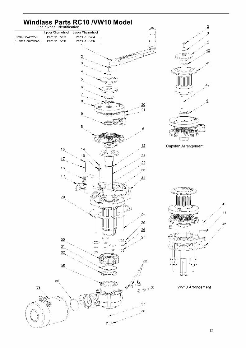
Windlass Parts RC10 /VW10 Model

13 Vetus-Maxwell APAC Ltd – RC6/RC8/RC10/VW10 Series
Windlass Parts RC10 /VW10 Model
Item no. Component description Qty Part to order Includes 1 Handle 1 P103864 2 Cap Screw - M8 x 16 1 SP4505 3 Washer 1 SP0428 4 Clutch Nut 1 6914 5 Clutch Cone - Upper 1 6090 6 Belleville Washer 2 SP0488 7 Cap Screw 3 SP4503
8 Chainwheel - 8mm-5/16" 1 P103308 7(x3),8,9 Chainwheel - 10mm-3/8" 1 P103309 7(x3),8,9
9 Stripper 1 6915 12 Quad Ring 1 SP2758 14 Plug 1 SP3519 15 Bush 1 SP3518 16 Cap Screw - M6 x 45 1 SP4501 17 Spring Washer 1 SP0474 18 Spring 1 7037 19 Pressure Arm 1 7009 20 Cap Screw - M6 x 60 1 SP4502 21 Spring Washer 1 SP0474 22 Pin 1 SP0545
24 Stud - 50TDC 4 4281 Stud - 100TDC 4 5256
25 Washer 4 3597 26 Spring Washer – M8 4 SP0467 27 Nut – M8 4 SP0366
28 Shaft Assembly- 50TDC - Capstan 1 P102527 12,28 Shaft Assembly - 100TDC 1 P104700 12,28 Shaft Assembly - 100TDC - Capstan 1 P104701 12,28
29 Deckplate Gasket 1 7040 30 Locknut 1 4257 31 O-Ring 1 SP2751 32 Collar 1 4258 33 Bearing 1 4218
34 Deckplate Assembly – 50 TDC 1 P104721 24,33,34 Deckplate Assembly - 100TDC 1 P104722 24,33,34
35 Gearbox - 56:1 1 P102730 36 Motor bolt kit 1 P12487 37 Key 1 6340 38 Quick Release Clip 1 4547
39
Motor - 12V - 1000W 1 P12072 Motor - 24V - 1000W 1 P12074 Motor - 12V - 1200W 1 P12073
Motor - 24V - 1200W 1 P12074 40 Flat Washer 1 SP0421 41 Capstan 1 7074 42 Key - Capstan 1 6340 43 Tension pin 1 SP0551 44 Deckplate 10 VW 1 7416 45 Gasket 10 VW 1 7624
Not Shown Replacement brush kit for motor 12V 1 P100807 Not Shown Replacement brush kit for motor 24V 1 P100808

14
{This page intentionally left blank}

15 Vetus-Maxwell APAC Ltd – RC6/RC8/RC10/VW10 Series

16
17 Vetus-Maxwell APAC Ltd – RC6/RC8/RC10/VW10 Series

18
19 Vetus-Maxwell APAC Ltd – RC6/RC8/RC10/VW10 Series
LIMITED WARRANTY Warranty: Vetus-Maxwell APAC Ltd provides a three year limited warranty on windlasses for pleasure boat usage, and a one year limited warranty for those systems used on commercial or charter vessels. Warranty, service and parts are available around the world. Contact your nearest Maxwell office for a complete list of service centres and distributors. This warranty is subject to the following conditions and limitations: 1. This Warranty will be null and void if (a) there is any neglect or failure to properly maintain and service the products.
(b) the products are serviced, repaired or maintained improperly or by unauthorised persons.
(c) loss or damage is attributed to any act, matter or omission beyond the reasonable control of Vetus-Maxwell APAC Ltd or the purchaser.
2. Vetus-Maxwell APAC Ltd liability shall be limited to repair or replacement (as determined by Vetus-Maxwell APAC Ltd) of the goods or parts defective in materials or workmanship.
3. Determination of the suitability of the product and the materials for the use contemplated by the buyer is the sole responsibility of the buyer, and Vetus-Maxwell APAC Ltd shall have no responsibility in connection with such suitability.
4. Vetus-Maxwell APAC Ltd shall not be liable for any loss, damages, harm or claim attributed to: (a) use of the products in applications for which the products are not intended. (b) corrosion, wear and tear or improper installation. (c) improper use of the product.
5. This Warranty applies to the original purchaser of the products only. The benefits of the Warranty are not transferable to subsequent purchasers.
6. Vetus-Maxwell APAC Ltd shall not be responsible for shipping charges or installation labour associated with any warranty claims. 7. There are no warranties of merchantability, fitness for purpose, or any other kind, express or implied, and none shall be implied by
law. If any such warranties are nonetheless implied by law for the benefit of the customer they shall be limited to a period of three years from the original purchase by the user.
8. Vetus-Maxwell APAC Ltd shall not be liable for consequential damages to any vessel, equipment, or other property or persons due to use or installation of Maxwell equipment.
9. This Warranty sets out your specific legal rights allowed by Vetus-Maxwell APAC Ltd ; these may be varied by the laws of different countries. In addition, the purchaser may also have other legal rights which vary from country to country.
10. To make a claim under this Warranty, contact your nearest Maxwell Marine office or distributor. Proof of purchase and authorisation from Vetus-Maxwell APAC Ltd will be required prior to any repairs being attempted.
Purchaser
To be eligible for warranty protection, please either complete the form below at the time of purchase and return it to the appropriate retailer or supplier of the goods, or fill out the electronic warranty form on our website, www.maxwellmarine.com
Name:
Address:
Telephone: Facsimile
Supplier / Dealer
Name:
Address:
Telephone: Facsimile
Windlass Model Serial Number
Date of Purchase
Boat Type
Windlasses Supplied
With boat
Fitted by boat yard/dealer
Purchased from dealer/chandler
Name L.O.A.
Built by