
R.Bailey, March 2008 Beam plans for Accelerator Systems R.Bailey, F.Zimmermann eLTC Summary March...
27
R.Bailey, March 2008 R.Bailey, March 2008 Beam plans for Accelerator Systems Beam plans for Accelerator Systems R.Bailey, F.Zimmermann R.Bailey, F.Zimmermann eLTC Summary eLTC Summary March 2008 March 2008
-
Upload
bertha-fisher -
Category
Documents
-
view
218 -
download
0
Transcript of R.Bailey, March 2008 Beam plans for Accelerator Systems R.Bailey, F.Zimmermann eLTC Summary March...
R.Bailey, March 2008R.Bailey, March 2008
Beam plans for Accelerator SystemsBeam plans for Accelerator Systems
R.Bailey, F.ZimmermannR.Bailey, F.Zimmermann
eLTC SummaryeLTC Summary
March 2008March 2008

R.Bailey, March 2008R.Bailey, March 2008
Overall commissioning strategy for protons (estOverall commissioning strategy for protons (estdd. 2005). 2005)
Hardware commissioning
Machine checkout
Beam commissioning
43 bunch operation
75ns ops
25ns ops IInstall Phase II and MKB
25ns ops II
Stage A B C
No beam Beam
D
A.A. Pilot physics runPilot physics run First collisionsFirst collisions 43 bunches, no crossing angle, no squeeze, moderate intensities43 bunches, no crossing angle, no squeeze, moderate intensities Push performancePush performance Performance limit 10Performance limit 103232 cm cm-2-2 s s-1-1 (event pileup) (event pileup)
B.B. 75ns operation75ns operation Establish multi-bunch operation, moderate intensitiesEstablish multi-bunch operation, moderate intensities Relaxed machine parameters (squeeze and crossing angle)Relaxed machine parameters (squeeze and crossing angle) Push squeeze and crossing angle Push squeeze and crossing angle Performance limit 10Performance limit 103333 cm cm-2-2 s s-1-1 (event pileup) (event pileup)
C.C. 25ns operation I25ns operation I Nominal crossing angleNominal crossing angle Push squeezePush squeeze Increase intensity to 50% nominalIncrease intensity to 50% nominal Performance limit 2 10Performance limit 2 103333 cm cm-2-2 s s-1-1
D.D. 25ns operation II25ns operation II Push towards nominal performancePush towards nominal performance
*
bk
N
Optimise
Pileup
Losses
Beampower
Complexity
Minimise
)( *

R.Bailey, March 2008R.Bailey, March 2008
Stage A: Commissioning procedures (LHCCWG)Stage A: Commissioning procedures (LHCCWG)
Web based with EDMS approval http://lhccwg.web.cern.ch/lhccwg/overview_index.htm

R.Bailey, March 2008R.Bailey, March 2008
Stage A: Commissioning PhasesStage A: Commissioning Phases
Phase
A.1 First turn Injection commissioning and threading
A.2 Circulating pilot Establish circulating beam, closed orbit, tunes, RF capture
A.3 450 GeV initial commissioning System commissioning (instrumentation, beam dump)
A.4 450 GeV optics Beta beating, dispersion, coupling, non-linear field quality, aperture
A.5 450 GeV, increasing intensity Prepare the LHC for unsafe beam
A.6 450 GeV, two beam operation Handle 2 beams together
A.7 450 GeV, collisions If requested by experiments
A.8 Snap-back and ramp Single beam, 2 beams
A.9 Top energy checks Single beam, 2 beams
A.10 Top energy Collisions
A.11 Squeeze Commissioning the Betatron squeeze in all IP’s
A.12 Experimental magnets Beam commissioning with experimental magnets

R.Bailey, March 2008R.Bailey, March 2008
Stage A: Phase 3 – Initial system commissioningStage A: Phase 3 – Initial system commissioning
Phase
A.1
A.2
A.3
A.4
A.5
A.6
A.7
A.8
A.9
A.10
A.11
A.12
Phase Step Activity Who (OP +)
A.3
A3.1 Final RF commissioning with Pilot Intensity RF
A3.2 BCTFR and BPM checks with Pilot Intensity BI
A3.3 First Commissioning of Beam Dumping System (pilot) BT BI ATB
A3.4 Commission systems with higher intensity (3 x 10¹⁰) BT BI RF
A3.5 Establish cycling machine (3 x 10¹⁰) OP
A3.6 Lifetime optimisation (3 x 10¹⁰) OP
A3.7 Further commissioning of beam instrumentation (3 x 10¹⁰) BI
A3.8 Basic optics checks in addition to LOCO Results (3 x 10¹⁰) AP BI RF
A3.9 Further commissioning of beam dumping system (3 x 10¹⁰) BT BI ATB
A3.10 Commission feedback systems (3 x 10¹⁰) RF BI
A3.11 Rough Setting up of the TDI (3 x 10¹⁰) BT ATB
Phase Will be working with Max beam Who (OP +)
A.3
RF systemsBeam dump with pilotTDIBCTTune meter and PLLWire scannersSynchrotron lightRest Gas Ionisation monitorMulti turn acquisitionFeedback systems
3 1010
RFATBBIBT

R.Bailey, March 2008R.Bailey, March 2008
Stage A: The view from the expertsStage A: The view from the experts
Phase
A.1
A.2
A.3
A.4
A.5
A.6
A.7
A.8
A.9
A.10
A.11
A.12 BT RF Etc BIEtc
Etc Etc

R.Bailey, March 2008R.Bailey, March 2008
Session 4 – Beam plans for accelerator systemsSession 4 – Beam plans for accelerator systems
Taking the Beam Commissioning Procedures as a basis, each Taking the Beam Commissioning Procedures as a basis, each presentation should elaborate the details of how the presentation should elaborate the details of how the accelerator system in question is commissioned with beam accelerator system in question is commissioned with beam through the various phases of the established plan. through the various phases of the established plan.
Each presentation should cover Each presentation should cover what needs to be done at the various stages of commissioningwhat needs to be done at the various stages of commissioning how it will be donehow it will be done who will do itwho will do it how long it is expected to takehow long it is expected to take
As a minimum, each presentation should cover commissioning As a minimum, each presentation should cover commissioning up to the performance levels attainable in phase A. A look up to the performance levels attainable in phase A. A look forward into later stages is left to the discretion of the speakerforward into later stages is left to the discretion of the speaker

R.Bailey, March 2008R.Bailey, March 2008
Session 4 – Beam plans for accelerator systemsSession 4 – Beam plans for accelerator systems
Accelerator system Speaker Time
Beam Commissioning Procedures R.Bailey 20+10
Injection and associated protection devices V.Kain 30+10
Power converters (tracking between sectors) F.Bordry 20+10
coffee
RF acceleration systems P.Baudrenghien 30+10
Beam dump and associated protection devices B.Goddard 20+10
2h+1h
lunch
BI systems R.Jones 30+10
RADMON T.Wijnands 20+10
Transverse damper W.Hofle 20+10
coffee
Collimators R.Assmann 30+10
Machine protection J.Uythoven 20+10
2h+1h

R.Bailey, March 2008R.Bailey, March 2008
Power converters’ biblePower converters’ bible

R.Bailey, March 2008R.Bailey, March 2008
Power convertersPower converters
Tracking between the 8 main dipole convertersTracking between the 8 main dipole converters 20ppm accuracy after calibration gives 0.7mm20ppm accuracy after calibration gives 0.7mm OKOK
Tracking between the dipole and quadrupole convertersTracking between the dipole and quadrupole converters 20ppm accuracy gives tune change 0.0320ppm accuracy gives tune change 0.03 OKOK
Tracking between the quadrupole convertersTracking between the quadrupole converters 20ppm accuracy gives very small 20ppm accuracy gives very small beating beating OKOK
Above reachable after calibration (automatic procedure)Above reachable after calibration (automatic procedure)
Sector 45 tests show very good performance (no triplet)Sector 45 tests show very good performance (no triplet)
LHC Power Converters performance will be measured and improved mainly without dedicated beam time
Periodic calibration will be required
PC experts should be very close to beam operation, for issues like Offsets between sectors Tracking measurement and correction Ramp

R.Bailey, March 2008R.Bailey, March 2008
Injection and associated protection devicesInjection and associated protection devices
TDIMKI +90˚
TCDD
TCLIBTCLIA
KickerMKI
LEFT OF IP2 (H plane)
RIGHT OF IP2 (H plane)
TCLIM
SeptumMSI
TCDI

R.Bailey, March 2008R.Bailey, March 2008
Injection and associated protection devicesInjection and associated protection devices
Phase A1 (First turn)Phase A1 (First turn) First to TDIFirst to TDI Then beyond and into threadingThen beyond and into threading
Phase A2 and A3 (Circulating pilot++)Phase A2 and A3 (Circulating pilot++) Injection oscillationsInjection oscillations Re-steer injectionRe-steer injection
Phase A4 (450GeV optics)Phase A4 (450GeV optics) Stability (1000 shots inject and dump)Stability (1000 shots inject and dump) Aperture in injection regionAperture in injection region MKI waveformMKI waveform Injection matchingInjection matching
Phase A5 (Increase intensity)Phase A5 (Increase intensity) Multi bunch injection and Protection devicesMulti bunch injection and Protection devices
1-2 shifts/beam
1-2 shifts/beam
1-2 shifts/beam
1-2 shifts/beam
1313
R1
Low-levelLoops
Processor
Radial PUFront-end
VCXO
Phase Discri
F RF Prog 1
Radial loop
Phase loop
Synchro loop
DDS1 DDS2
Sync
F1,P
1
F2,P
2
F1 F2
1/h divider
Master F rev
To Ring 1 Cavity Controllers (fibers)
Dual Frequency Program and
Rephasor FPGA
Function Gen. Function Gen.
F RF Prog 2
DUAL FREQUENCY
PRGM
Master F RF
Beam 1Rad. PU
Beam/Vt phase
RF/Fprog phase
F out
Rad
Pos
.
Fiber Optic TX
BEAM CONTROL
LOOPS MODULE
Radial steering with radial loop
Coarse F1
LF switch
Phase Discri
7 TeV synthesizer
Phase shifter
180 deg hybrid
a b
BEAM POS
MODULE
FPGAA
DC
SYNCHROMODULE
Ib RF Summing Network
Vt
Phase PU
AD
C
CORDIC (+ AGC?)
Bunch/RF phase
CORDIC (+ AGC?)
Vt/RF phase
Phase Difference
and Averaging
BEAM PHASE
MODULE
AD
C
Cavities
Analog I/Q demod
Analog I/Q demod
Master FrfMaster Frf
AD
C
AD
C
Delay adjust
Function Gen.
fsync
fphase
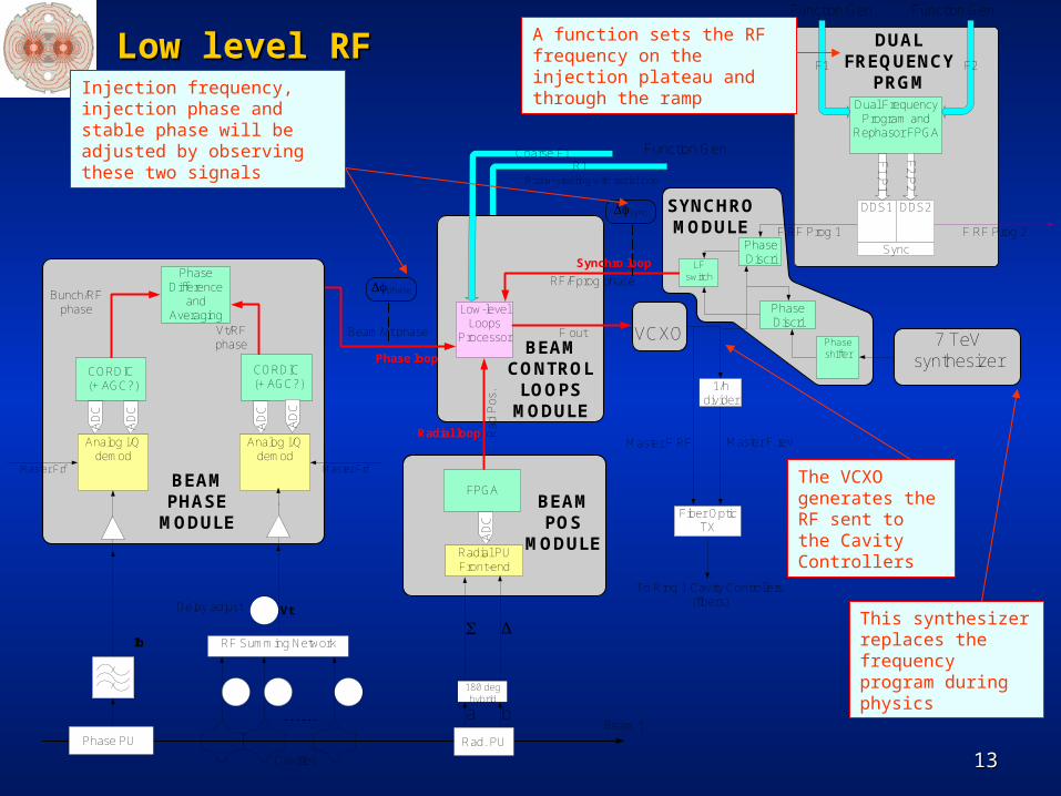
A function sets the RF frequency on the injection plateau and through the ramp
Injection frequency, injection phase and stable phase will be adjusted by observing these two signals
The VCXO generates the RF sent to the Cavity Controllers
This synthesizer replaces the frequency program during physics
Low level RFLow level RF

R.Bailey, March 2008R.Bailey, March 2008
RF acceleration systemsRF acceleration systems
Phase A1 (First turn)Phase A1 (First turn) RF OFFRF OFF
Label buckets (Numerology and cogging)Label buckets (Numerology and cogging) Signal tuningSignal tuning
Phase A2 (Circulating pilot++)Phase A2 (Circulating pilot++) RF ONRF ON
Adjust RF frequencyAdjust RF frequency Commission phase loop and synchro loopCommission phase loop and synchro loop Capture and check phasing of cavities with beamCapture and check phasing of cavities with beam Adjust positions of bunches for collisions in IRsAdjust positions of bunches for collisions in IRs
Phases A3 onwardsPhases A3 onwards As and when needed by commissioning programAs and when needed by commissioning program
Commission radial loop for the rampCommission radial loop for the ramp Commission multi bunch injectionsCommission multi bunch injections Commission multi batch injectionsCommission multi batch injections RampingRamping Rephasing on the flat topRephasing on the flat top
1 shift
8 shifts
8 shifts

R.Bailey, March 2008R.Bailey, March 2008
Beam dump and associated protection devicesBeam dump and associated protection devices

R.Bailey, March 2008R.Bailey, March 2008
Beam dump and associated protection devicesBeam dump and associated protection devices
Phase A3 (Circulating pilot++)Phase A3 (Circulating pilot++) First controlled extractionsFirst controlled extractions
Phase A4 (450GeV optics)Phase A4 (450GeV optics) IR6 aperture and IR6 aperture and TCDQTCDQ
Phase A5 (Increase intensity)Phase A5 (Increase intensity) Abort gap cleaningAbort gap cleaning Extraction trajectoriesExtraction trajectories
Phase A8 (Ramp)Phase A8 (Ramp) Energy trackingEnergy tracking
Phase A9 (Top energy)Phase A9 (Top energy) IR6 aperture and IR6 aperture and TCDQTCDQ Abort gap cleaningAbort gap cleaning
Phase A11 (Squeeze)Phase A11 (Squeeze) Different opticsDifferent optics TCDQTCDQ
3-4 shifts
1-2 shifts
6-10 shifts
1-3 shifts
4-6 shifts
1 shift

R.Bailey, March 2008R.Bailey, March 2008
Beam InstrumentationBeam Instrumentation
Phase A1 (First turn)Phase A1 (First turn) Screens, BPM in asynchronous mode, fast BCT, BLMScreens, BPM in asynchronous mode, fast BCT, BLM Check polarity errors while threading (stage the repairs)Check polarity errors while threading (stage the repairs)
Phase A3 (Circulating pilot++)Phase A3 (Circulating pilot++) BPM in synchronous mode and systematic calibration (BPM, COD)BPM in synchronous mode and systematic calibration (BPM, COD) DC BCT & lifetimeDC BCT & lifetime Tune meter with beam excitation Tune meter with beam excitation
Via transverse damper easiestVia transverse damper easiest Via MKQVia MKQ
Head tail monitor for ChromaticityHead tail monitor for Chromaticity Wire scanner, SL (needs undulator), BGI (needs gas injection)Wire scanner, SL (needs undulator), BGI (needs gas injection) Abort gap monitor (needs undulator)Abort gap monitor (needs undulator)
Phase A8 (Ramp)Phase A8 (Ramp) Continuous orbit, tune, coupling and chromaticity (+ feedbacks)Continuous orbit, tune, coupling and chromaticity (+ feedbacks) Continuous emittance monitoring (SL from D3 above 2TeV)Continuous emittance monitoring (SL from D3 above 2TeV)
Phase A10 (Collisions)Phase A10 (Collisions) Luminosity (BRANA (ionisation) in 1&5, BRANB (CdTe in 2&8)Luminosity (BRANA (ionisation) in 1&5, BRANB (CdTe in 2&8) SchottkySchottky

R.Bailey, March 2008R.Bailey, March 2008
Beam Instrumentation issuesBeam Instrumentation issues
Chicken and Egg situationChicken and Egg situation Good measurements needed to get good beamGood measurements needed to get good beam Good beam needed to get good measurementsGood beam needed to get good measurements
BTV images in LSS3 and LSS4BTV images in LSS3 and LSS4 Single shot OK but not turn by turnSingle shot OK but not turn by turn Need fast camerasNeed fast cameras Not for 2008 (resource issues)Not for 2008 (resource issues)
BPM in Intensity modeBPM in Intensity mode Requires intensity for precision better than 50%Requires intensity for precision better than 50% Complicated software mapping (B1 position Complicated software mapping (B1 position ↔↔ B2 intensity) B2 intensity) Have auto trigger anywayHave auto trigger anyway
Fast BCT on single bunchFast BCT on single bunch BGIBGI
Needs gas injection for low intensitiesNeeds gas injection for low intensities Considered risky by AT/VACConsidered risky by AT/VAC
BRANBRAN Ionisation monitors arrive just in time at best Ionisation monitors arrive just in time at best
Hence iterative. Heavily interleaved with the commissioning program
Time estimates difficult

R.Bailey, March 2008R.Bailey, March 2008
Radiation monitoring systemsRadiation monitoring systems
Several systems, various groups, different objectivesSeveral systems, various groups, different objectives RAMSESRAMSES BLMBLM RADMONRADMON BCM/BSCBCM/BSC
Collaborative approach proposed to observations at key stagesCollaborative approach proposed to observations at key stages Increase in beam intensityIncrease in beam intensity Increase in energyIncrease in energy Change of opticsChange of optics CollisionsCollisions
Distinguish betweenDistinguish between Simulations, shielding and monitoringSimulations, shielding and monitoring Radiation damage effectsRadiation damage effects
Need to define a system commissioning team for these systems
No dedicated beam time requested. In the shadow of other activities
R.Bailey, March 2008R.Bailey, March 2008
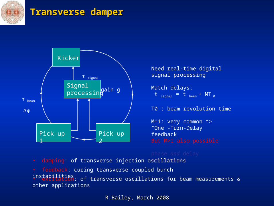
Transverse damperTransverse damper
Pick-up 1
Kicker
Signal processing
beam
signal
Pick-up 2
gain g
Need real-time digitalsignal processing
Match delays: t signal = t beam + MT 0
T0 : beam revolution time
M=1: very common -> “One -Turn-Delay” feedbackBut M>1 also possible
phase and delay adjustments
• feedback: curing transverse coupled bunch instabilities
• excitation: of transverse oscillations for beam measurements & other applications
• damping: of transverse injection oscillations

R.Bailey, March 2008R.Bailey, March 2008
Transverse damperTransverse damper
Damper essential to avoid increase of transverse emittance already in phase A (1-156 bunches)
shot-to-shot reproducibility with single bunch, kicker ripple effect with 43 to 156 bunches
Between now and first beam a lot of hardware commissioning, delay adjustments, calibrations in order to minimize time needed to get damper operational with beam
Damper commissioning can start from phase A1 with observations
Dedicated time required from phase A3 onwards (after RF capture) to set-up the system
Injection damping available from phase A4 onwards
Commissioning of abort gap cleaning from phase A5-A6 onwards
Commissioning damper during ramp in A8 to prepare for higher intensity of phase B
1-2 shifts/beam
1-2 shifts/beam
1-2 shifts/beam
MD: few ramps

R.Bailey, March 2008R.Bailey, March 2008
CollimatorsCollimators
Not needed until Phase A5 (Increase intensity)Not needed until Phase A5 (Increase intensity)
Strategy proposedStrategy proposed Beam based setup to startBeam based setup to start Observable is beam loss signalsObservable is beam loss signals Establish reference positions thereafter (reproducibility as issue)Establish reference positions thereafter (reproducibility as issue) Need orbit feedback to be workingNeed orbit feedback to be working Need to this forNeed to this for
450GeV (phase A5)450GeV (phase A5) Ramp (phases A8 A9)Ramp (phases A8 A9) Squeeze (phase A11)Squeeze (phase A11)
1.1. Start from end of ramp settingsStart from end of ramp settings
2.2. Squeeze to 6mSqueeze to 6m
3.3. Measure and correct tail populationMeasure and correct tail population
4.4. Adjust dump protection TCDQAdjust dump protection TCDQ
5.5. Set collimators for next step (5m, 4m, 3.5m, 2.5m, 2m, …)Set collimators for next step (5m, 4m, 3.5m, 2.5m, 2m, …)
6.6. Squeeze to next step (5m, 4m, 3.5m, 2.5m, 2m, …)Squeeze to next step (5m, 4m, 3.5m, 2.5m, 2m, …)
7.7. Repeat steps 3 to 6 (target for this phase 2m)Repeat steps 3 to 6 (target for this phase 2m)
4 shifts/beam
4 shifts/beam
4 shifts/beam

R.Bailey, March 2008R.Bailey, March 2008
Machine protection systemMachine protection system
Beam Interlock SystemBeam
Dumping System
Injection InterlockPowering
Interlockssc magnets
PoweringInterlocks
nc magnets
QPS(several 1000)
Power Converters
~1500
AUG
UPS
Power Converters
Magnets
Magnet Current Monitor
CryoOK
RFSystem
Movable Detectors
LHCExperiments
Beam LossMonitors
BCM
Experimental Magnets
CollimationSystem
CollimatorPositions
Environmentalparameters
Transverse Feedback
Beam ApertureKickers
BeamLifetimeFBCM
Screens / Mirrors
BTV
Access System
Doors EIS
VacuumSystem
Vacuumvalves
AccessSafetyBlocks
RF Stoppers
Beam loss monitors
BLM
SpecialBLMs
Monitorsaperture
limits(some 100)
Monitors in arcs
(several 1000)
Timing System (Post Mortem
Trigger)
Operator Buttons
CCC
SafeLHC
Parameter
SoftwareInterlocks
LHCDevices
Sequencer
LHCDevices
LHCDevices
Safe Beam Parameter
Distribution
SafeBeamFlag
Little beam dependence Core Systems
Protection elements
R.Bailey, March 2008R.Bailey, March 2008
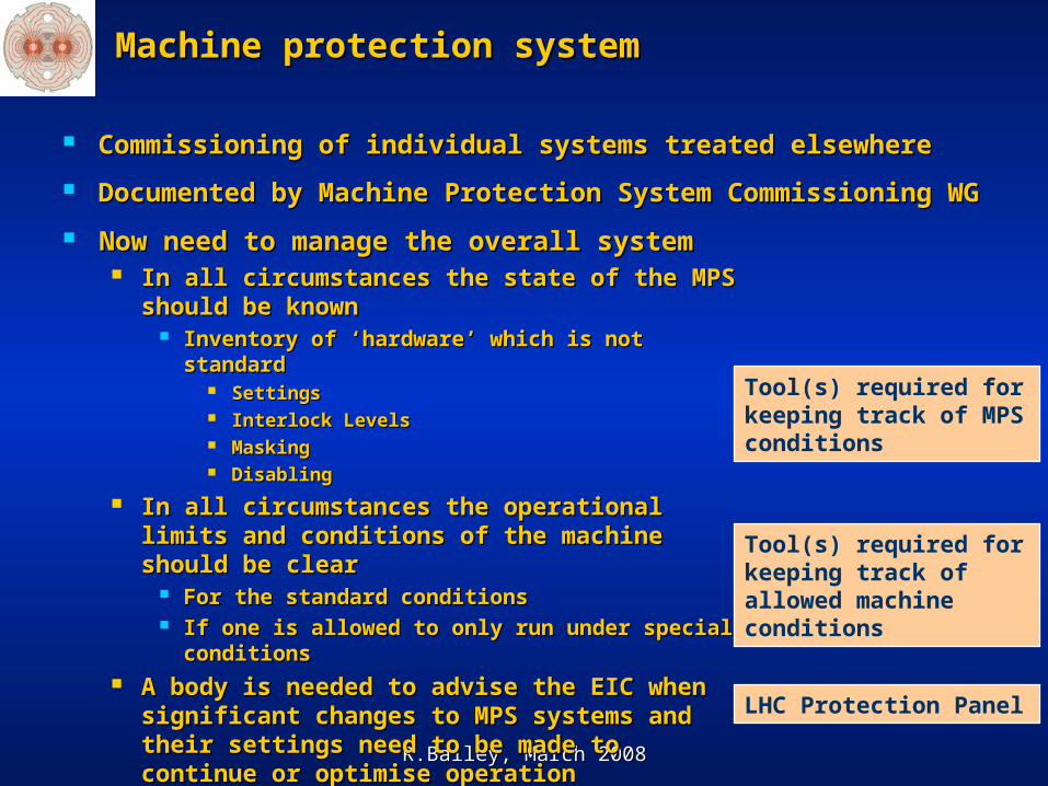
Machine protection systemMachine protection system
Commissioning of individual systems treated elsewhereCommissioning of individual systems treated elsewhere
Documented by Machine Protection System Commissioning WGDocumented by Machine Protection System Commissioning WG Now need to manage the overall system Now need to manage the overall system
In all circumstances the state of the MPS In all circumstances the state of the MPS should be knownshould be known
Inventory of ‘hardware’ which is not standardInventory of ‘hardware’ which is not standard SettingsSettings Interlock LevelsInterlock Levels MaskingMasking DisablingDisabling
In all circumstances the operational limits and In all circumstances the operational limits and conditions of the machine should be clearconditions of the machine should be clear
For the standard conditionsFor the standard conditions If one is allowed to only run under special If one is allowed to only run under special
conditionsconditions A body is needed to advise the EIC when A body is needed to advise the EIC when
significant changes to MPS systems and their significant changes to MPS systems and their settings need to be made to continue or settings need to be made to continue or optimise operationoptimise operation
Tool(s) required for keeping track of MPS conditions
Tool(s) required for keeping track of allowed machine conditions
LHC Protection Panel
R.Bailey, March 2008R.Bailey, March 2008
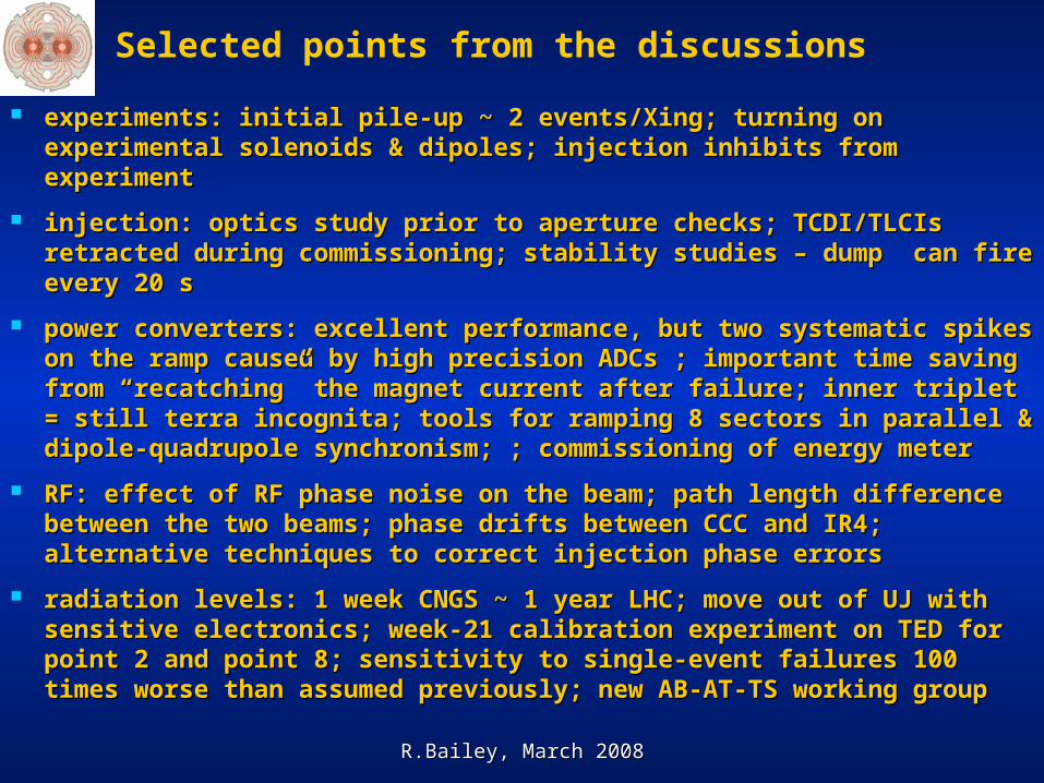
Selected points from the discussions
experiments: initial pile-up ~ 2 events/Xing; turning on experimental experiments: initial pile-up ~ 2 events/Xing; turning on experimental solenoids & dipoles; injection inhibits from experimentsolenoids & dipoles; injection inhibits from experiment
injection: optics study prior to aperture checks; TCDI/TLCIs retracted injection: optics study prior to aperture checks; TCDI/TLCIs retracted during commissioning; stability studies – dump can fire every 20 sduring commissioning; stability studies – dump can fire every 20 s
power converters: excellent performance, but two systematic spikes power converters: excellent performance, but two systematic spikes on the ramp caused by high precision ADCs ; important time saving on the ramp caused by high precision ADCs ; important time saving from “recatching” the magnet current after failure; inner triplet = still from “recatching” the magnet current after failure; inner triplet = still terra incognita; tools for ramping 8 sectors in parallel & dipole-terra incognita; tools for ramping 8 sectors in parallel & dipole-quadrupole synchronism; ; commissioning of energy meterquadrupole synchronism; ; commissioning of energy meter
RF: effect of RF phase noise on the beam; path length difference RF: effect of RF phase noise on the beam; path length difference between the two beams; phase drifts between CCC and IR4; alternative between the two beams; phase drifts between CCC and IR4; alternative techniques to correct injection phase errorstechniques to correct injection phase errors
radiation levels: 1 week CNGS ~ 1 year LHC; move out of UJ with radiation levels: 1 week CNGS ~ 1 year LHC; move out of UJ with sensitive electronics; week-21 calibration experiment on TED for point sensitive electronics; week-21 calibration experiment on TED for point 2 and point 8; sensitivity to single-event failures 100 times worse than 2 and point 8; sensitivity to single-event failures 100 times worse than assumed previously; new AB-AT-TS working group assumed previously; new AB-AT-TS working group

R.Bailey, March 2008R.Bailey, March 2008
Selected Selected points from the discussions
instrumentation: BPM polarity checks possible only with beam; BPM instrumentation: BPM polarity checks possible only with beam; BPM intensity mode has huge error (50% variation) for single bunch – so it intensity mode has huge error (50% variation) for single bunch – so it may not be useful; two monitors of beam size in store (wire scanner & may not be useful; two monitors of beam size in store (wire scanner & SLM); multi-turn acquisitions on the ramp for optics validation; BLMs SLM); multi-turn acquisitions on the ramp for optics validation; BLMs and common BPMs are only instruments sensitive to both beams; and common BPMs are only instruments sensitive to both beams; matching monitor available only for 1 beam 1 plane study only in 2008 - matching monitor available only for 1 beam 1 plane study only in 2008 - no fallback solution; resolution of screens in the dump lineno fallback solution; resolution of screens in the dump line
damper: abort gap cleaning before ramp; injection kicker rippledamper: abort gap cleaning before ramp; injection kicker ripple
collimation: periodic verification of protection hierarchy; relative cross collimation: periodic verification of protection hierarchy; relative cross calibration; monitoring of beta beating; test of cleaning efficiency with calibration; monitoring of beta beating; test of cleaning efficiency with transverse blow up? ; how to go through the squeeze without making transverse blow up? ; how to go through the squeeze without making circles with quenches and beam loss?circles with quenches and beam loss?
machine protection: “LHC Protection Panel” will make decisions; machine protection: “LHC Protection Panel” will make decisions; interlock on optics? concept of “safe” beam; damage level uncertainty interlock on optics? concept of “safe” beam; damage level uncertainty
R.Bailey, March 2008R.Bailey, March 2008
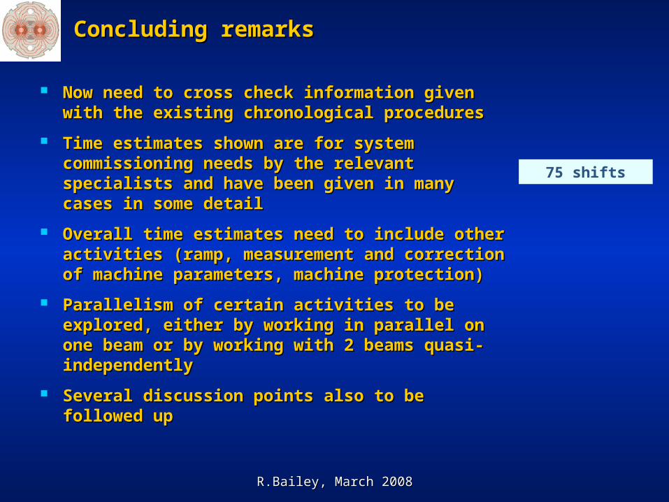
Concluding remarksConcluding remarks
Now need to cross check information given with Now need to cross check information given with the existing chronological proceduresthe existing chronological procedures
Time estimates shown are for system Time estimates shown are for system commissioning needs by the relevant specialists commissioning needs by the relevant specialists and have been given in many cases in some detailand have been given in many cases in some detail
Overall time estimates need to include other Overall time estimates need to include other activities (ramp, measurement and correction of activities (ramp, measurement and correction of machine parameters, machine protection)machine parameters, machine protection)
Parallelism of certain activities to be explored, Parallelism of certain activities to be explored, either by working in parallel on one beam or by either by working in parallel on one beam or by working with 2 beams quasi-independentlyworking with 2 beams quasi-independently
Several discussion points also to be followed upSeveral discussion points also to be followed up
75 shifts


![WELCOME []/file/BALEAP_PI… · Web viewBALEAP PIM: Process and Practice in EAP14 November 2015, University of Sheffield ELTC. BALEAP PIM: Process and Practice in EAP14 November](https://static.fdocuments.net/doc/165x107/5a7054b97f8b9aa7538beabe/welcome-wwwsheffieldacuk-filebaleappidoc-fileweb.jpg)