Ray Tracing - Computer Graphics
58
Matthias Teschner Advanced Computer Graphics Introduction
Transcript of Ray Tracing - Computer Graphics

Matthias Teschner
Advanced Computer GraphicsIntroduction

University of Freiburg – Computer Science Department – 2
Outline
Organization
Concepts
Applications
History
Selected variants
Components

University of Freiburg – Computer Science Department – 3
Contact
Matthias Teschner052 / [email protected]://cg.informatik.uni-freiburg.de/

University of Freiburg – Computer Science Department – 4
Course Information
Key course
Pattern recognition and computer graphics (rasterization)
Specialization courses
Advanced computer graphics (ray tracing)
Simulation in computer graphics (e.g., fluids)
Master project, lab course, Master thesis
Simulation track
Rendering track
University of Freiburg – Computer Science Department – 5
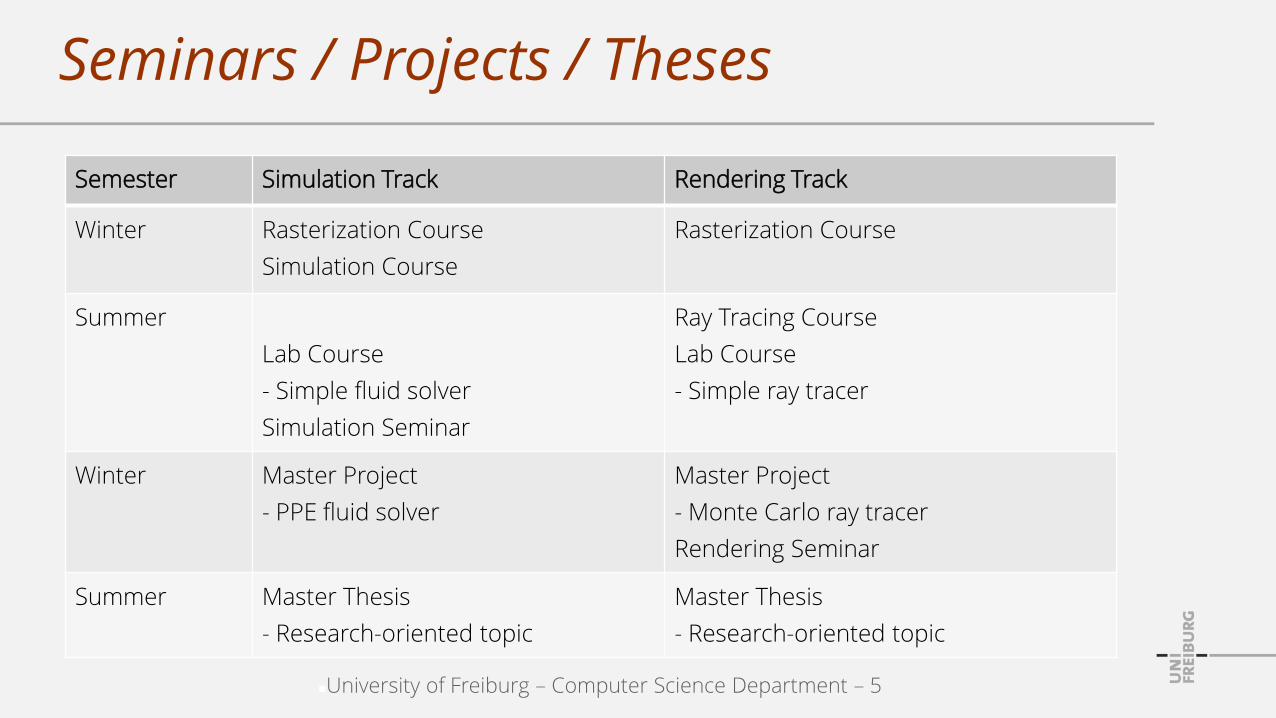
Seminars / Projects / Theses
Semester Simulation Track Rendering Track
Winter Rasterization Course
Simulation Course
Rasterization Course
Summer
Lab Course
- Simple fluid solver
Simulation Seminar
Ray Tracing Course
Lab Course
- Simple ray tracer
Winter Master Project
- PPE fluid solver
Master Project
- Monte Carlo ray tracer
Rendering Seminar
Summer Master Thesis
- Research-oriented topic
Master Thesis
- Research-oriented topic

University of Freiburg – Computer Science Department – 6
Course Goals
Ray tracing techniques
Photorealistic rendering
Global illumination techniques
Requirements:
Key course in graphics and image processing
C / C++ / C#
Basics in linear algebra

University of Freiburg – Computer Science Department – 7
Course Topics
Aspects for efficient and high-quality rendering
Radiometric quantities
Rendering equation
Monte Carlo integration
Primitives
Ray traversal / ray shooting
Sampling / antialiasing

University of Freiburg – Computer Science Department – 8
Material
Slide sets on https://cg.informatik.uni-freiburg.de/teaching.htm

University of Freiburg – Computer Science Department – 9
Material
Matt Pharr, Greg HumphreysPhysically Based RenderingMorgan Kaufmann
Kevin SuffernRay Tracing from the Ground UpA K Peters

University of Freiburg – Computer Science Department – 10
Material
Philip Dutre, Kavita Bala, Philippe BekaertAdvanced Global IlluminationA K Peters
Peter Shirley, R. Keith MorleyRealistic Ray TracingA K Peters

University of Freiburg – Computer Science Department – 11
Tutorials / Exercises
Every second Wednesday, starting on May 9
Check web page for changes
Practical exercises
Development of ray tracing components
Check web page for information andexample frameworks

University of Freiburg – Computer Science Department – 12
Outline
Organization
Concepts
Applications
History
Selected variants
Components

University of Freiburg – Computer Science Department – 13
Ray Tracing
Tracing rays through a scene to compute the radiance that is perceived by a sensor,i.e. transported along rays
Tracing a path from a camera through a pixel position of a virtual image plane to compute the color / radiance of an object that is visible along the path
[Wikipedia: Ray Tracing]

University of Freiburg – Computer Science Department – 14
Light
Is modeled as geometric rays
Travels in straight lines (e.g., no diffraction / bending)
Travels at infinite speed (steady state of light is computed)
Is emitted by light sources
Is absorbed / scattered at surfaces

University of Freiburg – Computer Science Department – 15
Measuring Light
Radiance
Characterizes strength and direction of radiation / light
Is measured by sensors
Is computed in computer-generated images
Is preserved along lines in space
Does not change with distance

University of Freiburg – Computer Science Department – 16
Light / Radiance
Light / radiancetravels along rays
Light / radianceis emitted atlight sources
Incoming light / radiance is absorbed
and scattered at surfaces
specular diffuse
Cameras capturelight / radiance
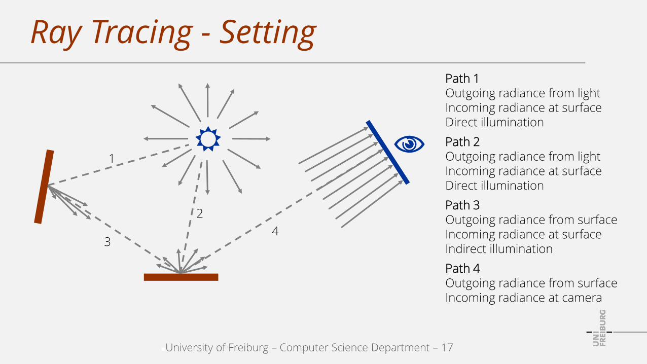
University of Freiburg – Computer Science Department – 17
Ray Tracing - SettingPath 1Outgoing radiance from lightIncoming radiance at surfaceDirect illumination
1
2
34
Path 2Outgoing radiance from lightIncoming radiance at surfaceDirect illumination
Path 3Outgoing radiance from surfaceIncoming radiance at surfaceIndirect illumination
Path 4Outgoing radiance from surfaceIncoming radiance at camera

University of Freiburg – Computer Science Department – 18
Ray Tracing - ChallengePath 4Computation of outgoing radiance from surface towards camera is the main goal of a ray tracer
1
2
34
Path 1, 2, 3 …Incoming / outgoing radiance at all other paths is requiredto compute radiance at path 4
Path 3Two surfaces illuminate each other.Outgoing radiance from q towards pdepends on outgoing radiance fromp towards q which depends on …
p
q

University of Freiburg – Computer Science Department – 19
Surfaces
Reflection properties at surfaces can be described with a function (BRDF, alternative to Phong model)
How much incident light from a particular direction is reflected into a particular direction
Incoming radiancefrom direction
Position
Outgoing radiance into direction

University of Freiburg – Computer Science Department – 20
Rendering Equation
The Rendering equation computes reflected radianceinto a particular direction given incident radiance fromall possible directions
Incoming radiancefrom direction
Position
Rendering equationOutgoing radiance into direction , e.g., towards the camera, is a sum of weighted incident radiances

University of Freiburg – Computer Science Department – 21
Ray Tracing / Rendering Equation
Ray tracers approximately solve the Rendering equation
Outgoing radiance is the sum of emitted and reflected radiance
Incident radiance - weighted with the BRDF - is integrated over the hemisphere to compute the outgoing radiance

University of Freiburg – Computer Science Department – 22
Ray Tracing / Rendering Equation
Path 4Computation of outgoing radiance from surface towards camera corresponds to solving theRendering equation
1
2
34
Path 3 Requires solving the Rendering equation
Ray tracer variants differ inthe approximation qualityof the rendering equation:The more accurate, the more expensive.
Many paths require solving the Rendering equation

University of Freiburg – Computer Science Department – 23
Towards Realistic Images
Capturing global illumination from all directionseverywhere in a scene
Less realistic images consider few and simple light sources
https://imgur.com/gallery/MXbNt

University of Freiburg – Computer Science Department – 24
Towards Realistic Images
Realistic reflection properties of materials
Surfaces are not perfectly diffuse or specular
Next Limit / Maxwell Renderhttp://support.nextlimit.com/display/maxwelldocs/IOR+files

University of Freiburg – Computer Science Department – 25
Ray Tracing - Capabilities
Reflection
Refraction
Soft shadows
Caustics
Diffuse interreflections
Specular interreflections
Depth of field
Motion blur
[sean.seanie, www.flickr.com]rendered with POVray 3.7

University of Freiburg – Computer Science Department – 26
Ray Tracing - Challenges
Ray shooting
Spatial data structures for accelerated ray shooting
Dynamic scenes are particularly challenging
Number of rays (quality vs. costs)
At ray-object intersections (solving the Rendering equation)
Per pixel (antialiasing)
Recursion depth (quality vs. costs)

University of Freiburg – Computer Science Department – 27
Outline
Organization
Concepts
Applications
History
Selected variants
Components
University of Freiburg – Computer Science Department – 28
Areas
Visual effects in movies and commercials
Major software packages have built-in ray tracers, e.g. Maya, 3ds Max (Autodesk), Houdini (Side Effects Software)
Visualization of architectural design
Consideration of realistic indoor and outdoor illumination
Automotive design
Flight and car simulators
Computer games

University of Freiburg – Computer Science Department – 29
Software
Mental ray (NVIDIA ARC)
Maxwell Render (Next Limit Technologies)
Brazil (SplutterFish)
Arnold (Solid Angle)
POV-Ray
Blender
Pbrt
Mitsuba Renderer (Wenzel Jakob)

University of Freiburg – Computer Science Department – 30
Examples
Mental ray
[www.mentalimages.com]
Mies van der Rohe Farnsworth House(Artist Alessandro Prodan)
Delta Tracing

University of Freiburg – Computer Science Department – 31
Examples
Mental ray
[www.mentalimages.com]zerone cgi GmbH and Daimler AG

University of Freiburg – Computer Science Department – 32
Examples
Spellwork Pictures
https://www.youtube.com/watch?v=DMFhM4ZfRRE

University of Freiburg – Computer Science Department – 33
Examples
Spellwork Pictures
RenderingModeling
University of Freiburg – Computer Science Department – 34
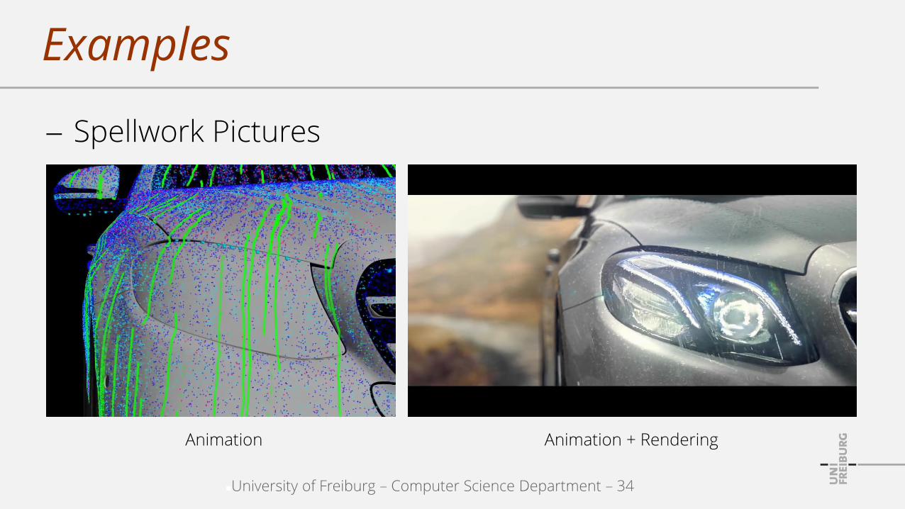
Examples
Spellwork Pictures
Animation Animation + Rendering

University of Freiburg – Computer Science Department – 35
Examples
Spellwork Pictures
University of Freiburg – Computer Science Department – 36
Outline
Organization
Concepts
Applications
History
Selected variants
Components

University of Freiburg – Computer Science Department – 37
Photorealistic Rendering
Rasterization 1965: rasterized lines (Bresenham)
1967: rasterized flat-shaded polygons (Wylie)
1971: Gouraud shading
1973: Phong illumination model
1974: texture mapping (Blinn)
1974: depth buffer (Catmull)
1975: Phong shading
1977: shadow volumes (Crow)
1978: shadow maps (Williams)

University of Freiburg – Computer Science Department – 38
Photorealistic Rendering
Ray tracing 1968: viewing and shadow rays, non-recursive (Appel)
Recursive ray tracing 1980: ideal reflection, refraction (Whitted)
Rendering equation 1986: general description of light distribution (Kajiya)
-- Arbitrary global illumination effects can be considered
Distribution ray tracing 1986: Monte-Carlo evaluation of integrals (Cook) Approximately solves the Rendering equation
University of Freiburg – Computer Science Department – 39
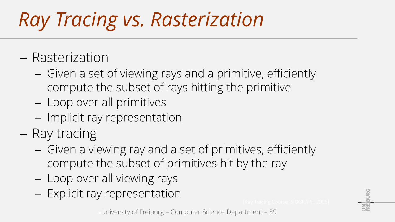
Ray Tracing vs. Rasterization
Rasterization Given a set of viewing rays and a primitive, efficiently
compute the subset of rays hitting the primitive
Loop over all primitives
Implicit ray representation
Ray tracing Given a viewing ray and a set of primitives, efficiently
compute the subset of primitives hit by the ray
Loop over all viewing rays
Explicit ray representation[Ray Tracing Course: SIGGRAPH 2005]
University of Freiburg – Computer Science Department – 40
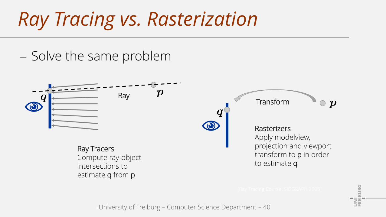
Ray Tracing vs. Rasterization
Solve the same problem
[Ray Tracing Course: SIGGRAPH 2005]
Ray TracersCompute ray-object intersections to estimate q from p
Rasterizers
Apply modelview,projection and viewporttransform to p in orderto estimate q
TransformRay

University of Freiburg – Computer Science Department – 41
Ray Tracing vs. Rasterization
Rasterization
Well-established, parallelizable algorithms
Popular in interactive applications
Specialized realizations of global illumination effects
Ray tracing
Natural incorporation of numerous visual effects
Unified algorithms for global illumination effects
Trade-off between quality and performance

University of Freiburg – Computer Science Department – 42
Outline
Organization
Concepts
Applications
History
Selected variants
Components

University of Freiburg – Computer Science Department – 43
Ray Tracing
Ray generation
Ray traversal
Intersection
Shading
Frame buffer
camera
light light
viewing / camera / primary ray
shadow rays
Viewing rays return a radiance value.Shadow rays return an occlusion valuewhich is also a radiance.

University of Freiburg – Computer Science Department – 44
Ray Tracing
Arthur Appel: Some techniques for shading machinerenderings of solids, 1968.

University of Freiburg – Computer Science Department – 45
Recursive Ray Tracing
Ray generation
Ray traversal
Intersection
Shading
Frame buffer
specularmaterial
diffusematerialcamera
light light
viewing / camera / primary ray
reflectionray
shadow rays
Viewing rays return a radiance.Shadow rays return an occlusion / radiance.Reflection and refraction rays return a radiance.

University of Freiburg – Computer Science Department – 46
Recursive Ray Tracing
Turner Whitted: An Improved Illumination Model for Shaded Display, 1980.

University of Freiburg – Computer Science Department – 47
Distribution Ray Tracing (Stochastic Ray Tracing)
Consider more than one randomly perturbed reflection / refraction ray at a surface point, e.g.
Incoming radiancefrom direction
Position
Rendering equationOutgoing radiance into direction , e.g., towards the camera, is a sum of weighted incident radiances

University of Freiburg – Computer Science Department – 48
Distribution Ray Tracing (Stochastic Ray Tracing)
Examples
Distributing rays over the hemisphereto capture the incident radiance (Monte Carlo integration for solving the rendering equation)
Shadow rays over an area light source for soft shadows
Perturbing ray origins to enable depth-of-field effects
Rays per pixel over time to get motion blur effects

University of Freiburg – Computer Science Department – 49
Distribution Ray Tracing
Robert Cook, Thomas Porter, Loren Carpenter: Distributed Ray Tracing, 1984.

University of Freiburg – Computer Science Department – 50
Outline
Organization
Concepts
Applications
History
Selected variants
Components

University of Freiburg – Computer Science Department – 51
Overview
Camera generates viewing rays
Location and radiant intensity of light sources
Ray-object intersections
Visibility of light sources
Surface scattering model
Recursion
Participating media

University of Freiburg – Computer Science Department – 52
Camera
Generates viewing rays
Pinhole camera with a virtual image plane (near plane) in front of the pinhole
Pinhole is referred to as the eye
For a position on the image, a camera simulator generates rays along which light is known to contribute to that position, e.g.
A ray from the eye through the image position
A ray that considers one or multiple lenses

University of Freiburg – Computer Science Department – 53
Light Distribution
Determining the amount of light energy arrivingat the differential area around the intersection point
Therefore, geometric and radiometric distribution of light has to be known
For emitted light from point light sources
For emitted light from area light sources
For reflected light for object surfaces

University of Freiburg – Computer Science Department – 54
Ray-Object Intersection
Determine whether a ray intersects an object
Determine the first intersection (closest to the ray origin)
Determine further geometric information, e.g.
Surface normal
Partial derivatives of position and normal with respect to the local surface parameterization
Efficient implementations heavily rely on spatial data structures

University of Freiburg – Computer Science Department – 55
Visibility
Determine whether a light source is visible from a surface point to be shaded
Shadow rays are casted from the object to the light source
If the distance to the first ray-object intersectionalong this ray is shorter than the distance to the light source, the surface point is in shadow

University of Freiburg – Computer Science Department – 56
Surface Scattering
Computes radiance scattered back along a viewing ray
From previous components, we have
Ray-object intersection and further geometric information
Information on incident lighting
We further know appearance properties, e.g.
A local illumination model
A Bidirectional Reflectance Distribution Function BRDF(how much light is reflected from an incoming direction to an outgoing direction)

University of Freiburg – Computer Science Department – 57
Recursion
Recursively invoke the ray-tracing components
If, e.g., a viewing ray hits a mirror
The viewing ray can be reflected at the mirror
The ray-tracing routine is applied to the reflected ray
The resulting radiance is considered as additionalillumination of the mirror
To approximately solve the rendering equation,
Various rays are generated that sample the hemisphere above the surface (Monte Carlo integration)
University of Freiburg – Computer Science Department – 58
Participating Media
E.g., smoke, fog, dust
In vacuum, radiance along a ray does not change
In presence of participating media, light can be attenuated or extinguished by scattering it in different directions
Participating media can be characterized by its transmittance