Rational Design of a Trifunctional Binder for Hard Carbon ...
11
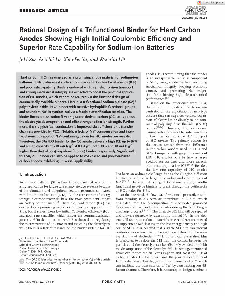
www.afm-journal.de © 2021 Wiley-VCH GmbH 2104137 (1 of 11) RESEARCH ARTICLE Rational Design of a Trifunctional Binder for Hard Carbon Anodes Showing High Initial Coulombic Efficiency and Superior Rate Capability for Sodium-Ion Batteries Ji-Li Xia, An-Hui Lu, Xiao-Fei Yu, and Wen-Cui Li* Hard carbon (HC) has emerged as a promising anode material for sodium-ion batteries (SIBs), whereas it suffers from low initial Coulombic efficiency (ICE) and poor rate capability. Binders endowed with high electron/ion transport and strong mechanical integrity are expected to boost the practical applica- tion of HC anodes, which cannot be realized via the functional design of commercially available binders. Herein, a trifunctional sodium alginate (SA)/ polyethylene oxide (PEO) binder with massive hydrophilic functional groups and abundant Na + is synthesized via a feasible esterification reaction. The binder forms a passivation film on glucose-derived carbon (GC) to suppress the electrolyte decomposition and offer stronger adhesion strength. Further- more, the sluggish Na + conduction is improved via sufficient ionic transfer channels provided by PEO. Notably, effects of Na + compensation and inter- facial ionic transport of Na + -containing binder for HC anodes are revealed. Therefore, the SA/PEO binder for the GC anode delivers a high ICE up to 87% and a high capacity of 270 mA h g −1 at 0.1 A g −1 , both 10% and 80 mA h g −1 higher than that of poly(vinylidene fluoride) binder, respectively. Significantly, this SA/PEO binder can also be applied to coal-based and polymer-based carbon anodes, exhibiting universal applicability. DOI: 10.1002/adfm.202104137 J.-L. Xia, Prof. A.-H. Lu, X.-F. Yu, Prof. W.-C. Li State Key Laboratory of Fine Chemicals School of Chemical Engineering Dalian University of Technology Dalian 116024, P. R. China E-mail: [email protected] The ORCID identification number(s) for the author(s) of this article can be found under https://doi.org/10.1002/adfm.202104137. anodes. It is worth noting that the binder is an indispensable and vital component of SIBs, being conducive to maintaining mechanical integrity, keeping electronic contact, and promoting Na + migra- tion for achieving high electrochemical performance. [8,9] Based on the experience from LIBs, the utilization of binders in SIBs are con- centrated on the exploitation of new-type binders that can suppress volume expan- sion of electrodes or directly using com- mercial poly(vinylidene fluoride) (PVDF) binder. [10–16] However, the experience cannot solve irreversible side reactions at the interface and slow Na + transport of HC anodes. The primary reason for the issues derives from the difference in the carbon anodes used in LIBs and SIBs. Compared with graphite anodes of LIBs, HC anodes of SIBs have a larger specific surface area and more defects, often resulting in a low ICE. [17–19] Besides, the low rate capability of HC anodes has been an arduous challenge due to the sluggish diffusion kinetics caused by the large ionic radius and atomic mass of Na + . [20–22] Therefore, it is urgent to rationally design multi- functional new-type binders to break through the bottlenecks of HC anodes for SIBs. On the one hand, the low ICE of HC anode primarily results from forming solid electrolyte interphase (SEI) film, which originated from the decomposition of electrolytes promoted by exposed surface and defective sites during the first charge– discharge process. [14,23,24] The unstable SEI film will be repaired and grown repeatedly by consuming limited Na + in the elec- trode. Thus, more cathode materials or electrolytes are needed to supplement Na + , leading to the low energy density and high cost of SIBs. It is believed that a stable SEI film can prevent continuous side reactions of the electrode materials and ensure the stability of electrodes. [25–27] If an artificial passivation film is fabricated to replace the SEI film, the contact between the particles and the electrolyte can be effectively avoided to inhibit the decomposition of the electrolyte. [28] The strategy mentioned above can reduce the Na + consumption and boost the ICE of carbon anodes. On the other hand, the poor rate capability of HC anodes owe to the sluggish diffusion kinetics of Na + , which can facilitate the transmission of Na + by constructing ion dif- fusion channels. Therefore, it is necessary to design a suitable 1. Introduction Sodium-ion batteries (SIBs) have been considered as a prom- ising application for large-scale energy storage systems because of the abundant and ubiquitous sodium resources compared with lithium-ion batteries (LIBs). As the core carrier of energy storage, electrode materials have the most prominent impact on battery performance. [1–5] Thereinto, hard carbon (HC) has emerged as a promising anode for the practical application of SIBs, but it suffers from low initial Coulombic efficiency (ICE) and poor rate capability, which hinder the commercialization process. [6,7] To date, most research has focused on regulating the microstructure of HC anodes and matching the electrolytes, while there is a lack of research on the binder suitable for HC Adv. Funct. Mater. 2021, 2104137
Transcript of Rational Design of a Trifunctional Binder for Hard Carbon ...
www.afm-journal.de
© 2021 Wiley-VCH GmbH2104137 (1 of 11)
ReseaRch aRticle
Rational Design of a Trifunctional Binder for Hard Carbon Anodes Showing High Initial Coulombic Efficiency and Superior Rate Capability for Sodium-Ion Batteries
Ji-Li Xia, An-Hui Lu, Xiao-Fei Yu, and Wen-Cui Li*
Hard carbon (HC) has emerged as a promising anode material for sodium-ion batteries (SIBs), whereas it suffers from low initial Coulombic efficiency (ICE) and poor rate capability. Binders endowed with high electron/ion transport and strong mechanical integrity are expected to boost the practical applica-tion of HC anodes, which cannot be realized via the functional design of commercially available binders. Herein, a trifunctional sodium alginate (SA)/polyethylene oxide (PEO) binder with massive hydrophilic functional groups and abundant Na+ is synthesized via a feasible esterification reaction. The binder forms a passivation film on glucose-derived carbon (GC) to suppress the electrolyte decomposition and offer stronger adhesion strength. Further-more, the sluggish Na+ conduction is improved via sufficient ionic transfer channels provided by PEO. Notably, effects of Na+ compensation and inter-facial ionic transport of Na+-containing binder for HC anodes are revealed. Therefore, the SA/PEO binder for the GC anode delivers a high ICE up to 87% and a high capacity of 270 mA h g−1 at 0.1 A g−1, both 10% and 80 mA h g−1 higher than that of poly(vinylidene fluoride) binder, respectively. Significantly, this SA/PEO binder can also be applied to coal-based and polymer-based carbon anodes, exhibiting universal applicability.
DOI: 10.1002/adfm.202104137
J.-L. Xia, Prof. A.-H. Lu, X.-F. Yu, Prof. W.-C. LiState Key Laboratory of Fine ChemicalsSchool of Chemical EngineeringDalian University of TechnologyDalian 116024, P. R. ChinaE-mail: [email protected]
The ORCID identification number(s) for the author(s) of this article can be found under https://doi.org/10.1002/adfm.202104137.
anodes. It is worth noting that the binder is an indispensable and vital component of SIBs, being conducive to maintaining mechanical integrity, keeping electronic contact, and promoting Na+ migra-tion for achieving high electrochemical performance.[8,9]
Based on the experience from LIBs, the utilization of binders in SIBs are con-centrated on the exploitation of new-type binders that can suppress volume expan-sion of electrodes or directly using com-mercial poly(vinylidene fluoride) (PVDF) binder.[10–16] However, the experience cannot solve irreversible side reactions at the interface and slow Na+ transport of HC anodes. The primary reason for the issues derives from the difference in the carbon anodes used in LIBs and SIBs. Compared with graphite anodes of LIBs, HC anodes of SIBs have a larger specific surface area and more defects, often resulting in a low ICE.[17–19] Besides, the low rate capability of HC anodes
has been an arduous challenge due to the sluggish diffusion kinetics caused by the large ionic radius and atomic mass of Na+.[20–22] Therefore, it is urgent to rationally design multi-functional new-type binders to break through the bottlenecks of HC anodes for SIBs.
On the one hand, the low ICE of HC anode primarily results from forming solid electrolyte interphase (SEI) film, which originated from the decomposition of electrolytes promoted by exposed surface and defective sites during the first charge–discharge process.[14,23,24] The unstable SEI film will be repaired and grown repeatedly by consuming limited Na+ in the elec-trode. Thus, more cathode materials or electrolytes are needed to supplement Na+, leading to the low energy density and high cost of SIBs. It is believed that a stable SEI film can prevent continuous side reactions of the electrode materials and ensure the stability of electrodes.[25–27] If an artificial passivation film is fabricated to replace the SEI film, the contact between the particles and the electrolyte can be effectively avoided to inhibit the decomposition of the electrolyte.[28] The strategy mentioned above can reduce the Na+ consumption and boost the ICE of carbon anodes. On the other hand, the poor rate capability of HC anodes owe to the sluggish diffusion kinetics of Na+, which can facilitate the transmission of Na+ by constructing ion dif-fusion channels. Therefore, it is necessary to design a suitable
1. Introduction
Sodium-ion batteries (SIBs) have been considered as a prom-ising application for large-scale energy storage systems because of the abundant and ubiquitous sodium resources compared with lithium-ion batteries (LIBs). As the core carrier of energy storage, electrode materials have the most prominent impact on battery performance.[1–5] Thereinto, hard carbon (HC) has emerged as a promising anode for the practical application of SIBs, but it suffers from low initial Coulombic efficiency (ICE) and poor rate capability, which hinder the commercialization process.[6,7] To date, most research has focused on regulating the microstructure of HC anodes and matching the electrolytes, while there is a lack of research on the binder suitable for HC
Adv. Funct. Mater. 2021, 2104137
www.afm-journal.dewww.advancedsciencenews.com
2104137 (2 of 11) © 2021 Wiley-VCH GmbH
binder to form a passivating film possessing ion transport channels on the electrode surface.
Water-soluble binders (poly(acrylic acid) series,[29,30] alginic acid series,[31–34] carboxymethylcellulose series,[29,35] chitosan series,[36,37] and natural gum series[38,39]) have a large amount of hydrophilic functional groups (COOH, OH, etc.) com-pared to the PVDF binder with chemically inactive HF bonds in the main chain.[40] Hydrophilic functional groups can form strong hydrogen bonds, ion-dipole bonds, and chemical bonds with metal/silicon oxides and active silica particles to improve adhesion strength and uniformly cover the electrode surface to avoid side reactions.[9,41–43] Drawing lessons from experience, it is necessary to adjust and screen the functional groups on the surface of the HC anodes to build a passivation film. Because HC anodes and the sodium alginate (SA) binder contain hydroxyl and carboxyl groups, it is possible to form a uniform passivation film through hydrogen bonding or esterification between functional groups. Furthermore, the SA binder with abundant carboxyl groups has electrostatic repulsion reducing the agglomeration effect between small molecules, which is expected to make the binder easily wetted, thus uniformly covering the surface of carbon particles. However, the uni-form passivation film lacks effective ion diffusion paths, which reduces the ion transfer rate from the interface to the inte-rior of carbon particles.[8] To overcome this issue, we envisage designing the molecular structure of binders to improve the inherent sluggish kinetics of Na+ by providing directional trans-mission paths, which convert the ion transport from disorder into order. Therefore, introducing an ionic binder into the SA binder is expected to improve Na+ conduction during the charge–discharge process.
In this work, a trifunctional SA/polyethylene oxide (PEO) binder is successfully prepared by an esterification reaction to improve the ICE and the rate capability of HC anodes. There-into, SA can form a passivating film on the carbon particles possessing strong mechanical strength to prevent continuous side reactions. Moreover, the introduction of ionic PEO can significantly improve the interfacial Na+ migration, which is transferred to hydroxy groups with the peristaltic movement of the PEO binder. Meanwhile, a pre-sodiation strategy is pro-posed to compensate Na+ loss caused by the formation of SEI film. When glucose-derived carbon (GC) is used as the anode, the SA/PEO binder exhibits a high capacity (336.5 mA h g−1 at 0.02 A g−1), excellent rate performance (270 mA h g−1 at 0.1 A g−1), and a high ICE (87%), significantly improving the ICE and the rate capability of HC anodes. We demonstrate that the trifunctional SA/PEO binder can also be widely applied to various types of HC anodes, showing its universal applicability. Our findings provide a new perspective on the design of the molecular structure of multifunctional binder and deeply shed light on the charge compensation mechanism and interfacial ionic transport mechanism of Na+-containing binder on the SEI film of HC anodes of SIBs.
2. Results and Discussion
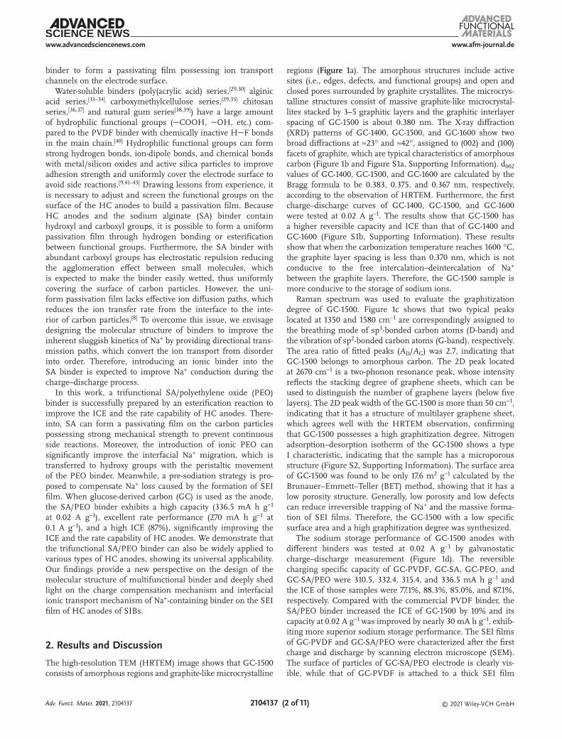
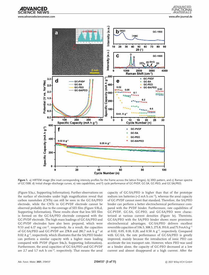
The high-resolution TEM (HRTEM) image shows that GC-1500 consists of amorphous regions and graphite-like microcrystalline
regions (Figure 1a). The amorphous structures include active sites (i.e., edges, defects, and functional groups) and open and closed pores surrounded by graphite crystallites. The microcrys-talline structures consist of massive graphite-like microcrystal-lites stacked by 3–5 graphitic layers and the graphitic interlayer spacing of GC-1500 is about 0.380 nm. The X-ray diffraction (XRD) patterns of GC-1400, GC-1500, and GC-1600 show two broad diffractions at ≈23° and ≈42°, assigned to (002) and (100) facets of graphite, which are typical characteristics of amorphous carbon (Figure 1b and Figure S1a, Supporting Information). d002 values of GC-1400, GC-1500, and GC-1600 are calculated by the Bragg formula to be 0.383, 0.375, and 0.367 nm, respectively, according to the observation of HRTEM. Furthermore, the first charge–discharge curves of GC-1400, GC-1500, and GC-1600 were tested at 0.02 A g−1. The results show that GC-1500 has a higher reversible capacity and ICE than that of GC-1400 and GC-1600 (Figure S1b, Supporting Information). These results show that when the carbonization temperature reaches 1600 °C, the graphite layer spacing is less than 0.370 nm, which is not conducive to the free intercalation–deintercalation of Na+ between the graphite layers. Therefore, the GC-1500 sample is more conducive to the storage of sodium ions.
Raman spectrum was used to evaluate the graphitization degree of GC-1500. Figure 1c shows that two typical peaks located at 1350 and 1580 cm−1 are correspondingly assigned to the breathing mode of sp3-bonded carbon atoms (D-band) and the vibration of sp2-bonded carbon atoms (G-band), respectively. The area ratio of fitted peaks (AD/AG) was 2.7, indicating that GC-1500 belongs to amorphous carbon. The 2D peak located at 2670 cm−1 is a two-phonon resonance peak, whose intensity reflects the stacking degree of graphene sheets, which can be used to distinguish the number of graphene layers (below five layers). The 2D peak width of the GC-1500 is more than 50 cm−1, indicating that it has a structure of multilayer graphene sheet, which agrees well with the HRTEM observation, confirming that GC-1500 possesses a high graphitization degree. Nitrogen adsorption–desorption isotherm of the GC-1500 shows a type I characteristic, indicating that the sample has a microporous structure (Figure S2, Supporting Information). The surface area of GC-1500 was found to be only 17.6 m2 g−1 calculated by the Brunauer–Emmett–Teller (BET) method, showing that it has a low porosity structure. Generally, low porosity and low defects can reduce irreversible trapping of Na+ and the massive forma-tion of SEI films. Therefore, the GC-1500 with a low specific surface area and a high graphitization degree was synthesized.
The sodium storage performance of GC-1500 anodes with different binders was tested at 0.02 A g−1 by galvanostatic charge–discharge measurement (Figure 1d). The reversible charging specific capacity of GC-PVDF, GC-SA, GC-PEO, and GC-SA/PEO were 310.5, 332.4, 315.4, and 336.5 mA h g−1 and the ICE of those samples were 77.1%, 88.3%, 85.0%, and 87.1%, respectively. Compared with the commercial PVDF binder, the SA/PEO binder increased the ICE of GC-1500 by 10% and its capacity at 0.02 A g−1 was improved by nearly 30 mA h g−1, exhib-iting more superior sodium storage performance. The SEI films of GC-PVDF and GC-SA/PEO were characterized after the first charge and discharge by scanning electron microscope (SEM). The surface of particles of GC-SA/PEO electrode is clearly vis-ible, while that of GC-PVDF is attached to a thick SEI film
Adv. Funct. Mater. 2021, 2104137
www.afm-journal.dewww.advancedsciencenews.com
2104137 (3 of 11) © 2021 Wiley-VCH GmbH
(Figure S3a,c, Supporting Information). Further observations on the surface of electrodes under high magnification reveal that carbon nanotubes (CNTs) can still be seen in the GC-SA/PEO electrode, while the CNTs in GC-PVDF electrode cannot be observed probably due to the coverage of SEI film (Figure S3b,d, Supporting Information). These results show that less SEI film is formed on the GC-SA/PEO electrode compared with the GC-PVDF electrode. The high mass loadings of GC-SA/PEO and GC-PVDF electrodes have also been prepared, which were 9.53 and 6.17 mg cm−2, respectively. As a result, the capacities of GC-SA/PEO and GC-PVDF are 278.8 and 281.7 mA h g−1 at 0.02 A g−1, respectively, which illustrates that the SA/PEO binder can perform a similar capacity with a higher mass loading compared with PVDF (Figure S4a,b, Supporting Information). Furthermore, the areal capacities of GC-SA/PEO and GC-PVDF are 2.7 and 1.7 mA h cm−2, respectively. That means the areal
capacity of GC-SA/PEO is higher than that of the prototype sodium ion batteries (≈2 mA h cm−2), whereas the areal capacity of GC-PVDF cannot meet that standard. Therefore, the SA/PEO binder can perform a better electrochemical performance com-pared with the PVDF binder. Furthermore, rate capabilities of GC-PVDF, GC-SA, GC-PEO, and GC-SA/PEO were charac-terized at various current densities (Figure 1e). Thereinto, GC-SA/PEO with the SA/PEO binder shows more prominent electrochemical advantages. GC-SA/PEO delivers excellent reversible capacities of 336.5, 308.5, 275.8, 193.0, and 75.9 mA h g−1 at 0.02, 0.05, 0.10, 0.20, and 0.50 A g−1, respectively. Compared with GC-SA, the rate performance of GC-SA/PEO is greatly improved, mainly because the introduction of ionic PEO can accelerate the ion transport rate. However, when PEO was used as a binder alone, the capacity of GC-PEO decreased at a low current and almost disappeared at a high current. After the
Figure 1. a) HRTEM image (the inset corresponding intensity profiles for the frame across the lattice fringes), b) XRD pattern, and c) Raman spectra of GC-1500. d) Initial charge–discharge curves, e) rate capabilities, and f) cycle performance of GC-PVDF, GC-SA, GC-PEO, and GC-SA/PEO.
Adv. Funct. Mater. 2021, 2104137
www.afm-journal.dewww.advancedsciencenews.com
2104137 (4 of 11) © 2021 Wiley-VCH GmbH
current returned to low, the capacity cannot be restored, indi-cating that the stability of GC-PEO is inferior. It is believed that gelation tendency and electrochemical instability of PEO limit the cycle stability of electrodes during the charge–discharge process.[44–46] In addition, at current densities of 0.02, 0.05, 0.10, 0.20, and 0.50 A g−1, GC-PVDF shows 307.6, 269.7, 196.7, 98.3, and 59.9 mA h g−1, respectively. Thereinto, the reversible specific capacity of GC-SA/PEO is 80 mA h g−1 higher than that of GC-PVDF at 0.10 A g−1 and even close to 100 mA h g−1 at 0.20 A g−1, which shows a higher rate performance of GC-SA/PEO. For HC anodes, it has been a challenge to strike a balance between the rate capability and ICE, which should be both considered. Impressively, the dramatic improvement of electrochemical per-formance is a big surprise when the mass fraction of the binder is only 10 wt% for the GC-1500 electrode. The significant effect of the binder is likely originated from its cross-linking structure and the bond composition, reducing the formation of SEI film and improving the ion transmission.
The electrochemical characteristics of GC-PVDF, GC-PEO, GC-SA, and GC-SA/PEO electrodes were further tested by cyclic voltammetry (CV) measurements at 0.1 mV s−1. CV curves of the electrodes with different binders at the first five cycles in the voltage range of 0.01–3.00 V are revealed in Figure S5a–d, Supporting Information. It can be seen that in the first cycle of four binders, an irreversible reduction peak appears around 0.5 V, which mainly corresponds to the forma-tion of SEI film and the decomposition of electrolyte on the material surface. The redox peaks at about 0.01 and 0.1 V corre-sponding to the insertion–deinsertion of Na+ between graphite layers and pores filling, respectively. The CV curves match well in subsequent cycles of GC-SA/PEO, indicating the good cycle reversibility. In addition, the current density of the peak repre-sents the reaction rate, and the higher the current density of peak is, the faster the reaction will be. The current densities of redox peaks of GC-PEO and GC-SA/PEO were higher, followed by GC-SA and GC-PVDF. Furthermore, the galvanostatic inter-mittent titration technique (GITT) and electrochemical imped-ance spectroscopy (EIS) were also tested to explore the effect of different binders on the sodium storage behavior of GC-1500 during the charge–discharge process. Compared with GC-PVDF, GITT potential profiles on the potential platform show that the capacity of GC-SA/PEO is increased (Figure S6a,b, Supporting Information), and the ion diffusion coefficient of GC-SA/PEO has higher (Figure S6c,d, Supporting Informa-tion). EIS curves show that GC-SA/PEO has the lowest reaction impedance compared with other electrodes (Figure S7, Sup-porting Information). Therefore, the sodium storage processes of GC-SA/PEO electrodes at 0.1 V are more likely to occur, indicating that the reaction rate originated from the addition of ionically conductive PEO groups. It is mainly believed that ionic PEO binder can provide effective channels for the trans-mission of Na ions, which is in favor of improving the ions diffusion rate.
Furthermore, the structural stability of the samples was further confirmed by the cyclic performance (Figure 1f). After 100 cycles, the reversible capacity and capacity retention rate of GC-SA/PEO samples are 268.4 mA h g−1 and 90%, respectively, both higher than that of GC-PVDF at 0.05 A g−1 (211.9 mA h g−1 and 73%). Therefore, GC-SA/PEO shows excellent cycle stability in
comparison with other samples. In a word, these results show that the novel GC-SA/PEO binder can decrease the loss of irreversible capacity during the initial charge–discharge process and facilitate Na+ transmission, improving the rate capability and maintaining a stable structure during the long-term cycles. The design of the SA/PEO composite binder not only maintains the electrochemical stability of PEO but also improves the ability of transport ions of SA. Therefore, the electrode with the SA/PEO binder can obtain advanced rate capability and electrochemical stability.
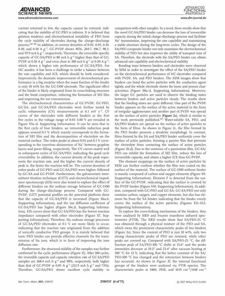
Bonding ways between binders and electrodes were observed by SEM in order to investigate the effect of the SA/PEO binder on the electrochemical performance of HC electrodes compared with PVDF, SA, and PEO binders. The SEM images show that binders can bond the active particles with the conductive agent tightly, and the whole electrode shows the loose and porous char-acteristics (Figure S8a–d, Supporting Information). Moreover, the larger GC particles are used to observe the binding states between binders and active particles clearly. The results show that the binding states are quite different. One part of the PVDF binder appears on the surface of the active material in the form of irregular agglomerates and another part of PVDF was spread on the surface of active particles (Figure 2a), which is similar to the work previously published.[47] Water-soluble SA, PEO, and SA/PEO binders are spread on the surface of active particles in the form of films. As shown in Figure 2c, the film formed by the PEO binder presents a dendritic morphology. In contrast, films formed by the SA and SA/PEO binder uniformly cover the surface of active particles, forming a passive film that prevents the electrolyte from contacting the surface of active particles (Figure 2b,d). Due to the existence of a passivation film, GC-SA/PEO can inhibit the formation of SEI film, reduce the loss of irreversible capacity, and obtain a higher ICE than GC-PVDF.
The element mappings on the surface of active particles by SEM can further confirm whether the film was coated on the surface of the material. The surface of GC-1500 without binder is mainly composed of carbon and oxygen elements (Figure S9, Supporting Information). Element F is detected from the sur-face of the GC-PVDF, indicating that the surface is covered by the PVDF binder (Figure S10, Supporting Information). In addi-tion, compared with GC-PEO and GC-SA, GC-SA/PEO not only contains carbon, oxygen, and copper elements, but also has ele-ment Na from the SA binder, indicating that the binder evenly covers the surface of the active particles (Figures S11–S13, Supporting Information).
To explore the cross-linking mechanism of the binders, they were analyzed by XRD and Fourier transform infrared spec-trometer (FTIR). The XRD results show that SA/PEO-25 °C was obtained through a physical mixture of the PEO and SA, which owns the prominent characteristic peaks of two binders (Figure 2e). Since the content of PEO is just 10 wt%, only two strong characteristic peaks of PEO are retained, while other peaks are covered up. Compared with SA/PEO-25 °C, the dif-fraction peak of SA/PEO-100 °C shifts at 15.6° and the peaks intensities decrease at 19.2° and 23.4° after vacuum heating at 100 °C for 12 h, indicating that the lattice constant of the SA/PEO-100 °C has changed and the interaction between binders has occurred. As shown in Figure 2f, the internal functional groups of the binders were analyzed via FTIR spectra. The characteristic peaks at 3460, 2926, and 1619 cm−1/1418 cm−1
Adv. Funct. Mater. 2021, 2104137
www.afm-journal.dewww.advancedsciencenews.com
2104137 (5 of 11) © 2021 Wiley-VCH GmbH
could be assigned to OH stretching, CH stretching, and OCONa, respectively, which illustrates SA/PEO-25 °C and SA/PEO-100 °C binders both maintain the characteristics peaks of SA. It is worth noting that a new ester group peak of
the SA/PEO-100 °C appears near 1730 cm−1, which can further prove the formation of ester groups (OCO) due to the esteri-fication reaction between SA and PEO. The distribution of functional groups on the surface of GC-1500 was obtained by
Figure 2. SEM images of a) GC-PVDF, b) GC-SA, c) GC-PEO, and d) GC-SA/PEO. e) XRD patterns and f) FTIR spectra of PEO, SA, SA/PEO-25 °C, and SA/PEO-100 °C. g) Schematic diagram of synthetic process for cross-liked SA/PEO binder.
Adv. Funct. Mater. 2021, 2104137
www.afm-journal.dewww.advancedsciencenews.com
2104137 (6 of 11) © 2021 Wiley-VCH GmbH
X-ray photoelectron spectroscopy (XPS). The results show that GC-1500 contains hydroxyl and carboxyl groups, which provides a prerequisite for forming hydrogen bonds between the surface of GC-1500 and the SA/PEO binder (Figure S14, Supporting Information). FTIR was further used to determine the interac-tion between GC-1500 and the SA/PEO binder. The results show that the characteristic peak of the CO on GC-1500 appears at 1637 cm−1, and it shifts to a lower wavenumber of 1617 cm−1 in the spectrum of GC-SA/PEO, indicating that there are hydrogen bonds in the GC-SA/PEO, which can form a passive film on the surface of active particles (Figure S15, Supporting Information). The polar functional groups on the surface of GC-1500 can form hydrogen bonds with the hydrophilic group of the binder. On the one hand, it is beneficial to the formation of passivation film similar as SEI film. On the other hand, the binding effect of polar groups on the surface of hard carbon on Na+ is weakened, so the ICE is also improved. Therefore, the adhesion strength of the passive film provided by hydrogen bonds is stronger than that of PVDF via the mechanical inter-lock between the binder and carbon particles. The cross-linking mechanism of SA/PEO is shown in Figure 2g. After dissolving the SA and PEO into an aqueous solution, COONa groups are converted into COOH, generating NaOH due to the hydro-lyzation of SA. The solution is alkaline, which can provide preparatory conditions for a future esterification reaction. The cross-linked SA/PEO binder was synthesized via an in-situ esterification reaction between SA and PEO during the prepara-tion of the electrode. The esterification reaction between OH on PEO and COOH on SA was undergone at 100 °C under vacuum heating, producing ester groups. Actually, the number of hydroxyl groups at both ends and molecular weight of PEO will affect the degree of esterification. It is generally believed that with the increase of molecular weight of PEO, the interac-tion between the hydroxyl groups at both ends would become weaker, which means that the change of electron absorption effect after one hydroxyl group reacts to form an ester bond will not affect the reaction after the other hydroxyl group reacts. Because the PEO used herein has hydroxyl groups at both ends and a high molecular weight (Molecular weight (Mw) = 110 W), a cross-linked network structure is easily formed due to the esterification with sodium alginate. The network structure of the SA/PEO binder can provide additional contact sites, which contributes to improving the mechanical and electrochemical performance of hard carbon anodes.
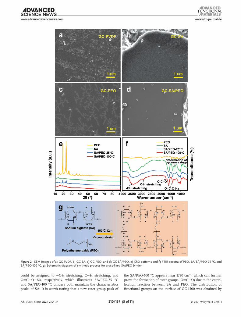
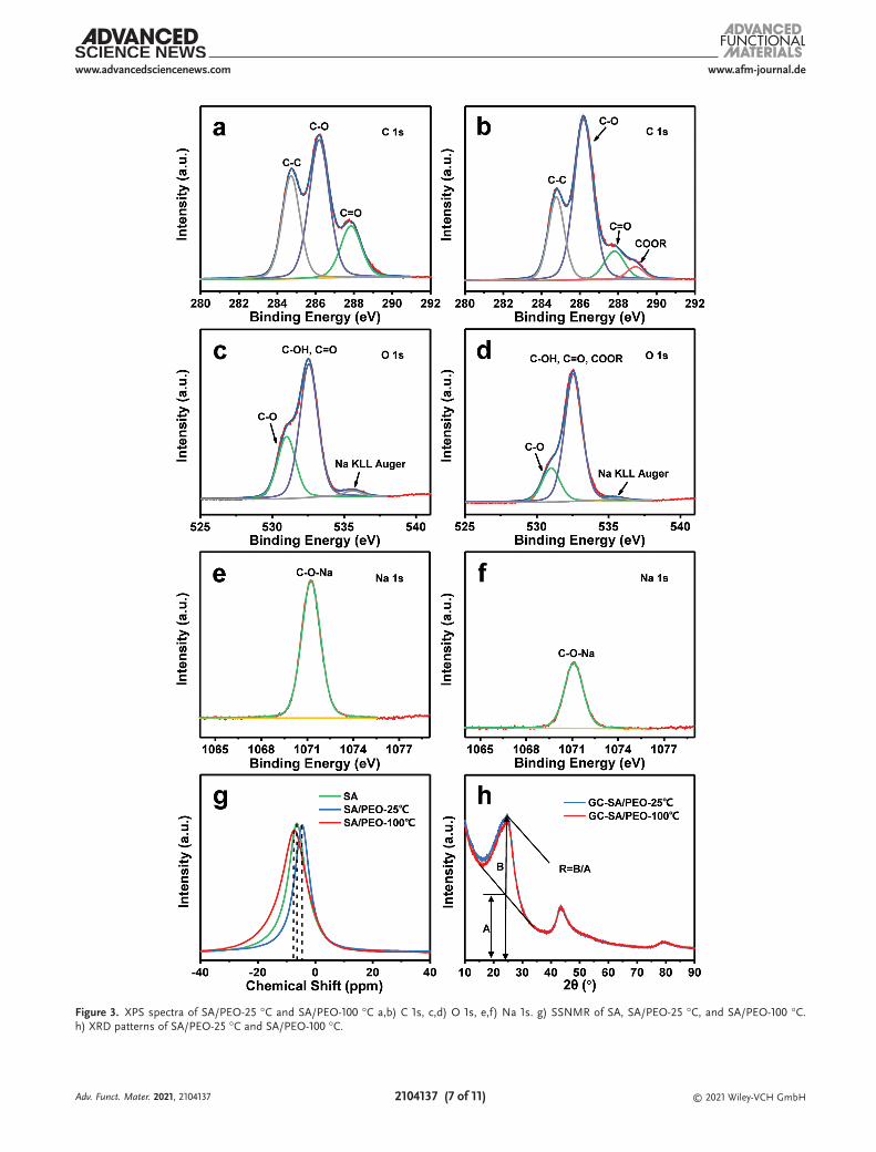
The changes of functional groups in SA/PEO-25 °C and SA/PEO-100 °C binders were analyzed by XPS. As shown in Figure S16, Supporting Information, the peak intensity of C 1s does not change much before and after the reaction, while the peak intensities of Na 1s and O 1s change dramatically. The C 1s spectrum showed that the SA/PEO-100 °C appeared as a new -COOR peak due to the esterification reaction of OH and COONa functional groups. In comparison, the SA/PEO-25 °C did not show a COOR peak, which was consistent with the results of FTIR (Figure 3a,b). The O 1s spectra showed that the intensities of Na KLL Auger peak and CO peak from SA/PEO-100 °C decreased after the reaction, indicating the decrease of CONa, which was also verified by Na 1s (Figure 3c–f). To explore the reason for the weakening of the CONa peak, the 23Na spectra of SA, SA/PEO-25 °C, and SA/PEO-100 °C were
analyzed by solid state nuclear magnetic resonance (SSNMR) to study for exploring the changes in the chemical environment of Na during the reaction process (Figure 3g). The generation of chemical shift is usually related to the change of the chemical environment. The 23Na spectra of SA, SA/PEO-25 °C, and SA/PEO-100 °C showed that the chemical shift first increased and then decreased, which proved that the chemical environment of Na+ changed during the reaction. Through combining with XPS analysis, the existing forms of Na mainly include NaOH gen-erated by hydrolysis and -COONa functional groups. Relevant studies show that PEO incorporates with lithium/sodium salts and lithium/sodium cations are solvated by the polymer chains, combining with the COC groups of PEO.[48,49] Therefore, sodium cations became movable through the chain movement, which provides abundant transport paths for ions, effectively improving the rate performance of the electrodes. In addition, the representative parameter (R) calculated by XRD patterns of GC-SA/PEO-25 °C and GC-SA/PEO-100 °C were examined to compare the degree of graphitization of materials. Based on the peak value of (002), the amorphous degree of carbon material is defined by R.[50] R represents the number of carbon plates arranged in a single layer along the c direction. The smaller the value of R is, the higher the carbon disorder and the lower the growth degree along the c direction. The R values of GC-SA/PEO-25 °C and GC-SA/PEO-100 °C are 2.19 and 2.15, respec-tively, indicating that the graphitization degree of GC-SA/PEO-100 °C reduces compared with GC-1500 (Figure 3h). AG/AD of GC-1500, GC-SA/PEO-25 °C, and GC-SA/PEO-100 °C are 0.654, 0.886, and 0.538, respectively, which also proves that the gra-phitization degree of GC-1500 is reduced during the esterifi-cation process of the SA/PEO binder (Figure S17, Supporting Information). It is speculated that Na+ is adsorbed on the defec-tive edges of the graphite microcrystallites of GC-1500. This effect can prefill Na+ in the irreversible defective sites, reducing the loss of irreversible capacity during the first charge– discharge process and improving the ICE of the GC-1500. Therefore, the design of the new SA/PEO binder can provide an additional Na+ source, which can not only bind to COC in PEO but also prefill irreversible defective sites to achieve a fast rate capability and a high ICE.
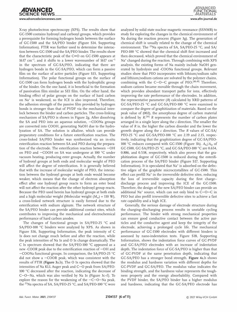
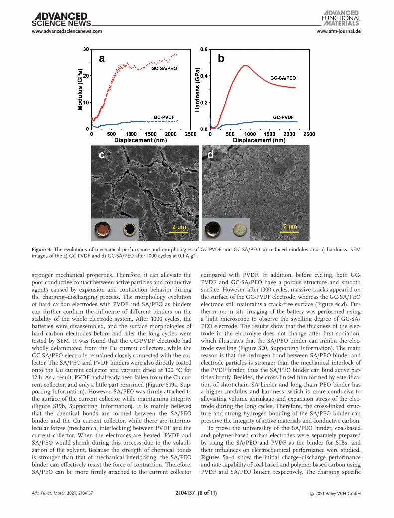
Generally, the serious damage of electrode structure during the charging–discharging process results in unstable cycling performance. The binder with strong mechanical properties can ensure good conductive contact between the active par-ticles and the conductive agent and keep the integrity of the electrode, achieving a prolonged cycle life. The mechanical performance of GC-1500 electrodes with different binders is assessed by nano-indentation tests. Figure S18, Supporting Information, shows the indentation force curves of GC-PVDF and GC-SA/PEO electrodes with an increase of indentation depth. The indentation force of GC-SA/PEO is higher than that of GC-PVDF at the same penetration depth, indicating that GC-SA/PEO has a stronger bond strength. Figure 4a,b shows the modulus and hardness variation with different depths for GC-PVDF and GC-SA/PEO. The modulus value indicates the binding strength, and the hardness value represents the tough-ness property and the energy absorbability. Compared with the PVDF binder, the SA/PEO binder has a higher modulus and hardness, indicating that the GC-SA/PEO electrode has
Adv. Funct. Mater. 2021, 2104137
www.afm-journal.dewww.advancedsciencenews.com
2104137 (7 of 11) © 2021 Wiley-VCH GmbH
Figure 3. XPS spectra of SA/PEO-25 °C and SA/PEO-100 °C a,b) C 1s, c,d) O 1s, e,f) Na 1s. g) SSNMR of SA, SA/PEO-25 °C, and SA/PEO-100 °C. h) XRD patterns of SA/PEO-25 °C and SA/PEO-100 °C.
Adv. Funct. Mater. 2021, 2104137
www.afm-journal.dewww.advancedsciencenews.com
2104137 (8 of 11) © 2021 Wiley-VCH GmbH
stronger mechanical properties. Therefore, it can alleviate the poor conductive contact between active particles and conductive agents caused by expansion and contraction behavior during the charging–discharging process. The morphology evolution of hard carbon electrodes with PVDF and SA/PEO as binders can further confirm the influence of different binders on the stability of the whole electrode system. After 1000 cycles, the batteries were disassembled, and the surface morphologies of hard carbon electrodes before and after the long cycles were tested by SEM. It was found that the GC-PVDF electrode had wholly delaminated from the Cu current collectors, while the GC-SA/PEO electrode remained closely connected with the col-lector. The SA/PEO and PVDF binders were also directly coated onto the Cu current collector and vacuum dried at 100 °C for 12 h. As a result, PVDF had already been fallen from the Cu cur-rent collector, and only a little part remained (Figure S19a, Sup-porting Information). However, SA/PEO was firmly attached to the surface of the current collector while maintaining integrity (Figure S19b, Supporting Information). It is mainly believed that the chemical bonds are formed between the SA/PEO binder and the Cu current collector, while there are intermo-lecular forces (mechanical interlocking) between PVDF and the current collector. When the electrodes are heated, PVDF and SA/PEO would shrink during this process due to the volatili-zation of the solvent. Because the strength of chemical bonds is stronger than that of mechanical interlocking, the SA/PEO binder can effectively resist the force of contraction. Therefore, SA/PEO can be more firmly attached to the current collector
compared with PVDF. In addition, before cycling, both GC-PVDF and GC-SA/PEO have a porous structure and smooth surface. However, after 1000 cycles, massive cracks appeared on the surface of the GC-PVDF electrode, whereas the GC-SA/PEO electrode still maintains a crack-free surface (Figure 4c,d). Fur-thermore, in situ imaging of the battery was performed using a light microscope to observe the swelling degree of GC-SA/PEO electrode. The results show that the thickness of the elec-trode in the electrolyte does not change after first sodiation, which illustrates that the SA/PEO binder can inhibit the elec-trode swelling (Figure S20, Supporting Information). The main reason is that the hydrogen bond between SA/PEO binder and electrode particles is stronger than the mechanical interlock of the PVDF binder, thus the SA/PEO binder can bind active par-ticles firmly. Besides, the cross-linked film formed by esterifica-tion of short-chain SA binder and long-chain PEO binder has a higher modulus and hardness, which is more conducive to alleviating volume shrinkage and expansion stress of the elec-trode during the long cycles. Therefore, the cross-linked struc-ture and strong hydrogen bonding of the SA/PEO binder can preserve the integrity of active materials and conductive carbon.
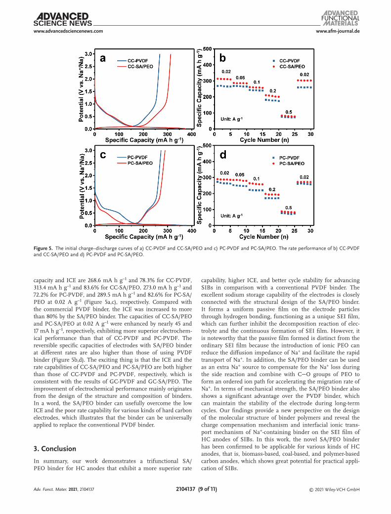
To prove the universality of the SA/PEO binder, coal-based and polymer-based carbon electrodes were separately prepared by using the SA/PEO and PVDF as the binder for SIBs, and their influences on electrochemical performance were studied. Figures 5a–d show the initial charge–discharge performance and rate capability of coal-based and polymer-based carbon using PVDF and SA/PEO binder, respectively. The charging specific
Figure 4. The evolutions of mechanical performance and morphologies of GC-PVDF and GC-SA/PEO: a) reduced modulus and b) hardness. SEM images of the c) GC-PVDF and d) GC-SA/PEO after 1000 cycles at 0.1 A g−1.
Adv. Funct. Mater. 2021, 2104137
www.afm-journal.dewww.advancedsciencenews.com
2104137 (9 of 11) © 2021 Wiley-VCH GmbH
capacity and ICE are 268.6 mA h g−1 and 78.3% for CC-PVDF, 313.4 mA h g−1 and 83.6% for CC-SA/PEO, 273.0 mA h g−1 and 72.2% for PC-PVDF, and 289.5 mA h g−1 and 82.6% for PC-SA/PEO at 0.02 A g−1 (Figure 5a,c), respectively. Compared with the commercial PVDF binder, the ICE was increased to more than 80% by the SA/PEO binder. The capacities of CC-SA/PEO and PC-SA/PEO at 0.02 A g−1 were enhanced by nearly 45 and 17 mA h g−1, respectively, exhibiting more superior electrochem-ical performance than that of CC-PVDF and PC-PVDF. The reversible specific capacities of electrodes with SA/PEO binder at different rates are also higher than those of using PVDF binder (Figure 5b,d). The exciting thing is that the ICE and the rate capabilities of CC-SA/PEO and PC-SA/PEO are both higher than those of CC-PVDF and PC-PVDF, respectively, which is consistent with the results of GC-PVDF and GC-SA/PEO. The improvement of electrochemical performance mainly originates from the design of the structure and composition of binders. In a word, the SA/PEO binder can usefully overcome the low ICE and the poor rate capability for various kinds of hard carbon electrodes, which illustrates that the binder can be universally applied to replace the conventional PVDF binder.
3. Conclusion
In summary, our work demonstrates a trifunctional SA/PEO binder for HC anodes that exhibit a more superior rate
capability, higher ICE, and better cycle stability for advancing SIBs in comparison with a conventional PVDF binder. The excellent sodium storage capability of the electrodes is closely connected with the structural design of the SA/PEO binder. It forms a uniform passive film on the electrode particles through hydrogen bonding, functioning as a unique SEI film, which can further inhibit the decomposition reaction of elec-trolyte and the continuous formation of SEI film. However, it is noteworthy that the passive film formed is distinct from the ordinary SEI film because the introduction of ionic PEO can reduce the diffusion impedance of Na+ and facilitate the rapid transport of Na+. In addition, the SA/PEO binder can be used as an extra Na+ source to compensate for the Na+ loss during the side reaction and combine with CO groups of PEO to form an ordered ion path for accelerating the migration rate of Na+. In terms of mechanical strength, the SA/PEO binder also shows a significant advantage over the PVDF binder, which can maintain the stability of the electrode during long-term cycles. Our findings provide a new perspective on the design of the molecular structure of binder polymers and reveal the charge compensation mechanism and interfacial ionic trans-port mechanism of Na+-containing binder on the SEI film of HC anodes of SIBs. In this work, the novel SA/PEO binder has been confirmed to be applicable for various kinds of HC anodes, that is, biomass-based, coal-based, and polymer-based carbon anodes, which shows great potential for practical appli-cation of SIBs.
Figure 5. The initial charge–discharge curves of a) CC-PVDF and CC-SA/PEO and c) PC-PVDF and PC-SA/PEO. The rate performance of b) CC-PVDF and CC-SA/PEO and d) PC-PVDF and PC-SA/PEO.
Adv. Funct. Mater. 2021, 2104137
www.afm-journal.dewww.advancedsciencenews.com
2104137 (10 of 11) © 2021 Wiley-VCH GmbH
4. Experimental SectionPreparation of Binders: 3 wt% SA/PEO binder was prepared by dissolving
the SA (Mw = 198.11, Aladdin) and PEO (Mw = 110W, Canrd) in an aqueous solution with a mass ratio of 9:1. SA, PEO, and PVDF (Arkema) were dissolved in an aqueous solution to prepare 5 wt% SA, PEO, and PVDF binders, respectively. Then, these binders were continuously stirred for 12 h. Moreover, SA/PEO binders were dried at 25 and 100 °C for 12 h, respectively, named as SA/PEO-25 °C and SA/PEO-100 °C.
Preparation of Hard Carbon Samples: GC was synthesized to test the electrochemical performance of different binders for sodium storage. Typically, the glucose was carbonized at 1400, 1500, and 1600 °C for 2 h in argon atmosphere, respectively, which are denoted as GC-1400, GC-1500, and GC-1600. In order to verify the universality of synthetic binders, two commonly used hard carbons (Xinjiang coal-based carbon and resin polymer-based carbon) were selected to further test the performance of sodium storage. Xinjiang coal and resin polymer were synthesized based on the previous study, respectively.[51,52] Specifically, resin polymer was prepared without Ludox added. Finally, Xinjiang coal carbonized at 1400 °C and resin polymer carbonized at 1600 °C for 2 h in argon atmosphere were denoted as CC-1400 and PC-1600, respectively.
Preparation of Hard Carbon Anodes: 80 wt% GC-1500, 10 wt% carbon nanotubes, and 10 wt% binders (PVDF, SA, PEO, or SA/PEO) were blended to form a series of slurry mixtures, which were coated onto copper foil and dried at 100 °C under vacuum for 24 h, respectively. Subsequently, each electrode film was cut into 12 mm-discs. The working electrodes were named as GC-PVDF, GC-SA, GC-PEO, and GC-SA/PEO, respectively. Xinjiang coal- and resin polymer-based carbon electrodes were prepared by the same method using active materials (CC-1400 and PC-1600), carbon nanotubes, and binders (PVDF and SA/PEO), which were named as CC-PVDF, CC-SA/PEO, PC-PVDF, and PC-SA/PEO, respectively. The mass loading of active materials is around 1.2 mg cm−2.
Material Characterization: The morphology, microstructure, and element distribution of samples were observed by SEM (Hitachi SU8220) and TEM (FEI Tecnai G2 F30) instruments. XRD patterns were characterized by a PANalytical X’Pert powder diffractometer using Cu Kα radiation (λ = 0.15418 nm). FTIR (Nicolet 6700), and XPS (ESCALAB XI+) were used for elemental analysis and speculation on chemical bonding information. The surface areas were measured by nitrogen adsorption–desorption apparatus (ASAP 3000, Micromeritics, USA) and estimated by the BET method. Raman spectrum was examined by a Raman spectrometer (DXR Smart Raman) with a 532 nm laser excitation. The MAS NMR 23Na spectra were obtained by the SSNMR (Agilent DD2-500MHz, USA). The nanoindentation tests were performed on the Nano Indenter (100BA-1C, MTS, USA). A constant load of 1 mn was applied during the test.
Electrochemical Tests: CR2025 coin cells were assembled in a glove box and 1 m NaPF6 in ethylene carbonate (EC)/dimethyl carbonate (DMC) (1:1 v/v) was used as the electrolyte. Glass fiber (Whatman) was taken as a separator, and a 12 mm homemade sodium disk acted as a counter electrode. CV measurement was measured at 0.1 mV s−1 between 0.01 and 2.00 V versus Na+/Na on a CHI 600E electrochemical workstation (CH Instruments Inc., China). The charge–discharge curves were collected by a battery testing system (LANHE CT2001A, China) between 0.01 and 3.00 V versus Na+/Na at different current densities.
Supporting InformationSupporting Information is available from the Wiley Online Library or from the author.
AcknowledgementsThis work was supported by the National Science Fund for the National Natural Science Foundation of China (No.21776041 and No.21875028) and Liao Ning Revitalization Talents Program (XLYC1902045).
Conflict of InterestThe authors declare no conflict of interest.
Data Availability StatementThe data that supports the findings of this study are available in the supplementary material of this article.
Keywordshard carbon, initial Coulombic efficiency, rate capability, sodium-ion batteries, trifunctional binder
Received: May 1, 2021Revised: June 4, 2021
Published online:
[1] Y. Yang, W.-F. Wei, Rare Met. 2020, 39, 332.[2] Z. Li, C. Zhang, F. Han, F. Wang, F. Zhang, W. Shen, C. Ye, X. Li,
J. Liu, J. Mater. Chem. A 2020, 8, 2430.[3] Z. Li, C. Zhang, F. Han, F. Zhang, D. Zhou, S. Xu, H. Liu, X. Li,
J. Liu, Nano Res. 2019, 12, 1836.[4] J. Qian, F. Wu, Y. Ye, M. Zhang, Y. Huang, Y. Xing, W. Qu, L. Li,
R. Chen, Adv. Energy Mater. 2018, 8, 1703159.[5] D. Luo, J. Xu, Q. B. Guo, L. Z. Fang, X. H. Zhu, Q. Y. Xia, H. Xia,
Adv. Funct. Mater. 2018, 28, 1805371.[6] Z. Siwei, Z. Jun, W. Sida, L. Wei, K. Feiyu, Y. Quan-Hong, Acta Chim.
Sin. 2017, 75, 163.[7] B. Cao, X. Li, Acta Phys.-Chim. Sin. 2020, 36, 1905003.[8] H. Chen, M. Ling, L. Hencz, H. Y. Ling, G. Li, Z. Lin, G. Liu,
S. Zhang, Chem. Rev. 2018, 118, 8936.[9] J.-T. Li, Z.-Y. Wu, Y.-Q. Lu, Y. Zhou, Q.-S. Huang, L. Huang,
S.-G. Sun, Adv. Energy Mater. 2017, 7, 1701185.[10] D. Ni, W. Sun, C. Lu, Z. Wang, J. Qiao, H. Cai, C. Liu, K. Sun,
J. Power Sources 2019, 413, 449.[11] D. Kim, C. Hwang, J. Jeong, W.-J. Song, S. Park, H.-K. Song, ACS
Appl. Mater. Interfaces 2019, 11, 43039.[12] V. M. Nagulapati, D. S. Kim, J. Oh, J. H. Lee, J. Hur, I. T. Kim,
S. G. Lee, Nanomaterials 2019, 9, 1134.[13] V. M. Nagulapati, Y. H. Yoon, D. S. Kim, H. Kim, W. S. Lee, J. H. Lee,
K. H. Kim, J. Hur, I. T. Kim, S. G. Lee, J. Ind. Eng. Chem. 2019, 76, 419.[14] L. Xiao, H. Lu, Y. Fang, M. L. Sushko, Y. Cao, X. Ai, H. Yang, J. Liu,
Adv. Energy Mater. 2018, 8, 1703238.[15] H. Huang, R. Xu, Y. Feng, S. Zeng, Y. Jiang, H. Wang, W. Luo, Y. Yu,
Adv. Mater. 2020, 32, 1904320.[16] J. Peters, D. Buchholz, S. Passerini, M. Weil, Energy Environ. Sci.
2016, 9, 1744.[17] F. Xie, Z. Xu, A. C. S. Jensen, F. Ding, H. Au, J. Feng, H. Luo,
M. Qiao, Z. Guo, Y. Lu, A. J. Drew, Y.-S. Hu, M.-M. Titirici, J. Mater. Chem. A 2019, 7, 27567.
[18] Y. Li, Y. Lu, Q. Meng, A. C. S. Jensen, Q. Zhang, Y. Tong, Y. Qi, L. Gu, M.-M. Titirici, Y.-S. Hu, Adv. Energy Mater. 2019, 9, 1902852.
[19] E. Olsson, J. Cottom, H. Au, Z. Guo, A. C. S. Jensen, H. Alptekin, A. J. Drew, M.-M. Titirici, Q. Cai, Adv. Funct. Mater. 2020, 30, 1908209.
[20] P. Lu, Y. Sun, H. Xiang, X. Liang, Y. Yu, Adv. Energy Mater. 2018, 8, 1702434.
[21] M. Yu, Z. Yin, G. Yan, Z. Wang, H. Guo, G. Li, Y. Liu, L. Li, J. Wang, J. Power Sources 2020, 449, 227514.
Adv. Funct. Mater. 2021, 2104137
www.afm-journal.dewww.advancedsciencenews.com
2104137 (11 of 11) © 2021 Wiley-VCH GmbH
[22] Q. Jin, W. Li, K. Wang, H. Li, P. Feng, Z. Zhang, W. Wang, K. Jiang, Adv. Funct. Mater. 2020, 30, 1909907.
[23] F. Xie, Z. Xu, A. C. S. Jensen, H. Au, Y. Lu, V. Araullo-Peters, A. J. Drew, Y.-S. Hu, M.-M. Titirici, Adv. Funct. Mater. 2019, 29, 1901072.
[24] M. Liu, J. Zhang, S. Guo, B. Wang, Y. Shen, X. Ai, H. Yang, J. Qian, ACS Appl. Mater. Interfaces 2020, 12, 17620.
[25] J. Zhang, D.-W. Wang, W. Lv, L. Qin, S. Niu, S. Zhang, T. Cao, F. Kang, Q.-H. Yang, Adv. Energy Mater. 2018, 8, 1801361.
[26] J. Zhang, D.-W. Wang, W. Lv, S. Zhang, Q. Liang, D. Zheng, F. Kang, Q.-H. Yang, Energy Environ. Sci. 2017, 10, 370.
[27] L. A. Ma, A. J. Naylor, L. Nyholm, R. Younesi, Angew. Chem. Int. Ed. 2021, 60, 4855; Angew. Chem. 2021, 133, 4905.
[28] H. Lu, X. Chen, Y. Jia, H. Chen, Y. Wang, X. Ai, H. Yang, Y. Cao, Nano Energy 2019, 64, 103903.
[29] Z. Li, Y. Zhang, T. Liu, X. Gao, S. Li, M. Ling, C. Liang, J. Zheng, Z. Lin, Adv. Energy Mater. 2020, 10, 1903110.
[30] S. Sun, D. He, P. Li, Y. Liu, Q. Wan, Q. Tan, Z. Liu, F. An, G. Gong, X. Qu, J. Power Sources 2020, 454, 227907.
[31] I. Kovalenko, B. Zdyrko, A. Magasinski, B. Hertzberg, Z. Milicev, R. Burtovyy, I. Luzinov, G. Yushin, Science 2011, 334, 75.
[32] J. Liu, Q. Zhang, Z.-Y. Wu, J.-H. Wu, J.-T. Li, L. Huang, S.-G. Sun, Chem. Commun. 2014, 50, 6386.
[33] Z.-Y. Gu, Z.-H. Sun, J.-Z. Guo, X.-X. Zhao, C.-D. Zhao, S.-F. Li, X.-T. Wang, W.-H. Li, Y.-L. Heng, X.-L. Wu, ACS Appl. Mater. Interfaces 2020, 12, 47580.
[34] M.-H. Ryou, J. Kim, I. Lee, S. Kim, Y. K. Jeong, S. Hong, J. H. Ryu, T.-S. Kim, J.-K. Park, H. Lee, J. W. Choi, Adv. Mater. 2013, 25, 1571.
[35] Y. Liu, Z. Tai, T. Zhou, V. Sencadas, J. Zhang, L. Zhang, K. Konstantinov, Z. Guo, H. K. Liu, Adv. Mater. 2017, 29, 1703028.
[36] L. Yue, L. Zhang, H. Zhong, J. Power Sources 2014, 247, 327.
[37] C. Chen, S. H. Lee, M. Cho, J. Kim, Y. Lee, ACS Appl. Mater. Interfaces 2016, 8, 2658.
[38] M. Ling, Y. Xu, H. Zhao, X. Gu, J. Qiu, S. Li, M. Wu, X. Song, C. Yan, G. Liu, S. Zhang, Nano Energy 2015, 12, 178.
[39] J. Liu, Q. Zhang, T. Zhang, J.-T. Li, L. Huang, S.-G. Sun, Adv. Funct. Mater. 2015, 25, 3599.
[40] S. S. Zhang, T. R. Jow, J. Power Sources 2002, 109, 422.[41] H. Liu, T. Chen, Z. Xu, Z. Liu, J. Yang, J. Chen, ACS Appl. Mater.
Interfaces 2020, 12, 54842.[42] S. Wu, Y. Yang, C. Liu, T. Liu, Y. Zhang, B. Zhang, D. Luo, F. Pan,
Z. Lin, ACS Energy Lett. 2021, 6, 290.[43] T. Zhang, J.-t. Li, J. Liu, Y.-p. Deng, Z.-g. Wu, D. Guo, L. Huang,
S.-G. Sun, Chem. Commun. 2016, 52, 4683.[44] S. S. Zhang, J. Electrochem. Soc. 2012, 159, A1226.[45] D. Guy, B. Lestriez, R. Bouchet, V. Gaudefroy, D. Guyomard,
Electrochem. Solid-State Lett. 2005, 8, A17.[46] D. Guy, B. Lestriez, R. Bouchet, D. Guyomard, J. Electrochem. Soc.
2006, 153, A679.[47] J. Yang, P. Li, F. Zhong, X. Feng, W. Chen, X. Ai, H. Yang, D. Xia,
Y. Cao, Adv. Energy Mater. 2020, 10, 1904264.[48] W. Zeng, L. Wang, X. Peng, T. Liu, Y. Jiang, F. Qin, L. Hu, P. K. Chu,
K. Huo, Y. Zhou, Adv. Energy Mater. 2018, 8, 1702314.[49] C. Sun, J. Liu, Y. Gong, D. P. Wilkinson, J. Zhang, Nano Energy 2017,
33, 363.[50] Y. Qi, Y. Lu, F. Ding, Q. Zhang, H. Li, X. Huang, L. Chen, Y.-S. Hu,
Angew. Chem. 2019, 131, 4405.[51] B.-Y. Wang, J.-L. Xia, X.-L. Dong, X.-S. Wu, L.-J. Jin, W.-C. Li, Energy
Fuel 2020, 34, 16831.[52] S. Wang, L. Zhang, F. Han, W.-C. Li, Y.-Y. Xu, W.-H. Qu, A.-H. Lu,
ACS Appl. Mater. Interfaces 2014, 6, 11101.
Adv. Funct. Mater. 2021, 2104137