RATED CAPACITY MANUAL MODEL AT-20
25
ABN : 86 010 671 048 ACN : 010 671 048 E-Mail : [email protected] Internet : www.terex.com.au Terex Lifting Australia Pty. Ltd. 16C1320-/0-1 Revision B – 24 August 2005 RATED CAPACITY MANUAL MODEL AT-20 BOOK PART NUMBER 16C1320- HYDRAULIC ALL TERRAIN PICK & CARRY CRANE 20 TONNE MAXIMUM CAPACITY Do not operate this crane unless you have read and understood the information in this book.
Transcript of RATED CAPACITY MANUAL MODEL AT-20

ABN : 86 010 671 048ACN : 010 671 048E-Mail : [email protected] : www.terex.com.au
Terex Lifting Australia Pty. Ltd.
16C1320-/0-1Revision B – 24 August 2005
RATED CAPACITY MANUAL
MODEL AT-20BOOK PART NUMBER 16C1320-
HYDRAULIC ALL TERRAIN PICK& CARRY CRANE
20 TONNE MAXIMUM CAPACITY
Do not operate thiscrane unless you haveread and understood
the information in thisbook.

16C1320-/0-2Revision B – 24 August 2005
16C1320-RATED CAPACITY MANUALAT-20
ALL PAGES LISTED MUST BE INCLUDED IN THIS BOOK.
Page No. Description
RATED CAPACITY MANUAL MODEL AT-20
0-1 MODEL NUMBER INDEX0-2 PAGE LIST
SECTION 1 – WARNINGS
1-1 INDEX, SECTION 11-2 CAUTION1-3 DEFINITIONS1-4 WARNINGS, PAGE 11-5 WARNINGS, PAGE 21-6 WARNINGS, PAGE 31-7 OPERATION ON SIDE SLOPES1-8 SIDE SLOPE DERATION CHART
SECTION 2 – OPERATION
2-1 INDEX, SECTION 22-2 RANGE DIAGRAM & WORKING AREA DIAGRAM2-3 ATTACHMENT MASSES, HOOK BLOCK RC, TYRE SPECIFICATIONS &
TYRE INFLATION CHART
SECTION 3 – LIFTING CAPACITY
3-1 LMI CODES3-2 RANGE DIAGRAM3-3 LMI DUTY 01 : WINCH - POWERED SECTIONS3-4 LMI DUTY 03 : WINCH – MANUAL EXTENSION3-5 LMI DUTY 02 : RHINO HOOK - POWERED SECTIONS3-6 LMI DUTY 04 : RHINO HOOK – MANUAL EXTENSION3-7 LMI DUTY 05 & 6 : FLYJIB (0° OFFSET)3-8 LMI DUTY 07 & 8 : FLYJIB (12.5° OFFSET)3-9 LMI DUTY 09 : FIXED LUG ON BUTT3-10 LMI DUTY 10 : INNER LUG ON FIRST EXT.3-11 LMI DUTY 11 : OUTER LUG ON FIRST EXT.3-12 LMI DUTY 12 & 13 : MAN BASKET

16C1320-/1-1Revision A – 24 August 2005
SECTION 1
WARNINGS
CAUTION NOTE
ATTACHMENT NOTICE
DEFINITIONS
WARNINGS
OPERATION ON SIDE SLOPES

16C1320-/1-2Revision A – 24 August 2005
! CAUTION ! .IMPROPER CRANE USE, CARE OR OPERATION CAN
CAUSE INJURY, DEATH OR PROPERTY DAMAGE.
DO NOT OPERATE THIS MACHINE UNLESS YOU HAVEREAD AND UNDERSTAND THE OPERATOR’S MANUAL
AND CRANE RATED CAPACITY MANUAL.
COPIES OF OPERATOR’S MANUALS AND CRANE RATED CAPACITY MANUALMAY BE OBTAINED FROM:
NOTICE .WRITTEN AUTHORISATION IS REQUIRED FROM TEREX
LIFTING AUSTRALIA PTY LTD PRIOR TO THE USE OFANY ATTACHMENT NOT SPECIFIED IN THE MANUAL.
16C1320-/1-3Revision A – 24 August 2005
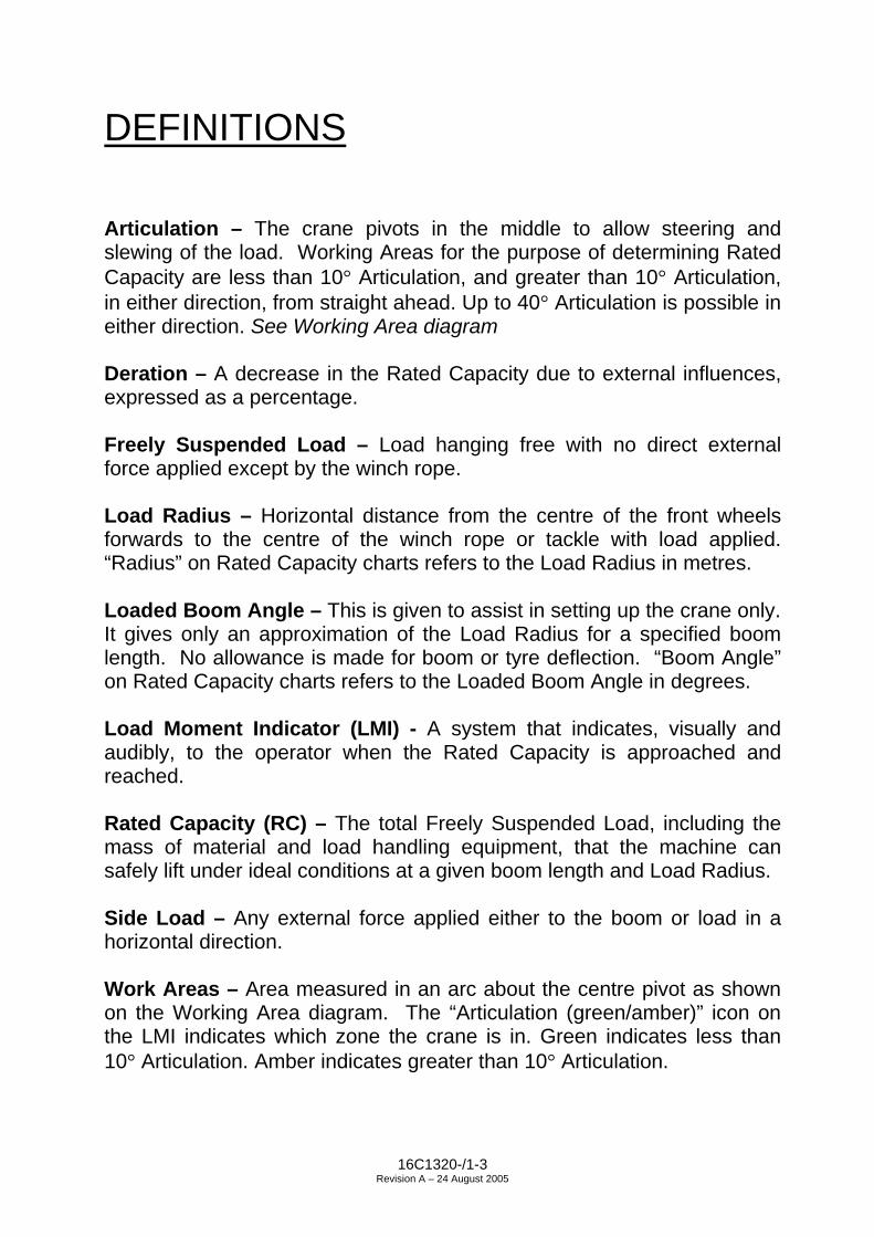
DEFINITIONS
Articulation – The crane pivots in the middle to allow steering andslewing of the load. Working Areas for the purpose of determining RatedCapacity are less than 10° Articulation, and greater than 10° Articulation,in either direction, from straight ahead. Up to 40° Articulation is possible ineither direction. See Working Area diagram
Deration – A decrease in the Rated Capacity due to external influences,expressed as a percentage.
Freely Suspended Load – Load hanging free with no direct externalforce applied except by the winch rope.
Load Radius – Horizontal distance from the centre of the front wheelsforwards to the centre of the winch rope or tackle with load applied.“Radius” on Rated Capacity charts refers to the Load Radius in metres.
Loaded Boom Angle – This is given to assist in setting up the crane only.It gives only an approximation of the Load Radius for a specified boomlength. No allowance is made for boom or tyre deflection. “Boom Angle”on Rated Capacity charts refers to the Loaded Boom Angle in degrees.
Load Moment Indicator (LMI) - A system that indicates, visually andaudibly, to the operator when the Rated Capacity is approached andreached.
Rated Capacity (RC) – The total Freely Suspended Load, including themass of material and load handling equipment, that the machine cansafely lift under ideal conditions at a given boom length and Load Radius.
Side Load – Any external force applied either to the boom or load in ahorizontal direction.
Work Areas – Area measured in an arc about the centre pivot as shownon the Working Area diagram. The “Articulation (green/amber)” icon onthe LMI indicates which zone the crane is in. Green indicates less than10° Articulation. Amber indicates greater than 10° Articulation.

16C1320-/1-4Revision A – 24 August 2005
! WARNING ! .SPECIAL PRECAUTIONS FOR ARTICULATED CRANES
THERE IS A POTENTIAL FOR CRUSHING BETWEEN FRONT AND REARCHASSIS WHEN THE MACHINE ARTICULATES. NEVER STAND IN THE PIVOTAREA WHEN THE ENGINE IS RUNNING OR EMERGENCY STEERING PUMP ISOPERATING. ALWAYS REMOVE THE KEY FROM THE IGNITION BEFOREWORKING IN THE PIVOT AREA.DO NOT LEAVE IGNITION KEY SWITCHED ON WITH ENGINE STOPPED ANDPARK BRAKE OFF, AS EMERGENCY HYDRAULIC STEERING PUMP WILLACTIVATE.
GENERAL1. This machine has been designed to meet the requirements of AS1418.1 &
1418.5 and has been tested in accordance with these standards for pick andcarry operation on tyres.
2. Rated Capacities shown are for this machine as originally manufactured byTerex Lifting Australia Pty Ltd. The Rated Capacities only apply when all theinstructions in this book are rigidly followed. Modifications to this machine oruse of equipment other than that specified can result in a reduction in RatedCapacity.
3. If improperly operated or maintained, this machine can be hazardous.Operation and maintenance of this machine must be in compliance with theinformation documented in the operators, service and parts manuals furnished.If these manuals are missing, obtain replacements throughTerex Lifting Australia Pty Ltd or their agents.
SET-UP4. Reduced crane Rated Capacities for the particular job shall be established, by
the operator, with due allowance for adverse operating conditions. Theseconditions include the supporting surface, pendulum action of the load, jerkingor sudden stops of the load and other factors affecting stability, two machinelifts, electrical wires, adverse weather, wind, hazardous surroundings,experience of personnel, etc.
5. Rated Capacity is based on Freely Suspended Loads with the machine on afirm, level (max. 1% slope / 0.6°) and uniform surface. Lifting, or travelling witha load, on soft or uneven ground can be hazardous and will reduce the RatedCapacity of the crane. Refer to the “OPERATION ON SIDE SLOPES” in thismanual. No attempt shall be made to drag the load along the ground in anydirection.
6. Wind forces on the boom, resulting from winds up to 10 m/s (36 km/h), areincorporated in the Rated Capacity. Any additional Side Loading due to windforces on the load will reduce the Rated Capacity, and must be considered.

16C1320-/1-5Revision A – 24 August 2005
! WARNING ! .7. Rated Capacities above the red line are based on the machine’s hydraulic or
structural competence and not on machine stability. Rated Capacities belowthe red line are based on machine stability.
8. Rated Capacities include the mass of hooks, blocks, slings and auxiliary liftingdevices. Their mass must be subtracted, from the listed Rated Capacity, todetermine the equivalent net load.
9. Loaded Boom Angles at specified boom lengths give only an approximation ofthe Load Radius. The Boom Angle before loading should be greater to accountfor boom deflection increasing the Load Radius as the load is lifted.
OPERATION10. Read and understand all warnings and instructional notes.11. Do not tip the machine to determine allowable lifting capacities.12. Loads may be lifted from the main boom head on the winch, the rhino hook, the
fixed lug, or either of the two sliding lugs on the boom. A flyjib is also availableto extend the maximum boom length and a manbasket can be pinned to thehead of the boom. Always use the correct Rated Capacity chart for the liftingpoint in use and ensure the LMI is set to the correct duty. Written authorisationfrom Terex Lifting Australia Pty Ltd is required prior to the use of anyattachment not specified in the manual.
13. Lifting from more than one lifting point simultaneously is neither intended norapproved.
14. Handling of personnel from the boom is neither intended nor approved, exceptin a Terex Lifting Australia supplied manbasket, correctly installed on the headof the boom, or other approved arrangement.
15. When either the boom length or Load Radius or both are between values listed,the smallest load shown at either the next larger Load Radius or boom lengthshall be used, or the interpolated value shown on the LMI may be used.
16. Side Loading of the machine and load swing out may cause structural failure ormachine tip-over. Side Loads may be generated by: lifting when not level;sudden acceleration or deceleration in Articulating with a load; dragging a load;pushing a load; wind forces on load and boom structure.
17. Rated Capacity of the manual extension is determined by Loaded Boom Angle.The boom may be retracted and extended with the manual set, however, theRated Capacity does not change from the fully extended position for the givenLoaded Boom Angle.
18. It is safe to attempt to telescope any load within the limits of the Rated CapacityManual. The maximum load that may be telescoped is limited by hydraulicpressure, Loaded Boom Angle and powered boom sections lubrication.

16C1320-/1-6Revision A – 24 August 2005
! WARNING ! . 19. The winch rope is fully compensated for boom extension. The only exception is
when the manual extension is being set. Refer to the operator’s manual for themanual setting procedure. Once it is set the compensation is fully functional.
20. Do not allow the winch rope to unwind fully. Always ensure a minimum of2 wraps of rope remain on the winch drum. Note the areas on the rangediagram where the fall block cannot reach the ground on 4 or 3 parts of rope.
21. Rated Capacity depends on tyre rating, tyre condition and tyre inflationpressure. All tyres must be in good condition and must be inflated to therecommended pressure before attempting a lift.
22. Pick & carry operation is permitted through the full Articulation range, however,Rated Capacity is reduced above 10° Articulation. Use the reduced capacitiesin the chart if entering this Articulation zone during the operation.
23. The maximum speed for pick & carry operation is 0.4m/s (1.44km/h). Thetransfer case shall be set to low range.
24. Operation of this crane in excess of the Rated Capacity and disregard of theinstructions is hazardous.

16C1320-/1-7Revision A – 24 August 2005
OPERATION ON SIDE SLOPES
Mobile Cranes are primarily designed to be used on firm, flat, level ground (to within1% gradient), according to AS 1418.5, any deviation from this requires that theRated Capacity shall be reduced accordingly. As per AS 2550.5 – negotiation ofslopes by mobile cranes travelling with Freely Suspended Loads should be avoided.The following precautions should be taken when operating on side slopes of up to 5°(8.75% gradient) – REMEMBER surface depressions and potholes will create thesame effect as a side slope.
• Ensure the tyres are correctly INFLATED as per the rated capacity manual.
• Ensure the ground condition is FIRM enough to support the axle loads.
• REDUCE the Rated Capacity of the crane by the percentage value for the crane asshown in figure 1 for operating on side slopes up to 5° (8.75% gradient) -REMEMBER the crane’s load indicator will NOT automatically derate the RatedCapacity.
• Use the crane’s side slope inclinometer as a guide only, it is most accurate whenthe crane’s Articulation is straight ahead without suspending a load. All Articulatedchassis cranes will show some degree of side tilt, when Articulated with a load –this should not be confused with the ground’s side slope.
• Use the MINIMUM boom length and Loaded Boom Angle practical to keep theboom tip as close to the ground as possible.
• Keep the load as CLOSE to the ground as possible.
• Use the MINIMUM Articulation angle practical - REMEMBER the crane will side tiltand hence the hook will move towards the direction of Articulation whilst steering.
• Keep the load on the UPHILL side of the crane where possible, especially whenArticulated – REMEMBER the working Load Radius will increase if the load issuspended in the downhill position.
• Load swing greatly reduces stability – REMEMBER to tagline loads to preventpendulum motion of the load. Travel and crane motions should be applied gentlyto minimise this effect.

16C1320-/1-8Revision A – 24 August 2005
Figure 1: Percentage Deration Chart for AT-20 at 5° Side Slope
Note:1. Percentage deration chart is based on 66.6% stability as per AS 1418.5 with the crane on a firm
side slope of 5° (8.75% Gradient).2. The percentage deration is dependent upon the location of the lifting point on the boom.3. The percentage deration should be applied to the Rated Capacity as read off the Rated Capacity
Manual for the applicable boom length, Loaded Boom Angle, Load Radius and Articulation angle.
Example (For AT-20 Crane, Rated Capacity Manual 16C1320-):
Lifting condition: Boom Length: 11.0 m
Loaded Boom Angle: 34.0°Load Radius: 7.0 m
Articulation Angle: Greater than 10°
RC (Level ground): 3750 kg (From Rated Capacity Manual LMI Duty 01, for abovelifting conditions)
Percentage Deration: 40 % (From Figure 1: Percentage Deration Chart)
RC (5° Slide Slope) = RC (as per Rated Capacity Manual) – Percentage Derationx RC (as per Rated Capacity Manual) / 100 %
= 3750 kg – 40% x 3750 kg / 100% = 2250 kg

16C1320-/2-1Revision C - 24 August 2005
SECTION 2
OPERATIONS
RANGE DIAGRAM AT-20
WORKING AREA DIAGRAM
ATTACHMENT MASSES
HOOK BLOCK RC
TYRE SPECIFICATIONS
TYRE INFLATION CHART

16C1320-/2-2Revision C - 24 August 2005
RANGE DIAGRAM AT-20SHOWINGALL LIFTINGCONFIGURATIONS
WORKING AREA DIAGRAM

16C1320-/2-3Revision C - 24 August 2005
ATTACHMENT MASSES
SINGLE PART HOOK BLOCK PL16M2090 30 kgTWO/THREE PART HOOK BLOCK PL16A3010 95 kgFOUR PART HOOK BLOCK PL16A3058 125 kgFOUR PART HOOK BLOCK PL16A3074 180 kg20 METRIC TONNE HOOK PP2190100 15 kg12 METRIC TONNE SPREADER BAR PL16A3035 110 kg
NOTE : THESE MASSES APPLY ONLY TO TEREX LIFTINGAUSTRALIA PTY LTD SUPPLIED EQUIPMENT.
HOOK BLOCK RCNumber of Parts
of RopePermissible Winch
Load (kg)1 4 200
2 8 400
3 12 600
4 16 800
Wire Rope : 14mm 35W x 7 Non-rotating Compak Minimum Breaking Force 165 kN
1 Speed Winch - 65m2 Speed Winch - 100m
TYRE SPECIFICATIONS
Condition Speed Load Rating
Pick & Carry <1.44 km/h 8680 kg per tyre at 120psi(dual fitment)
Highway 90 km/h 3000 kg per tyre at 100psi(dual fitment)
TYRE INFLATION CHARTInflation Pressure – psiPosition Construction
Pick & Carry Highway TravelFront 12.00 x 20 120 120Rear 12.00 x 20 100 100

16C1320-/3-1
SECTION 3
LIFTING CAPACITYRANGE DIAGRAM (ALL LIFTS)
LMI DUTY 01 : LIFTING CAPACITY ON WINCH -POWERED SECTIONS
LMI DUTY 03 : LIFTING CAPACITY ON WINCH –MANUAL EXTENSION
LMI DUTY 02 : LIFTING CAPACITY ON RHINO HOOK -POWEREDSECTIONS
LMI DUTY 04 : LIFTING CAPACITY ON RHINO HOOK –MANUAL EXTENSION
LMI DUTY 05 : LIFTING CAPACITY ON FLYJIB(0° OFFSET) - POWERED SECTIONS
LMI DUTY 06 : LIFTING CAPACITY ON FLYJIB(0° OFFSET) - MANUAL EXTENSION
LMI DUTY 07 : LIFTING CAPACITY ON FLYJIB(12.5° OFFSET) - POWERED SECTIONS
LMI DUTY 08 : LIFTING CAPACITY ON FLYJIB (12.5° OFFSET) - MANUAL EXTENSION
LMI DUTY 09 : LIFTING CAPACITY ON FIXED LUG ON BUTT
LMI DUTY 10 : LIFTING CAPACITY ON INNER LUG ON FIRST EXT.
LMI DUTY 11 : LIFTING CAPACITY ON OUTER LUG ON FIRST EXT.
LMI DUTY 12 : LIFTING CAPACITY IN MAN BASKET –POWERED SECTIONS
LMI DUTY 13 : LIFTING CAPACITY IN MAN BASKET – MANUAL EXTENSION

16C1320-/3-2Revision A - 24 August 2005
RANGE DIAGRAM AT-20SHOWING ALL LIFT CONFIGURATIONS

BO
OM
LE
NG
TH
(m
)R
AD
IUS
5.67
6.00
6.50
7.00
7.50
8.00
8.50
9.00
9.50
10.0
010
.50
11.0
011
.50
12.0
012
.50
13.0
013
.50
13.8
516
800
1625
015
450
1490
01.
612
600
1260
012
600
1260
048
5154
5716
800
1680
016
500
1570
015
100
1470
014
350
2.0
1260
012
600
1260
012
600
1260
012
600
1260
042
4650
5356
5860
1390
013
900
1390
013
850
1385
013
850
1385
013
200
1300
02.
512
150
1215
012
100
1210
012
100
1210
012
100
1205
012
050
3439
4448
5154
5658
6011
450
1145
011
450
1140
011
400
1140
011
400
1140
011
400
1115
010
250
3.0
9950
9950
9950
9950
9950
9950
9900
9900
9900
9900
9900
2531
3742
4649
5255
5759
6096
5096
5096
5096
5096
5096
5096
5096
5096
5096
5095
0081
5075
003.
584
0084
0084
0084
0084
0084
0084
0084
0083
5083
5083
5081
5075
008
2029
3641
4548
5153
5557
5960
9450
8550
8350
8350
8350
8350
8350
8350
8300
8300
8300
7600
7000
6700
6450
4.0
8200
7450
7250
7250
7250
7250
7250
7250
7200
7200
7200
7200
7000
6700
6450
(3.5
7)(3
.90)
1928
3539
4347
4952
5456
5759
6075
0073
0073
0073
0073
0073
0073
0073
0073
0071
5065
5062
5060
5058
0056
504.
565
0063
5063
5063
5063
5063
5063
0063
0063
0063
0063
0062
5060
5058
0056
50(4
.40)
1927
3438
4245
4850
5254
5658
5960
6650
6500
6500
6500
6500
6500
6500
6500
6500
6150
5900
5650
5450
5300
5150
5.0
5750
5600
5600
5600
5600
5600
5600
5600
5600
5600
5600
5600
5450
5300
5150
(4.9
0)18
2733
3741
4447
4951
5355
5658
5959
5053
5052
5052
5052
5052
5052
5052
5052
5052
5050
5048
5047
0046
006.
051
0046
0045
5045
5045
5045
0045
0045
0045
0045
0045
0045
0045
0045
00(5
.40)
(5.9
0)17
2531
3539
4245
4749
5153
5448
5044
5044
0044
0044
0044
0044
0043
5043
5043
5042
0039
507.
042
0038
0037
5037
5037
5037
5037
5037
5037
5037
5037
5037
50(6
.40)
(6.9
0)16
2429
3437
4043
4547
4841
0037
5037
0037
0037
0037
0037
0037
0037
0036
008.
035
0032
0031
5031
5031
5031
5031
5031
5031
5031
50(7
.40)
(7.9
0)15
2328
3236
3841
4335
0032
5032
0032
0032
0032
0032
0032
009.
029
5027
5027
0027
0027
0027
0027
0027
00(8
.40)
(8.9
0)15
2227
3134
3630
0028
0028
0028
0028
0028
0010
.025
5024
0023
5023
5023
5023
50(9
.40)
(9.9
0)14
2126
2926
5025
0024
5024
5011
.022
0021
0020
5020
50(1
0.40
)(1
0.90
)13
1823
5022
5011
.75
1950
1850
(11.
40)
(11.
75)
LMI DutyLifting on WINCH
01
16C1320-/3-3
RC (KG) LESS THAN 10 DEG ARTICULATIONRC (KG) GREATER THAN 10 DEG ARTICULATION
Mass of slings & hook block to be added to load Read and understand warning notes before operating crane Loads above bold red line are structuralBOOM ANGLE OR (RADIUS AT 0 DEG BOOM ANGLE)
Revision A – 24 August 2005
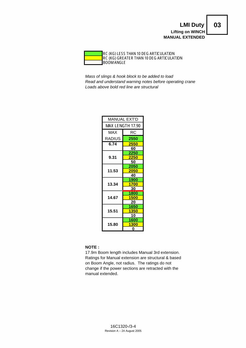
LMI Duty 03Lifting on WINCH
MANUAL EXTENDED
RC (KG) LESS THAN 10 DEG ARTICULATIONRC (KG) GREATER THAN 10 DEG ARTICULATIONBOOM ANGLE
Mass of slings & hook block to be added to load Read and understand warning notes before operating craneLoads above bold red line are structural
MANUAL EXT'D
MAX LENGTH 17.90MAX RC
RADIUS 25506.74 2550
602250
9.31 225050
205011.53 2050
401900
13.34 170030
180014.67 1500
201650
15.51 135010
160015.80 1300
0
NOTE :17.9m Boom length includes Manual 3rd extension.Ratings for Manual extension are structural & basedon Boom Angle, not radius. The ratings do notchange if the power sections are retracted with themanual extended.
16C1320-/3-4Revision A – 24 August 2005

BO
OM
LE
NG
TH
(m
)R
AD
IUS
5.97
6.50
7.00
7.50
8.00
8.50
9.00
9.50
10.0
010
.50
11.0
011
.50
12.0
012
.50
13.0
013
.50
14.0
014
.16
1000
010
000
1000
010
000
1.6
1000
010
000
1000
010
000
5154
5760
1000
010
000
1000
010
000
1000
010
000
2.0
1000
010
000
1000
010
000
1000
010
000
4650
5356
5860
1000
010
000
1000
010
000
1000
010
000
1000
010
000
2.5
1000
010
000
1000
010
000
1000
010
000
1000
010
000
3944
4851
5457
5960
1000
010
000
1000
010
000
1000
010
000
1000
010
000
1000
010
000
3.0
1000
010
000
1000
010
000
1000
010
000
9950
9950
9950
9950
3037
4246
5052
5557
5960
9750
9750
9750
9700
9700
9700
9700
9700
9700
9650
8850
7650
3.5
8500
8500
8450
8450
8450
8450
8450
8400
8400
8400
8400
7650
1930
3641
4548
5153
5557
5960
8700
8400
8400
8400
8400
8400
8400
8350
8350
8350
8100
7100
6750
6500
4.0
7550
7300
7300
7300
7300
7300
7300
7250
7250
7250
7250
7100
6750
6500
(3.8
8)19
2935
4043
4749
5254
5657
5960
7550
7400
7400
7350
7350
7350
7350
7350
7350
7350
6650
6300
6100
5850
5700
4.5
6550
6400
6400
6400
6400
6400
6350
6350
6350
6350
6350
6300
6100
5850
5700
(4.4
0)19
2834
3842
4548
5053
5456
5859
6067
0065
5065
5065
5065
5065
5065
5065
0065
0062
5059
5057
0055
0053
5051
5051
005.
058
0056
5056
5056
5056
5056
5056
5056
5056
5056
5056
0056
0055
0053
5051
5051
00(4
.90)
1827
3337
4144
4749
5153
5556
5859
5960
0054
0053
0053
0053
0053
0053
0053
0053
0053
0051
0049
0047
5046
0045
506.
051
5046
5045
5045
5045
5045
5045
5045
5045
5045
5045
5045
5045
5045
5045
50(5
.40)
(5.9
0)17
2531
3539
4245
4749
5153
5455
4900
4500
4400
4400
4400
4400
4400
4400
4400
4400
4250
4000
3950
7.0
4200
3850
3800
3800
3800
3800
3800
3800
3750
3750
3750
3750
3750
(6.4
0)(6
.90)
1624
2934
3740
4345
4749
5041
0038
0037
5037
5037
5037
5037
5037
5037
5036
0035
508.
035
5032
5032
0032
0032
0032
0032
0032
0032
0032
0032
00(7
.40)
(7.9
0)15
2328
3236
3941
4344
3500
3250
3250
3250
3250
3250
3250
3250
3250
9.0
3000
2800
2750
2750
2750
2750
2750
2750
2750
(8.4
0)(8
.90)
1522
2731
3437
3830
5028
5028
0028
0028
0028
0028
0010
.026
0024
0024
0024
0024
0024
0024
00(9
.40)
(9.9
0)14
2126
3031
2650
2500
2500
2500
2500
11.0
2250
2100
2100
2100
2100
(10.
40)
(10.
90)
1420
2223
5022
0022
0012
.00
1950
1850
1850
(11.
40)
(11.
90)
(12.
00)
RC (KG) LESS THAN 10 DEG ARTICULATION
LMI DutyLifting on RHINO HOOK
02
Mass of slings & hook block to be added to load Read and understand warning notes before operating crane Loads above bold red line are structural
Revision A – 24 August 2005
16C1320-/3-5
BOOM ANGLE OR (RADIUS AT 0 DEG BOOM ANGLE)RC (KG) GREATER THAN 10 DEG ARTICULATION

LMI Duty 04Lifting on RHINO HOOK
MANUAL EXTENDED
RC (KG) LESS THAN 10 DEG ARTICULATIONRC (KG) GREATER THAN 10 DEG ARTICULATIONBOOM ANGLE
Mass of slings & hook block to be added to load Read and understand warning notes before operating craneLoads above bold red line are structural
MANUAL EXT'D
MAX LENGTH 18.20MAX RC
RADIUS 24006.91 2400
602100
9.52 210050
190011.78 1900
401800
13.62 165030
175014.97 1450
201550
15.81 135010
155016.11 1300
0
NOTE :18.2m Boom length includes Manual 3rd extension.Ratings for Manual extension are structural & basedon Boom Angle, not radius. The ratings do notchange if the power sections are retracted with themanual extended.
16C1320-/3-6Revision A – 24August 2005

LMI Duty 05Lifting on FLYJIB (0 offset)
FLYJIBMAX LENGTH 16.78
MAX RCRADIUS 1500 RC (KG) LESS THAN 10 DEG ARTICULATION
6.23 1500 RC (KG) GREATER THAN 10 DEG ARTICULATION60 BOOM ANGLE
12008.62 1200
50970 Mass of slings & hook block to be added to load
10.69 970 Read and understand warning notes before40 operating crane850 Loads above bold red line are structural
12.38 85030770
13.63 770 NOTE :20 16.78m Boom length includes Flyjib.750 Ratings for Flyjib are structural & based
14.40 750 on Boom Angle, not radius. The ratings do not10 change if the power sections are retracted with750 the Flyjib installed.
14.68 7500
LMI Duty 06Lifting on FLYJIB (0 offset)
MANUAL EXTENDED
MANUAL EXT'DMAX LENGTH 20.83
MAX RCRADIUS 1500 RC (KG) LESS THAN 10 DEG ARTICULATION
8.25 1500 RC (KG) GREATER THAN 10 DEG ARTICULATION60 BOOM ANGLE
120011.22 1200
50970 Mass of slings & hook block to be added to load
13.79 970 Read and understand warning notes before40 operating crane850 Loads above bold red line are structural
15.88 85030770
17.43 770 NOTE :20 20.83m Boom length includes Manual 3rd extension750 & Flyjib. Ratings for Flyjib are structural & based
18.39 750 on Boom Angle, not radius. The ratings do not10 change if the power sections are retracted with750 the manual extended and Flyjib installed.
18.73 7500
16C1320-/3-7Revision B - 24August 2005

LMI Duty 07Lifting on FLYJIB (12.5 deg offset)
FLYJIB
MAX LENGTH 16.74MAX RC
RADIUS 1500 RC (KG) LESS THAN 10 DEG ARTICULATION6.70 1500 RC (KG) GREATER THAN 10 DEG ARTICULATION
60 BOOM ANGLE1200
9.03 120050970 Mass of slings & hook block to be added to load
11.03 970 Read and understand warning notes before40 operating crane850 Loads above bold red line are structural
12.63 85030770
13.78 770 NOTE :20 16.74m Boom length includes Flyjib.750 Ratings for Flyjib are structural & based
14.46 750 on Boom Angle, not radius. The ratings do not10 change if the power sections are retracted with750 the Flyjib installed.
14.64 7500
LMI Duty 08Lifting on FLYJIB (12.5 deg offset)
MANUAL EXTENDED
MANUAL EXT'D
MAX LENGTH 20.79MAX RC
RADIUS 1300 RC (KG) LESS THAN 10 DEG ARTICULATION8.73 1300 RC (KG) GREATER THAN 10 DEG ARTICULATION
60 BOOM ANGLE1120
11.64 112050920 Mass of slings & hook block to be added to load
14.13 920 Read and understand warning notes before40 operating crane820 Loads above bold red line are structural
16.14 82030770
17.59 770 NOTE :20 20.79m Boom length includes Manual 3rd extension750 & Flyjib. Ratings for Flyjib are structural & based
18.45 750 on Boom Angle, not radius. The ratings do not10 change if the power sections are retracted with750 the manual extended and Flyjib installed.
18.69 7500
16C1320-/3-8Revision B - 24August 2005
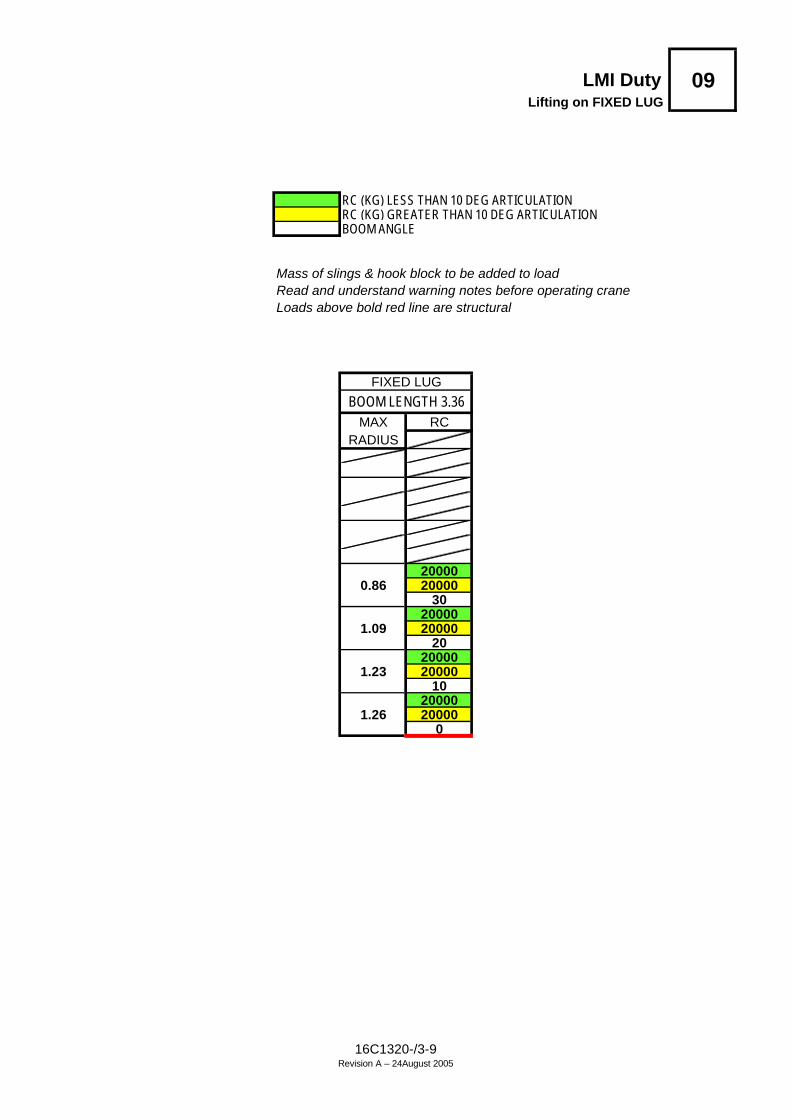
LMI Duty 09Lifting on FIXED LUG
RC (KG) LESS THAN 10 DEG ARTICULATIONRC (KG) GREATER THAN 10 DEG ARTICULATIONBOOM ANGLE
Mass of slings & hook block to be added to load Read and understand warning notes before operating craneLoads above bold red line are structural
FIXED LUG
BOOM LENGTH 3.36MAX RC
RADIUS
200000.86 20000
3020000
1.09 2000020
200001.23 20000
1020000
1.26 200000
16C1320-/3-9Revision A – 24August 2005

LMI Duty 10Lifting on INNER LUG
Mass of slings & hook block to be added to load Read and understand warning notes before operating craneLoads above bold red line are structural
RC (KG) LESS THAN 10 DEG ARTICULATIONRC (KG) GREATER THAN 10 DEG ARTICULATIONBOOM ANGLE OR (RADIUS AT 0 DEG BOOM ANGLE)
BOOM LENGTH (m)RADIUS 4.16 4.50 5.00 5.50 6.00 6.50 7.00 7.50 8.25
20000 20000 20000 19300 18100 172001.4 16000 16000 16000 16000 16000 16000
34 40 46 51 55 5819000 19000 19000 18700 17600 16500 15600 15000
1.7 16000 16000 16000 16000 16000 16000 15600 1500025 33 41 47 51 55 58 60
16950 16900 16800 16700 16650 16000 14650 141002.0 14750 14700 14600 14500 14400 14350 14300 14100
11 25 36 43 48 52 55 5716400 13800 13150 13100 13050 12950 12900 12750 11350
2.5 14300 11950 11400 11350 11250 11200 11150 11100 11050(2.06) (2.40) 24 34 41 46 50 53 57
11100 10700 10650 10600 10550 10500 104503.0 9600 9200 9150 9100 9050 9000 8950
(2.90) 23 33 39 44 48 529200 8900 8850 8800 8800 8750
3.5 7900 7650 7600 7550 7500 7450(3.40) 22 31 38 42 48
7800 7550 7550 7500 74504.0 6700 6450 6450 6400 6350
(3.90) 21 30 36 436700 6550 6500 6450
4.5 5700 5550 5500 5500(4.40) 20 29 37
5850 5700 56505.0 4950 4800 4800
(4.90) 19 315150 5000
5.5 4350 4200(5.40) 23
44506.0 3700
114300
6.15 3600(6.15)
16C1320-/3-10Revision A – 24August 2005

LMI Duty 11Lifting on OUTER LUG
Mass of slings & hook block to be added to load Read and understand warning notes before operating craneLoads above bold red line are structural
RC (KG) LESS THAN 10 DEG ARTICULATIONRC (KG) GREATER THAN 10 DEG ARTICULATIONBOOM ANGLE OR (RADIUS AT 0 DEG BOOM ANGLE)
BOOM LENGTH (m)RADIUS 4.95 5.30 5.80 6.30 6.80 7.30 7.80 8.30 9.04
20000 20000 20000 199001.4 16000 16000 16000 16000
46 50 54 5719000 19000 19000 18850 17400 15650
1.7 16000 16000 16000 16000 16000 1565041 45 50 54 57 59
17400 17300 17150 17050 16350 14700 134002.0 15200 15100 14950 14850 14750 14650 13400
35 40 46 50 54 56 5913700 13600 13500 13400 13300 13250 12350 11150 10150
2.5 11950 11850 11750 11650 11550 11500 11400 11150 1015023 31 38 44 48 52 54 57 60
11850 11150 11050 11000 10900 10850 10750 10300 93503.0 10300 9700 9600 9500 9450 9350 9300 9250 9150
(2.85) 17 29 37 42 46 50 53 5610350 9300 9250 9150 9100 9050 9000 8650
3.5 9000 8050 8000 7900 7850 7800 7750 7650(3.20) 16 28 35 41 45 48 52
8700 7900 7850 7800 7750 7700 76504.0 7550 6800 6750 6700 6650 6600 6550
(3.70) 15 27 34 39 43 487450 6850 6800 6750 6700 6650
4.5 6400 5850 5800 5750 5750 5650(4.20) 15 26 33 38 44
6500 6000 5950 5900 58505.0 5550 5100 5050 5000 4950
(4.70) 14 25 32 395700 5250 5250 5200
5.5 4850 4450 4450 4400(5.20) 14 24 33
5050 4700 46506.0 4250 3950 3900
(5.70) 13 274500 4200
6.5 3750 3500(6.20) 19
38006.9 3150
(6.94)
16C1320-/3-11Revision A – 24August 2005

LMI Duty 12Lifting in MANBASKET
MANBASKET
MAX LENGTH 13.85MAX RC
RADIUS 275 RC (KG) LESS THAN 10 DEG ARTICULATION6.06 275 RC (KG) GREATER THAN 10 DEG ARTICULATION
60 BOOM ANGLE275
8.24 27550275
10.10 275 Read and understand warning notes before40 operating crane275 Loads above bold red line are structural
11.59 27530275
12.67 275 NOTE :20 13.85m Boom length does not include Manbasket.275 Ratings for Manbasket are structural & based
13.30 275 on Boom Angle, not radius. The ratings do not10 change if the power sections are retracted with275 the Manbasket installed.
13.46 2750
LMI Duty 13Lifting in MANBASKET
MANUAL EXTENDED
MANUAL EXT'N
MAX LENGTH 17.90MAX RC
RADIUS 275 RC (KG) LESS THAN 10 DEG ARTICULATION8.09 275 RC (KG) GREATER THAN 10 DEG ARTICULATION
60 BOOM ANGLE275
10.85 27550275
13.21 275 Read and understand warning notes before40 operating crane275 Loads above bold red line are structural
15.10 27530275
16.46 275 NOTE :20 17.90m Boom length includes Manual 3rd extension275 but not Manbasket. Ratings for Manbasket are structural &
17.29 225 based on Boom Angle, not radius. The ratings do not10 change if the power sections are retracted with275 the manual extended and Manbasket installed.
17.51 2050
16C1320-/3-12Revision A – 24August 2005