~ýRASHWORTHY TROOP SEAT TESTING PROGRAM · JSAAMRDL-TR -77-13 K ~ýRASHWORTHY TROOP SEAT TESTING...
206
JSAAMRDL-TR -77-13 K ~ýRASHWORTHY TROOP SEAT TESTING PROGRAM Booing Vertol Company0 P.O0. Box 16858 Philadelphia, Penn. 19142 * !:iK Novemnber 1977 Final Report for Period May 1974 - December 1976 Aproved for puiblic release; distibuionunlimited. Prepared for A PPLIED TECHNOLOGY LABORATORY RESEARCH AND TECHNOLOGY LABORATORIES (AVRADCOM) Fort Eustis, Va. 23604
Transcript of ~ýRASHWORTHY TROOP SEAT TESTING PROGRAM · JSAAMRDL-TR -77-13 K ~ýRASHWORTHY TROOP SEAT TESTING...
JSAAMRDL-TR -77-13
K ~ýRASHWORTHY TROOP SEAT TESTING PROGRAM
Booing Vertol Company0P.O0. Box 16858Philadelphia, Penn. 19142
* !:iK Novemnber 1977
Final Report for Period May 1974 - December 1976
Aproved for puiblic release;distibuionunlimited.
Prepared for
A PPLIED TECHNOLOGY LABORATORY
RESEARCH AND TECHNOLOGY LABORATORIES (AVRADCOM)
Fort Eustis, Va. 23604

I.,!
APPLIED TECHNOLOGY LABORATORY POSITION STATEMENT
This report was prepared by the Boeing Vertol Company, a division of the Boeing Com-.pany, under the terms of Contract DAAJ02.74-C-0036. The objective of this effort wasto demonstrate the validity and practicality of a proposed draft military specification forhelicopter troop/passenger seats, This was achieved by the design, fabrication, componenttesting, static testing, and dynamic testing of lightweight forward- and aft-facing troopseats. The proposed draft military specification contained in this report has yet to becoordinated, finalized, and published. Once published and implemented, however, the *crashworthy troop/passenger seat military specification will ensure that the passengers offuture Army troop transport helicopters will be afforded a higher probability of survivalduring a crash impact.
This report has been reviewed by this Laboratory and is considered to be technically
sound. The technical manager for this program was Mr. Geroge T. Singley, IlII, StructuresTechnical Area, Technology Applications Division.
:q 1¶ LI
DISCLAIMERS
The findings In thik report are not to be construed as an official Department of the Army poultion unlaes sodesignated by other atithoriged documents.
When Government drawings, specifications, or other data are used for any puirpose other than In connectionwith a definitely related Government procurement operation, the United States Government thereby Incurs noresponsibility nor any obligetion whatsoever; and the fact thet the Government may have formulated, furnished,or in rny way supplied the said drawings, specifloations, or other date Is not to be regarded by Implication orotherwise as in any manner licensing the holder or any other person or corporation, or conveying ally rights oepe.rmission, to manufecture, use, or sell any patented invention that may In Iry way be related thereto,Trnde names cited in this roport tin not constitute art ofticini ontilorsonont or nfiproval of the use of Ruchonimnrircihil hindwnre or softwisrn,
SDISPOSITION INS1HiUCTIONS
Destroy this report when no longer needed, Do not return it to thL origihator.
............................... ...... ........... ."... .......... ........

/ ~RE ORT DOCUMENTATION PAGE ______ INSTRUCTIONS__
USAAM RD- TR-7-1.3____
9RASHW0RTiYjRO0P §EAT TESTING PROGRAM# May 074 10DeM76 1
it.PEFOMING O RGANIZATION ",W~ ANO ADDRESS IQ,0 0 SIIO a LEUTTJ! T TASK
Applied Technology Laboratory, tI.S. Army Nv77 ~Research & Technology Laborcitories
UNCLASSIFIED
Sl. DISTRINIUTION STATISMINT (ot thie Report)
Approved for public releasel distribution unlimited.
I?. DISTRIBUTION STATEMENT (of the abotraot uttered to Hfook 20, It different from Report) V
S0. AUPPLEMENTARY NOTES
IS. KEY WORMI (Continue on favr&$. aido if nec..eerv and Idontif& by' block ntumber)
Crashworthy Crash ImpulseTroop Seat Restraint SystemEnergy AttenuatorForce Deflection
20. AI16hAICT (Cloo~bt. vai vetoo " It nbegoo o -d fidenltit' by. blook number)
-)Crashworthy troop seat designs8 developed under a previous contractwere reviewed and design refinemefits were made. Componont testingwas planne.d and tests were performed. Malfunctioning componentswere redesigned and were retemted satisfactorily. A now tubular-strut energy attenuator was developed to replace the rollinghelical-wire energy attenuator which did not function properly., 1 L
14N17 EDITIONs Or I NOVe$1,lI OBSOLETE UNCLASSIFIE11ECURITY CLASSIrICATION OF THIS PAeE (Ifhom Data Mo~toed)
. .. .j... . ..
UNCLASSIFIEDSSMUITY CLASSIFICATION OF T"H1 PAO~rIhon Dole Zteren0•
20. ABSTRACT (continued).
Ctashworthy troop seats fabricated under a previous contractwere modified, with new components developed during componenttesting. Additional seats were fabricated for static testingin various crash impact attitudes. A total of six static tests,including two retests required a. a result of minor failures,i•, were performed by Dynamic Science as a subcontractor. Analysisof the test results showed that the forward- and aft-facing seatconfigurations were highly successful in meeting the test objec-tives in all attitudes, with the exception of the lateral load-ing.-' A failure occurred at a lateral loading value which waslust/Aandsr the test load objective. Minor modifications wouldperrit meeting the test objective. p
Eleven dynamic tests were performed by FAA-Civil Aeromedical [9Institute in three series of tests "eat improvements were madebetween test series, with the result that the final tests wereasuccessfully performed. Modifications to the test criteria wereincorporated in the proposed Military Specification, Seat,
:I Helicopter, Troop.
is'"
fo,,
UNCLASSIFIED
- ~ ~ ~ ~ ~~ wUNIT Y 6LAW-I ILI.A I IWN 7 . &,IW.,Dg ,td

TABLE OF CONTENTS
P age
LIST OF ILLUSTRATIONS ............. ................ 5
LIST OF TABLES ................ .................... 9
ACKNOWLEDGMENTS .................... 10
INTRODUCTION . . . . . . . . . . . . . . . 11Background. . . ..... ..................... . . 11Program Objectives ... . . . . . 12Scope .O. c. . . . . . . . . . . . . . . . . 12
CRASHWORTHY TROOP SEAT TESTING-TASK I . .. .. . .. 13Task I Requirements ... 13Review and Identification of Refinements * . : 13
Restraint System .. .. .. .. .. .. ... 15Test Plan - Component Test .......... 15
Component Testing .... .............. .. 16Test 1 . . . . . . . . .. .. . . 16Test 2 . . . . . . . . . . . 19Test 3 . . . . . . . . . . . 19'rest 4 . . . . . . . . . .. . 29 |
Detail Design'Finalization. .... 29Vertical Wire-Bending Energy Attenuator 32Toggle Latch . . . . . . . .. . .. . . .. 32Vertical Hold-Down Cable . . . . ....... 32Diagonal Strut Energy Attenuator . . . . . . . 32
Analytical Verification of Design .... 33Environmental Evaluation ........... 33Maintainability Analysis ...a ..... . . 38Reliability Analysis ............. 38Strength . . . . . . . . . . . . . . . . . . . 39
Task I Summary .. . . . . . . . . 39
CRASHWORTHY TROOP SEAT TESTINQ-TASK II ....... 40Task 11 Requirements. . . . . . . 40
Fabrication and Modification of Seat Systems.. 40Static Test Preparation ........... 42Static Test Requirements ........... 44
Static Tests and Data Analysis .......... 44Test 1 & . . . . a . . . . ................. 44Test 1B . .. ................. 53
Test 2 . . . . . .. ... . . .. * . 55Test 3 . . . . . . . .............. 60Test 4 " i n'. . . . . . . . . . 66
Seat Detail Rd sig ..... ... .... . . 71Task II Summary ...... .................. ... 73
3
. .... ....

Page
CRASHWORTHY TROOP SEAT TESTING--TASK III ........ .. 74Task III Requirements. .. . ............ 74
Fabrication and Modification of Seat Systems. . 75Dynamic Test Preparation ... ........... .. 75Electronic Instrumentation .... ........... . 76Impact Force Process ...... ............. . 77
Dynamic Testing . . . ............. ... 79Test Requirements ......... ......... .... 79Test I.................. . ............. 79Test 2 .............. ............ . . . . . 87Test 3 . . . . . . . . . ........ . . .. 90Test 4 ................ ......... ...... 94
First Series Dynamic Test Summary .............. 96Dynamic Testing and Analysis (Second Series) . 97
Test 1A ..... ..................... 98Test 3A ............. ................. ... 101Test 4A . . . . . . . . . . . . .. . . . . . 107Test 2A . . . . ................... 112Test 2B . . . .. .... . ..... 117
Second Dynamic Test Series Summary.121Dynamic Testing and Analysis (Third Seie~s) ... . 122
Test 2C . . . . . . . . . . . . . . .... . . . 122Test 1B . . . . .................. 131
CONCLUSIONS ........... . . . ........... 136
RECOMMENDATIONS . . . . . . . . . . .......... 138Draft Troop Seat Military Specification Change
Recommendations .. .. . ... ..... 138Crash Survival Design Guide Change
Recommendations. . ......... 172Rationale for Changes to TR-71-22. .......
APPENDIXESA. COMPONENT TEST PLAN . . . . . .......... 176B. STATIC TEST PLAN. ...... .............. .. 183C. DYNAMIC TEST PLAN ...... ......... . . . . . 191
4
~....... ......

LIST OF ILLUSTRATIONS
Figure Page
1 Aircraft Installation of Troop Seat Mockup. . 4
2 Vertical. Attenuator Assembly (Pre-Test) .... 17
3 Vertical Attenuator Assembly (Post-Test) . 17
4 Vertical Attenuator Force Deflection .... ...... 18
5 Floor Quick-Disconnect and Diagonal Cable(Pre-Test) . . . . . ...... 20
6 Diagonal Cable Energy Attenuator Force ADeflection. . . . . . . . . . . . . . . . . . . 21
7 Diaqonal Cable (Post-Test) ......... . . . . 22
8 Instron Tensile Tester. . . . ....... 23
9 Quick-Disconnect Adapter. . . . . . . . . . 2310 Aluminum-Strut Attenuator with Aluminum
Helical Wire. . . . . . . . . . . . . . .. . . 24
11 Unit 1 (Post-Test) ...... ................ 24
J 12 Unit 2 (Post-Test). . . . . . . ......... 25
13 Aluminum-Strut Attenuator with Stainless SteelHelical Wire ...... ............ . . . . . . . 27
14 Tubular Strut Wire-Bending Attenuator ForceDeflection. . . . ................... 28
15 Notched Wire and Pin Anchorage Test Specimen . 30
16 Quick-Disconnect and Hold-Down Cable ......... 31
17 Failed Hold-Down Cable ...... . . . . 31
18 Wire-Bending Tension/Compression EnergyAttenuator ............................ 34
19 Disassembled Wire-Bending Energy Attenuator . 35
20 Static Test Fixture .............. 3
21 Forward-Facing Seat, Forward Loading. ...... 45
- �t + " 'Ib
Figure Page
22 Pretest, Floor Warped ........ ........... ... 45
23 Floor Unwarped ........... ................. ... 46
24 Floor Warped .... ........ . ..... ......... ... 46
25 Test 1 - Forward-Facing Seat, Forward Load/Deflection ............. .................. 48
26 Failed Strap Anchor . . . ............ 49
27 Post-Test Seat Condition ..... ............ .. 49
28 Test lA - Forward-Facing Seat, Forward Load/ 50Deflection . ....................
29 Lapbelt Anchor Adapter. . ............ .50
30 Post-Test Racked Position .... ........... .. 51
31 Failed Strut Attachment Fitting ........ 51
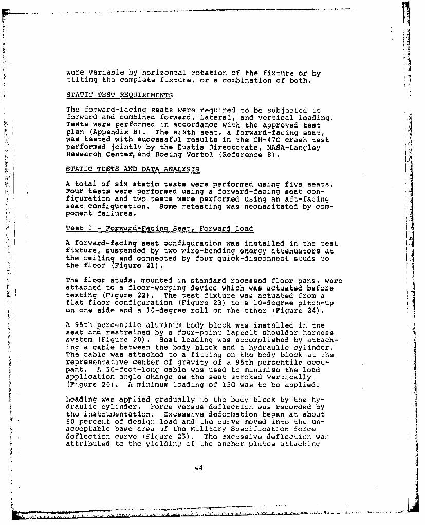
32 Seat Back Tube Crack ......... . . . . . 52
33 Test lB - Forward-Facing Seat, Forward Load/ 52Deflection ...................
34 Test lB - Lapbelt and Shoulder Strap Loads . 54
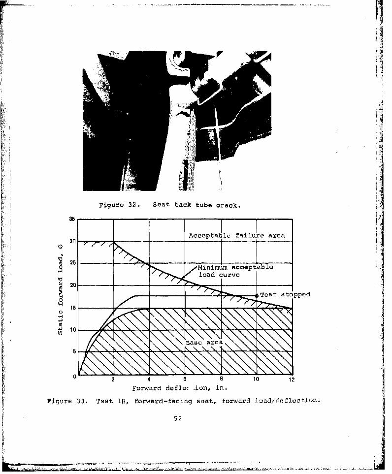
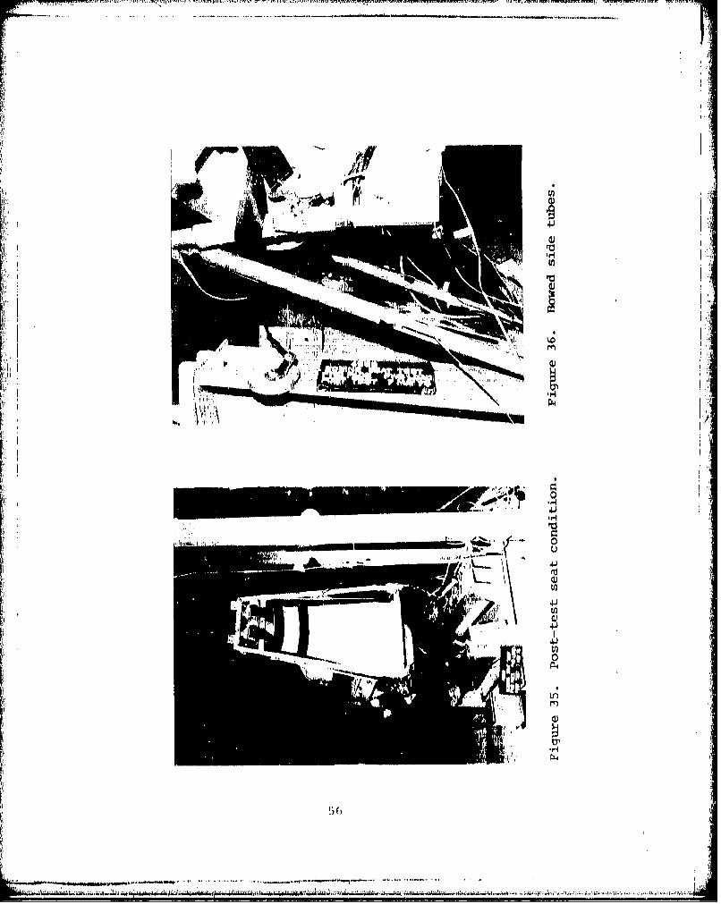
35 Post-Test Seat Condition ..... ......... .... 56
36 Bowed Side Tubes ......... .............. .... 56
37 Stroked Vertical Attenuators .... ........ ... 57
38 Stroked Diagonal Attenuators .... ........ ... 57
39 Pre-Test Aft-Facing Seat, Back Loading. . . . 58
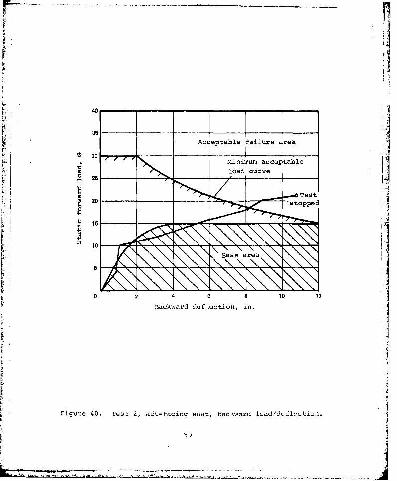
40 Test 2 - Aft-Facing Seat, Backward Load/ 59Deflection . . . . . . .............
41 Post-Test Seat Condition ..... ............ .. 61
42 Stroked Vertical Attenuators .............. .. 62
43 Stroked Diagonal Attenuators .... .......... .. 62
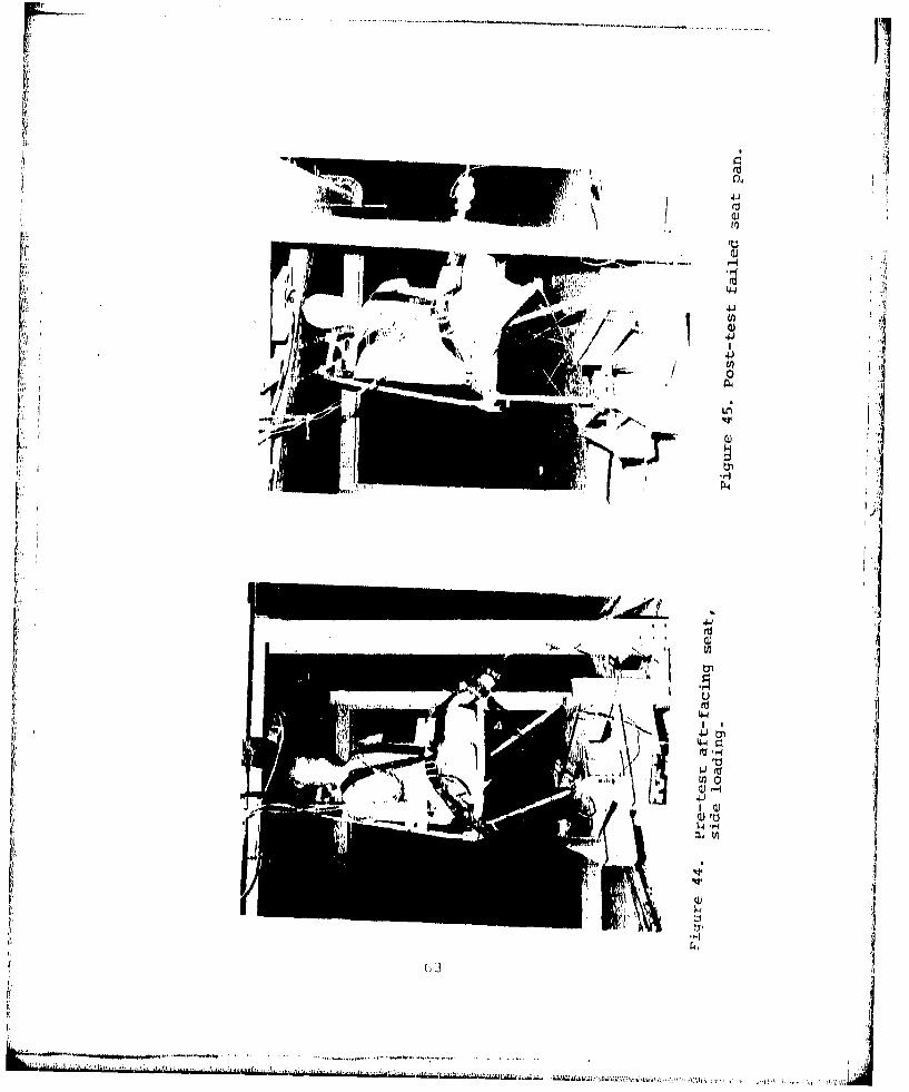
44 Pre-Test Aft-Facing Seat, Side Loading. .... 63
6
Figure Page
45 Post-Test Failed Seat Pan ..... ....... .. ... 63
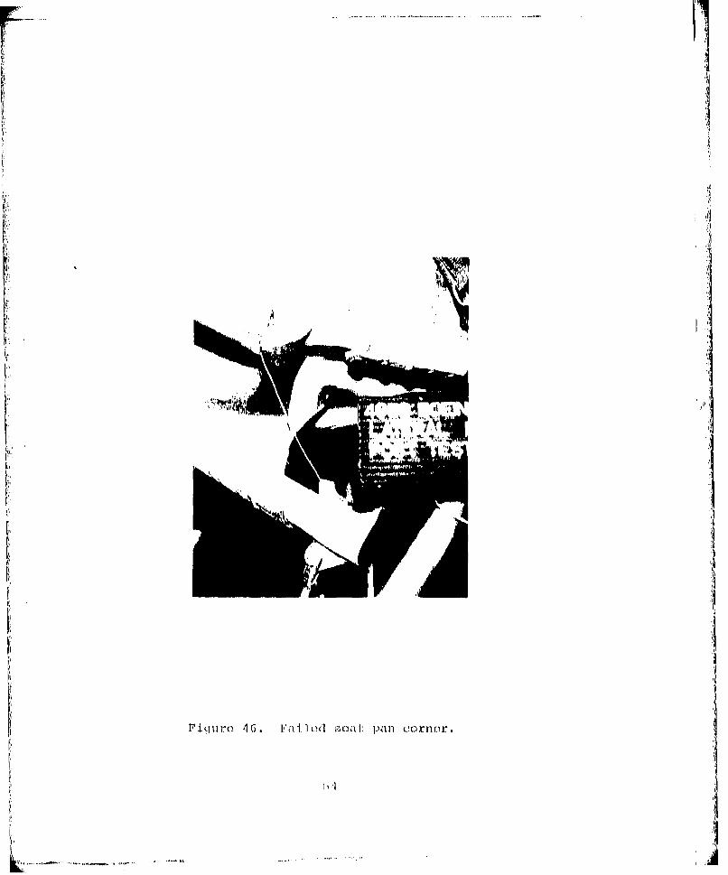
46 Failed Seat Pan Corner .... ............ .... 64
Oil. 47 Test 3 - Aft-Facing Seat, Lateral Load/Deflection .. .. ........... . .. .. .. ..... 65
48 Lapbelt and Shoulder Strap Loads ............ 67
49 Pre-Test Forward-Facing Seat, Combined Three-Axis Loading . . . . . . . . . . . . . . . .. . 68
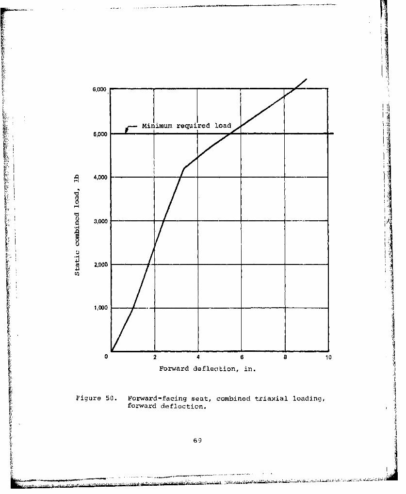
50 Forward-Facing Seat, Combined Triaxial Loading,Forward Deflection ...... ............... ... 69
51 Stroked Vertical Attenuators ..... ...... .... 70
52 Post-Test Seat Condition. . . . . . . . . . . . 70
53 Lapbelt and Shoulder Strap Loads. . . . . . . . 72 !1
54 Pre-Test I - Three-Axis Loading . . . . . . . . 80
55 Post-Test I - Three-Axis Loading. . . . . . 80
S56 Test 1 - Sled Deceleration Time History . 81 . 8
57 Test 1 - Vertical Acceleration, Dummy Pelvis 83
58 Pre-Test 2 - Three-Axis Loading ........ ..... 88
59 Post-Test 2 - Three-Axis Loading ...... ...... 88
60 Stroked Vertical Attenuators ...... ........ 89
61 Stroked Diagonal-Strut Attenuators ..... ..... 89
62 Test 2 - Vertical Acceleration Dummy Chest. 91
63 Test 2 - Sled Deceleration Time History. . . 92
64 Pre-Test 3 - Forward Yaw Loading ..... ....... 93
65 Post-Test 3 - Lapbelt Failure .... ........ ... 93
66 Pre-Test 4 - Forward Yaw Loading .......... ... 95
67 Post-Test 4 - Seat Back Failure ... ....... ... 95
7
-. ~..... . ......

p)
____ Pae
68 Pre-Test 1A - Three-Axis Loading ....... ... 99
69 Post-Test 1A - Three-Axis Loading ....... ... 99
70 Test 1A - Sled Deceleration Time History . 100
71 Test 1A - Vertical Acceleration, Dummy Chest 100
72 Pre-Test 3A - Forward Yaw Loading ......... 102
73 PosU-Test 3A - Forward Yaw Loading... .... 102....
74 Stroked Vertical Attenuators .......... ... 103
75 Stroked Diagonal-Strut Attenuators ..... ... 103
76 Test 3A - Sled Deceleration Time History . . . 104 I77 Test 3A - Longitudinal Acceleration, Dummy
Pelvis and Chest ................ 105
78 Test 3A - Vertical Acceleration, DummyPelvis and Chest . . . . . . . . . ...... 106
79 Pre-Test 4A - Forward Yaw Loading........... 108
80 Post-Test 4A - Forward Yaw Loading ....... 100
81 Upper and Lower Stroked Attenuators ......... 109
82 Test 4A - Sled Deceleration Time History . . 110
83 Test 4A - Vertical, Longitudinal, and LateralAcceleration, Dummy Chest ..... ........... . 111
84 Pre-Test 2A - Three-Axis Loading ......... .. 113
85 Post-Test 2A - Three-Axis Loading. . .. . 113
86 Stroked Vertical Attenuators ........... ... 114
87 Test 2A - Sled Deceleration Time History . . . 115
88 Test 2A - Vertical and LongitudinalAcceleration, Dummy Chest ............ .16
89 Pre-Test 2B - Three-Axis Loading ....... 118
90 Post-Test 2B - Three-Axis Loading ......... ... 118
8
-. -
Figur~e Page
91 Test 2B - Sled Deceleration Time History. . .. 119
V 92 Test 2B - Vertical, Longitudinal, and LateralAcceleration, Dummy Chest .... ........... .. 120
93 Slack-Loop Energy-Attenuator Wire ....... 123
94 Forceý/Deflection Comparison, Tight andSlack Loop... ..... .................. .124
95 Effect of Wire Lubrication on AttenuatorStroking Forces . . . ................ 125
96 Pre-Test 2C - Three-A:<is Loading. ........ 126
97 Post-Test 2C - Three-Axis Loading ....... 126
98 Test 2C - Sled Deceleration Time History. 128
99 Test 2C - Vertical, Longitudinal, and Lateral iiAcceleration on Dummy Chest . ......... 129
100 Test 2C - Vertical, Longitudinal, and LateralAcceleration on Dummy Pelvis .... .......... ... 130
101 Pre-Test lB - Three-Axis Loading. . . . . ... 132
102 Post-Test lB - Three-Axis Loading ......... .. 132
103 Seat Impact With Dummy's Legs .... .......... 133
104 Test lB - Sled Deceleration Time History ....... 134
105 Test 1B - Vertical Acceleration on DummyPelvis and Chest ........ .............. . . . 135
A-1 Vertical Enurgy Attenuator and Toggle Latch 17Test Specimen . . .......... ... . .
A-2 Lateral Energy/Attenuator and Floor Stud Quick-Disconnect Test Specimen. . . . ......... 179
A-3 Longitudinal Energy/Attenuator and Floor Stud
Quick Disconnect Test Specimen ............ ... 180
A-4 Vertical Holddown Cable and Quick-Disconnect"Test Specimen . . .......... . . . . . . .
B-1 Seat Installation 184
••, , ,- , ,,,. 1' ' ' .'.,1',.. ,•• '1• •" . ... .• <7• , 1- ,,1• ; ,•' ' "•-• ' -• '. , •• ,,, ,J ,,• •,. 5 k,•:•, • •.•,9••
•"'t!,!•; ,!a,':•-•',',:•!• •,:: !:;u,• ,t•:;!•'=:•:•"• '"••"!" 'J!• ' •' °':: •L'.... ........... ....... ........ ........ •
I
Figure Page
B-2 ceiling Connection Fitting ..... .......... . 185
B-3 rloor Warpaqe Requirement .... ........... ... 186
C-I Seat Installation ....... ............ ... 192
C-2 Ceiling Connection Fitting ............ 193
C-3 Impact Pulse and Seat Orientation, Test 1 196
C-4 Impact Pulse and Seat Orientation, Test 2 197
C-5 Impact Pulse and Seat Orientation, Test 3 . . . 198
C-6 Impact Pulse and Seat Orientation, Test 4 . . . 199
LIST OF TABLESPai.e
Table
1 Instrumentation .. ..... .8
2 Occupant Weights. .. .......... 85
3 Seat Stroke . . . . . . . ............ 86
4 Summary of Dynamic Test Condi+ions ....... 137
ACKNOWLEDGMENTS
Appreciation is extended to Stan DesJardins and Alan Lane ofDynamic Science Inc., Phoenix, Arizona, who performed thestatic testing, and to Ed Trout and Dick Chandler, for theirsupport during the dynamic testing at the FAA-Civil Acro-medical Institute, Oklahoma City, Oklahoma.
10
,I
INTRODUCTION .
BACKGROUND
The poor crash impact performance of helicopter troop seatsdesigned to current military specifications was revealed bythe U.S. Army in the early 1960's through accident investiga-tions, full-scale crash tests, and critical review of theapplicable specifications. It was discovered that numeroustroop seat occupants were being injured during moderate
til impacts because of inadequate upper torso restraint, andinadequate seat strength. The ultimate load requirementamounted to approximately 8G vertically on the seat pan,3G on the back and 10 side loading. There were no significantmeans of vertical crash-force attenuation, and testingcriteria and methods were inadequate. Crashworthiness designcriteria for improved troop seat design were developed andpublished in TCREC Technical 'Roport 62-79 (Reference 1)."Several experimental troop seat concepts designed in accor-dance with theae criteria were subsequently developed andtested as described in TRECOM Technical Reports 63-62(Reference 2) and 65-6 (Reference 3). These efforts (1)demonstrated that the TCREC TR 62-79 crashworthiness design,criteria are technically attainable, and (2) led to theinclusion of these criteria in USAAVLABS TR 67-22 (Reference4), "Cr&.sh Survival Design Guide".
!41Development of crashworthy troop seats has continued at a slowpace because of the formidable list of requirements which theseats must meet. Some of those requirements are as follows:
ITurnbow, J.W. , et al. , CRASH INJURY EVALUATION, Aviat-ionCrash Injury Research, Phoenix, Arizona; TCREC Technical"Report 62-79, U.S. Army Transportation Research Command,Fort Eustis, Virginia, November 1962.
2 Turnbow, J.W., et al., CRASH INJURY EVALUATION, DYNAMIC TESTOF AN EXPERIMENTAL TROOP SEAT INSTALLATION IN AN 11-21 11ELI-COPTER, Aviation Safety Engineering and Research, Phoenix,Arizona; TRECOM Technical Report 63-62, U.S. Army Transporta-tion Research Command, Fort Eustis, Virginia, November 1963.
3Weinberg, L.W.T., CRASHWORTHINESS EVALUATION OF AN ENERGY-ABSORPTION EXPERIMENTAL TROOP SEAT CONCEPT, Aviatiun SafetyEngineering and Research, Phoenix, Arizona; USATRECOM Tech-nical Report 65-6, U.S. Army Transportation Research Command,Fort Eustis, Virginia, February 1965, AD 614582.
4Turnbow, J.W., et al., CRASH SURVIVAL DESIGN GUIDE, AviationSafety Engineering and Research, Phoenix, Arizona; USAAVLABSTechnical Report 67-22, U.S. Army Aviation Materiel. Labora-tories, Fort Eustis, Virginia, December 1967, AD 656621.
ii
• , • . .. ... . . . . . . ...... .. . . .. ... ....... ......... .,_ ,. . .... • o,.,.- ,-• .,- . . . ... ...... ... ....... . .. .. . .. . . 1
Low cost and weight, high strength, stowability in a smallspace, rapid removal and folding, adjustability for troopswith and without field equipment, adequate support forshoulder restraint, operational simplicity for troopsunfamiliar with rcstraint devices, clear seat area forrapid ingress and egress, stabilized stroking under allimpact attitudes, energy"attenuating devices which arereliable, repeatable, and not affected by environmentalconditions, and are adaptable to the wide range of troopand equipment weights.
A crashworthy troop seat was selected from a number of pro-posed concepts and was developed to meet the above require-ments. This development and operational suitability evalua-tion is discussed in USAAMRDL-TR-74-93 (Reference 5).Structural strength and crash impact energy attenuation featuresremained to be evaluated and are the subject of this report.
PROGRAM OBJECTIVES
The crashworthy troop seat testing program principal objectives A[ were as follows:
* Determine satisfactory functioning and strengthof critical components such as energy-attenuatingdevices.
S Determine seat system stability and strength duringcrash impact loading and stroking.
* Determine seat's capability of attenuating crash impacton occupant.
e Substantiate or revise a proposed Seat, Helicopter,Troop Military Specification based on test data.
SCOPE
The crashworthy troop seat testing program was divided intothe following tasks:
Task I - System analysis and component testingTask 11 - Static testing and analysisTask IIl - Dynamic testing and analysis
Reilly, M.J., CRASHWORTHY TROOP SEAT INVESTIGATION, BoeingVertol Company, Philadelphia, Pennsylvania; USAAMRDL TechnicalS~Report 74-93, Eustis Directorate, U.S. Army Air MobilityResearch and Development Laboratory, Fort Eustis, Virginia,
December 1974, AD A007090.
k 12MtJ
CRASHWORTHY TROOP SEAT TESTING - TASK I
TASK I - REQUIREMENTS
The required Task I effort was as followsi
1. Review troop seat designs performed under ContractDAAJ02-72-C-0077 (Reference 5) and identify componentsrequiring design refinements.
2. Survey restraint systems (using commercially avail-able components).
3. Prepare test plan for component tests.
4. Test components.5. Finalize detail design to comply with test results.6. Analytically verify design to assure that it complies
with environmental, strength, crash-force attenuation,and other performance requirements of the draftMilitary Specification, Seat, Helicopter, Troop.
7. Establish test plan for static tests.
Each of these areas is discussed in the above order.
REVIEW AND IDENTIFICATION OF REFINEMENTS
Drawings and analysis of the crashworthy forward-facing troo;seat developed under USAAMRDL Contract DAAJ02-72-C-O007 werereviewed to determine the adequacy of the troop seat forstatic and dynamic testing. Detailed stress analysis had beenconducted on the principal seat structure and the seat wasbuilt in accordance with this analysis (Figure 1). Therefore,the seaty was assumed to be capable of withstanding the tests.A preliminary analysis had been performed on the small compo-nents, such as toggle latches and floor quick-disconnects. Adetailed analysis was not performed as it would have beencomplex, and individual tests of the components were deter-mined to be the least expensive approa.-h. The restraintsystem was adequate for the mock-up demonstrations (Figure 1)but did not meet the static and dynamic test requirements.Therefore, design of a new restraint system of adequatestrength was necessary, using available components.
The headrests on the troop seats used for mock-up demonstra-tion were of thin plywood and had to be replaced for therearward dynamic loading condition. The foam pads used weresoft and required replacement with an energy absorbingmaterial.
13
-7 7 OV,:s F2J.gfl I\,,.A ;!0A, Y .V,,M S _I Z;

A,
miy;
I~ ~~~~~~~~o Lruo1AtaFLin; i tlnaFi op seIL. loodk-11p.
T."i(.-urc Air c , if L t j, I(-_
The mock-up seat drawings showed only a forward-facingconfiguration. Modifications to the drawings were necessaryto add details for an aft-facing seat configuration. Forward-facing seats can be converted to aft-facing seats by adding abracket on the seat pan rear tube and by connecting thediagonal strut at the back of the seat instead of the front.Floor quick-disconnects used at the back of seats are alsorequired at the front of aft-facing seats to permit thediagonal strut to be connected to the floor. Front diagonalcables require connection to the attenuator strut quick-dis-connecting rather than to the individual disconnects used onforward-facing seats.
RESTRAINT SYSTEM
A survey was made of available off-the-shelf restraint systemcomponents and materials which would meet the strength andelongation requirements of the draft Military Specification,Seat, Helicopter, Troop. The buckle is the principalcomponent of the system. A buckle with a minimum of fourconnecting points is required. Two attachments are for thetwo lapbelt ends and the other two are for the double shoulderstraps. Design load requirements on the buckle are 4000 lbof tension on the lapbelt connections and simultaneous loading(f 4000 lb on each of the shoulder strap connections. Theonly available buckle purporting to meet these requirementswas a slide release buckle.An available polyester webbing that meets the lapbelt and shoul-der harness requirement of 5 percent maximum elongation at4000-lb design load tensile strength was found. The webbingwas 2 in. wide, 0.065 in. thick, had a 9024-lb minimum breakingstrength, and was developed for the auto industry. Commerciallyavailable shoulder harness reels at 2000-lb design load werefound which adequately met the dynamic test loads.
TEST PLAN - COMPONENT TEST
A test plan for static-testing components of the troop seatwas prepared and is attached as Appendix A. The plandiscusses testing of 11 components separately or in combina-tion with other components. The following components areincluded in the tests
1. Seat-tensioning turnbuckle
2. Seat-tensioning toggle latch
3. Vertical energy attentuator (wire-bznding)
4. Front diagonal energy-attenuating cable
15
I I I I u
5. Front quick-disconnect (floor attachment)
6. Front floor quick-disconnect stud
7. Diagonal stabilizing strut energy attentuator
8. 8ack quick-disconnect (floor attachment)
9. Back floor quick-disconnect stud
10. Vertical hold-down energy-attenuating cable
11. U-bracket and back quick-disconnect (floor attachment)
COMPONENT TESTING
Testing was performed in accordance with the proceduredescribed in the test plan (Appendix A). As a result ofproblems encountered, some retests were necessary. Thetests performed were as follows:
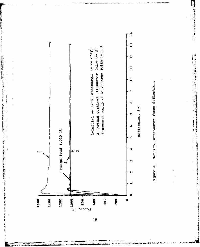
Test 1 1A combination of components was used in Test 1. Thesecomponents consisted of a seat-tensioning turnbuckle, aseat-tensioning toggle latch, and a vertical energyattenuator. Adapters were made for installing the assemblyin the Instron tensile test machine (Figure 2). A tensionload was applied to the specimen in stepped increments andinspections for deformation were made. The test wasstopped when deformation of the toggle latch occurred(Figure 3). A maximum load of 1300 lb was recorded.There was no stroking of the wire-bending attenuator.The design stroking load is 1020 lb.
A second run was made, testing only the wire-bendingattenuator. The peak starting load was recorded as1555 lb, with a running load of 1400 lb (Figure 4). Itwas evident that the wire size was too large, so a newwire was fabricated using 0.100-in. diameter wire.
A third run was made using only the wire-bendingattenuator. The design stroking load of 1020 lb wasalmost exactly achieved, varying plus and minus 10 lbfrom a 1030-lb mean (Figure 4).
The fourth run was .. de using the 0.100-in. diameter wire-bending attenuator in an assembly with the turnbuckleand modified toggle latch. The stroking force varied onlyslightly from the 1020-lb design load line, with fluctua-tions ot plus and minus 5 lb. No deformation of thetoggle latch occurred (Figure 4)
IG
. . . . . . . . . . . .. .,..... ... ............ ....... ........ . . . . . . . . .[

IIýH 41
4J V)
tAU)
4IJ(d
"I Mi
U)4
04A
.17
r7 -1
,r4 H
tn 0H
040
r4.
44)
N 0 oNocEt r-4
q' T mxo

Test 2
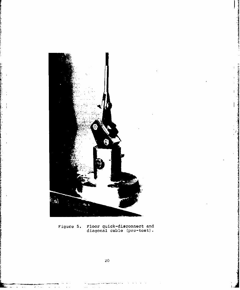
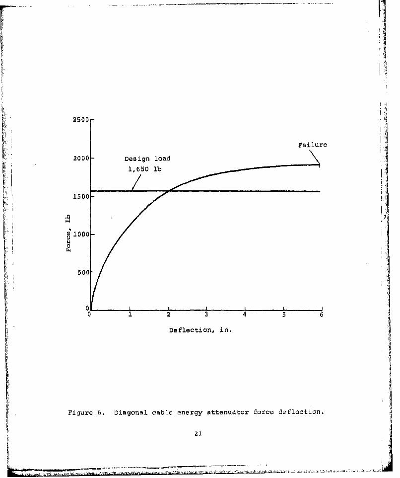
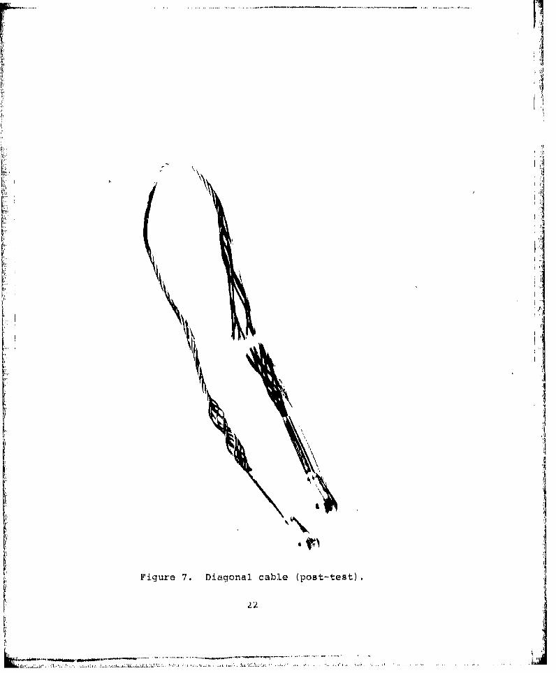
Components included in Test 2 were the front diagonalenergy-attenuating cable, floor quick-disconnect fitting,and floor quick-disconnect stud. The test specimen wasinstalled in the Instron tensile test machine, usingadapters to orient the end fittings as installed on theseat (Figure 5). The assembly was pulled at a rate of10 in. per minute with stops made at intervals to inspectfor deformations. A curvilinear force deflection curvecharacteristic of tensile yielding materials, was producedwith an average force level approximately on the designforce level of 1650 lb (Figure 6). The cable broke at2000 lb after stroking 6 in. (Figure 7). This wouldpermit an 8-in. lateral seat stroke, which is morethan the lateral stroke needed. All of the remainingcomponents in the assembly withstood the 2000-lb loadwithout deformation.
Test 3
The telescoping-tube rolling helical-wire energyattenuator was tested in conjunction with the floor quick-disconnect fitting and the floor quick-disconnect stud.The attenuator was constructed using 6061 aluminum tubingand 2C24 aluminum wire. The assembly was placed in theInstron tensile test machine (Figure 8). Adapters wereused to hold the quick-disconnect fitting in the sameorientation as used for the troop seat installation(Figure 9).
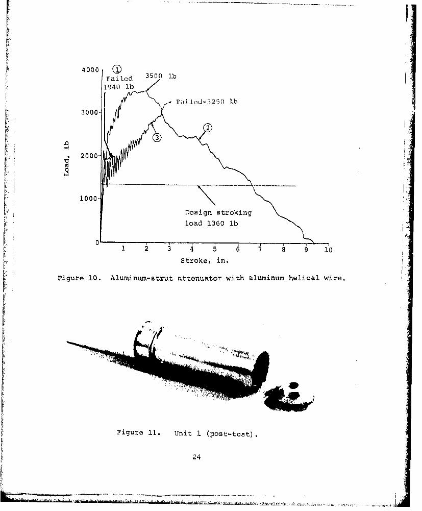
The design stroking load for the attenuator is 1360 lb.Tensile loading was applied to the attenuator in steppedincrements until the load reached 1940 lb. At this load,the end fitting pulled out due to a weld failure (Figures10and 11). The attenuator stroked only 0.63 in.
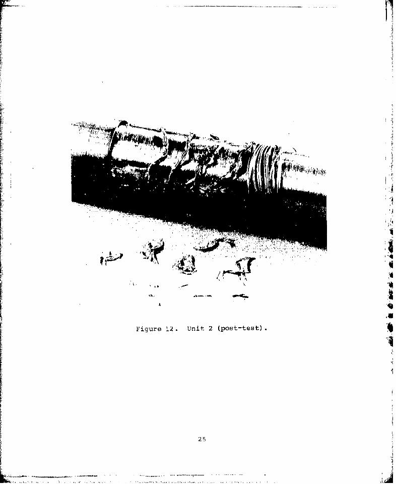
A second attenuator unit was tested and required a 3500-lb force to cause 1 in. of stroke. After stroking 2 in.,the force required to pull the attenuator dropped rapidlyuntil it reached zero load at 9 in. of stroke (Figure 10).The wire was exposed in this test and showed signs ofbeing fused together (Figure 12). Rolling of the helicalwire element did not occur as intended,
The floor quick-disconnect fitting and floor stud with-stood the 3500-lb load without deformation. This load is250 percent of design load. A third attenuator unit wastested and it failed in the same manner as the first afterreaching a load of 3250 lb. The unit had stroked 3 in. atthe point of failure (Figure 10).
:: • -.-. u . • . .. . ~~~~~~~~ ~~~~~~~~.... .................... . .. .. . . .. .. ..... ........... . .i!
F Ii
• '. .........
II
Figure 5. Floor quick-disconnect anddiagonal cable (pro-test).
20
w ,. .. . . .. . .. . . . .. . .L , I•
2500-
Fai lure
2000 Design load
1,650 lb
1500"
0) 1000
500
060 1 2 3 4 5 6
Deflection, in.
I'
Figure 6. Diagonal cable energy attenuator force cdhflaction.
,, ii
1> I' *. I
Ii'IN
I
N IIN
Fiqure 7. Diagonal cable (post-test).
22 ./
U.-

wIT:, w
44IutHU
9144
4J
4J
4,
4000 QFailed 3500 lb
1940 lb
SFai.Iod-3250 lb3000-
23
2000'-
1000.
Design stroking
load 1360 lb
0'I
0 ~~~Stroke, sin. 6 7 8 9 1
Figure 10. Aluminum-strut attenuator with aluminum helical wire.
Figure 1. Unit I (post-test).
24
........ ..'..
... * .. ..
Figure 12. Unit 2 (post-test).
25

The units were returned to the vendor for redesign and 17new units were returned. These new units were the sameas the first, except that a stainless steel helical wirewas used in place of the aluminum wire.
A test was conducted on a new unit and it failed to reachthe design stroking load of 1360 lb. It peaked at 1090lb and rapidly fell to 800 lb at 1-in. stroke, and to 450lb at 7-in. stroke (Figure 13). Seven tests were conductedon the new units and a wide range of irregular patternswere produced, none reaching the design stroking loadrequirements (Figure 13).
Cause for the failure of the units to perform properlywas investigated. It was observed that the surface of theouter tubes had ripples around their circumference and itwas assumed that these were in the area of the helicalwire. From this, it was concluded that the wire wascausing the aluminum tube to cold-flow. Pressure betweenthe wire and the inner and outer tubes was relieved by thecold flowing. The wire was captured in the grooves, and dwhen load was applied to captud the wire slid and didnot roll as intended. Relief of pressure on the wire andthe cold-flow grooves resulted in low resistance to load-ing and produced irregular load/deflection patterns.
A new attenuator was designed and fabricated and develop-mental tests were performed. This new configurationconsists of a telescoping-tube strut with a wire-bendingelement inside the tubeF details are discussed below.
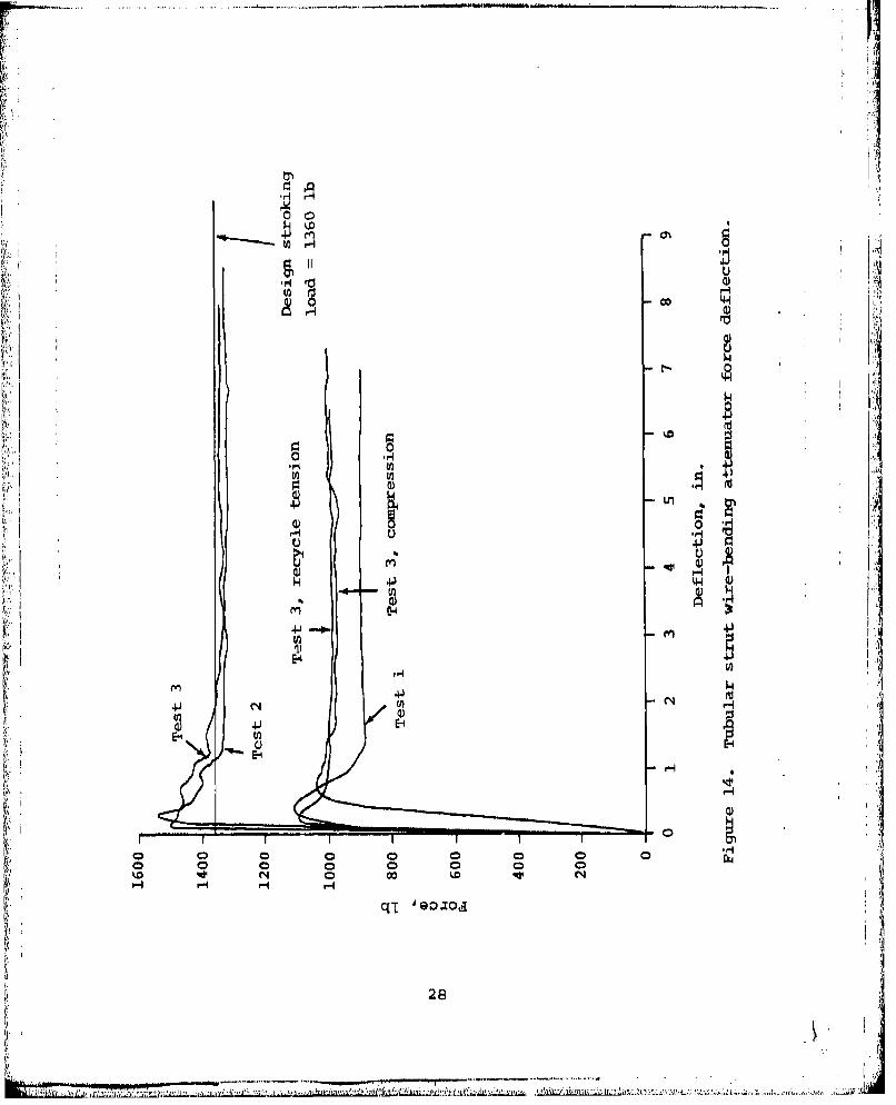
The initial tensile test produced a flat force deflection
curve, but the stroking load was 30 percent below thedesign load (Figure 14). Redesigns were made to the wire-
bending element to increase the bend angle of the wire. A
second unit was tested in tension and the force deflectioncur e v lue wee within design tolerances (Figure 14).
curve values were witi design the unit and the forceCompressiun tests were conducted onth uni andt foc
level dropped alpproximately 20 percent. The unit wasagain recycled in a tension mode and the force level of
the compression mode was maintained (Figute 14).
Testing of the first two units was accomplished without awire terminal fitting at the end of the strut. The wireends were clamped in the test machine for the tests. Amethod for terminating the wires had not been determinedat the time of testing.
Individual tests were made of two terminal types. Thefirst type attached the wires by swaging, and when tested,
the wires pulled out at 50 percent of design load. Thesecond type attached the wires by pinning; details are
26

. . . . . . . . . . . -. " - ,'- , - - - - - - - . - - - - - - - - - - - - - -. .. -.....
CH
Hl 0
C14 V) H
HH
N cH- -
27H
Ai.........
go1W 0d
'A'
0-
0.40
440 )u
au)
H H H H ~ G044
Lai
28
described below. This unit was tested in destruction andsatisfactorily reached 200 percent of design load (Figure
A third energy-attenuator test specimen was fabricated,incorporating the pinned-type wire termination. Testswere performed on this unit and function and force/deflection results were satisfactory (Figure 14).
Test 4
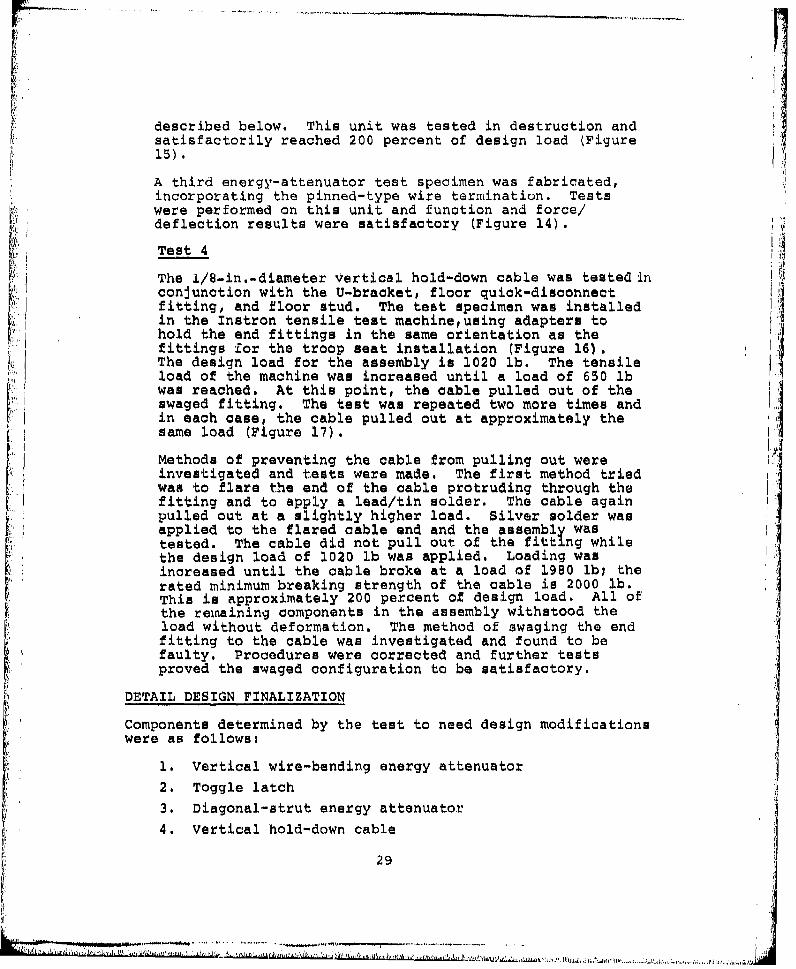
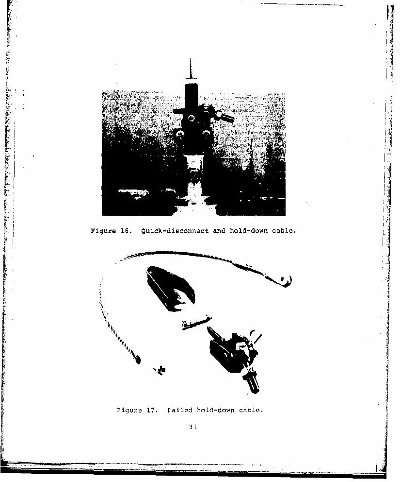
The l/8-in.-diameter vertical hold-down cable was tested inconjunction with the U-bracket, floor quick-disconnectfitting, and floor stud. The test specimen was installedin the Instron tensile test machine,using adapters tohold the end fittings in the same orientation as thefittings for the troop seat installation (Figure 16).The design load for the assembly is 1020 lb. The tensileload of the machine was increased until a load of 650 lbwas reached. At this point, the cable pulled out of theswaged fitting. The test was repeated two more times andin each case, the cable pulled out at approximately thesame load (Figure 17).
Methods of preventing the cable from pulling out wereinvestigated and tests were made. The first method triedwas to flare the end of the cable protruding through thefitting and to apply a lead/tin solder. The cable againpulled out at a slightly higher load. Silver solder wasapplied to the flared cable end and the assembly wastested. The cable did not pull out of the fitting whilethe design load of 1020 lb was applied. Loading wasincreased until the cable broke at a load of 1980 lbi therated minimum breaking strength of the cable is 2000 lb.This is approximately 200 percent of design load. All ofthe remaining components in the assembly withstood theload without deformation. The method of swaging the endfitting to the cable was investigated and found to befaulty. Procedures were corrected and further testsproved the swaged configuration to be satisfactory.
DETAIL DESIGN FINALIZATION
Components determined by the test to need design modificationswere as follows:
1. Vertical wire-bending energy attenuator2. Toggle latch3. Diagonal-strut energy attenuator4. Vertical hold-down cable
29
"" - ,1

rj
.. IJ
I.u
rL4
300
:L
'U
Lfl
,,..I
':3
'NIII
rA
Figure 16. Quick-disconnect and hold-down cable.
MIS.31
-'K '--------

VERTICAL WIRE-BENDING ENERGY ATTENUATOR
The stroking load for the initial wire-bending energyattenuator in the first test was found to be in excess of thedesired value, causing deformation of the attachment compo-nents. To reduce the load, the wire size was reduced to0.100 in. Improvements were otade in the end of the wire bychanging from an inverted U shape to an inverted V shape toimprove attachment to the toggle latch. The initial configu-ration required threading through holes in the toggle latch.The revised configuration permits a simple pin attachment.The test of the revised unit proved to be satisfactory.
S~ TOGGLE LATCH
Deformation of the toggle latch experienced during testingnecessitated its being stiffened. The channel-shaped latchwas reinforced by adding another channel section to form abox. The hinge ears on the original channel, which deformedin the teat, were doubled in thickness by the added channel.Heat treatment of the 4130 steel used for the channels to16OKSI further improved the strength. Attachment of thewire-bending attenuator to the latch was improved by the newbox configuration.
VERTICAL HOLD-DOWN CABLE
Attachment of the swaged fitting to the vertical hold-downcable failed to hold at the required load during testing.Silver-soldering the cable to the fitting proved to besatisfactory for meeting the load requirements but requiredspecial procedures during fabrication. High heat is neededto apply the silver solder to the cable, and heat annealsthe cable, reducing its strength. Procedures for cool~ingthe cable during soldering were required.
A decision was made that the best approach was to improvethe swaging technique and to proof-test the cable assemblyafter swaging. Subsequent cable assemblies were fabricatedusing the improved swaging techniques, and proof tests to1100 lb were madel this load is slightly greater than thedesign load.
DIAGONAL-STRUT ENERGY ATTENUATOR
The telescoping-tube energy attenuator using the rollinghelical wire principal was found to be unsatisfactory duringcomponent testing. A substitute attenuator was developedwhich uses a wire-bending principle similar to that used Inthe vertical attenuator.
32
.. ............. xiiivsrzB~
Wire-bending attenuators h,.ve been found by Boeing tests tobe predictable, reliable, and free of environmental problems.The one disadvantage of the wire-bending attenuator is thatit cannot take compression. The problem then was. to developan attenuator which will function in tension or compressionwhile the wire-bending element operates in tension.
An attenuator was developed which uses telescoping aluminumtubes similar to the attenuator it replaced. A cap isplaced on the inner end of the inner tube (Figure 18).Music wire of 0.100 in. diameter, in the shape of a hairpinis looped through the cap, and the two free ends are securedto a stud in the outer end of the inner tube. A trolleyconsisting of three rollers sandwiched between two platesbends the wire as it moves back and forth on the wire. Thetrolley is pinned to the outer tube and a slot is providedin the inner tube to allow the trolley to move relative tothe inner tube (Figure 19).
considered. The ends of the wire were roughened and then
swaged in the fitting. Tests proved this method to be un-satisfactory. An Electroline wedge gripper was consideredbut was rejected due to size and weight. A third approachwas to use the same study fitting used for swaging, but topin the wires to the fitting. A hole was drilled between thetwo wire insert holes and the wires were notched. A pin wasinserted in the hole to retain the wires (Figure 15). Teststo destruction were made and failure occurred at 200 percent.of design load.
ANALYTICAL VERIFICATION OF DESIGN
The troop seat design was reviewed to determine its compliancewith environmental requirements, maintainability, reliability,and other performance requirements of the draft MilitarySpecification; Seat, Helicopter, Troop. (See Recommendationssection of this report on P.138 )
Environmental Evaluation
An evaluation was made of the ability of the troop seat designto comply with the environmental requirements of the MilitarySpecification/ Seat, Helicopter, Troop, as detailed in theenvironmental test methods of MIL-STD-810. The followingenvironmental factors were evaluated:
MIL-STD-810, Military Standards, Environmental TestMethods.
33
414
U NI
t-4 *-
K 0 H
34H
44"4

,r.I
K -.SIIi
0•CIIl
0) y

. Temperature--The seat system was reviewed to deter-mine whether materials and construction would with-stand nonoperating exposure as well as deliverspi cified performance when subjected to the highand low temperature specified in Environmental TestMethod 501, Procedures I and II, and Method 502 ofMTL-STD-810. The following conditions can be exper-ienced at high temperatures, according to the testprocedures:
* Permanent setting of packings and gaskets.
* Binding of parts in complex constructions, dueto differential expansion of dissimilar metals.
e Discoloration, cracking, bulging, checking, orcrazing of rubber, plastic, or plywood parts.
Partial melting and adhering of sealing strips.
None of the materials or conditions are present inthe troop seat design. The materials and construc-tion used are not expected to be affected by thehigh temperatures. Of the materials used, polyesterfabric and webbing are the materials most sensitiveto heatl however, they withstand heat in excess ofwithe test temperatures during the dyging processii without being affected.
Conditions which could be experienced at low temper-atures, such as differential contraction of metalparts, loss of resiliency of packings and gaskets,and congealing of lubricants would not be experiencedon the troop seat because these materials are notpresent. The materials used in the troop seat willnot be affected by the low temperatures.
2. Sunshine--The materials used in the troop seat systemwere reviewed with regard to degradation by sunshineas specified in Method 505, Procedure I, of MIL-STD-810. Polyester fabric and webbing used in the seatcover, support webbing and restraint system are thematerials most likely to be affected by sunshine.Some fading of color can be expectedi the degree offading depends upon the color selected. Some materialdegradation would occur over the normal service lifeof the fabric and webbing, but sufficient safetymargins are designed into the material so thaL systemsafety would not be compromised. The seat fabric has astrength of 700 lb. per in., for a 300-percent satetyfactor. The seat pan support webbing has a strength of30,000 lb., allowing a 700-percent safety tact•r.
36

I I______in too ea str
3. Humidity--The materials used in the troop seat systemwere reviewed to determine their resistance to theeffects of exposure to a warm, highly humid atmospheresuch as that specified in Environmental Test Method507 of MTL-STD-810. Hydroscopic materials are goner-ally sensitive to humidity. Moisture penetration canresult in corrosion or swelling, which destroysmechanical properties. Hydroscopic materials otherthan the seat fabric and webbing, are not used in thetroop seat. The polyester fabric and webbing willwithstand humidity for prolonged periods withoutdeterioration or loss of strength. Other seatmaterials do not appear to be sensitive to humidity.
4. Fungus--The troop seat materials were reviewed todetermine if any contained nutrients to fungus. None,of the materials listed in Environmental Test Method508 of MIL-STD-810 are used in the seat constructionand none of the materials used are suspected of con-taining fungus nutrients.
5. Salt Fog--Many of the materials used in the construc-tion or the troop seat are subject to corrosion whenexposed to salt fog such as that specified in Environ-mental Test Method 509 of MIL-STD-810. However, thesematerials arL adequately treated and painted to resistthe effects of salt fog,
6. Dust--The ability of the troop seat system to operatewen subjected to a dust environment, such an thatspecified in Environmental Test Method 510 of MIL-STD-810, was reviewed. Mechanical operation of theseat is required only during a crash impact. At thattime, the seat must move freely in the direction ofthe impact and be restrained by the load-limiting,extending energy attenuators. Moving parts consistof rod end bearings and energy attenuators Theyielding cable and wire-bending energy attenuator. Twould not be affected by a coating of dust particles.The telescoping tube-type energy attenuator and therod end bearings could be slightly affected by dustand dirtl however, these components are sealed toprevent entry of dust particles.
7. Vibration--The troop seat system was reviewed forareas •-ich may be subject to fatigue, failure, ormalfunction as a result of vibration similar to thatspecified in Vibration Test Method 514, Procedure I(Parts 1, 2, and 3), of MIL-STD-810. One area of th,seat which was suspected of being critical undervibration was the point where the vertical energy
37
"-UsI

attenuator wire was threaded through the thin channelsection of the toggle latch. This area was redesignedand the potential vibration condition removed. One 4other area suspect of being a problem was the rollinghelical wire cnerqy attenuator. This device consistsof teleseopiJng aluminum tubes with wire wrappedbetween the tubes. It is possible that vibrationwill cause the wire to peen ridges inside the tubeland the result would be that the wire would not rollK as designed for energy attenuation. This device,however, did not function properly as an energyattenuator, so an alternate design was recommended.
8. Mechanical Shock--The troop seat system was reviewedf .. or areas w-T-h--could fail if subjected to the
mechanical shock environment normally encountered ,iin handling and transportation. The environmentspecified in Shock Test Method 516 of MIL-STD-810was considered. The seat is dasigned to withstandcrash impact loads and when the seat is packaged forshipment in accordance with the troop seat militaryspecification, it can be expected to withstand dropsof the severity specified.
MAINTAINABILITY ANALYSIS
Review of the details and installation procedure for theV, crashworthy troop seat reveals no major maintenance problems.Standard hardware is used at attachment points and no special"tools are required for maintenance. The seat design employsquick-disconnect devices at key attaching points which permitrapid and efficient seat removal or stowage by one man (Refer-ence 5). Replaceable components (energy attenuators, cablus,headrests, and seat fabric) are accessible and replaceableat organizational level.
RELIABILITY ANALYSIS
The crashworthy troop seat is similar to a crashworthy 4gunner's seat assembly, which was subjected to an analysis ofassembly and component failure modes and their effects. Eachmode of failure was evaluated to determine its criticalitywith respect to safety, mission accomplishment, componentremoval, or corrective maintonance demand. These data weredocumented on Failure Mode Effects and Criticality Analysisforms (FMECA) in Reference 7.Reilly, M.J., Crashworthy Helicopter Gunner's Seat Investiga-
tion, Boeing Vertol Comprnny• Philadelphia, Penna.; USAAMRDLTechnical Report 74-98, Eustis Directorate, U.S. Army AirMobility Research and Development Laboratory, Fort Eustis,Virginia, January 1975, AD A005563.
38i
I g.Z =¢•_' • a'4,l~a•.4 • ,dlW• '!' !{'':!!'-?-••• g • .4/ , -.- .•l•,•. \;t,- , * *g•,;;•'*.,•V.,',l.•,,.**-..,T- -"- .,- .q'ta•, ,,a. ,,,,..,.,,•'.,a........ .,.. ...... .a'
hI
The crashworthy troop seat assembly is expected to have 0.030 1failures per 1,000 component hours. However, most of thesefailures are expected to be caused by abuse and handlingduring seat removal, rKorage, and installation, and would berepaired before use by troops or before the assembly wasrequired to operate in a crash.
Strength
A stress and load analysis was performed for the troop seatand is discussed in Reference 5. This data, in conjunctionwith the component tests and modifications discussed in thisreport, was considered to be sufficient to verify that thetroop seat had sufficient strength to undergo static testing.
TASK I SUMMARY
In the performance of component testing, several deficienciesin the design of seat components were determined. Redesignof the malfunctioning components and retesting resolved thesedeficiencies. Basic seat structure was analyzed through loadand stress analysis. The operational suitability of the seatconstruction and its materials was assessed by further analy-sis.
On the basis of these tests and analyses, the crashworthytroop seat was anticipated to function as required in a crashenvironment and was considered to be ready for verificationof these functions by static testing.
-49
A
CRASHWORTHY TROOP SEAT TESTING - TASK II
TASK II - REQUIREMENTS
The required Task II effort was as follows:
e The fabrication, modification, and assembly of forward-and aft-facing seat systems in accordance with theapproved detail design developed in Task I.
* The preparation of seat system and test fixtures to
perform static testing in accordance with the approvedstatic test plan (Appendix B).
9 The performance of static tests on seat systems inaccordance with the approved static test plan.
e The analysis of data obtained in static tests andverification of the capability of the forward- andaft-facing seat systems tested to meet the staticperformance criteria contained in paragraph 4.5.3.1of the proposed Military Specification, Seat, Heli-copter, Troop.
a The performance of detailed redesign of those troopseat system components that fail to meet the statictest requirements of paragraph 4.5.3.1 of the speci-fication.
* The preparation of a test plan for dynamic testingforward- and aft-facing seat systems in accordancewith the specification (Appendix C).
Each of these areas is discussed in this report in the orderlisted above.
FABRICATION AND MODIFICATION OF SEAT SYSTEMS
The crashworthy troop seat test specimens re- t,:ed for thistest program are forward- and aft-facing coni-gurations. Thebasic forward-facing seat concept was developed under ContractDAAJ02-72-C-0077 (Reference 5). This concept required modifi-cation, and a similar rear-facing seat configuration wasdeveloped. Both types of seats are similar in construction.The seat plan, constructed of tubing and covered with fabric,is suspended in a cantilever fashion (Figure 1). The back,a tubular compression member in combination with a webbingtension mamber, forms a truss which supports the seat pan.A fabric auxiliary back is provided along the plane of thetension webbing. A flap in the auxiliary back is removable,uncovering a pocket whirh will accommodate a combat pack.
40
V .. ,..,AI>IiiqLI;II I .,it, iA J- 6,ýI I A.. IAN)WI+, .it;.
The seat pan is maintained in a near level attitude duringstroking by the cantilever suspension system. Stability inthe longitudinal direction is maintained by energy attenuatorstruts attached diagonally from the front of the seat pan tothe floor on forward-facing seats, and reversed on aft-facingseats. These struts are free to rotate downward withoutstroking during vertical crash impact conditions. Lateralstability is accomplished by crossed cables at the front andback of the seat.
Energy attenuation is provided in the vertical, forward, andlateral directions. A compact wire-bending energy attenuatoris used for vertical impact loads. The seat is capable ofstroking vertically 14-1/2 in. Longitudinal attenuation isaccomplished during forward crash impact by the combinedaction of the vertical attenuators and the diagonal strutattenuators under the seat.
These tubular diagonal strut attenuators incorporate a wire-bending roller system inside telescoping tubes. The load-limiting effect is produced by wire bending and unbending asit passes over rollers. This device is capable of tension orcompression loading. Lateral-impact 1 -- ,H are attenuated bythe crossed cables, which yield under crash loads permitting6 in. lateral seat stroke. Seat freedom of movement in allthree axes is permitted during a crash by ball-type rod endbearings which attach the stabilizing struts to the seat pan.The attenuating struts and energy-attenuating cables are per-mitted to rotate at the floor by the four quick-disuonnectfittings attached to the floor studs.
Lap belt anchor fittings are connected to the seat pan tubeon both sides of the seat. Two shoulder harness reels, per-mitting full and independent strap retraction, are attachedto the tubular seat back. Guides are provided to positionthe shoulder straps. A low-elongation polyester webbing isused as -the strap material.
A total of ten seats, five forward-facing and five aft-facing,were required for this program. One of the seats was allocatedto an aircraft crash test program (Reference 8), five forstatic testing, and four for dynamic testing. Eight seats,fabricated during the program described in Reference 5,werecapable of being modified to meet the static test requirements.Modifications were required, as a result of component testing
81
"Singley, G. T. III, "Full Scale Crash Testing of a CH-47CHelicopter", AHS Paper No. 1084, presented at 32nd AnnualNational Forum of the American Helicopter Society, Washing-ton, D.C., 10-12 May 1976.
41,
............... ...... .. . '..-..- -. ,- . .... .

conducted in Task I, to replace parts known not to meet thestrength requirements when the seats were used as mock-ups,and for conversion to the aft-facing seat configuration. Thechanges made to the seats are as follows:
* Convert two 2-man seats to four 1-man seats.
* Convert three forward-facing seats to aft-facingseats.
e Replace mock-up restraint systems with adequate-strength restraint systems using low-elongationpolyester.
* Fabricate new fabric assemblies using polyesterfabric to replace the nylon fabric used on themock-up seats.
* Fabricate two new aft-facing seats.
* Fabricate new parts for the toggle latch.
* Rework existing parts of the toggle latch andreassemble.
* Fabricate vertical wire-bending attenuators havinga new configuration.
o Fabricate tubular diagonal-strut attenuators con-
forming to the design developed in Task I.
* Rework and proof-test vertical hold-down cables.
STATIC TEST PREPARATION
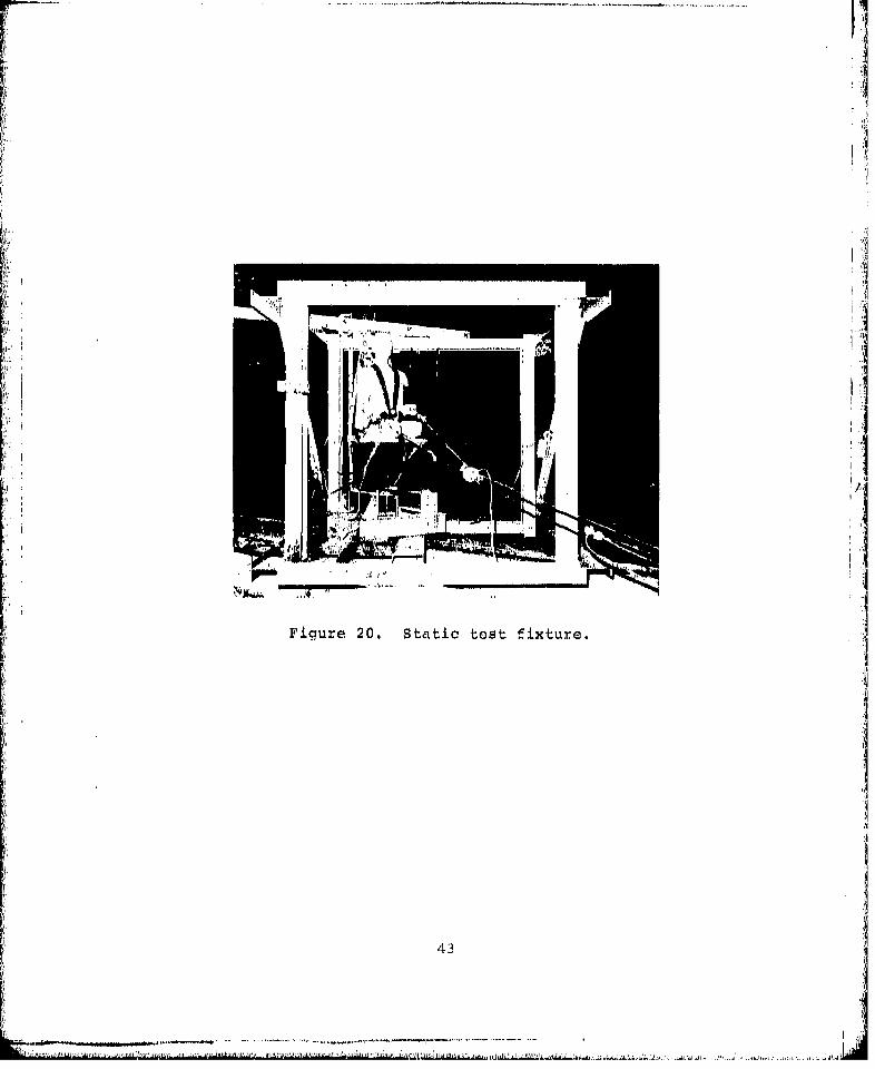
A test fixture was designed and fabricated to support theseat test specimens as they would be supported in the air-craft (Figure 20). The fixture was designed to support theseat under test load application without deflecting. Pro-visions were made for floor attachments and ceiling attach-ments. The floor attachments were mounted on members whichcould be warped to produce a 10-degree pitch on one side anda 10-degree roll on the other side. Standard floor studpans were used at the floor to which the floor quick-disconnectattachments could be connected.
The test fixture was designed to be adaptable for use intesting forward- or aft-facing seats and to orient the seatsfor the various angles of impact force application. Thetest fixture was quickly adaptable to installation of theforward- or aft-facing seats. Force application angles
42
Figur 20.Statc tet fiture
43I
.......
were variable by horizontal rotation of the fixture or by
tilting the complete fixture, or a combination of both.
STATIC TEST REQUIREMENTS
The forward-facing seats were required to be subjected toforward and combined forward, lateral, and vertical loading. [ITests were performed in accordance with the approved testplan (Appendix B). The sixth seat, a forward-facing seat,was tested with successful results in the CH-47C crash testperformed jointly by the Eustis Directorate, NASA-Langley ¶Research Center, and Boeing Vertol (Reference 8).
STATIC TESTS AND DATA ANALYSIS
A total of six static tests were performed using five seats.Four tests were performed using a forward-facing seat con-figuration and two tests were performed using an aft-facingseat configuration. Some retesting was necessitated by com-ponent failures.
Test 1 - Forward-Facing Seat, Forward Load
A forward-facing seat configuration was installed in the test IJfixture, suspended by two wire-bending energy attenuators atthe ceiling and connected by four quick-disconnect studs tothe floor (Figure 21).
The floor studs, mounted in standard recessed floor pans, wereattached to a floor-warping device which was actuated beforetesting (Figure 22). The test fixture was actuated from a
A 95th percentile aluminum body block was installed in theseat and restrained by a four-point lapbelt shoulder harnesssystem (Figure 20). Seat loading was accomplished by attach-ing a cable between the body block and a hydraulic cylinder.The cable was attached to a fitting on the body block at therepresentative center of gravity of a 95th percentile occu-pant. A 50-foot-long cable was used to minimize the loadapplication angle change as the seat stroked vertically(Figure 20). A minimum loading of 15G was to be applied.
Loading was applied gradually iho the body block by the hy-draulic cylinder. Force versus deflection was recorded bythe instrumentation. Excessive deformation began at about60 percent of design load and the curve moved into the un-acceptable base area 9f the Military Specification forcedeflection curve (Figure 25). The excessive deflection wanlattributed to the yielding of the anchor plates attaching
44
................ ...................................

-- *---*---------**---~**-*-
ri4
01
Url
445"
____________________ ----. ,-... ... .... ... ...

I tit'
Figure 23. Floor unwarped.
Figurc' 24. Floor warped.
40
____ . . . . . . . . ....... ..

the seat pan support straps to the seat back and to an under-strength vertical energy attenuator. Failure of the anchorfittings on both sides of the seat occurred at 90 percent ofdesign load (Figure 25).
Stress concentration through the slotted area caused tensileyielding o0: the material adjacent to the slot (Figure 26).Failure of the strap attachment caused the front of the seatpan to drop approximately 20 degrees. Further dropping wasprevented by shoulder straps and the lapbelt attachment tothe seat pan (Figure 27).
The seat was undamaged as a result of the anchor fitting fail-ure. The anchor fittings were replaced with strengthenedparts, and the O0100-in.-diameter wire elements in the verticalattenuators (which had stroked 3.5 in.) were replaced with0.110-in.-diameter wire to increase the stroking load. A retestwas scheduled for the following day.
Test 1A - Forward-Facing Seat, Forward Load
The modified seat was installed in the test fixture in amanner similar to that in Test 1. Load was applied to thebody block by the hydraulic cylinder. Loading was increasedgradually and 135 percent of the design atroking was reached.The force-deflection curve remained inside the boundaries ofthe military vpecification limitations. A failure occurredafter 4.5 in. of longitudinal deformation and was within 8percent of the acceptable failure line (Figure 28).
Failure occurred at the lapbelt attarhment to the side of theseat pan. A long, unsuitable bolt had been substituted forthe original lapbelt attachment bolt to permit installationof a strain-gaged adapter fitting (Figure 29). The adapterwas placed on the threaded portion of the bolt and the boltfailed through the threads. All of the load shifted to theremaining lapbelt side, causing the seat to rack (Figure 30).This caused the diagonal aLtenuator strut to be torn from theseat pan attachment (Figure 31), and cracks to occur in theseat back tubes (Figure 32).
The vertical attenuators stroked 4.3 in. before failureoccurred. No stroking of the diagonal-strut attenuatorswas measured.
Although this test resulted in failure, it was determinedthat the vertical attenuator stroking load was satisfactory,while the diagonal-strut attenuator stroking load should bereduced. Tests were conducted on the struts to verify the1,300-lb. design load and they checked out within tolerance.Stroking load was reduced by diRasserabling the units and
47

•35Ii!
Acceptable failure area30 7 7"/,•> " ' .. ...
Minimnum acceptableload curve
-4040 Fai lure•
U,
0 4 6 810 12
Forward deflection, in.
Pligura 25. Teot 1, forward-ffacing seat, forvarI load/defliction.
48
- ,.. ~|

41)
114T
~(P4
ii\d
. 0......

36~
Acceptable failure area
30
Fai lure
20
'44 0
U
0 2 4 1 n 1Forward~ deflaotilon1 in.
F'igure 28. TIest IA, forward-xVacing snet, forward load/def lection.
Figure 29. Lapbelt~ anchor adapter.
53 o

Fig~ure 30. Post-tes~t racked positior.
Figure 31. Failed atrut aittachmient fittin~g.
j,
Frigure 32. Seat back tube crack. :35 I
Acctblu failro area
3n
20
'i~est stopped404 II101
Forward deflec ion, in.
Figure 33. Test 113, forward-facing seat, forward ioad/de fJIceti On .
52

elongating the holes in the plates which support the trolleyrollers. Offsetting the rollers in this manner reduces thebend angle of the wire as it passes over the rollers. Theload was reduced to 1,100 lb.
Test IS - Forward-FacinnI Seat, Forward Load
A second retest was conducted, using a seat which had beendesignated for aft-facing three-axis combined loading. The,forward -acing test was considered to be more critical thanthe aff acing test because three aft-facing seat tests wereto be performed, compared to only two forward-facing seattests. The n-t was modified to convert it to a forward-facing seat anc to install new vurtical and diagonal-strutenergy attenuators having the revised stroking load valurs.
The modified seat was installed in the test fi,:ture in amanner similar to that in Test 1. Load was applied to thedummy. Some difficulty was experienced with a faulty togglelatch; the latch was replaced and the test continued.
The vertical attenuators began stroking first, as anticipated,duo to the bowstring effect. As the angle of the atten latorEincreased because of seat back movement, the forward load re-quired to cause the vertical attenuators to stroke also in-creased. The forward load increased until the stroking loadthreshold of the diagonal-strut attenuators was reached. Atthis poi ', the seat was in balance and both the upper andlower E-1. nuators were stroking. The force deflection curveproduced the action of the attenuators was within thelimits of Lhe curve upeciiied in the proposed Military Speci-fication, Seat, Helicopter, Troop (Figure 33). The G levelincreased gradually until the seat displaced forward approxi-mately 3 in. At this point, a constant level of 18G wasmaintained as the seat stroked forward the remainder of therequired 10 in., at which point the test was stopped.
The instrumentation recorded loads in the lapbelt, shoulderstraps, and vertical and diagonal energy attenuators and loadapplicator. String potentiometers measured deflections ofthe seat in the vertical and longitudinal directions and wasused along with the applicator load to produce the curve inFigure 33.
Restraint system loads were divided fairly equally betweeneach shoulder strap and each side of the lapbelt (Figure 34).Data on the shoulder strap load was lost at the 1300-lb level.Load da+a on the vertical attenuators was not reliable dueto bending of the fittings to which the strain gages wereattached. DLagonara-strut attenuators were designed to strokeat 1100 lb. The instrumentation data showed the load to rise
53
... .. .. .. .. A j . ~ I P

4,800
4,000
3,200 -- _ _ _ _ _ _ _
2,400 ..p "
O O,
1,600 - _ , ,
/ 9
B00 / eft lapbelt - -
---- Right lapbeltT -- -Left shoulder strap
Right sholdr sraRight lapbelt (strain gage)
0400 800 1,200 1,600 2,000 2,400
Strap tension, lb
Figure 34. Test 13, lapbelt and shouldor strap loads.
54
•,,• ".. ... 'j•.L ,! ..'' ' ' * ..... . . .. .. .. ... ..... All,•-- Lý' 10.. ... , • ,

Knto approximately that level, at which point the attenuatorsbegan stroking. This relieved the load on the hydraulicactuator and momentarily caused the load curve to drop, pro-ducing a false reading which would not exist under a dynamicsituation.
After the test, a visual inspection of the seat was made.There were no failures of the seat structure or fabric(Figure 35). Some deformation was observed in the seat panside tubes which had bowed up 0.5 in. in the center (Figure36). The vertical attenuators were found to have stroked6.75 in. (Figure 37) and the diagonal-strut attenuatorsstroked 3.62 in. (Figure 38).The test conclusions are that the results were highly success-ful in meeting all tast objectives.
Test 2 - Forward Load on Aft-Facing Seat
An aft-fac...ng seat configuration was installed in the testfixture, suspended by the two wire-bending attenuators at theceiling and connected to the floor quick-disconnect studs atfour places (Figure 39). The test fixture had been rotated180 degrees from the Test 1 position. The diagonal-strutattenuators had been reworked to reduce the stroking loadto 1,000 lb, 100 lb below the attenuators used in Test lB.
A 95th percentile aluminum body block was installed in theseat and restrained by a four-point lapbelt shoulder harnesssystem (Figure 39). The restraint system was not instrumentedbecause the loading was toward the seat back and the restaintsystem received no load. Seat loading was accomplished byattaching a cable between the body block and a hydrauliccylinder. The load was applied effectively through thecenter of gravity of the body block by using a cable loopattached to fittings at each side of the body block (Figure39). A minimum loading of 15G was to be applied.
Loading was applied gradually to the body block by the hydrau-lic cylinder. Force versus deflection was recorded by theinstrumentation. Initial application of the load caused theseat to deflect backwards with little resistance, because theattachment of the toggle latch to the ceiling was at the sameangle with the back as for forward-facing seats. This deflec-tion caused an intruision into the base area of the forcedeflection curve (Figure 40). As the angle of the togglelatch reversed, seat deflection decreased until a lOG forcewas applied, raising the curve out of the base area.
55
.... .......
05

AA
Figure 37, stroked diagonal attenuators.
571
.. ...... .

F-w
Figure 39. Pro-test aft-facing seat., back loading.
Ai
i 58 -
I I|•,- --''
40
35
Acceptable failure area30"
I 30 Minimum acceptable•" load curve
020 stopped •!
10
02 4 6 8 10 12
Backward deflection, in.
Figure 40. Test 2, aft-facing scat, backward load/doflection.
59
.. ......... .

-------------
The initial deflection due to toggle-latch reversal also causedthe angle of the diagonal attenuator strut to decrease in rela-tion to the floor. The reduced angle, and the fact that theattenuator stroking load had been reduced below that of theTest lB attenuators, caused premature stroking. This againcaused a second slight intrusion into the base area to theextent of approximately 2G (Figure 40). The force/deflectioncurve soon rose out of the base area and above the minimumfailure area line. The test was stopped when 11 in. of deflec-tion had occurred.
An inspection of the seat was made after the test. No struc-tural or fabric failures were found (Figure 41). Upper atten-uators were found to have stroked 7 in. (Figure 42), and thediagonal-strut attenuator stroked 6.4 in. (Figure 43).
The teat conclusions are that the results were satisfactory.Improvements can be achieved by relocating the upper seatattachments for aft-facing seats to reduce the initial de-flection. In addition, the diagonal-strut stroking loadshould be maintained at the same level as that used in TestlB. This will raise the load deflection curve sufficientlyto prevent intrusion of the base area.
Test 3 - Aft-Facing Seats, Lateral Load
An aft-facing seat configuration was installed in the testfixture, oriented 90 degrees to the pull force. The seat wassuspended from the ceiling support beam by two wire-bendingattenuators and was connected to the floor quick-disconnectstuds at four places (Figure 44). The load was transferredthrough the body block to the restraint system attached atthe side of the seat and at the top of the seat back. A mini-mum loading of lOG was to be applied.
Loading was applied gradually by the hydraulic cylinder. Forceversus deflection was recorded by the instrumentation. Theforce was increased until 86 percent of the design strokingload waa reachad. At this point, ehc we'lded connection ofthe tubing at the front corner of the seat pan failed (Figures45 and 46). A soft weldable aluminum alloy tubing had beenused in the construction of the seat pan, which contributedto the failure and allowed deformation of the seat, causingsome intrusion into the base curve area (Figure 47).
The production version of the seat described in Reference 5uses high-strength aluminum tubing and a forged aluminum cornerfitting which is mechanically fastened. Such constructionwould be more rigid than the test model and would withstandhigher loads. The intrusion of the force deflection curveinto the base area close to the base curve and the occurrenceof failure at 86 percent of design stroking load indicates
60
.... .. ,, , . . . . .. . . . . .[

1k0 .

.......... I
Figura 42. Stroked vertical. attenuatorg.j
F i-uro 43.* Strokeid di~acqollI ittonuators.
.........
4.J
r)
-44
fie,~
ww
544
t- 0)
S.. ........ ,
V i c l r c, 6 I ' l l o d Fl e a , p a c o n c i r

I
23 Acceptab].A failureQ area
S20 "Minimum acceptablego •• ., ~load ourvel.';
0
1-4Rejection area
ý4)4
ii 10 S1 Base curvo
S2 4
Lateral deflection, in.
PFigure 47. Test 3, aft-facing seat, lateral load/deflection.
6I5
.. .... ..

that a small increase in stiffness and strength would put thefor,.e deflection curve into the acceptable area.
The instrumentation recorded lateral and vertical deflectionsof 2.5 in. at the time of failure. The excessive vertical de-flection was due to yielding of the soft seat pan tube at thepoint where the deflection potentiometer was attached. Measure-ment of the vertical energy attenuators showed them to havestroked 0.5 in. The front diagonal cable had stroked 0.75 in.and the rear diagonal cable 1.2 in. Strain gage data from the iattenuators was not reliable. Instrumentation data on lapbeltand shoulder harness loads shows a maximum of 1,050 lb on thelapbelt and 1,550 lb on the loaded left shoulder strap (Figure48).
The test conclusions are that with minor improvements, the ueat.will meet the requirements for lateral loading. The seat re-mained stable during the loading sequence. There was no ten-dency for the seat to rotate or twist. All attenuators req.ired.to stroke were stroking at the time of failure. The forcedeflection curve and load at the time of failure weresufficiently close to the test objectives so that a slightincrease in seat pan rigidity and strength will allow theseobjectives to be met.
Test 4 - Porward-FacingSeat, Combined Loading
A forward-facing seat was installed in the test fixture whichwas pitched up and yawed to simulate a three-axis crash loadcondition (Figure 49). The minimum loading to be applied was14.5G downward, 15G forward, and 9G lateral. The seat wasattached to the test fixture in the same manner as previoustests.
A 95th percentile aluminum body block was placed in the seatand restrained by a four-point lapbelt shoulder harness system.The seat wan loaded by applying a load to the body block througha looped cable attached to fittings on each side of the bodyblock (Figure 49). A resultant of the forward, lateral, anddown loads was applied through the center of gravIty of the..body block. A minimum loading of 5,000 lb was to be applied.
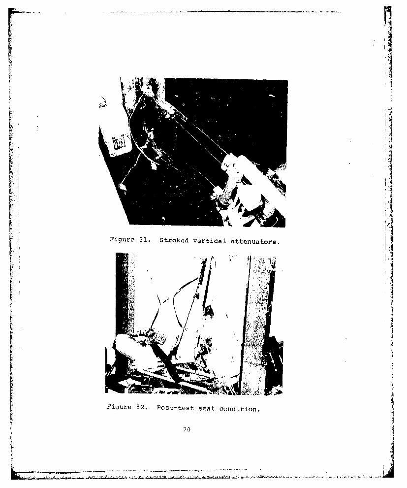
Loading was applied gradually by a hydraulic cylinder. Forceversus deflection was recorded by the instrumentation (Figure50). The minimum design load was reached at 5 in. of forwarddeflection. The load continued to climb to 6,200 lb when thetest was stopped at the point of 10 in. of deflection alongthe load axis. Most of the deflection was a result of thevertical attenuator stroking (Figure 51) and rotation of thediagonal-strut attenuators (Figure 52). The seat moved down-ward 6.3 in., forward 9 in., and laterally 4 in, Strain-gaged
60

Left lapbelt
2,400:'; ,',RighL Iapbelt (strain gage)
Right lapbeIt
j/ (tensiometer)
2,000 t.. .. .
,00,
2,0 -L-tsoud/ ta
1,00t
S400o _ _____
,4W
0 400 800 1,200 1,600 2,000
Strap tension, ll.;
FigtUre 4F . I apbo-iJt aInIdI slouldu'r ;;L• r-p.
--..- , -.,-

.. ... .. ...
a
low
Viqure 49. Prrc- tcst for'wtrcl-fzacini. scait:, Combine~dthroo-axis l~oading.3
(. il
6,000 -
minimum required load5,000 -
J
S 4,000
0
_H
II 3,000-
+U k '•
1<,000
0 2 4 6 810
Forward deflection, in.
Figure 50. Forward-facing seat, combined triaxial loading,forward deflection.
69
....
° !
Fiue5 Srkdvertical, attenuators.I
Figure 52. POst-test seat condition.
'70
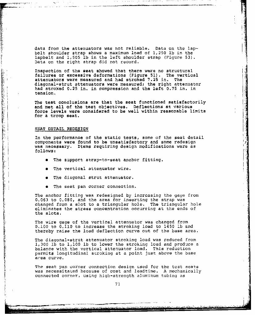
data from the attenuators was not reliable. Data on the lap-belt shoulder strap shows a maximum load of 1,250 lb in thelapbelt and 1,505 lb in the left shoulder strap (Figure 53).Data on the right strap did not record.
Inspection of the seat showed that there were no structuralfailures or excessive deformations (Figure 51). The verticalattenuators were measured and had stroked 7.25 in. Thediagonal-strut attenuators were measuredl the right attenuatorhad stroked 0.25 in. in compression and the left 0.75 in. intension.
The test conclusions are that the seat functioned satisfactorilyand met all of the test objectives. Deflections at variousforce levels were considered to be well within reasonable limitsfor a troop seat.
SEAT DETAIL REDESIGN
In the performance of the static tests, some of the seat detailcomponents were found to be unsatisfactory and some redesignwas necessary. Items requiring design modifications were asfollows:
* The support strap-to-seat anchor fitting.
a The vertical attenuator wire.
e The diagonal strut attenuator.
a The seat pan corner connection.
The anchor fitting was redesigned by increasing the gage from0.063 to 0.080, and the area for inserting the strap waschanged from a slot to a triangular hole. The triangular holeeliminates the stress concentration occurring at the ends ofthe slots.
The wire gage of the vertical attenuator was changed from0.100 to 0.110 to increase the stroking load to 1450 lb andthereby raise the load deflection curve out of the base area.
The diagonal-strut attenuator stroking load was reduced from1,300 lb to 1,100 lb to lower the stroking load and produce abalance with the vertical attenuator load. This reductionpermits longitudinal stroking at a point just above the basear'ea curve.
The seat pan corner connection design used for the test seatswas necessitaLed because of cost and leadtime. A mechanicallyconnected corner, using high-strength aluminum tubing as
71
S~~~~~~..... .... ............ .----..- .--.-. -.. ... ,,.. .

4,000Right lapbelt
(strain gage)
Left shoulderr
Left lapbelt
H1,600
800
0 400 800 1,200 1,600
Strap tension, lb
FUigure 53. Laipbelt and shoulder strap loads.
72
designed for the production version of the seat, is the pre-ferred method. However, time and budget did not permit use ofthis design on the test articles, and a welded joint wasemployed, using softer weldable tubing. Design modificationsfor the seats to be dynamic-tested consisted of the additionof 0.125-in.-thick alumi.num straps added to the inside anndoutside of the seat pan cotrners.
TASK 11I SUMMARY"•:[
Analysis of the static test. data shows that the seat functioned.properly in the direction of the predominant impact attitudesunder forward and combined vertical, forward, and lateral load-ings. Difficulty was experienced with the pure lateral loadcondition, missing the test objectives by a small margin. Re-placement of the soft weldable tubing with a higher-strengthtubing and the use of a mechanical joint at the corner of theseat pan would provide the adequate strength and rigidityneeded to meet the test objectives. Such a design was pre-sented in Reference 5 for a production vers-i.on of the seait,but a long leadtime was needed and the cost of the cornerfitting forging used was too expensive in small quantities "1for the test articles.
In the aft-facing seat test, some minor intrusion of the force 'c,deflection curve into the base area was experienced. 1owever,a minor intrusion into the base, area is not as critical for atroop seat as it is for a pilot seat. A pilot is limited inforward stroking, due to the necessity for clearance from thecontrol nolumn and instrument panel. Troop seat installati-onsgenerally have more forward clearance with hard structure thanpilot seats. When this is the case intrusion into the baseIarea is acceptable as long as the energy represented by thearea of the intrusion is accounted for by additJonal stroki.tIg.Additional stroking allowances have already been made ii thedraft Military Specification, Seat, He.itcopter, Troop, to id ].owfor the higher flexibility of a troop seat and L:o pormL11[t So)meintrusion into the base area.
The results of the static test indicate Lhat with khe minorYmodifications of the attenuator load settings, and with re-designed strap anchor fittings installed on the seat, thecrashworthy troop seat test articles will function as requ iredin a crash environment. The static test and analysis showthat the seats were ready for verification of thcir crash-worthiness functions by dynamic testing.
. .. .. . . ..... . . . .. . . ... . .. . . .. .. . . .... ie ]01 .... ...
CRASHWORTHY TROOP SEAT TESTING - TASK III
TASK III REQUIREMENTS
Dynamic testing of a minimum of two aft-facing and two for ward-facing seats was required. The required effort under Task IIIwas as follows:
a The fabrication, modification, and assembly of forward-and aft-facing seat systems, in accordance with theapproved detail design developed in Task I and the re-finements determined to be necessary as a result ofTask II static testing.
* The preparation of seat system and test fixtures toperform dynamic testing in accordanne with the approveddynamic test plan (Appendix C).
* The performance of dynamic tests on seat systems inaccordance with the approved dynamic test plan.
e The analysis of data obtained in dynamic tests for thepurpose of verifying the adequacy and feasibility ofthe design criteria contained in the proposed MilitarySpecification; Seat, Helicopter, Troop, and Chapters 3and 4 of Reference 9. Those requirements and/orcriteria that were insufficient to insure troop seatoccupant protection throughout the 95th percentilesurvivable accident were to be identified, as well asthose requirements and/or criteria that exceed thestrength or performance criteria necessary to providetroop seat occupant protection during the 95th per-centile survivable aircraft accident, or which,because of practical considerations, are proven toostringent to be feasibly met by curient technology.
* Criteria and requirements contained in the proposedMilitary Specification; Seat, Helicopter, Troop, andReference 9 were to be substantiated, or changesshall be reconunended.
Each of those areas is discussed in this report in the orderlisted above.
9 CRASH SURVIVAL DESIGN GUIDE, Dynamic Scionce; USAAMRDL Tech-nical Report 71-22, Flushis Directorate, U. S. Army AirMobility Research and Deelopment Laboratory, "ort EustJis,Virginia, October 1.971, AD '733358.
74
~ u~I~i ~ AL4 tAM~L..UL.W ~ ,.A~ ~ ai. ~ z1,~,4 ,V. Ur~Ah~z44I~.

u FABRICATION ANO MODIFICATION OF SEAT SYSTEMS
As a result of static testing, the four remaining seats weremodified to eliminate the deficiencies found during Task II.The following modifications were made:
1. Replace the vertical wire-bending attenuators, usinglarger diameter wire for a higher load setting of1,450 lb each.
2. Rework the diagonal tubular wire-bending attenuatorsto reduce the load setting to 1,100 lb each.
3. Reinforce -the seat pan front corners.
4. Replace the anchor fittings for attachment of theseat pan support strap to the seat back.
5. Reinforce the hinge fittings for attachment of thediagonal-strut attenuator to the seat pan.
These modifications were accomplished and the seats werereadied for dynamic testing. Strain gages were added to thediagonal energy-attenuating cable fork fittings, and to therod end fittings at the end of thp tubular attenuators.
DYNAMIC TEST PREPARATION.
Dynamic tests were performed at the FAA Civil AeromedicalInstitute (CAMI), Oklahoma City, Oklahoma. A horizontal trackwas used to simulate both horizontal and vertical crash impacts.The CAMI test track is an impact test device capable of pro-ducing a controlled deceleration pulse variable from 0.4 to60 G's. The device consists of a wheeled test sled whichmoves along two horizontal rails, an accelerating device, anda sled braking device. The sled is a flat topped vehicle uponwhich the test specimen is mounted. By use of adapters thetest specimen can be mounted in a variety of orientationsrelative to the impact force vector.
Sled velocity is provided by a Newtonian acceleration systemconnected through a cable to the sled. This system acceler-ates the sled at a constant G level to the desired impactvelocity over a maximum distance of 68 feet. The sled thencoasts freely for 10 feet and is then decelerated by a metaldeforming brake system. The deceleration force is producedwhen the sled contacts wires which pass over the rails andthrough brake units on either side of the rails. As thewires pass through the brake units, they are plastically de-formed by being bent over a series of rollers. This plasticdeformation produces a tension force in each wire which istransmitted to the sled. Wire size and the deforming bends
75
which it undergoes were selected to generate a nominal 2500lb force to extend each wire. The braking system accommodatesa total of 20 wires, providing an impact force capability of50,000 lb.
The sled deceleration time history is controlled over a widerange of onset rates, G levels, and stopping by selection ofthe number and location of the decelerating wires in conjunc-tion with control of sled velocity and weight.
Deceleration onset rate can be controlled for 22 feet of brak-ing distance. Total braking distance may be varied from 4inches to 22 feet, depending on sled velocity and G level.Sled maximum velocity for a 300-lb test specimen is 70 feetper second and for a 2,500-lb test specimen is 45 feet persecond.
To simulate vertical impacts, the test fixture was preparedto support the seat with a simulated floor and ceiling. Theseat was oriented for impact with 30-degree pitch and 10-degreeroll, to provide a force with combined vertical, horizontal,and lateral components (Appendix C). The fixture was thenrotated backwards 90 degrees and placed on the horizontallymoving sled.
A similar fixture was used for horizontal impacts with alateral componnnt. The fixture was mounted upright andpositioned at a 30-degree yaw angle.
The sled was accelerated, through a series of cables andpulleys, by a lead weight which fell into a container of sand.Elevation of the weight was accomplished by pulling the sledback along the track to a latch mechanism, which was releasedat the time of the test.
Electronic Instrumentation
The electronic instrumentation system of the CAMI test trackis designed for maximum versatility and reliability under thedeceleration forces encountered during impact tests. Specialprovisions have been made for the use of bridge type trans-ducers. This type transducer has proven to be useful andreliable for measuring strain, acceleration, pressure, forceloading and low frequency vibrations.
Signals are transmitted from sled-borne transducers to track-side signal conditioners through an umbilical cable attachedat one end of the sled and which travels with the sled as itmoves down the track. These signal conditions provide excita-tion to the transducers (3-10 Vdc) , amplify the signal, allowlow-pass filtering when desired and provide a resistance shuntcalibration for each transducer through the entire data
76
S--~'-- '~.. .... ....... ... ...... .
recording system. Filter classes used during the tests areshown in Table 1.
Outputs from the signal conditioners modulate subcarrier oscil-lators of a high-frequency constant band width multiplexersystem. The composite output from the multiplexer system isrecorded on wide band magnetic tape, The magnetic tape isreproduced through appropriate discriminators and displayedon an oscillograph recorder for quick look analysis. Asrequired, portions of these data are then reproduced from themagnetic tape-discriminator combination into a high-speedmulti-channel analog to digital converter system and placedin a computer compatible form on high density digital tape.Routine reduction of the impact data provides tabular outputand scaled plots versus time of acceleration, vector sumacceleration, velocity and displacement for further analysis.
Impact Force Process
The impact process is composed of two basic assembly languageroutines, one COBOL program and one FORTRAN program, TheForce/load process is made up of the same basic and COBOL pro-grams plus a separate FORTRAN program. The processes are runseparately, depending on the type of input received, and arecapable of handling multiple reels of input. The processesperform the following data handling and computational functionsi
1. Converts the binary code from the analog to digitalequipment to an IBM code.
2. Calibrates the data based on the mean of the highand low calibration records.
3. Converts the digitizer counts to G's.
4. Selects the starting point on the data tape by finding
the two steps in the velocity channel.
5. Digitally filters the selected channels of data.
6. Applies a five point moving average smoothing processto the selected data channels.
7. Computes the vector sum of the X, Y, and Z datachannels.
8. Determines maximum values and their time of occurrence.
9. Computes the first integral (velocity) of carriage Zdata.
77
/-... ..' ........ V I.lk

TABLE 1. INSTRUMENTATION
Fi terTest Data Type Range class
Series 1 Chest CEC 250 0 180 DSeries 2 Pelvis CEC 250 G 180 D 1'y
Floor CEC 250 G 60 DPan Entran 100 G 60 DBelts Lebow 3500 lb 4KHz AStrains Custom Custom 4IHz A
Series 3 Cheat CEC 100 a 180 A "Pelvis Entran 100 G 180 AFloor CEC 250 0 60 A
Belts Lebow 3500 lb 4KHz AStrains Custom Custom 4XHz A
NOTES:
CEC - 4-202-0001
Entran - EGA-160F-10OD-SL
Lebow - 3419
Custom - supplied with seat
Filter class is to SAE-&211b analog or ditigal asindicated.
78

10. Computes the second integral (displacement) ofcarriage Z data.
11. Builds a graph tape with control information valuesto produce point plots.
DYNAMIC TESTING
Test Requirements
All tests were to be performed in accordance with the dynamictest plan (Appendix C). The test requirement for a forward-facing seat was a combined downward, forward, and lateralloading, with an impact at 50 fps and a pulse peak of 48 G.In addition, a forward-facing seat was to be tested in a for-ward direction with a lateral component. Impact velocity wasto be 50 fps with a pulse peak of 24 G,
An aft-facing seat was to be tested fur combined downward,backward, and lateral loading, with impact at 50 fps and apulse peak of 48 G. Also, an aft-facing seat was to be testedin a backward direction with a lateral component. Impactvelocity was to be 50 fps with a pulse peak of 24 G.
Test 1 - Forward-Facing Seat, Three-Axis Loading
A forward-facing seat was installed in the dynamic test fix-ture and a 95th percentile dummy with equipment, weighing a1total of 243 lb, was strapped into the seat (FiLgure 54). Theseat was oriented to simulate 30-degree pitch down and 10-degree roll. The sled was accelerated horizontally to simu-late a vertical drop and impacted the barrier at 49.34 fps.
A visual inspection of the seat after the test revealed noseat structure or fabric failures (Figure 55). Both verticalattenuators had stroked 1.0.75 in. The right diagonal-struttubular attenuator was found to have a dent in it rosultinqfrom striking a bolt head on the floor. This indicated thatthe seat had bottomed out on the floor.
The input pulse to the seat was recorded by accelerometersinstalled on the sled. As the sled impacted the barrier anddecelerated, the deceleration level was measured in thedirection of impact. Accelerometers on the sled measuredthe force in G while a timing device measured the sled velocityat the time of impact. The G force w:-is plotted with respectto time (Figure 56). A time base of .063 second and a velocityof 49.34 fps were recorded, both ronsonably close to the speoc-fied .065 second and 50 fps velocity. A peak (I value of 4B (was specified, however, this ts a theoret:lca] value. Only tjhemaximum G, which was 45 (1, Is recorded and p lotLed, whil, i he,
7 ')

4. Li r o L os It; c.-) - a hi~~ s Loidnq,1
iti
I A
II ...........
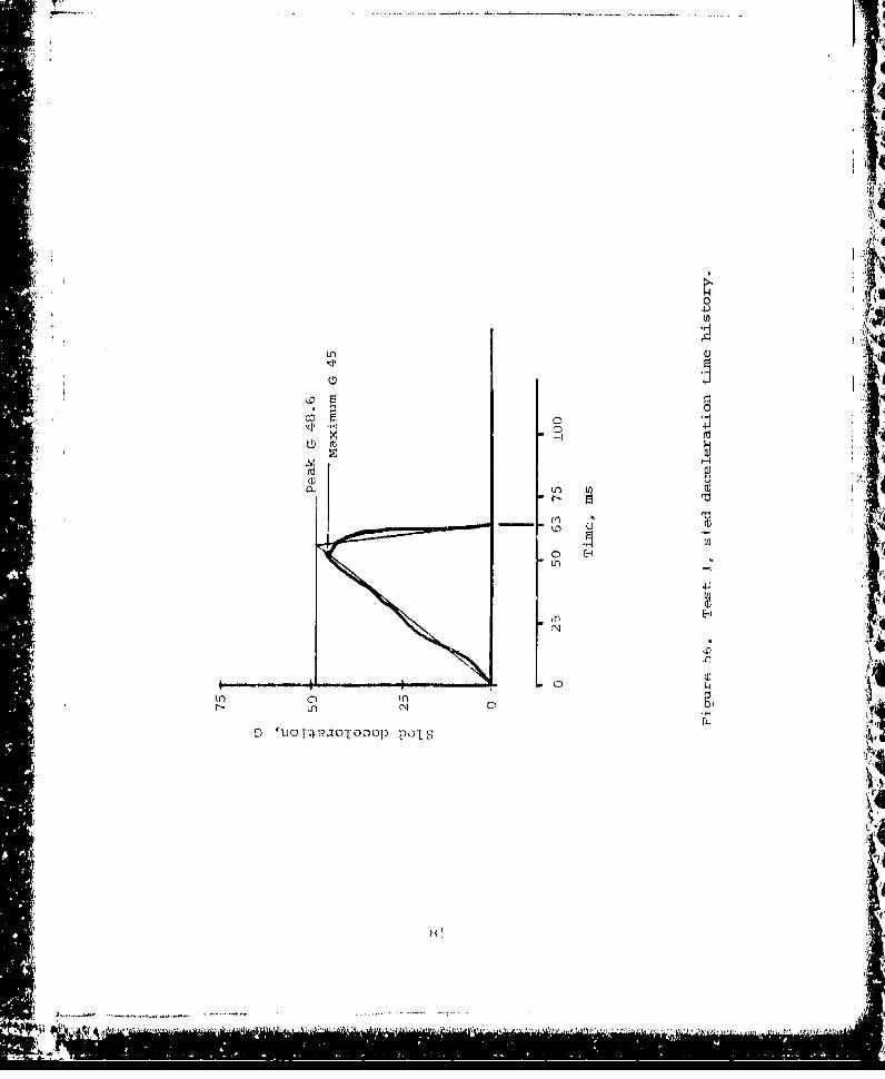
4J'
LAn
'4JV)
LnIU) l

peak 0 must be calculated. Knowing the velocity and the timebase, which are recorded by instrumentation, the theoretical"peak G can be determined as follows:
32.2 G 2 V- • pkt
Th, peak G is pG 48.64 Hi pk
The peak G is superimposed over the recorded pulse data (Figurep 56).
Instrumentation data showed that ý,aximum loads and attenuatorstrokes recorded were as follows:.
Instrumented Item Maximum Load-Lb Stroke-In.
Right lapbelt 400Left lapbelt 400Right shoulder strap 700Left shoulder strap 400Front diagonal cable 0 0Rear diagonal cable 0 0Right diagonal strut 400 0Left diagonal strut 500 0Right ceiling attenuator - 10.8Left ceiling attenuator - 10.8
An analysis of instrumentation data verified that there wasresidual energy in the seat at the time the seat reached max-imum stroking distance. Although the seat is theoreticallycapable of stroking 14.5 in., downward deflection of the frontof the seat pan contributed to premature bottoming of theseat. Deflection was a result of seat pan support webbingstretch. However, had the full 14.5-in. stroke been used,there would have been excessive energy left, as shown by thepeak of 67 G in the vertical direction registered on thepelvis when the seat bottomed (Figure 57). An initial over-shoot condition is shown in Figure 57 with the accelerationon the dummy rising to 21 G. This condition is attributedprimarily to two factors. First is the characteristic higherinitial force required to start attenuator stroking andsecondly is the manner in which the seat was tested. Verticalimpact was stimulated by laying the seat back and porformingthe test on a horizontal track. The initial 1. (1 force of thedummy against the seat pan was not; present and addit iona]acce.ieratior of the dummy into the seat pan resulted at impac .
The horizontlal test (Test. 3A which will be discussed lato'-)was conducted in a normal, attitude and no overshoot condditifolwas recordod on the lvis.
02*1 ]*i
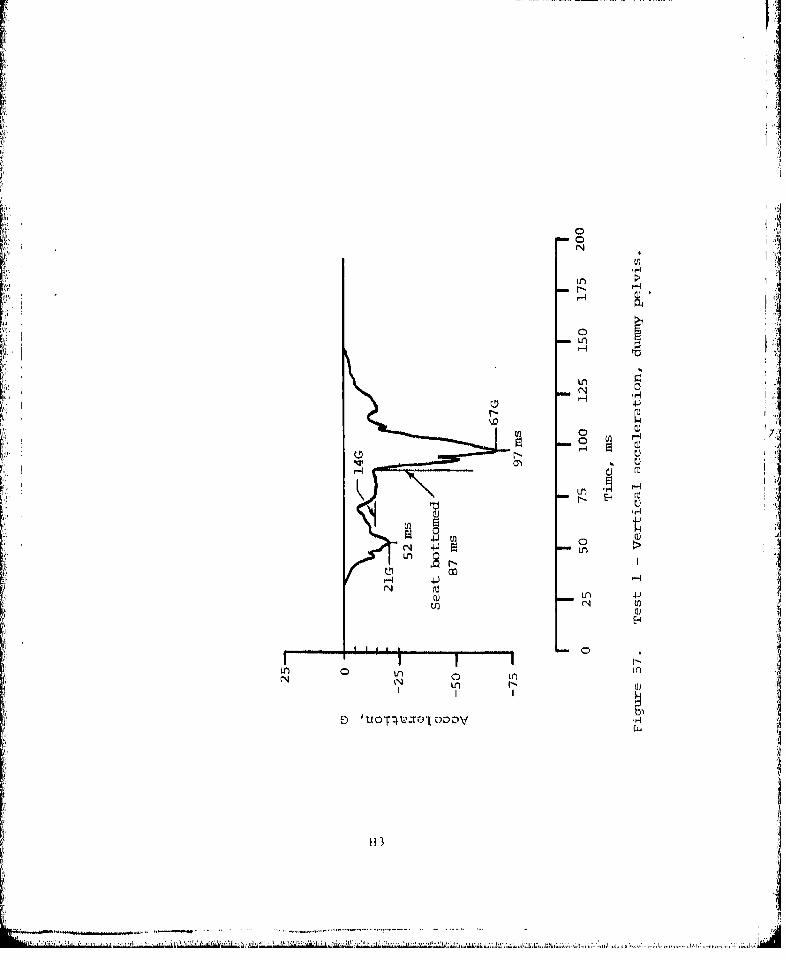
0F
0 1
InIUl
LnIN 'uorLo~t~i
II, _ _ _ _ _ _ _ _ _ _ _ _ I4I
ITJ I~ -. 4-J
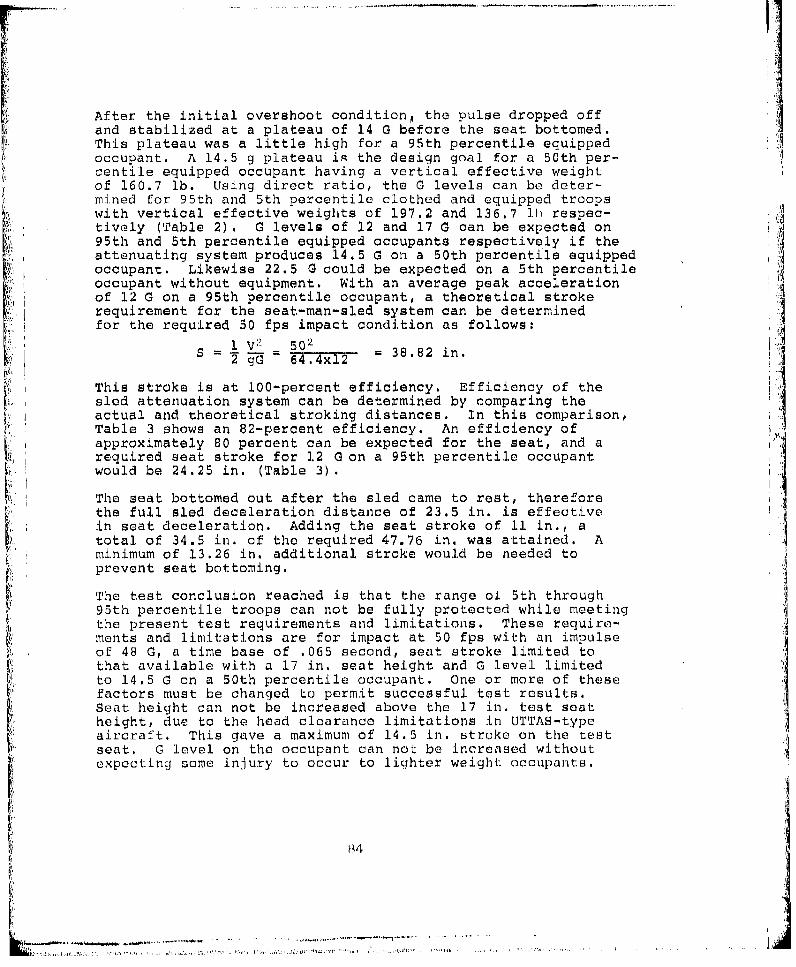
:~ ................
After the initial overshoot conditiong the pulse dropped offand stabilized at a plateau of 14 G before the seat bottomed.This plateau was a little high for a 95th percentile equippedoccupant. A 14.5 g plateau is the design goal for a 50th per-centile equipped occupant having a vertical effective weightof 160.7 lb. Using direct ratio, the G levels can be deter-mined for 95th and 5th percentile clothed and equipped troopswith vertical effective weights of 197.2 and 136.7 lb respec-
V tively (Table 2) . G levels of 12 and 17 G can be expected on95th and 5th percentile equipped occupants respectively if theattenuating system produces 14.5 G on a 50th percentile equipped•i'i•occupant. Likewise 22.5 G could be expected on a 5th percentileoccupant without equipment. With an average peak acceleration
Sof 12 G on a 95th percentile occupant, a theoretical stroke :irequirement for the seat-man-sled system can be determined
for the required 50 fps impact condition as follows:
V2 502 IS = 64=4x12 = 38.82 in.
This stroke is at 100-percent efficiency. Efficiency of thesled attenuation system can be determined by comparing theactual and theoretical stroking distances. In this comparison,Table 3 shows an 82-percent efficiency. An efficiency ofapproximately 80 percent can be expected for the seat, and a
rip required seat stroke for 12 G on a 95th percentile occupantwould be 24.25 in. (Table 3).
The seat bottomed out after the sled came to rest, thereforethe full sled deceleration distance of 23.5 in. is effective,,',.in seat deceleration. Adding the seat stroke of 11 in., a
total of 34.5 in. of the required 47.76 in. was attained. Aminimum of 13.26 in. additional stroke would be needed toprevent seat bottoming.
The test conclusion reached is that the range ol 5th through95th percentile troops can not be fully protected while meetingthe present test requirements and limitations. These require-ments and limitations are for impact at 50 fps with an impulseof 48 G, a time base of .065 second, seat stroke limited tothat available with a 17 in. seat height and G level limitedto 14.5 G on a 50th percentile occupant. One or more of thesefactors must be changed to permit successful test results.Seat height can not be increased above the 17 in. test seatheight, due to the head clearance limitations in UTTAS-type,aircraft. This gave a maximum of 14.5 in. stroke on the testseat. G level on the occupant can noI be increased withoutexpecting some injury to occur to lighter weight occupants.
-R4
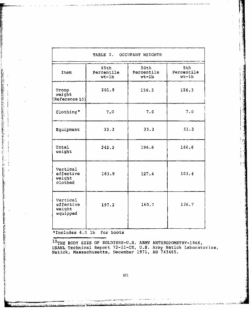
TABLE 2. OCCUPANT WEIGHTS
95th 50th 5thItem Percentile Percentile Percentile
wt-lb wt-lb wt-lb
Troop 201.9 156.3 126.3weJght
(Reference 10)
Clothing* 7.0 7.0 7.0 o
Equipment 33. 3 33.3 33.3 :
Total 242.2 196.6 166.6weight
Verticaleffective 163.9 127.4 103.4weightclothed
Verticaleffective 197.2 160.7 136.7weightequipped
*Includes 4.0 lb for boots
1 0 THE BODY SIZE OF SOLDIERS-U.S. ARMY ANTHROPOMETRY-1966,USANL Technical Report 72-51-.CE, U.S. Army Natick Laboratories,Natick, Massachusetts, December 1971, AD 743465.
85
7 7. 7 . 1. . , . • r ,, , . , ,. . .. ,. . . q•. , : ,, Ll ,' ,,.• ,• ' . . I , • ,, ": :: h • ': '• .• • -•.:,• ."• : '• • !'•• • '{=
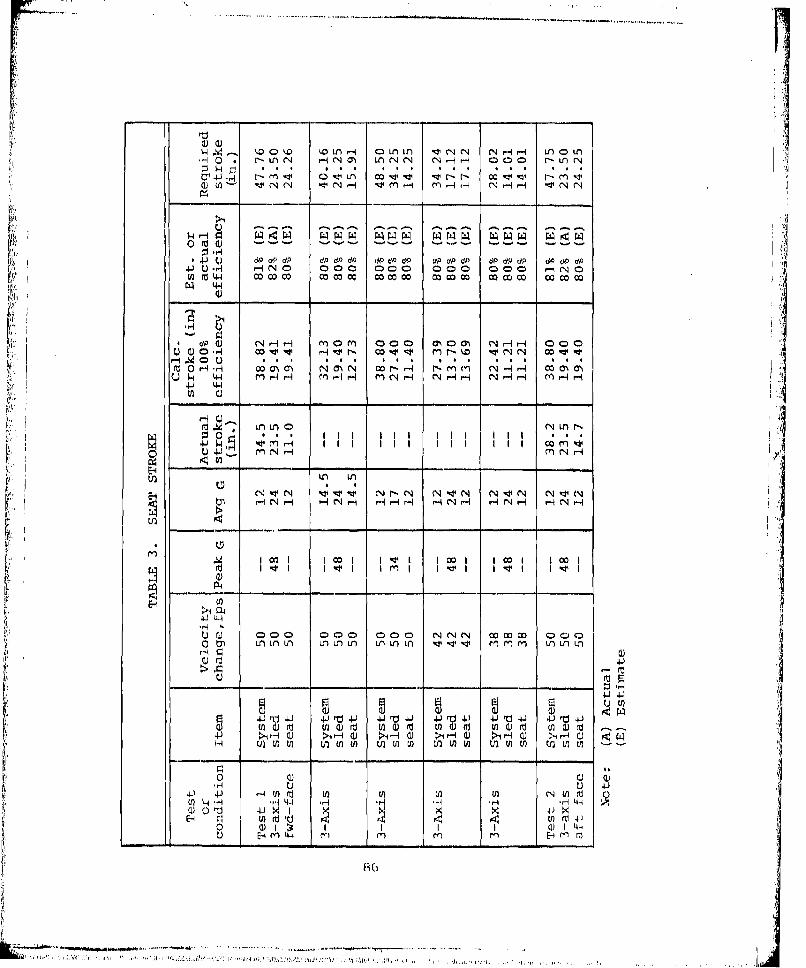
w 4.i 1.0 k ýD '.LM. OLfl) i c'e' 1 N N -I r- LflO0Lflr- * r N-f N 0r'O' LfCNCN C4 N 1--i co00 U ~LlN
4JU r- - 000 r oI~ 1 1r 0G0 000 000 -UNO t~
I0) Ln w -4N H( -
4-* H -4 0 C)a 00 0 00 a Q ) 0 r- NH 00
dOH N racI rr-- 0 m coo N 0 N -4 H cooa
.' 001 Ho- 4 r VNNoDq (" n-0
fu~ r~ 0 75 -H0I)mNC 0 -r 1
4.J 44
m. i.w 000 000 00 NN'c Lr 000 0
q W WU.Jr UVWr
V) ' H t L ý W t
N 11 V Nr N N4;PN N-4 N 4
N - P4N - ýri - NPi - N H H -
LOi

Ii
A reduction of the impulse requirement is the least complexsolution. This can be accomplished by reducing the impactvelocity or by reducing the impulse to the seat by relying onthe aircraft to absorb more of the energy. Newly requiredenergy absorbing landing gear will permit the aircraft toabsorb more energy. If the requirement for 50 fps impactvelocity is maintained, the peak G to the seat must be reducedfrom 48 to 34 G. This is necessary while limiting G level onthe 95th percentile equipped occupant to 12 G and limitingseat stroke to the available 14.5 in. (Table 3). Reductionof the impact velocity to 38 fps would be required if additionalenergy could not be absorbed by the aircraft. This is themaximum velocity that can be tolerated if G level on the 95thpercentile occupant is limited to 12 G and seat stroke is
limited to 14.5 in. (Table 3). A higher impact velocity ora higher peak G could be tolerated, without the seat bottoming,with an equipped 95th percentile troop, or. without the non-equipped 5th percentile troop exceeding 23 g, if the 50thpercentile occupant acceleration were raised from 14.5 to 16 g
Test 2 - Aft-Facing Seat, Three-Axis Loading
An aft-facing seat was installed in the test fixture and a95th percentile dummy without combat pack weighing 220 lb wasstrapped into the seat face down (Figure 58). The seat waspitched back 30 degrees and rolled 10 degrees. The sled wasaccelerated horizontally to simulate a vertical drop, and im-
pacted the barrier at 49.44 fps.
A visuaL inspection of the seat after the test revealed nostructure or fabric failures (Figure 59). Both verticalattenuators had stroked 14.87 in. (Figure 60). The diagonal-strut attenuators stroked 0.3 in. in tension (Figure 61).There was no physical evidence of the seat having bottomed out,but tho length of the stroked vertical attenuators indicatedthat bottoming must have occurred.
Instrumentation data showed that the maximum loads and atton-uator strokes recorded were as follows:
Instrimiented Maximum load-lb Stroke-in.
Right lapbolt 400Left lapbelt 400Right shoulder strap 80Left shoulder strap 80Front diagonal cable - 0Roar diagonal cable 250 0R:I ght diagonal strut 1000 . ]Left diagonal sLrut 1100 .2RicjhLt coeilinc attenuator - 14.')Left coi.l ri g attenuator 14.(
B{ 7

FLu r c) B ]re-tes L 2 1. o]hr~ nx nd i n c
A4,,
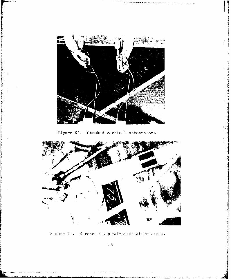
AJ.
Analysis of instrumentation data showed that the seat bottomedout at 98 milliseconds (Figure 62). An overshoot reaching 78 Goccurred. Before bottoming, an initial overshoot occurred whichreached 24 G. This overshoot can be attributed to severalfactors. One is the characteristic higher initial forcerequired to start attenuator stroking. Another is the mannerof testing where vertical impact is simulated on a horizontaltrack by rotating the seat 90 degrees. In this installationthe dummy is slung from the seat and does not rest firmly onthe seat pan at 1 G. Impact accelerated the dummy into theseat pan contributing to the overshoot condition. Another con-tributing factor to overshoot was the slippage of the hook andpile tape securing the black flap. This slippage of the hookallowed the dummy to accelerate before bottoming into the combatpack pouch.
Sled velocity recorded at impact was 49.44 fps. Oscillographdata showed a pulse width of .060 second and a maximum of 50 G.Peak G was calculated to be 51.2 G (Figure 63). This was 3.2 Gabove the 48 G specified.
,ýp The sled decelerated over a distance of 23.5 in. The -totalstroke, including seat stroke, was 38.2 in. A seat stroke of24.25 in. would be needed to prevent seat bottoming at thisimpact velocity while maintaining the desired 12 G accelera-tion for a 95th percentile occupant (Table 3).
'Test 1 and Test 2 had similar crash impact requirements andboth seats bottomed out during the tests. The test conclusionreached is that the crash impulse was too great for the seatstroke available. The seats are designed for stroking ver-tically with a 50th percentile occupant during a verticalimpact at 42 fps. However, under the combined condition a95th percentile dummy is used and the impact velocity require-ment is increased to 50 fps. This :Is not compatible with thevertical design requirement.
T•est 3 - Forward-Facinn Seat, Forward Yaw Loadin
A forward-facing seat was installed on the test sled andoriented in a 30-degree yawed position. A 95th percentiledummy with combat equipment was strapped into the seat andweighed a total of 243 lb (Figure 64). The sled was acceler-ated horizontally and impacted the barrier at 50 fps.
Shortly after impact, the lapbelt buckle failed, releasing theright lapbelt half and causing the dummy to be unrestrained.The shoulder 4traps remained attached and the full weight oftChe dummy was taken by the shoulder stfraps. This excessiveload caused the seat back Lu. bend at the pod it. wheIr thestl:'rap oICI ad was I-OtIc Od (,i qure 65 ). The (duilnmy "(.INaI. I Id ti -dto the seat by the shoui.dcer straps and the 1.07t- ha.lf ofL the1.Cp- 1. L hc 0weveQ , thc, d tluly r(LaIed aI .I ; i t lI C, he sf7 It
..................................... ..............................

co CH u
rd
UC LD H
Ln LnLn H
N Ln r4
II
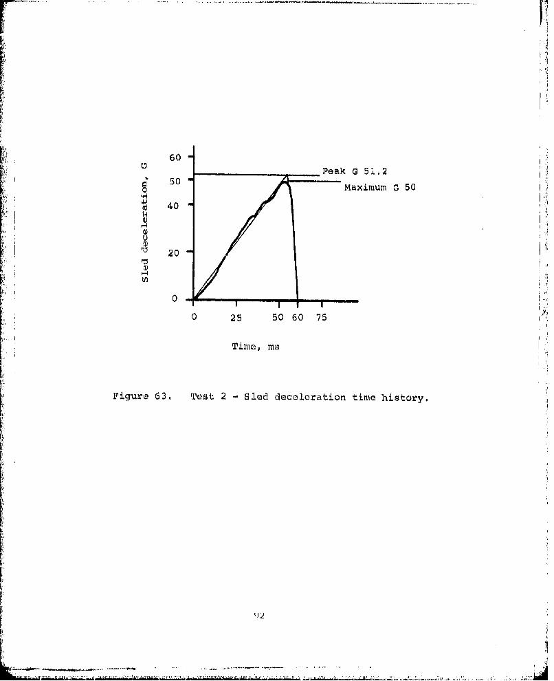
60Peak G 51.2
50 Maximum G 50
"•d 40
'-4
Ua)
•d 20
!~, I
0
0 25 50 60 75
Time, ms
Figure 63. Test 2 - Sled deceleration time history.
It 1!.
-( -
S--.--, . . . . .. .- --.- .,-

M H
0 (
II' .All

Instrumentation data showed that the maximum loads and atten-
uator strokes recorded were as follows:
Instrumented item Maximum load-lb Stroke-in.
Right lapbelt 740 (failed) -
Left lapbelt 2400 -Right shoulder strap 2000Left Shoulder strap 1100Front diagonal cable 1400 .3Rear diagonal cable 600 1,8Right diagonal strut 700 0Left diagonal strut 1300 .8Right ceiling attenuator - 8.9Left ceiling attenuator 6.7
Although the accelerations recorded on the dummy were wellwithin tolerance limits, the data is not reliable due to therotations which occurred after lapbelt separation.The conclusion reached after analysis of the test data is thatthe seat was functioning properly up to the point of lapbeltbuckle failure. The attenuators were stroking as required anddummy accelerations were within tolerance.
Test 4 - Rear-Facinc StForward Yaw Loading
A rearward-facing seat was installed on the test sled andoriented in a 30-degree yawed position. A 53th percentiledummy with combat equipment was strapped into the seat; itweighed a total of 243 lb (Figure 66). The sled was acceler-ated horizontally and impacted the barrier at 50 fps.
After impact, a sequence of failurus occurred, The dummy con-tactod the seat pan support strap attachment, shearing thesheet metal bracket. This allowed the dummy t, penetrate theseat back support and contact the tubular back frame. Afailure then occurred at the upper right corner of the seatback where the intersecting tubes are welded (Figure 67).Although the seat was extensively damaged, the dummy remainedrestrained by the seat,
Review of the acceleration data shows that in splte of thoseat daniagi, the dummy received a relatively smooth ride downand acceleratlons about all axes were within tolerance limits.However, the data was unreliable duc to dummy rotation.
Other instrumentation data showed the MXiimuM loads andiitttonuator strokes to be as follows:
94
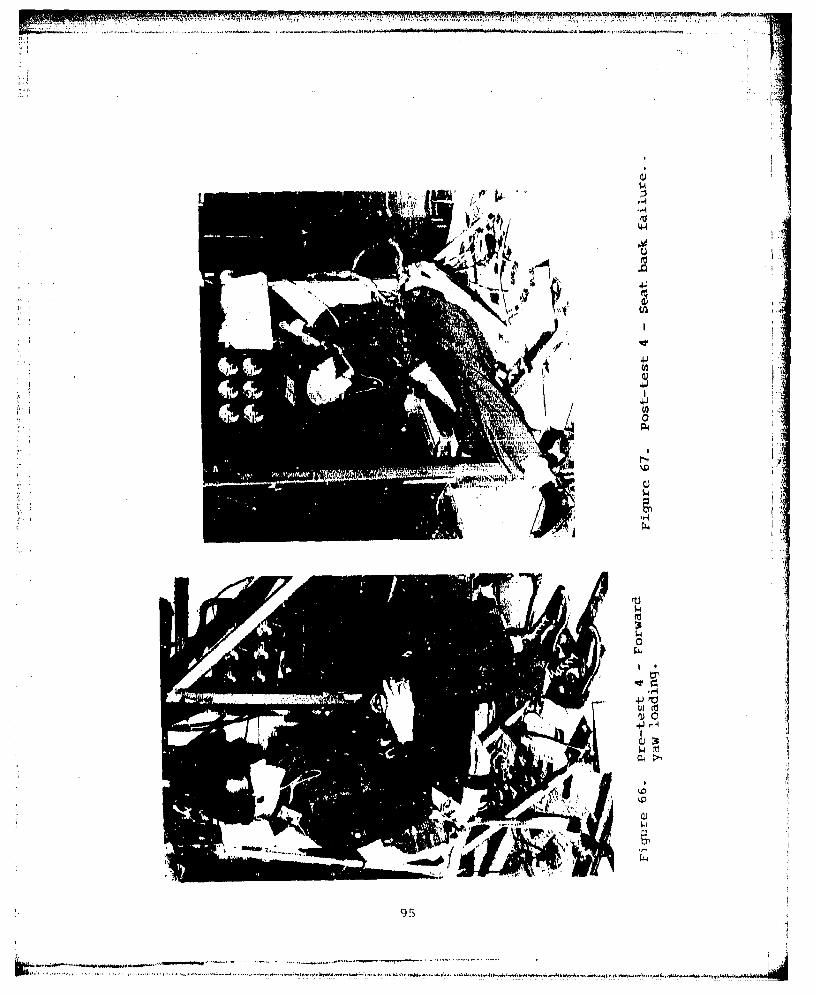
2~ 4'
'41u4Jr
9 S)
6L=A
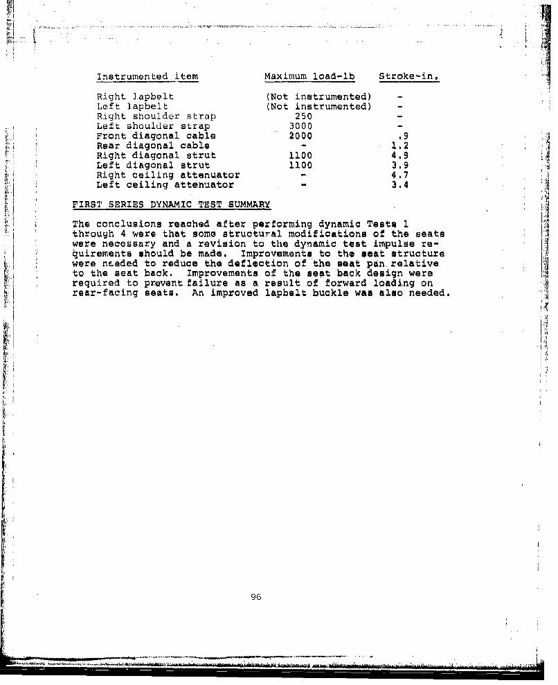
.... ....
Instrumented item Maximum load-lb Stroke-in,
Right lapbelt (Not instrumented) -Left lapbelt (Not instrumented) -Right shoulder strap 250 -Left shoulder strap 3000 -Front diagonal cable 2000 .9Rear diagonal cable 1.2 IRight diagonal strut 1100 4.9Left diagonal strut 1100 3.9Right ceiling attenuator - 4.7Left ceiling attenuator - 3.4
FIRST SERIES DYNAMIC TEST SUMMARY
The conclusions reached after performing dynamic Tests 1through 4 were that some structural modifications of the seats !Awere necessary and a revision to the dynamic test impulse re-4uirements should be m&de. improvements to the seat structurewere needed to reduce the deflection of the seat pan. relativeto the seat back. Improvements of the seat back design wererequired to prevent failure as a result of forward loading onrear-facing seats. An improved lapbelt buckle was also needed.
96
- -- i n u i I l i
-- =7 .: ;
DYNAMIC TESTING AND ANALYSIS (SECOND SERIES)-
Additional dynamic testing was required with modified seatsand revised dynamic impulse requirements. The following struc-tural modifications were made to the seats.
1. Roplace the welded tubing seat back assembly withhigher strength tubing, using mechanical joints.
2. Move the seat pan support point 1 in. further forwardon the seat to reduce the moment arm.
3. Replace the seat pan support strap with strongerwebbing.
4. Replace ti-e seat pan support attachment sheet metalbracket with a round bar loop fitting.
5. Replace the seat pan welded corner fittings with one-piece formed tubing.
6. Replace the lapbelt buckle with simulated buckle usingtwo aluminum plates bolted together to connect strapends.
Revisions to the dynamic test requirements were as follows:
1. Change the predominantly vertical three-axis impactvelocity requirement from 50 fps to 42 fps, the sameas the pure vertical impact velocity requirement.
2. Change the occupant weight requirement for predominantlyvertical impact from 95th percentile with full combatequipment to 95th percentile with no equipment, or 50thpercentile with full equipment.
3. Forward impact velocity and occupant weight shouldremain the same.
Six modified and refurbished seats were sent to the FAA (CAMI),Oklahoma City, for the second series of dynamic tests. Thefour test conditions of the first test series were repeatedwith slight variations. Velocity for the predominantly verti-cal three-axis impact condition was reduced from 50 to 42 fpsand no equipment was included with the 95th percentile dummy.No changes were made in impact acceleration, velocity, ordummy and equipment weight for the forward impact tests.
The sequence with which the second series of dynamic testswere conducted was not the same as the first series. Discus-sions on the second series of tests will be presented in the
97

order that they were performed, However, the test number willbe the same for similar tests of both series; a letter suffixdesignates the repeat of a given test.
Test 1A - Forward-Facing Seat, Three-Axis Loading
A modified forward-facing seat was installed in the dynamictest fixture in a manner similar to dynamic Test 1. A 95thpercentile clothed dummy with no equipment and weighing 212lb was restrained in the seat (Figure 68). The seat wasoriented to simulate 30-degree pitch down and 10-degree roll, jthen was rotated back 90 degree so that a vertical drop couldbe simulated on the horizontal accelerator sled. A velocityof 41.9 fps was achieved at the time of impact. .A visual inspection of the seat made after the test revealedno structural damage (Figure 69). There was no indicationthAt the seat had bottomed out, and a review of the motionpicture film verified this fact. The increased strength ofthe modified seat pan suppo:t strap reduced elongation andeliminated pitch-down of the seat pan, which contributed to! • bottoming in the previous test, Both vertical attenuators i
had stroked: the right 9.5 in. and the left 10 in. Sincethis was a predominantly vertical impact, the diagonal-strut :Vattenuators under the seat were not required to stroke. ('I
Review of the instrumentation data showed that the crash im-pulse at the floor was a maximum of 40 G and the triangularpeak G was calculated to be 44.9 G over a time base of .058second as a result of a 41.9-fps impact velocity (Figure 70).Accelerometers in the cheat and pelvis recorded accelerationsabout three axies. The more critical acceleration in thevertical axis showed a sine wave curve with an initial over-shoot peak of 24 G recorded at the dummy's chest (Figure 71).A second overshoot occurred reaching a peak of 32 G. The firstovershoot is attributed to the manner of testing which simu-lated a vertical impact by using a horizontal track. Initialimpact resulted in acceleration of the dummy against the seatpan. The characteriitics higher initial force required tostart attenuator stroking also contributed to the overshoot.The second overshoot was attributed to slippage of the hookand pile tape, fastening the seat back flap, which allowedthe dummy to contact the rear seat pan tube denting it.
Other peak forces recorded were as follows:
Lapbelt - 780 lbRight shoulder strap - 380 lbLeft shoulder strap - 400 lbRight diagonal strut - 430 lbLeft diagonal strut - 650 lb
98
•t'':• ' ';'.. • .. --- -* - - - - - I.•• '••, , '• , • , • •t

k igr 6. r-test 1A -Three-axis loading.
Figure 69. Post-test - Three-axis loading.
99
-~~~ ~ ...........4Lh . VA .. ~~

*50.0 •Peak G 44.904.)
Maximum G 40CA
25
F-4- ,
0 25 50 755S
Time, me
Figure 70. Test 1A - Sled deceleration time history.
U 'I25
0
Ti10, ms
Figure 71. Test 1A -Vertical acceleration, dummy chest.
100
: ,0(ViUJ
U!
The test conclusions are that the seat functioned as intended,but overshoot accelerations were excessive, Some refinementscould be made, however, to reduce overshout by attenuator andback flap modifications.
Test 3A - Forward-Facing Seat - Forward Yaw Loading
A modified forward-facing seat was installed on the test sledand oriented in a 30-degree yawed position. A 95th percentiledummy with combat equipment was strapped into the seati it,weighed a total of 243 lb (Figure 72). The sled w&*. 'celer,-ated horizontally and impacted the barrier at 49.5 fr....
A visual inspection of the seat was made after the test and nostructural or fabric damage was detected (Figure 73), A reviewof the motion picture film showed that the dummy was retainodin a proper position throughout the seat stroking sequence.The seat deflected 30 degrees to the left from its originalyawed position to align itself in the direction of impact.Swivel fittings at the point of attachment to the floorallowed the seat to realign itself.
All of the attenuators intended to stroke did stroke. The leftand right upper attenuators stroked 6.8 and 6,5 in,, respec-tively (Figure 74) . The left and right diagonal-strut attenu-
ators stroked 3,4 and 6,4 in., respectively (Figure 75),
A review of the instrumentation data showed that the crashimpulse measured at the floor was a maximum of 19 G with thepeak G calculated to be 23.6 G for a time base of .130 second(Figure 76), Plateau peak accelerations measured on the dummywere well within limits, The accelerations in the frontwarddirection (x axis) were 15 G on the pelvis and approximately15 G on the chest with a maximum peak of 23 G recorded (Figure77). The accelerations to the side (y axis) were 7 and 10 Gon the pelvis and chest, respectively. Vertical accelerations(z axis) were 12 and 10 G on the pelvis and chest, respectively(Figure 78),
other peak forces recorded were as follows:
Right lapbelt - 2450 lbLeft lapbelt - 1400 lbRight shoulder strap - 1300 lbLeft shoulder strap - 1320 lbRight diagonal strut - 830 lbLeft diagonal strut - 760 lbRear diagonal cable - 400 lb
101
. . •---'..................................................... T.................... .

TI'
Fiue.3 Prost-test 3A ..-..o.rwar yaw loading. -
102
...................... ...~......

9To
Figure 74. Stroked vertical attenuators.
Figure 75. Stroked diagonal-strut attenuators.
1.03
...... .....

4 0
1.9.
"L-
LI
N¢
1044
....
InJ

inn n'., j:.
.~~ ... ....
~ -ii--- 4
I',.
V) 4
:1: .d
rd,
'U 0l
'U N
105
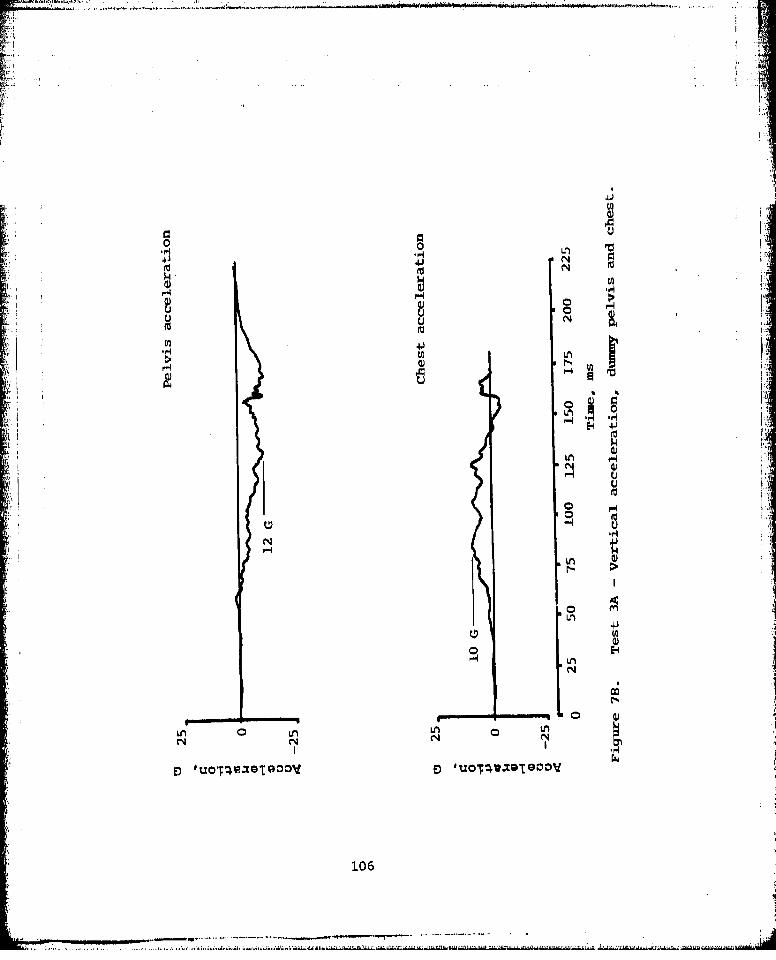
43 N
N
r44W U
p.41
N
u
.9 -4
N CN N
106

it
The test conlusions are that the seat system functioned asrequired. All attenuators required to stroke did stroke andreduced the accelerations on the 95th percentile occupant towell within the desired limits. Extrapolation of the data in-dicates that a 5th percentile occupant would not exceed thehuman tolerance limits.
Test 4A - Aft-Facing Seat, Forward Yaw Loading
A modified rearward-facing seat was installed on the yest s9edand oriented in a 30-degree yaw position. A 95th percentildummy with combat equipment was strapped into the seat; itweighed a total of 243 lb (Figure 79). The sled was accel .-
ated horizontally and impacted the barrier at 48.5 fps.
A visual inspection of the seat was made after the test and nostructural or fabric damage was detected (Figure 80). However,the front diagonal cable anchor pulled out due to the use of ashear nut rather than a tension nut. A review of the motionpicture film showed that the dummy was retained in a properposition throughout the seat stroking sequence. The onlyexception was the right arm flailing and contacting the seatback.Orientation of the seat changed during the stroke sequencefrc~m the 30-degree yawed position to approximately a 45-degreeposition. This was attributed to the center of gravity of thedummy being off center and behind the seat, which tended tocause sn~e rotation of the seat away from an alignment position.This tendency is a reversal of the forward-facing seat, whichtends to align itself. Loss of the diagonal cable also con-tributed to the additional seat rotation.
All of the attenuators intended to stroke did stroke. The leftand right upper attenuators stroked 4.3 and 5.5 in., respective-ly. The left and right diagonal-strut attenuators stroked 6in. and 8 in., respectively (Figure 81).
A review of the instrumentation data showed that the crash im-pulse measured at the floor was a maximum of 27 G. The calcu-lated triangular peak was 26.2 G for a time base of .115 second(Figure 82). Accelerations measured on the dunmy were wellwithin limits. Chest accelerations were 21, 10, and 12 G inthe x, y, and z axes, respectively (Figure 83). Similar levelswere recorded at the pelvis.
Forces recorded on the restraint system were negligible due tothe dummy being forced into the seat back. Peak forces of1000 and 1100 lb were recorded on the left and right diagonal-strut attenuators, respectively.
107

L :
108k
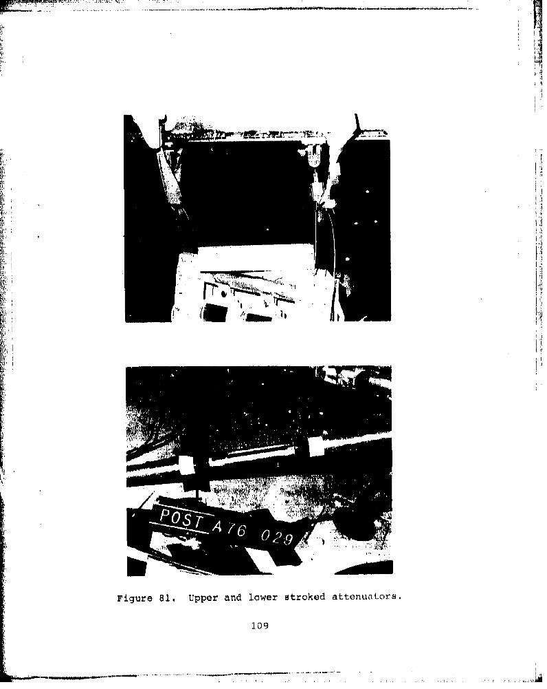
.. .:-77w-
kit'
011
Figure 81. Upper and lower stroked attonuators.
109
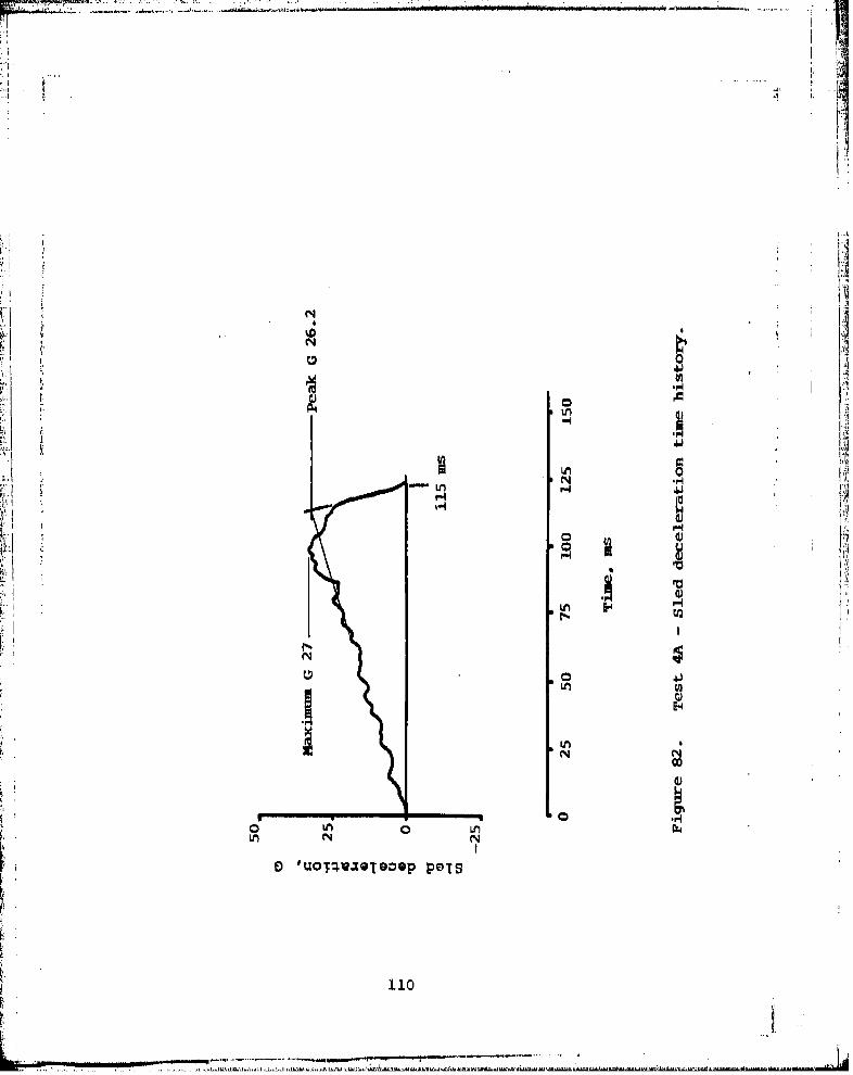
"" S.4 M
,1I
II
•)'UOT•U.ZQl•OQP POTS
1.10
- "-.. .............. ... .....................
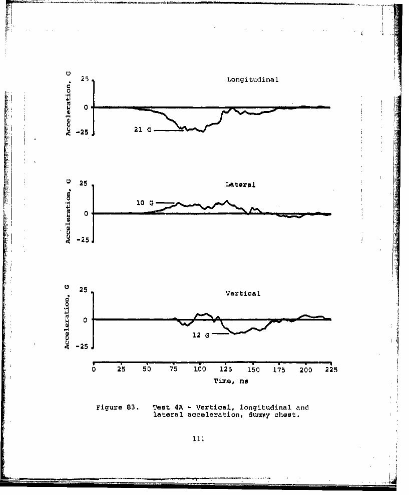
t.
25 Longitudinal
0
• -25 21 G
0 25 Lateral
10 a0
-25
S25 Vertical
f-4
- 12
, -25
i0 50 75 100 125 150 175 200 225
Time, me
Figure 83. Test 4A - Vertical, longitudinal andlateral acceleration, dummy chest.
111

The test conclusions are that the seat system functioned asrequired. All attenuators required to stroke did stroke andreduced the accelerations on the 95th percentile occupant towell within the desired limits. These acceleration levels canbe extrapolated to show that accelerations on a 5th percentileoccupant would also be within limits. Replacement of thediagonal cable anchor fitting nut will prevent pullout.
Test 2A - Aft-Facing Seat, Three-Axis Loading
A modified aft-facing seat was installed in the test fixtureand a 95th percentile dummy without combat pack, weighing 220lb, was strapped into the seat face down (F'igure 84). The seatwas pitched back 30 degrees and rolled 10 degrees. The sledwas accelerated horizontally to simulate a vertical drop andimpacted the barrier at 42.3 fps.
A visual inspection of the seat after the test revealed nostructure or fabric damage (Figure 85). Both vertical atten-uators had stroked 11 in. (Figure 86). The diagonal-strutattenuators did not strokel they are not intended to strokein predominantly vertical impacts. There was no physical Kevidence of the seat having bottomed, and review of the motionpicture film showed that the seat had approximately 2.5 in. ofadditional stroke remaining before making contact with thefloor. ,
A review of the instrumentation data showed that the crash im-pulse acceleration was higher than desired, but the time basewas shorter. A maximum of 45 G was recorded and the peak Gcalculated was 52.5 G for a time base of .050 second (Figure87). Vertical accelerations recorded on the dummy's chestshowed an initial overshoot of 25 G which was attributed tothe manner of testing and the characteristic higher initialforce required for attenuator stroking (Figure 88). The dummywas suspended from the meat face down to simulate verticalacceleration by using a horizontal test track. Looseness ofthe dummy in the seat caused higher accelerations as the dummycontacted the seat pan at impact. Vertical accelerations atthe chest dropped to a plateau of 12 G after the initial over-shoot. Longitudinal accelerations on the chest were withinlimits, with a plateau at approximately 14 G and a maximumpeak recorded of 23 G (Figure 88). Accelerations recordedon the pelvis were lower than the chest accelerations.
Forces recorded on the restraint system were negligible due tothe rear-facing orientation. Maximum peak forces recorded onthe left and right diagonal-strut attenuators were 750 and1000 lb, respectively.
1.12
.. ....
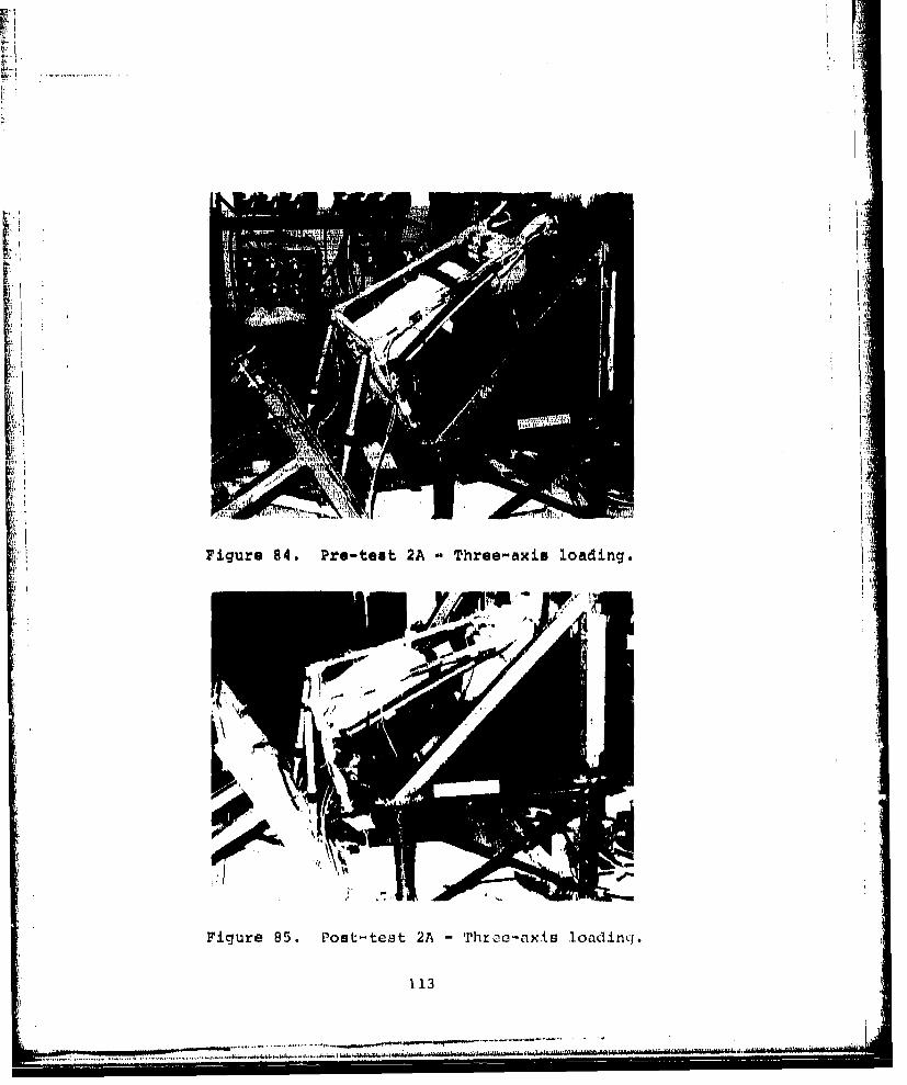
I.
Figure 84. Pre-test 2A - Three-axis loading.
Figure 85. Post-test 2A - Throa-axis loading,.
113
.M2'I&~%J&,~I.lM MMM.J4JAMlMhIMMM1J

Figure 86. Stroked vertical atteznuators.
114
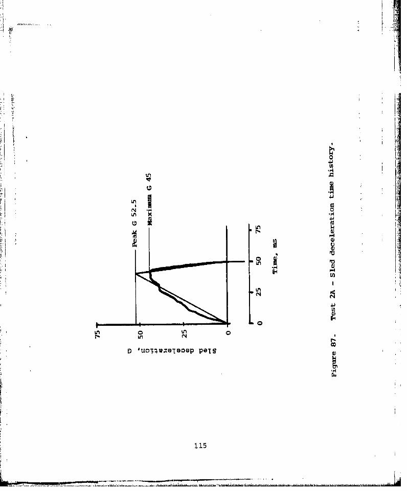
IL
to- -
LA M
LMw 0
1151
..........
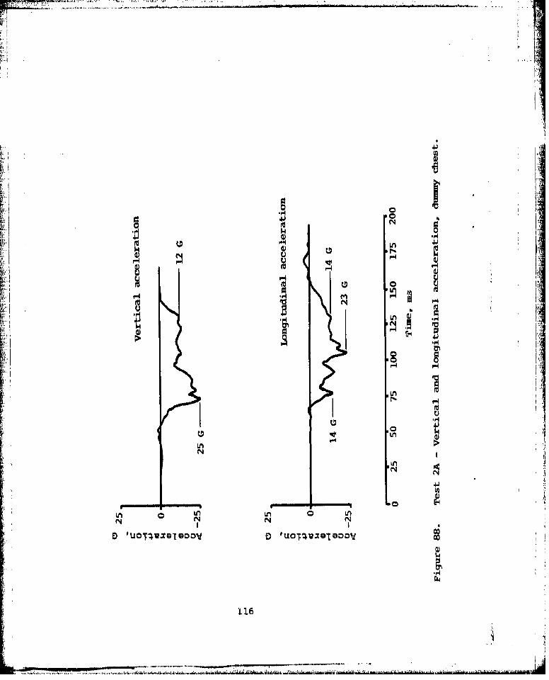
Li 0
~~IAa) 1n
Ln
HL
H 2M~jI ,' UN
Ln L
0116
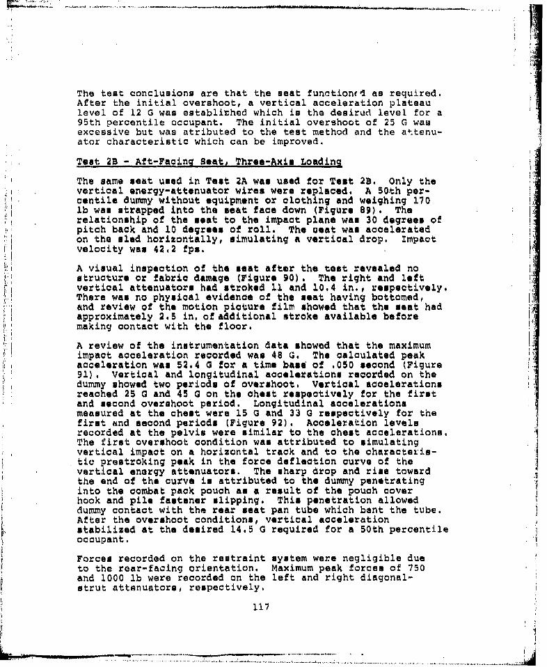
The test conclusions are that the seat functionud as required.After the initial overshoot, a vertical acceleration plateaulevel of 12 G was establithed which is the desired level for a95th percentile occupant. The initial overshoot of 25 G wasexcessive but was atributed to the test method and the attenu-ator characteristic which can be improved.
Test 2B - Aft-Facing Seat, Three-Axis Loading
The same seat used in Test 2A was used for Test 2B. Only thevertical energy-attenuator wires were replaced. A 50th per-centile dummy without equipment or clothing and weighing 170lb wan strapped into the seat face down (Figure 89). Therelationship of the seat to the impact plane was 30 degrees ofpitch back and 10 degrees of roll. The ceat was acceleratedon the sled horizontally, simulating a vertical drop. Impactvelocity was 42.2 fps.
A visual inspection of the seat after the tost revealed nostructure or fabric damage (Figure 90). The right and leftvertical attenuators had stroked 11 and 10.4 in., respectively.There was no physical evidence of the seat having bottomed,and review of the motion picture film showed that the seat hadapproximately 2.5 in. of additional stroke available beforemaking contact with the floor.
A review of the instrumentation data showed that the maximumimpact acceleration recorded was 48 G. The calculated peakacceleration was 52.4 G for a time base of .050 second (Figure91). Vertical and longitudinal accelerations recorded on thedummy showed two periods of overshoot. Vertical accelerationsreached 25 G and 45 G on the chest respectively for the firstand second overshoot period. Longitudinal accelerationsmeasured at the chest were 15 G and 33 G respectively for thefirst and second periods (Figure 92). Acceleration levelsrecorded at the pelvis were similar to the chest accelerations.The first overshoot condition was attributed to simulatingvertical impact on a horizontal track and to the characteris-tic prestroking peak in the force deflection curve of thevertical enorgy attenuators. The sharp drop and rise towardthe end of the curve is attributed to the dummy penetratinginto the combat pack pouch as a result of the pouch coverhook and pile fastener slipping. This penetration allowed Idummy contact with the rear seat pan tube which bent the tube.After the overshoot conditions, vertical accelerationstabilized at the desired 14.5 G required for a 50th percentileoccupant.
Forces recorded on the restraint system were negligible dueto the rear-facing orientation. Maximum peak force. of 750and 1000 lb were recorded on the left and right diagonal-strut attenuators, respectively.
117
MrPI

• , ............. . ... . ...... ...... ... .. . . .. . . . .. . .. . . ..,
SW..
Figure 89. Pro-tout 23B Three-axis loading.
AI
Figure go. Pout-test 2B -Threo-~axis tondinql.
A .. . U ~~ ±1
t .. ij.,.+

LMw
.9.
NK
Ln N
119.
.. ......
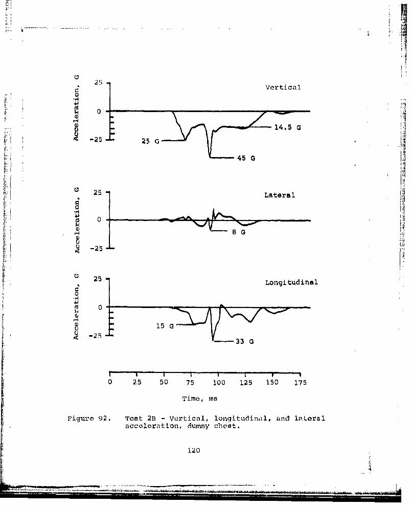
ii
251
25 Vertical
014J
S.14.5 G
S-25 - 25 ai45 A r5
25 tLateral
0A p
8 GUS-25
S25 -25Longitudinal
0
m 0
C. " 15U
S'~-----33 Q
I - i I I ' " I I . . . .I '
0 25 50 75 100 125 150 175
Time, Ins
Figure 92. Test 2B - Vertical, longitudinal, and laLeralacceleration, dumny chest.
120
""914 Ai

SECOND DYNAMIC TEST SERIES SUMMARY
Conclusions reached after completing the second series ofdynamic tests were that all seats functioned properl.y, allattenuators stroked as required, seat integrity was maintainedand the dummy was restrained in the seats in a proper attitude.Some difficulty was experienced with overshoot conditions inthe predominantly vertical impact tests. These overshoot con-ditions were attributed to three factors:
1. The method of testing simulated vertical, impact byrotating the seat 90 degrees and accelerating thetest specimens on a horizontal track. This pro-cedure vequired slinging the dummy from the seat backor laying the dummy on the seat back, creating loose-ness between the dummy and the seat pan. Impactcaused additional acceleration of the dummy into theseat pan.
2. The characteristic higher initial force required tostart attenuator stroking also attributed to theinitial overshoot condition.
3. The seat back flap, used when a combat pack was notworn, was secured with hook and pile tape whichslipped under load, allowing dummy penetration into thecombat pack pouch. Contact with the rear seat pan tuberesulted due to this condition causing a second over-shoot spike. ,
Acceleration level plateaus achieved between and after the over-shoot conditions were within thn specified levels for the 95thend 50th percentile occupants tested and can be expected to bewithin the specified tolerances for a 5th percentile occupant.Overshoot conditions can be minimized hy improved designs ofthe attenuators and seat back flap attachments. Use of avertical drop tower facil.ity would minimize the overshoot con-dition experienced as a result of simulating vertical drops ona horizontal track.The assembly drawing for the seat, as modified for these tests,
is attached at the end of the report (Page 201). The totalweight for the seat system, as modified, using quick-fix methods,wac 17.2 lb. Of this weight, tha restraint system weighed2.2 lb. Weight of the seat and restraint system can be reducedbelow 15 lb by design optimization and material selection.
121

r' DYNAMIC TESTING AND ANALYSIS (THIRD SERIES)
Recommendations were made that the two remaining seats nottested be used for a third series of dynamic tests. Theprincipal objective was to reduce the initial accelerationpeak recorded on the dummy in the vertical axis. Designmodifications were made to the vertical energy-attenuatorwire to change from the configuration which had the wiretangent to both rollers, to a configuration which has aslack loop between the first and second roller. This arrange-ment would permit the attenuator to start strokiig at a lowerload, thereby eliminating the initial starting peak,
* A new attenuator wire configuration was designed with a slackloop before the wire passes over the second roller (Figure93). Pull tests were conducted on the new configuration andcompared with similar tests on the old configuration wire.As anticipated, the initial peak in the force deflectioncurve, produced by the original wire, was eliminated (Figure94). Additional tests were run using the old wire config-uration to determine the effect of various lubricants on thewire. No change in the force levels were noted as a result ofapplying various lubricants (Figure 95).
Two seats were modified with the newly-configured upper atten-uator wire. These seats were sent to the FAA (CAMI), OklahomaCity, for the third series of dynamic tests.
The test objective was to determine the effect of the newvertical energy attenuator on reducing the initial peakvartioal acceleration on the occupant. vertical, three-axis
* impact conditions were repeated for a forward-facing and anaft-facing seat. The test impulse objective was a 42-fpsimpact velocity with an acceleration of 48 G and a time baseof .054 seconds. A 50th percentile clothed dummy with fullcombat equipment was used. The same test number used onsimilar previous tests will be used for the test discussion;
"W/ a letter suffix designates the repeats of a given test.
Test 2C - Aft-Facing Seat, Three-Axis Loading
The same seat used in Test 2A and 2B was used for Test 2C:only the vertical energy-attenuator wires were replaced. A50th percentile dummy with equipmont and clothing and weigh-ing 204 lb. was strapped into the seat face down (Figure 96).The relationship of the seat to the impact plane was 30degrees of pitch and 10 degrees of roll. The seat wasaccelerated on the sled horizontally, simulating a verticaldrop. The impact velocity was 49.04 fps, 7 fps above thedesired velocity of 42 fps.
X 22
V-
Slack area
r~o 1 ler
II
I III
Figure 93. Slack-loop energy-attenuator wire.
123

In
1400.
1200
S1000
800
Boo
Slack-loop wire force/deflection.1600
1400
21200.
1000Blooo:800
0I
Tight-loop wire force/deflection
0 1 2 3 4 5 6 7 8 9 10 11 12
Extension, in.
Figure 94. Force/deflection comparison, tight and slack loop.
124
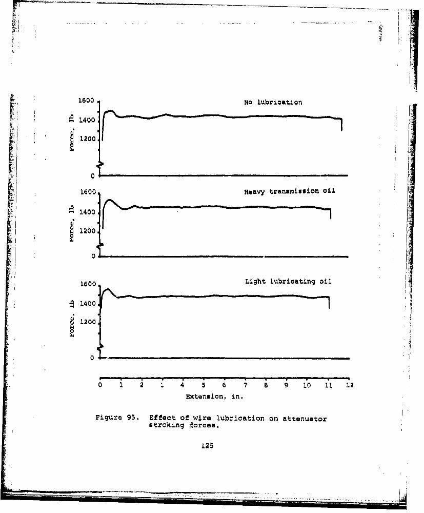
1600 NIo lubrication* ~ 21400f1200
0
1600 Heavy transmiission oil.
1400
12 l00.
1600 Light lubricating oil
S1400
1200.
0
0 1 2 . 4 5 6 7 8 10 11 1
Extension, in.
Figure 95. Effect of wire lubrication on attenuatorstroking forces.
125

F7-
Figure 96. Pro-test 2C -Three-axis l.oading.
Fiqit.irc 97. Post-tost 2C -Throe-axis loadingj.
12 (l
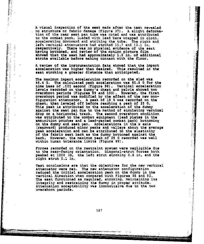
A visual inspection of the seat made after the test revealedno structure or fabric damage (Figuve )7). A slight deforma-tion of the rear seat pan tube was noted and was attributedto the combat pack, lc.~aded with lead bars wrapped in cloth,accelerating downward and striking the tube. The right andleft vertical attenuators had stroked 11.7 and 32.1 in.respectively. There was no physical evidence of rhe seathaving bottomed, and review of the motion picture filmshowed that the seat had approximately 1.5 in. of additionalstroke available before making contact with the floor.
A review of the instrumentation data showed that the impactacceleration was higher than desired. This resulted in theseat stroking a greater distance than anticipated.
The maximum impact acceleration recorded on the sled was46.4 G. The calculated peak acceleration was 60.9 0 for thetime base of .050 second (Figure 98). Vertical accelerationlevels recorded on the dummy a chest and pelvis showed twoovershoot period* (Figures 99 and 100) , However, the first
r overshoot period was modified by the effect of the new con-figuration attenuator. A peak of 19 G was recoried on the
chest, then leveled off before reaching a peak of 25 0.This peak is attributed to the acceleration of the dummyagainst the seat pan due to the method of simulating verticaldrop on a horizontal track. The second overshoot conditionwas attributed to the combat equipment (lead plates in theammunition pouches and a lead-packed combat pack) bottomingon the dummy and seat pan. Accelerations in the x axis(rearward) produced minor peaks and valleys about the averagepeak acceleration and can be attributed to the elasticityof the fabric seat back as the dummy bottomed against theback. However, the maximum peak of 25 G recorded was wellwithin human tolerance limits (Figure 99).
Forces recorded on the restraint system were negligible dueto the rear-facing orientation. Diagonal -strut forces bothpeaked at 1000 ib, the left strut stroking 0.6 in. and theright strut 0.1 in.
Test conclusions are that the objectives for the new verticalattenuator were met. The new attenuator configurationreduced the initial acceleration peak on the dummy in thevertical direction when compared with Figures 88 and 92.The seat functioned as required, stroking, maintaining itsintegrity and restraining the dummy in proper attitude.Attenuation acceptability was inconclusive due to the twoovershoot periods.
127
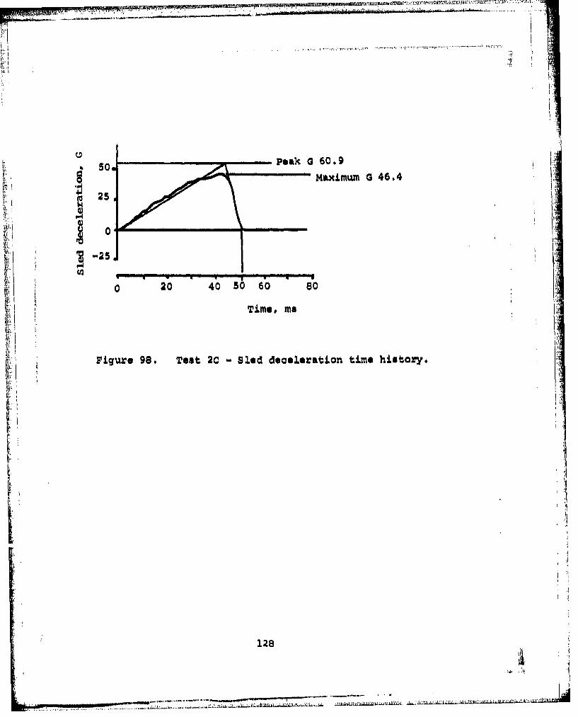
- i!
4.1l
S......peak a 60.9
50.... Maximum a 46.4
25
0
-25,
0 20 40 50 60 so
Time, ma
F'igure 98. Test 2C - Sled deoeleration time history.
128• i
I.Vertical
1.9 G----25., " m-- 2 G25 G-
tv -501
25.
lit,
S~Longitudinal
•-25, 25 G
I A4
IIII Ii I It
0 25 50 75 100 125 150 175 200
Time, mu
Figure 99. Test 2C - Vertical, longitudinal, and lateralacceleration, dummy chest.
129

25
Vertical
'-25 20 27 G
25 Lateral
0J
8-25.4
S25
5- ~Longitudinal
K0 0 .....
-25.
0 25 50 75 100 125 150 175Time, ms
Figure 100. Test 2C - Vertical, longitudinal, and lateralacceleration, dummy pelvis.
130

Teat lB - Forward-Facing Seat, Three Axis Loading
A modified forward-facing seat with new configuration verticalattenuators waw installed in the dynamic test fixture in amanner similar to Testw 1. and 1A. A 50th percentile clotheddummy with combat equipment weighing 204 lb was restrainedin the seat (Figure 101). The seat warn oriented to simulate30 degrees pitch down and 10 degrees of roll, then wasnrotated back 90 degrees so that a vertical drop could besimulated on the horiznontal accelerator sled. The sled wasnaccelerated and a velocity of 46.6 fps was achieved at thetime of impact. This warn 4.6 fpm above the desired 42 fps,
AN visual inspection of the seat after the test revealed thatthe vertical energy attenuators had stroked only 6.1 in.,a minimum stroke of 11 in. had been anticipated (Figure 102).The rear tube of the meat pan had been bowed downward 2.8in. at the center (Figure 102).* The cause of the minimumstroke Was initially attributed'to much of the energy beingabsorbed by deformatio~n of the rear tube. However, reviewof the motion picture film revealed the cause of the minimalstroke . Vertical impact was simulated using a horiznontalaccelerator by rotating the seat 90 degrees onto its back.The legs of the dummy were held up by light *tringi duringimpact the string broke, allowing the legs to fall down underJthe meat, thereby preventing the seat from fully stroking.Teimpact of the front of the seat pan on the calves of thek
damage was detected on the meat structure or fabric.
A review of the instrumentation data showed that the maximumimpact acceleration reccrded on the sled was 46 G. Thecalculated peak acceleration was 54.2 0 for the time base of.052 second (F'igure 104) . Accelerations measured on thechest and pelvis showed the ef'fectiveness of the new verticalattenuator configuration. The initial acceleration overshoots
experienced on proviovus vertical impac~t tests was reduced toa plateau which did not exceed 17 0 on both the pelvis and
pelvis and chest reaching peaks of 36 G and 29 G respectively.Theme accelerAtions were attributed to impact of the seat panwith the dummy's legs. Restraint systemn forces were minimal
due to the predominantly vertical impact# and diagonal-strut
The test conclusion reached was that the principal objective,
determining the effect of the new attenuator configuration,was accomplished. Initial peak accelerations were flattenedas required during the initial stroking period, and this datawas not affected by the subsequent seat contact with thedummy's legs.
131
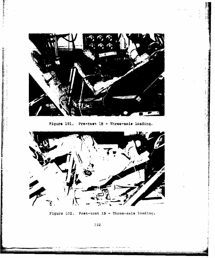
Fr
1Pigure 101. Pre-test 1B Three-axis loading.
Figure 102. Post-toBt 1B -Three-axis lcnd~incl.
1.32

I-.mpact withSdiunmiy's legs
Figure 103. Seat impact with dumomy's legs.
1 33
--1 M -

4J
Ln Lm
IFI
NN
9.4
134~
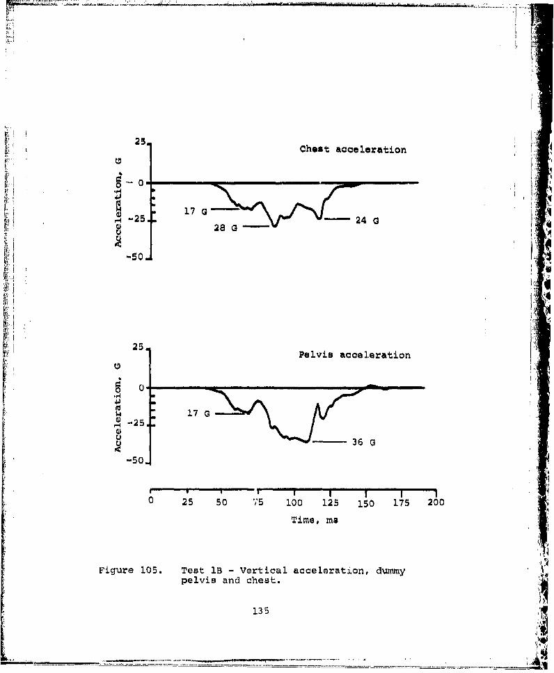
25.•
I'
25 Chest acceleration
17 G -S25. - 24 a I
28 G-
2 -5 I:
25 IPelvis acceleration
o 0w" 17 G
5 -251U 36 G
-BO
, ; . .... 5 50 V5 100 125 150 1715 2100
Time, me
Figure 105. Test 1B - Vertical acceleration, dummypelvis and chest.
"135
i i _-

Iro
_
CONeC2LUSI ONS
The crashworthy troop seat testing program demonstrated thata light weight troop seat can be designed to reduce 95th per-centile crash accelerations to within human tolerances. Theseseats and restraint systems weighed 17 lb and design opti-mization should reduce the weight to below 15 lb. The seatwithstood dynamic test loadings without failure or deformation
ik •to an extent that would jeopardize the integrity of the seat,or would preclude retention of the occupant. Table 4 showoa summary of test results.
'Uý
Overshoot excursions to 25G were recorded on predominantlyvertical impact tests 2A and 2B using 95th and 50th percentiledummies. Dynamic Response Index (DRI) was 8 for the 95th and
X :19.4 for the 50th percentile dummy, giving a spinal injuryprobability of zero and 10 percent respectively (Reference 9,Figure 1-12). A 5th percentile dummy was not tested but an18.9G plateau can be expected by extrapolating from the 12 and14.5G of tests 2A and 2B. A reasonable DRI can be expectedbecause overshoot levels were similar regardless of dummy size.Overshoot spikes can be reduced by refinement of seat designand testing procedures. In general, excursions above thespecified plateau levels, which are within the time and accel-eration limits for ejection seat design of the Eiband curvein TR71-22 (Reference 9), are acceptable.
Revisions to the testing criteria were required to permitsuccessful conclusion of the test progxam. The criteriarequire the seat to be designed for a 50th percentile occu-pant who should not exceed an acceleration of 14.5 + IG in avertical direction under a 42-fps impact, with a peak pulseof 480. The critaria also require the seat to be designedfor a predominantly vertical impact with forward and lateralcomponents and impact velocity of 50 fps with a 95th percentileoccupant. These requirements arw not compatible with a ceil-ing-suspended seat, which will align itself along the resultantpath and will stroke at the vertical impact setting. Insuf-ficient stroking distance was availablm in the 17-in.-highseat. It was necessary to change tht :edominantly verticalimpact requirements to agree with the pure vertical impactrequirements, in order to prevent seat bottoming. Similarresults can be achieved by maintaining the 50-fps impactvelocity and reducing the acceleration from 480 to 340. Thispulse is attainable in aircraft designed with crashworthylanding gear.
136
Ji

0 00- 0 a0 N.r.
0 LM o4 LM U'jU ~Ný N, 41~ s
N~ A In M -
.~ 4 .4 -4 N0 1-
cc a 0 M l
00N m 04 LM Mf in1 co.Lr. 44 NN N N N N
a 10 N *e * a N
*~. PO A I I N N C
%D NI 144 -0 Nh N. m i
qs,4n *a
1-1, m I v N I--
~~~~ w . q
(Iw N i0 w q
44 CA (U
137
The maximum loads recorded on the restraint systems, duringnormal tests were 2,450 lb on the lapbelt and 1,320 lb onthe shoulder strap (Table 4). The draft Military Specifica-tion, Seat, Helicopter, Troop, specifies a design load of4,000 lb on each strap. These loads are necessary to allowfor a margin of safety and for reduction in strength due toaging. Ultimate strengths of 6,000 lb are established inthe specification, primarily to obtain minimum elongation.
Component tests, static tests and dynamic tests were per-formed during seat development. Each was found to benecessary and cost effective in the orderly process ofseat development.
RECOMMENDATIONS
A requirement of the crashworthy troop meat testing programwas for the contractor to recommend appropriate modificationsto the proposed draft specification MIL-S-XXXX(AV), Seat,Helicopter, Troop, and USAAMRDL TR 71-22, Crash SurvivalDesign Guide. Recommended modifications to these documentsfollow.
DRAFT TROOP SEAT MILITARY SPECIFICATION CHANGE RECOMMENDATION
Changes were recommended to the draft specification titledMIL-S-XXXX(AV), Seat, Helicopter, Troop by AVSCOM, USAARL,USAAMRDL, and Boeing Vertol. Theme comments have beencompiled and the original draft specification rewrittenaccordingly. The recommended reorganization of the specif-ication and the'.numerous comments prohibited use of thenormal procedure of cross hatching deleted items and under-lining added items. The specification has been reproducedin the modified fo m.
The specification as presented, is still in a preliminarystatus and remains to be coordinated and finalized beforeit is officially released.
138

MIL-S-XXXX (AV)
MILITARY SPECIFICATION
SEATS, HELICOPTER CABIN, CRASHWORTHY
GENERAL SPECIFICATION FOR
1. SCOPE
1.1 This specification establishes the design requirementsfor lightweight folding, crashworthy seats for use by troops/passengers in helicopters.1.2 Classification. Seats, shall be of the following types,classes, and sizes as specified (see 6.5):
Type I Passenger
Type 2 Troop
Class A Forward-facingClass B Aft-facingClams C Side-facing
Size I One man seat
Size II Two man seat
Size III Three man seatSize IV Four man meat
2. APPLICABLE DOCUMENTS
2.1 The following documents of the issue in effect on thedate of the invitation for bids or request for proposal forma part of the specification to the extent specified herein.
SPECIFICATION
FederalV-T-295 Thread, NylonQQ-P-416 Plating, Cadmium (Electrodeposited)QQ-Z-235 Zinc Coating, Electrodeposited, Require-
ments for
139
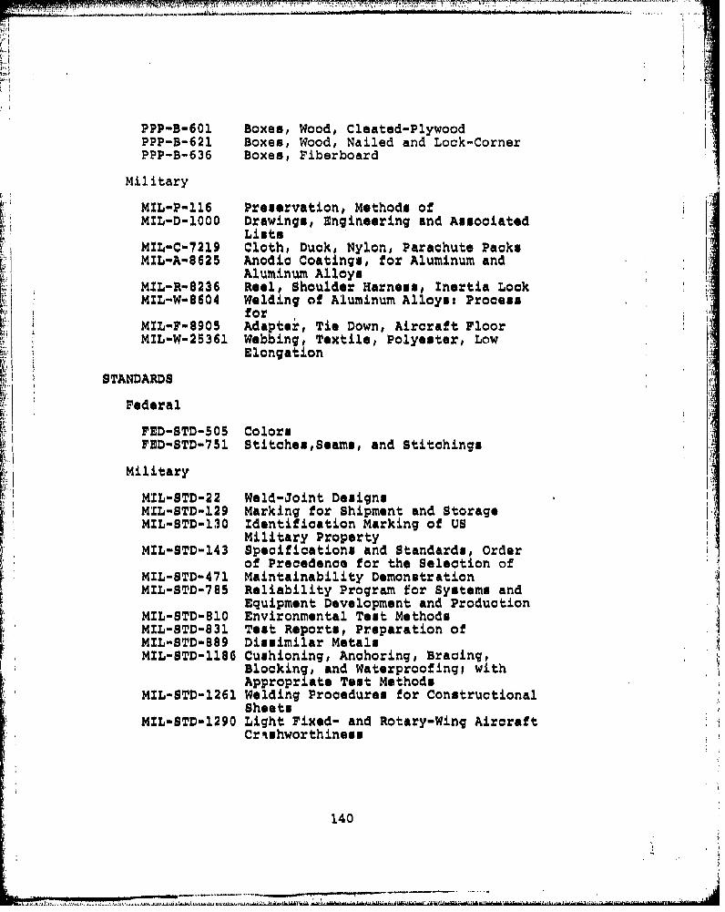
PPP-B-601 Boxes, Wood, Cleated-PlywoodPPP-B-621 Boxes, Wood, Nailed and Lock-CornerPPP-B-636 Boxes, Fiberboard
Military
MIL-P-ll6 Preservation, Methods ofMIL-D-1000 Drawings, Engineering and Associated
ListsMZL-C-7219 Cloth, Duck, Nylon, Parachute PacksMIL-A-8625 Anodic Coatings, for Aluminum and
Aluminum AlloysMIL-R-$236 Reel, Shoulder Harness, Inertia LockMIL-W-8604 Welding of Aluminum Alloys: ProcessM F9 forSMIL-F-8905 Adapter, Tie Down, Aircraft FloorMIL-W-25361 Webbing, Textile, Polyester, Low
Elongation
STANDARDS
Federal
FED-STD-505 ColorsFED-STD-751 StitchesSeams, and Stitchings
Military
MIL-STD-22 Weld-Joint DesignsMIL-STD-129 Marking for Shipment and StorageMIL-STD-130 Identification Marking of US
Military PropertyMIL-STD-143 Specifications and Standards, Order
of Precedence for the Selection ofMIL-STD-471 Maintainability DemonstrationMIL-STD-785 Reliability Program for Systems and
Equipment Development and ProductionMIL-STD-810 Environmental Test MethodsMIL-STD-831 Test Reports, Preparation ofMIL-STD-889 Dissimilar MetalsMIL-STD-1186 Cushioning, Anchoring, Bracing,
Blocking, and Waterproofingi withAppropriate Test Methods
MIL-STD-1261 Welding Procedure@ for ConstructionalShoots
MIL-STD-1290 Light Fixed- and Rotary-Wing AircraftCrishworthineus
140
- a~g.A112x,. I*..Lf .kflAA~ltki~1IUlrd~flMia~~.miI~uhi~IMM M&~M~/

PUBLICATION
MILITARY HANDBOOK
MIL-HKBK-5 Metallic Materials and Elementsfor Aerospace Vehicle Structures
REPORTSUSAAMRDL Crash Survival Design GuideTR 71-22
U.S. ARMYNatick LabsTR 72-51-CE The Body Size of Soldiers
(Copies of specifications, standards, publications, andreports required by suppliers in connection with specificprocurement functions should be obtained from the procuringactivity or as directed by the contracting officer.)
3. REQUIREMENTS
3.1 Specification sheets. The individual item requirementsshall be as specifled herein and in accordanco with theapplicable specification sheets. In the event of any conflictbetween requirements of this specification and the specif-ication sheet, the latter shall govern.
3.2 First article. Unless otherwise specified, the seatfurnished under this specification shall be a product whichhas been inspected and has paused the first article inspectionof 4.4.
3.3 Design chracteristics. The seat shall accommodate thespecified type of occupant in the quantities identified foreach respective size and orientation (see 1.2). The size 1seat is the preferred configuration in order to avoidsituations where the energy absorbers of a multi-unit seatare rendered ineffective due to less than full occupancy. Tothe maximum extent practical, seat classes (see .1.2) shallbe interchangeable to enhance standardization. Seatingshould be aft-facing whenever operational requirements permit.Forward-facing is the next preference. Seating shall notbe side-facing unless absolutely necessary for operationalconsiderations. It is desirable that all seats face in thesame direction so that the seat backs protect occupants fromloose equipment which can become flying projectiles duringcrash impact.
141
_ _ _ _... .......... ...-.

- If
3.3.1 Seating surface. The seat bottom and back shall bedesigned for comfort and durability. Seat bottoms made offabric shall be provided with means of tightening tocompensate for sagging in use. Sufficient clearance betweenfabric backs and bottoms shall be provided to preclude bodycontact with seat structure when subjected to the specifiedloads (see 3.6). Headrests may be provided to preventcontact between occupant's head and seat structure. Toaccommodate back and butt packs, that troops may be wearing,the backs of Type 2 seats shall be convertible without tools,to provide the recess shown in Figure 1. Maximum time toconvert either way shall not exceed 10 seconds, and bothback supports shall meet the strength requirements.3.3.2 Crash resistance. The aeat shall prevent the 5ththrough 95th percentile occupants (see 6.3.1) from exper-iencing vertical decelerations in excess of human tolerance(see Figure 2) during crash rulses of the severity shown inFigure 3 and not experience Ltructural failure. Energy shallbe absorbed in the vertical axis by load-limiting devices.The energy-absorption stroke shall be the maximum attainablein the space between the seat bottom and the aircraft floor.In any case, not less than 14 inches of vertical strokingdistance shall be provided when measured at the occupant'scenter of gravity. The seat and restraint shall minimizeoccupant submarining (see 6.3.5) and dynamic overshoot (see6,3,6).
3.3.3 Seat attachment. Acceptable means of attaching seatsto the cabin in'r-=or are ranked below in order of desir-abilityi
1. Suspended from the ceiling with attenuators, andwall stabilized.
2. Suspended from the ceiling with attenuators, andfloor stabilized,
3. Wall mounted with attenuators.
4. Floor, mounted with attenuators.
5. Ceiling and floor mounted (vertical energy attenu-ator. above and below seat).
3.3.3.1 Attachment distortion. Seat attachments shall becapable of accommodating crash induced cabin distortionconsisting of four inch vertical displacement and a 100 mis-alignment of any attachment.
142
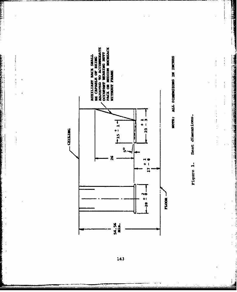
+I ~IA
1'7
143
L' miw owwAm
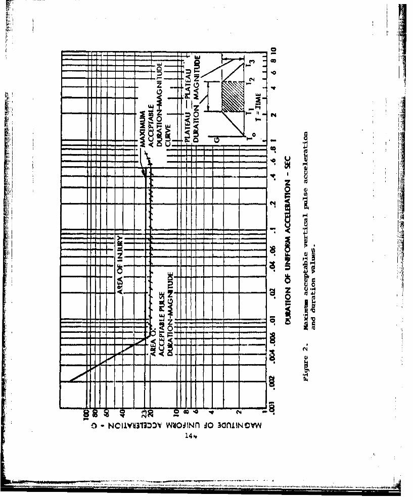
U1.-
00
-0 z
'.4)
0.0 - - *
zz
it.H
_____0 %G

TEST CONDITIONS AND SEAT ORIENTATION
TE~ST 1 TEST 2
DOWNWARD, FORWARD, AND FORWARb AND LATERAL LOADSLATERAL W•AD
4 LOAD
1 " INERTIA
"'0 tLOAD
TEST PULSE RAQUIRED *
-340G -24
&V.5 soFP AVm 50 F'PS
0.091 SEC 0,130 SEC
*The rive tio forPA PA~0the triangularpulses may vary T I MT TIMEbetween the two 04 4values illustrated. .,-
Ftgure 3. Dynamic, toot requiromentr .
145
T T
3.3.4 Seat folding stowing. Seats shall be so designedthat they may a quickly removed or folded and secured. Toolsshall not be required.
3.3.4.1 Seat disconnect time, The time for disconnectingeach Sme-i1 sea (oTne-man seat) by one man shall not exceed20 seconds. The time for disconnecting multi-unit seats byone man shall not exceed 20 seconds multiplied by the sizenumber.
3.3.4.2 Foldins and stowage. Zach seat shall be capable ofbeing folded, stowed, and secured or unstowed quickly andeasily by one man in a period not to exceed 20 secondsmultiplied by the seat size number.
3.3.5 Obstruotions. Seat suspension or mounting shall notinterfee with rapid ingress or egrese, Braces, legs, cables,straps, and other structures shall be designed to prevents snagging or tripping. Loops shall not be formed when therestraint system is in the unbuckled position.
3.3,6 Occupant restraint, The seats shall have an integralrestraint system with lap belt and self-retractinq and self-locking shoulder harness for each seating position. Therestraint shall be comfortable, light in weight, and easyfor the occupant to pgt on and remove. Reduction in supportof the occupant shall not occur due to stroking of the energyabsorbers or deformation of the seat. Strap slippage shallbe prevmnted by proper design of adjusters and webbingmaterial selection,
3.3.6.1 Lan belt. The lap belt anchorage geometry shall beas shown on Figur 4. The lap belt anchor fittings shall beattached to the stroking portion of the seat and shall becapable of displacing plus or minus 30 degrees vertically.Those fittings shall also be capable of withstanding lateralloads when the webbing is pulling at an angle of plus orminus 60 degrees to the normal plane of the fitting. Lapbelt retractors may be used in lieu of adjustors. In anyevent, lap belts shall be prevented from falling behind orbelow the seat. Flexible standups shall be provided at thelap belt anchor points to project the lap belt upward andforward 5 inches for easy reach. Retractors or adjustorsshall not be located over hard points of the occupant'sskeletal structure. The force required to adjust the webbinglength shall not exceed 3 lbs and it shall be possible forthe seated occupant to easily adjust with wither hand. Ifretractors are used, they shall not pull with more than 3 lbsforce, and shall ratchet in increments not to exceed 0.5 in.
146
i . -*

FREFERNC THIGH TANGENT- *•
2.5 0.5 IN.- .L1NE PARALLEL TO THE5.75 HORIZONTAL VISION LINE
BUTTOC LAPBELT STAID-UPRE FERPENCE.POINT
Figure 4. Lapbelt anchorage geometry.
147
.. ....... - I n.... .. k J iL js3 i4 1
3.3.6.2 Shoulder stru. Forward facing seats shall beprovided with the double-shoulder strap configuration shownin Figure 5. For aft and side facing seats, the diagonalshoulder strap configurition shown in Figure 6 shall beused. Shoulder harness anchorage geometry shall conform toFigure 7. The anchorage or guide at the top of tho seatshall not permit more than 0,5 inch lateral movement of thestrap at this point. Distance between the inner edges ofthe shoulder straps at the seat baok shall be within 3 to 5inches. Flexible guides shall be p nvided on the seat backas shown on Figure 7 to project the shou.der strap fittingsup and' ftirward o, the seat back for easy reach.
3.3.6.3 inertia reel. Shoulder strap inertia reel or reelsshall be provi-ed which pull with not more than 3 lbs forceand will fully retract the shoulder strap or straps toshoulder height in the guides described above. The reelshall be of a type which remains locked after it looks upinitially, as per the looking requirements stated in
'II MIL-R-8236 and must bu manually reset by a device on thereel. The reel shall be lobated on the seat close to theshoulder strap guide point at the back of the seat tominimize strap elongation.
3.3.6.4 Restraint buckle. The restraint harness buckleshall be a? the jquiMkretease type and require intentionalmotion by the occupant to activate it. The buckle shall beS capable of being operated with a gloved hand as well as withone finger of either hand while tension equal to the occu-pant's weight is supported by the harness. The force requiredto release it normally, as well as post crash and under theprevious condition, shall not be loss than 15 pounds nor morethan 25 pounds. The buckle shall be of a lift lever releaseconfiguration, Lap belt and shoulder strap fittings shallbe ejected simultaneously when the lever is lifted, evenwhen there is no load on the restraint straps., The lap beltshall be capable of connection without connecting the shoulderstraps, The release buckle shall be guarded tQ preventjamming of the mechanism by clothing or equipmont worn by theseat occupant causing inadvertent release.
3.4 Construction.
3.4.1 Critical members. All critical compressive structuralmembers shall be fabriTated from ductile materials having acharacteristic value of not less than 5 percent ilongation.All critical tensile and bending members shall be capable ofelongating a minimum of 10 percent prior to failure.
148
a {A~,t
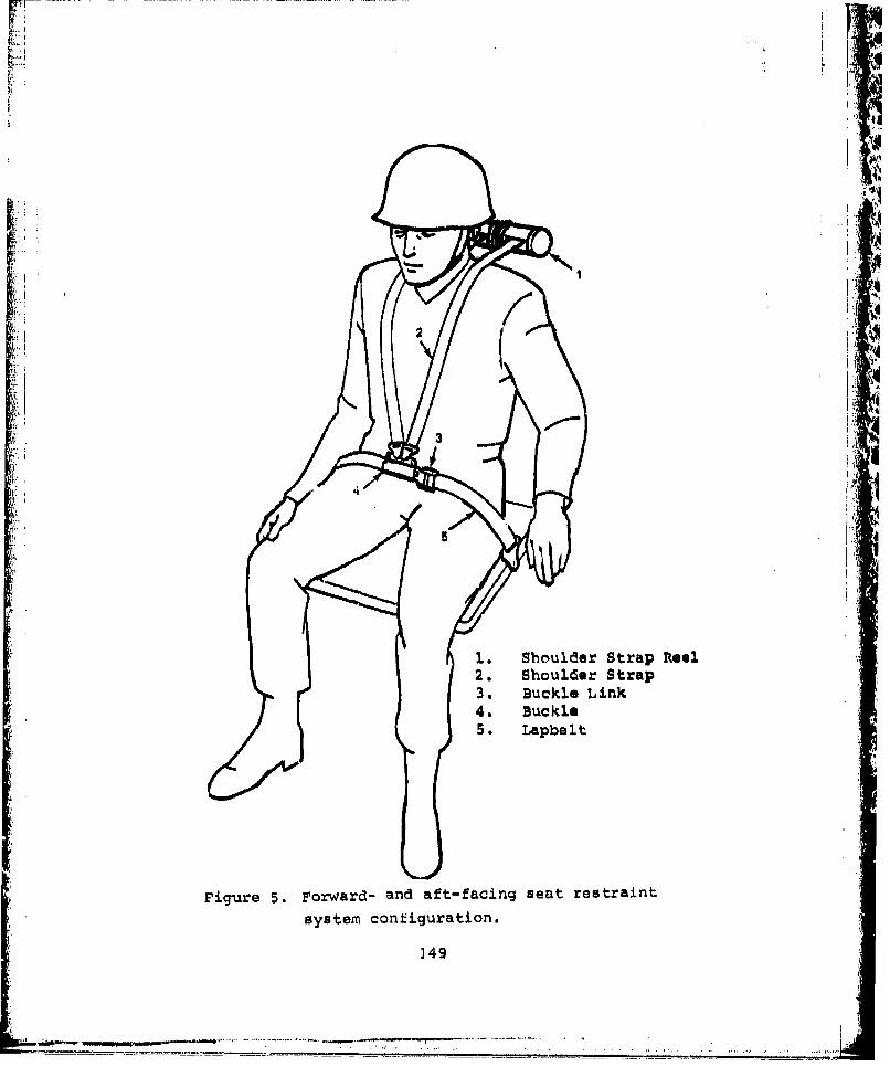
¢..,iI2
1 Shoulder Strap Ra
2. Shoulder Strap3. Buckle Link
4. Buckle •-5.• Lapbelit •
S,
Figure 5. Forward- and aft-facing seat restraint
system configuration.
3.49
"i "•:•--4a • -- • • -, " '• " " .~~~~~~~~~......... ... ........ .. .. . - ' "- T T - ' ' - -........ ....

FWD
~JI
1. Shoulder Strap Reel2. Shouldor Strap3. Buckle Link4. Buckle
5. Lapbelt
Figure 6. Side-facing seat restraint system configuration.
150

SIDE MiEW FORCE DIAGRAMRIGHNT
(TORSO CARRIES ONLY A PORTION OF SHOULDER STRAP LOAD)
J SHIOULDER STRAP GUIZDESON. 45
it RAP LOAD
... ..F-r
SHOUL.0
t4~.
Figure 7. shoulder harness anchorage geometry.
151
3.4.2 Dissimilar metals. Unless components are suitablyprotected against electrolytic corrosion, contact betweendissimilar metals shall not be used where it is feasible toavoid it. Dissimilar metals are defined in MIL-STD-889.
3.4.3 Castings, Castings used in the seat shall conform to
3.4.4 Heat treatment. Heat treatment of aluminum and steelparts shall conform to MIL-H-6088 and MIL-H-6875, respectively.
3.4.5 Structural connections. Safety factors shall be 5percent and 10 percent for shear and tensile bolts, respect-ively. Bolts less than 0.25 inch in diameter shall not beused in tensile applications. Riveted joints shall bedesigned in acoordance with MIL-HKBK-5. Welding shall be inaccordance with MIL-W-6873, MIL-W-8604, MIL-W-45204, MIL-STD-22,and MIL-STD-1261.3.4.6 Joining and Fastening, Fittings and joints requiringdisassemly for maintenance shall be bolted. All thread andstitches used for sewing seat back and seat bottom shall bein accordance with V-T-295 and FED-STD-751, Type 301,respectively.3.4.7 Standard parts. MS or AN standard parts shall beused wherever they are suitable for the purpose.
3.4.8 Resti-int construction.
3.4.8.1 Stitch pattern and cord size. Stitch pattern andcord size shall sustain a minimum of 100 pounds per inch ofstitch length, and shall comply with Figure 8.
3.4.8.2 Wrap radius. The wrap radius shall be the radiusof the fi~ttng over which the strap is wrapped at bucklesand anchorages, as shown on Figure 9. The strap wrap radiusshall be not less than 0.062 inch.
3.4.8.3 Hardware-i-o-strap folds. Figure 10illustrates arecommended method o reduce the weight and size of attach-ment fittings by folding the strap at anchorage bucklefittings.
3.4.8.4 Surface roughness of fittings. Fittings in contactwith the straps shall have a maxlmum surface roughness ofRMS-32.
152
Lb
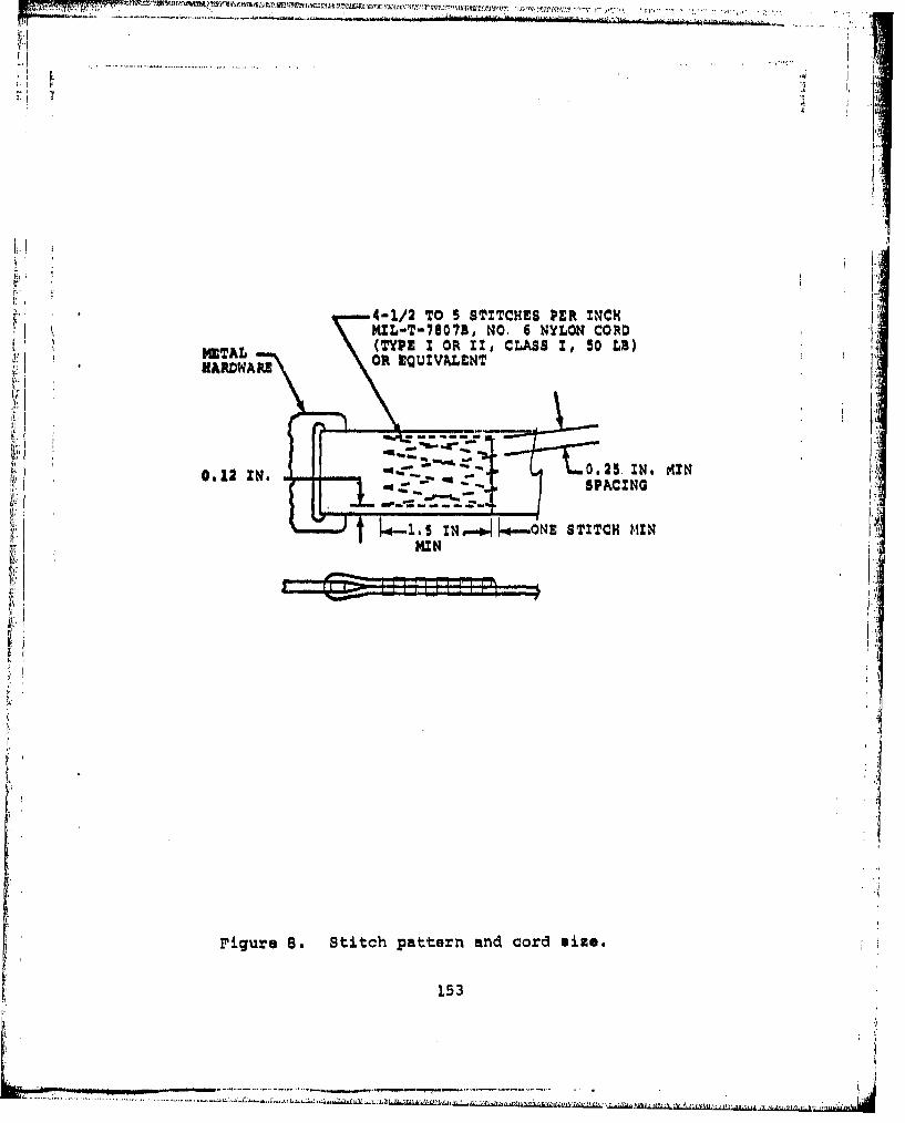
U13, 's I m: I I,,v
ii .....
K4-1/2 TO 5 SITCESER N CHRL-T-7807B, 6
IGTAL, (TYPE I OR 1I, CLASS I, 50 LB)•' • ~METAL--
Z" ,ARDWARS Olt EQUIVALENT
0.2 N 0.25.1N. AINt
1, 54. ZNp...ý4 ...mNE STITCH MIN
WIII
Figure 6. Stitch pattern and cord size.
153
,....................,..,..,..--•-

WRP RADIUS (0,062 IN. MIN)
DETAIL A
Figure 9. Wrap radium for webbing joints.
Figure 10. Webbing fold at metal hardware attachment.
154
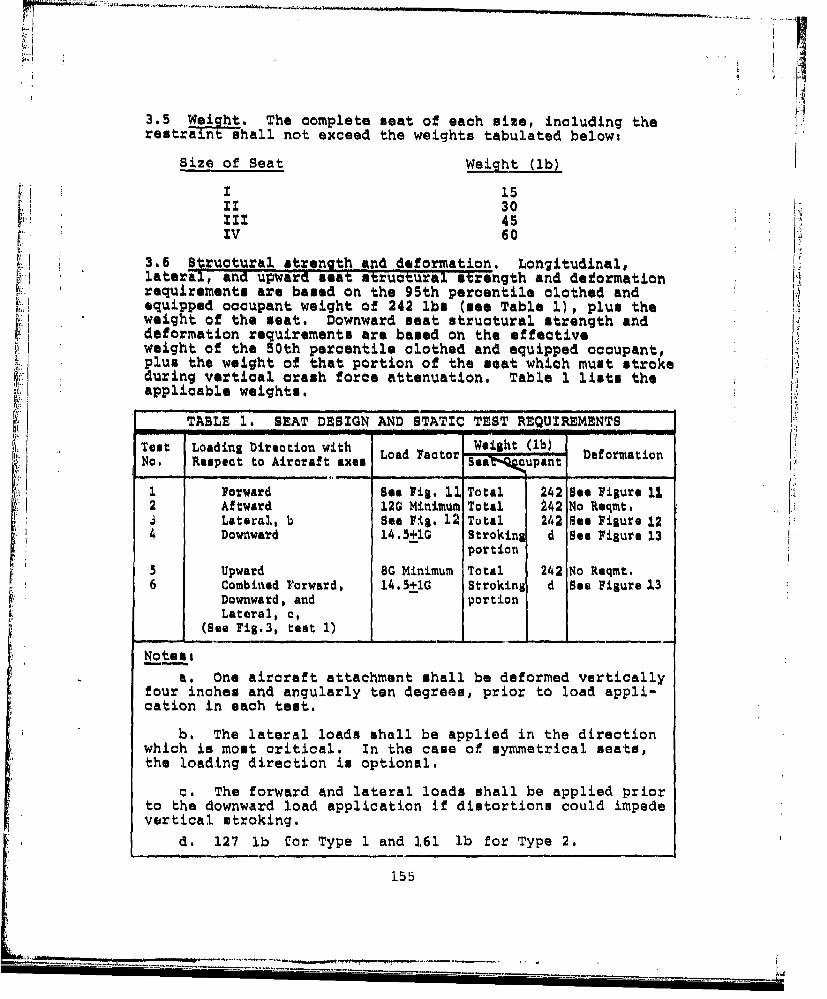
3.5 Weight. The complete seat of each size, including the
restraintishall not exceed the weights tabulated below:
Size of Seat Weight (ib)
F_. i 15II 30
III 45IV 60
3.6 Structural strength and deformation. Longitudinal,lateral, and upward seat structural strength and deformationrequirements are based on the 95th percentile clothed andequipped occupant weight of 242 lbs (see Table i), plus theweight of the meat. Downward seat structural strength and Jdeformation requirements are based on the effectiveweight of the 50th percentile clothed and equipped occupant,plus the weight of that portion of the seat which must strokeduring vertical crash force attenuation. Table 1 lists theapplicable weights.
___TABLE 1. SEAT DESIGN AND STATIC TEST REQUIREMENTS I
Test Loading Direction with Weight (lb) naxe$ ~ LodFco IDfomtoNo. Respect to Aircraft axsLa atrSea aupant omio
I Forward See Fig. 12. Total 242 Sao Figure 11.2 Aftward 12G Minimum Total 242 No Reqmt.SLateral, b see Fig. 12 Total 242 See Figure 12 F4 Downward 14.5±IG Stroking d See Figure 13 F
portion5 Upward 8G Minimum Total 242 No Reqmt.6 Combined Forward, 14.5+10 Stroking d Sea Figure 13
Downward, and portionLateral, c,
(See Fig.3, test 1)
Note__ I
a. One aircraft attachment shall be deformed verticallyfour inches and angularly ten degrees, prior to load appli-cation in each test.
b. The lateral loads shall be applied in the directionwhich is most critical. In the case of symmetrical seats,the loading direction is optional.
c. The forward and lateral loads shall be applied priorto the downward load application if distortions could impedevertical stroking.
d. 127 lb for Type I and 161 lb for Type 2.
155
• -_. . .. ' ' : . ....... ... _ _''-: .. .i•..... . .. .

I-.
3.6.1 Forward load. The meat shall have a static forwardload deflection curve measured along the longitudinal (roll)axis of the aircraft which rises to the left and above thebase area and extends into the acceptable seat failure areashown on Figure 11.
3.6.2 Aftward load. The seat strength shall be not lessthan 120 (see 5.5.,4) for aftward loads measured along the
longitudinal (roll) axis of the aircraft.
3.6.3 Lateral load. The seat shall have a static lateralload deflctilon curve measured along the lateral (pitch)axis of the aircraft which rises to the left and above thebase curve and extends into the acceptable seat failurearea shown on Figure 12.
3.6.4 Downward load. Human tolerance to vertical impactlimits the allowable forces along the vertical axis of theaircraft and necessitates energy attenuation. The seat shallhave a downward load-deflection curve measured along thevertical (yaw) axis which falls within the acceptable areaon Figure 13.
After the seat has stroked through the available strokingdistance, the seat bottom shall be supported on the floor.
3.6.5 Upward load. The seat strength upwards shall not beless than SO pare lel to the vertical axis.
3.6.6 Restraint design loads. Strength and elongationproperties of the restraints'hall conform to Table 2,
TABLE 2. RESTRAINT LOAD - ELONGATION REQUIREMENTS
Minimum Maximum MinimumStrap Elongation at Design BreakingWidth Minimum Design Load Load Strength
Use (in±0.10) Thickness (percent) (lb) (ib)
Lapbelt 2.25 .045 7.5 4,000 6,000
Double orSingle
ShoulderStraps- 2.00 .045 7.5 4,000 6,000Each
NOTE: All loads are applie in straight tension
156
MIN

__. -I_ _ __ _ __t
*I'd
bb-~
156nlon tdbt K0W i
S. ovl ovmvoi 11VI
157I
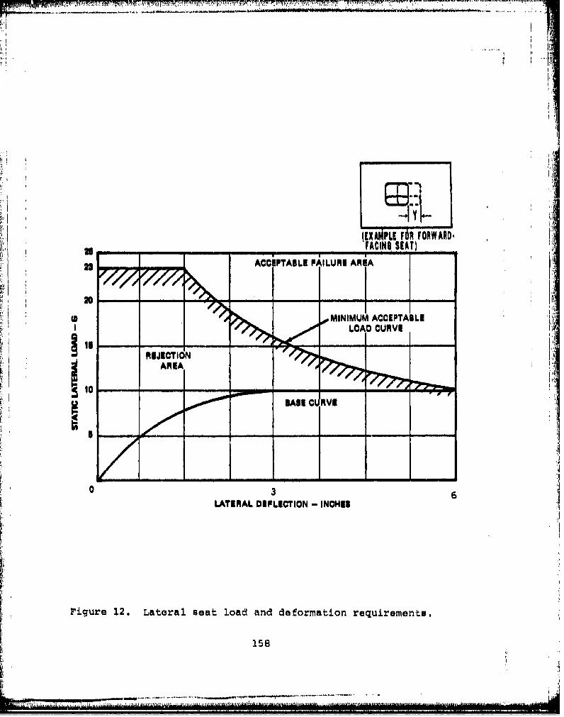
~. . . ... ...... -
Li- , . i
(EXAMPLE FOR FORWARD-
ACCEP1'ABLE FAILURE AREAPAIGSAJ
20 - ---
0 0 MINIMUM ACCEPTABLE
REJECTION4ARIA
10-
II
Bi
0 36LATERAL 0EFLICTION - INCH[$
Ise
......... .......

4.4)
[IIlk
* **s*s~s9* low
_ r4
In 1I3AO01QVNI152
......... .. ..., ..*~ * * . i... ..

ME
3.7 Materials, When specifications and standards are notspecifically desiqnated, selection of materials and processesshall be in accordance with MIL-STD-143. Materials that arenutrients for fungi shall not be used when it is feasible toavoid theml where used and not hermetically sealed, theyshall be treated with a fungicidal agent.
307.1 Flammability and Toxicity. Materials which support aself-sustained combustion and materials which, when burnedor exposed to high temperaturet give off toxic fumes, shallnot bh used,
3 8 Roliabilit-.. Except for fabric parts, the minimum life 1of all seat components subjected to normal wear and tearshall be 5,000 hours of aircraft operation and 5,000 adjust-ments, Deterioration and wear of fabric parts shall belimited so as to meeot minimum strength requirements afterfive years of use, and possess unlimited shelf life.
3.9 Maintainability, The seat uhall require no scheduledmaintenance other than the replacement of fabric cotwpo••nts.The mean time to repair for both scheduled and unscheduledmaintenance shall be less than .2 manhours.
3.9.1 interchangeability and spalaceability. Parts andassemblies of the seat shall be interchangeable or replaus.able in accordance with MIL-1-8500.
3.9.2 Tools. Maintenance operations shall not requireuncommon-tols or special equipment.
3.10 Environmental Resistance. The seaot with restraintsystem shall be capable of operating and of meeting thestructural requirements of 4.6.2 after exposure to thefollowing conditions.
3.10.1 Temnerature. The seat shall deliver the specifiedoperational and crachworthiness performanca when subjectedto the 4.6.4.1 and 4.6.4.2 temperature tests,
3,10.2 Sunshine. All nonfabric materials shall show noevidence of any degrading effect when subjected to the4.6.4.3 sunshine test.
3.10.3 Humidity. The seat shall withstand the humiditytest mpecified n 4.6.4.4.
3,10.4 F . if any material utilized in the construcLionof the seat in suspected to be a nutrient to fungi, thematerial shall show no deterioration when subjected to fungustests in accordance with 4.6.4.5.
160

3.10.5 Salt fo All materials used in the construction ofthe seat1-a--'i-&Withstand the malt fog test of 4.6.4.6.
3.10.6 Dust. The seat shall be capable of satisfactoryoperation --aftex exposure to the dust test specified in 4.6.4,7.
3.10,7 Vibration. The seat shall be ca able of satisfactoryoperation ater being subjected to the vibration tests of4.6.4.8. The oanupied and unoccupied seat shall be free ofreoonanoe within the frequenc range of the aircraft in which•it will be used and no amplification shall occur. !I
3.11 System Safty. Maximum effectiveness and conservationof Army resources dictate a need for early identification,evaluation, and correction of system hazards. A systemsafety program shall be established by the contractor inaccordance with MZL-STI'D-S82 and implemented at directed byStho procuring activity, Zia goal of the program shall be to "
insure that the optimum degree of freedom from hazard iseffectively designed into the seat system.
3.12 Dimensions. Seats shall oouilly with the dimensionsshown in Figure 1. Unless otherw se specified, a toleranceof +1/16 inch will be allowed for seat overall dimensions.Restraint system webbing dimensions shall comply with Table2 and Figures 5 and 6. The seat package, when it is in thestowed position, shall be held to a minimum size, not toexceed a thickness of six inches.
3.13 Finish.
3.13.1 Surface roughness, All exterior surfaces of theseat and rem raint shall be free from both charr' edged andcorners, or any other projections that could scratch thehands or clothing of the occupant.
3.13.2 rinishwo. Aluminum alloy parts shall be anodizedwith MIL-XT8 ,! Type I. Magnesium alloy parts shall betreated in avoordance with MIL-M-3171, Corrosive mteel part&
shall be either cadmium-plated in accordance with 0Q-P-416,zinc-plated in accordance with OO-Z-325, or chrome-plated inaccordance with QQ-C-320.3.13.3 Paint. The paint finish shall consist of one coat ofzinc-chromate primer conforming to MIL-P-8585, followed bytwo coats of enamel conforming to TT-E-489.
3.13.4 Color. The seat and restraint color shall be inaccordance with the cabin color scheme specified for theaircraft in which the meat will be used.
161
!:I
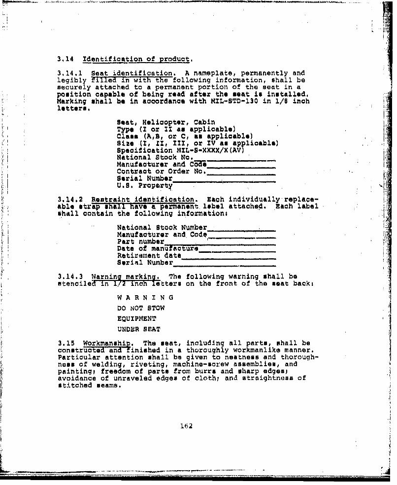
.......... .
3.14 Identification of product.
3.14.1 Seat identification. A nameplate, permanently andlegibly filled in with the following information, shall besecurely attached to a permanent portion of the seat in aposition capable of being read after the seat is installed.Marking shall be in accordance with MIL-STD-130 in 1/8 inchletters.
Seat, Helicopter, CabinType (I or It as applicable)Class (A,B, or C, as applicable)Size (I, XI, III, or IV as applicable)Specification MIL-S-XXXX/X (AV)National Stock No. _ _
Manufacturer and Ci WeContract or Order No. ___
Serial Number_ __ _U.S. Property
3.14.2 Restraint identification. Each individually'replace-able strap shall have a permanent label attached. Each labelnhall contain the following information,
National Stock Number -Manufacturer and. Codeo_._-__"____Part number -
Date of manufacture___Retirement date________________________Serial Number_ _ _ __ _
3.14.3 Warning marking. The following warning shall bestenciled in 1/2 inch letters on the front of the seat back,
WA RN I N GDO NOT STOW -,EQUIPMENT
UNDER SEAT
3.15 Workmanship. The seat, including all parts, shall beconstructed and finished in a thoroughly workmanlike manner.Particular attention shall be given to neatness and thorough-ness of welding, riveting, machine-screw assemblies, andpaintingi freedom of parts from burrs and sharp edges,avoidance of unraveled edges of clothl and straightness ofstitched seams.
162
162 :
S..~. .i
4. QUAL•TY ASSURANCE PROVISIONS
4.1 Responsibility for ins ection. Unless otherwise speci-fied in the contract or purchase order, the supplier isresponsible for the performance of all inspection require-ments as specifiea herein. Except as otherwise specifiedin th" contract or order, the supplier may use his own orany other facilities suitable for the performance of theinspection requirements specified herein, unless disapprovedby the Govwrnment. The Government reserves the right toperform Pny of the inspections set forth in the specificationwhere such irL!ections ar6 deemed necessary to assure thatsupplies and Aervices conform to prescribed requirements.
4.2 Classification of inspections. The inspection require-ments specified herein are classified as follows:
1. First article inspection (see 4.4)2. Quality conformance inspection (see 4.5)
4.3 Inspection conditions. Unless otherwise specified, allinspections shall be performed under ambient environmentalonoditions.
4.4 First Article Inspection. The first article inspectiontests shall consist of all the tests specified under 4.6.Four seats of each type, class, and size are required forthese tests, as a minimum.
4.5 Quality conformance inspections. Quality conformancetests shall consist of the following:
1. Visual examination2. Functional test
4.5.1 Visual examination. Sampling shall be in accordancewith MlL-STD-105, Inspection Level II, for the criticaldefects listed in Table 3, and Inspection Level I, for theminor defects. The acceptable quality levels are 1,5 and2.5, respectively.
.. .....•"~1.6.3
, !1
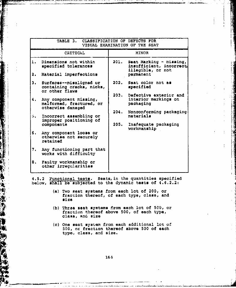
TABLE 3. CLASSIFICATION OF DEFECTS FORVISUAL EXAMINATION OF THE SEAT
SCRITICAL MINOR
1. Dimensions not within 201. Seat Marking - missing,specified tolerances insufficient, incorrecto
illegible, or not2. Material imperfections permanent
3. Surfaces--misaligned or 202. Seat color not ascontaining cracks, nicks, specifiedor other flaws
203. Defective exterior and4. Any component missing, interior markings on
malformed, fractured, or packagingotherwise damaged
204. Nonconforming packaging6. Incorrect assembling or materials
improper positioning ofcomponents 205. Inadequate packaging
workmanship6. Any component loose or
otherwise not securelyretained
7. Any functioning part thatworks with difficulty
8. Faulty workmanship orother irregularities
4.5.2 Functional tests. Seats, in the quantities specifiedbelow, shall be subjected to the dynamic tests of 4.6.2.2:
(a) Two seat systems from each lot of 200, orfraction thereof, of each type, class, andsize
(b) Three seat systems from each lot of 500, orfraction thereof above 500, of each type,class, mn6 size
(c) One seat system from each additional lot of500, or fraction thereof above 500 of eachtype, class, and size.
* 164
- ~ -- .• o • -• " ...................... •s•. .-..... •-.- -.T., - -................
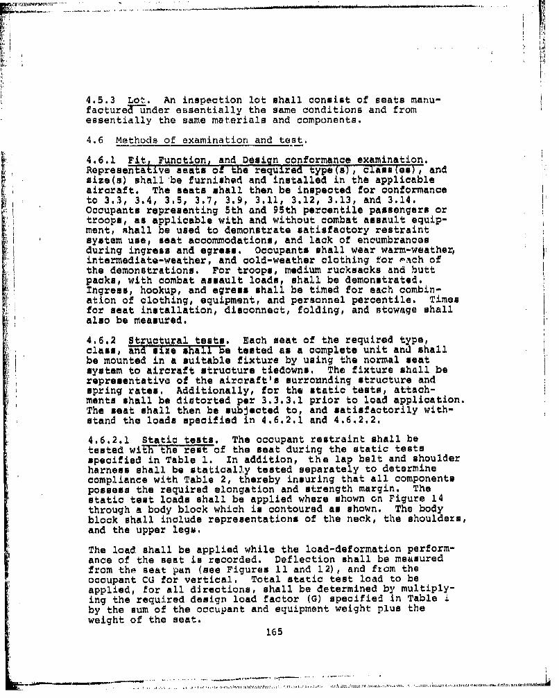
4.5.3 Lot. An inspection lot shall consist of seats manu-factureT-under essentially the same conditions and fromessentially the same materials and components.
4.6 Methods of examination and test.
4.6.1 Fit Function, and Design conformance examination.Ropresentahve seats of the required type(s), clads(es), andsize(s) shall be furnished and installed in the applicableaircraft. The seats shall then be inspected for conformanceto 3.3, 3.4, 3.5, 3.7, 3.9, 3.11, 3.12, 3.13, and 3.14.Occupants representing 5th and 95th percentile passengers ortroops, as applicable with and without combat assault equip-ment, shall be used to demonstrate satisfactory restraintsystem use, seat accommodations, and lack of encumbrancesduring ingress and egress. Occupants shall wear warm-weather, [intermediate-weather, and cold-weather clothing for Pach ofthe demonstrations. For troops, medium rucksacks and buttpacks, with combat assault loads, shall be demonstrated.Ingress, hookup, and egress shall be timed for each combin-ation of clothing, equipment, and personnel percentile. Times! ! for seat installation, disconnect, folding, and stowage shall
also be measured.
4.6.2 Structural tests. Each seat of the required type,class, and size shall be tested as a complete unit and shallbe mounted in a suitable fixture by using the normal seatsystem to aircraft structure tiedowns. The fixture shall berepresentative of the aircraft's surrounding structure andspring rates. Additionally, for the static tests, attach-ments shall be distorted per 3.3.3.1 prior to load application.The seat shall then be subjected to, and satisfactorily with-stand the loads specified in 4.6.2.1 and 4.6.2.2.
4.6.2.1 Static tests. The occupant restraint shall betested wiE' the rest of the seat during the static testsspecified in Table 1. In addition, the lap belt and shoulderharness shall be statically tested separately to determinecompliance with Table 2, thereby insuring that all componentspossess the required elongation and strength margin. Thestatic test loads shall be applied where shown on Figure 14through a body block which is contoured as shown. The bodyblock shall include representations of the neck, the shoulders,and the upper legs.
The load shall be applied while the load-deformation perform-ance of the seat is recorded. Deflection shall be measuredfrom the seat pan (see Figures 11 and 12), and ftom theoccupant CG for vertical. Total static test load to beapplied, for all directions, shall be determined by multiply-ing the required design load factor (G) specified in Table iby the sum of the occupant and equipment weight plus theweight of the seat.
165
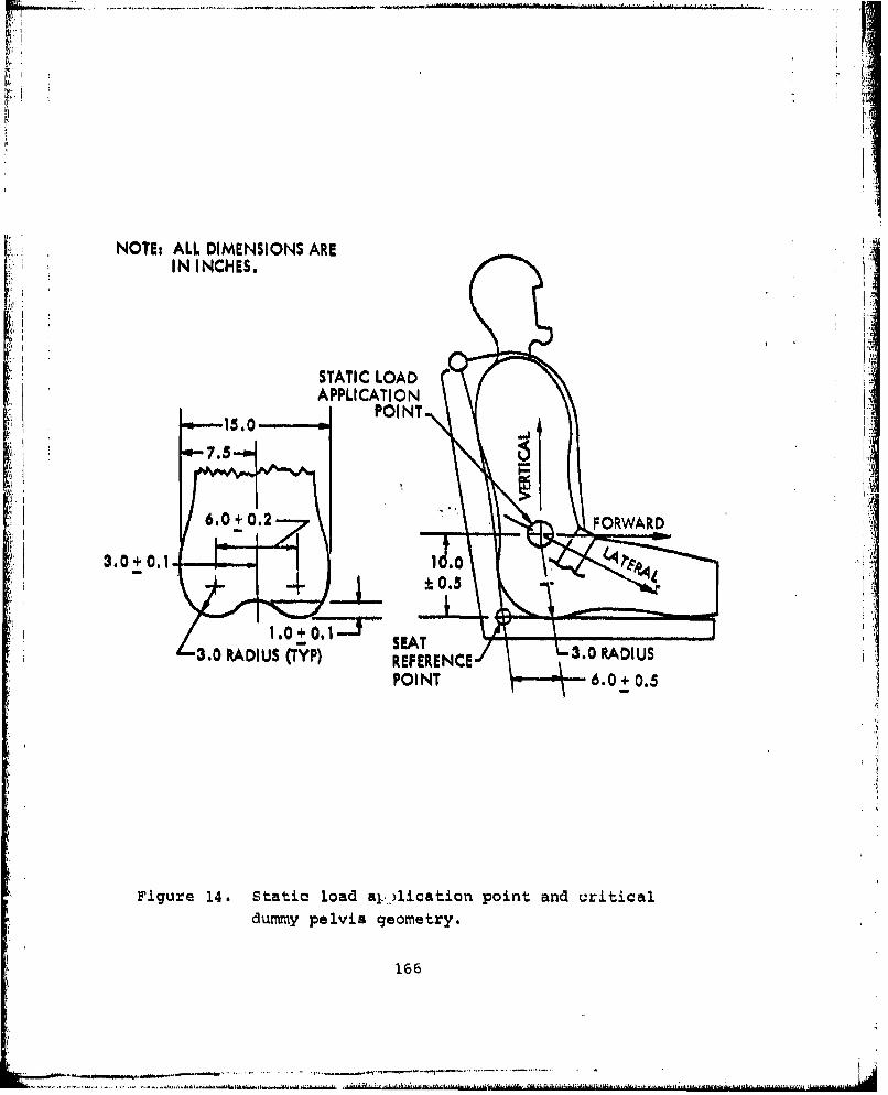
tIB
NOT~t ALL DIMENSIONS ARE
IN INCHES.
STATIC LOADAPPLICATION
15.0 POI NT ~
(I 7.5
6.0+0.2FORWARD
3.0±0.140
3.0 RADIUS (TYP) REFERENCE
Figure 14. Static load aj-,lication point, and criticaldummy pelvis geometry.
166
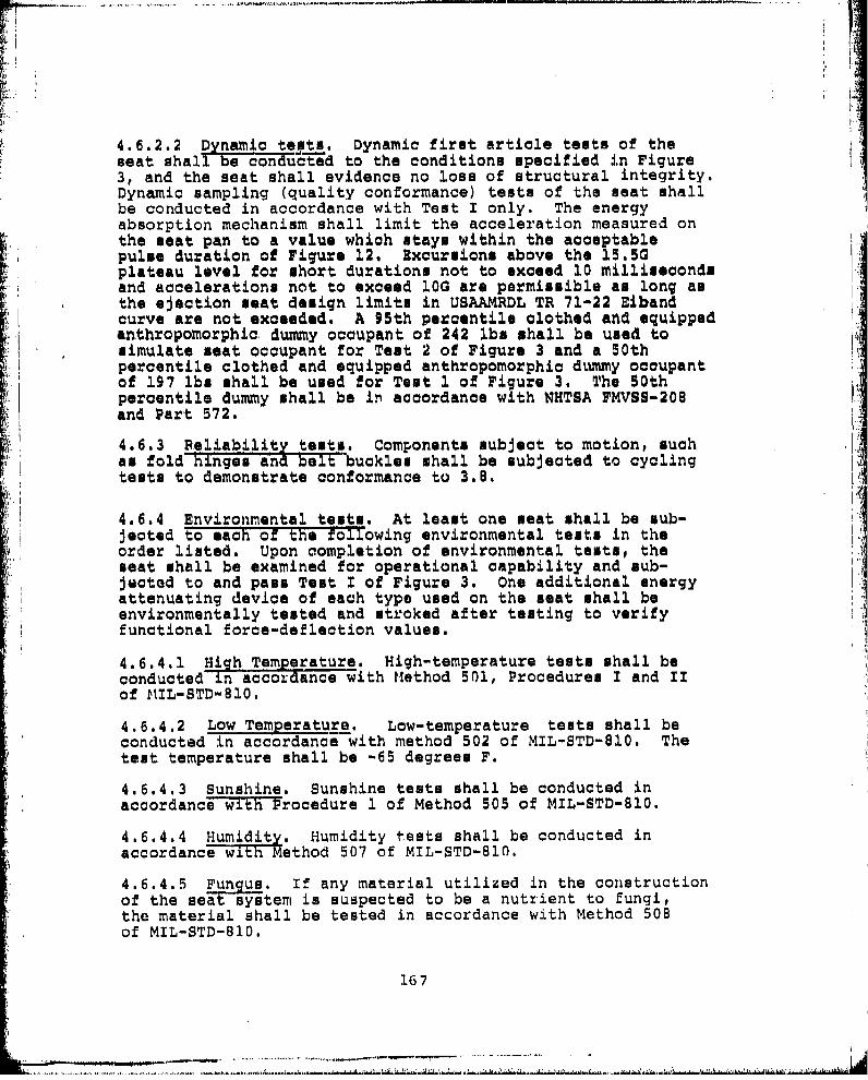
4.6.2.2 Dynamic tests. Dynamic first article tests of theseat shall be conducted to the conditions specified in Figure3, and the seat shall evidence no loss of structural integrity.Dynamic sampling (quality conformance) tests of the seat shallbe conducted in accordance with Test I only. The energyabsorption mechanism shall limit the acceleration measured onthe seat pan to a value which stays within the acceptablepulse duration of Figure 12. Excursions above the 15.50plateau level for short durations not to exceed 10 millisecondsand accelerations not to exceed lOG are permissible as long amthe ejection seat design limits in USAAMRDL TR 71-22 Elbandcurve are not exceeded. A 95th percentile clothed and equippedanthropomorphic dummy occupant of 242 lbs shall be used tosimulate seat occupant for Test 2 of Figure 3 and a 50thpercentile clothed and equipped anthropomorphic dummy occupantof 197 lbs shall be used for Test 1 of Figure 3. The 50thpercentile dummy shall be in accordance with NHTSA FMVSS-208and Part 572.
4.6.3 Reliability tests. Components subject to motion, suchan fold Finges and :ebe:uckles shall be subjected to cyclingtests to demonstrate conformance to 3.8.
4.6.4 Environmental tests. At least one seat shall be sub-Jected to each of the following environmental tests in theorder listed. Upon completion of environmental tests, theseat shall be examined for operational capability and sub-jacted to and pass Test X of Figure 3. One additional energyattenuating device of each type used on the seat shall beenvironmentally tested and stroked after testing to verifyfunctional force-deflection values.
4.6.4.1 High Temperature. High-temperature tests shall beconducted in accordance with Method 501, Procedures I and IIof MIL-STD-810.
4.6.4.2 Low Temperature. Low-temperature tests shall beconducted in accordance with method 502 of MIL-STD-810. Thetest temperature shall be -65 degrees F.
4.6.4.3 Sunshine. Sunshine tests shall be conducted inaccordance with Procedure 1 of Method 505 of MIL-STD-810.
4.6.4.4 Humidity. Humidity tests shall be conducted inaccordancWewlithMethod 507 of MIL-STD-810.
4.6.4.5 Fungu. If any material utilized in the constructionof the sea- s-stem is suspected to be a nutrient to fungi,the material shall be tested in accordance with Method 508of MIL-STD-810.
167

4.6.4.6 Salt foc. Salt fog tests shall be conducted inaccordance With Method 509 of MIL-STD-810.
4.6.4.7 Dust. The seat system shall be subjected to thedust test specified in MIL-STD-810.
4.6.4.8 Vibration. Vibration tests shall be conducted inaccordance wi-thw- -thod 514, Procedure I (parts 1, 2, and 3),of MIL-STD-810.
4.6.4.9 Mud. All mechanical joints and energy attentuatorsshall be c-oated with mud and the seat must operate beforeand after it ham dried,
5. PACKAGZN.G
5.1 Preservation and packaging. Preservation and packagingshall be level A or C, am specified (see 6.2).
5.1.1 Level A. Each seat shall be preserved and packagedin accordance with MIL-P-116, Method II, in a weather-resistant container conforming to PPP-B-636.
5.1.2 Level C. Each seat shall be preserved and packaged ina manne-thaE will afford adequate protection against corro-sion, deterioration, and physical damage during shipmentfrom the supply source to the first receiving activity for IIimmediate use. This level may conform to the supplier's Hcommercial practice, provided the latter meets the require-ments of this level,
5.2 Packing. Packing shall be level A, B, or C, as speci-fied Tseie 72).
5.2.1 Level A. Seats pveserved and packaged as specifiedin 5.1.1 shall be packed in overseas-type shipping containersconforming to PP-B-601 or PPP-B-621. As far as practicable,shipping containers shall be of uniform shape, size, andminimum cube and tare consistent with the protection required,and contain identical quantities. The gross weight of eachshipping container shall not exceed the weight limitation ofthe specification, Containers shall be closed and strappedin accordance with the above specifications and appendiciesthereto.
5.2.2 Level B. Seats preserved and packaged as specifiedin 5.1.1 shall not be overboxed for domestic shipments. Thecontainer, closed and strapped in accordance with the appli-cable appendix of the container specification, shall be theshipping container.
168
~~~~~~1~~~ . - SOO. .

5.2.3 Level C. Seats shall be packed in a manner that willafford adequate protection at the lowest rate against damnageduring direct domestic shipment from the supply source tothe first receiving activity and are destined for immediateuse at that activity. This level shall conform to applic-able carrier rules and regulations and may be the supplier'scommercial practice, provided the latter meets the require-ments of this level.
5.3 Physical protection. Cushioning, blocking, and bracingshall be in accordance with MIL-STD-1186, except for domesticshipments. Waterproofing requirements for cushioningmaterials and containers shall be waived when preservation,packaging, and packing designed for immediate use of theitem, or when drop tests of MIL-P-1l6 are applicable.
5.4 marking. Interior packages and exterior shipping con-tainers ha-l1 be marked in accordance with MIL-STD-129.
6. NOTES
6.1 Intended use. The seats covered by this specificationare intended for use by troops and passengers in helicopters,and to provide crash survival for most of these occupants inthe majority of crashes.6.2 Ordering data. Procurement documents should specifythe followingo
(a) Title, number, and date of this specification.
(b) Type, class, and size of seat required (see 1.2).
6.3 Definitions. For the purpose of this specification,the following definitions apply.
0.3.1 Anthroeometric data. U.S. Army Natick Labs Report72-51-CE hall be referred to as a source document foranthorpometric data on troops/passengers.
6.3.2 Occupant weights and equipment. Unless otherwisespecified, the occupant and equipment weights in Table 4are applicable for design and test considerations.
169
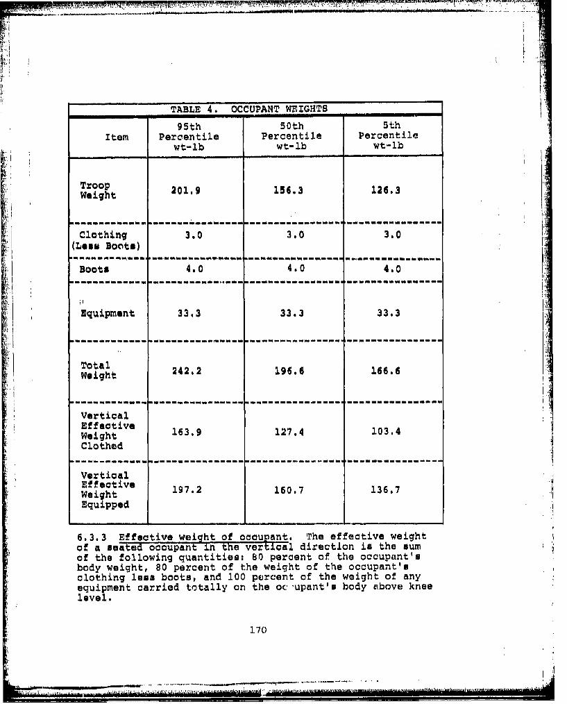
TABLE 4. OCCUPANT WEIGHTS
95th 50th SthItem Percentile Percentile Percentile
wt-lb wt-lb wt-lb
TroopWeight 201.9 156.3 126.3
Clothing 3.0 3.0 3.0(Less Boo~ts)j
Boots 4a.0 4.0 4.0
Equipment 33.3 33.3 33.3
Total24.19.16.
Weight242 9.166
Ver ti calEffective 16.124104Weight16.12.104Clothed-
VerticalEffective 19216.137Weight19.16.137Equipped
6.3.3 Effective weight of occupant. Trhe effective weightof a seated occupant in the vertlcgl direction is the sumof the following quantities: 80 percent of the occupant'sbody weight, 80 percent of the weight of the occupant'sclothing less boots, and 100 peircent of the weight of anyequipment carried totally on the oc upant'e body above kneelevel.
170
6.3.4 0. The term G is the ratio of a particular acceler-ation tF the acceleration due to gravitational attractionat sea leveli therefore, 10G represents an acceleration of321.7 feet/second/second.
6.3.5 Occupant submarining. In a crash with high verticaland longituainal forces (measured along the seat longitudinalaxis) present, the restrained body will tend to mink downinto the seat first and then almost simultaneously be forcedforward. If the seat is provided with an improperly designedrestraint or seat cushion, the inertia load of the hips andthighs will pull the lower torso under the lapbelt duringthe crash sequence. This phenomenon is referred to anoOccupant submarining.
6.3.6Dnamic oershoot. Dynamic overshoot exists when theseated occupant receives an amplification of the accelerativeforce applied to the meat. A loose or highly elastic system,or highly elastic cushion, can facilitate dynamic overshoot.
41J
A.71
172.
... ..... ..... ..... .... ....... ~ .
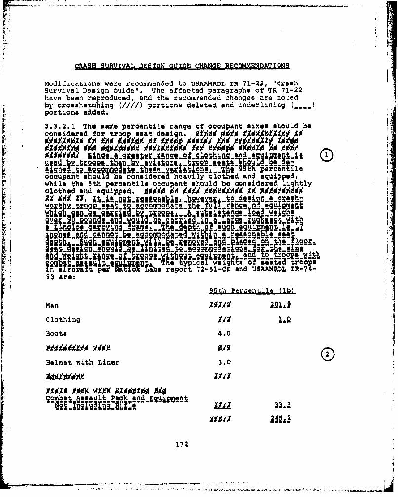
CRASH SURVIVAL DESIGN GUIDE CHANGE RECOMMENDATIONS
Modifications were recommended to USAAMRDL TR 71-22, "CrashSurvival Design Guide". The affected paragraphs of TR 71-22have been reproduced, and the recommended changes are notedby crosshatching (////) portions deleted and underlining (....)portions added.
3.3.2.1 The same percentile range of occupant sizes should beconsidered for troop seat design. 9000 004 00)(00 1Z 0
'0 t2 e j onL 9h percentlieoccupant *9houldbe con UMdere hoavi ly cothed and equipped,while the 5th percentile occupant should be considered lightlyclothed and equipped. WO $ 0 00941W XA0
woe oe o n • u men2go ca -an aal .w 22!•o•s. " M w
gve-1:2'01 a -e ruc~!azk~t
Hsg- R U02e5 INe 0a SI n ge2K 2nn weetynd.•S e w ae c
1 )r9ra2& pert•a022 ? abs repOut -51-CE an U R-74-
93 are:
95th Percentile (lb)
Man ZZ'
Clothing 0/0 9
Boots 4.0
00410Y0 0/5Helmet with Liner 3.0
Combat Assault Pack and ESijmjnt
172
* • ... . ...... .......... ..... .. . ... t.2... .; . . .... : :: . . ... . ...... ln:-fl, .ld

r
5th Percentile (1b)
Man XýZ/0 126.3
Clothing 1/0 3.0
Boots 4.0
Helmet- a!
;•, •(Revise Figure 3.23)Revise the force deflection curve of Figure 3.23B creating(Reinew figure which agrees with Figure 11 of the draft Military 03
Specif cation Seat, Helicopter, Troop and increase thestroking distance from 6 to 12 inches.
3,3.4 LATERAL STRENGTH AND DEFORMATION REQUIREMENTS
The lateral load and deformation requirements g.Zgad:.agd jag•iga•g...nga~i are presented in Figure 3-24 for the 95thpercentile accident (see Table 1-11 in Chapter 1). Two curvesare presented. One is for rotary-wing aircraft and the cock-pits of large fixed-wing aircraft. The other is for lightfixed-wing aircraft and cabins of large fixed-wing aircraft.The deflections are to be measured at the neutral seat refer-
'we noe point. Occupant weight should be a. stated in par agra h3.3.1. o € o1leda• m .Ae-laq Ang. m.abs..Me
(Revise Figure 3-24)Revise Figure 3-24 to make two figures, one for crew seatsand one for troop/passenger meats. Revise the force deflec-tion curve for troop/passenger meats to agree with Figure 2of the draft Troop Seat Military Specification and increasethe stroking distance from 4 to 6 inches.
* 3.5.2 SEAT COMPONENT ATTACHMENT
Since components that break free during a crash can becomelethal weapons, it is recommended that attachment strengthsbe consistent with those specified for ancillary equipment.Static attachment strengths for components, e.g., armoredpanels, should therefore be am followst
Downwards 35a
Upward: 15G
b'orward 35G
173
- 2-,- -- . . . .
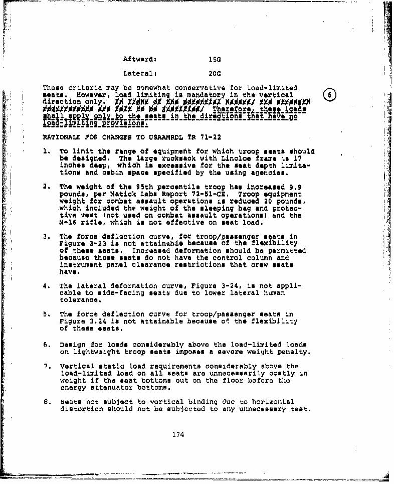
Aftward: 15G
Laterali 20G
These criteria may be somewhat conservative for load-limitedmeats. However, load limiting is mandatory in the vertical
00€ 109 0 100901001Thebrefore these loadsm ~~ - --fni
RATIONALE POP CHANGES TO USAAMPRDL TR 71-22
1. To limit the range of equipmefit for which troop seats shouldbe designed. The large rucksack with Lincloo frame is 17inches deep, which is excessive for the meat depth limita-tion. and cabin space specified by the using agencies.
2., The weight of the 95th percentile troop has increased 9.9pounds, per Natick Labs Roport 72-51-CE. Troop equipmentweight for combat assault operations is reduced 20 pounds,which included the weight of the sleeping bag and protec-tive vest (not used on combat assault operations) and the IM-16 rifle, which in not effective on seat load.
3, The force deflection curve, for troop/passenger seats inFigure 3-23 is not attainable because Of the flexibilityof theme seats, Increased deformation should be permittedbecause these seats do not have the control column andinstrument panel clearance restrictions that crew seatshave.
4, The lateral deformation curve, Figure 3-24, is not appli-cable to side-facing seats due to lower lateral humantolerance.
5. The force deflection curve for troop/passenger seats inFigure 3,24 is not attainable because ol the flexibilityof theme seats.
6. Design for loads conuiderably above the load-limited loadson lightwaight troop seats imposes a severe weight penalty.
7. Vertical static load requirements considerably above theload-limited load on all seats are unnecessarily costly inweight if the seat bottoms out on the floor before theenergy attenuator bottoms.
8. Seats not subject to vertical binding due to horizontaldistortion should not be subjercnted to any unnecessary test.
174
...........................

TABLE 3-1i. SEAT DESIGN AND OTATIC TEST REQUIREMENTS
Test Loading DirectionRef With Respect to DeformationNo. Fuselage Floor Load Required Requiremhntsa
1 Forward See Figure 3-23 See Figure 3-23
2 Aftward 120 Minimum No Requirement
3 Lateralb See Figure 3-24 See Figure 3-24 ill
4 Downward/Crew Beat 14.5 + 1.0o'~' See ParagraphTroop Seat 14.5 1 1. 0 0d 3.3.4.1
5 Upward 80 Minimum So Requirement
6 ForwardoOf See Figure 3-230 See Figure 3-23Downward/
"com- crew Seat 14 5 ± 2.0Omined Troop Seat 14.5 ±2.00 Same an Test 4
Lateralf 9G Minimum No Requirements-- r
aThe aircraft floor or sidewall should be deformed in thexz and yz planes, as detailed in paragraph 3.2.4.4 and inFigure 3-27, simultaneously with the G loads spenified.
bTho lateral loads should be applied in the direction whic?is most critical. In the case of symmetrical seats, theloading direction is optional.
Cn the event that no load-limiting device is used in theforward direction, a 20a load for cabin seats and a 25Gload for crew seats may be used for this combined loading.
d1f more than one load-limiter setting is provided, oach: should be tested.
eSubsequent to the stroking of the vertical enerry-absorbiidevice, the seat chould carry a yartigal static loadof 250, based on the effective weight of the 95th percen-tile occupant plus seat and equipment, without loss ofattachment to the basic structured" ag9Wgt..±be..eS
.afis.-reiug L Qnt1. b flQQgr Plastic deformation isacceptable in this test.
fThe forward and lateral loads should be applied prior tothe downward load application•' g s. giil im.t± [8)
175
-, --...... ..-

APPENDIX A
CRASHWORTHY TROOP SEAT TESTINGCOMPONEN'I TEST RUN
1. INTRODUCTION
The crashworthy troop seat test program includes componenttests, static test% and dynamic teats. This test plan coversthe testing of seat components which can be static testedseparately from the basic seat structure. Tests will beconducted in the instron tensile testing machine which has acapacity of 10,000 lb& The machine produces a printoutof load versus deflection.
Four component test set-ups will be made. Three of the met-ups will text a number of components in series with energyattenuators. The load, therefore, will be limited to thestroKing load of the attenuators. Ditermination of excessivedeformation of components or their failure before reachingthe stroking load will be the principal purpose of the test.Verification of the attenuators'stroking load will also beaccomplished. The fourth test setup will not include anenergy attenuator and therefore will not be load limited.The floor attachment quick diaconnect, which will be one ofthe components in the setup, will be tested to destruction.
2. STATEMENT OF WORK
Perform tensile load testing on crashworthy troop seat com-ponents as followai
Test 1 - In this test, the wire-bending energy attenua-tor used for vertical impact load limiting will betested. Also in series with the attenuator are theturnbuckle for coarse seat adjustment and the overcentertoggle latch for final meat adjustment, tensioning, andlocking. Th;se series of components will be installedin the anstron test machine by the use of adaptor platem(Figure A-l). The load will be applied in increments of300 lb, with the machine being stopped after each incre-ment and any deformation noted. Loads will be increaseduntil the energy attenuator begins stroking. Thestroking will be allowed to continue until the limit ofthe attenuator length or machine pull distance limit isreached.
176

ii
'NSTRON TESTFIXTURE 14
ADAPTER PLATE2
I l fl
~~TURN BUCKLE :TOGL LATCH
*WIRE-BENDING/ATTENUATOR
ADAPTERPLATE
Y"I INSTRON TEST
P IXTURE
1SCALE
Figure A-I. vertLctal energy attenuator tin] toggle latch testspecimen.
177

Test 2- The lateral energy-attenuator cable and frontfloor quick-disconnect fitting and stud will be thespecimens of this test. The floor attachment stud andpan fitting will be mounted in the Instron tensiletester at an angle to simulate the normal relationshipof the cable with the floor (Figure A-2). Adapters attachthe test specimen to the machine. Loads will be appliedin increments of 300 lb, with the machine beingstopped at each increment and any deformation noted. ILoads will be increased until the energy attenuatorbegins stroking. The stroking will be allowed to con-I;, tinue until the ultimate of the attenuator or the machine
-•i pull distance lin:'t is reached.
Test 3 - The longitudinal energy attenuator (E/A) andback floor quick-disconnect fitting and stud will bethe specimens of this test. The floor attachment studand pan fitting will be mounted in the instron tensiletester at an angle to simulate the normal angle of the
i attenuator strut with the floor (Figure A-3). Adaptersattach the test specimen to the machine. Loads willbe applied in increments of 300 lb, with the machinebeing stopped at each increment and any deformation noted.Loads will be increased until the E/A strut begins strok-ing. The stroking will be allowed to continue until thelimit of the E/A length or the machine pull distancelimit is reached.
Test 4 - The vertical holddown cable and back floorquick-disconnect fitting and stud will be the specimensof this test. Although the quick disconnect fitting issubject to test in Test No. 3, that test applies a pre-dominant shear load on the floor stud. Test No. 4 appliesa tension load on the stud and the loads will not belimited by an onergy attenuator. The holddown cable isof high-strength low-elongation material, and minimumelongation or stroking will be experienced. The testspecimen will be mounted in the instron test machine in amanner similar to Tests 2 and 3 (Figure A-4). Loads will
be applied in increments of 300 lb, with the machinebeing stopped at each increment and any deformation noted.Loads will be increased until failure occurs.
.....178
--..--- . . . ..

- - TNSTRON TEST FIXTURE
STUDADAPTER PLATE
LATERAL
- ~IA;
~~~ji FLOOR PANA-
A FLOOR STUD QUICK-DISCONNECT FITTING (FRONT)
TEST
SSCALE~
VlFigure A-2. Lateral energy attenuator and floor stud
quick-disconnect test specimen.
17c)
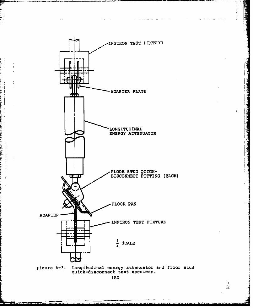
INSTRON TEST FIXTURE
~~-ADAPTER PLATE
LONGITUDINAL,ENERGY ATTENUATOR
F.oLOOR STUD QUICK-DISCONNECT FITTING (SýACK)
FLOOR PAN
ADAPTER~
INSTRON TEST FIXTURE
Figure A-?. Longitudinal energy attenuator and floor studquick-disconnect test specimen.
IS0
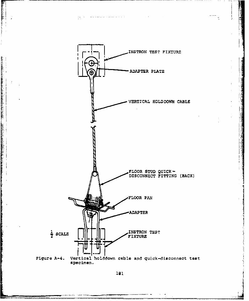
INSTRON TEST FIXTURE
I I.-
ADAPTER PLATE
V VERTICAL HOLDDOWN CABLE
FLOOR STUD QUICK-DISCONNECT FITTING (BACK)
FLOOR PAN
ADAPTER
SCLEINSTRON TEST
Figure A-4. Vertical holddown cable and quick-disconnect testspecimen.
. ...... ...... ._ _ - - - _ - - -- -- _ _ -- - - I

Tent Record - A force deflection curve printout will be L.produced for each of the four tests. The machine speedwill be set at 10 in. per minute and the paper speedset at 10 in. per minute. Still photographs will bemade for each specimen in the machine before and aftertesting. Failed parts will be disassembled and photo-graphed.
V
14
182
- .•.i .. - - _ _.. . . .. .. .. . . . . .. . . .. :... . . . .. ... ..II- -... ... . . . .. . .- . ..
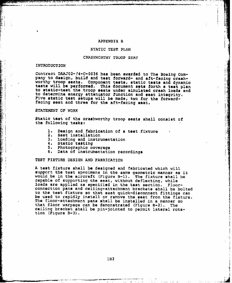
K;: 7"70 - I.! .-, :
L-11
APPENDIX B
STATIC TEST PLAN
CRASHWORTHY TROOP SEAT
INTRODUCTION
Contract DAAJ02-74-C-0036 has been awarded to The Boeing Com-pany to design, build and test forward- and aft-facing crash-worthy troop seats, Component tests, static tests and dynamictests will be performed. This document nste forth a test planto static-test the troop seats under simulated crash loads andto determine energy attenuator function and seat integrity.Five static test setups will be made, two for the forward-facing seat and three for the aft-facing seat.
STATEMENT OF WORK
Static test of the crashworthy troop seats shall consist ofthe following tasks:
i. Design and fabrication of a test fixture2. Seat installation3. Loading and instrumentation4. Static testing5. Photographic coverage6. Data of instrumentation recordings
TEST FIXTURE DESIGN AND FABRICATION
A test fixture shall be designed and fabricated which willsupport the test specimens in the same geometric manner as itwould be in the aircraft (Figure B-1). The fixture shall becapable of supporting the seat, without deflecting, whileloads are applied as specified in the test section. Floor-connection pans and ceiling-attachment brackets shall be boltedto the test fixture so that seat quick-disconnect fittings canbe used to rapidly install or remove the seat from the fixture.The floor-attachment pans shall be installed in a manner sothat floor warpage can be demonstrated (Figure B-2). Theceiling bracket shall be pin-jointed to permit lateral rota-tion (Figure B-3).
183
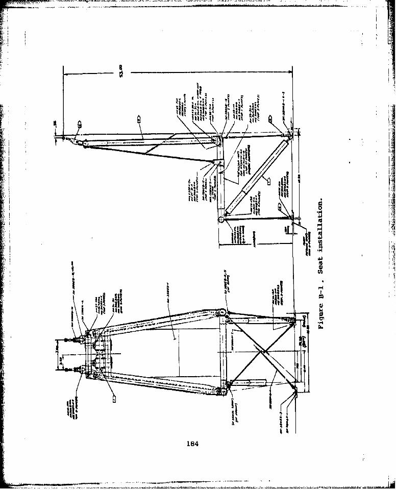
~II
1841

PPN
[TEST FIXTURE CEILING PITTING
. i i
- - - -- ....
-.. ' I 1.25 (M ,X) -
.50 DZAI
EYE .250 -
.117 DZAHOLE ~~SUGGESTED "-"STRAIN GAGE
LOCATION
SEAT TURNBUCKLECEILING CONNECTION
Note: Dimensions are in inches
Figure B-2. Ceiling connection fitting.
185
S . . . . . .. . ' . .. . -- -.. . '"

ALA
+1080
-ý --\. N4

The test fixture shall be designed to permit a minimum seatdisplacement of 12 in. laterally and 24 in. frontward or back-ward without contacting the fixture.
The same test fixture shall be adaptable for the rive testconditions. A minimum preparation shall be required to con-vert the fixture from one test condition to another.
SEAT ILISTALLATION
The seat shall be installed in the teat fixture an in the air-craft (Figure 1-1). The floor fittings and ceiling-connectionlocutions are interchangeable for forward- or aft-facing seats.The procedure for seat installation in as follows:
1. Attach turnbuckles at top of seat to ceiling brackets.2. Releaa toggle latches at turnbuckles.3. Attach quick-disconnect fittings at front of seat to
floor studs.4. Attach quick-disconnect fittings at back of seat to
floor studs.5. Close toggle latches at ceiling.6. If seat im out of adjustment, open toggle latches,
adjust turnbuckles, and close toggle latches.7. Install safety pin through toggle latch.
LOADING AND INSTRUMENTATIONThe specified load shall be applied to the body block at onepoint. Load direction specified shall not vary more than +5degrees as the seat strokes. A load cell shall be providedin the load applicator, and the output shall. be capable ofbeing, used to produce a curve showing force in pounds versusdeflection in inches. Instrumentation shall be installed onthe seat in the following locationsi
1. Strain gages on the ceiling connection fittings ofthe tout fixture (two places)(Figure B-3).
2. Tensiometer attached to one lapbelt strap.3. Tensiometer attached to both shoulder straps.4. Strain gage attached to the eyebolt at the end of the
diagonal-strut energy attenuator (two places).5. Strain gages attached to the front and back diagonal
cable fork fittings (load-carrying cable on combinedand side-loading test only).
6. Load cell attached to each side of seat at lapbeltattachment fittings and lapbelt attached to loadcells.
-8 ----------

This instrumentation shall produce a force output in poundswhich can be plotted versus deflection in inches. Strain-gaged seat components shall not be reused for subsequenttests.
STATIC TESTING
Five static tests shall be performed using a Government-furnished body block. Prior to the load application in eachtest the floor warpage proviuions shall be operated to theextent shown in Figure B-2, and shall remain in this positionfor the test. Each static test shall be performed as follows,using a new seats
Test 1 - Forward-Facinn Seat. Forward Loading
A load shall be applied at the center of gravity of thebody block, in a forward direction and parallel to thefloor. Loading shall be applied in a continuous manner.The seat shall be photographed from a fixed position atincrements during the deformation. Some stroking of theceiling attenuators at low loads is anticipated due tothe bowstring effect. As the angle of the attenuatorwith the ceiling decreases, the stroking will decreaseuntil a stable position is reached and the lower,diagonal attenuators under the seat pan begin stroking.When the lower attenuators begin stroking, loading is tobe continued until the seat pan has moved 10 in. n aforward direction. Applied load is approximately 3870lb minimum force, which is 15 a multiplied by 258 lb, the95th percentile fully-equipped troop weight plus seatweight. Force versus deflection shall be recordedduring seat stroking.
Test 2-- Forward-Facing Seat, Three-Axis Loading
The resultant of the three-axiu loading shall be appliedto the body block at the center of gravity. The angleof the resultant load shall be determined by using thefollowing load vectors,
14.5 G Downward X 177* - 2567 lb15 a Forward X 258** w 3870 lb
9 G Lateral X 258** - 2322 lb
* 50th percentile fully equipped troop affective verticalweight plus 14 lb effective seat weight.
**95th percentile fully equipped troop weight plus 14 lbeffective seat weight.
188

K
Loading shall be applied in a continuous manner. Theseat shall be photographed from a fixed position atincrements during deformation. When the loading reaches5000 lb (the approximate resultant load), loading isto be continued until the seat has stroked 10 in. inthe forward direction or has contacted the floor.Force versus deflection shall be recorded during seatstroking.
Test 3 - Aft-Fauin~q Seat,- Three-Axig Lo~adn.
"The resultant of the three-axis loading shall beapplied to the body block at the center of gravity.The angle of the resultant load shall be determinedby using the following load vectors;
14.5 G Downward X 177 - 2567 lb15 G Rearward X 258 = 3870 lb9 0 Lateral X 258 - 2322 lb
The same conditions applying to Test 2 shall applyto this test. This test shall be given the lowestpriority, due to its similarity to Test 2, and shallbe deleted in the event of failure during Test 1 orTest 2. if failure occurs in Test 1 or Teat 2, theseat designated for Test 3 shall be modified asnecessary and a retest of Teat 1 or Test 2 shall beperformed.
Test 4 - Aft-Facing Seat, Rearward Loading
A load shall be applied at the center of gravity ofthe body block, in a rearward direction of the seatand parallel to the floor. Loading shall be appliedin a continuous manner. The seat shall be photographedfrom a fixed position at increments during deformation.Some stroking of the ceiling attenuators at low loadsis anticipated due to the bowstring effect. As theangle of the attenuator with the ceiling decreases, thestroking will decrease until a stable position isreached and the lower, diagonal attenuators under theseat pan begin stroking. When the lower attenuatorsbegin stroking, loading is to be continued until themeat. pan has moved 10 in. in a rearward direction.Minimum load is approximately 3970 lb, which in 15 Gmultiplied by 258 lb, the 95th percentile fullyequipped troop weight plus seat weight. Force versusdeflection shall be recorded during seat stroking.
189
i !* * - - --

¶ I'•" --• .. .. . .. .. . ..... F . ... . . ..' " " " "..... ... . "... .- -•t•
Test 5 Aft-Facing Seat, Lateral Loading
A load shall be applied at the center of gravity ofthe body block, in a lateral direction and parallelto the floor. Loading shall be applied in a continuousmanner. The meat shall be photographed from a fixedposition at increments during the deformation. it isanticipated that the ceiling attenuators will 3trokefirst due to the bowstring effect. Stability isreached as the angle of the attenuator with the ceilingdecreases. When the lower ahtenuators begin stroking,loading is to be continued until the seat pan has movedlaterally 6 in. Minimum load is approximately 2580 ib,which is 10 a multiplied by 258 lb, the 95th percentilefully equipped troop weight plus seat weight. Forceversus deflection shall be recorded during seat strok-ing.
PHOTOGRAPHIC COVERAGP-
Photographs shall be taken before and after each test. Fivepro-test photographs shall be taken showing the complete X'.smat in the toot fixture. The photographs ,hall include afrontal, aide, rear, and three-quarter view, and a viewshowing the load applicator attachment to the body block.A minimum of four pout-test photographs shall be taken andshall include front, rear, side, and three-quarter view.Additional photographs shall be taken as necessary to showfailed components or excessive deformation. Photographsduring deformation shall be taken as appropriate.
DATA
The data output of all instrumentation used shall be pro-vided. The data shall be in the form of graphs showingforce versus deflection. Deflection shall be measured fromthe seat pan.
19 0
S... .. . ,,.

APPENDIX C
DYNAMIC TEST PLAN
CRASHWORTHY TROOP SEAT
INTRODUCTION
Contract DAAJ02-74-C-0036 has been awarded to The BoeingCompany to design, build, and test forward- and aft-facingcrashworthy troop seats. Component tests, static tests, anddynamic tests will be performed. This document sets forth atest plan to dynamic-test the troop seats under crash impact J'rconditions to detormine energy attenuation and seat integrity.Four dynamic test setups will be made, two for the forward-facing seat, and two for the aft-facing seat.
STATEMENT OF WORK
Dynamic testing of the crashworthy troop seats shall consistof the following tasks:
1. Design and fabrication of a dynamic test fixture "2. Seat installation3. Loading and instrumentation4. Dynamic testing5. Photographic coverage6. Instrumentation data acquisition
TEST FIXTURE DESIGN AND FABRICATION
A test fixture shall be designed and fabricated which willsupport the test specimens in the same geometric manner as itwould be in the aircraft (Figure C-l). The fixture shall becapable of supporting the seat, without deforming during dy-namic load application as specified in the test section.Floor-connection pans and ceiling-attachment brackets shallbe bolted to the test fixture so that seat quick-disconnectfittings can be used to rapidly install or remove the seatfrom the fixture. The ceiling bracket shall be pin-jointedto permit lateral rotation (Figure C-2).The test fixture shall be designed to permit a minimum seat
displacement of 12 in. laterally and 24 in. frontward orbackward without contacting the fixture. Adequate c. 1.earancefor dummy limb flailing shall be provided.
It is desirable that the same test fixture be adaptable forthe four test conditions. A minimum preparation shall berequired to convert the fixture from one test condition toanother.
191
___.......l -- ...... 7 .~
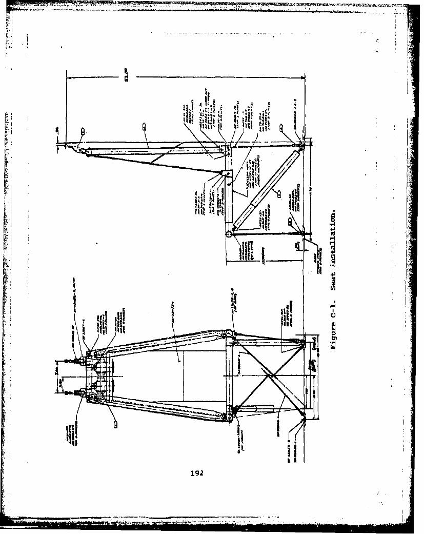
-e'XI
k,,
702
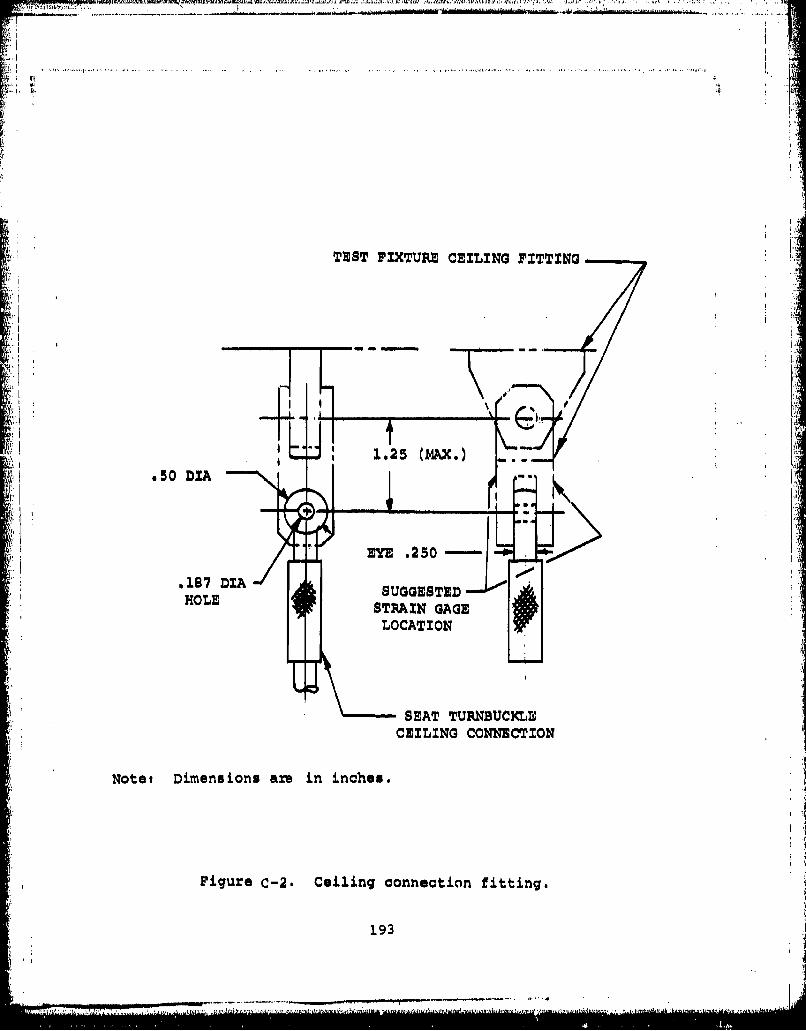
TEST FIXTURZ CEILING PITTING
W I
- ~1125 (M1AX.) -
EYE .250-
.1S7 DIASUGGESTEDHOLE STRAIN~ GAGE W
LOCATION
SEAT TURNBUCKLEDCEILING CONNEICTION
Not6t Dimensions are in inches.
Figure C-2. Ceiling connection fitting.
193
SEAT INSTALLATION
The seat shall be installed in the test fixture as in the air-craft (Figure C-1). The floor fittings and ceiling connectionlocations are interchangeable for forward- or aft-facing seats.The procedure for seat installation is as follows:
1. Attach turnbuckles at top of seat to ceiling
brackets.2. Release toggle latches at turnbuckles.3. Attach quick-disconnect fittings at front of
seat to floor studs.4. Attach quick-disconnect fittings at back of
seat to floor studs.5. Close toggle latches at ceiling.6. If seat is out of adjustment, open toggle latches,
adjust turnbuckles, and close toggle latches.7. Install safety pin through toggle latch.. K
LOADING AND INSTRUMENTATION
Each seat shall be loaded with a 95th percentile anthropomorphicdummy weighted to a total weight of 209 lb, including clothingand boots. The dummy shall be wearing a combat assault packand equipment (supplied by Boeing) which will weigh a totalof 29.8 lb.
The dummy shall be instrumented with a three-axis accelerometer.Strain gages shall be placed on test components and the testfixture as specified for each test condition, the output ofwhich shall show force in lb versus time. The accelerometeroutput shall show acceleration (G) versus time. Instrumenta-tion shall be installed in the following locations for alltests except as noted:
1. Strain gages on the ceiling connection fittingsof the test fixture, two places (Figure C-2).
2. Tensiometer attached to one lapbelt strap(Tests 1 and 2).
3. Tensiometer attached to both shoulder straps(Tests 1 and 2).
4. Strain gage attached to the eye bolt at the end ofthe diagonal-strut energy attenuator, two places(Tests 1 and 3).
5. Strain gages attached to the front and back diagonalcable fork fittings (load carrying cable)(Tests 2 and 4).
6. Accelerometer (three-axis) attached to the testfixture at floor level (two required).
7. Accelerometer (three-axis) in chest cavity of dummy.
194
I F11
DYNAMIC TESTING
Four dynamic tests shall be performed using anthropomorphicdummies with equipment. Each dynamic test shall be performedas folliws:Test 1 - Forward-Facing Seat, Downward, Forward, and Lateral
Loads
The seat shall be installed in the vertical drop test fixtureand oriented as shown in Figure C-3. A 95th percentile dummy,
k . weighted as specified and wearing combat assault equipment,
shall be placed in the seat.
The seat shall be impact tested at a vertical velocity of 50fps. A triangular impact pulse shall be produced with aduration and peak acceleration as shown in Figure C-3.
Test 2 - Forward-Facing Seat, Forward, and Lateral Loads
The seat shall be installed in the horizontal acceleiator testfixture and oriented as shown in Figure C-4. A 95th percentiledummy, weighted as specified and wearing combat assault equip-ment, shall be placed in the seat.
The seat system shall be impact tested at a horizontal velocityof 50 fps. A triangular impact pulse shall be produced with aduration and peak acceleration as shown in Figure C-4.
Test 3 - Aft-Facing Seat, Downward, Forward, and Lateral Loads
The seat shall be installed in the vertical drop test fixtureand oriented as shown in Figure C-5. A 95th percentile dummy,weighted as specified and wearing combat assault equipment,shall be placed in the seat.
The seat system shall be impact tested at a vertical velocityof 50 fps. A triangular impact pulse shall be produced with
a duration and peak acceleration as shown in Figure C-5.
Test 4 - Aft-Facing Seat, Forward, and Lateral Loads
The seat shall be installed in the horizontal accelerator testfixture and oriented as shown in Figure C-6. A 95th percentiledummy, weighted as specified and wearing combat assault equip-ment, shall be placed in the seat,
The seat system shall be impact tested at a horizontal velocityof 50 fps. A triangular impact pulse shall be produced with aduration and peak acceleration as shown in Figure C-6.
195

TEST 1DOWNWARD, FORWARD, AND
LATERAL LOADSrDUMMY INERTIXA
LOAD
3 V II0
-48G
AV 50 FPS
ý40.065 SEC
PEAK.O PAK G-The rise tim~e forthe triangularpulses may vary TIME TIMEbetween the two o-0.4t0values illustrated. ,8
Figure C-3. Impact pulse and seat orientation, test 1.
196

FORWARD ANDLM LLAS !
/ DUMMYINERTIA
LOAD
-24GAV" 50 FPS
S4-0.130 SEC
The rise time forthe triangularpulses may vary TIME TIMEbetween the two --•0 . 4 t, 0.tvalues illustrated. t
Figure C-4. ImpaCt pulse and seat orientation, test 2.
197

TEST 3DOWNWARD, FORWARD, AND17 LATERAL LOADS
DUMMY INERTIA-~LOAD
300
Ix
-- 48G
A~V -50 FPS
0.065 $EC
-PEAK.G PEAK 0
The rise time forthe triangularTIEIMpulses may varyTMETM"between the two 4 .values illustrated.
Figure C-5. Impact pulse and seat orientation, test 3.
198
i.",

TEST 4
FORWARD AND LATERAL LOADS
LOAD
-24G
AV 50 FPS
0.130 SEC
H-PEAX, G PEAKThe rise time forthe triangularpulses may vary TIME TIMEbetwoon the two -0-,4.4t 0 .values illustrated,
Figure C-6. Impact pulse and seat orientation, test 4.
199

PHOTOGRAPHIC COVERAGE
Photographs shall be taken before and after each test. Fourpre-test photographs shall be taken showing the complete seatin the test fixture. The photographs shall include a frontal,side, rear, and three-quarter view. A minimum of four post-test photographs shall be taken and shall include frontal,rear, side, and three-quarter view. Additional photographsshall be taken as necessary to show failed components ordeformation.
High-speed uolor motion pictures (400 frames per second) shallbe mode of each dynamic test. Three cameras shall be usedproviding full coverage of the front, back, and side of eachseat. Redundant cameras shall be used for front and sidecoverage.
DATA
The data output of all instrumentation used shall be provided.The data shall be in the form of graphs showing force versustime or acceleration versus time. Deflection of attenuatorsshall be measured after each test. Test data shall be dis-played in a form showing the degree of compliance with thedynamic test criteria, paragraph 4.5.3.2 of the draft MilitarySpecification, Seat, Helicopter, Troop (USAAMRDL-TR-74-93).
200 I.•7•-77I:.i

MI~ If91M
flWS~co ffai' 8*96P.
(Fo IIAG40i
/ ~201.
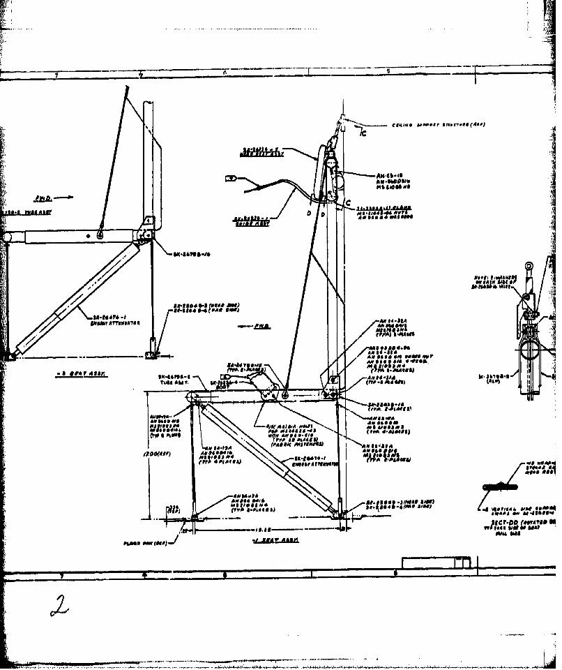
.... .... ...
JB
AN 0 00 10S0'0b 0
gemv A~tUIMIA
I'll's (4111-411=11.w 211
1' ~ ~ wf AM~~u. to, ubclo
A'-~AM ad& ARso
rmman
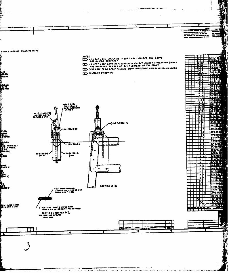
CD !4 1~ 111:z1
CD~e SIO* Sfr~III AM SV9#P W 440I(I'4Y IF#P~flWV
3> E 1167141"T byy DAA54iA 1511 A do
Ab A,
A.,'4
a~t"**4 will I 5.4
~.t~o 3.l&* * a-iS
I W *4~
4 u4ts.Sea.
fee) (SP4I (!
on WI 041-T-L
+ r .,T a
bfS) I .1to
-- F lilt
#*a 45? AsirJ4I1 ~j'ii3 16SSMc?.v sonV8 ~
joac) Z.4. tA4IS& AWRPPg0
80fdo 6, N-alve-#F~me -ou
WSO war
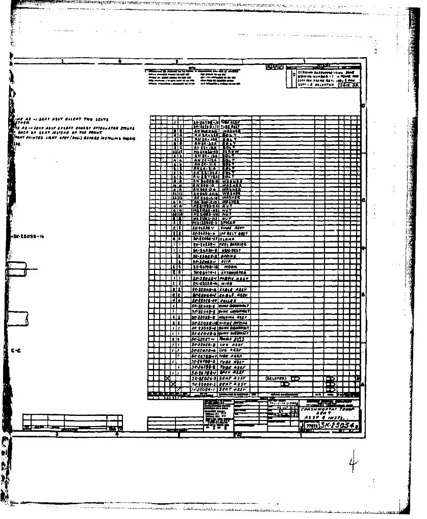
'".Waamia4 t
I A i- i~ .1 4114F A hlloy BA e9 aev jtop@ l ro a IJL - L I
'AV 0AI-dT8A dMMP 41PIV 061A) SiIM4 0*11044*6 A4041 A A
.Al a 'e a4 4, NICL *4IEa & AN b &A- 11
AL a
C.'A
5IX111 Ow" IAgar8314*611- LAO810$00
"CaLKIO.5II F t6A6101Rb