
RASHMI VT REPORT
34
A Report on Vocational Training In “IPV6” Submitted in partial fulfillment of requirement for the award of degree Of Bachelor of Engineering In “Electronics and Telecommunications” To Chhattisgarh Swami Vivekanand Technical University, Bhilai In Session: 2013-2014 Submitted By: Rashmi Kumari 7TH/ETC 1
-
Upload
rashmi-kumari -
Category
Documents
-
view
193 -
download
0
Transcript of RASHMI VT REPORT

A
Report on Vocational Training
In
“IPV6”
Submitted in partial fulfillment of requirement for the award of degree
Of
Bachelor of Engineering
In
“Electronics and Telecommunications”
To
Chhattisgarh Swami Vivekanand Technical University, Bhilai
In Session: 2013-2014
Submitted By:
Rashmi Kumari
7TH/ETC
1

A C K N O W L E D G E M E N T
I have completed my vocational training on routing and switching from Rooman Technologies and I
am thankful to the trainers. Especially to Mr. Ajit Singh for providing us valuable knowledge and
information about the”RoutingAndSwitching”. I extend my thanks to respected Mr. KSHITIJ
SINGHAI (Director) for his support, encouragement and facilitation. I highly thankful to”ROOMAN
TECHNOLOGIES” for their valuable guidance that they shared with us through our project during
the training session.
I also Grateful to Mr. AJAY PRAKASH VERMA (Chairman) ,Dr. ANURAG VERMA (Director)
and Dr. MAHESH P. (Principal) for their support & permission for the training. I also thankful to
Dr. AMIT AGRAWAL (professor & H.O.D Electronics & Telecommunication Department) for
the valuable guidance.
I express my sincere gratitude to all the faculty members and supporting staff members of Electronics
& Telecommunication Engineering Department.
(Signature of the Student)
Rashmi Kumari
CHHATRAPATI SHIVAJI INSTITUTE OF TECHNOLOGY, DURG
Shivaji Nagar, Balod Road, Kolihapuri, Post Pisegaon – Durg
(C.G.) 491001
2
CERTIFICATE
This is to certify that Shri/Ku Rashmi Kumari Roll No. 50 Semester 7th Branch Electronics
& Telecommunications student of Chhatrapati Shivaji Institute of Technology, Durg has
undergone his/her Vocational Training on Routers & Switches at ROOMAN Technologie
From July To August
Mr. Rahul Sinha Dr. Amit Agrawal
Assistant Professor Professor & Head
Department of Elex.& Telecom. Department of Elex.& Telecom.
Date:18/09/2014
Place: Durg
3

Table of Contents
Sr. No. Topic Page No.
1 Introduction 5
1.1 Comparison with IPV4 6
2
3
3.1
3.2
3.3
4
5
6
7
8
9
Packet format
Addressing
Link local address
Address representation
Create a global address
OSPF
Area Types
Implementing OSPF for IPv6
Result
Conclusion
References
10
11
11
11
12
13
16
18
21
23
23
4
1. Introduction
IPv6 is one of the most significant network and technology upgrades in history. It will slowly
grow into your existing IPv4 infrastructure and positively impact your network. Reading this
book will prepare you for the next step of networking technology evolution. IPv6 product
development and implementation efforts are already underway all over the world. IPv6 is
designed as an evolutionary step from IPv4. It is a natural increment to IPv4, can be installed
as a normal software upgrade in most Internet devices, and is interoperable with the current
IPv4. IPv6 is designed to run well on high performance networks like Gigabit Ethernet, ATM,
and others, as well as low bandwidth networks (e.g., wireless). In addition, it provides a
platform for new Internet functionality that will be required in the near future, such as
extended addressing, better security, and quality of service (QoS) features.
IPv6 includes transition and interoperability mechanisms that are designed to allow users to
adopt and deploy IPv6 step by step as needed and to provide direct interoperability between
IPv4 and IPv6 hosts. The transition to a new version of the Internet Protocol (IP) must be
incremental, with few or no critical interdependencies, if it is to succeed. The IPv6 transition
allows users to upgrade their hosts to IPv6 and network operators to deploy IPv6 in routers
with very little coordination between the two groups.
The rapid growth of IP devices today have led to a shortage of IP addresses. IPv6 will solve
this problem, along with some other improvements as well. It is important to understand the
fundamentals of IPv6 and how to configure complex and well working networks with this
new protocol. How to make the transition from IPv4 to IPv6 in a network can be made with
different solutions. The authors of this report have, in the network simulation tool GNS3, built
a network consisting of four routers running both IPv4 and IPv6, using dual stack as the
transition method. The reason for choosing dual stack is to simulate a situation where a
network wants to be prepared for the future transition to IPv6, while still maintaining the
function of the current IPv4 network. The routing protocol used is OSPF version 2 and 3,
using multiple areas and virtual links. The network also includes a DHCP server which
distributes IPv4 addresses to nodes connected to the four different routers. The nodes are
simulated using Microsoft loopback adapters. The reason for using GNS3 simulation program
is that you can run the real router images in it, meaning that the results are exactly the same as
with real equipment.
5

1.1 Comparison with IPV4
On the Internet, data is transmitted in the form of network packets. IPv6 specifies a
new packet format, designed to minimize packet header processing by routers. Because the
headers of IPv4 packets and IPv6 packets are significantly different, the two protocols are not
interoperable. However, in most respects, IPv6 is a conservative extension of IPv4. Most
transport and application-layer protocols need little or no change to operate over IPv6;
exceptions are application protocols that embed internet-layer addresses, such as FTP
and NTPv3, where the new address format may cause conflicts with existing protocol syntax.
1.1.1 Larger address space
The main advantage of IPv6 over IPv4 is its larger address space. The length of an IPv6
address is 128 bits, compared with 32 bits in IPv4. The address space therefore has 2128or
approximately 3.4×1038 addresses. This would be about 100 addresses for every atom on the
surface of the earth and almost four /64s per square centimetre of the planet. In addition, the
IPv4 address space is poorly allocated, with approximately 14% of all available addresses
utilized. While these numbers are large, it was not the intent of the designers of the IPv6
address space to assure geographical saturation with usable addresses. Rather, the longer
addresses simplify allocation of addresses, enable efficient route aggregation, and allow
implementation of special addressing features. In IPv4, complex Classless Inter-Domain
Routing (CIDR) methods were developed to make the best use of the small address space.
The standard size of a subnet in IPv6 is 264 addresses, the square of the size of the entire IPv4
address space. Thus, actual address space utilization rates will be small in IPv6, but network
management and routing efficiency is improved by the large subnet space and hierarchical
route aggregation. Renumbering an existing network for a new connectivity provider with
different routing prefixes is a major effort with IPv4. With IPv6, however, changing the prefix
announced by a few routers can in principle renumber an entire network, since the host
identifiers (the least-significant 64 bits of an address) can be independently self-configured by
a host
1.1.2 Multicasting
Multicasting, the transmission of a packet to multiple destinations in a single send operation,
is part of the base specification in IPv6. In IPv4 this is an optional although commonly
implemented feature. IPv6 multicast addressing shares common features and protocols with
6

IPv4 multicast, but also provides changes and improvements by eliminating the need for
certain protocols. IPv6 does not implement traditional IP broadcast, i.e. the transmission of a
packet to all hosts on the attached link using a special broadcast address, and therefore does
not define broadcast addresses. In IPv6, the same result can be achieved by sending a packet
to the link-local all nodes multicast group at address ff02::1 , which is analogous to IPv4
multicast to address 224.0.0.1 . IPv6 also provides for new multicast implementations,
including embedding rendezvous point addresses in an IPv6 multicast group address, which
simplifies the deployment of inter-domain solutions In IPv4 it is very difficult for an
organization to get even one globally routable multicast group assignment, and the
implementation of inter-domain solutions is arcane. Unicast address assignments by a local
Internet registry for IPv6 have at least a 64-bit routing prefix, yielding the smallest subnet size
available in IPv6 (also 64 bits). With such an assignment it is possible to embed the unicast
address prefix into the IPv6 multicast address format, while still providing a 32-bit block, the
least significant bits of the address, or approximately 4.2 billion multicast group identifiers.
Thus each user of an IPv6 subnet automatically has available a set of globally routable source-
specific multicast groups for multicast applications
1.1.3 Network-layer security
Internet Protocol Security (IPsec) was originally developed for IPv6, but found widespread
deployment first in IPv4, for which it was re-engineered. IPsec was a mandatory specification
of the base IPv6 protocol suite, but has since been made optional
Simplified processing by routers :-
In IPv6, the packet header and the process of packet forwarding have been simplified.
Although IPv6 packet headers are at least twice the size of IPv4 packet headers, packet
processing by routers is generally more efficient, thereby extending the end-to-end
principle of Internet design. Specifically:
The packet header in IPv6 is simpler than that used in IPv4, with many rarely used fields
moved to separate optional header extensions.
IPv6 routers do not perform fragmentation. IPv6 hosts are required to either perform path
MTU discovery, perform end-to-end fragmentation, or to send packets no larger than the
IPv6 default MTU size of 1280 octets.
7

The IPv6 header is not protected by a checksum; integrity protection is assumed to be
assured by both link-layer and higher-layer (TCP, UDP, etc.) error detection. UDP/IPv4
may actually have a checksum of 0, indicating no checksum; IPv6 requires UDP to have
its own checksum. Therefore, IPv6 routers do not need to recomputed a checksum when
header fields (such as the time to live (TTL) or hop count) change. This improvement
may have been made less necessary by the development of routers that perform checksum
computation at link speed using dedicated hardware, but it is still relevant for software-
based routers.
The TTL field of IPv4 has been renamed to Hop Limit in IPv6, reflecting the fact that
routers are no longer expected to compute the time a packet has spent in a queue.
1.1.4 Mobility
Unlike mobile IPv4, mobile IPv6 avoids triangular routing and is therefore as efficient as
native IPv6. IPv6 routers may also allow entire subnets to move to a new router connection
point without renumbering.
1.1.5 Privacy
Like IPv4, IPv6 supports globally unique IP addresses by which the network activity of each
device can potentially be tracked. The design of IPv6 intended to re-emphasize the end-to-end
principle of network design that was originally conceived during the establishment of the
early Internet. In this approach each device on the network has a unique address globally
reachable directly from any other location on the Internet.
Network prefix
Network prefix tracking is less of a concern if the user's ISP assigns a dynamic
network prefix via DHCP. Privacy extensions do little to protect the user from
tracking if the ISP assigns a static network prefix. In this scenario, the network prefix
is the unique identifier for tracking and the Interface identifier is secondary.
Interface identifier
In IPv4 the effort to conserve address space with network address translation (NAT)
obfuscates network address spaces, hosts, and topologies. In IPv6 when using address
auto-configuration, the Interface Identifier (MAC address) of an interface port is used
to make its public IP address unique, exposing the type of hardware used and
providing a unique handle for a user's online activity. It is not a requirement for IPv6
8

hosts to use address auto-configuration, however. Yet, even when an address is not
based on the MAC address, the interface's address is globally unique, in contrast to
NAT-masqueraded private networks. Privacy extensions for IPv6 have been defined to
address these privacy concerns, although Silvia Hagen describes these as being largely
due to "misunderstanding". When privacy extensions are enabled, the operating
system generates random host identifiers to combine with the assigned network prefix.
These ephemeral addresses are used to communicate with remote hosts making it
more difficult to track a single device. Privacy extensions are enabled by default in
Windows (since XP SP1), OS X (since 10.7), and iOS (since version 4.3). Some Linux
distributions have enabled privacy extensions as well. Privacy extensions do not
protect the user from other forms of activity tracking, such as tracking
cookies or browser fingerprinting.
1.1.6 Options extensibility
The IPv6 packet header has a fixed size (40 octets). Options are implemented as additional
extension headers after the IPv6 header, which limits their size only by the size of an entire
packet. The extension header mechanism makes the protocol extensible in that it allows future
services for quality of service, security, mobility, and others to be added without redesign of
the basic protocol.
1.1.7 Jumbo grams
IPv4 limits packets to 65535 (216−1) octets of payload. An IPv6 node can optionally handle
packets over this limit, referred to as jumbo grams, which can be as large
as4294967295 (232−1) octets. The use of jumbo grams may improve performance over high-
MTU links. The use of jumbo grams is indicated by the Jumbo Payload Option header.
9

2. Packet Format
An IPv6 packet has two parts: a header and payload. The header consists of a fixed portion
with minimal functionality required for all packets and may be followed by optional
extensions to implement special features. The fixed header occupies the first 40 octets (320
bits) of the IPv6 packet. It contains the source and destination addresses, traffic classification
options, a hop counter, and the type of the optional extension or payload which follows the
header. This Next Header field tells the receiver how to interpret the data which follows the
header. If the packet contains options, this field contains the option type of the next option.
The "Next Header" field of the last option, points to the upper-layer protocol that is carried in
the packet's payload. Extension headers carry options that are used for special treatment of a
packet in the network, e.g., for routing, fragmentation, and for security using
the IPsec framework. Without special options, a payload must be less than 64KB. With a
Jumbo Payload option (in a Hop-By-Hop Options extension header), the payload must be less
than 4 GB. Unlike for IPv4, routers never fragment a packet. Hosts are expected to use Path
MTU Discovery to make their packets small enough to reach the destination without needing
to be fragmented. See IPv6 packet fragmentation.
10

3. Addressing
Compared to IPv4, the most obvious advantage of IPv6 is its larger address space. IPv4
addresses are 32 bits long and number about 4.3×10⁹ (4.3 billion). IPv6 addresses are 128 bits
long and number about 3.4×1038 (340 undecillion). IPv6's addresses are deemed enough for
the foreseeable future. IPv6 addresses are written in eight groups of four hexadecimal digits
separated by colons, such as 2001:0db8:85a3:0000:0000:8a2e:0370:7334 . IPv6 unicast
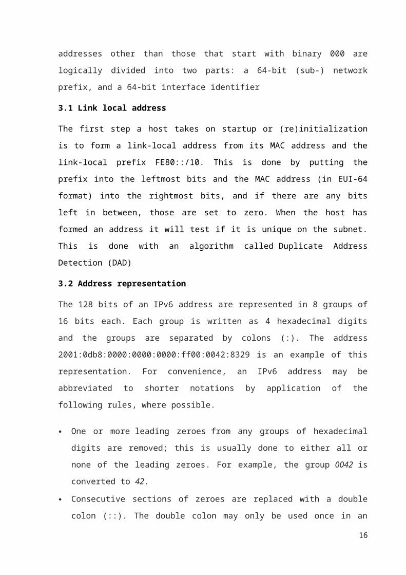
addresses other than those that start with binary 000 are logically divided into two parts: a 64-
bit (sub-) network prefix, and a 64-bit interface identifier
3.1 Link local address
The first step a host takes on startup or (re)initialization is to form a link-local address from its
MAC address and the link-local prefix FE80::/10. This is done by putting the prefix into the
leftmost bits and the MAC address (in EUI-64 format) into the rightmost bits, and if there are
any bits left in between, those are set to zero. When the host has formed an address it will test
if it is unique on the subnet. This is done with an algorithm called Duplicate Address
Detection (DAD)
3.2 Address representation
The 128 bits of an IPv6 address are represented in 8 groups of 16 bits each. Each group is
written as 4 hexadecimal digits and the groups are separated by colons (:). The address
2001:0db8:0000:0000:0000:ff00:0042:8329 is an example of this representation. For
convenience, an IPv6 address may be abbreviated to shorter notations by application of the
following rules, where possible.
One or more leading zeroes from any groups of hexadecimal digits are removed; this is
usually done to either all or none of the leading zeroes. For example, the group 0042 is
converted to 42.
Consecutive sections of zeroes are replaced with a double colon (::). The double colon
may only be used once in an address, as multiple use would render the address
indeterminate. RFC 5952 recommends that a double colon must not be used to denote an
omitted single section of zeroes.
11

An example of application of these rules:
Initial address: 2001:0db8:0000:0000:0000:ff00:0042:8329
After removing all leading zeroes: 2001:db8:0:0:0:ff00:42:8329
After omitting consecutive sections of zeroes: 2001:db8::ff00:42:8329
The loopback address, 0000:0000:0000:0000:0000:0000:0000:0001, may be abbreviated
to ::1 by using both rules. As an IPv6 address may have more than one representation, the
IETF has issued a proposed standard for representing them in text
3.3 Create a global address
This is done in the same fashion as the link-local address, but instead of the link-local prefix
FE80:: it will use the prefix supplied by the router and put it together with its identifier (which
by default is the MAC address in EUI-64 format). There is no need to perform a DAD check
because the identifier is already unique on the link, and the subnet prefix specifies a specific
link. If the information from the router contained several subnet prefixes, the host will create
one address for each one. For stateless address autoconfiguration (SLAAC) to work, subnets
require a /64 address block, as defined in RFC 4291 section 2.5.1. Local Internet registries get
assigned at least /32 blocks, which they divide among ISPs. The obsolete RFC
3177 recommended the assignment of a /48 to end-consumer sites. This was replaced by RFC
6177, which "recommends giving home sites significantly more than a single /64, but does not
recommend that every home site be given a /48 either". /56s are specifically considered. It
remains to be seen if ISPs will honor this recommendation. For example, during initial
trials, Comcast customers were given a single /64 network. IPv6 addresses are classified by
three types of networking methodologies: unicast addresses identify each network
interface, anycast addresses identify a group of interfaces, usually at different locations of
which the nearest one is automatically selected, and multicast addresses are used to deliver
one packet to many interfaces. The broadcast method is not implemented in IPv6. Each IPv6
address has a scope, which specifies in which part of the network it is valid and unique. Some
addresses are unique only on the local (sub-)network. Others are globally unique. Some IPv6
addresses are reserved for special purposes, such as loopback, 6to4 tunneling, and Teredo
tunneling, as outlined in RFC 5156. Also, some address ranges are considered special, such as
link-local addresses for use on the local link only, Unique Local addresses (ULA), as
12
described in RFC 4193, and solicited-node multicast addresses used in the Neighbor
Discovery Protocol.
4. OSPF
Open Shortest Path First (OSPF) is a routing protocol for Internet Protocol (IP) networks. It
uses a link state routing algorithm and falls into the group of interior routing protocols,
operating within a single autonomous system (AS). It is defined as OSPF Version 2 in RFC
2328 (1998) for IPv4. The updates for IPv6 are specified as OSPF Version 3 in RFC
5340 (2008). OSPF is perhaps the most widely used interior gateway protocol (IGP) in large
enterprise networks. IS-IS, another link-state dynamic routing protocol, is more common in
large service provider networks. The most widely used exterior gateway protocol is
the Border Gateway Protocol (BGP), the principal routing protocol between autonomous
systems on the Internet. IPv6 supports many routing protocols, one of which is Open Shortest
Path First (OSPF). OSPF is a link-state routing protocol, which means that every router in the
area has the same link-state database. The database contains the paths to every other router in
the area. The information stored in the database is received from advertisements that are sent
over the network. Using Dijkstra's algorithm, the shortest path to different destinations is then
calculated on each router from the information in the database. The shortest path is stored in
the routing table. The new version of OSPF, version 3, is based on OSPFv2 that runs over
IPv4. Some similarities exist between the two versions, but some changes had to be made to
support the increased address space in IPv6 and other changes in the protocol. OSPF is
an interior gateway protocol (IGP) for routing Internet Protocol (IP) packets solely within a
single routing domain, such as an autonomous system. It gathers link state information from
available routers and constructs a topology map of the network. The topology is presented as
a routing table to the Internet Layer which routes datagrams based solely on the destination IP
address found in IP packets. OSPF supports Internet Protocol Version 4 (IPv4) and Internet
Protocol Version 6 (IPv6) networks and features variable-length subnet masking (VLSM)
and Classless Inter-Domain Routing (CIDR) addressing models. OSPF detects changes in the
topology, such as link failures, and converges on a new loop-free routing structure within
seconds. It computes the shortest path tree for each route using a method based on Dijkstra's
algorithm, a shortest path first algorithm. The OSPF routing policies for constructing a route
table are governed by link cost factors (external metrics) associated with each routing
interface. Cost factors may be the distance of a router (round-trip time), data throughput of a
link, or link availability and reliability, expressed as simple unitless numbers. This provides a
13

dynamic process of traffic load balancing between routes of equal cost. An OSPF network
may be structured, or subdivided, into routing areas to simplify administration and optimize
traffic and resource utilization. Areas are identified by 32-bit numbers, expressed either
simply in decimal, or often in octet-based dot-decimal notation, familiar from IPv4 address
notation. By convention, area 0 (zero), or 0.0.0.0, represents the core or backbone area of an
OSPF network. The identifications of other areas may be chosen at will; often, administrators
select the IP address of a main router in an area as area identification. Each additional area
must have a direct or virtual connection to the OSPF backbone area. Such connections are
maintained by an interconnecting router, known as area border router (ABR). An ABR
maintains separate link state databases for each area it serves and maintains summarized
routes for all areas in the network. OSPF does not use a TCP/IP transport protocol, such as
UDP or TCP, but encapsulates its data in IP datagrams with protocol number 89. This is in
contrast to other routing protocols, such as the Routing Information Protocol (RIP) and
the Border Gateway Protocol (BGP). OSPF implements its own error detection and correction
functions. OSPF uses multicast addressing for route flooding on a broadcast domain. For non-
broadcast networks, special provisions for configuration facilitate neighbor discovery. OSPF
multicast IP packets never traverse IP routers (never traverse Broadcast Domains), they never
travel more than one hop. OSPF is therefor a Link Layer protocol in the Internet Protocol
Suite. OSPF reserves the multicast addresses 224.0.0.5 (IPv4) and FF02::5 (IPv6) for all
SPF/link state routers (AllSPFRouters) and 224.0.0.6 (IPv4) and FF02::6 (IPv6) for all
Designated Routers (AllDRouters), as specified in RFC 2328 and RFC 5340. For routing
multicast IP traffic, OSPF supports the Multicast Open Shortest Path First protocol (MOSPF)
as defined in RFC 1584. Cisco does not include MOSPF in their OSPF implementations. PIM
(Protocol Independent Multicast) in conjunction with OSPF or other IGPs, is widely
deployed. The OSPF protocol, when running on IPv4, can operate securely between routers,
optionally using a variety of authentication methods to allow only trusted routers to
participate in routing. OSPFv3, running on IPv6, no longer supports protocol-internal
authentication. Instead, it relies on IPv6 protocol security (IPsec). OSPF version 3 introduces
modifications to the IPv4 implementation of the protocol. Except for virtual links, all
neighbor exchanges use IPv6 link-local addressing exclusively. The IPv6 protocol runs per
link, rather than based on the subnet. All IP prefix information has been removed from the
link-state advertisements and from the Hello discovery packet making OSPFv3 essentially
protocol-independent. Despite the expanded IP addressing to 128-bits in IPv6, area and router
Identifications are still based on 32-bit values.
14
4.1 Router Relationships
OSPF supports complex networks with multiple routers, including backup routers, to balance
traffic load on multiple links to other subnetworks. Neighboring routers in the samebroadcast
domain or at each end of a point-to-point telecommunications communicate with each other
via the OSPF protocol. Routers form adjacencies when they have detected each other. This
detection is initiated when a router identifies itself in a Hello protocol packet. Upon
acknowledgment, this establishes a two-way state and is the most basic relationship. The
routers in an Ethernet or Frame Relay network select a Designated Router (DR) and a Backup
Designated Router (BDR) which act as a hub to reduce traffic between routers. OSPF uses
both unicast and multicast transmission modes to send "Hello" packets and link state updates.
As a link state routing protocol, OSPF establishes and maintains neighbor relationships for
exchanging routing updates with other routers. The neighbor relationship table is called
anadjacency database. An OSPF router forms neighbor relationships only with the routers
directly connected to it. For forming a neighbor relationship between, the interfaces used to
form the relationship must be in the same OSPF area. Generally an interface is only
configured in a single area, however, an interface may be configured to belong to multiple
areas. In the second area, such an interface must be configured as a secondary interface.
15
5. Area Types
An OSPF network is divided into areas that are logical groupings of hosts and networks. An
area includes its router having interfaces connected to the network. Each area maintains a
separate link state database whose information may be summarized towards the rest of the
network by the connecting router. Thus, the topology of an area is unknown outside of the
area. This reduces the routing traffic between parts of an autonomous system. Area are
uniquely identified with 32-bit numbers. The area identifiers are commonly written in the dot-
decimal notation, familiar from IPv4 addressing. However, they are not IP addresses and may
duplicate, without conflict, any IPv4 address. The area identifiers for IPv6 implementations
(OSPFv3) also use 32-bit identifiers written in the same notation. When dotted formatting is
omitted, most implementations expand area 1 to the area identifier 0.0.0.1, but some have
been known to expand it as 1.0.0.0.
OSPF defines several special area types:
5.1 Backbone area
The backbone area (also known as area 0 or area 0.0.0.0) forms the core of an OSPF
network. All other areas are connected to it, and inter-area routing happens via routers
connected to the backbone area and to their own associated areas. It is the logical and physical
structure for the 'OSPF domain' and is attached to all nonzero areas in the OSPF domain. Note
that in OSPF the term Autonomous System Boundary Router (ASBR) is historic, in the sense
that many OSPF domains can coexist in the same Internet-visible autonomous system,
RFC1996 (ASGuidelines 1996, p. 25). The backbone area is responsible for distributing
routing information between nonbackbone areas. The backbone must be contiguous, but it
does not need to be physically contiguous; backbone connectivity can be established and
maintained through the configuration of virtual links. All OSPF areas must connect to the
backbone area. This connection, however, can be through a virtual link. For example, assume
area 0.0.0.1 has a physical connection to area 0.0.0.0. Further assume that area 0.0.0.2 has no
direct connection to the backbone, but this area does have a connection to area 0.0.0.1. Area
0.0.0.2 can use a virtual link through the transit area 0.0.0.1 to reach the backbone. To be a
transit area, an area has to have the transit attribute, so it cannot be stubby in any way.
16

5.2 Backbone area
The backbone area (also known as area 0 or area 0.0.0.0) forms the core of an OSPF network.
All other areas are connected to it, and inter-area routing happens via routers connected to the
backbone area and to their own associated areas. It is the logical and physical structure for the
'OSPF domain' and is attached to all nonzero areas in the OSPF domain. Note that in OSPF
the term Autonomous System Boundary Router (ASBR) is historic, in the sense that many
OSPF domains can coexist in the same Internet-visible autonomous system, RFC1996
(ASGuidelines 1996, p. 25). The backbone area is responsible for distributing routing
information between nonbackbone areas. The backbone must be contiguous, but it does not
need to be physically contiguous; backbone connectivity can be established and maintained
through the configuration of virtual links. All OSPF areas must connect to the backbone area.
This connection, however, can be through a virtual link. For example, assume area 0.0.0.1 has
a physical connection to area 0.0.0.0. Further assume that area 0.0.0.2 has no direct
connection to the backbone, but this area does have a connection to area 0.0.0.1. Area 0.0.0.2
can use a virtual link through the transit area 0.0.0.1 to reach the backbone. To be a transit
area, an area has to have the transit attribute, so it cannot be stubby in any way.
5.3 Stub area
A stub area is an area which does not receive route advertisements external to the autonomous
system (AS) and routing from within the area is based entirely on a default route. An ABR
deletes type 4, 5 LSAs from internal routers, sends them a default route of 0.0.0.0 and turns
itself into a default gateway. This reduces LSDB and routing table size for internal routers.
Modifications to the basic concept of stub areas exist in the not-so-stubby area (NSSA). In
addition, several other proprietary variations have been implemented by systems vendors,
such as the totally stubby area (TSA) and the NSSA totally stubby area, both an extension
in Cisco Systems routing equipment.
5.4 Transit area
A transit area is an area with two or more OSPF border routers and is used to pass network
traffic from one adjacent area to another. The transit area does not originate this traffic and is
not the destination of such traffic.
17

6. Implementing OSPF for IPv66.1 How OSPF for IPv6 Works
OSPF is a routing protocol for IP. It is a link-state protocol, as opposed to a distance-vector
protocol. Think of a link as being an interface on a networking device. A link-state protocol
makes its routing decisions based on the states of the links that connect source and destination
machines. The state of a link is a description of that interface and its relationship to its
neighboring networking devices. The interface information includes the IPv6 prefix of the
interface, the network mask, the type of network it is connected to, the routers connected to
that network, and so on. This information is propagated in various type of link-state
advertisements (LSAs). A router’s collection of LSA data is stored in a link-state database.
The contents of the database, when subjected to the Dijkstra algorithm, result in the creation
of the OSPF routing table. The difference between the database and the routing table is that
the database contains a complete collection of raw data; the routing table contains a list of
shortest paths to known destinations via specific router interface ports. OSPF version 3, which
is described in RFC 2740, supports IPv6.
6.2 Force SPF in OSPF for IPv6
When the process keyword is used with the clear ipv6 ospf command, the OSPF database is
cleared and repopulated, and then the SPF algorithm is performed. When the force-spf
keyword is used with the clear ipv6 ospf command, the OSPF database is not cleared before
the SPF algorithm is performed.
6.3 Fast Convergence—LSA and SPF Throttling
The OSPF for IPv6 LSA and SPF throttling feature provides a dynamic mechanism to slow
down link-state advertisement updates in OSPF during times of network instability. It also
allows faster OSPF convergence by providing LSA rate limiting in milliseconds. Previously,
OSPF for IPv6 used static timers for rate-limiting SPF calculation and LSA generation.
Although these timers are configurable, the values used are specified in seconds, which poses
a limitation on OSPF for IPv6 convergence. LSA and SPF throttling achieves subsecond
convergence by providing a more sophisticated SPF and LSA rate-limiting mechanism that is
able to react quickly to changes and also provide stability and protection during prolonged
periods of instability.
18

6.4 Load Balancing in OSPF for IPv6
When a router learns multiple routes to a specific network via multiple routing processes (or
routing protocols), it installs the route with the lowest administrative distance in the routing
table. Sometimes the router must select a route from among many learned via the same
routing process with the same administrative distance. In this case, the router chooses the path
with the lowest cost (or metric) to the destination. Each routing process calculates its cost
differently and the costs may need to be manipulated in order to achieve load balancing.
OSPF performs load balancing automatically in the following way. If OSPF finds that it can
reach a destination through more than one interface and each path has the same cost, it installs
each path in the routing table. The only restriction on the number of paths to the same
destination is controlled by the maximum-paths command. The default maximum paths is 16,
and the range is from 1 to 64.
6.5 Importing Addresses into OSPF for IPv6
When importing the set of addresses specified on an interface on which OSPF for IPv6 is
running into OSPF for IPv6, users cannot select specific addresses to be imported. Either all
addresses are imported, or no addresses are imported.
6.6 Enabling OSPF for IPv6 on an Interface
This task explains how to enable OSPF for IPv6 routing and configure OSPF for IPv6 on each
interface. By default, OSPF for IPv6 routing is disabled and OSPF for IPv6 is not configured
on an interface.
6.7 SUMMARY STEPS
1. enable
2. configure terminal
3. interface type number
4. ipv6 ospf process-id area area-id [instance instance-id]
6.8 Defining an OSPF for IPv6 Area Range
The cost of the summarized routes will be the highest cost of the routes being summarized.
For example, if the following routes are summarized:
OI 2001:0DB8:0:0:7::/64 [110/20] via FE80::A8BB:CCFF:FE00:6F00, Ethernet0/0
OI 2001:0DB8:0:0:8::/64 [110/100] via FE80::A8BB:CCFF:FE00:6F00, Ethernet0/0
OI 2001:0DB8:0:0:9::/64 [110/20] via FE80::A8BB:CCFF:FE00:6F00, Ethernet0/0
They become one summarized route, as follows:
OI 2001:0DB8::/48 [110/100] via FE80::A8BB:CCFF:FE00:6F00, Ethernet0/0
This task explains how to consolidate or summarize routes for an OSPF area.
19

6.9 Defining Authentication in an OSPF Area
This task explains how to define authentication in an OSPF area.
6.8 SUMMARY STEPS
1. enable
2. configure terminal
3. ipv6 router ospf process-id
4. area area-id authentication ipsec spi spi md5 [key-encryption-type] key
Defining Encryption in an OSPF Area
This task describes how to define encryption in an OSPF area.
6.9 SUMMARY STEPS
1. enable
2. configure terminal
3. ipv6 router ospf process-id
4. area area-id encryption ipsec spi spi esp encryption23
20

7. Result
Fig-1 Simple OSPF routing with IPv6
Fig-2 Result for end to end ping
21

Fig-3 Multiarea OSPF routing with IPv6
Fig-4 Result for end to end ping
22

8. ConclusionOur simulations show that is possible and quite simple to implement a OSPF routing with
IPv6 in a network. The network is scalable and will work well in a larger scale as well. This
project shows that the possibility to work and easiness with features of OSPF and IPv6 as
well.
9. Reference[1] CCNA Routing and Switching Study Guide - Lammle, Todd
[2] Cisco IOS IPv6 Configuration Guide
[3] Skibbz.com
23
24