Rapid Prototyping Processes and Operations
52
Dr. Oğuzhan YILMAZ Assoc.Prof. http://www.gantep.edu.tr/~oyilmaz [email protected] Room: 319 RAPID PROTOTYPING TECHNIQUES
-
Upload
anuj-reddy -
Category
Documents
-
view
52 -
download
2
description
Rapid Prototyping Processes and Operations
Transcript of Rapid Prototyping Processes and Operations

Dr. Oğuzhan YILMAZ
Assoc.Prof.
http://www.gantep.edu.tr/~oyilmaz
Room: 319
RAPID PROTOTYPING
TECHNIQUES

Introduction
In the development of a new product, there is a need to produce a
single example, prototype, of a designed part or system before
allocating large amounts of capital to new production facilities or
assembly lines.
The main reasons for this need:
Capital cost is very high
Production tooling takes considerable time to prepare
Design evaluation
Troubleshooting
Rapid Prototyping (RP) is also called as;
- desktop manufacturing
- digital manufacturing
- solid free-form manufacturing
25.03.2012 RPD&M 2

Introduction
Developments in rapid prototyping began in the mid-1980s.
The advantages of RP:
- Physical models of parts produced from CAD data files can be
manufactured in a matter of hours and allow the rapid evaluation of
manufacturability and design effectiveness. In this way, rapid
prototyping serves as an important tool for visualialization and concept
verification.
- With suitable materials, the prototype can be used in subsequent
manufacturing operations to produce the final parts. This also sevres as
a manufacturing technology
- RP operations can be used in some applications to produce actual
tooling for manufacturing operations (rapid tooling).
25.03.2012 RPD&M 3

Introduction
RP processes can be classified into three major groups:
(1) Substractive: material removal from a workpiece that is larger than the
final part
(2) Additive: built-up a part by adding material incrementally to produce
the part
(3) Virtual: uses advanced computer-based visualization technologies
Almost all materials can be used through one or more RP operations.
However, polymers are the most commonly used material today, followed
by metals and ceramics.
25.03.2012 RPD&M 4

25.03.2012 RPD&M 5
Characteristics of Additive Rapid-Prototyping Technologies

Introduction
Almost all materials can be used through one or more RP operations.
However, polymers are the most commonly used material today,
followed by metals and ceramics.
The objective of this lecture is to give a detail introduction to the most
common RP operations, describe their advantages and limitations, and
explore the present and future applications of these processes.
25.03.2012 RPD&M 6

Subtractive Processes
Making a prototype traditionally has involved a series
of processes using a variety of tooling and machines.
This approach requires skilled operators using material
removal by machining and finishing operations until the
prototype is completed.
To speed up the process, subtractive processes
increasingly use computer-based technologies such
as:
Computer-based drafting
Manufacturing software: planning the operations required
to produce the desired shape
Computer-numerical-control (CNC) machinery
For the purpose of shape verification, a soft (polymer or
wax) is used in order to reduce or avoid any machining
difficulties.
25.03.2012 RPD&M 7

Additive Processes
Additive rapid-prototyping operations all build part in layers.
All of the processes to be described build parts slice by
slice.
The main difference betwen the various additive processes
lies in the method of producing the individual slices, which
are typically 0.1 to 0.5 mm thick and can be thicker for some
systems.
All additive operations require elaborate (complicated)
software.
The first step is to obtain a CAD file description of the part.
The computer then constructs slices of the 3D part.
Each slice is analyzed seperately, and a set of instructions
is compiled in order to provide the RP machine with detailed
information regarding the manufacture of the part.
25.03.2012 RPD&M 8
25.03.2012 RPD&M 9
(a) Three
dimensional
description of part.
(b) The part is
divided into slices
(only one in 10 is
shown).
(c) Support material
is planned.
(d) A set of tool
directions is
determined to
manufacture each
slice.
Shown is the
extruder path at
section A-A from (c),
for a fused-
deposition modeling
operation.
25.03.2012 RPD&M 10
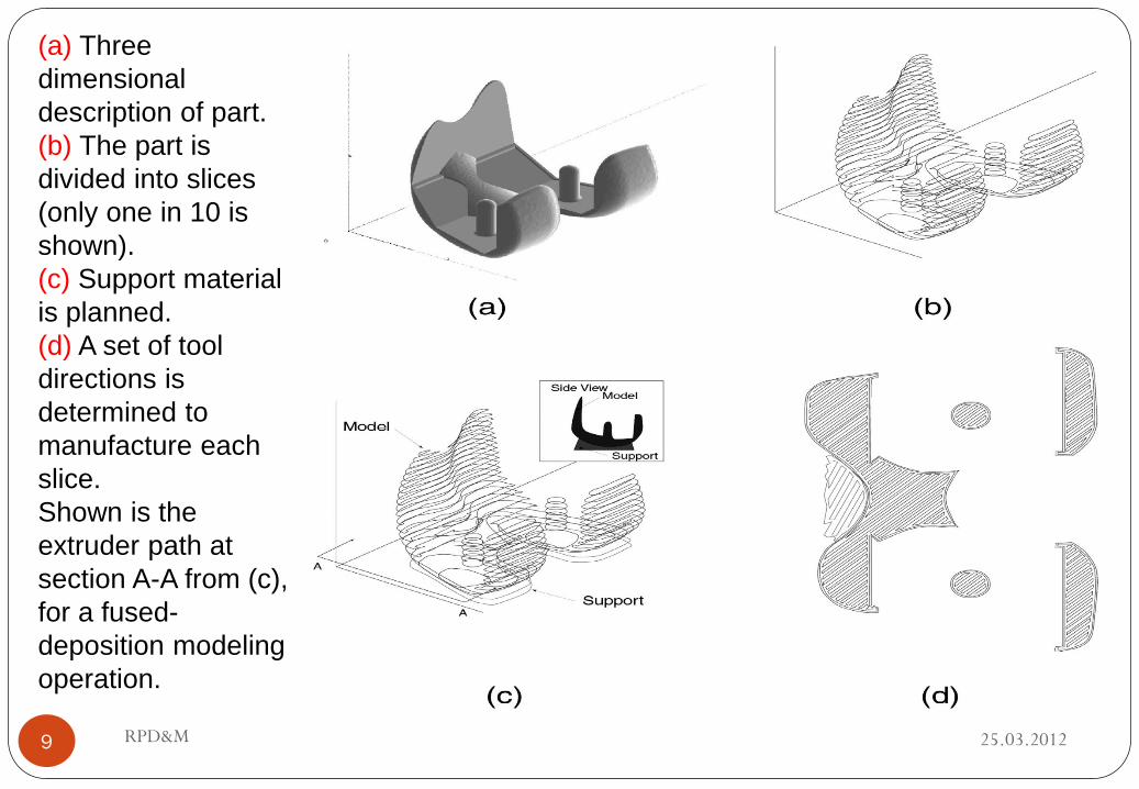
Prototyping technologies Base materials
Selective laser sintering (SLS) Thermoplastics, metals powders
Direct metal laser sintering (DMLS) Almost any alloy metal
Fused deposition modeling (FDM) Thermoplastics, eutectic metals
Stereolithography (SLA) photopolymer
Laminated object manufacturing (LOM) Paper
Electron beam melting (EBM) Titanium alloys
3D printing (3DP) Various materials
Additive Processes: RP Technologies
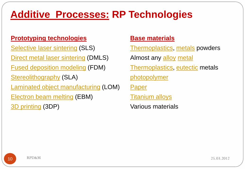
(1) Fused-deposition modelling (FDM)
In FDM process, a gantry robot-controlled
extruder head moves in two principal directions
over a table, which can be raised and lowered
as needed.
A thermoplastic filament is extruded through the
small orifice of a heated die.
The initial layer is placed on a foam foundation
by extruding the filament at a constant rate while
the extruder head follows a predetermined path.
When the first layer is completed, the table is
lowered so that subsequent layers can be
superimposed.
25.03.2012 RPD&M 11
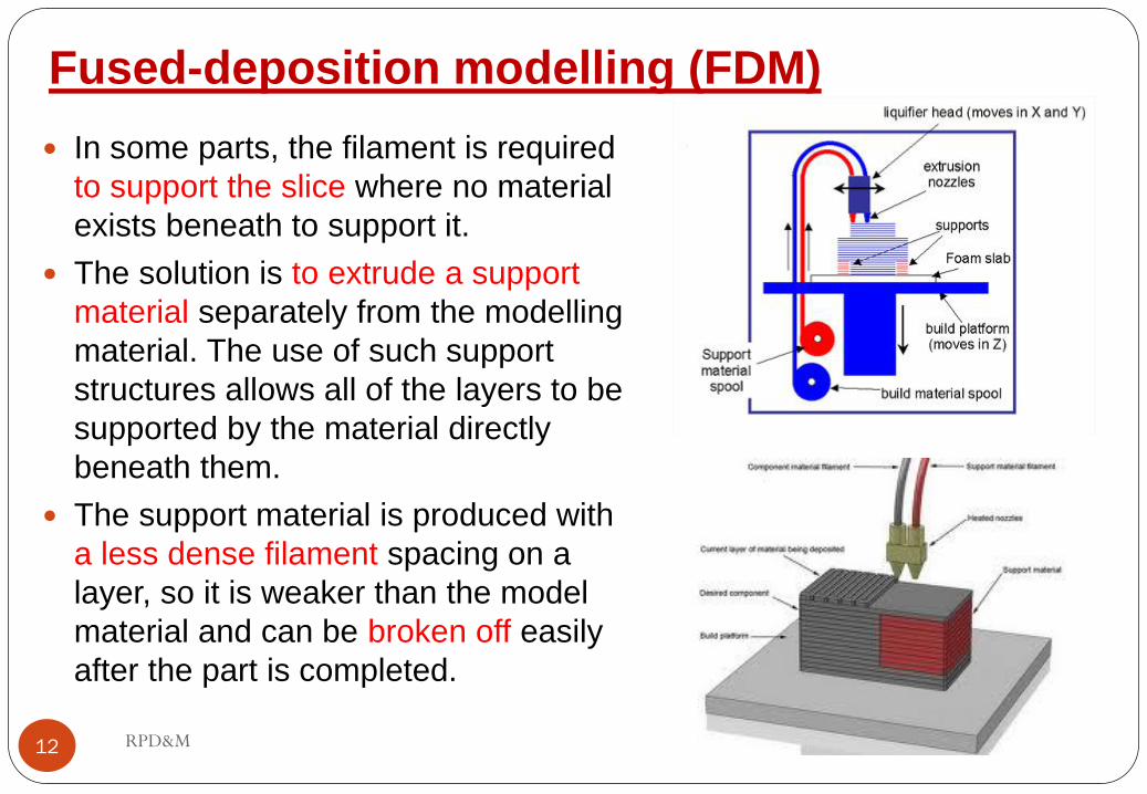
Fused-deposition modelling (FDM)
In some parts, the filament is required
to support the slice where no material
exists beneath to support it.
The solution is to extrude a support
material separately from the modelling
material. The use of such support
structures allows all of the layers to be
supported by the material directly
beneath them.
The support material is produced with
a less dense filament spacing on a
layer, so it is weaker than the model
material and can be broken off easily
after the part is completed.
25.03.2012 RPD&M 12

Fused-deposition modelling (FDM)
The layers in an FDM model are determined by
the extrusion-die diameter, which typically
ranges from 0.050 to 0.12mm. This thickness
represents the best achievable in the vertical
direction.
In the x-y plane, dimensional accuracy can be
as fine as 0.025mm as long as a filament can
be extruded into the feature.
A variety of polymers are available for different
applications.
Flat wire metal deposition uses a metal wire
instead of a polymer filament, but also needs a
laser to heat and bond the deposited wire to
build parts.
25.03.2012 RPD&M 13

25.03.2012 RPD&M 14

FDM Materials
ABS (Acrylonitrile Butadiene Styrene)
A strong, durable industrial-grade ABS plastic in a wide variety of colors. Its
strength is 60 to 80% that of injection molded ABS plastic
ABSi (Methyl methacrylate Acrylonitrile Butadiene Styrene)
Its strength is superior to ABS and the translucent nature of ABSi is beneficial for
monitoring material flow and light transmission, most commonly used for medical
and automotive applications. When combined with FDM systems, ABSi gives you
Real Parts that are visually unique, dimensionally accurate, durable and hold
shape over time.
25.03.2012 RPD&M 15
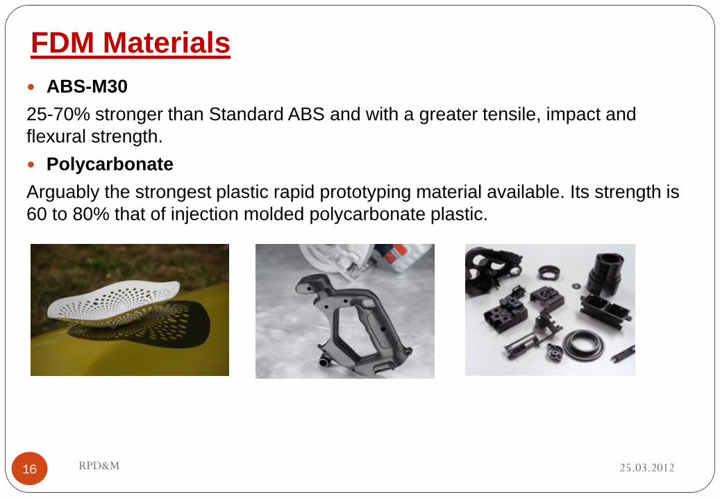
FDM Materials
ABS-M30
25-70% stronger than Standard ABS and with a greater tensile, impact and
flexural strength.
Polycarbonate
Arguably the strongest plastic rapid prototyping material available. Its strength is
60 to 80% that of injection molded polycarbonate plastic.
25.03.2012 RPD&M 16

FDM Materials
Polycarbonate/ABS
Blend of Polycarbonate (PC) and ABS plastic. This blend combines the
strength of PC with the flexibility of ABS. PC/ABS blends are used in
production of parts for the automotive, electronic, telecommunications,
and toy industries, among others. This blend has excellent thermal and
mechanical properties. It is significantly stronger than ABS, and feature
detail is similar to that of ABS modeling material
25.03.2012 RPD&M 17

FDM Materials
25.03.2012 RPD&M 18
ABS-ESD7
ABS-ESD7 is a durable and electrostatic dissipative material suited for End-
use components, Electronic products, Industrial equipment and Jigs and
fixtures for assembly of electronic components.
PC-ISO
PC-ISO blends are widely used throughout packaging and medical device
manufactures. The PC-ISO material used to build the FDM parts is USP
Class VI approved and also ISO 10993-1 rated.
ULTEM 9085
ULTEM 9085 is a pioneering thermoplastic that is strong, lightweight and
flame retardant (UL 94-V0 rated). The ULTEM 9085 material opens up new
opportunities for the direct additive construction of production grade
components.

FDM Materials
ABS application
Automotive body parts,
Dash boards, components and housings,
Electronic enclosures for business machines and consumer products;
sporting goods;
Handles and enclosures for power tools;
Prototypes and end-use parts in other industries such as aerospace,
medical, toys and industrial goods.
25.03.2012 RPD&M 19
FDM Materials
Application Areas of Polycarbonate
Pharmaceutical material handling, processing, and packaging systems;
Surgical instruments;
Food handling and processing systems;
Automotive lighting;
Rapid manufacturing of end-use products
25.03.2012 RPD&M 20

Advantages and Disadvantages
25.03.2012 RPD&M 21
The main advantage to using FDM is the very durable
parts that can be made using waxes and various
engineering plastics.
The drawback to using the FDM method is that the parts
generally take much longer to build and the layering is
clearly visible because of the extrusion type process.

(2) Stereolithography
A common RP process developed prior to FDM is stereolithography (SLA).
This process is based on the principle of curing (hardening) a liquid photopolymer into a specific shape.
A vat containing a mechanism whereby a platform can be lowered and raised is filled with a photocurable liquid-acrylate polymer.
The liquid is a mixture of acrylic monomers, oligomers (polymer intermediates), and a photoinitiator ( a compound that undergoes a reaction upon absorbing light).
25.03.2012 RPD&M 22

(2) Stereolithography
At its highest position (depth a), a shallow layer of liquid exists above the platform.
A laser generating an ultraviolet (UV) beam is focused upon a selected surface area of the photopolymer and then moved around in the x-y plane.
The beam cures that portion of the photopolymer and thereby produces a solid body.
The platform is then lowered sufficiently to cover the cured polymer with another layer of liquid polymer, and the sequence is repeated.
25.03.2012 RPD&M 23
The process is repeated until level b is reached. Thus far, we have generated a cylindirical part with a constant wall thickness. Note that the platform is now lowered by a vertical distance ab.

(2) Stereolithography
At level b, the x-y movements of the beam define a wider geometry, so we now have a flange-shaped portion that is being produced over the previously formed part.
After the proper thickness of the liquid has been cured, the process is repeated, producing another cylindirical section between levels b and c.
Note that the surrounding liquid polymer is still fluid (because it has not been exposed to the ultraviolet beam) and that the part has been produced from the bottom up in individual ‘slices’. The unused portion of the liquid polymer can be used again to make another part or another prototype.
25.03.2012 RPD&M 24

(2) Stereolithography
Stereolithography comes from the facts that the movements are three-dimensional and the process is similar to ‘lithography’ (is a method for printing using a stone (lithographic limestone) or a metal plate with a completely smooth surface) , in which the image to be printed on a flat surface is ink receptive and the blank areas are ink repellent.
Note also that, like FDM, SLA can utilize a weaker support material. In SLA, this support takes the form of perforated structures. After its completion, the part is removed from the platform, blotted, and cleaned ultrasonically and with an alcohol bath.
Then the support structure is removed, and the part is subjected to a final curing cycle in an oven.
The smallest tolerance that can be achieved in SLA depends on the sharpness of the focus of the laser; typically, it is around 0.0125mm.
Oblique surfaces can also be of very high quality.
25.03.2012 RPD&M 25

(2) Stereolithography
Total cycle times in SLA range from a few hours to a day – without postprocessing such as sanding and painting.
Depending on their capacity, the cost of the machines is in the range from $100,000 to $400,000.
The cost of liquid polymer is on the order from $80 per litre.
The maximum part size that can be produced is 0.5x0.5x0.6m.
SLA has been used with highly focused lasers to produce parts with micrometer-sized features (micro-STL).
25.03.2012 RPD&M 26

(2) Stereolithography Materials
Somos 7120 - A high speed general use resin that is heat and humidity resistant. Its a liquid photopolymer.
Somos 9120 - A robust accurate resin for functional parts.The material offers superior chemical resistance.It is a thermosetting polymer.
Somos 9920 - A durable resin whose properties mimic polypropylene(Thermoplastic Polymer). Offers superior chemical resistance and fatigue properties
Accura 50 White - A durable, accurate material for producing functional prototypes with the look and feel of molded ABS.
RenShape 5260 - A durable white resin that closely simulates ABS plastic.
25.03.2012 RPD&M 27

(2) Stereolithography Materials
Somos 10120 WaterClear - A general purpose resin with mid range mechanical properties. Transparent parts are possible if finished properly.
Somos 11120 WaterShed - Produces strong, tough, water-resistant parts. Many of its mechanical properties mimic that of ABS plastic.
Somos 14120 White - A low viscosity liquid photopolymer that produces strong, tough, water-resistant parts.
Somos ProtoTool - ProtoTool is a high density material that transcends currently available stereolithography resins by offering superior modulus and temperature resistance.
25.03.2012 RPD&M 28

(2) SLA support structures
25.03.2012 RPD&M 29
• Support usually need for liquid-based and solid-based RP systems in
order to anchor the part to the platform hence the part can be
seperated from the platform thus preventing floating layers and make
removal of the part become simple.
• Support can be classified according to the support structure and the
type of the surfaces being supported. Support types include solid, box,
web and finepoint supports.
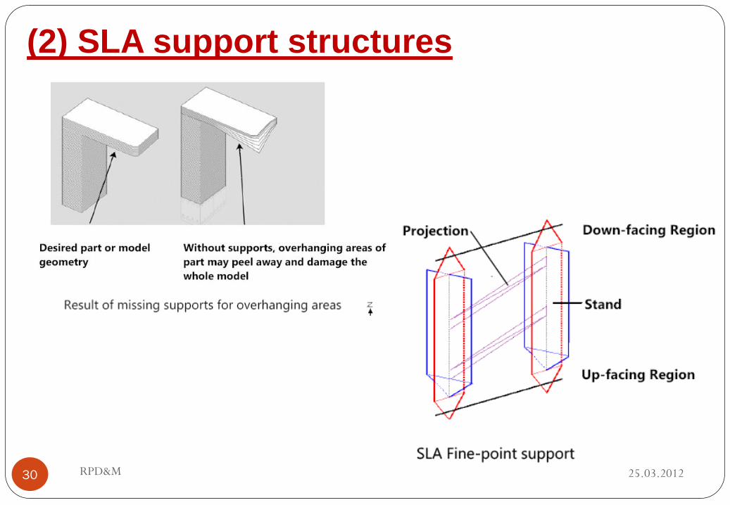
(2) SLA support structures
25.03.2012 RPD&M 30

(2) Stereolithography Interface
Stereolithograpy was first commercial Solid Freeform Manufacturing process, released in 80’s by 3-D Systems
3-D Systems developed interface between CAD systems and their machine
STL files (*.stl) allow CAD systems to interface with 3-D system machines
Virtually all subsequent SFM (solid free-form manufacturing or RP) processes can use this same format (SFM industry standard)
Many CAD programs now can export the *.stl file for easy conversion from CAD to part
25.03.2012 RPD&M 31

(2) Stl files (*.stl)
• STL files were based on a program called Silverscreen CAD
• Silverscreen CAD represent boundary with all surfaces being approximated by
polygons or groups of polygons.
• *.stl files use triangles or groups of triangles to approximate surfaces
• Accuracy depends on the triangle sizes
• Triangles assigned normal vectors for outward surface normal
• Parts are defined by representing all their bounding surfaces as faceted
surfaces, using the triangular patches
25.03.2012 RPD&M 32

(2) Stl representaion
25.03.2012 RPD&M 33
Representing
a sphere

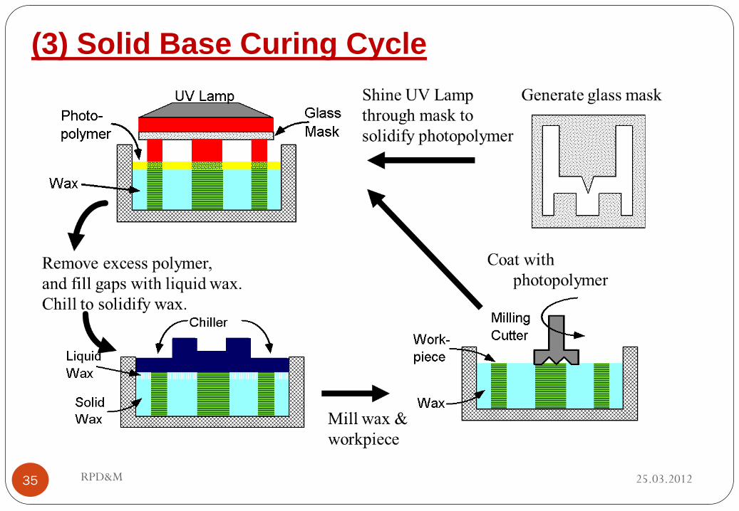
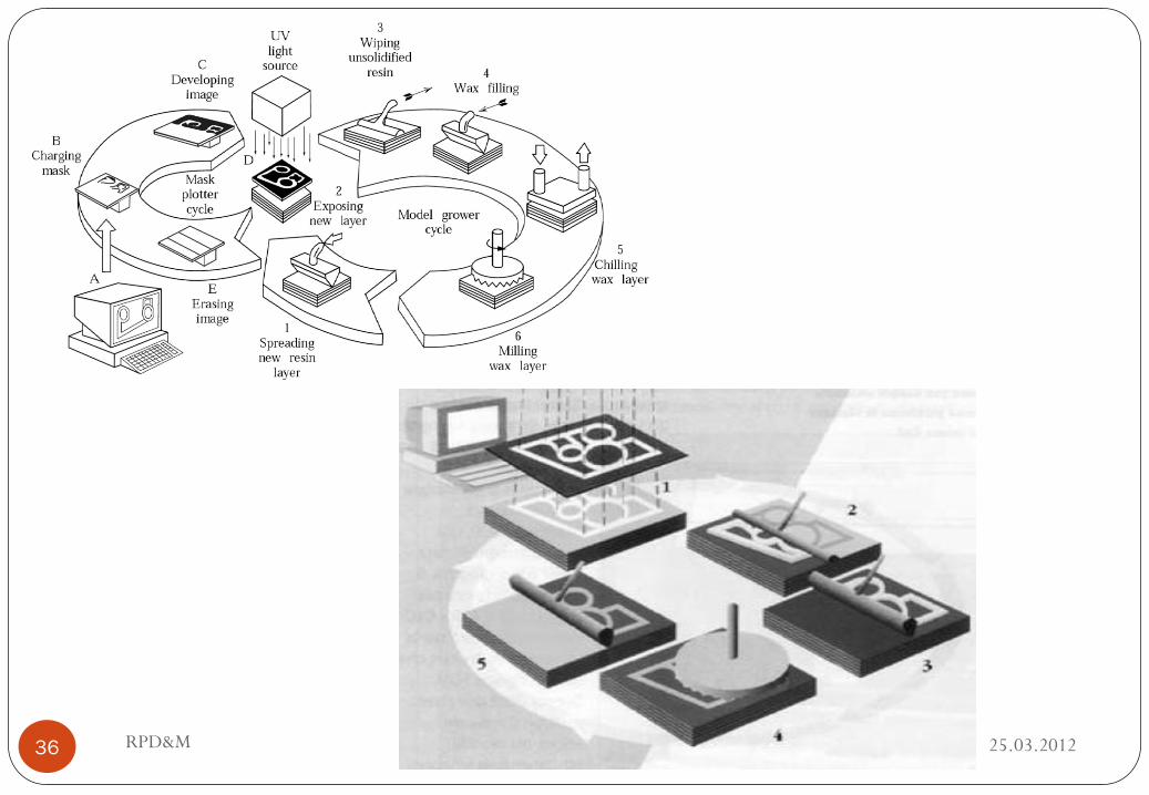
(3) Solid Base Curing
Cross section shape is “printed” onto a glass mask and this glass mask
is positioned above photopolymer tank.
UV lamp shines through mask onto photopolymer- light only can pass
through clear part, polymer solidifies there, polymer in masked areas
remains liquid.
All excess polymer is removed- part is again hit with UV light.
Melted wax is spread over workpiece, filling all spaces.
Workpiece is precisely milled flat.
Glass is erased and re-masked, workpiece is placed slightly below
surface in photopolymer, process repeats.
After fabricating part, wax is melted and removed.
Accurate, no support or post cure needed, but expensive & toxic.
25.03.2012 RPD&M 34
(3) Solid Base Curing Cycle
25.03.2012 RPD&M 35
25.03.2012 RPD&M 36
(4)Ballistic particle manufacturing (BPM)
25.03.2012 RPD&M 37
BMP uses CAD-generated three-dimensional solid model data to
direct streams of material (waxes, plastics, photocurable polymers,
ceramics, or metals) at a target, building three-dimensional objects
in much the same manner an ink jet-printer produces two-
dimensional images.
An object is built by a three-axis ro-botic system controlling a
piezoelectric ink-jet mechanism ”shooting” particles of the material,
producing multiple cross-sections, onto a target.
There are different ink jet techniques (deposition systems), but all
rely on squirting a build material in a liquid or melted state which
cools or otherwise hardens to form a solid on impact.

(4)Ballistic particle manufacturing (BPM)
Employs a technology called Digital
Microsynthesis
Molten plastic is fed to a piezoelectric jetting
mechanism, similar to those on inkjet
printers.
A multi-axis controlled NC system shoots tiny
droplets of material onto the target, using the
jetting mechanism.
Small droplets freeze upon contact with the
surface, forming the surface particle by
particle.
Process allows use of virtually any
thermoplastic (no health hazard) & offers the
possibility of using material other than
plastic.
25.03.2012 RPD&M 38

(4) BPM advantages & disadvantages
Advantages
Requires minimal post-processing.
Low toxicity.
Minimal power consumption.
Low cost and materials.
Ability to perform in microgravity and vacuum environments.
BPM has no size constraints.
The process allows use of virtually any thermoplastic. Because of this,
there are no heath hazards involved.
Disadvantages
Parts produced lack strength and durability.
25.03.2012 RPD&M 39

(4) Future of BPM
Developed system similar to BPM’s
System focuses on metal materials rather than plastic
There have been successful fabrications out of tin and aluminum
Major advantage of this product is the ability to produce large metal
parts
25.03.2012 RPD&M 40

(5) Selective Laser Sintering (SLS)
25.03.2012 RPD&M 41
SLS is a process based on the sintering of nonmetallic or (less
commonly) metallic powders selectively into an individual object.
The bottom of the processing
chamber is equipped with two
cylinders:
1. A powder-feeder cylinder,
which is raised incrementally
to supply powder to the part-
build cylinder through a roller
mechanism.
2. A part-build cylinder, which
is lowered incrementally as
the part is being formed.

(5) Selective Laser Sintering (SLS)
25.03.2012 RPD&M 42
First, a thin layer of powder is deposited in the part-build cylinder.
Then, a laser beam guided by a process-control computer using instructions generated by the 3D CAD program of the desired part is focused on that layer, tracing and sintering a particular cross-section into a solid mass.
The powder in other areas remains loose, yet it supports the sintering portion.
Another layer of powder is then deposited; this cycle is repeated again and again until the entire 3D part has been produced.
The loose particles are shaken off, and the part is recovered.
The part does not require further curing-unless it is a ceramic, which has to be fired to develop strength.

(5) Selective Laser Sintering (SLS)
25.03.2012 RPD&M 43
A variety of materials can be used in this
process, including polymers (such as ABS;
PVC, nylon, polyester, polystyrene, and
epoxy), wax, metals, and ceramics with
appropriate binders.
It is most common to use polymers because
of the smaller and less expensive, and less
complicated lasers are required for sintering.
With ceramics and metals, it is common to
sinter only a polymer binder that has been
blended with the ceramic or metal powders.
The resultant part can be carefully sintered is
a furnace and infiltrated with another metal if
desired.

(6) Electron-beam Melting (EBM)
25.03.2012 RPD&M 44
A process similar to SLS and electron beam
welding, EBM uses the energy source
associated with an electron beam to melt
titanium or cobalt-chrome powder to make
metal prototypes.
The workpiece is produced in a vacuum; the
part build size is limited to around
200x200x180 mm.
EBM is up to 95% efficient from energy
standpoint (compared with 10-20% efficiency
for SLS), so that the titanium powder is
actually melted and fully dense parts can be
produced.

(6) Electron-beam Melting (EBM)
25.03.2012 RPD&M 45
A volume build rateof up to 60cm³/hr can be obtained, with individual layer
thicknesses of 0.050-0.200 mm.
Hot isostatic pressing also can be performed on parts to improve their fatigue
strength.
Although the applied mainly to titanium and cobalt-chrome to date, the process
is being developed for stainless steels, aluminum, and copper alloys.

(7) 3D Printing
25.03.2012 RPD&M 46
In 3D Printing (3DP) process, a print head deposits an inorganic binder
material onto a layer of polymer, ceramic, or metallic powder.
A piston supporting the powder bed is lowered incrementally, and with each
step, a layer is deposited and then fused by the binder.

(7) 3D Printing
25.03.2012 RPD&M 47
3DP allows considerable flexibility in the materials and
binders used.
Commonly used powder materials are blends of polymers
and fibers, foundary sands, and metals.
Furthermore, since multiple binders printheads can be
incorporated into a machine, it is possible to produce full-
color prototypes by having different-color binders.
The effect is a 3D anolog to printing photographs using
three ink colors on an ink-jet printer.
A common part produced by 3DP from ceramic powder is
a ceramic-casting shell, in which an aluminum-oxide or
aluminum silica powder is fused with a silica binder.
The molds have to be postprocessed in two steps:
(1) curing at around 150ºC and
(2) firing at 1000º to 1500ºC.

(7) 3D Printing
25.03.2012 RPD&M 48
The parts produced through the 3DP process are somewhat porous and
therefore may lack strength.
3DP of metal powders can also be combined with sintering and metal filtration
to produce fully dense parts, using the sequence.
The part is produced as before directing the binder onto powders. However, the
build sequence is then followed by sintering to burn off the binder and partially
fuse the metal powders, just as in powder injection molding.
3DP using;
(a) part-build,
(b) sinter,
(c) infiltration steps to
produce metal parts.

(7) 3D Printing
26.03.2012 RPD&M 49
Common metals used in 3DP are stainless steels, aluminum, and titanium.
Infiltrating materials typically are copper and bronze, which provide good
heat-transfer capabilities as well as wear resistance.

(8) Laminated-object Manufacturing (LOM)
25.03.2012 RPD&M 50
Lamination implies a laying down of layers that are bonded
adhesively to one another.
Several variations of LOM are available.
The simples and least expensive versions of LOM involve
using control software and vinyl cutters to produce the
prototype.
Vinyl cutters are simple CNC machines that cut shapes from
vinyl or paper sheets.
Each sheet then has a number of layers and registration
holes, which allow proper alignment and placement onto a
build fixture.
LOM systems are highly ecenomical and are popular in
schools and universities because of the hands-on
demenstration of additive manufactring and production of
parts by layers.

25.03.2012 RPD&M 51
(8) Laminated-object Manufacturing (LOM)
(a) Schematic illustration of the laminated-object-manufacturing
process.
(b) Crankshaft-part example made by LOM.

(8) Laminated-object Manufacturing (LOM)
25.03.2012 RPD&M 52
LOM systems can be elaborate; the more advanced
systems use layers of paper or plastic with a heat-
activated glue on one side to produce parts.
The desired shapes are burned into the sheet with a
laser, and the parts are built layer by layer.
On some systems, the excess material must be
removed manually once the part is completed.
Removal is simplified by programming the laser to
burn perforations in crisscrossed patterns.
The resulting grid lines make the part appear as if it
had been constructed from gridded paper (with
squares printed on it, similar to graph paper).