Rapid Manufacturing in Biomedical Materials: Using...
11
Rapid Manufacturing in Biomedical Materials: Using Subtractive Rapid Prototyping for Bone Replacement Matthew C. Frank, PhD, Christopher V. Hunt Department of Industrial and Manufacturing Systems Engineering Iowa State University, Ames, IA, USA Donald D. Anderson, PhD, Todd O. McKinley, M.D., Thomas D. Brown, PhD Department of Orthopaedics and Rehabilitation The University of Iowa, Iowa City, IA, USA Abstract Reviewed, accepted September 10, 2008 This paper presents methods for the rapid manufacturing of replacement bone fragments using a Subtractive Rapid Prototyping process called CNC-RP. The geometry of segmental defects in bone, resulting from traumatic injury or cancerous tumor resection, can be reverse-engineered working from medical images (such as CT scans), and then accurate defect fillers can be automatically generated in advanced synthetic biomaterials and other bioactive/biocompatible materials. The research provides evidence that suitable bone geometries can be created using subtractive RP from a variety of materials including Trabecular Metal ® (porous tantalum), polymers, ceramics, and actual bone allografts. The research has implications in the orthopaedic treatment of segmental bone defects, as custom prototyped bone fillers should aid in bone growth and improve recovery. Introduction Medical implants are produced from many different biocompatible materials, based on their size, shape, placement in the body, and overall functionality. More specifically, implants used in bone repair and joint replacement have been made from solid and porous stainless steel, ceramics, natural coral, allograft and autograft bone, and different alloys of titanium and cobalt, among others. Each of these materials has specific limitations with regard to manufacturability and functionality, both critical considerations in bone implant design and manufacture. There is a challenge in creating accurate shaped implants using biosensitive materials; in particular for those using specialized materials, or naturally occurring materials such as bone or coral. Subtractive Rapid Prototyping (SRP) is particularly well-suited for such a highly customized and material-specific challenge. Rapid prototyping using CNC machining, or CNC-RP (Frank et al., 2002; Frank, 2007) is a fully functional SRP system that can automatically generate fixture, tooling and setup plans, including all NC code for creating a part, directly from a CAD file. 686
Transcript of Rapid Manufacturing in Biomedical Materials: Using...
Rapid Manufacturing in Biomedical Materials: Using Subtractive Rapid Prototyping for Bone Replacement
Matthew C. Frank, PhD, Christopher V. Hunt
Department of Industrial and Manufacturing Systems Engineering Iowa State University, Ames, IA, USA
Donald D. Anderson, PhD, Todd O. McKinley, M.D., Thomas D. Brown, PhD
Department of Orthopaedics and Rehabilitation The University of Iowa, Iowa City, IA, USA
Abstract Reviewed, accepted September 10, 2008 This paper presents methods for the rapid manufacturing of replacement bone fragments using a Subtractive Rapid Prototyping process called CNC-RP. The geometry of segmental defects in bone, resulting from traumatic injury or cancerous tumor resection, can be reverse-engineered working from medical images (such as CT scans), and then accurate defect fillers can be automatically generated in advanced synthetic biomaterials and other bioactive/biocompatible materials. The research provides evidence that suitable bone geometries can be created using subtractive RP from a variety of materials including Trabecular Metal® (porous tantalum), polymers, ceramics, and actual bone allografts. The research has implications in the orthopaedic treatment of segmental bone defects, as custom prototyped bone fillers should aid in bone growth and improve recovery. Introduction Medical implants are produced from many different biocompatible materials, based on their size, shape, placement in the body, and overall functionality. More specifically, implants used in bone repair and joint replacement have been made from solid and porous stainless steel, ceramics, natural coral, allograft and autograft bone, and different alloys of titanium and cobalt, among others. Each of these materials has specific limitations with regard to manufacturability and functionality, both critical considerations in bone implant design and manufacture. There is a challenge in creating accurate shaped implants using biosensitive materials; in particular for those using specialized materials, or naturally occurring materials such as bone or coral. Subtractive Rapid Prototyping (SRP) is particularly well-suited for such a highly customized and material-specific challenge. Rapid prototyping using CNC machining, or CNC-RP (Frank et al., 2002; Frank, 2007) is a fully functional SRP system that can automatically generate fixture, tooling and setup plans, including all NC code for creating a part, directly from a CAD file.
686
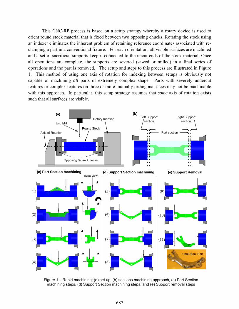
This CNC-RP process is based on a setup strategy whereby a rotary device is used to orient round stock material that is fixed between two opposing chucks. Rotating the stock using an indexer eliminates the inherent problem of retaining reference coordinates associated with re-clamping a part in a conventional fixture. For each orientation, all visible surfaces are machined and a set of sacrificial supports keep it connected to the uncut ends of the stock material. Once all operations are complete, the supports are severed (sawed or milled) in a final series of operations and the part is removed. The setup and steps to this process are illustrated in Figure 1. This method of using one axis of rotation for indexing between setups is obviously not capable of machining all parts of extremely complex shape. Parts with severely undercut features or complex features on three or more mutually orthogonal faces may not be machinable with this approach. In particular, this setup strategy assumes that some axis of rotation exists such that all surfaces are visible.
(Side View) (Side View)
(1)
(2)
(3)
(4)
(5)
(6)
(7)
(8)
(9)
(10)
(11)
(c) Part Section machining (d) Support Section machining (e) Support Removal
Figure 1 – Rapid machining; (a) set up, (b) sections machining approach, (c) Part Section
machining steps, (d) Support Section machining steps, and (e) Support removal steps
Axis of Rotation
Opposing 3-Jaw Chucks
Round Stock
End Mill
(a) Rotary Indexer
(b)
Part section
Left Support section
Right Support section
Final Steel Part
687
The rapid machining process incrementally creates the part by machining layer by layer
for each orientation, thus it is not very fast and would not be a good choice for production manufacturing. However, this process is extremely rapid in that it can automatically begin processing a part directly from a CAD file. The research so far has developed algorithms that automatically analyze the part geometry and determine 1) if the part is machinable, 2) if so, how many orientations are required, and 3) all process parameters including the stock size, tool size, feeds, speeds, sacrificial support geometry and the sequence of operations. This new rapid machining process is novel in that it approaches the planning steps in a “feature-free” manner using robust automated methods. That is, geometric algorithms calculate the steps necessary to machine all the surfaces of the object. The process begins with a 3D model and generates the required processing code for a computer numerically controlled (CNC) milling machine (Frank et al, 2006, Li and Frank, 2006,2007).
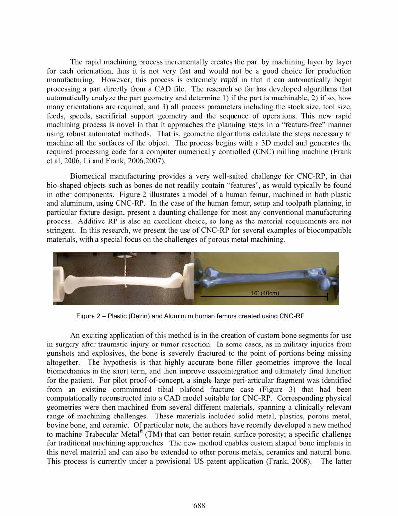
Biomedical manufacturing provides a very well-suited challenge for CNC-RP, in that bio-shaped objects such as bones do not readily contain “features”, as would typically be found in other components. Figure 2 illustrates a model of a human femur, machined in both plastic and aluminum, using CNC-RP. In the case of the human femur, setup and toolpath planning, in particular fixture design, present a daunting challenge for most any conventional manufacturing process. Additive RP is also an excellent choice, so long as the material requirements are not stringent. In this research, we present the use of CNC-RP for several examples of biocompatible materials, with a special focus on the challenges of porous metal machining.
An exciting application of this method is in the creation of custom bone segments for use in surgery after traumatic injury or tumor resection. In some cases, as in military injuries from gunshots and explosives, the bone is severely fractured to the point of portions being missing altogether. The hypothesis is that highly accurate bone filler geometries improve the local biomechanics in the short term, and then improve osseointegration and ultimately final function for the patient. For pilot proof-of-concept, a single large peri-articular fragment was identified from an existing comminuted tibial plafond fracture case (Figure 3) that had been computationally reconstructed into a CAD model suitable for CNC-RP. Corresponding physical geometries were then machined from several different materials, spanning a clinically relevant range of machining challenges. These materials included solid metal, plastics, porous metal, bovine bone, and ceramic. Of particular note, the authors have recently developed a new method to machine Trabecular Metal® (TM) that can better retain surface porosity; a specific challenge for traditional machining approaches. The new method enables custom shaped bone implants in this novel material and can also be extended to other porous metals, ceramics and natural bone. This process is currently under a provisional US patent application (Frank, 2008). The latter
Figure 2 – Plastic (Delrin) and Aluminum human femurs created using CNC-RP
16” (40cm)
688
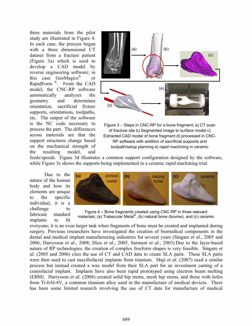
three materials from the pilot study are illustrated in Figure 4. In each case, the process began with a three dimensional CT dataset from a fracture patient (Figure 3a) which is used to develop a CAD model by reverse engineering software; in this case GeoMagics® or RapidForm ®. From the CAD model, the CNC-RP software automatically analyzes the geometry and determines orientation, sacrificial fixture supports, orientations, toolpaths, etc. The output of the software is the NC code necessary to process the part. The differences across materials are that the support structures change based on the mechanical strength of the resulting model, and feeds/speeds. Figure 3d illustrates a common support configuration designed by the software, while Figure 3e shows the supports being implemented in a ceramic rapid machining trial.
Due to the
nature of the human body and how its elements are unique to the specific individual, it is a challenge to fabricate standard implants to fit everyone; it is an even larger task when fragments of bone must be created and implanted during surgery. Previous researchers have investigated the creation of biomedical components in the dental and medical implant manufacturing industries for several years (Singare et al., 2005 and 2006; Harrysson et al., 2008; Hieu et al., 2005, Sarment et al., 2003).Due to the layer-based nature of RP technologies, the creation of complex freeform shapes is very feasible. Singare et al. (2005 and 2006) cites the use of CT and CAD data to create SLA parts. These SLA parts were then used to cast maxillofacial implants from titanium. Maji et al. (2007) used a similar process but instead created a wax model from their SLA part for an investment casting of a craniofacial implant. Implants have also been rapid prototyped using electron beam melting (EBM). Harrysson et al. (2008) created solid hip stems, mesh hip stems, and those with holes from Ti-6Al-4V, a common titanium alloy used in the manufacture of medical devices. There has been some limited research involving the use of CT data for manufacture of medical
Figure 4 – Bone fragments created using CNC-RP in three relevant materials; (a) Trabecular Metal®, (b) natural bone (bovine), and (c) ceramic
porous metal
natural bone
ceramic
(a) (b) (c)
Figure 3 – Steps in CNC-RP for a bone fragment; a) CT scan of fracture site b) Segmented image to surface model c)
Extracted CAD model of bone fragment d) processed in CNC-RP software with addition of sacrificial supports and
toolpath/setup planning e) rapid machining in ceramic
(a) (b) (c)
(d)
(e)
689

implants via machining of metal. Werner et al., 2000, outlined a methodology for the design and manufacture of a custom femur endoprosthesis. In their methodology, the CAD data for the specific bone came from a CT scan. From these CT data, a 3D geometric model of the femur was created and used to generate tool paths, conventionally, for a CNC milling process. However, the accuracy of the finished product was limited due to their machining process. This part required an elaborate fixturing system and only utilized two cutting orientations. Truscott et al., 2007, developed a similar method that involved machining an elbow joint from titanium stock. The machined titanium implant took approximately 104 hours of machining, over eight days (Truscott et al., 2007).
The probability of a successful bone implantation, and resulting functionality, not only depends on the surgical operation but also upon the implant material used and how that material interacts with the host bone. The long term issue of fixing the implant to the host bone has not yet been perfected. At surgery, many different short term fixation methods can be utilized such as wiring, pinning, the use of bone screws, plates, bone cement, as well as combinations of these methods. However, short term fixation does not guarantee a stable long term construct, and in cases of high impact trauma, bone can be obliterated beyond the capability of these fixation methods. More recently, improved fixation has been achieved using a porous structure of biosensitive metal into and through which bone tissue can grow (Bobyn et al., 1999; Garret et al., 2006; Harrysson et al., 2008; Macheras et al., 2006; Zou et al., 2004). The most successful fixation results when this osseointegration can take place across the bone-implant interface. Implant stability is not only a function of the material strength but also depends on the fixation established with surrounding tissues (Garret et al., 2006). Some porous metals have been found to possess physical and mechanical properties similar to bone (Bobyn et al., 1999). One material in particular, is a porous tantalum manufactured by Zimmer, Inc., called Trabecular Metal®, or TM. TM has been used in a large number of orthopaedic implants since its inception in the early 1990’s by Ultramet, a research and development firm (Deglurkar et al., 2006). Due to its high porosity, Trabecular Metal® is uniquely conducive to bone formation, enabling both strong attachment and fast, extensive tissue infiltration (Bobyn et al., 1999). The similarity of Trabecular Metal® to cancellous bone is shown in Figure 5. TM has been primarily used for spinal and joint reconstructive implants. These implants are not typically made entirely from open cell TM; rather, only select areas and implant surfaces that interact with host bone. The shapes of these TM parts are quite simple and due to the nature of TM and its current manufacturing processes, the option for customizable, patient-specific, TM parts is not commercially feasible at this time. Oftentimes, orthopedic surgeons are forced to make implant modifications by hand during surgery, in order to better fit the implant to the patient. This paper describes the initial steps toward the custom manufacture of patient-specific bone implants from a variety of biocompatible materials, including TM.
Figure 5 – Porosity comparison of cancellous bone (top) and Trabecular Metal ® (bottom) (www.zimmer.com)
690
Machining Porous Metals
Due to the cellular structure of metal foams, the surface porosity is often compromised by traditional machining methods (Bram et al., 2003; Chen et al., 2005; Deglurkar et al., 2006; MPIF, 2004; Laptev et al., 2004). The thin interconnected cell walls offer little internal support against the machining forces created by such processes (Deglurkar et al., 2006). The resulting smearing takes place when the cellular walls collapse under these forces. The degree to which this smearing occurs varies among different materials depending upon the specific machining method and machining parameters. Hence, manufacturers use methods such as electrical discharge machining (EDM), a spark erosion process that does not mechanically impinge on the material surface. There are significant limitations of using EDM, mainly due to the geometry that can be created easily. In one method, an EDM electrode is a shaped tool that can only be used for a particular custom shape. Another method is to use wire EDM, but it has limited ability to create geometry, in particular concave surfaces, since the wire must be able to span the surface. Deglurkar et al., (2006) evaluated the resulting surface porosity when machining Trabecular Metal® with a conventional lathe versus an electric discharge wire cutting (wire EDM) machine. The outcome of their research proved that the wire EDM process caused less smearing upon the TM samples than that left by turning.
New Process for Machining Metal Foam
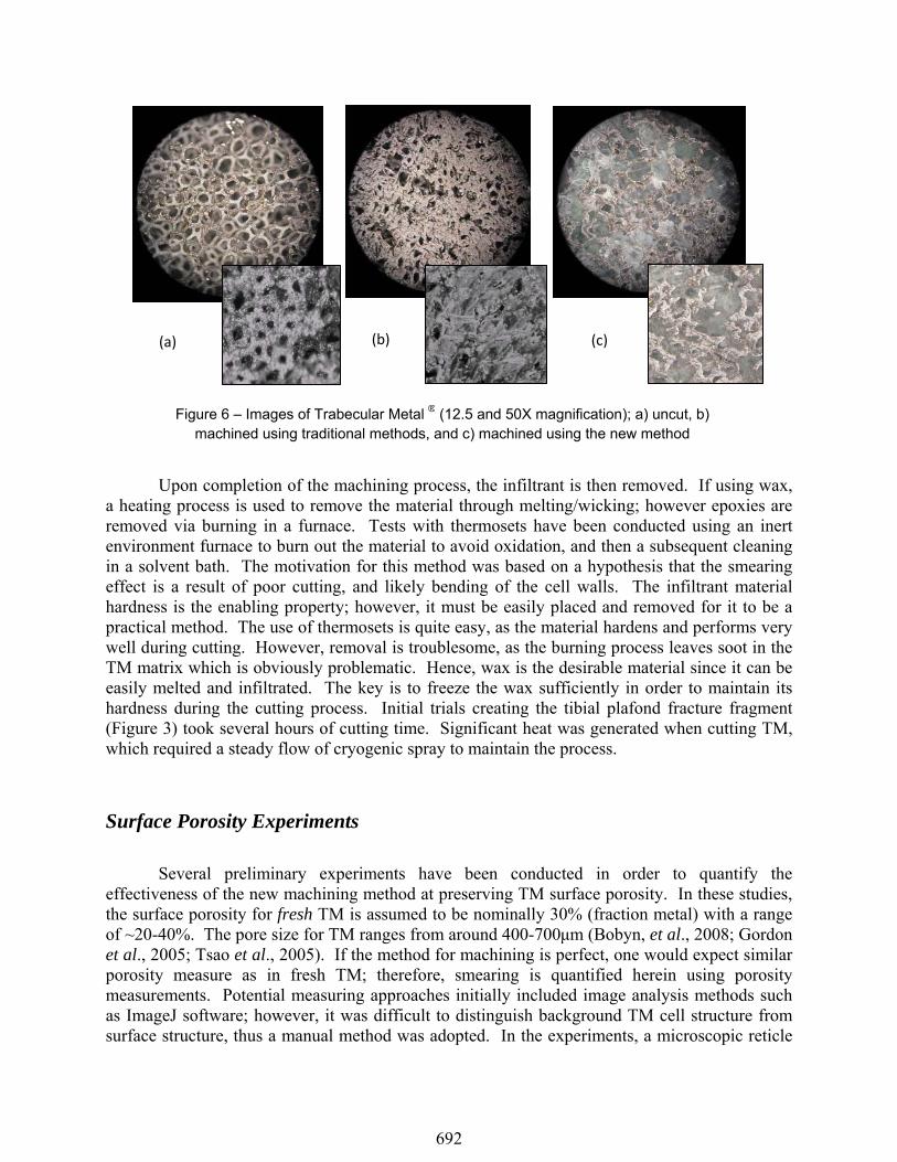
Maintaining the porosity of an open cell, porous metal is vital in preserving the metal’s functionality and performance. Porous metals, or metal foams, boast a large number of applications outside of the biomedical realm such as filtration, fluidization, silencing, as well as serving as lightweight structural members and catalytic supports (Brothers and Dunand, 2006; MPIF, 2004). As discussed previously, when a traditional machining approach is used, the surface of the material smears. Evidence of this is shown in the traditionally machined sample shown in Figure 6b versus the uncut TM shown in Figure 6a. In contrast, Figure 6c illustrates the same material cut using the new method described in this paper.
This is the first method capable of machining foams using conventional machining processes, instead of non-traditional methods such as electrical discharge machining. EDM is capable of cutting the material without smearing, but is not an easily customizable process. Moreover, recent research has shown that EDM has a detrimental effect on the material properties, in particular, a reduction in porosity (Deglurkar et al., 2006). Initial testing of our newly invented process indicates that the porosity of the TM may not be affected using the new approach.
The method is enabled through the use of an infiltrant material, which is subsequently removed after machining. The purpose of the infiltrant material is to act as a support structure for the cellular walls of the foam. As such, the infiltrant prohibits the foam walls from bending/smearing during the cutting process. Depending on the infiltrant used, a subsequent freezing process is used prior to and during machining to maintain its hardness. The method has been preliminarily tested using different waxes with varying hardness and thermoset epoxy; however, the process is not limited to only these materials. Tests so far have used an aerosol freezing spray and a liquid nitrogen spray when using waxes.
691
Upon completion of the machining process, the infiltrant is then removed. If using wax,
a heating process is used to remove the material through melting/wicking; however epoxies are removed via burning in a furnace. Tests with thermosets have been conducted using an inert environment furnace to burn out the material to avoid oxidation, and then a subsequent cleaning in a solvent bath. The motivation for this method was based on a hypothesis that the smearing effect is a result of poor cutting, and likely bending of the cell walls. The infiltrant material hardness is the enabling property; however, it must be easily placed and removed for it to be a practical method. The use of thermosets is quite easy, as the material hardens and performs very well during cutting. However, removal is troublesome, as the burning process leaves soot in the TM matrix which is obviously problematic. Hence, wax is the desirable material since it can be easily melted and infiltrated. The key is to freeze the wax sufficiently in order to maintain its hardness during the cutting process. Initial trials creating the tibial plafond fracture fragment (Figure 3) took several hours of cutting time. Significant heat was generated when cutting TM, which required a steady flow of cryogenic spray to maintain the process.
Surface Porosity Experiments
Several preliminary experiments have been conducted in order to quantify the effectiveness of the new machining method at preserving TM surface porosity. In these studies, the surface porosity for fresh TM is assumed to be nominally 30% (fraction metal) with a range of ~20-40%. The pore size for TM ranges from around 400-700μm (Bobyn, et al., 2008; Gordon et al., 2005; Tsao et al., 2005). If the method for machining is perfect, one would expect similar porosity measure as in fresh TM; therefore, smearing is quantified herein using porosity measurements. Potential measuring approaches initially included image analysis methods such as ImageJ software; however, it was difficult to distinguish background TM cell structure from surface structure, thus a manual method was adopted. In the experiments, a microscopic reticle
Figure 6 – Images of Trabecular Metal ® (12.5 and 50X magnification); a) uncut, b) machined using traditional methods, and c) machined using the new method
(a) (b) (c)
692
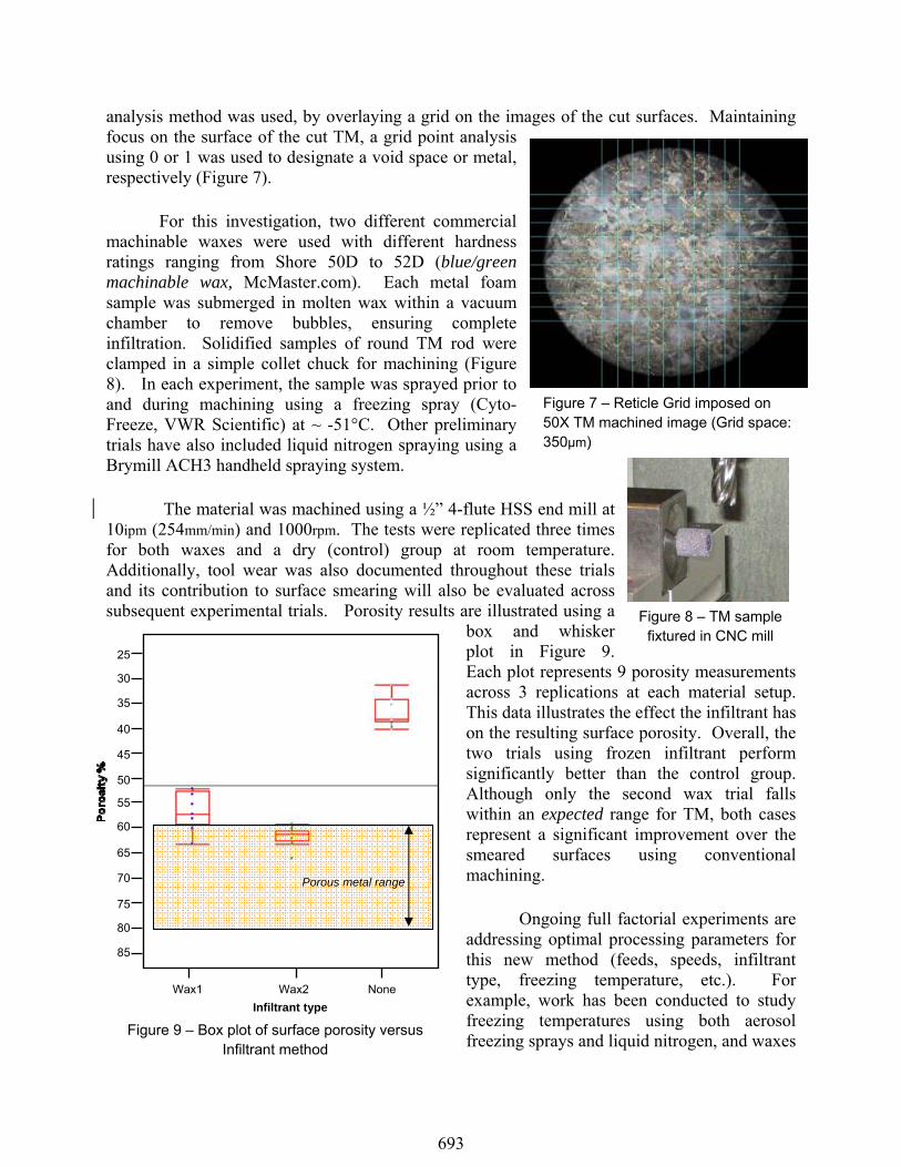
analysis method was used, by overlaying a grid on the images of the cut surfaces. Maintaining focus on the surface of the cut TM, a grid point analysis using 0 or 1 was used to designate a void space or metal, respectively (Figure 7).
For this investigation, two different commercial
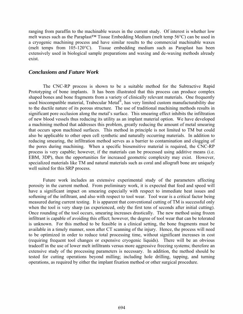
machinable waxes were used with different hardness ratings ranging from Shore 50D to 52D (blue/green machinable wax, McMaster.com). Each metal foam sample was submerged in molten wax within a vacuum chamber to remove bubbles, ensuring complete infiltration. Solidified samples of round TM rod were clamped in a simple collet chuck for machining (Figure 8). In each experiment, the sample was sprayed prior to and during machining using a freezing spray (Cyto-Freeze, VWR Scientific) at ~ -51°C. Other preliminary trials have also included liquid nitrogen spraying using a Brymill ACH3 handheld spraying system.
The material was machined using a ½” 4-flute HSS end mill at
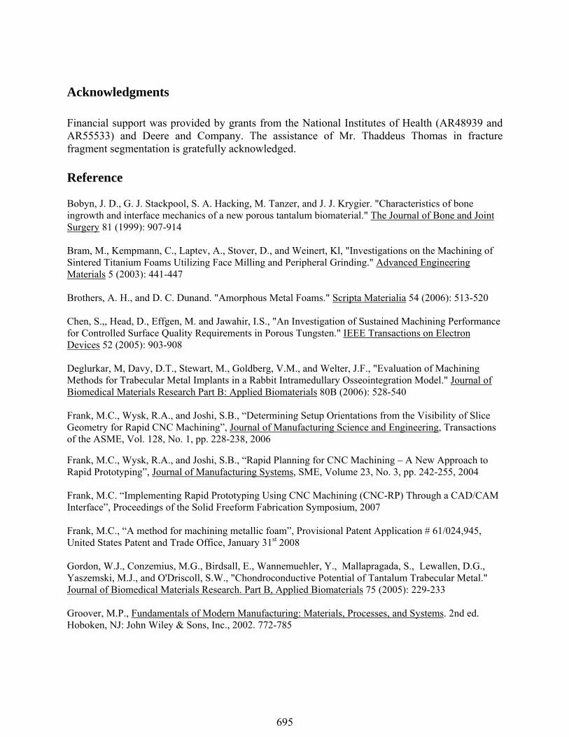
10ipm (254mm/min) and 1000rpm. The tests were replicated three times for both waxes and a dry (control) group at room temperature. Additionally, tool wear was also documented throughout these trials and its contribution to surface smearing will also be evaluated across subsequent experimental trials. Porosity results are illustrated using a
box and whisker plot in Figure 9. Each plot represents 9 porosity measurements across 3 replications at each material setup. This data illustrates the effect the infiltrant has on the resulting surface porosity. Overall, the two trials using frozen infiltrant perform significantly better than the control group. Although only the second wax trial falls within an expected range for TM, both cases represent a significant improvement over the smeared surfaces using conventional machining.
Ongoing full factorial experiments are
addressing optimal processing parameters for this new method (feeds, speeds, infiltrant type, freezing temperature, etc.). For example, work has been conducted to study freezing temperatures using both aerosol freezing sprays and liquid nitrogen, and waxes
Figure 8 – TM sample fixtured in CNC mill
Figure 7 – Reticle Grid imposed on 50X TM machined image (Grid space: 350μm)
Figure 9 – Box plot of surface porosity versus Infiltrant method
55
50
45
70
65
60
25
40
35
30
75
85
80
Porous metal range
Wax1 Wax2 None Infiltrant type
693
ranging from paraffin to the machinable waxes in the current study. Of interest is whether low melt waxes such as the Paraplast™ Tissue Embedding Medium (melt temp 56°C) can be used in a cryogenic machining process and have similar results to the commercial machinable waxes (melt temps from 105-120°C). Tissue embedding medium such as Paraplast has been extensively used in biological sample preparations and waxing and de-waxing methods already exist. Conclusions and Future Work The CNC-RP process is shown to be a suitable method for the Subtractive Rapid Prototyping of bone implants. It has been illustrated that this process can produce complex shaped bones and bone fragments from a variety of clinically relevant materials. One frequently used biocompatible material, Trabecular Metal®, has very limited custom manufacturability due to the ductile nature of its porous structure. The use of traditional machining methods results in significant pore occlusion along the metal’s surface. This smearing effect inhibits the infiltration of new blood vessels thus reducing its utility as an implant material option. We have developed a machining method that addresses this problem, greatly reducing the amount of metal smearing that occurs upon machined surfaces. This method in principle is not limited to TM but could also be applicable to other open cell synthetic and naturally occurring materials. In addition to reducing smearing, the infiltration method serves as a barrier to contamination and clogging of the pores during machining. When a specific biosensitive material is required, the CNC-RP process is very capable; however, if the materials can be processed using additive means (i.e. EBM, 3DP), then the opportunities for increased geometric complexity may exist. However, specialized materials like TM and natural materials such as coral and allograft bone are uniquely well suited for this SRP process. Future work includes an extensive experimental study of the parameters affecting porosity in the current method. From preliminary work, it is expected that feed and speed will have a significant impact on smearing especially with respect to immediate heat issues and softening of the infiltrant, and also with respect to tool wear. Tool wear is a critical factor being measured during current testing. It is apparent that conventional cutting of TM is successful only when the tool is very sharp (as experienced, only the first tens of seconds after initial cutting). Once rounding of the tool occurs, smearing increases drastically. The new method using frozen infiltrant is capable of avoiding this effect; however, the degree of tool wear that can be tolerated is unknown. For this method to be feasible in a clinical setting, the bone fragments must be available in a timely manner, soon after CT scanning of the injury. Hence, the process will need to be optimized in order to reduce total processing time, without significant increases in cost (requiring frequent tool changes or expensive cryogenic liquids). There will be an obvious tradeoff in the use of lower melt infiltrants versus more aggressive freezing systems; therefore an extensive study of the processing parameters is necessary. In addition, the method should be tested for cutting operations beyond milling; including hole drilling, tapping, and turning operations, as required by either the implant fixation method or other surgical procedure.
694
Acknowledgments Financial support was provided by grants from the National Institutes of Health (AR48939 and AR55533) and Deere and Company. The assistance of Mr. Thaddeus Thomas in fracture fragment segmentation is gratefully acknowledged. Reference Bobyn, J. D., G. J. Stackpool, S. A. Hacking, M. Tanzer, and J. J. Krygier. "Characteristics of bone ingrowth and interface mechanics of a new porous tantalum biomaterial." The Journal of Bone and Joint Surgery 81 (1999): 907-914 Bram, M., Kempmann, C., Laptev, A., Stover, D., and Weinert, Kl, "Investigations on the Machining of Sintered Titanium Foams Utilizing Face Milling and Peripheral Grinding." Advanced Engineering Materials 5 (2003): 441-447 Brothers, A. H., and D. C. Dunand. "Amorphous Metal Foams." Scripta Materialia 54 (2006): 513-520 Chen, S.,, Head, D., Effgen, M. and Jawahir, I.S., "An Investigation of Sustained Machining Performance for Controlled Surface Quality Requirements in Porous Tungsten." IEEE Transactions on Electron Devices 52 (2005): 903-908 Deglurkar, M, Davy, D.T., Stewart, M., Goldberg, V.M., and Welter, J.F., "Evaluation of Machining Methods for Trabecular Metal Implants in a Rabbit Intramedullary Osseointegration Model." Journal of Biomedical Materials Research Part B: Applied Biomaterials 80B (2006): 528-540 Frank, M.C., Wysk, R.A., and Joshi, S.B., “Determining Setup Orientations from the Visibility of Slice Geometry for Rapid CNC Machining”, Journal of Manufacturing Science and Engineering, Transactions of the ASME, Vol. 128, No. 1, pp. 228-238, 2006
Frank, M.C., Wysk, R.A., and Joshi, S.B., “Rapid Planning for CNC Machining – A New Approach to Rapid Prototyping”, Journal of Manufacturing Systems, SME, Volume 23, No. 3, pp. 242-255, 2004 Frank, M.C. “Implementing Rapid Prototyping Using CNC Machining (CNC-RP) Through a CAD/CAM Interface”, Proceedings of the Solid Freeform Fabrication Symposium, 2007 Frank, M.C., “A method for machining metallic foam”, Provisional Patent Application # 61/024,945, United States Patent and Trade Office, January 31st 2008 Gordon, W.J., Conzemius, M.G., Birdsall, E., Wannemuehler, Y., Mallapragada, S., Lewallen, D.G., Yaszemski, M.J., and O'Driscoll, S.W., "Chondroconductive Potential of Tantalum Trabecular Metal." Journal of Biomedical Materials Research. Part B, Applied Biomaterials 75 (2005): 229-233 Groover, M.P., Fundamentals of Modern Manufacturing: Materials, Processes, and Systems. 2nd ed. Hoboken, NJ: John Wiley & Sons, Inc., 2002. 772-785
695
Harryson, Ola L., Omer Cansizoglu, Denis J. Marcellin-Little, Denis R. Cormier, and Harvey A. West II. "Direct Metal Fabrication of Titanium Implants with Tailored Materials and Mechanical Properties Using Electron Beam Melting Technology." Materials Science & Engineering C (2008): 366-373 Hieu, L C., Zlatov, N., Sloten, J.V., Bohez, E., Khanh, L., Binh, P.H., Oris, P., and Toshev, Y., "Medical Rapid Prototyping Applications and Methods." Assembly Automation 25 (2005): 284-292 Laptev, A., Bram, M., Buchkremer, H. P. and Stover, D., "Study of Production Route for Titanium Parts Combining Very High Porosity and Complex Shape." Powder Metallurgy 47 (2004): 85-92 LI, Y. and Frank, M.C., “Computing Non-Visibility of Convex Polygonal Facets on the Surface of a Polyhedral CAD Model”, Computer Aided Design, Vol. 39, No. 9, pp. 732-744, 2007 LI, Y. and Frank, M.C., “Machinability Analysis for 3-axis Flat End Milling”, Journal of Manufacturing Science and Engineering, Transactions of the ASME, Vol. 128, No. 2, pp. 454-464, 2006 Macheras, G.A., Papagelopoulos, P.J., Kateros, K., Kostakos, A.T., Baltas, D., and Karachalios, T.S., "Radiological Evaluation of the Metal-Bone Interface of a Porous Tantalum Monoblock Acetabular Component." The Journal of Bone & Joint Surgery 88-B (2006): 304-309 Porous Metal Design Guidebook Princeton, New Jersey: Metal Powder Industries Federation (MPIF) Porous Metal Handbook (2004) Ryan, G., Abhay, P., and Apatsidis, D.P., "Fabrication Methods of Porous Metals for Use in Orthopaedic Applications." Biomaterials 27 (2006): 2651-2670 Sarment, D.P., Sukovic, P., and Clinthorne, N., "Accuracy of Implant Placement with a Stereolithographic Surgical Guide." The International Journal of Oral & Maxillofacial Implants 18 (2003): 571-577 Singare, S, Yaxiong, L., Dichen, L., Bingheng, L., Sanhu, H., and Gang, L., "Fabrication of Customised Maxillo-Facial Prosthesis Using Computer-Aided Design and Rapid Prototyping Techniques." Rapid Prototyping Journal 12 (2006): 206-213 Singare, S., Dichen, L., Bingheng, L., Zhenyu, G., and Yaxiong, L., "Customized Design and Manufacturing of Chin Implant Based on Rapid Prototyping." Rapid Prototyping Journal 11 (2005): 113-118 Tsao, A K., Roberson, J.R., Christie, M.J., Dore, D.D., Heck, D.A., Robertson, D.D. and Poggie, R.A., "Biomechanical and Clinical Evaluations of a Porous Tantalum Implant for the Treatment of Early-Stage Osteonecrosis." The Journal of Bone and Joint Surgery 87 (2005): 22-27 Zou, X., Li, H., Bunger, M., Egund, N., Lind, M. and Bunger, C., "Bone Ingrowth Characteristics of Porous Tantalum and Carbon Fiber Interbody Devices: an Experimental Study in Pigs." The Spine Journal 4 (2004): 99-105
696