ranger – 3D camera: Fastest 3D available! - Sensors Incor Brochure.pdf · ranger: Fastest 3D...
16
TECHNICAL DESCRIPTION Measure it all at once at unsurpassed speed Ranger – 3D Camera: Fastest 3D Available!
Transcript of ranger – 3D camera: Fastest 3D available! - Sensors Incor Brochure.pdf · ranger: Fastest 3D...
T e c h n i c a l D e s c r i p T i o n
Measure it all at once at unsurpassed speed
ranger – 3D camera:Fastest 3D available!
Mike
New Stamp
ranger:Fastest 3D available!
Measure it all at once at unsurpassed speed
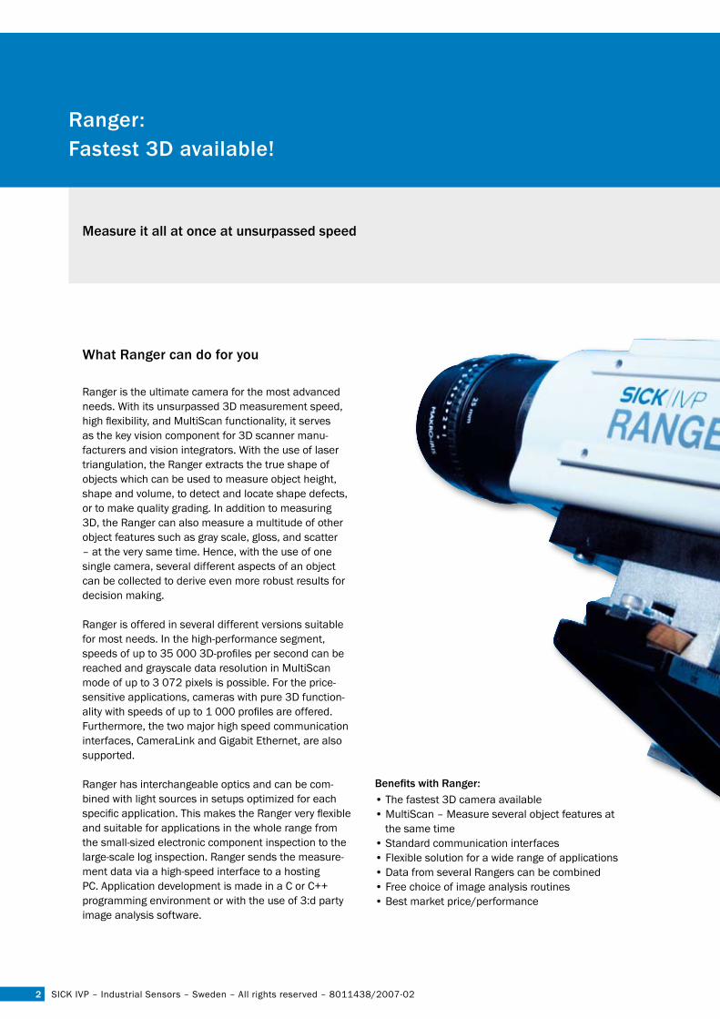
What ranger can do for you
Ranger is the ultimate camera for the most advanced needs. With its unsurpassed 3D measurement speed, high flexibility, and MultiScan functionality, it serves as the key vision component for 3D scanner manu-facturers and vision integrators. With the use of laser triangulation, the Ranger extracts the true shape of objects which can be used to measure object height, shape and volume, to detect and locate shape defects, or to make quality grading. In addition to measuring 3D, the Ranger can also measure a multitude of other object features such as gray scale, gloss, and scatter – at the very same time. Hence, with the use of one single camera, several different aspects of an object can be collected to derive even more robust results for decision making.
Ranger is offered in several different versions suitable for most needs. In the high-performance segment, speeds of up to 35 000 3D-profiles per second can be reached and grayscale data resolution in MultiScan mode of up to 3 072 pixels is possible. For the price-sensitive applications, cameras with pure 3D function-ality with speeds of up to 1 000 profiles are offered. Furthermore, the two major high speed communication interfaces, CameraLink and Gigabit Ethernet, are also supported.
Ranger has interchangeable optics and can be com-bined with light sources in setups optimized for each specific application. This makes the Ranger very flexible and suitable for applications in the whole range from the small-sized electronic component inspection to the large-scale log inspection. Ranger sends the measure-ment data via a high-speed interface to a hosting PC. Application development is made in a C or C++ programming environment or with the use of 3:d party image analysis software.
� SICK IVP – Industrial Sensors – Sweden – All rights reserved – 8011438/2007-02
Benefits with Ranger:• The fastest 3D camera available• MultiScan – Measure several object features at
the same time• Standard communication interfaces• Flexible solution for a wide range of applications• Data from several Rangers can be combined• Free choice of image analysis routines • Best market price/performance
applications
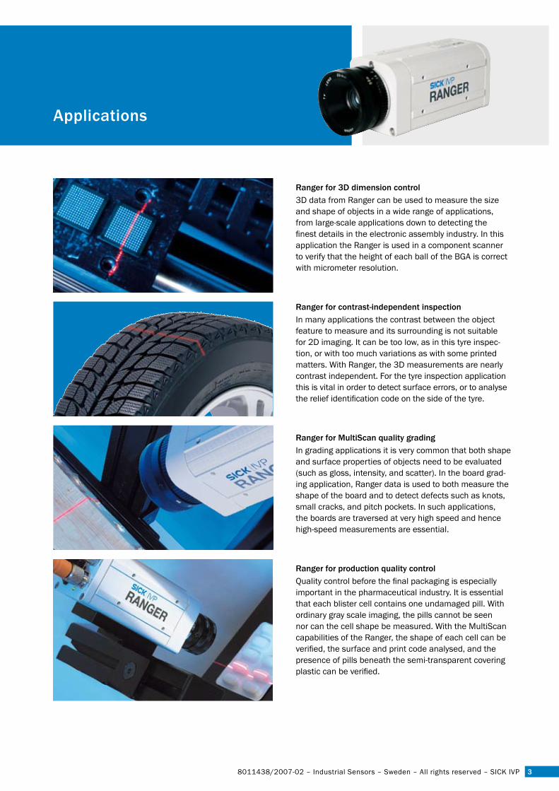
ranger for 3D dimension control3D data from Ranger can be used to measure the size and shape of objects in a wide range of applications, from large-scale applications down to detecting the finest details in the electronic assembly industry. In this application the Ranger is used in a component scanner to verify that the height of each ball of the BGA is correct with micrometer resolution.
ranger for contrast-independent inspectionIn many applications the contrast between the object feature to measure and its surrounding is not suitable for 2D imaging. It can be too low, as in this tyre inspec-tion, or with too much variations as with some printed matters. With Ranger, the 3D measurements are nearly contrast independent. For the tyre inspection application this is vital in order to detect surface errors, or to analyse the relief identification code on the side of the tyre.
ranger for Multiscan quality gradingIn grading applications it is very common that both shape and surface properties of objects need to be evaluated (such as gloss, intensity, and scatter). In the board grad-ing application, Ranger data is used to both measure the shape of the board and to detect defects such as knots, small cracks, and pitch pockets. In such applications, the boards are traversed at very high speed and hence high-speed measurements are essential.
ranger for production quality controlQuality control before the final packaging is especially important in the pharmaceutical industry. It is essential that each blister cell contains one undamaged pill. With ordinary gray scale imaging, the pills cannot be seen nor can the cell shape be measured. With the MultiScan capabilities of the Ranger, the shape of each cell can be verified, the surface and print code analysed, and the presence of pills beneath the semi-transparent covering plastic can be verified.
38011438/2007-02 – Industrial Sensors – Sweden – All rights reserved – SICK IVP
ändras
�
positionsfinder DMpLichtschranken Baureihe WL 27-2Lichtschranken Baureihe WL 27-2lichtschranken Baureihe Wl �7-�3D cameras: ranger
SICK IVP – Industrial Sensors – Sweden – All rights reserved – 8011438/2007-02
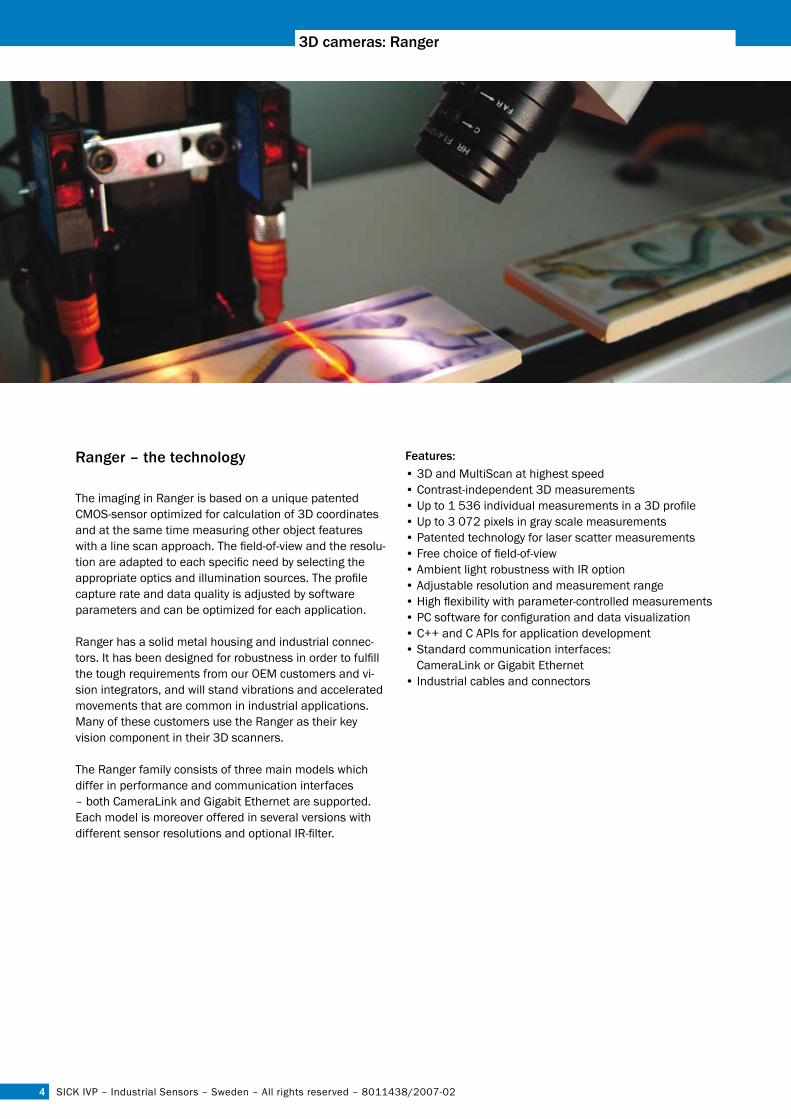
ranger – the technology
The imaging in Ranger is based on a unique patented CMOS-sensor optimized for calculation of 3D coordinates and at the same time measuring other object features with a line scan approach. The field-of-view and the resolu-tion are adapted to each specific need by selecting the appropriate optics and illumination sources. The profile capture rate and data quality is adjusted by software parameters and can be optimized for each application.
Ranger has a solid metal housing and industrial connec-tors. It has been designed for robustness in order to fulfill the tough requirements from our OEM customers and vi-sion integrators, and will stand vibrations and accelerated movements that are common in industrial applications. Many of these customers use the Ranger as their key vision component in their 3D scanners.
The Ranger family consists of three main models which differ in performance and communication interfaces – both CameraLink and Gigabit Ethernet are supported.Each model is moreover offered in several versions with different sensor resolutions and optional IR-filter.
Features:• 3D and MultiScan at highest speed• Contrast-independent 3D measurements• Up to 1 536 individual measurements in a 3D profile• Up to 3 072 pixels in gray scale measurements• Patented technology for laser scatter measurements• Free choice of field-of-view• Ambient light robustness with IR option• Adjustable resolution and measurement range• High flexibility with parameter-controlled measurements• PC software for configuration and data visualization • C++ and C APIs for application development• Standard communication interfaces:
CameraLink or Gigabit Ethernet• Industrial cables and connectors
�
ranger
8011438/2007-02 – Industrial Sensors – Sweden – All rights reserved – SICK IVP
ranger models
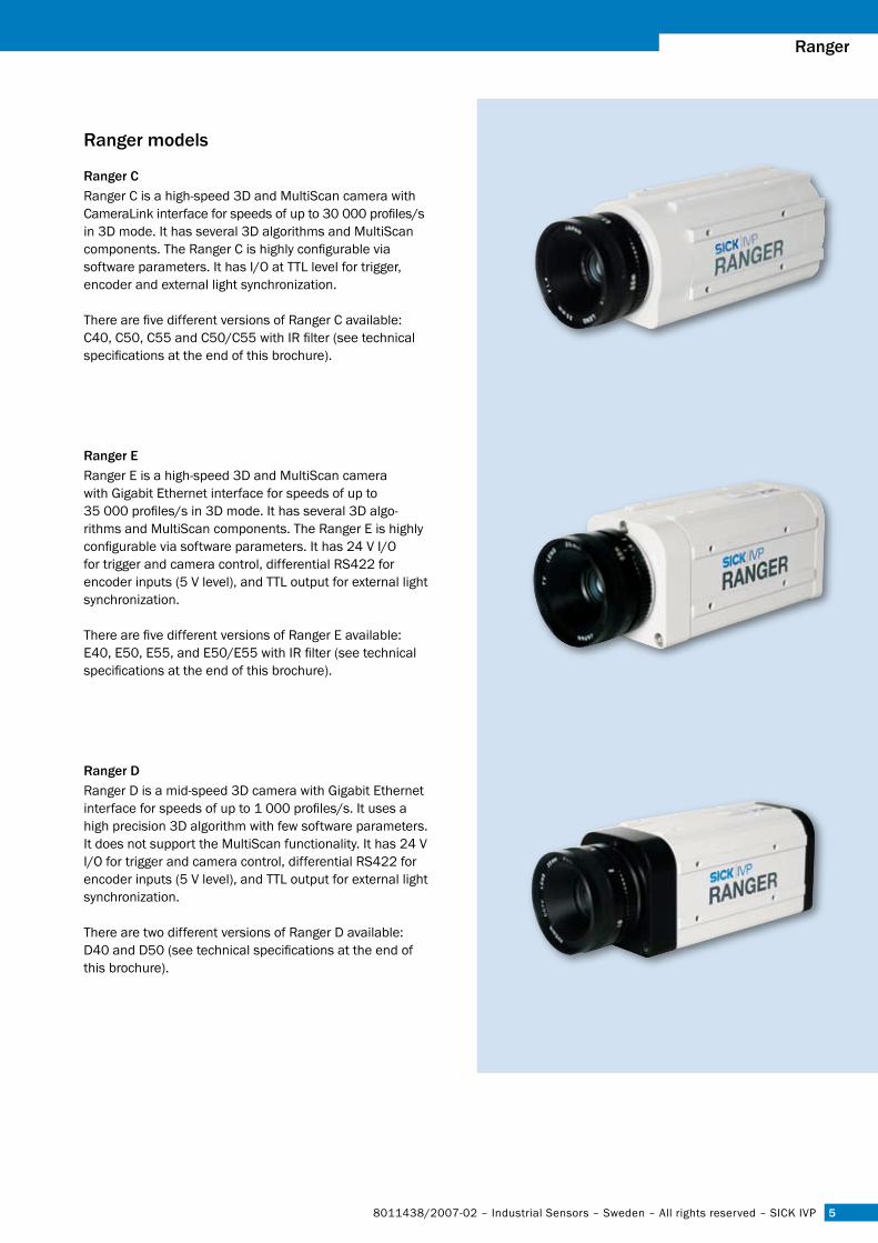
ranger cRanger C is a high-speed 3D and MultiScan camera with CameraLink interface for speeds of up to 30 000 profiles/s in 3D mode. It has several 3D algorithms and MultiScan components. The Ranger C is highly configurable via software parameters. It has I/O at TTL level for trigger, encoder and external light synchronization.
There are five different versions of Ranger C available: C40, C50, C55 and C50/C55 with IR filter (see technical specifications at the end of this brochure).
ranger eRanger E is a high-speed 3D and MultiScan camera with Gigabit Ethernet interface for speeds of up to 35 000 profiles/s in 3D mode. It has several 3D algo-rithms and MultiScan components. The Ranger E is highly configurable via software parameters. It has 24 V I/O for trigger and camera control, differential RS422 for encoder inputs (5 V level), and TTL output for external light synchronization.
There are five different versions of Ranger E available:E40, E50, E55, and E50/E55 with IR filter (see technical specifications at the end of this brochure).
ranger DRanger D is a mid-speed 3D camera with Gigabit Ethernet interface for speeds of up to 1 000 profiles/s. It uses a high precision 3D algorithm with few software parameters. It does not support the MultiScan functionality. It has 24 V I/O for trigger and camera control, differential RS422 for encoder inputs (5 V level), and TTL output for external light synchronization.
There are two different versions of Ranger D available: D40 and D50 (see technical specifications at the end of this brochure).
�
positionsfinder DMpLichtschranken Baureihe WL 27-2Lichtschranken Baureihe WL 27-2lichtschranken Baureihe Wl �7-�3D cameras: ranger
SICK IVP – Industrial Sensors – Sweden – All rights reserved – 8011438/2007-02
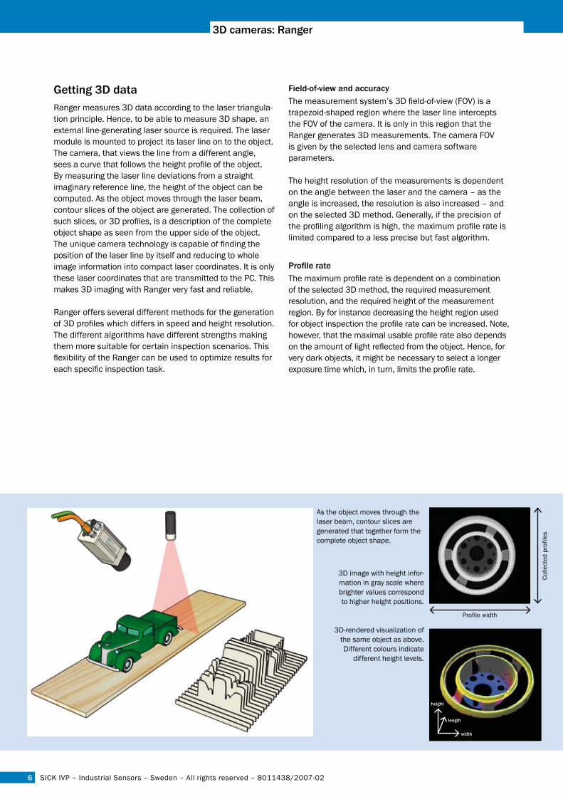
Getting 3D dataRanger measures 3D data according to the laser triangula-tion principle. Hence, to be able to measure 3D shape, an external line-generating laser source is required. The laser module is mounted to project its laser line on to the object. The camera, that views the line from a different angle, sees a curve that follows the height profile of the object. By measuring the laser line deviations from a straight imaginary reference line, the height of the object can be computed. As the object moves through the laser beam, contour slices of the object are generated. The collection of such slices, or 3D profiles, is a description of the complete object shape as seen from the upper side of the object. The unique camera technology is capable of finding the position of the laser line by itself and reducing to whole image information into compact laser coordinates. It is only these laser coordinates that are transmitted to the PC. This makes 3D imaging with Ranger very fast and reliable.
Ranger offers several different methods for the generation of 3D profiles which differs in speed and height resolution. The different algorithms have different strengths making them more suitable for certain inspection scenarios. This flexibility of the Ranger can be used to optimize results for each specific inspection task.
Field-of-view and accuracyThe measurement system’s 3D field-of-view (FOV) is a trapezoid-shaped region where the laser line intercepts the FOV of the camera. It is only in this region that the Ranger generates 3D measurements. The camera FOV is given by the selected lens and camera software parameters.
The height resolution of the measurements is dependent on the angle between the laser and the camera – as the angle is increased, the resolution is also increased – and on the selected 3D method. Generally, if the precision of the profiling algorithm is high, the maximum profile rate is limited compared to a less precise but fast algorithm.
Profile rateThe maximum profile rate is dependent on a combination of the selected 3D method, the required measurement resolution, and the required height of the measurement region. By for instance decreasing the height region used for object inspection the profile rate can be increased. Note, however, that the maximal usable profile rate also depends on the amount of light reflected from the object. Hence, for very dark objects, it might be necessary to select a longer exposure time which, in turn, limits the profile rate.
3D image with height infor-mation in gray scale where brighter values correspond to higher height positions.
3D-rendered visualization of the same object as above. Different colours indicate
different height levels.
As the object moves through the laser beam, contour slices are generated that together form the complete object shape.
Colle
cted
pro
files
Profile width
width
length
height

7
ranger
8011438/2007-02 – Industrial Sensors – Sweden – All rights reserved – SICK IVP
The Multiscan functionalityIn addition to measuring 3D, Ranger E and Ranger C are capable of measuring several other object properties at the very same time. This camera functionality is referred to as MultiScan. By adding appropriate light sources, several aspects of information about the object such as gloss, surface reflection, absorption in different wave-lengths, and laser scatter, can be measured. By combining these object features, very powerful and reliable object analysis applications can be developed, solving the most challenging inspection tasks. Moreover, since only one Ranger camera unit is needed for this, the solution and maintenance costs can be kept low.
All measurements in MultiScan mode, apart from 3D data, are acquired in a line scan manner. Each measurement, also referred to as component, uses its own part of the sensor where the external light source is measured. The parameters to control integration time etc. can be set independently of other components. The resulting data is then transmitted to individual buffers in the PC. The unique sensor in combination with the flexible configura-tion possibilities allows for up to ten different properties to be measured in parallel. The MultiScan configuration is set up via camera software parameters described in readable XML.
The intensity image of a board to the left and the scatter image (Tracheid) to the right. Note how the knots in the scatter image appear much darker than in the intensity image, thus making the knot identification much easier and more robust.
The intensity image of a blister pack to the left and the scatter image to the right. Note how two cells of the blister pack are much darker in the scatter image. This indicates that pills are missing in these cells, something which is not possible to conclude from the intensity image.
White light
Lasers
Scatter 3D measurementGrayscaleField-of-view
High resolution gray scale line (3072 pixels)
3D and line scan compo-nents area (1536 pixels)
In MultiScan, different parts of the sensor are assigned to different image components by software configura-tion. Any component combination is possible.
}
�
positionsfinder DMpLichtschranken Baureihe WL 27-2Lichtschranken Baureihe WL 27-2lichtschranken Baureihe Wl �7-�3D cameras: ranger
SICK IVP – Industrial Sensors – Sweden – All rights reserved – 8011438/2007-02
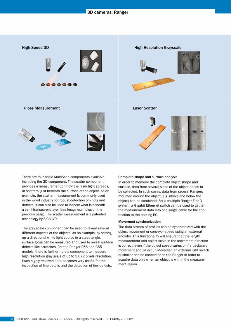
There are four basic MultiScan components available, including the 3D component. The scatter component provides a measurement on how the laser light spreads, or scatters, just beneath the surface of the object. As an example, the scatter measurement is commonly used in the wood industry for robust detection of knots and defects. It can also be used to inspect what is beneath a semi-transparent layer (see image examples on the previous page). The scatter measurement is a patented technology by SICK IVP.
The gray scale component can be used to reveal several different aspects of the objects. As an example, by setting up a directional white light source in a steep angle, surface gloss can be measured and used to reveal surface defects like scratches. For the Ranger E55 and C55 models, there is furthermore a component to measure high resolution gray scale of up to 3 072 pixels resolution. Such highly resolved data becomes very useful for the inspection of fine details and the detection of tiny defects.
complete shape and surface analysisIn order to measure the complete object shape and surface, data from several sides of the object needs to be collected. In such cases, data from several Rangers mounted around the object (e.g. above and below the object) can be combined. For a multiple Ranger E or D system, a Gigabit Ethernet switch can be used to gather the measurement data into one single cable for the con-nection to the hosting PC.
Movement synchronizationThe data stream of profiles can be synchronized with the object movement or conveyor speed using an external encoder. This functionality will ensure that the length measurement and object scale in the movement direction is correct, even if the object speed varies or if a backward movement should occur. Moreover, an external light switch or similar can be connected to the Ranger in order to acquire data only when an object is within the measure-ment region.
laser scatterGloss Measurement
high speed 3D high resolution Grayscale
�
ranger
8011438/2007-02 – Industrial Sensors – Sweden – All rights reserved – SICK IVP
application development
Having the Ranger as the data streaming component in a PC environment, very flexible and powerful solutions can be deveopled since both the performance of the PC and the selected image processing algorithms can be precisely selected. There are several third party software packages available on the market that can be used with Ranger to develop complete inspection solutions.
Ranger is incorporated into software applications for Windows XP using one of the two APIs included on the development software CD for Ranger: iCon C++ for use with C++ in Visual Studio .Net 2003/2005, and iCon C for use with C in for example Visual Studio 6.
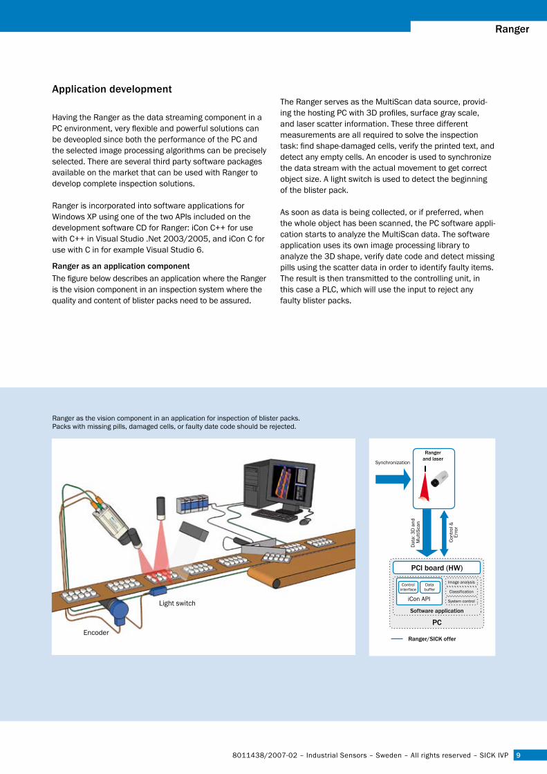
ranger as an application componentThe figure below describes an application where the Ranger is the vision component in an inspection system where the quality and content of blister packs need to be assured.
The Ranger serves as the MultiScan data source, provid-ing the hosting PC with 3D profiles, surface gray scale, and laser scatter information. These three different measurements are all required to solve the inspection task: find shape-damaged cells, verify the printed text, and detect any empty cells. An encoder is used to synchronize the data stream with the actual movement to get correct object size. A light switch is used to detect the beginning of the blister pack.
As soon as data is being collected, or if preferred, when the whole object has been scanned, the PC software appli-cation starts to analyze the MultiScan data. The software application uses its own image processing library to analyze the 3D shape, verify date code and detect missing pills using the scatter data in order to identify faulty items. The result is then transmitted to the controlling unit, in this case a PLC, which will use the input to reject any faulty blister packs.
Ranger as the vision component in an application for inspection of blister packs. Packs with missing pills, damaged cells, or faulty date code should be rejected.
Encoder
Light switch
10
positionsfinder DMpLichtschranken Baureihe WL 27-2Lichtschranken Baureihe WL 27-2lichtschranken Baureihe Wl �7-�3D cameras: ranger
SICK IVP – Industrial Sensors – Sweden – All rights reserved – 8011438/2007-02
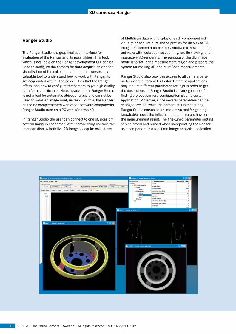
ranger studio
The Ranger Studio is a graphical user interface for evaluation of the Ranger and its possibilities. This tool, which is available on the Ranger development CD, can be used to configure the camera for data acquisition and for visualization of the collected data. It hence serves as a valuable tool to understand how to work with Ranger, to get acquainted with all the possibilities that the Ranger offers, and how to configure the camera to get high quality data for a specific task. Note, however, that Ranger Studio is not a tool for automatic object analysis and cannot be used to solve an image analysis task. For this, the Ranger has to be complemented with other software components. Ranger Studio runs on a PC with Windows XP.
In Ranger Studio the user can connect to one of, possibly, several Rangers connected. After establishing contact, the user can display both live 2D images, acquire collections
of MultiScan data with display of each component indi-vidually, or acquire pure shape profiles for display as 3D images. Collected data can be visualized in several differ-ent ways with tools such as zooming, profile viewing, and interactive 3D-rendering. The purpose of the 2D image mode is to setup the measurement region and prepare the system for making 3D and MultiScan measurements.
Ranger Studio also provides access to all camera para-meters via the Parameter Editor. Different applications may require different parameter settings in order to get the desired result. Ranger Studio is a very good tool for finding the best camera configuration given a certain application. Moreover, since several parameters can be changed live, i.e. while the camera still is measuring, Ranger Studio serves as an interactive tool for gaining knowledge about the influence the parameters have on the measurement result. The fine-tuned parameter setting can be saved and reused when incorporating the Ranger as a component in a real-time image analysis application.
11
ranger
8011438/2007-02 – Industrial Sensors – Sweden – All rights reserved – SICK IVP
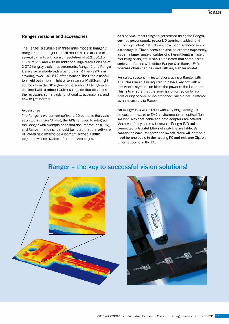
ranger versions and accessories
The Ranger is available in three main models: Ranger C, Ranger E, and Ranger D. Each model is also offered in several variants with sensor resolution of 512 x 512 or 1 536 x 512 and with an additional high resolution line of 3 072 for gray scale measurements. Ranger C and Ranger E are also available with a band pass IR filter (780 nm) covering rows 100–512 of the sensor. The filter is useful to shield out ambient light or to separate MultiScan light sources from the 3D region of the sensor. All Rangers are delivered with a printed Quickstart guide that describes the hardware, some basic functionality, accessories, and how to get started.
accessoriesThe Ranger development software CD contains the evalu-ation tool (Ranger Studio), the APIs required to integrate the Ranger with example code and documentation (SDK), and Ranger manuals. It should be noted that the software CD contains a lifetime development license. Future upgrades will be available from our web pages.
As a service, most things to get started using the Ranger, such as power supply, power I/O terminal, cables, and printed operating instructions, have been gathered in an accessory kit. These items can also be ordered separately, as can a large range of cables of different lengths, laser, mounting parts, etc. It should be noted that some acces-sories are for use with either Ranger C or Ranger E/D, whereas others can be used with any Ranger model.
For safety reasons, in installations using a Ranger with a 3B class laser, it is required to have a key box with a removable key that can block the power to the laser unit. This is to ensure that the laser is not turned on by acci-dent during service or maintenance. Such a box is offered as an accessory to Ranger.
For Ranger E/D when used with very long cabling dis-tances, or in extreme EMC environments, an optical fibre solution with fibre cable and opto adapters are offered. Moreover, for systems with several Ranger E/D units connected, a Gigabit Ethernet switch is available. By connecting each Ranger to the switch, there will only be a need for one cable to the hosting PC and only one Gigabit Ethernet board in the PC.
ranger – the key to successful vision solutions!
1�
positionsfinder DMpLichtschranken Baureihe WL 27-2Lichtschranken Baureihe WL 27-2lichtschranken Baureihe Wl �7-�3D cameras: ranger
SICK IVP – Industrial Sensors – Sweden – All rights reserved – 8011438/2007-02
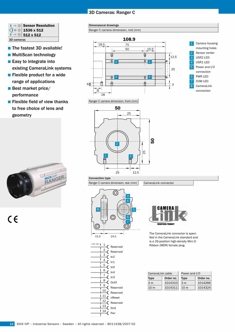
■The fastest 3D available!■Multiscan technology■easy to integrate into existing cameralink systems■Flexible product for a wide range of applications■Best market price/ performance■Flexible field of view thanks to free choice of lens and geometry
3D cameras
Sensor Resolution 1536 x 512512 x 512
Dimensional drawings
connection type
6
1128
3
25
12.5
50 15.575
108.9 18.5
25
25
25
50
50
12.5 15.5 24.5
Ranger C camera dimension, mid (mm)
The CameraLink connector is speci-fied in the CameraLink standard and is a 26-position high-density Mini D Ribbon (MDR) female plug.
Camera housing mounting holes Sensor center USR2 LED USR1 LED Power and I/0 connection PWR LED COM LED CameraLink connection
345
78
In2
1Reserved
Reserved2
3
4
5In1
In0
Out0
6In4
In37
8
9
10Reserved
Reserved
Reserved
nReset11
12
13
14Gnd
Pwr
Ranger C camera dimension, front (mm)
Ranger C camera dimension, rear (mm) CameraLink connector
15.5 24.5
34
5
7
8
3D cameras: ranger c
CameraLink cableType order no. 3 m 101431010 m 1014311
Power and I/O Type order no. 3 m 101426610 m 1014324
13
ranger
8011438/2007-02 – Industrial Sensors – Sweden – All rights reserved – SICK IVP
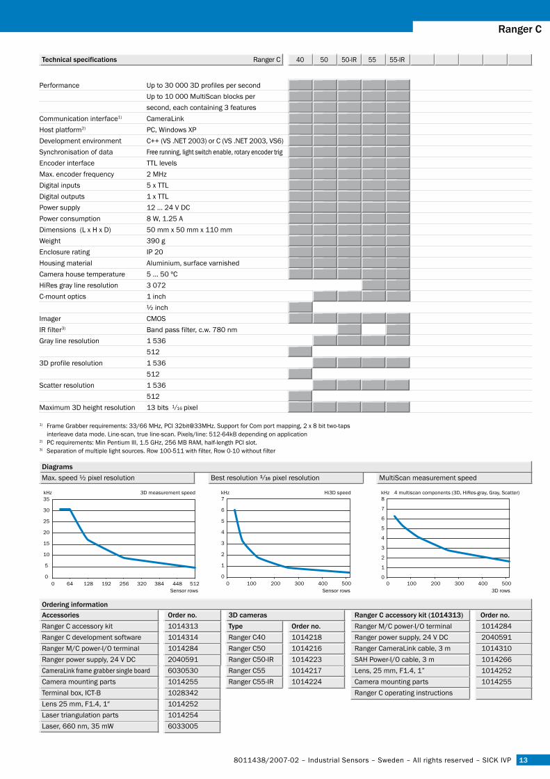
Technical specifications Ranger C 40 50 50-IR 55 55-IR
Diagrams
ordering information
7
6
5
4
3
2
1
00 100 200 300 400 500
kHz
Sensor rows
8
7
6
5
4
3
2
1
00 100 200 300 400 500
kHz
3D rows
35
30
25
20
15
10
5
00 64 128 192 256 320 512384 448
kHz
Sensor rows
3D measurement speed Hi3D speed 4 multiscan components (3D, HiRes-gray, Gray, Scatter)
Best resolution pixel resolution MultiScan measurement speed Max. speed ½ pixel resolution
3D camerasType order no.Ranger C40 1014218Ranger C50 1014216Ranger C50-IR 1014223Ranger C55 1014217Ranger C55-IR 1014224
1) Frame Grabber requirements: 33/66 MHz, PCI 32bit@33MHz. Support for Com port mapping, 2 x 8 bit two-taps interleave data mode. Line-scan, true line-scan. Pixels/line: 512-64kB depending on application2) PC requirements: Min Pentium III, 1.5 GHz, 256 MB RAM, half-length PCI slot.3) Separation of multiple light sources. Row 100-511 with filter, Row 0-10 without filter
1/1�
ranger c
Performance Up to 30 000 3D profiles per second Up to 10 000 MultiScan blocks per second, each containing 3 features Communication interface1) CameraLinkHost platform2) PC, Windows XP Development environment C++ (VS .NET 2003) or C (VS .NET 2003, VS6)Synchronisation of data Free running, light switch enable, rotary encoder trigEncoder interface TTL levelsMax. encoder frequency 2 MHzDigital inputs 5 x TTLDigital outputs 1 x TTLPower supply 12 ... 24 V DCPower consumption 8 W, 1.25 ADimensions (L x H x D) 50 mm x 50 mm x 110 mmWeight 390 gEnclosure rating IP 20Housing material Aluminium, surface varnishedCamera house temperature 5 ... 50 ºCHiRes gray line resolution 3 072C-mount optics 1 inch ½ inchImager CMOSIR filter3) Band pass filter, c.w. 780 nmGray line resolution 1 536 5123D profile resolution 1 536 512Scatter resolution 1 536 512Maximum 3D height resolution 13 bits pixel
accessories order no.Ranger C accessory kit 1014313Ranger C development software 1014314Ranger M/C power-I/O terminal 1014284Ranger power supply, 24 V DC 2040591CameraLink frame grabber single board 6030530Camera mounting parts 1014255Terminal box, ICT-B 1028342Lens 25 mm, F1.4, 1″ 1014252Laser triangulation parts 1014254Laser, 660 nm, 35 mW 6033005
ranger c accessory kit (101�313) order no.Ranger M/C power-I/O terminal 1014284Ranger power supply, 24 V DC 2040591Ranger CameraLink cable, 3 m 1014310SAH Power-I/O cable, 3 m 1014266Lens, 25 mm, F1.4, 1” 1014252Camera mounting parts 1014255Ranger C operating instructions
1/16
1�
positionsfinder DMpLichtschranken Baureihe WL 27-2Lichtschranken Baureihe WL 27-2lichtschranken Baureihe Wl �7-�3D cameras: ranger
SICK IVP – Industrial Sensors – Sweden – All rights reserved – 8011438/2007-02
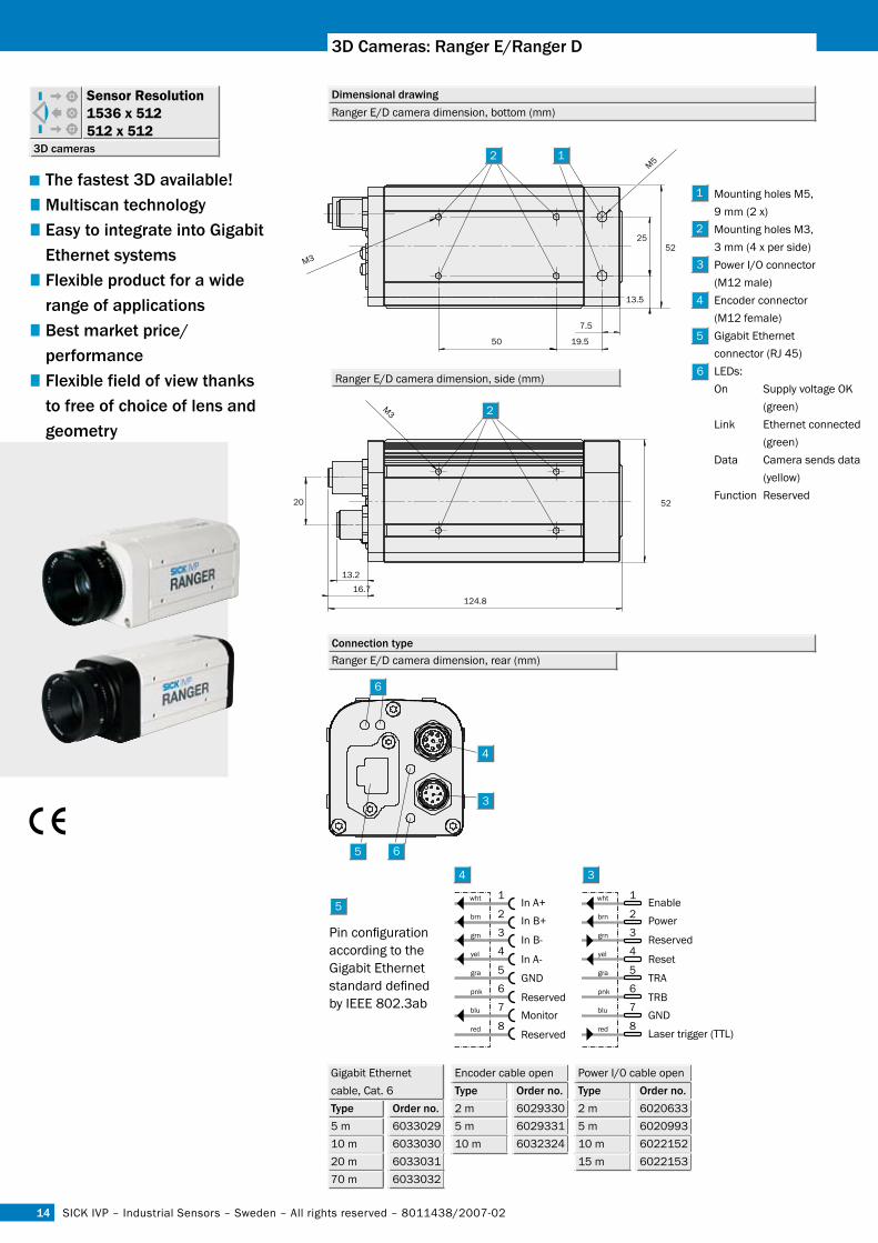
■The fastest 3D available!■ Multiscan technology■ easy to integrate into Gigabit ethernet systems■ Flexible product for a wide range of applications■ Best market price/ performance■ Flexible field of view thanks to free of choice of lens and geometry
3D cameras
Sensor Resolution 1536 x 512512 x 512
Dimensional drawing
connection type
Ranger E/D camera dimension, bottom (mm)
3
4
5
Ranger E/D camera dimension, side (mm)
Ranger E/D camera dimension, rear (mm)
3D cameras: ranger e/ranger D
5
4 3
Reserved
1Enable
Power2
3
4
5
6
7
8
Reset
TRA
TRBGND
Laser trigger (TTL)
wht
brn
grn
yel
gra
pnk
blu
red
In B-
1In A+
In B+2
3
4
5
6
7
8
In A-
GND
ReservedMonitor
Reserved
wht
brn
grn
yel
gra
pnk
blu
red
Pin configuration according to the Gigabit Ethernet standard defined by IEEE 802.3ab
Encoder cable openType order no. 2 m 60293305 m 602933110 m 6032324
Power I/0 cable openType order no.2 m 6020633 5 m 602099310 m 602215215 m 6022153
Gigabit Ethernet cable, Cat. 6Type order no. 5 m 603302910 m 603303020 m 603303170 m 6033032
4
3
5
Mounting holes M5, 9 mm (2 x)Mounting holes M3, 3 mm (4 x per side) Power I/O connector (M12 male)Encoder connector (M12 female)Gigabit Ethernet connector (RJ 45)LEDs: On Supply voltage OK (green)Link Ethernet connected (green)Data Camera sends data (yellow)Function Reserved
19.5
13.5
50
M352
25
7.5
20 52
16.7124.8
13.2
M5
M3
1�
ranger
8011438/2007-02 – Industrial Sensors – Sweden – All rights reserved – SICK IVP
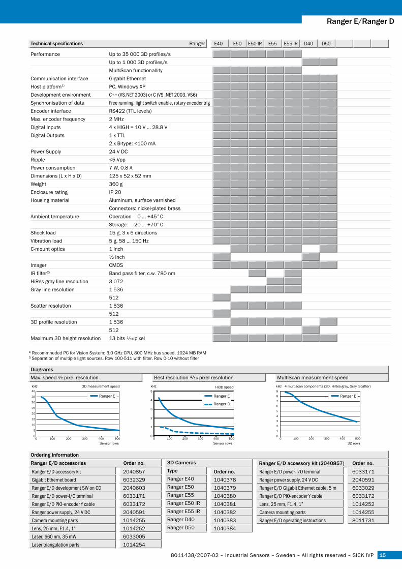
Technical specifications Ranger E40 E50 E50-IR E55 E55-IR D40 D50
Diagrams
ordering information
0 100 200 300 400 5000
5
10
15
20
25
30
35
40
0 100 200 300 400 5000
1
2
3
4
5
0 100 200 300 400 5000
1
2
3
4
5
6
7
8
9
Ranger E Ranger E Ranger E
Ranger D
Sensor rows 3D rowsSensor rows
3D measurement speedkHz kHz kHz Hi3D speed 4 multiscan components (3D, HiRes-gray, Gray, Scatter)
Best resolution pixel resolution MultiScan measurement speed Max. speed ½ pixel resolution
1) Recommneded PC for Vision System: 3.0 GHz CPU, 800 MHz bus speed, 1024 MB RAM 2) Separation of multiple light sources. Row 100-511 with filter. Row 0-10 without filter
1/1�
ranger e/ranger D
Performance Up to 35 000 3D profiles/s Up to 1 000 3D profiles/s MultiScan functionallityCommunication interface Gigabit EthernetHost platform1) PC, Windows XPDevelopment environment C++ (VS.NET 2003) or C (VS .NET 2003, VS6)Synchronisation of data Free running, light switch enable, rotary encoder trigEncoder interface RS422 (TTL levels)Max. encoder frequency 2 MHzDigital Inputs 4 x HIGH = 10 V … 28.8 VDigital Outputs 1 x TTL 2 x B-type; <100 mAPower Supply 24 V DCRipple <5 VppPower consumption 7 W, 0.8 ADimensions (L x H x D) 125 x 52 x 52 mmWeight 360 gEnclosure rating IP 20Housing material Aluminum, surface varnished Connectors: nickel-plated brassAmbient temperature Operation 0 … +45°C Storage: –20 … +70°CShock load 15 g, 3 x 6 directionsVibration load 5 g, 58 … 150 HzC-mount optics 1 inch ½ inchImager CMOSIR filter2) Band pass filter, c.w. 780 nmHiRes gray line resolution 3 072Gray line resolution 1 536 512Scatter resolution 1 536 5123D profile resolution 1 536 512Maximum 3D height resolution 13 bits pixel
3D camerasTypeRanger E40Ranger E50Ranger E55Ranger E50 IRRanger E55 IRRanger D40Ranger D50
order no.10403781040379104038010403811040382 10403831040384
accessories
Ranger E/D accessory kitGigabit Ethernet boardRanger E/D development SW on CDRanger E/D power-I/O terminalRanger E/D PIO-encoder Y cableRanger power supply, 24 V DCCamera mounting partsLens, 25 mm, F1.4, 1”Laser, 660 nm, 35 mWLaser triangulation parts
2040857603232920406036033171603317220405911014255101425260330051014254
ranger e/D accessories order no. ranger e/D accessory kit (�0�0��7) order no.Ranger E/D power-I/O terminalRanger power supply, 24 V DCRanger E/D Gigabit Ethernet cable, 5 mRanger E/D PIO-encoder Y cableLens, 25 mm, F1.4, 1”Camera mounting partsRanger E/D operating instructions
6033171204059160330296033172101425210142558011731
1/16
Mounting holes M5, 9 mm (2 x)Mounting holes M3, 3 mm (4 x per side) Power I/O connector (M12 male)Encoder connector (M12 female)Gigabit Ethernet connector (RJ 45)LEDs: On Supply voltage OK (green)Link Ethernet connected (green)Data Camera sends data (yellow)Function Reserved
australiaPhone +61 3 9497 4100 1800 33 48 02 – tollfreeE-Mail [email protected]
Belgium/luxembourgPhone +32 (0)2 466 55 66E-Mail [email protected]
BrasilPhone +55 11 5091-4900E-Mail [email protected]
ceská republikaPhone +420 2 57 91 18 50E-Mail [email protected]
chinaPhone +852-2763 6966E-Mail [email protected]
DanmarkPhone +45 45 82 64 00E-Mail [email protected]
DeutschlandPhone +49 (0)2 11 53 01-250E-Mail [email protected]
españaPhone +34 93 480 31 00E-Mail [email protected]
FrancePhone +33 1 64 62 35 00E-Mail [email protected]
Great BritainPhone +44 (0)1727 831121E-Mail [email protected]
indiaPhone +91–22–2822 7084E-Mail [email protected]
italiaPhone +39 02 27 43 41E-Mail [email protected]
JapanPhone +81 (0)3 3358 1341E-Mail [email protected]
nederlandsPhone +31 (0)30 229 25 44E-Mail [email protected]
norge Phone +47 67 81 50 00E-Mail [email protected]
ÖsterreichPhone +43 (0)22 36 62 28 8-0E-Mail [email protected]
polskaPhone +48 22 837 40 50E-Mail [email protected]
republic of KoreaPhone +82-2 786 6321/4E-Mail [email protected]
Republika SlowenijaPhone +386 (0)1-47 69 990E-Mail [email protected]
russiaPhone +7 495 775 05 34E-Mail [email protected]
SchweizPhone +41 41 619 29 39E-Mail [email protected]
singaporePhone +65 6744 3732E-Mail [email protected]
suomiPhone +358-9-25 15 800E-Mail [email protected]
sverigePhone +46 8 680 64 50E-Mail [email protected]
TaiwanPhone +886 2 2365-6292E-Mail [email protected]
TürkiyePhone +90 216 587 74 00E-Mail [email protected]
Usa/canada/MéxicoPhone +1(952) 941-6780 1 800-325-7425 – tollfreeE-Mail [email protected]
More representatives and agencies in all major industrial nations at www.sick.com
8011
438/
2007
-02-
07 ∙
ARIO
M/C
T ∙ P
rinte
d in
Sw
eden
(200
6-10
) ∙ S
ubje
ct to
cha
nge
with
out n
otic
e ∙ T
he s
peci
fied
prod
uct f
eatu
res
and
tech
nica
l dat
a do
not
repr
esen
t any
gua
rant
ee ∙
IVP
A4 4
c in
t27
SICK IVP | Linköping | Sweden | www.sickivp.comSICK AG | Waldkirch | Germany | www.sick.com