Range Rover Electrical Library - LM - 2nd Edition - Englandy.ee/manuals/electricity/Electronic...
494
Electrical Library
Transcript of Range Rover Electrical Library - LM - 2nd Edition - Englandy.ee/manuals/electricity/Electronic...

Electrical Library
NRRERL 28/11/01 10:02 am Page 1
ELECTRICAL LIBRARY
LRL 0453ENG(2)Published by Land Rover
© Land Rover 2002All rights reserved. No part of this publication may be reproduced, stored in a retrieval system or transmitted in any form, electronic, mechanical,
recording or other means without prior written permission from Land Rover.


CONTENTS
INTRODUCTION ............................................................................. 1ABOUT THIS DOCUMENT ............................................................................... 1.1ELECTRICAL PRECAUTIONS ......................................................................... 1.3ABBREVIATIONS ............................................................................................. 1.6HOW TO USE THIS DOCUMENT .................................................................... 1.8FAULT DIAGNOSIS ........................................................................................ 1.10WIRE COLOUR CODES ................................................................................. 1.11
FUSE DETAILS ............................................................................... 2ENGINE COMPARTMENT FUSE BOX ............................................................ 2.2PASSENGER COMPARTMENT FUSE BOX .................................................... 2.3REAR FUSE BOX ............................................................................................. 2.6
EARTH POINTS AND HEADERS ................................................... 3
DESCRIPTION AND OPERATION ................................................. 4ANTI-THEFT ALARM AND CENTRAL DOOR LOCKING (CDL) ...................... 4.1ENGINE IMMOBILISATION .............................................................................. 4.9WINDOWS ...................................................................................................... 4.13SUNROOF ...................................................................................................... 4.17DOOR MIRRORS ............................................................................................ 4.19INTERIOR MIRROR ........................................................................................ 4.23FRONT SEATS ............................................................................................... 4.25FRONT HEATED SEATS ................................................................................ 4.28REAR HEATED SEATS .................................................................................. 4.29DIAGNOSTIC SOCKET .................................................................................. 4.30STARTING AND CHARGING – Td6 ............................................................... 4.31STARTING AND CHARGING – V8 ................................................................. 4.35CRUISE CONTROL ........................................................................................ 4.38ELECTRONIC AUTOMATIC TRANSMISSION (EAT) – GM5 ......................... 4.40ELECTRONIC AUTOMATIC TRANSMISSION (EAT) – ZF ........................... 4.43ANTI-LOCK BRAKING SYSTEM (ABS) .......................................................... 4.46SUPPLEMENTARY RESTRAINT SYSTEM (SRS) ......................................... 4.49AUTOMATIC TEMPERATURE CONTROL (ATC) .......................................... 4.53AUTOMATIC TEMPERATURE CONTROL (ATC) – COMFORT .................... 4.56FUEL BURNING HEATER – Td6 .................................................................... 4.61FUEL BURNING HEATER – V8 ...................................................................... 4.62COOLING FAN ................................................................................................ 4.64
RANGE ROVER 1
HEATED REAR WINDOW (HRW) .................................................................. 4.66

CONTENTS
HEATED FRONT SCREEN (HFS) .................................................................. 4.67WIPERS AND WASHERS .............................................................................. 4.68HEADLAMP WASH/WIPE ............................................................................... 4.71BRAKE AND REVERSE LAMPS .................................................................... 4.72HEAD, SIDE AND TAIL LAMPS ...................................................................... 4.74AUTOMATIC HEADLAMP LEVELLING .......................................................... 4.78FOG LAMPS ................................................................................................... 4.80DIRECTION INDICATOR/HAZARD WARNING LAMPS ................................. 4.82INTERIOR LAMPS .......................................................................................... 4.84INTERIOR ILLUMINATION ............................................................................. 4.87INSTRUMENTS .............................................................................................. 4.90HORNS ........................................................................................................... 4.92CLOCK ............................................................................................................ 4.93CIGAR LIGHTERS .......................................................................................... 4.94ACCESSORY SOCKETS ................................................................................ 4.95TRAILER SOCKET ......................................................................................... 4.96AUDIO SYSTEM – LOW LINE ........................................................................ 4.98AUDIO SYSTEM – MID-LINE ......................................................................... 4.99AUDIO SYSTEM – HIGH LINE ..................................................................... 4.100SATELLITE NAVIGATION SYSTEM ............................................................ 4.101SATELLITE NAVIGATION SYSTEM – NAS ................................................. 4.102TELEPHONE ................................................................................................. 4.103TELEPHONE – HANDS FREE ......................................................................4.104TELEPHONE – NAS ......................................................................................4.105FUEL PUMP ...................................................................................................4.106ROTARY COUPLER ......................................................................................4.108PARK DISTANCE CONTROL (PDC) .............................................................4.110TYRE PRESSURE MONITORING (TPM) ......................................................4.113STEERING COLUMN .................................................................................... 4114AIR SUSPENSION ........................................................................................ 4.117
CONNECTOR .................................................................................. 5CIRCUIT REFERENCE NUMBERS .................................................................. 5.1
2 RANGE ROVER
INTRODUCTION
INTRODUCTION
ABOUT THIS DOCUMENTGeneralThis document is intended to assist in diagnosing electrical faults, and should be used in conjunction with the Electrical Circuit Diagrams. The document is divided into the following sections.
1. INTRODUCTION – Includes Electrical Precautions, a list of Abbreviations and general information on how to use this document.
2. FUSE DETAILS – Provides details of location, rating in Amperes, and circuit(s) protected.
3. EARTH POINTS AND HEADERS – Provides details of earth points and earth headers, including a plan view of the vehicle to aid location.
4. DESCRIPTION AND OPERATION – Provides an explanation of how each of the systems operate.
5. CIRCUIT REFERENCE NUMBERS – Provides a list of circuit reference numbers against a model or feature to which they apply.
6. CONNECTOR DETAIL – Details of connectors including a location photograph, face view and pin-out table.
NOTE: Before starting electrical checks on the vehicle, ensure that relevant mechanical functions operate satisfactorily.
ReferencesReferences to the LH or RH side given in this document are made when viewing the vehicle from the rear.
Operations covered in this document do not include reference to testing the vehicle after repair. It is essential that work is inspected and tested after completion and, if necessary, a road test of the vehicle is undertaken, particularly where safety related items are concerned.
CAUTION: Before undertaking any electrical work on a vehicle ALWAYS read the ELECTRICAL PRECAUTIONS.
RANGE ROVER 1.1
INTRODUCTION
Battery VoltageOpen Circuit Voltage TestBefore commencing diagnosis of electrical problems, verify the condition of the battery is acceptable by using the open circuit voltage test.
1. Switch off all electrical loads on the vehicle.2. Adjust digital multimeter to read dc volts on the appropriate scale.3. Connect test probes across battery terminals ensuring that polarity is correct and
record the voltage displayed.
A reading of 12.5 V or more is acceptable; any battery which reads less than this will need charging.
NOTE: If the vehicle has been used within a period of 8 hours prior to the test, surface charge must be removed from the battery by switching the headlamps on for approximately 30 seconds. Wait a further 60 seconds before checking the open circuit voltage.
Battery voltage is used as a known reference for ascertaining whether or not circuits are receiving sufficiently high voltage for components to function correctly. This reference is only a guide since most electronic circuits are designed to function over a wide range of voltages. In addition, consideration must be given to readings affected by voltage drop across certain components and fluctuations due to cable lengths.
1.2 RANGE ROVER

INTRODUCTION
ELECTRICAL PRECAUTIONSGeneralThe following guidelines are intended to ensure the safety of the operator whilst preventing damage to the electrical and electronic components fitted to the vehicle. Where necessary, specific precautions are detailed in the relevant sections of this document, reference to these precautions should be made prior to commencing repair operations.
Equipment – Prior to commencing any test procedure on the vehicle, ensure that the relevant test equipment is working correctly and any harnesses or connections are in good condition. This particularly applies to mains lead or connections.
WARNING: Before commencing work on an ignition system, all high tension terminals, adaptors and diagnostic equipment for testing should be inspected to ensure that they are adequately insulated and shielded to prevent accidental personal contact and to minimise the risk of shock. Wearers of surgically implanted pacemaker devices should not work in close proximity to ignition circuits or diagnostic equipment.
Polarity – Never reverse connect the vehicle battery and always observe correct polarity when connecting test equipment.
High Voltage Circuits – Whenever disconnecting live ht circuits, always use insulated pliers and never allow the open end of the ht lead to come into contact with other components, particularly ECU's. Since high voltage spikes can occur on the terminals of the coil while the engine is running, exercise caution when measuring the voltage at these points.
WARNING: The Xenon headlamp system generates up to 28,000 V and contact with this voltage could lead to fatality. Make sure that the headlamps are switched off before working on the system. Refer to the guidelines given in the 'General Information' section of the Service Repair Procedures Workshop Manual before any work is carried out.
Connectors and Harnesses – The engine compartment of a vehicle is a particularly hostile environment for electrical components and connectors. Always ensure these items are dry and oil free before disconnecting and connecting test equipment. Never force connectors apart either by using tools or by pulling on the wiring harness. Always ensure locking tabs are disengaged before removal and note orientation to enable correct reconnection. Ensure that any protective covers and substances are replaced if disturbed.
RANGE ROVER 1.3

INTRODUCTION
Before removing a faulty component, refer to the Workshop Manual for removal procedures. Ensure the ignition switch is turned to the 'OFF' position, the battery is disconnected (see Battery Disconnecting) and any disconnected harnesses are supported to avoid any undue strain at the terminals. When replacing the component keep oily hands away from electrical connection areas and push connectors home until any locking tabs fully engage.
Battery DisconnectingIt is imperative that the key is removed from the ignition switch before disconnecting the battery. A time of 2 minutes must also elapse (after the ignition has been switched off) before the battery should be disconnected. Failure to do so could result in:
Navigation computer software damage Incorrect fuel gauge reading.
Before disconnecting the battery, disable the alarm system and switch off all electrical equipment. If the radio is to be serviced, ensure the security code has been deactivated.
CAUTION: Never disconnect the battery with the ignition switched on.
CAUTION: To prevent damage to the navigation computer software, a waiting period of two minutes must elapse after the ignition is switched off before the battery leads are disconnected.
CAUTION: To prevent damage to electrical components, always disconnect the battery when working on the vehicle's electrical system. The earth lead must be disconnected first and reconnected last.
CAUTION: Always ensure that battery leads are routed correctly and are not close to any potential chafing points.
After reconnecting the battery, the steering wheel must be turned to full LH and RH lock (with the engine running). This allows the Dynamic Stability Control (DSC) system to relearn the steering wheel position. Failure to do so will result in a variety of instrument pack warning lamps being illuminated.
1.4 RANGE ROVER

INTRODUCTION
Battery ChargingOnly recharge the battery with it removed from the vehicle. Always ensure any battery charging area is well ventilated and that every precaution is taken to avoid naked flames and sparks.
The New Range Rover is fitted with a lead calcium battery, and can only be charged using equipment specifically designed to operate on this type of battery. Refer to the Land Rover Equipment bulletin for a list of recommended battery charging equipment.
DisciplinesSwitch off ignition prior to making any connection or disconnection in the system as electrical surge caused by disconnecting 'live' connections can damage electrical components.
Ensure hands and work surfaces are clean and free of grease, swarf, etc. as grease collects dirt which can cause tracking or high-resistance contacts.
When handling printed circuit boards, treat them as you would a disc – hold by the edges only; note that some electrical components are susceptible to body static.
Connectors should never be subjected to forced removal or refit, especially inter-board connectors. Damaged contacts will cause short-circuit and open-circuit conditions.
Prior to commencing testing, and periodically during testing, touch a good earth, i.e. cigar lighter socket, to discharge body static as some electrical components are vulnerable to static electricity.
Grease for Electrical ConnectorsSome under bonnet and under body connectors are protected against corrosion by the application of a special grease during production. Should connectors of this type be disturbed, repaired, or replaced, a grease of this type, available under part number BAU 5811, should again be applied. Do not apply grease to any connectors that do not have grease applied as standard.
NOTE: The use of other greases must be avoided as they can migrate into relays, switches, etc. contaminating the contacts and leading to intermittent operation or failure.
RANGE ROVER 1.5
INTRODUCTION
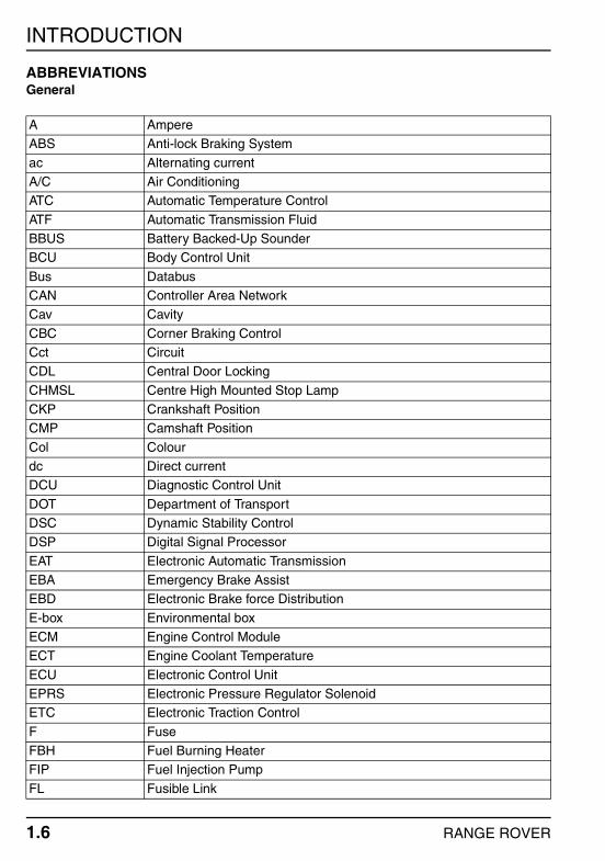
ABBREVIATIONSGeneral
A AmpereABS Anti-lock Braking System
ac Alternating currentA/C Air ConditioningATC Automatic Temperature Control
ATF Automatic Transmission Fluid BBUS Battery Backed-Up Sounder BCU Body Control Unit
Bus Databus CAN Controller Area Network Cav Cavity
CBC Corner Braking Control Cct Circuit CDL Central Door Locking
CHMSL Centre High Mounted Stop Lamp CKP Crankshaft PositionCMP Camshaft Position
Col Colour dc Direct current DCU Diagnostic Control Unit
DOT Department of TransportDSC Dynamic Stability Control DSP Digital Signal Processor
EAT Electronic Automatic Transmission EBA Emergency Brake Assist EBD Electronic Brake force Distribution
E-box Environmental boxECM Engine Control Module ECT Engine Coolant Temperature
ECU Electronic Control Unit EPRS Electronic Pressure Regulator SolenoidETC Electronic Traction Control
F Fuse FBH Fuel Burning Heater FIP Fuel Injection Pump
FL Fusible Link
1.6 RANGE ROVER
INTRODUCTION
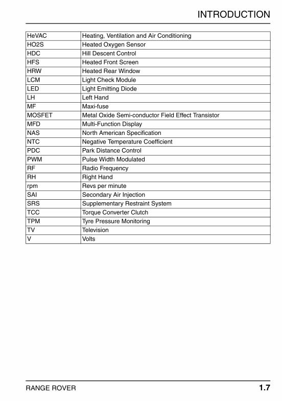
HeVAC Heating, Ventilation and Air ConditioningHO2S Heated Oxygen Sensor
HDC Hill Descent Control HFS Heated Front Screen HRW Heated Rear Window
LCM Light Check Module LED Light Emitting Diode LH Left Hand
MF Maxi-fuse MOSFET Metal Oxide Semi-conductor Field Effect TransistorMFD Multi-Function Display
NAS North American Specification NTC Negative Temperature Coefficient PDC Park Distance Control
PWM Pulse Width Modulated RF Radio Frequency RH Right Hand
rpm Revs per minute SAI Secondary Air InjectionSRS Supplementary Restraint System
TCC Torque Converter Clutch TPM Tyre Pressure Monitoring TV Television
V Volts
RANGE ROVER 1.7

INTRODUCTION
HOW TO USE THIS DOCUMENTFuse DetailsContains information on fuse functions and values and should be used together with the power distribution circuit diagrams to establish which systems share a common power supply and to ensure that correct value fuses are fitted.
Earth Points and HeadersShows a plan view of the vehicle with location of all earth points. Supporting photographs and connector detail information appear in the Connector section.
Description and OperationPresented in the same order as the circuit diagrams in the Electrical Circuit Diagrams publication, each of the descriptions contains a brief overview of the main system functions and includes reference to the appropriate wire colours. Always read this section before starting work on a system so that a good understanding of system functionality is obtained.
Connector DetailsThis section is effectively an index of every electrical connector on the vehicle, including headers and eyelets. A page is dedicated to each connector, with the information presented in a standard format. The connector number is displayed on each page header to ease reference. Connector information comprises:
Connector Number – The assigned number, prefixed 'C'. Connector Name – Usually derived from the component to which the connection is
made. Male/Female – If applicable, identifies the gender of the connector pins (NOT the
housing) as Male or Female. Generally, connectors mating directly into a component have Female pins.
Colour – If applicable, the colour of the connector housing is shown. NATURAL is used to describe connectors with a clear/translucent plastic finish.
Location Statement – Used in conjunction with the photograph to determine the location of the connector.
Photograph – Shows the location of the subject connector. In most cases the photograph will indicate the amount of trim removal necessary to reveal the connector. For convenience some photographs identify more than one connector.
Face View – An outline of the connector housing, viewed from the front, showing pin numbers (if applicable).
Pin-out Table – A three column table, detailing the colour and position of each wire in the connector:
1.8 RANGE ROVER
INTRODUCTION
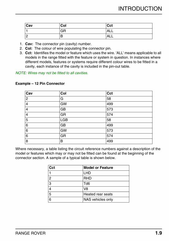
1. Cav: The connector pin (cavity) number.2. Col: The colour of wire populating the connector pin.3. Cct: Identifies the model or feature which uses the wire. 'ALL' means applicable to all
models in the range fitted with the feature or system in question. In instances where different models, features or systems require different colour wires to be fitted in a cavity, each instance of the cavity is included in the pin-out table.
NOTE: Wires may not be fitted to all cavities.
Example – 12 Pin Connector
Where necessary, a table listing the circuit reference numbers against a description of the model or features which may or may not be fitted can be found at the beginning of the connector section. A sample of a typical table is shown below.
Cav Col Cct1 GR ALL2 B ALL
Cav Col Cct2 G 584 GW 499
4 GB 5734 GR 5745 LGB 58
6 GB 4996 GW 5736 GR 574
8 B 499
Cct Model or Feature1 LHD2 RHD3 Td6
4 V85 Heated rear seats6 NAS vehicles only
RANGE ROVER 1.9
INTRODUCTION
FAULT DIAGNOSISGeneralWhen diagnosing an electrical fault, follow the steps below:
1. Read the circuit description appropriate to the reported fault to ensure a good understanding of circuit operation.
2. Study the power distribution, fuse details and earth distribution diagrams and identify other circuits which share fuses and/or earth points. Check whether these circuits operate correctly.
3. Using the photographs contained in the Connector section, locate a point on the circuit (approximately half way between supply and earth) which is easily accessible.
4. Check that the pin-out details of the connector are correct and that the correct signals exist at the correct terminals.
5. Using a suitable non-permanent marker, mark the parts of the circuit you have verified.
6. Continue to the next point on the circuit which is easiest to access and repeat the above.
7. Continue with this approach until a fault is found, rectify the fault and then verify that the circuit operates correctly.
CAUTION: Never probe directly into the front face of a connector. This can damage the terminal and cause a failure. Always probe the back of a terminal, taking care not to damage the terminal or any seals.
Never probe wire insulation. On small diameter cables this can cut the conductors. It may also allow moisture into the cable, causing corrosion.
1.10 RANGE ROVER

INTRODUCTION
WIRE COLOUR CODESGeneralThe following list contains wire colour codes used on the vehicle harness's.
Code ColourB BlackG Green
K PinkLG Light greenN Brown
O OrangeP PurpleR Red
S Slate (Grey)T Transparent (White)U Blue
W WhiteY Yellow
RANGE ROVER 1.11
INTRODUCTION
1.12 RANGE ROVER
FUSE DETAILS
FUSE DETAILS
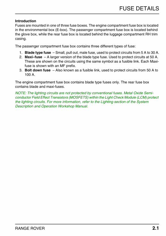
IntroductionFuses are mounted in one of three fuse boxes. The engine compartment fuse box is located in the environmental box (E-box). The passenger compartment fuse box is located behind the glove box, while the rear fuse box is located behind the luggage compartment RH trim casing.
The passenger compartment fuse box contains three different types of fuse:
1. Blade type fuse – Small, pull out, male fuse, used to protect circuits from 5 A to 30 A.2. Maxi–fuse – A larger version of the blade type fuse. Used to protect circuits at 50 A.
These are shown on the circuits using the same symbol as a fusible link. Each Maxi-fuse is shown with an MF prefix.
3. Bolt down fuse – Also known as a fusible link, used to protect circuits from 50 A to 100 A.
The engine compartment fuse box contains blade type fuses only. The rear fuse box contains blade and maxi-fuses.
NOTE: The lighting circuits are not protected by conventional fuses. Metal Oxide Semi-conductor Field Effect Transistors (MOSFETS) within the Light Check Module (LCM) protect the lighting circuits. For more information, refer to the Lighting section of the System Description and Operation Workshop Manual.
RANGE ROVER 2.1

FUSE DETAILS
ENGINE COMPARTMENT FUSE BOX
Fuse Rating Vehicle FunctionF1 30 A V8 ECM, EAT ECU.F1 30 A Td6 ECM.F2 30 A V8 Variable camshaft control solenoids.
F2 30 A Td6 CMP sensor, MAF/IAT sensor.F3 30 A V8 LH front HO2S, RH front HO2S, LH rear HO2S, RH
rear HO2S.F3 30 A Td6 EAT ECU.F4 30 A V8 ECM.
F5 30 A V8 Ignition
2.2 RANGE ROVER
FUSE DETAILS
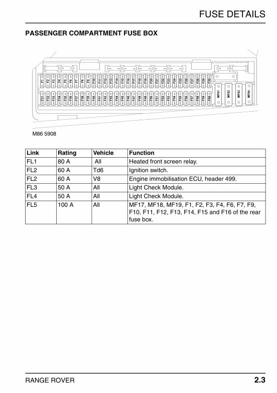
PASSENGER COMPARTMENT FUSE BOX
Link Rating Vehicle FunctionFL1 80 A All Heated front screen relay.
FL2 60 A Td6 Ignition switch.FL2 60 A V8 Engine immobilisation ECU, header 499.FL3 50 A All Light Check Module.
FL4 50 A All Light Check Module.FL5 100 A All MF17, MF18, MF19, F1, F2, F3, F4, F6, F7, F9,
F10, F11, F12, F13, F14, F15 and F16 of the rear fuse box.
F31
F1
F32
F2
F33
F3
F34
F4
F35
F5
F36
F6
F37
F7
F38
F8
F39
F9
F40
F10
F41
F11
F42
F12
F43
F13
F44
F14
F45
F15
F46
F16
F47
F17
F48
F18
F49
F19
F50
F20
F51
F21
F52
F22
F53
F23
F54
F24
F55
F25
F56
F26
F57
F27
F58
F28
F59
F60
F29
MF
61
MF
62
MF
63
MF
64
F30
M86 5908
RANGE ROVER 2.3
FUSE DETAILS
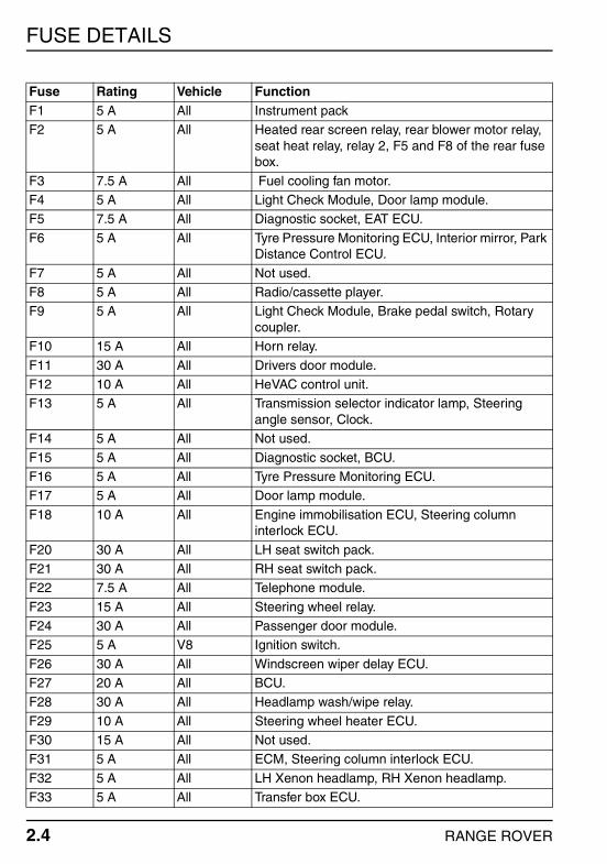
Fuse Rating Vehicle FunctionF1 5 A All Instrument packF2 5 A All Heated rear screen relay, rear blower motor relay,
seat heat relay, relay 2, F5 and F8 of the rear fuse box.
F3 7.5 A All Fuel cooling fan motor.F4 5 A All Light Check Module, Door lamp module.F5 7.5 A All Diagnostic socket, EAT ECU.
F6 5 A All Tyre Pressure Monitoring ECU, Interior mirror, Park Distance Control ECU.
F7 5 A All Not used.F8 5 A All Radio/cassette player.F9 5 A All Light Check Module, Brake pedal switch, Rotary
coupler.F10 15 A All Horn relay.
F11 30 A All Drivers door module.F12 10 A All HeVAC control unit.F13 5 A All Transmission selector indicator lamp, Steering
angle sensor, Clock.F14 5 A All Not used.
F15 5 A All Diagnostic socket, BCU.F16 5 A All Tyre Pressure Monitoring ECU.F17 5 A All Door lamp module.
F18 10 A All Engine immobilisation ECU, Steering column interlock ECU.
F20 30 A All LH seat switch pack.F21 30 A All RH seat switch pack.F22 7.5 A All Telephone module.
F23 15 A All Steering wheel relay.F24 30 A All Passenger door module.F25 5 A V8 Ignition switch.
F26 30 A All Windscreen wiper delay ECU.F27 20 A All BCU.F28 30 A All Headlamp wash/wipe relay.
F29 10 A All Steering wheel heater ECU.F30 15 A All Not used.F31 5 A All ECM, Steering column interlock ECU.
F32 5 A All LH Xenon headlamp, RH Xenon headlamp.
2.4 RANGE ROVER
F33 5 A All Transfer box ECU.

FUSE DETAILS
F34 7.5 A All HeVAC control module.F35 5 A All Centre console switch pack, Hill Descent Control
switch.F36 5 A All Not used.
F37 5 A All Transfer box ECU – Only fitted for towing purposes.
F38 5 A All Not used.F39 5 A All Steering column lighting switch.F40 5 A All CD autochanger.
F41 5 A All BCU, Rain sensor, Rear screen wiper ECU.F42 5 A All LH vanity mirror, RH vanity mirror.F43 5 A All Tilt sensor, Interior mirror, BBUS, Volumetric
sensor.F44 5 A All SRS DCU, occupancy detector, LH seat belt
buckle, RH seat belt buckle.F45 5 A All Instrument pack.
F46 5 A All Instrument pack.F47 30 A All Heated washer jet relay.F48 15 A All Not used.
F49 30 A All Radio/cassette player.F51 10 A Td6 Steering angle sensor, ABS ECU, fuel pump relay.F51 10 A V8 Steering angle sensor, Secondary Air Injection
pump relay, Secondary Air Injection pump, ABS ECU, fuel pump relay.
F52 25 A All HeVAC control module.F53 30 A All Ignition switch.
F54 15 A All EAT ECU.F55 30 A All ABS ECU.F56 7.5 A All Relay 6.
F57 15 A All Air suspension ECU.F58 20 A All Sunroof ECU.F59 20 A All Fuel burning heater, Fuel burning heater receiver.
F60 30 A All BCU.
Maxi-fuse Rating Vehicle FunctionMF61 50 A All Cooling fan control unit.
MF62 50 A V8 Secondary Air Injection pump relay.MF63 50 A All ABS ECU.MF64 50 A All Front blower motor control unit.
RANGE ROVER 2.5

FUSE DETAILS
REAR FUSE BOX
Fuse Rating Vehicle FunctionF1 20 A All Front cigar lighter, Rear cigar lighter, Front
accessory socket.
F2 25 A All Relay 4.F3 25 A All Relay 2.F4 15 A All Trailer pick-up.
F6 20 A All Trailer pick-up.F7 20 A All Rear accessory socket.F9 30 A All Heated rear window relay.
F10 20 A All Rear screen wiper motor.F11 20 A All Seat heat relay.F12 15 A All Rear blower motor relay.
F14 5 A All RF receiver.F15 25 A All Fuel pump relay.F16 10 A All Tail door relay.
Maxi-fuse
Rating Vehicle Function
MF17 50 A All Trailer ECU.MF18 50 A All Air suspension relay.
MF19 50 A All Not used.
F1
F2
F3
F4
F5
F6
F7
F8
F9
F10
F11
F12
F13
F14
F15
F16
MF
17
MF
18
MF
19
R1 R2 R3
M86 5909
2.6 RANGE ROVER

EARTH POINTS AND HEADERS
EARTH POINTS AND HEADERS
GeneralThe following illustration indicates the general position of each earth point and header on the vehicle. Refer to the Connector section for more information.
Refer to the Circuit Diagrams for details of electrical components and their associated earth points.
C0550C0018
C0706C0555
C0557C0560
C0552 C0821 C0382
C0707C0709
C0553C0360C0556
C0551C0708
C0554C0362C0017M86 5907
RANGE ROVER 3.1

EARTH POINTS AND HEADERS
3.2 RANGE ROVER
DESCRIPTION AND OPERATION
DESCRIPTION AND OPERATION
ANTI-THEFT ALARM AND CENTRAL DOOR LOCKING (CDL)
DESCRIPTIONAnti-Theft AlarmThe anti-theft alarm system fitted to New Range Rover consists three main areas:
Perimetric protection. Volumetric protection. Vehicle angle monitoring.
Perimetric ProtectionThe Body Control Unit (BCU) protects the outside of the vehicle by monitoring the condition of all four door switches, the bonnet switch, and the upper tail door switch and sounds the alarm if any are triggered.
Volumetric ProtectionThe BCU protects the inside of the vehicle via an volumetric sensor mounted in the centre of the headlining. If the volumetric sensor detects movement within the passenger compartment, it informs the BCU to sound the alarm. When the alarm is first armed, the BCU allows 15 seconds for the air within the passenger compartment to stabilise. The alarm will then become fully armed after a further 15 seconds.
Vehicle Angle MonitoringThe BCU protects against the vehicle being illegally towed away, or any of the wheels being stolen by measuring the longitudinal and transverse angle of the vehicle. The angle of the vehicle is monitored by the tilt sensor, which is located beneath the front passenger seat. When the vehicle is first armed, the tilt sensor stores the angle of the vehicle it its memory. If the angle changes more than 1.2° (longitudinal) or 1.4° (transverse), the tilt sensor informs the BCU to sound the alarm. After the alarm has been triggered once, the threshold is lowered to 1.1 ° and 1.3 ° to make the alarm even more sensitive to vehicle angle movement.
NOTE: If the upper tail door is unlocked using the RF transmitter, the tail door switch, volumetric sensor, and tilt sensor will be disabled. These will be reactivated 30 seconds after the tail door is closed and locked.
An anti-theft alarm LED is mounted in the rear view mirror to act as a visual deterrent. The flashing sequence of the LED is dependent upon the status of the anti-theft alarm system. For detailed information on the anti-theft alarm system, refer to the Anti-theft Alarm and Central Door Locking section of the Description and Operation Workshop Manual.
RANGE ROVER 4.1
DESCRIPTION AND OPERATION
Central Door Locking (CDL) and SuperlockingTwo levels of locking are available; Central Door Locking (CDL) and Superlocking. CDL locks all doors, the tail door and the fuel filler flap. Superlocking carries out the same function as CDL but also inhibits operation of the interior door handles and sill buttons.
Superlocking is activated when either the Radio Frequency (RF) handset or the key is used to lock the vehicle. CDL is activated if the CDL master switch mounted on the fascia is pressed.
The RF handset, which is incorporated into the head of the ignition key, has three buttons. Pressing the large 'Land Rover' button once locks all doors and the tail door. This is followed by a single confirmation flash of the hazard warning lamps to inform that the vehicle has been locked successfully.
Pressing and holding the 'Land Rover' button for longer than 2 seconds locks all the doors and tail door and also closes any open windows (including the sunroof). Completion of this is again followed by a single confirmation flash of the hazard warning lamps to inform that the vehicle has been locked successfully.
Pressing the unlock 'Arrow' button once unlocks the drivers door. Pressing the unlock 'Arrow' button a second time unlocks the remaining three doors and the tail door. Pressing and holding the 'Arrow' button for longer than 2 seconds opens all the windows and the sunroof.
NOTE: Automatic opening and closing of the windows and sunroof is suspended if the lock or unlock button is released before the operation has been completed.
A third button on the handset operates the upper tail door lock. A single press of this button will unlock the upper tail door and temporarily suspend operation of the anti-theft alarm system. Once the tail door has been closed the tail door is automatically locked and the anti-theft alarm system reinstated. This is confirmed by a single flash of the hazard warning lamps.
For a detailed description of the CDL system, refer to the Anti-theft Alarm and Central Door Locking section of the Description and Operation Workshop Manual.
4.2 RANGE ROVER

DESCRIPTION AND OPERATION
OPERATIONAnti-Theft AlarmPower DistributionFeed from the positive battery terminal (C0192) is supplied to fusible link 1, fuse 15, fuse 43, and fuse 53 (C0632) on an R wire. All are located in the passenger compartment fuse box. Fuse 15 (C0586) provides a constant battery feed to the Body Control Unit (BCU) (C0660) on an RS wire. The BCU (C0660) is earthed on an NB wire.
Fusible link 1 (C0588) provides a constant battery feed to fuse 14 of the rear fuse box (C2024) on an R wire. Fuse 14 (C2022) provides a constant battery feed to the radio frequency (RF) receiver (C0674) on an RB wire.
Fuse 43 of the passenger compartment fuse box (C0586) provides a constant battery feed to the following:
The Battery Backed-Up Sounder (BBUS) (C0666) on an RN wire. The volumetric sensor (C0359) on an RW wire. The tilt sensor (C0960) on an RB wire.
Fuse 53 of the passenger compartment fuse box (C0583) provides a constant battery feed to the ignition switch (C0099 on Td6 vehicles, C0028 on V8 vehicles) on an R wire. When the ignition switch is turned to the 'ignition' position, current flows across the switch (C0099 on Td6 vehicles, C0028 on V8 vehicles) to fuse 6 of the passenger compartment fuse box (C0585) on a G wire. Fuse 6 (C0587) provides an ignition feed to the interior mirror (C0698) on a GW wire.
RF ReceiverThe RF receiver (C0674) is located at the top of the upper tail door, and is provided a constant battery feed from fuse 14 of the rear fuse box (C2022) on an RB wire. The RF receiver is connected to an element in the rear screen via a pair of B wires. The RF receiver uses the rear screen element as an aerial.
NOTE: The B wires connecting the RF receiver to the rear screen element are not shown on the system circuit diagrams as they are fly leads incorporated into the manufacture of the rear screen.
The RF receiver converts high frequency wave forms transmitted by the remote handset into bi-phase, pulsed signals that can be understood by the BCU. The RF receiver (C0674) is connected to the BCU (C0660) by a WY wire.
RANGE ROVER 4.3

DESCRIPTION AND OPERATION
Volumetric SensorThe volumetric sensor monitors the inside of the vehicle by emitting a series of ultrasound pulses, and measuring the profile of the returned echo. The sensor (C0359) is located the centre of the headlining, and is provided a constant battery feed from fuse 43 of the passenger compartment fuse box (C0586) on an RW wire.
When the anti-theft alarm is armed, the BCU (C0661) 'switches on' the volumetric sensor by providing a pulsed voltage signal to the tilt sensor (C0960) on a BS wire. This signal is relayed to the volumetric sensor (C0359) on a BW wire. If the volumetric sensor detects movement within the passenger compartment, it provides a feed to the BCU (C0661) on a BY wire. The volumetric sensor (C0359) is earthed on an N wire.
Tilt SensorThe tilt sensor monitors the angle of the vehicle. If the angle of the vehicle moves more than the thresholds outlined in the Description section, the alarm will be triggered. The sensor (C0960) is located beneath the front passenger seat, and is provided a constant battery feed from fuse 43 of the passenger compartment fuse box (C0586) on an RW wire. When the anti-theft alarm is armed, the BCU (C0661) 'switches on' the tilt sensor (C0960) by providing a pulsed voltage signal on a BS wire.
When the anti-theft alarm system is activated, the tilt sensor (C0960) provides a voltage pulse to the BCU (C0661) on a BU wire. If this isn't received within a set time, the BCU determines that the unit is defective.
If the tilt sensor is triggered, it provides a voltage pulse to the BCU (C0661) on a BU wire. Recognising this signal, the BCU (C0661) returns a pulsed voltage signal to the tilt sensor (C0960) on a BS wire.
4.4 RANGE ROVER
DESCRIPTION AND OPERATION
Battery Backed-Up Sounder (BBUS)The BBUS (C0666) is mounted adjacent the brake servo, and is provided a constant battery feed by fuse 43 of the passenger compartment fuse box (C0586) on an RN wire. Dependant upon market configuration, the BBUS can emit one of three tones:
Continuous. Pulsed. Modulated.
When the anti-theft alarm is armed, the BCU (C0661) 'switches on' the BBUS by providing a pulsed voltage signal to the tilt sensor (C0960) on a BS wire. This signal is relayed to the BBUS (C0666) on a BG wire.
When the alarm is triggered, the BBUS (C0662) provides a feed to the BBUS (C0666) on a BU wire. The BBUS (C0666) is earthed on an N wire.
Perimetric ProtectionThe BCU (C0660) is located beneath the front passenger seat, and is provided a constant battery feed from fuse 15 of the passenger compartment fuse box (C0586) on an RS wire. The door, bonnet, and tail door switches are all normally open switches. When any of these panels are opened, the switch contacts close and an earth path is created. The BCU (C0660) monitors the condition of door bonnet and tail door switches as follows:
The BCU monitors the condition of the drivers door switch (C1449) via the drivers door module (C2058) on a UR then NW wire. The drivers door switch (C1449) is earthed on an N wire.
The BCU monitors the condition of the front passenger door switch (C1451) via the passenger door module (C2057) on a UR then NW wire. The passenger door switch (C1451) is earthed on an N wire.
The BCU monitors the condition of the LH rear passenger door (C0442) on an NS then NG wire. The LH rear passenger door switch (C0442) is earthed on an N wire.
The BCU monitors the condition of the RH rear passenger door (C0442) on an NW then NG wire. The RH rear passenger door switch (C0442) is earthed on an N wire.
The BCU monitors the condition of the bonnet switch (C0007) on a PG wire. The bonnet switch (C0007) is earthed on an N wire.
The BCU monitors the condition of the upper tail door switch (C0383) on an SW wire. The upper tail door switch (C0383) is earthed on an N wire.
NOTE: The LH rear and RH rear passenger door switches have the same connector number as they utilise the same harness.
Anti-theft Alarm LEDThe anti-theft alarm LED is located in the rear view mirror. The flashing sequence of the LED (C0698) is controlled by the BCU (C0661) on an SBY wire.
RANGE ROVER 4.5

DESCRIPTION AND OPERATION
Central Door Locking (CDL)Power DistributionFeed from the positive battery terminal (C0192) is supplied to the following on an R wire:
Fusible link 1. Fuse 11. Fuse 15. Fuse 24. Fuse 60.
All are located in the passenger compartment fuse box (C0632). Fuse 15 (C0586) provides a constant battery feed to the BCU (C0660) on an RS wire. Fuse 60 (C0582) also provides a feed to the BCU (C0662) on an RW wire. The BCU (C0660) is earthed on an NB wire.
Fuse 24 (C0583) provides a constant battery feed to the passenger door module (C2016) on an RW wire. Fuse 11 (C0585) provides a constant battery feed to the drivers door module (C2017) on an RP wire.
Fusible link 1 (C0588) is connected to fuse 14 and fuse 16 of the rear fuse box (C2024) on an R wire. Fuse 14 (C2022) provides a constant battery feed to the RF receiver (C0674) on an RB wire. Fuse 16 provides a constant battery feed to relay 8, which is also located in the rear fuse box.
RF ReceiverThe RF receiver (C0674) is located at the top of the upper tail door and is provided a constant battery feed from fuse 14 of the rear fuse box (C2022) on an RB wire. The RF receiver converts the radio frequency signals from the remote handset and converts them into a digital signals. The RF receiver (C0674) provides the digital signal to the BCU (C0660) on a WY wire. The BCU processes the signal from the RF receiver and carries out the appropriate function.
CDL Master SwitchThe non-latching CDL master switch is mounted on the fascia, below the hazard warning switch. The BCU (C0661) monitors the condition of the switch (C0700) by providing a feed on an SN wire. When the switch is pressed, the switch contacts close and a momentary earth is created on an N wire. When the BCU registers this earth, it will lock all four doors, the tail door, and the fuel filler flap. Pressing the button a second time unlocks all four doors, the tail door and the fuel filler flap.
NOTE: Superlocking is not initiated when the CDL master switch is pressed.
4.6 RANGE ROVER
DESCRIPTION AND OPERATION
Drivers DoorThe BCU controls operation of the drivers door lock via the drivers door module. The drivers door module (C2017) is provided a constant battery feed from fuse 11 of the passenger compartment fuse box (C0585) on an RP wire. The module (C2017) is earthed on an N wire.
The BCU (C0660) communicates with the drivers door module (C2058) via the P-bus on a UR wire. If the drivers door module (C2058) receives an unlock signal from the BCU, it provides a feed to the door lock motor (C1449) on a U wire. Current flows across the motor (C1449) and is provided an earth path via the drivers door module (C2058) on a B wire.
The drivers door can also be unlocked using the key. The drivers door module (C2058) monitors the condition of the door lock barrel switch (C1449) on a WB wire. When the door lock is moved to the unlock position, the switch contacts close and an earth path is created on an N wire. Sensing this, the drivers door module unlocks the drivers door.
If the drivers door module (C2058) receives a lock signal from the BCU, it provides a feed to the door lock motor (C1449) on a B wire. Current flows across the motor (C1449) and is provided an earth path via the drivers door module (C2058) on a U wire.
If the drivers door module (C2058) receives a superlock signal from the BCU, it provides a feed to the superlock motor (C1449) on a W wire. Current flows across the superlock motor (C1449) and is provided an earth path via the drivers door module (C2058) on a U wire.
The drivers door can also be locked using the key. The drivers door module (C2058) monitors the condition of the door lock barrel switch (C1449) on a UR wire. When the door lock is moved to the lock position, the switch contacts close and an earth path is created on an N wire. Sensing this, the drivers door module locks the drivers door.
Front Passenger DoorThe BCU controls operation of the front passenger door lock via the passenger door module. The passenger door module (C2016) is provided a constant battery feed from fuse 24 of the passenger compartment fuse box (C0583) on an RW wire. The module (C2016) is earthed on an N wire.
The BCU (C0660) communicates with the passenger door module (C2057) via the P-bus on a UR wire. If the passenger door module (C2057) receives an unlock signal from the BCU, it provides a feed to the door lock motor (C1451) on a U wire. Current flows across the motor (C1451) and is provided an earth path via the drivers door module (C2057) on a B wire.
If the passenger door module (C2057) receives a lock signal from the BCU, it provides a feed to the door lock motor (C1451) on a B wire. Current flows across the motor (C1451) and is provided an earth path via the passenger door module (C2057) on a U wire.
If the passenger door module (C2057) receives a superlock signal from the BCU, it provides a feed to the superlock motor (C1451) on a W wire. Current flows across the superlock motor (C1451) and is provided an earth path via the drivers door module (C2057) on a U wire.
RANGE ROVER 4.7

DESCRIPTION AND OPERATION
Rear Passenger DoorsWhen the BCU (C0662) receives an unlock signal from the RF receiver, it provides a feed to the RH and LH rear (C0442) door lock motors on a pair of U wires. Current flows across the motors (C0442) to earth path via the BCU (C0662) on a pair of B wires.
When the BCU (C0662) receives a lock signal from the RF receiver, it provides a feed to the RH and LH rear door lock motors (C0442) on a pair of B wires. Current flows across the motors (C0442) to earth via the BCU (C0662) on a pair of U wires.
When the BCU (C0662) receives a superlock signal from the RF receiver, it provides a feed to the RH and LH rear (C0442) superlock motors on a pair of W wires. Current flows across the superlock motors (C0442) to earth via the BCU (C0662) on a pair of U wires.
Tail DoorThe non-latching tail door switch is located on the centre console, adjacent to the clock. When the switch is pressed a momentary earth path is created. Sensing this, the BCU (C0662) provides a feed to the upper tail door motor (C0383) on a YN wire. The motor (C0383) is earthed on an N wire.
Once the upper tail door has been opened, the lower tail door can be opened. This can be carried out by pressing the non-latching switch located on the upper edge of the lower tail door.
The BCU (C0660) monitors the condition of the switch (C0615) by providing a feed on a YB wire. When pressed, the switch contacts close and a momentary earth path is created via the rear fuse box. Sensing this, the BCU (C0661) provides a feed to relay 8 of the rear fuse box (C2022) on an NY wire. This feed energises relay 8.
The energised relay 8 (C2022) allows a feed from fuse 16 of the rear fuse box to power the RH lower (C2052) and LH lower (C0617) tail door motors on UW wires. Both motors are earthed on N wires.
Fuel Filler FlapWhen the BCU (C0662) receives an unlock signal from the RF receiver, it provides a feed to the fuel filler flap release motor (C0690) on a U wire. On European vehicles, current flows across the motor (C0690) and is provided an earth path via the BCU (C0662) on a W wire. On NAS vehicles, current flows across the motor (C0690) and is provided an earth path via the BCU (C0662) on a B wire.
When the BCU (C0662) receives a lock signal from the RF receiver, it provides a feed to the fuel filler flap release motor (C0690) on a W wire (B wire on NAS vehicles). Current flows across the motor (C0690) and is provided an earth path via the BCU (C0662) on a U wire.
4.8 RANGE ROVER

DESCRIPTION AND OPERATION
ENGINE IMMOBILISATION
DESCRIPTIONGeneralThe function of the engine immobilisation system is to prevent unauthorised starting of the vehicle. The system is controlled by an immobilisation ECU which is located beneath the centre console, adjacent to the handbrake. Re-mobilisation is achieved via a transponder in the vehicle key, which is read by a transponder coil when the ignition switch is turned to the 'auxiliary' position. The transponder coil is mounted around the ignition switch.
For a detailed description of the engine immobilisation system, refer to the Security section of the Description and Operation Workshop Manual.
OPERATIONTd6Power DistributionFeed from the positive battery terminal (C0192) is supplied to fusible link 2, fuse 18, and fuse 53 of the passenger compartment fuse box (C0632) on an R wire. Fuse 18 (C0584) provides a constant battery feed to the immobilisation ECU (C0059) and the steering column interlock ECU (C2055) on a pair of RY wires.
Fuse 53 (C0583) provides a constant battery feed to the ignition switch (C0099) on an R wire. When the ignition switch is turned to the 'auxiliary' position, current flows across the switch (C0099) to fuse 39 of the passenger compartment fuse box (C0585) on a PB wire. Fuse 39 (C0587) provides an auxiliary ignition feed to the immobilisation ECU (C0059) and the steering column interlock ECU (C2055) on a pair of PB wires.
When the ignition switch is turned to the 'ignition' position, current flows across the switch (C0099) to fuse 31 of the passenger compartment fuse box (C0585) on a G wire. Fuse 31 (C0587) provides an ignition feed to the steering column interlock ECU (C2055) on a GB wire.
Fusible link 2 of the passenger compartment fuse box (C0591) provides a constant battery feed to the ignition switch (C0099) on an R wire. When the ignition switch is turned to the 'crank' position, current flows across the switch (C0099) to the immobilisation ECU (C0059) on a BY wire.
RANGE ROVER 4.9

DESCRIPTION AND OPERATION
Steering Column Interlock ECUThe steering column interlock ECU (C2055) receives the following power supplies:
A constant battery feed from fuse 18 of the passenger compartment fuse box (C0584) on an RY wire.
An auxiliary ignition feed from fuse 39 of the passenger compartment fuse box (C0587) on a PB wire.
An 'ignition on' feed from fuse 31 of the passenger compartment fuse box (C0587) on a GB wire.
The ECU is earthed on an NB wire.
Transponder CoilThe transponder coil (C0049) is connected to the immobilisation ECU (C0059) by YU and YN wires. Both connections between the immobilisation ECU and the transponder coil switch between being both inputs and outputs. The transponder coil reads the vehicle identification information contained within the key transponder and relays it to the immobilisation ECU.
Immobilisation ECUThe immobilisation ECU (C0059) is located beneath the centre console, adjacent to the handbrake. It receives a constant battery feed from fuse 18 of the passenger compartment fuse box (C0584) on an RY wire, and an auxiliary ignition feed from fuse 39 of the passenger compartment fuse box (C0587) on a PB wire.
If the immobilisation ECU (C0059) has received a valid signal from both the transponder coil (C0049) and the steering column interlock ECU (C2055) when the ignition switch is turned to the 'crank' position, it transmits a rolling code to the Engine Control Module (ECM) (C0331) on a BP wire. The immobilisation ECU (C0059) also provides a feed to the starter motor relay (C0179) on a B wire.
For more information on operation of the starter motor, refer to the Starting and Charging – Td6 section of this manual. + STARTING AND CHARGING – Td6.
4.10 RANGE ROVER
DESCRIPTION AND OPERATION
V8Power DistributionFeed from the positive battery terminal (C0192) is supplied to the following on an R wire:
Fusible link 2. Fuse 18. Fuse 25. Fuse 53.
All are located in the passenger compartment fuse box (C0632).
Fusible link 2 (C0591) provides a constant battery feed to the immobilisation ECU (C0059) on an R wire. Fuse 18 (C0584) provides a constant battery feed to the immobilisation ECU (C0059) and the steering column interlock ECU (C2055) on a pair of RY wires.
Fuse 53 (C0583) provides a constant battery feed to the ignition switch (C0028) on an R wire. When the ignition switch is turned to the 'auxiliary' position, current flows across the switch (C0028) to fuse 39 of the passenger compartment fuse box (C0585) on a PB wire. Fuse 39 (C0587) provides an auxiliary ignition feed to the immobilisation ECU (C0059) and the steering column interlock ECU (C2055) on a pair of PB wires.
When the ignition switch is turned to the 'ignition' position, current flows across the switch (C0028) to fuse 31 of the passenger compartment fuse box (C0585) on a G wire. Fuse 31 (C0587) provides an ignition feed to the steering column interlock ECU (C2055) on a GB wire.
Fuse 25 of the passenger compartment fuse box (C0583) provides a constant battery feed to the ignition switch (C0028) on an RU wire. When the ignition switch is turned to the 'crank' position, current flows across the switch (C0028) to the Engine Control Module (ECM) (C0331) on a BY wire.
Steering Column Interlock ECUThe steering column interlock ECU (C2055) receives the following power supplies:
A constant battery feed from fuse 18 of the passenger compartment fuse box (C0584) on an RY wire.
An auxiliary ignition feed from fuse 39 of the passenger compartment fuse box (C0587) on a PB wire.
An 'ignition on' feed from fuse 31 of the passenger compartment fuse box (C0587) on a GB wire.
The ECU is earthed on an NB wire.
RANGE ROVER 4.11
DESCRIPTION AND OPERATION
Transponder CoilThe transponder coil (C0049) is connected to the immobilisation ECU (C0059) by YU and YN wires. Both connections between the immobilisation ECU and the transponder coil switch between being both inputs and outputs. The transponder coil reads the vehicle identification information contained within the key transponder and relays it to the immobilisation ECU.
Immobilisation ECUThe immobilisation ECU (C0059) is located beneath the centre console, adjacent to the handbrake. It receives a constant battery feed from fuse 18 of the passenger compartment fuse box (C0584) on an RY wire, and an auxiliary ignition feed from fuse 39 of the passenger compartment fuse box (C0587) on a PB wire.
If the immobilisation ECU (C0059) has received a valid signal from both the transponder coil (C0049) and the steering column interlock ECU (C2055) when the ignition switch is turned to the crank position, it transmits a rolling code to the Engine Control Module (ECM) (C0331) on a BP wire.
The immobilisation ECU (C0059) also provides a feed to the interlock relay (C1455) on a B wire. The energised interlock relay (C1455) provides a feed to the starter motor relay (C0179) on a B then BY wire.
For more information on operation of the starter motor, refer to the Starting and Charging – V8 section of this manual. + STARTING AND CHARGING – V8.
4.12 RANGE ROVER
DESCRIPTION AND OPERATION
WINDOWS
DESCRIPTIONGeneralOperation of all four windows is controlled by the Body Control Unit (BCU) via the P-bus. The P-bus allows communication between the BCU and the drivers and passenger door modules. The door modules are mounted in the relevant front door. The drivers door module features four rocker switches, and a non-latching switch to inhibit operation of the rear windows. A rocker switch is also located on the front passenger door, and both rear passenger doors for operation of the relevant window.
Both front and rear windows feature an anti-trap function. If an obstacle is detected while the window is being closed, it will return to the fully open position.
For a detailed description of window lift operation, refer to the Windows section of the Description and Operation Workshop Manual.
For a detailed description of the P-bus, refer to the Communication Databuses section of the Description and Operation Workshop Manual.
OPERATIONFrontPower DistributionFeed from the positive battery terminal (C0192) is supplied to fuse 11, fuse 24, and fuse 53 of the passenger compartment fuse box (C0632) on an R wire. Fuse 11 (C0585) provides a constant battery feed to the drivers door module (C2017) on an RP wire. Fuse 24 (C0583) provides a constant battery feed to the passenger door module (C2016) on an RW wire.
Fuse 53 (C0583) provides a constant battery feed to the ignition switch (C0099 on Td6 vehicles, C0028 on V8 vehicles) on an R wire. When the ignition switch is turned to the 'auxiliary' position, current flows across the switch (C0099 on Td6 vehicles, C0028 on V8 vehicles) to fuse 41 of the passenger compartment fuse box (C0585) on a PB wire. Fuse 41 (C0586) provides an auxiliary ignition feed to the Body Control Unit (BCU) (C0660) on a PW wire. The BCU (C0662) is earthed on an N wire.
Drivers WindowWhen the drivers door switch is moved to the 'Up' position, the feed from fuse 11 of the passenger compartment fuse box (C0585) flows through the drivers door module (C2017) to earth on an N wire. The drivers door module (C2017) will now provide a feed to the window lift motor (C0740) on a BS wire. Current flows across the motor and back to the drivers door module (C2017) on a BG wire. The drivers door module provides an earth path for the motor on an N wire. When the current draw of the window lift motor increases, the BCU (via the P-bus) determines the window has reached the limit of its travel and cuts the supply from the drivers door module.
RANGE ROVER 4.13

DESCRIPTION AND OPERATION
When the drivers door switch is moved to the 'Down' position, the feed from fuse 11 of the front passenger compartment fuse box (C0585) flows through the drivers door module (C2017) to earth on an N wire. The drivers door module (C2017) will now provide a feed to the window lift motor (C0740) on a BG wire. Current flows across the motor and back to the drivers door module (C2017) on a BS wire. The drivers door module provides an earth path for the motor on an N wire. When the current draw of the window lift motor increases, the BCU (via the P-bus) determines the window has reached the limit of its travel and cuts the supply from the drivers door module.
Front Passenger WindowWhen the passenger door switch is moved to the 'Up' position, the feed from fuse 24 of the passenger compartment fuse box (C0583) flows through the passenger door module (C2016) to earth on an N wire. The passenger door module (C2016) will now provide a feed to the window lift motor (C0741) on a BS wire. Current flows across the motor and back to the passenger door module (C2016) on a BG wire. The passenger door module provides an earth path for the motor on an N wire. When the current draw of the window lift motor increases, the BCU (via the P-bus) determines the window has reached the limit of its travel and cuts the supply from the passenger door module.
When the passenger door switch is moved to the 'Down' position, the feed from fuse 24 of the front passenger compartment fuse box (C0583) flows through the passenger door module (C2016) to earth on an N wire. The passenger door module (C2016) will now provide a feed to the window lift motor (C0741) on a BG wire. Current flows across the motor and back to the passenger door module (C2016) on a BS wire. The passenger door module provides an earth path for the motor on an N wire. When the current draw of the window lift motor increases, the BCU (via the P-bus) determines the window has reached the limit of its travel and cuts the supply from the passenger door module.
Anti-TrapThe anti-trap system consists of an anti-trap seal, which runs along the door glass frame. The seal contains two elements, with a combined resistance of 1.2 kΩ. This resistance is constantly monitored by the BCU via the P-bus. If the window meets an obstacle, it pushes it against the anti-trap seal. This 'shorts' the two elements together, reducing the seals resistance to approximately 500 Ω. When the BCU detects this drop in resistance, it reverses the feed to the window lift motor. Both the drivers door module (C2058) and the passenger door module (C2057) are connected to the anti-trap seals (C0599 & C0600 respectively) by NR wires. The anti-trap seals are both earthed on N wires.
4.14 RANGE ROVER

DESCRIPTION AND OPERATION
RearPower DistributionFeed from the positive battery terminal (C0192) is supplied to fuse 53 and fuse 60 of the passenger compartment fuse box (C0632) on an R wire. Fuse 60 (C0582) provides a constant battery feed to the BCU (C0662) on an RW wire.
Fuse 53 (C0583) provides a constant battery feed to the ignition switch (C0099 on Td6 vehicles, C0028 on V8 vehicles) on an R wire. When the ignition switch is turned to the 'auxiliary' position, current flows across the switch (C0099 on Td6 vehicles, C0028 on V8 vehicles) to fuse 41 of the passenger compartment fuse box (C0585) on a PB wire. Fuse 41 (C0586) provides an auxiliary ignition feed to the BCU (C0660) on a PW wire.
RH Rear WindowThe BCU (C0660) provides a feed to the RH rear window switch (C0732) on SY then N and SU then SB wires. If the switch is moved to the 'Up' position, the switch contacts close momentarily, allowing the feed on the SY then N wire to flow to earth on an N wire. Sensing this earth path, the BCU (C0662) provides a feed to the RH rear window lift motor (C0304) on a BN then BG wire. Current flows across the motor (C0304) and back to the BCU (C0662) on a US then UP wire. When the current draw of the window lift motor increases, the BCU determines the window has reached the limit of its travel and cuts the supply to the motor.
If the switch is moved to the 'Down' position, the switch contacts close momentarily, allowing the feed on the SU then SB wire to flow to earth on an N wire. Sensing this earth path, the BCU (C0662) provides a feed to the RH rear window lift motor (C0304) on a UP then US wire. Current flows across the motor (C0304) and back to the BCU (C0662) on a BG then BN wire. When the current draw of the window lift motor increases, the BCU determines the window has reached the limit of its travel and cuts the supply to the motor.
LH Rear WindowThe BCU (C0660) provides a feed to the LH rear window switch (C0732) on SN and SB wires. If the switch is moved to the 'Up' position, the switch contacts close momentarily, allowing the feed on the SN wire to flow to earth on an N wire. Sensing this earth path, the BCU (C0662) provides a feed to the LH rear window lift motor (C0304) on a BG wire. Current flows across the motor (C0304) and back to the BCU (C0662) on a US wire. When the current draw of the window lift motor increases, the BCU determines the window has reached the limit of its travel and cuts the supply to the motor.
If the switch is moved to the 'Down' position, the switch contacts close momentarily, allowing the feed on the SB wire to flow to earth on an N wire. Sensing this earth path, the BCU (C0662) provides a feed to the LH rear window lift motor (C0304) on a US wire. Current flows across the motor (C0304) and back to the BCU (C0662) on a BG wire. When the current draw of the window lift motor increases, the BCU determines the window has reached the limit of its travel and cuts the supply to the motor.
RANGE ROVER 4.15
DESCRIPTION AND OPERATION
Anti-TrapThe anti-trap system consists of an anti-trap seal, which runs along the door glass frame. The seal contains two elements, with a combined resistance of 1.2 k. This resistance is constantly monitored by the BCU. If the window meets an obstacle, it pushes it against the anti-trap seal. This 'shorts' the two elements together, reducing the seals resistance to approximately 500 . When the BCU detects this drop in resistance, it reverses the feed to the window lift motor.
The BCU (C0661) is connected to the RH rear anti-trap seal (C2015) by an NR then NY wire, and to the LH rear anti-trap seal (C2015) by an NY wire. Both anti-trap seals (C2015) are earthed on N wires.
NOTE: Both rear anti-trap seals have the same connector number as they utilise the same harness.
4.16 RANGE ROVER

DESCRIPTION AND OPERATION
SUNROOF
DESCRIPTIONGeneralOperation of the sunroof is controlled via the three position switch located on the front of the headlining. Moving the switch rearwards opens the sunroof. Similarly, moving the switch forward closes the sunroof. A single press in the centre of the switch opens or closes the sunroof from the tilt position.
All switch inputs are registered by the sunroof ECU, which is located behind the front of the headlining, adjacent the sunroof motor. The sunroof ECU also receives messages from the Body Control Unit (BCU) via the P-Bus to enable it to carry out its automatic closing and opening routine. Automatic closing is carried out when the 'Land Rover' button on the remote handset is pressed and held for longer than 2 seconds. Similarly, pressing and holding the 'Arrow' key on the remote handset for longer than 2 seconds opens both the sunroof and all windows.
For more information on P-Bus messages, refer to the Communication Databuses section of the System Description and Operation Workshop Manual.
For more information on Sunroof operation, refer to the Sunroof section of the System Description and Operation Workshop Manual.
For more information on automatic opening and closing, refer to the Anti-theft Alarm and Central Door Locking section of this manual. + ANTI-THEFT ALARM AND CENTRAL DOOR LOCKING (CDL).
OPERATIONPower DistributionFeed from the positive battery terminal (C0192) is supplied to fuse 53, and fuse 58 of the passenger compartment fuse box (C0632) on an R wire. Fuse 58 (C0582) provides a constant battery feed to the sunroof ECU (C0784) on an RS wire. Fuse 53 (C0583) provides a constant battery feed to the ignition switch (C0099 on Td6 vehicles, C0028 on V8 vehicles) on an R wire. When the ignition switch is turned to the 'auxiliary' position, current flows across the switch (C0099 on Td6 vehicles, C0028 on V8 vehicles) to fuse 41 of the passenger compartment fuse box (C0585) on a PB wire. Fuse 41 (C0586) provides an auxiliary ignition feed to the Body Control Unit (BCU) (C0660) on a PW wire.
RANGE ROVER 4.17

DESCRIPTION AND OPERATION
Sunroof ECUThe sunroof ECU (C0784) provides a feed to the sunroof switch (C0363) on a YS wire. If the switch is moved to the 'Open' position, a feed is returned to the ECU (C0784) on a YG wire. The ECU will now power the sunroof motor to open the sunroof. By measuring the voltage pulses returned from two Hall effect sensors located within the sunroof mechanism, the ECU can determine when the sunroof has reached the end of its travel and cut the voltage supply to the motor.
If the switch is moved to the 'Close' position, a feed is returned to the sunroof ECU (C0784) on an SB wire. The ECU will now power the sunroof motor to close the sunroof. By measuring the voltage pulses returned from the two Hall effect sensors, the ECU determines when the sunroof has reached the end of its travel and cuts the voltage supply to the motor.
If the centre of the switch is pressed, a feed is returned to the sunroof ECU (C0784) on a YW wire. The ECU will now power the sunroof motor in the 'Close' direction to raise the rear of the sunroof. By measuring the voltage pulses returned from the two Hall effect sensors, the ECU determines when the sunroof has reached the end of its travel and cuts the voltage supply to the motor.
If the centre of the switch is pressed a second time, a feed is returned to the sunroof ECU (C0784) on a YW wire. The ECU will now power the sunroof motor in the 'Open' direction to lower the sunroof. By measuring the voltage pulses returned from the two Hall effect sensors, the ECU determines when the sunroof has reached the end of its travel and cuts the voltage supply to the motor.
The sunroof ECU (C0784) is earthed on an N wire.
Body Control Unit (BCU)The Body Control Unit (BCU) (C0660) communicates with the sunroof ECU (C0784) via the P-Bus. In addition to enabling automatic opening and closing to be carried out, the BCU also triggers the sunroof ECU into an energy saving 'sleep' mode.
For a detailed description of P-Bus operation and messages, refer to the Communication Databuses section of the System Description Operation Workshop Manual.
4.18 RANGE ROVER
DESCRIPTION AND OPERATION
DOOR MIRRORS
DESCRIPTIONGeneralThe door mirrors operate when the ignition switch is turned to the 'auxiliary' position. Operation of the door mirrors is carried out by door modules located in each front door, in conjunction with the Body Control Unit (BCU).
The BCU can store up to three mirror positions in its memory, which it transmits to the door modules via the peripheral (P) bus. The BCU also initiates mirror heating if the outside temperature is between -10 °C and 35 °C.
If reverse gear is selected, the passenger door mirror will automatically lower to enable the driver to gain a better view of the kerb. When reverse gear is deselected, the mirror returns to its original position.
For a detailed description of door mirror operation, refer to the Exterior Fittings – Door Mirrors section of the Description and Operation Workshop Manual.
OPERATIONPower DistributionFeed from the positive battery terminal (C0192) is supplied to fuse 11, fuse 24, and fuse 53 of the passenger compartment fuse box (C0632) on an R wire. Fuse 11 (C0585) provides a constant battery feed to the drivers door module (C2017) on an RP wire. Fuse 24 (C0583) provides a constant battery feed to the passenger door module (C2016) on an RW wire. The drivers (C2017) and passenger (C2016) door modules are both earthed on N wires.
Fuse 53 (C0583) provides a constant battery feed to the ignition switch (C0099 on Td6 vehicles, C0028 on V8 vehicles) on an R wire. When the ignition switch is turned to the 'auxiliary' position, current flows across the switch (C0099 on Td6 vehicles, C0028 on V8 vehicles) to fuse 41 of the passenger compartment fuse box (C0585) on a PB wire. Fuse 41 (C0586) provides an auxiliary ignition feed to the Body Control Unit (BCU) (C0660) on a PW wire. The BCU (C0662) is earthed on an N wire.
RANGE ROVER 4.19
DESCRIPTION AND OPERATION
Drivers Door MirrorHorizontal AdjustmentWhen RH adjustment of the drivers door mirror is required, the drivers door module (C2271) provides a feed to the horizontal motor on a G wire. Current flows across the motor and back to the drivers door module (C2271) on an R wire. If LH adjustment of the drivers door mirror is required, the feed to the horizontal motor is reversed. The motor is provided a feed on an R wire, with an earth path provided by the drivers door module (C2271) via a G wire.
To prevent the vertical motor from operating, the drivers door module (C2271) also provides a feed to the vertical motor on an S wire. As the potential difference across the motor is 0V, the motor does not operate.
Vertical AdjustmentWhen upwards adjustment of the drivers door mirror is required, the drivers door module (C2271) provides a feed to the vertical motor on an S wire. Current flows across the motor and back to the drivers door module (C2271) on an R wire. If downwards adjustment of the drivers door mirror is required, the feed to the vertical motor is reversed. The motor is provided a feed on an R wire, with an earth path provided by the drivers door module (C2271) via an S wire.
To prevent the horizontal motor from operating, the drivers door module (C2271) also provides a feed to the horizontal motor on a G wire. As the potential difference across the motor is 0V, the motor does not operate.
Mirror MemoryThe door mirror memory function works in conjunction with the seat and steering wheel memory functions. The BCU (C0660) receives a memory request from the seat memory ECU (C0862) via the K-bus on a WRY wire. The BCU (C0660) relays this message to the drivers door module (C2058) via the P-bus on a UR wire.
When the drivers door module receives a memory request it moves the mirrors as described above. Two potentiometers are fitted within the mirror assembly to determine its position. The drivers door module (C2271) provides a feed to both potentiometers on an O wire. The horizontal potentiometer is provided an earth path by the drivers door module (C2271) on a B wire. By measuring the current returned on a W wire, the drivers door module can determine the mirror's horizontal position.
The vertical potentiometer is also provided an earth path by the drivers door module (C2271) on a B wire. By measuring the current returned on a K wire, the drivers door module can determine the mirror's vertical position.
4.20 RANGE ROVER

DESCRIPTION AND OPERATION
Mirror FoldA non-latching mirror folding switch is located on the drivers door module. When the switch is pressed a first time, the drivers door module (C2271) provides a feed to the mirror fold motor on an RU wire. Current flows across the motor and back to the drivers door module (C2271) on a GN wire. The drivers door mirror now moves to the folded position. If the switch is pressed a second time, the feed to the fold motor is reversed. The motor is provided a feed on a GN wire, with an earth path provided by the drivers door module (C2271) via an RU wire.
NOTE: Mirror fold is disabled if vehicle speed is greater than 10 km/h (6 mph).
The drivers door module (C2058) communicates the mirror fold request to the passenger door module (C2057) via the P-bus on a UR wire.
Mirror HeaterIf the BCU (C0660) receives an outside temperature reading of between -10 °C and 35 °C, it informs the drivers door module (C2058) to initiate mirror heating via the P-bus on a UR wire. Pin 7 of the drivers door module (C2271) provides a feed to the door mirror heater on a B wire. An earth path is provided via pin 6 of the drivers door module (C2271), also on a B wire.
Passenger Door MirrorHorizontal AdjustmentWhen RH adjustment of the passenger door mirror is required, the passenger door module (C2271) provides a feed to the horizontal motor on a G wire. Current flows across the motor and back to the passenger door module (C2271) on an R wire. If LH adjustment of the passenger door mirror is required, the feed to the horizontal motor is reversed. The motor is provided a feed on an R wire, with an earth path provided by the passenger door module (C2271) via a G wire.
To prevent the vertical motor from operating, the passenger door module (C2271) also provides a feed to the vertical motor on an S wire. As the potential difference across the motor is 0V, the motor does not operate.
Vertical AdjustmentWhen upwards adjustment of the passenger door mirror is required, the passenger door module (C2271) provides a feed to the vertical motor on an S wire. Current flows across the motor and back to the passenger door module (C2271) on an R wire. If downwards adjustment of the passenger door mirror is required, the feed to the vertical motor is reversed. The motor is provided a feed on an R wire, with an earth path provided by the passenger door module (C2271) via an S wire.
To prevent the horizontal motor from operating, the passenger door module (C2271) also provides a feed to the horizontal motor on a G wire. As the potential difference across the motor is 0V, the motor does not operate.
RANGE ROVER 4.21
DESCRIPTION AND OPERATION
Mirror MemoryThe door mirror memory function works in conjunction with the seat and steering wheel memory functions. The BCU (C0660) receives a memory request from the seat memory ECU (C0862) via the K-bus on a WRY wire. The BCU (C0660) relays this message to the passenger door module (C2057) via the P-bus on a UR wire.
When the passenger door module receives a memory request it moves the mirrors as described above. Two potentiometers are fitted within the mirror assembly to determine its position. The passenger door module (C2271) provides a feed to both potentiometers on an O wire. The horizontal potentiometer is provided an earth path by the passenger door module (C2271) on a B wire. By measuring the current returned on a W wire, the passenger door module can determine the mirror's horizontal position.
The vertical potentiometer is also provided an earth path by the passenger door module (C2271) on a B wire. By measuring the current returned on a K wire, the passenger door module can determine the mirror's vertical position.
Mirror FoldWhen the passenger door module (C2057) receives a folding request from the drivers door module (C2058) via the P-bus, it provides a feed to the folding mirror motor on an RU wire. Current flows across the motor and back to the passenger door module (C2271) on a GN wire. The passenger door mirror now moves to the folded position. If the passenger door module receives a second fold request, the feed to the folding mirror is reversed. The motor is provided a feed on a GN wire, with an earth path provided by the passenger door module (C2271) via an RU wire.
NOTE: Mirror fold is disabled if vehicle speed is greater than 10 km/h (6 mph).
Mirror HeaterIf the BCU (C0660) receives an outside temperature reading of between -10 °C and 35 °C, it informs the passenger door module (C2057) to initiate mirror heating via the P-bus on a UR wire. Pin 7 of the drivers door module (C2271) provides a feed to the door mirror heater on a B wire. An earth path is provided via pin 6 of the drivers door module (C2271), also on a B wire.
NOTE: The driver and passenger door modules have the same connector numbers as they utilise the same harness.
Door Mirror MemoryDoor mirror memory information is stored in the driver and passenger door modules. When the memory function is selected, the BCU (C0660) informs the driver (C2058) and passenger (C2057) door modules to move the mirrors to the required position via the P-bus on a UR wire.
4.22 RANGE ROVER

DESCRIPTION AND OPERATION
INTERIOR MIRROR
DESCRIPTIONGeneralNew Range Rover is fitted with an automatically dimming 'electrochromic' interior mirror. A light sensor, incorporated into the interior mirror, dims the mirror if it detects a light source behind the vehicle. The interior mirror also provides an output to both door mirrors, allowing dimming of all three rear view mirrors.
OPERATIONPower DistributionFeed from the positive battery terminal (C0192) is supplied to fuse 43 and fuse 53 of the passenger compartment fuse box (C0632) on an R wire. Fuse 43 (C0586) provides a constant battery feed to the interior mirror (C0698) on an RY wire.
Fuse 53 (C0583) provides a constant battery feed to the ignition switch (C0099 on Td6 vehicles, C0028 on V8 vehicles) on an R wire. When the ignition switch is turned to the 'ignition' position, current flows across the switch (C0099 on Td6 vehicles, C0028 on V8 vehicles) to fuse 6 of the passenger compartment fuse box (C0585) on a G wire. Fuse 6 (C0587) provides an auxiliary ignition feed to the interior mirror (C0698) on a GW wire. The interior mirror (C0698) is earthed on an NB wire.
Automatic DimmingWhen the light sensor incorporated in the interior mirror detects a light source from behind the vehicle, it automatically dims the interior mirror. When this happens, the interior mirror will also dim both the drivers and passenger door mirrors.
Drivers Door MirrorThe interior mirror (C0698) provides an output to the drivers door mirror (C2292) on WR then P and WU then B wires. When the drivers door mirror receives these feeds, it automatically dims. When the light source is removed from behind the vehicle, the feeds are removed and the drivers door mirror returns to normal brightness.
Passenger Door MirrorThe interior mirror (C0698) provides an output to the passenger door mirror (C2292) on WG then P and WY then B wires. When the passenger door mirror receives these feeds, it automatically dims. When the light source is removed from behind the vehicle, the feeds are removed and the passenger door mirror returns to normal brightness.
NOTE: The drivers and passenger door mirrors have the same connector number as they utilise the same harness.
RANGE ROVER 4.23

DESCRIPTION AND OPERATION
Reverse Gear InhibitThe automatic dimming function of the electrochromic interior mirror is inhibited if reverse gear is selected. The Light Check Module (LCM) (C2040) provides a 'reverse gear selected' signal to the interior mirror (C0698) on a UY wire.
Anti-theft Alarm LEDThe anti-theft alarm LED is located on the interior mirror (C0698) and receives a signal from the BCU (C0661) on an SBY wire. For more information on anti-theft alarm operation, refer to the Anti-theft Alarm and Central Door Locking (CDL) section of this manual. + ANTI-THEFT ALARM AND CENTRAL DOOR LOCKING (CDL).
4.24 RANGE ROVER

DESCRIPTION AND OPERATION
FRONT SEATS
DESCRIPTIONGeneralTwo levels of electric front seats are fitted to Range Rover, with a memory function available as an option. The memory function is capable of storing up to three seat positions. The standard electric front seats have four motors to control the following:
Horizontal movement Seat height Seat angle Seat backrest recline.
The higher specification 'Contour' seat has two additional motors which control the following:
Headrest movement Additional upper backrest adjustment.
For a detailed description of front seat operation, refer to the Body – Seats section of the System Description and Operation Workshop manual.
OPERATIONPower DistributionFeed from the positive battery terminal (C0192) is provided to the seat relay and fuse 53. Both are located in the passenger compartment fuse box (C0632). Fuse 53 (C0583) provides a constant battery feed to the ignition switch (C0099 on Td6 vehicles, C0028 on V8 vehicles) on an R wire.
When the ignition switch is turned to the 'ignition' position, current flows across the switch (C0099 on Td6 vehicles, C0028 on V8 vehicles) to the seat relay coil (C0585) on a G wire. Current flows through the seat relay coil (C0583) to earth on an N wire. This energises the seat relay. The energised seat relay provides a feed to fuse 20 and fuse 21, which are also located in the passenger compartment fuse box.
Non-Memory Drivers SeatFuse 20 (C0584) provides a feed to the LH seat switch pack (C0773) on an RN wire. Fuse 21 (C0584) provides a feed to the RH seat switch pack (C0774) on an RN wire. Both the LH (C0773) and the RH (C0774) seat switch packs are earthed on N wires.
Memory Drivers SeatFuse 20 (C0584) provides a feed to the seat memory ECU (C0722) on an RN wire, and the upper backrest motor (C2308) on an RN then R wire. The seat memory ECU (C0722) is earthed on an N and an NB wire. The upper backrest motor (C2308) is earthed on an N wire.
NOTE: The upper backrest motor is only fitted on the 'Comfort' seat.
RANGE ROVER 4.25

DESCRIPTION AND OPERATION
RH Front SeatHorizontal MovementA single seat motor controls horizontal movement of the RH front seat. To move the seat forwards and backwards, the RH seat switch pack (C0774) provides feeds to the forward/backward seat motor (C0721) on GY and BY wires.
Vertical MovementTwo seat motors are used to control vertical movement of the RH front seat; one for the front of the seat, and one for the rear. To move the front of the seat up and down, the RH seat switch pack (C0774) provides feeds to the front up/down motor (C0097) on PR and UR wires. To move the rear of the seat up and down, the RH seat switch pack (C0774) provides feeds to the rear up/down motor (C0475) on UG and PG wires.
ReclineA single seat motor controls RH front seat backrest recline. To recline the backrest, the RH seat switch pack (C0774) provides feeds to the recline motor (C0718) on GP and BP wires.
Upper BackrestA single seat motor controls movement of the RH front seat upper backrest. To move the upper backrest, the RH seat switch pack (C0774) provides feeds to the motor (C1418) on GR and GU wires.
LH Front SeatHorizontal MovementA single seat motor controls horizontal movement of the LH front seat. To move the seat forwards and backwards, the LH seat switch pack (C0773) provides feeds to the forward/backward seat motor (C0720) on GY and BY wires.
Vertical MovementTwo seat motors are used to control vertical movement of the LH front seat; one for the front of the seat, and one for the rear. To move the front of the seat up and down, the LH seat switch pack (C0773) provides feeds to the front up/down motor (C1637) on PR and UR wires. To move the rear of the seat up and down, the LH seat switch pack (C0773) provides feeds to the rear up/down motor (C1636) on UG and PG wires.
ReclineA single seat motor controls LH front seat backrest recline. To recline the backrest, the LH seat switch pack (C0773) provides feeds to the recline motor (C0518) on GP and BP wires.
Upper BackrestA single seat motor controls movement of the LH front seat upper backrest. To move the upper backrest the LH seat switch pack (C0773) provides feeds to the motor (C1419) on GR and GU wires.
4.26 RANGE ROVER
DESCRIPTION AND OPERATION
Memory Drivers SeatWhen the memory function is selected, the seat memory ECU (C0722) transmits the relevant data along the K-bus to the Body Control Unit (BCU) (C0660) on a WRY wire. The BCU then moves both the steering column and the door mirrors to the required position. For more information on door mirror operation, refer to the Door Mirrors section of this manual. + DOOR MIRRORS.
For more information on steering column operation, refer to the Steering Column section of this manual. + STEERING COLUMN.
Horizontal MovementWhen the memory function is selected, the seat memory ECU (C0772) provides feeds to the forward/backward seat motor (C0720) on a pair of R wires. The seat memory ECU (C0772) monitors the position of the seat by measuring the voltage pulses returned from the hall effect sensor (C0720) on an R wire.
Vertical MovementWhen the memory function is selected, the seat memory ECU (C0772) provides feeds to the front (C1637) and rear (C1636) up/down motors on R wires. The seat memory ECU (C0772) monitors the position of the seat by measuring the voltage pulses returned from the hall effect sensors (C1637 & C1636) on R wires.
ReclineWhen the memory function is selected, the seat memory ECU (C0772) provides feeds to the backrest recline seat motor (C0518) on a pair of R wires. The seat memory ECU (C0772) monitors the position of the seat by measuring the voltage pulses returned from the hall effect sensor (C0518) on an R wire.
HeadrestWhen the memory function is selected, the seat memory ECU (C0772) provides feeds to the headrest seat motor (C1419) on a pair of R wires. The seat memory ECU (C0772) monitors the position of the headrest by measuring the voltage pulses returned from the hall effect sensor (C1419) on an R wire.
RANGE ROVER 4.27
DESCRIPTION AND OPERATION
FRONT HEATED SEATS
DESCRIPTIONGeneralOperation of the front electric seats is controlled by the Automatic Temperature Control (ATC) ECU via the two centre console mounted switches. Pressing the relevant seat heat switch once will heat the seat to a temperature of 44 °C (111 °F) and illuminate two LED's on the switch face. Pressing the seat heat switch a second time will lower the temperature to 39 °C (102 °F) and illuminate one LED on the switch face. Pressing the switch a third time switches off the seat heat function and extinguishes the remaining LED.
OPERATIONPower DistributionFeed from the positive battery terminal (C0192) is supplied to fuse 12 and fuse 52 of the passenger compartment fuse box (C0632) on an N wire. Fuse 12 (C0586) provides a constant battery feed to the ATC ECU (C1629) on an RP wire. Fuse 52 (C0582) provides a constant battery feed to the ATC ECU (C0249) on a PU wire. The ATC ECU (C1630) is earthed on an N wire.
RH SeatWhen the non-latching RH seat heat switch is pressed, the ATC ECU (C0249) provides a feed to the cushion heater matrix (C0969) and the backrest heater matrix (C0971) on GY wires. Both matrices are earthed on N wires.
The ATC ECU (C1629) monitors the temperature of the cushion heater matrix (C0969) by providing a feed to a Negative Temperature Coefficient (NTC) sensor on a WU wire. The sensor is earthed on an N wire. By calculating the resistance of the NTC sensor, the ATC ECU can determine the temperature of the seat and regulate the supply voltage to the heater matrices accordingly.
LH SeatWhen the non-latching LH seat heat switch is pressed, the ATC ECU (C0249) provides a feed to the cushion heater matrix (C2090) and the backrest heater matrix (C2091) on GP wires. Both matrices are earthed on N wires.
The ATC ECU (C1629) monitors the temperature of the cushion heater matrix (C2090) by providing a feed to a Negative Temperature Coefficient (NTC) sensor on a WG wire. The sensor is earthed on an N wire. By calculating the resistance of the NTC sensor, the ATC ECU can determine the temperature of the seat and regulate the supply voltage to the heater matrices accordingly.
4.28 RANGE ROVER
DESCRIPTION AND OPERATION
REAR HEATED SEATS
DESCRIPTIONGeneralOperation of the rear electric seats is controlled by the two seat heat switches located on the rear face of the centre console. Pressing the relevant seat heat switch once will heat the seat to a temperature of 44 °C (111 °F) and illuminate two LED's on the switch face. Pressing the seat heat switch a second time will lower the temperature to 39 °C (102 °F) and illuminate one LED on the switch face. Pressing the switch a third time switches off the seat heat function and extinguishes the remaining LED.
OPERATIONPower DistributionFeed from the positive battery terminal (C0192) is supplied to fusible link 1 and fuse 53 of the passenger compartment fuse box (C0632) on an R wire. Fusible link 1 (C0588) is connected to fuse 11 of the rear fuse box (C2024) by an R wire. Fuse 11 provides a constant battery feed to the rear heated seat relay, which is also located in the rear fuse box.
Fuse 53 of the passenger compartment fuse box (C0583) is connected to the ignition switch (C0099) by a G wire. When the ignition switch is turned to the 'ignition' position, current flows across the switch (C0099 on Td6 vehicles, C0028 on V8 vehicles) to fuse 2 of the passenger compartment fuse box (C0585) on a G wire. Fuse 2 (C0587) provides an ignition feed to the rear heated seat relay coil (C2022) on a GY wire. The relay coil (C2021) is earthed on an N wire. The energised rear heated seat relay (C2021) provides a feed to the LH rear seat heat switch (C1401) on a GW wire, and the RH rear seat heat switch (C1403) on a GN wire. Both switches are earthed on NB wires.
RH Rear SeatWhen the RH rear seat heat switch (C1401) is pressed it provides a feed to the cushion heater matrix (C2085) on a WY wire. The heater matrix (C2085) is earthed on an N wire. The seat heat switch (C1401) monitors the temperature of the cushion heater matrix (C2085) by providing a feed to a Negative Temperature Coefficient (NTC) sensor on a YN wire. The sensor is earthed on an N wire. By calculating the resistance of the NTC sensor, the switch can determine the temperature of the seat and regulate the supply voltage to the RH rear heater matrix accordingly.
LH Rear SeatWhen the LH rear seat heat switch (C1403) is pressed it provides a feed to the cushion heater matrix (C2084) on a BY wire. The heater matrix (C2084) is earthed on an N wire. The seat heat switch (C1403) monitors the temperature of the cushion heater matrix (C2084) by providing a feed to a Negative Temperature Coefficient (NTC) sensor on a WN wire. The sensor is earthed on an N wire. By calculating the resistance of the NTC sensor, the switch can determine the temperature of the seat and regulate the supply voltage to the LH rear heater matrix accordingly.
RANGE ROVER 4.29
DESCRIPTION AND OPERATION
DIAGNOSTIC SOCKET
DESCRIPTIONGeneralThe diagnostic socket is located behind an access panel on the drivers side of the fascia. The socket is constructed to SAE directive J1962 standard and allows attachment of TestBook or T4. The diagnostic socket allows detailed fault diagnosis checks to be carried out on the vehicle via an ISO 9141 K Line Bus and the Diagnostic DS2 Bus.
OPERATIONPower DistributionFeed from the positive battery terminal (C0192) is supplied to fuse 15 and fuse 53 of the passenger compartment fuse box (C0632) on an R wire. Fuse 15 (C0586) provides a constant battery feed to the diagnostic socket (C0040) on an RUY wire.
Fuse 53 (C0583) provides a constant battery feed to the ignition switch (C0099 on Td6 vehicles, C0028 on V8 vehicles) on an R wire. When the ignition switch is turned to the 'ignition' position, current flows across the switch (C0099 on Td6 vehicles, C0028 on V8 vehicles) to fuse 5 of the passenger compartment fuse box (C0585) on a G wire. Fuse 5 (C0587) provides an ignition feed to the diagnostic socket (C0040) on a GW wire. The diagnostic socket (C0040) is earthed on a pair of NB wires.
K Line BusThe following are connected to the diagnostic socket (C0040) via the K Line Bus on WP wires:
Transfer box ECU (C1319). ABS ECU (C0506). LH Xenon Lamp ECU (C0009). RH Xenon Lamp ECU (C0011). Steering angle sensor (C0862). Instrument pack (C0233).
Diagnostic DS2 BusThe following are connected to the diagnostic socket (C0040) via the Diagnostic DS2 Bus:
The V8 ECM (C0331) on WPY and B wires. The Td6 ECM (C0331) on WPY and B wires. The ZF automatic transmission ECU (C0932) on a WPY then WP wire.
4.30 RANGE ROVER
DESCRIPTION AND OPERATION
STARTING AND CHARGING – Td6
DESCRIPTIONStartingThe starting system on the vehicle comprises a 12 V starter motor which drives the engine to start the combustion process. The starter converts electrical energy into mechanical power. The vehicle electrical system must be capable of supplying sufficient power to enable the engine to be cranked.
Range Rover features 'lazy starting'. This entails the driver not having to hold the ignition key in the 'crank position'. Starting of the engine is controlled automatically by the Engine Control Module (ECM), which provides power to the starter motor until engine speed is greater than 400 rpm.
ChargingThe charging system comprises a battery and an alternator. The battery must be of a sufficient capacity to operate the starter motor and operate the various electrical systems in the vehicle. The alternator charges the battery when the engine is running and increases its output as demand on the battery increases.
CAUTION: The battery positive terminal uses a pyrotechnic attachment which detaches the battery cable in the event of a crash severe enough to trigger the airbags. Refer to the Supplementary Restraint System section of the System Description and Operation Workshop manual for further details.
The alternator is located at the front LH side of the engine, below the steering pump. The alternator has an output of 90/150 Amps and is manufactured by Valeo. A polyvee belt drives the alternator pulley, which in turn is driven from the engine crankshaft pulley.
The instrument pack incorporates a charge warning lamp which illuminates when there is no output or a low output from the alternator. For a detailed description of the starting and charging system, refer to the Engine Management System – Td6 section of the System Description and Operation Workshop manual.
RANGE ROVER 4.31
DESCRIPTION AND OPERATION
OPERATIONPower DistributionFeed from the positive battery terminal (C0192) is supplied to the fuse holder (C1875) on an R wire. A constant battery feed is also supplied to fusible link 2 and fuse 53 of the passenger compartment fuse box (C0632) on an R wire.
The 100A fuse located in the fuse holder (C1875) provides a constant battery feed to the glow plug timer (C0189) on an R wire. A second 100A fuse in the fuse holder (C1875) provides a constant battery feed to the Engine Control Module (ECM) relay (C1895) on an R wire.
Fuse 53 of the passenger compartment fuse box (C0583) provides a constant battery feed to the ignition switch (C0099) on an R wire. When the ignition switch is turned to the 'ignition' position, current flows across the switch (C0099) to fuse 5 of the passenger compartment fuse box (C0585) on an G wire. Fuse 5 (C0587) provides an ignition feed to the alternator (C0053) on a GW wire.
Fusible link 2 of the passenger compartment fuse box (C0591) is connected to the ignition switch (C0099) by an R wire. When the ignition switch is turned to the 'crank' position, current flows across the switch (C0099) to the immobilisation ECU (C0059) on a BY wire.
StartingECM RelayThe ECM relay coil (C1895) is provided a constant battery feed from the 100A fuse located in the fuse holder (C1875) on an R wire. The earth path for the relay coil (C1895) is controlled by the ECM (C0603) on an N wire. If the ECM has received a valid 'remobilisation' signal from the immobilisation ECU, it will energise the ECM relay. The energised ECM relay (C1895) provides a feed to fuse 2 of the engine compartment fuse box (C0570) on an RW wire. Fuse 2 (C0570) is connected to the glow plug timer (C0190) by an R then RW wire.
4.32 RANGE ROVER

DESCRIPTION AND OPERATION
Glow Plug TimerThe glow plug timer receives a constant battery feed from the 100A fuse located in the fuse holder (C1875) on an R wire, and a second feed from the energised ECM relay (C1895) via fuse 2 of the engine compartment fuse box (C0570) on an R then RW wire.
When all starting parameters have been met, the ECM (C0606) provides a control feed to the glow plug timer (C0190) on a BR wire. The glow plug timer (C0190) will now power the glow plugs as follows:
Glow plug number 1 (C0476) on a BG wire. Glow plug number 2 (C0477) on a BP wire. Glow plug number 3 (C0478) on a BY wire. Glow plug number 4 (C0479) on a BR wire. Glow plug number 5 (C1500) on a BW wire. Glow plug number 6 (C1501) on a BN wire.
All six glow plugs are earthed via their fixings. The glow plug timer (C0190) is earthed on an NO wire.
The ECM (C0606) monitors the fault status of the glow plug timer (C0190) via a BY wire.
Starter MotorThe battery (C1641) provides a constant battery feed to the starter motor solenoid (C0178) on an R wire. Operation of the starter solenoid is controlled by the immobilisation ECU. When the immobilisation ECU (C0059) receives an ignition crank feed from the ignition switch (and all other starting parameters have been met) it provides a feed to the starter motor solenoid (C0179) on a B then BY wire. The energised starter solenoid allows the battery feed to power the starter motor.
The starter motor (C0823) also provides an 'engine start' signal back to the ECM (C0606) on a BG wire.
Fuel PumpWhen the engine is started, the ECM (C0331) provides an earth path for the fuel pump relay coil (C2022) on a BP wire. The energised fuel pump relay (C2022) provides a feed to the fuel pump (C0114) on a WU wire. The fuel pump (C0114) is earthed on an N wire.
RANGE ROVER 4.33

DESCRIPTION AND OPERATION
ChargingThe battery (C1641) provides a permanent feed to the alternator (C0183) via the starter motor (C0178) on an R wire. Fuse 5 of the passenger compartment fuse box (C0587) provides an ignition feed to the alternator (C0053) on a GW wire.
When the engine is cranked, the alternator (C0053) supplies the ECM (C0606) a Pulse Width Modulated (PWM) signal on a U wire. The ECM uses this PWM signal to calculate the electrical load on the alternator, and controls engine idle speed accordingly.
When the engine is started, the magnetised rotor within the stator windings generate 3 phase alternating current (ac) and voltage that rises rapidly with rotor speed. The field diodes in the rectifier pack convert the ac current into direct current (dc). Output current from the field diodes supplements the initial current flowing through the field windings. This causes an increase in the magnetic influence of the rotor, resulting in self-exitation of the alternator. The field current increases with rotor speed and thus increases the generated current and voltage until the alternator is fully excited. The alternator (C0178) charges the battery (C1641) by providing current on an R wire.
4.34 RANGE ROVER
DESCRIPTION AND OPERATION
STARTING AND CHARGING – V8
DESCRIPTIONStartingThe starting system on the vehicle comprises a 12 V starter motor which drives the engine to start the combustion process. The starter converts electrical energy into mechanical power. The vehicle electrical system must be capable of supplying sufficient power to enable the engine to be cranked.
Range Rover features 'lazy starting'. This entails the driver not having to hold the ignition key in the 'crank position'. Starting of the engine is controlled automatically by the Engine Control Module (ECM), which provides power to the starter motor until engine speed is greater than 920 rpm (engine cold) or 680 rpm (engine warm).
ChargingThe charging system comprises a battery and an alternator. The battery must be of a sufficient capacity to operate the starter motor and operate the various electrical systems in the vehicle. The alternator charges the battery when the engine is running and increases its output as demand on the battery increases.
CAUTION: The battery positive terminal uses a pyrotechnic attachment which detaches the battery cable in the event of a crash severe enough to trigger the airbags. Refer to the Supplementary Restraint System section of the System Description and Operation Workshop manual for further details.
The alternator is located at the front LH side of the engine. The alternator has an output of 90/150 Amps and is manufactured by Bosch. A polyvee belt drives the alternator pulley, which in turn is driven from the engine crankshaft pulley.
The instrument pack incorporates a charge warning lamp which illuminates when there is no output or a low output from the alternator. For a detailed description of the starting and charging system, refer to the Engine Management System – V8 section of the System Description and Operation Workshop manual.
RANGE ROVER 4.35
DESCRIPTION AND OPERATION
OPERATIONPower DistributionFeed from the positive battery terminal (C0192) is supplied to fuse 25 and fuse 53 of the passenger compartment fuse box (C0632) on an R wire. Fuse 53 (C0583) is connected to the ignition switch (C0028) by an RU wire. When the ignition switch is turned to the 'ignition' position, current flows across the switch (C0028) to fuse 5 of the passenger compartment fuse box (C0585) on a G wire. Fuse 5 (C0587) provides an ignition feed to the alternator (C0053) on a GW wire.
Fuse 25 of the passenger compartment fuse box (C0583) is connected to the ignition switch (C0028) by an R wire. When the ignition switch is turned to the 'crank' position, current flows across the switch (C0028) to the Engine Control Module (ECM) (C0331) on a BY wire, and the ignition coil relay (C2089) on a G then GN wire.
StartingStarter MotorThe starter motor solenoid (C0178) is provided a constant battery feed from the battery (C0192) on an R wire. If all parameters for starting have been met, the ECM (C0331) provides a feed to the automatic transmission interlock relay (C1455) on a YN wire. If the gear selector lever is in 'Park' or 'Neutral', the interlock relay (C1455) provides a feed to the starter solenoid (C0179) on a B then BY wire. The energised starter solenoid allows the battery feed to power the starter motor.
The starter motor (C0179) also provides an 'engine start' signal back to the ECM (C0606) on a BG wire.
Ignition CoilsThe ignition coil relay (C2089) receives an 'engine crank' feed from the ignition switch (C0028) on a GN wire. The relay coil (C2089) is earthed on an N wire. The energised ignition coil relay (C2089) provides a feed to the following on G wires:
Ignition coil 1 (C0156). Ignition coil 2 (C0052). Ignition coil 3 (C0276). Ignition coil 4 (C1770). Ignition coil 5 (C1771). Ignition coil 6 (C1772). Ignition coil 7 (C2087). Ignition coil 8 (C2088).
Fuel PumpWhen the engine is started, the ECM (C0331) provides an earth path for the fuel pump relay coil (C2022) on a BP wire. The energised fuel pump relay (C2020) provides a feed to the fuel pump (C0114) on a WU wire. The fuel pump (C0114) is earthed on an N wire.
4.36 RANGE ROVER
DESCRIPTION AND OPERATION
ChargingThe battery (C0192) provides a permanent feed to the alternator (C0183) on an R wire. Fuse 5 of the passenger compartment fuse box (C0587) provides an ignition feed to the alternator (C0053) on a GW wire.
When the engine is cranked, the alternator (C0053) supplies the ECM (C0606) a Pulse Width Modulated (PWM) signal on a U wire. The ECM uses this PWM signal to calculate the electrical load on the alternator, and controls engine idle speed accordingly.
When the engine is started, the magnetised rotor within the stator windings generate 3 phase alternating current (ac) and voltage that rises rapidly with rotor speed. The field diodes in the rectifier pack convert the ac current into direct current (dc). Output current from the field diodes supplements the initial current flowing through the field windings. This causes an increase in the magnetic influence of the rotor, resulting in self-exitation of the alternator. The field current increases with rotor speed and thus increases the generated current and voltage until the alternator is fully excited. The alternator (C0183) charges the battery (C0192) by providing current on an R wire.
RANGE ROVER 4.37

DESCRIPTION AND OPERATION
CRUISE CONTROL
DESCRIPTIONGeneralThe cruise control system is enabled by pressing the non-latching master switch located on the LH steering wheel switch pack. The system is controlled by the Engine Control Module (ECM), which receives commands from the 'SET+' and 'RES' switches, which are also located on the LH steering wheel switch pack. The ECM interprets the messages sent from the steering wheel switches and then controls the speed of the vehicle using electric throttle intervention.
For a detailed description of cruise control operation, refer to the Engine Management – Td6 or Engine Management – V8 section of the Description and Operation Workshop Manual.
OPERATIONPower DistributionFeed from the positive battery terminal (C0192) is supplied to fuse 53 of the passenger compartment fuse box (C0632) on an R wire. Fuse 53 (C0583) is connected to the ignition switch (C0099 on Td6 vehicles, C0028 on V8 vehicles) by an R wire. When the ignition switch is turned to the 'auxiliary' position, current flows across the switch (C0099 on Td6 vehicles, C0028 on V8 vehicles) to fuse 9 of the passenger compartment fuse box (C0585) on a PB wire. Fuse 9 (C0587) provides an auxiliary ignition feed to the rotary coupler (C0082) on a PY wire.
When the ignition switch is turned to the 'ignition' position, current flows across the switch (C0099 on Td6 vehicles, C0028 on V8 vehicles) to fuse 31 of the passenger compartment fuse box (C0585) on a G wire. Fuse 31 (C0587) provides an ignition feed to the Engine Control Module (ECM) (C0331) on a GB wire.
Throttle Position (TP) SensorThe TP sensor (C0787) comprises two potentiometer tracks. Track 1 is provided a 5V reference feed by the ECM (C0331) on a Y wire. Track 2 is provided a 5V reference feed by the ECM (C0331) on a YG wire. Track 1 provides a throttle position signal back to the ECM on a W wire. This signal will be approximately 0.5V with the pedal at rest, and 2V at full throttle. Track 2 provides a throttle position signal back to the ECM on a WG wire. This signal will be approximately 0.5V with the throttle at rest, and 4.5V at full throttle. The ECM also provides an earth path for track 1 and track 2 on NG and UG wires respectively.
For more information of TP sensor operation, refer to the Engine Management – Td6 or Engine Management – V8 section of the System Description and Operation Workshop Manual.
4.38 RANGE ROVER
DESCRIPTION AND OPERATION
Brake Pedal SwitchFuse 9 of the passenger compartment fuse box (C0586) provides an auxiliary ignition feed to the brake pedal switch (C0075) on a PY wire. When the brake pedal is pressed, the switch (C0075) provides the ECM (C0331) a voltage of between 6 V and battery voltage on an NS wire. When the pedal is released, the switch provides the ECM a voltage of between approximately 0 and 2 V. Once the ECM registers the brake pedal has been pressed, it will suspend cruise control operation.
The brake pedal switch (C0075) also provides a test signal to the ECM (C0331) on a UR wire. The switch (C0075) is earthed on an NB wire.
CAN BusWhen cruise control is activated, the ECM (C0331) informs the automatic transmission ECU via the CAN Bus on YN (low) and YB (high) wires. The automatic transmission ECU will change its shift patterns accordingly. For more information on automatic transmission operation, refer to the Automatic Transmission – ZF 5HP24 or Automatic Transmission – GM5L40–E section of the System Description and Operation Workshop Manual, and the Electronic Automatic Transmission – ZF or Electronic Automatic Transmission – GM5 section of this manual. + ELECTRONIC AUTOMATIC TRANSMISSION (EAT) – ZF. + ELECTRONIC AUTOMATIC TRANSMISSION (EAT) – GM5.
Rotary CouplerThe rotary coupler (C0082) receives an ignition feed from fuse 9 of the passenger compartment fuse box (C0587) on a PY wire, and is earthed on an NB wire. The rotary coupler (C2287) receives voltage pulse messages from the LH steering wheel module (C2283) as follows:
A cruise control on/off signal on a W wire. A set/accelerate signal on a U wire. A decelerate signal on an R wire. A resume signal on a B wire.
The messages from the LH steering wheel module are relayed from the rotary coupler (C0082) to the ECM (C0331) on a YB wire. The ECM interprets this message and controls the throttle pedal accordingly.
RANGE ROVER 4.39

DESCRIPTION AND OPERATION
ELECTRONIC AUTOMATIC TRANSMISSION (EAT) – GM5
DESCRIPTIONGeneralThe GM 5L40-E transmission is an electrically controlled, five speed unit and is mated with the Td6 diesel engine. The transmission is controlled by an Electronic Automatic Transmission (EAT) ECU which contains software to provide operation as a semi-automatic 'Steptronic' transmission. This allows the transmission to be operated as a conventional automatic unit by selecting P, R, N, or D on the selector lever. Movement of the selector lever across the gate to the 'M/S' position puts the transmission into electronic sport mode. Movement of the selector lever in a lateral position to the + or – positions puts the transmission into electronic manual 'Steptronic' mode.
For a detailed description of GM5 automatic transmission operation, refer to the Automatic Transmission – GM 5L40–E section of the System Description and Operation Workshop Manual.
OPERATIONPower DistributionFeed from the positive battery terminal (C0192) is supplied to fuse 53 and fuse 54 of the passenger compartment fuse box (C0632) and the fuse holder (C1875) on R wires. The 100A fuse located in the fuse holder (C1878) provides a constant battery feed to the Engine Control Module (ECM) relay (C1895) on an R wire. The 50A fuse located in the fuse holder (C1876) provides a constant battery feed to the transfer box ECU (C1855) on a pair of R wires.
Fuse 54 of the passenger compartment fuse box (C0583) provides a constant battery feed to the EAT ECU (C0932) on a RY wire. Fuse 53 of the passenger compartment fuse box (C0583) provides a constant battery feed to the ignition switch (C0099) on an R wire. When the ignition switch is turned to the 'auxiliary' position, current flows across the switch (C0099) to fuse 37 of the passenger compartment fuse box (C0585) on a PB wire. Fuse 37 (C0587) provides an ignition feed to the transfer box ECU (C1319) on a PU wire.
When the ignition switch is turned to the 'ignition' position, current flows across the switch (C0099) to fuse 5, fuse 33, and fuse 35 of the passenger compartment fuse box (C0585) on a G wire. Fuse 5 (C0587) provides an ignition feed to the EAT ECU (C0932) on a GW wire. Fuse 33 (C0587) provides an ignition feed to the transfer box ECU (C1319) on a GP wire. Fuse 35 (C0587) provides an ignition feed to the Hill Descent Control (HDC) switch (C0365) on a GBY wire.
4.40 RANGE ROVER

DESCRIPTION AND OPERATION
ECM RelayThe ECM (C0604) provides an earth path for the ECM relay coil (C1895) on an N wire. The energised relay (C1895) provides a feed to fuse 2 of the engine compartment fuse box (C0570) on an RW wire. Fuse 2 (C0570) is connected to the EAT ECU (C0932) by a pair of RU wires.
For more details on ECM relay operation, refer to the Engine Management System – Td6 section of the System Description and Operation Workshop Manual.
EAT ECUThe EAT ECU controls operation of the transmission via the following:
Pressure Regulator SolenoidThe EAT ECU (C1835) provides a Pulse Width Modulated (PWM) signal to the pressure regulator solenoid (C0244) on a P wire. This enables the pressure regulator solenoid (in conjunction with the pressure regulator valve) to control line pressure supplied to the clutches and shift control valves. The EAT ECU (C1835) provides an earth path for the pressure regulator solenoid (C0244) on an R wire.
Torque Converter Clutch (TCC) SolenoidThe EAT ECU (C1835) provides a PWM signal to the TCC solenoid (C0244) on a G wire. The TCC solenoid is a normally closed solenoid, and controls the output fluid pressure to the torque converter clutch. The EAT ECU (C1835) provides an earth path for the TCC solenoid (C0244) on a BY wire.
Shift Control SolenoidsThe EAT ECU (C1835) provides a PWM signal to the three identical shift control solenoids (C0244) on a G wire. The EAT ECU (C1835) provides an earth path for solenoid A (C0244) on an OB wire, solenoid B (C0244) on a GR wire, and solenoid C (C0244) on a Y wire. For details of solenoid opening and closing, refer to the Automatic Transmission – GM 5L40–E section of the System Description and Operation Workshop manual.
Input Shaft Speed SensorThe EAT ECU (C1835) provides a feed to the input shaft speed sensor (C0244) on a U wire. The input shaft speed sensor (C0244) returns an ac voltage pulse back to the EAT ECU (C1835) on an O wire. By measuring the peak to peak voltage of the voltage wave form, the EAT ECU can determine the speed of the input shaft.
Output Shaft Speed SensorThe EAT ECU (C1835) provides a feed to the output shaft speed sensor (C0244) on a W wire. The output shaft speed sensor (C0244) returns an ac voltage pulse back to the EAT ECU (C1835) on an N wire. By measuring the peak to peak voltage of the voltage wave form, the EAT ECU can determine the speed of the output shaft.
RANGE ROVER 4.41
DESCRIPTION AND OPERATION
Transmission Temperature SensorThe temperature of the Automatic Transmission Fluid (ATF) is measured by the Negative Temperature Coefficient (NTC) transmission temperature sensor. The EAT ECU (C1835) provides a feed to the temperature sensor (C0244) on a BR wire. By measuring the voltage returned on a WR wire, the EAT ECU can determine ATF temperature.
Inhibitor SwitchThe inhibitor switch is mounted on the LH side of the transmission, and enables the EAT ECU to monitor the position of the manual selector spool valve and the selected drive program. The EAT ECU (C1835) provides an ignition feed to the inhibitor switch (C0244) on a YB wire. When Park or Neutral is selected, the inhibitor switch (C0244) returns a feed back to the EAT ECU (C1835) on an O wire. When Drive is selected, the inhibitor switch (C0244) returns a feed back to the EAT ECU (C1835) on a B wire.
When shift solenoid A is energised, the inhibitor switch (C0244) returns a feed back to the EAT ECU (C1835) on a PW wire. When shift solenoid B is energised, the inhibitor switch (C0244) returns a feed back to the EAT ECU (C1835) on a YB wire. When shift solenoid C is energised, the inhibitor switch (C0244) returns a feed back to the EAT ECU (C1835) on a TB wire.
NOTE: Wire colour TB is transparent with a black tracer.
Shift Interlock SolenoidTo lock the selector lever assembly, the EAT ECU (C0193) provides a feed to the shift interlock solenoid (C0673) on a BP wire. An earth path is provided by the EAT ECU (C0193) on an NP wire.
SteptronicWhen manual (Steptronic) mode is selected, the EAT ECU selects gears according to inputs received from the Steptronic switch. The EAT ECU (C0193) provides two feeds to the Steptronic switch (C1664); one on a UY wire, one on a US wire. If a downshift is requested via the selector lever, a momentary earth is created. Current on the UY wire is allowed to flow across the switch to earth on an NB wire. Sensing this, the EAT ECU downshifts 1 gear.
If an upshift is requested via the selector lever, a momentary earth is created. Current on the US wire is now allowed to flow across the switch to earth on an NB wire. Sensing this, the EAT ECU upshifts 1 gear.
4.42 RANGE ROVER

DESCRIPTION AND OPERATION
ELECTRONIC AUTOMATIC TRANSMISSION (EAT) – ZF
DESCRIPTIONGeneralThe ZF 5HP24 transmission is an electronically controlled, five speed unit and is mated with the V8 petrol engine. The transmission is controlled by an Electronic Automatic Transmission (EAT) ECU, which contains software to provide operation as a semi-automatic 'Steptronic' transmission. This allows the transmission to be operated as a conventional automatic unit by selecting P, R, N, or D on the selector lever. Movement of the selector lever across the gate to the 'M/S' position puts the transmission into electronic 'Sport' mode. Movement of the selector lever in a lateral position to the + or – positions puts the transmission into electronic manual 'Steptronic' mode.
For a detailed description of ZF automatic transmission operation, refer to the Automatic Transmission – ZF 5HP24 section of the System Description and Operation Workshop Manual.
OPERATIONPower DistributionFeed from the positive battery terminal (C0192) is supplied to fusible link 2 and fuse 53 of the passenger compartment fuse box (C0632) on an R wire. A permanent battery feed is also supplied to the 50A fuse contained within the fuse holder (C1875) on an R wire. This fuse (C1876) provides a constant battery feed to the transfer box ECU (C1855) on a pair of R wires.
Fusible link 2 of the passenger compartment fuse box (C0591) provides a constant battery feed to the ECM relay (C1895) and fuse 4 of the engine compartment fuse box (C0570) on a pair of R wires. Operation of the ECM relay (C1895) is controlled by the ECM (C0604) on an N wire. The energised ECM relay (C1895) provides a feed to fuse 1 of the engine compartment fuse box (C0570) on an RW wire. Fuse 1 (C0570) is connected to the EAT ECU (C0932) by a pair of RU wires. The EAT ECU (C0932) is earthed on N wires.
Fuse 4 of the engine compartment fuse box (C0570) is connected to the EAT ECU (C0932) by an R wire.
Fuse 53 of the passenger compartment fuse box (C0583) is connected to the ignition switch (C0099) by an R wire. When the ignition switch is turned to the 'auxiliary' position, current flows across the switch (C0099) to fuse 37 of the passenger compartment fuse box (C0587) on a PB wire. Fuse 37 (C0587) provides an auxiliary ignition feed to the transfer box ECU (C1319) on a PU wire.
RANGE ROVER 4.43

DESCRIPTION AND OPERATION
When the ignition switch is turned to the 'ignition' position, current flows across the switch (C0099) to fuse 5, fuse 33, and fuse 35 of the passenger compartment fuse box (C0585) on a G wire. Fuse 5 (C0587) provides an ignition feed to the EAT ECU (C1835) on a GW wire. Fuse 33 (C0587) provides an ignition feed to the transfer box ECU (C1319) on a GP wire. Fuse 35 (C0587) provides an ignition feed to the Hill Descent Control (HDC) switch (C0365) on a GBY wire.
EAT ECUThe EAT ECU controls operation of the transmission via the following:
Electronic Pressure Regulator Solenoids (EPRS)The five EPRS located in the automatic transmission (C0244) are provided a Pulse Width Modulated (PWM) by the EAT ECU (C1835) on a P wire. The EAT ECU controls operation of the EPRS by providing earth paths on TB, R, B, K and YR wires.
NOTE: Wire colour TB is transparent with a black tracer.
Shift Control SolenoidsThe three shift control solenoids located in the automatic transmission (C0244) are provided a feed by the EAT ECU (C1835) on a YU wire. The EAT ECU (C1835) energises the solenoids by providing earth paths on O, G, and Y wires.
Turbine Speed SensorThe turbine speed sensor acts as an input speed sensor. The EAT ECU (C1835) provides a feed to the turbine speed sensor (C0244) on a U wire. The turbine speed sensor (C0244) returns an ac voltage pulse back to the EAT ECU (C1835) on an S wire. By measuring the peak to peak voltage of the voltage wave form, the EAT ECU can determine the speed of the turbine.
Output Shaft Speed SensorThe EAT ECU (C1835) provides a feed to the output shaft speed sensor (C0244) on a W wire. The output shaft speed sensor (C0244) returns an ac voltage pulse back to the EAT ECU (C1835) on an N wire. By measuring the peak to peak voltage of the voltage wave form, the EAT ECU can determine the speed of the output shaft.
Transmission Temperature SensorThe temperature of Automatic Transmission Fluid (ATF) is measured by the Negative Temperature Coefficient (NTC) transmission temperature sensor. The EAT ECU (C1835) provides a feed to the temperature sensor (C0244) on a BR wire. By measuring the voltage returned on a WR wire, the EAT ECU can determine ATF temperature.
4.44 RANGE ROVER

DESCRIPTION AND OPERATION
Shift Interlock SolenoidTo lock the selector lever assembly, the EAT ECU (C0193) provides a feed to the shift interlock solenoid (C0673) on a BP wire. An earth path is provided by the EAT ECU (C0193) on an NP wire.
SteptronicWhen manual (Steptronic) mode is selected, the EAT ECU selects gears according to inputs received from the Steptronic switch. The EAT ECU (C0193) provides two feeds to the Steptronic switch (C1664); one on a UY wire, one on a US wire. If a downshift is requested via the selector lever, a momentary earth is created. Current on the UY wire is allowed to flow across the switch to earth on an NB wire. Sensing this, the EAT ECU downshifts 1 gear.
If an upshift is requested via the selector lever, a momentary earth is created. Current on the US wire is now allowed to flow across the switch to earth on an NB wire. Sensing this, the EAT ECU upshifts 1 gear.
RANGE ROVER 4.45
DESCRIPTION AND OPERATION
ANTI-LOCK BRAKING SYSTEM (ABS)
DESCRIPTIONGeneralNew Range Rover is equipped with Dynamic Stability Control (DSC) for enhanced braking and stability control. Functions of the DSC include:
Hill Decent Control (HDC). Electronic traction control (ETC). Anti-lock Braking System (ABS).
The DSC system for New Range Rover provides all of the following functions and features:
Optimised traction under all driving conditions. Optimised directional control (Longitudinal Stability). Lateral stability (Correction for over steer/under steer). Corner Braking Control (CBC). Emergency Brake Assist (EBA). Electronic Brake Force Distribution (EBD).
For a detailed description of the ABS, HDC, and ETC systems, refer to the Brakes section of the System Description and Operation Workshop Manual.
OPERATIONPower DistributionFeed from the positive battery terminal (C0192) is supplied to the following on R wires:
Fusible link 2 (C0632) – V8 vehicles only. Maxi fuse 63 (C0632). Fuse 13 (C0632). Fuse 53 (C0632). Fuse 55 (C0632). Fuse holder (C1875) – Td6 vehicles only.
Maxi fuse 63 (C0580) and fuse 55 (C0583) provide constant battery feeds to the ABS ECU (C0506) on R and RB wires respectively. The ABS ECU is earthed on a pair of N wires. Fuse 13 (0586) provides a constant battery feed to the steering angle sensor (C0862) on an RG wire.
Fuse 53 (C0583) provides a constant battery feed to the ignition switch (C0099 on Td6 vehicles, C0028 on V8 vehicles) on an R wire. When the ignition switch is turned to the 'auxiliary' position, current flows across the switch (C0099 on Td6 vehicles, C0028 on V8 vehicles) to fuse 37 of the passenger compartment fuse box (C0585) on a PB wire. Fuse 37 (C0587) provides an auxiliary ignition feed to the Dynamic Stability Control (DSC) switch (C0700), located on the centre console, on a GBY wire.
4.46 RANGE ROVER
DESCRIPTION AND OPERATION
V8Fusible link 2 (C0632) provides a constant battery feed to the ECM relay (C1895) on an R wire. Operation of the ECM relay (C1895) is controlled by the ECM (C0604) on an N wire. The energised ECM relay (C1895) provides a feed to fuse 51 of the passenger compartment fuse box (C0584) on an RW wire. Fuse 51 (C0584) is connected to the ABS ECU (C0506) and the steering angle sensor (C0862) by a pair of RW wires.
Td6The 100A fuse within the fuse holder (C1878) provides a constant battery feed to the ECM relay (C1895) on an R wire. Operation of the ECM relay (C1895) is controlled by the ECM (C0604) on an N wire. The energised ECM relay (C1895) provides a feed to fuse 51 of the passenger compartment fuse box (C0584) on an RW wire. Fuse 51 (C0584) is connected to the ABS ECU (C0506) and the steering angle sensor (C0862) by a pair of RW wires.
ABSWheel Speed SensorsThe ABS ECU (C0506) provides a feed to all four wheel speed sensors as follows:
To the LH front wheel speed sensor (C0516) on an R wire. To the RH front wheel speed sensor (C0517) on a Y wire. The LH rear wheel speed sensor (C0502) on a W wire. To the RH rear wheel speed sensor (C0503) on a G wire.
The wheel speed sensors are hall effect sensors, and provide the ABS ECU with a square wave form signal. This signal rises and falls between approximately 2.5V and 0.75V. By measuring the frequency of the waveform, the ABS ECU can calculate the speed of the road wheel. The sensors provide the ABS ECU (C0506) with a wheel speed signal as follows:
From the LH front wheel speed sensor (C0516) on a UR wire. From the RH front wheel speed sensor (C0517) on a UY wire. From the LH rear wheel speed sensor (C0502) on a UW wire. From the RH rear wheel speed sensor (C0503) on a UG wire.
DSCDSC SwitchDSC is active as soon as the ignition switch is turned to the 'ignition' position. DSC can be switched off by pressing the non-latching master switch located on the centre console. When the ABS ECU (C0506) receives a momentary feed from the DSC switch (C0700) on a BY wire, it suspends DSC operation. Pressing the switch a second time reinstates DSC.
RANGE ROVER 4.47
DESCRIPTION AND OPERATION
Steering Angle SensorThe steering angle sensor (C0862) receives a constant battery feed from fuse 13 of the passenger compartment fuse box (C0586) on an RG wire, and a feed from the energised ECM relay (C1895) via fuse 51 of the passenger compartment fuse box (C0584) on an RW wire. The sensor (C0862) is earthed on an NB wire.
The steering angle sensor (C0862) transmits steering angle and rate of steering messages via the Can bus on YN (low) and YB (high) wires. These signals are created by two potentiometers located within the sensor. The ABS ECU uses these messages to enable the DSC system control lateral stability.
Brake Fluid Level Warning SwitchIf the brake fluid level is below the minimum level, DSC operation is suspended. The ABS ECU (C0506) monitors the condition of the brake fluid level switch (C0026) via an NGY wire.
HDCThe HDC switch (C0365) is mounted on the side of the gear selector lever, and is provided an auxiliary ignition feed from fuse 35 of the passenger compartment fuse box (C0587) on a GBY wire. The ABS ECU (C0506) monitors the condition of the HDC switch (C0365) via a BG wire.
EBABrake Pedal SwitchThe brake pedal switch (C0075) is provided an auxiliary ignition feed from fuse 9 of the passenger compartment fuse box (C0587) on a PY wire. The ABS ECU (C0506) monitors the condition of the brake pedal switch (C0075) on a UR wire to enable it to operate its Emergency Brake Assist (EBA) function.
Diagnostic SocketThe diagnostic socket is located behind an access panel on the drivers side of the fascia. The ABS ECU (C0506) and the steering angle sensor (C0862) can be interrogated by T4 via the K line bus on WP wires.
4.48 RANGE ROVER
DESCRIPTION AND OPERATION
SUPPLEMENTARY RESTRAINT SYSTEM (SRS)
DESCRIPTIONGeneralThe Supplementary Restraint System (SRS) is controlled by the SRS Diagnostic Control Unit (DCU) which is mounted on the transmission tunnel, to the rear of the gear selector lever. The SRS DCU registers front and rear impacts via an integral accelerometer. Side impacts are registered via two side impact sensors; one mounted on the base of the RH B/C post, one mounted on the base of the LH B/C post.
The drivers and passenger airbags can be deployed in one of two stages. A lesser impact will result in stage 1 deployment. Both the drivers airbag and the passenger airbag contain two squibs. Stage 1 entails the SRS DCU delaying deployment of the second squib for a split second. This results in a less severe deployment of the airbags. A larger impact will result in stage 2 deployment. This entails both squibs within the drivers and passenger airbags being deployed simultaneously.
Front head airbags are also mounted in the 'A' post. These work in conjunction with the door mounted airbags. Rear head airbags, mounted in the 'D' post are available as an option.
OPERATIONPower DistributionFeed from the positive battery terminal (C0192) is supplied to fuse 53 of the passenger compartment fuse box (C0632) on an R wire. Fuse 53 (C0583) is connected to the ignition switch (C0099 on Td6 vehicles, C0028 on V8 vehicles) by an R wire. When the ignition switch is turned to the 'auxiliary' position, current flows across the switch (C0099 on Td6 vehicles, C0028 on V8 vehicles) to fuse 44 of the passenger compartment fuse box (C0585) on a PB wire. Fuse 44 (C0586) provides an auxiliary ignition feed to the following:
The SRS DCU (C0256) on a PU wire. The LH seat belt buckle switch (C0100) on a PG wire. The RH seat belt buckle switch (C0260) on a PG wire. The occupancy detector sensor (C0962) on a PG wire.
RANGE ROVER 4.49
DESCRIPTION AND OPERATION
Drivers AirbagThe drivers airbag can deploy in one of two stages, depending upon the severity of impact. If a less severe impact is detected, stage 1 deployment is carried out. The SRS DCU (C0256) provides a firing signal to the drivers airbag (C1254) via the rotary coupler (C0082) on a YB then S wire. The SRS DCU (C0256) provides an earth path for the drivers airbag (C1254) via the rotary coupler (C0082) on an LG then YN wire.
A split second later, the SRS DCU (C0256) provides a second firing signal to the drivers airbag (C1254) via the rotary coupler (C0082) on an SN then U wire. The SRS DCU (C0256) provides a second earth path for the drivers airbag (C1254) via the rotary coupler (C0082) on a US then SB wire.
When stage two deployment is required, the SRS DCU provides simultaneous firing signals to both squibs as described previously.
Passenger AirbagThe passenger airbag can deploy in one of two stages, depending upon the severity of impact. If a less severe impact is detected, stage 1 deployment is carried out. The SRS DCU (C0256) provides a firing signal to the passenger airbag (C0251) on a UN wire. The SRS DCU (C0256) provides an earth path for the passenger airbag (C0251) on a UB wire.
A split second later, the SRS DCU (C0256) provides a second firing signal to the passenger airbag (C0251) on a WB wire. The SRS DCU (C0256) provides an earth path for the passenger airbag (C0251) on a WN wire.
When stage two deployment is required, the SRS DCU provides simultaneous firing signals to both squibs as described previously
Door AirbagsThe SRS DCU registers a side impact via the side impact sensors, which are mounted at the base of the LH and RH B/C posts. The SRS DCU monitors the condition of the RH sensor (C0951) and the LH sensor (C0950) on YR and YG wires respectively. Both sensors are earthed on NB wires. When the SRS DCU registers a side impact above its threshold level, it will fire the relevant door airbag.
The SRS DCU (C0256) provides a firing signal to the RH door airbag (C1499) on a U wire. An earth path is provided by the SRS DCU (C0256) on an N wire.
The SRS DCU (C0256) provides a firing signal to the LH door airbag (C1499) on an N wire. An earth path is provided by the SRS DCU (C0256) on a Y wire.
4.50 RANGE ROVER

DESCRIPTION AND OPERATION
Head AirbagsThe SRS DCU registers a side impact via the side impact sensors, which are mounted at the base of the LH and RH B/C posts. The SRS DCU monitors the condition of the RH sensor (C0951) and the LH sensor (C0950) on YR and YG wires respectively. Both sensors are earthed on NB wires. When the SRS DCU registers a side impact above its threshold level, it will fire the relevant head airbag.
LH FrontThe SRS DCU (C0256) provides a firing signal to the LH front head airbag (C1477) on a UY wire. An earth path is provided by the SRS DCU (C0256) on a Y wire.
RH FrontThe SRS DCU (C0256) provides a firing signal to the RH front head airbag (C1478) on a W wire. An earth path is provided by the SRS DCU (C0256) on a UW wire.
LH RearThe SRS DCU (C0256) provides a firing signal to the LH rear head airbag (C1474) on a B wire. An earth path is provided by the SRS DCU (C0256) on a Y wire.
RH RearThe SRS DCU (C0256) provides a firing signal to the RH rear head airbag (C0948) on a UG then UR wire. An earth path is provided by the SRS DCU (C0256) on an R then G wire.
Occupancy Detector The occupancy detector determines if there is a passenger occupying the front seat. If the front seat passenger is not detected, the front passenger airbag, and front passenger head airbag deployment is suspended in the event of an impact. All other SRS components will operate as normal.
The occupancy detector (C0962) is provided an auxiliary ignition feed from fuse 44 of the passenger compartment fuse box (C0586) on a PG wire, and is earthed on an NB wire. The occupancy detector (C0962) provides a pulsed voltage signal to the SRS DCU (C0256) on a WR wire. The signal consists of 7 bits. A signal of '0 00 00 01' informs the SRS DCU the front passenger seat is unoccupied. A signal of '0 11 11 01' informs the SRS DCU the front passenger seat is occupied.
Seat Belt SwitchesThe SRS DCU determines if the front seat belts are being used by monitoring the status of the seat belt switches. If the seat belt tongue is inserted into the buckle, the switch contacts close and battery voltage is supplied to the SRS DCU (C0256) on UW (LH) and UP (RH) wires. If the SRS DCU detects a seat belt is not being used, it will not fire the relevant seat belt pre-tensioner.
RANGE ROVER 4.51
DESCRIPTION AND OPERATION
Seat Belt Pre-tensionersIf the SRS DCU detects a front or rear impact, it will deploy the front seat belt pre-tensioners. The SRS DCU (C0256) provides a firing signal to the RH seat belt pre-tensioner (C0252) on a UN wire. An earth path is provided by the SRS DCU (C0256) on a UR wire. The SRS DCU (C0256) provides a firing signal to the LH seat belt pre-tensioner (C0254) on a YR wire. An earth path is provided by the SRS DCU (C0256) on a YN wire.
Battery DisconnectionIn the event of an impact severe enough to implement stage 2 airbag deployment, a pyrotechnic charge on the positive battery terminal will disconnect the battery. The SRS DCU (C0256) provides a firing signal to the battery (C2250) on an NR then B wire. An earth path is provided by the SRS DCU (C0256) on a B then N wire.
Body Control Unit (BCU)In the event of an impact severe enough to trigger the SRS system, the SRS DCU (C0256) provides a pulsed voltage signal to the BCU (C0661) on an SU wire. The BCU then enters its 'crash' mode, unlocking all the doors, illuminating the interior lamps, and powering the hazard warning lamps.
SRS Warning LampThe SRS DCU (C0256) controls operation of the SRS warning lamp (C0230) by providing a pulsed voltage feed on an NP wire.
4.52 RANGE ROVER
DESCRIPTION AND OPERATION
AUTOMATIC TEMPERATURE CONTROL (ATC)
DESCRIPTIONGeneralThe Automatic Temperature Control (ATC) system is controlled by the ATC ECU, which is located behind the centre console. ATC features automatic control of a common temperature setting for both sides of the passenger compartment, with manual control of the blower speed, air recirculation, and air distribution.
A Fuel Burning Heater (FBH) is fitted as standard on Td6 vehicles, and as an option on V8 vehicles. For more information on FBH operation, refer to the relevant Fuel Burning Heater (FBH) section of this manual. + FUEL BURNING HEATER – Td6. + FUEL BURNING HEATER – V8.
For more details on ATC operation, refer to the Air Conditioning section of the System Description and Operation Workshop manual.
OPERATIONPower DistributionFeed from the positive battery terminal (C0192) is supplied to the following on an R wire:
Maxi fuse 61. Maxi fuse 64. Fuse 12. Fuse 53.
All are located in the passenger compartment fuse box (C0632). Maxi fuse 61 (C0581) provides a constant battery feed to the cooling fan control unit (C0005) on an RU then U wire. Maxi fuse 64 (C0580) provides a constant battery feed to the blower motor control unit (C2281) on an RU then YG wire.
Fuse 12 (C0586) provides a constant battery feed to the ATC ECU (C1630) on an RP wire. The ATC ECU (C1630) is earthed on an N wire.
Fuse 53 (C0583) provides a constant battery feed to the ignition switch (C0099 on Td6 vehicles, C0028 on V8 vehicles) on an R wire. When the ignition switch is turned to the 'ignition' position, current flows across the switch (C0099 on Td6 vehicles, C0028 on V8 vehicles) to fuse 34 of the passenger compartment fuse box (C0585) on a G wire. Fuse 34 (C0587) provides an ignition feed to the ATC ECU (C1629) on a GY wire.
RANGE ROVER 4.53

DESCRIPTION AND OPERATION
CompressorWhen compressor operation is required, the ATC ECU (C1629) sends a message to the Engine Control Module (ECM) via the K bus on a WRY wire. Provided there are no engine management constraints, the ECM (C0331) responds by increasing throttle angle and fuelling and returns a signal granting operation of the compressor to the ATC ECU (C1629) on a BG wire. The ATC ECU (C1630) then provides a feed to the compressor clutch (C0182) on a BS wire.
For more details of compressor operation, refer to the Air Conditioning section of the System Description and Operation Workshop manual.
Refrigerant Pressure SensorThe refrigerant pressure sensor is located in the refrigerant line between the condenser and the thermostatic expansion valve. It provides the ATC ECU with a pressure input from the high pressure side of the refrigerant system. The ATC ECU (C1629) provides a 5 V reference feed to the pressure sensor (C1610) on a GY wire. The pressure sensor (C1610) returns a signal voltage of between 0 V and 5 V, depending upon system pressure, to the ATC ECU (C1629) on a BS wire. The ATC ECU (C1629) provides an earth path for the pressure sensor (C1610) on an NB wire.
Evaporator Temperature SensorThe evaporator temperature sensor is a Negative Temperature Coefficient (NTC) sensor. The ATC ECU (C0923) provides a feed to the evaporator temperature sensor (C0417) on an NB wire. By measuring the voltage returned on a YB wire, the ATC ECU (C0923) can determine evaporator temperature.
Blower MotorOperation of the blower motor is controlled by the ATC ECU via the blower motor control unit. To control blower motor speed, the ATC ECU (C0923) provides a stepped voltage of between 0 V and 8 V to the control unit (C2281) on a UR wire. This is used by the control unit to regulate the supply voltage from maxi fuse 64 of the passenger compartment fuse box to the blower motor (C0056) on BG and RG wires.
The blower motor control unit (C2281) is earthed on an N wire.
Heater Coolant Temperature SensorThe heater coolant temperature sensor is a Negative Temperature Coefficient (NTC) sensor. The ATC ECU (C0923) provides a feed to the temperature sensor (C0416) on an NB wire. By measuring the voltage returned on the YR wire, the ATC ECU (C0923) can determine the temperature of the air exiting the heater matrix.
4.54 RANGE ROVER

DESCRIPTION AND OPERATION
Coolant ValveA single coolant valve is fitted on the ATC system to control coolant flow to the heater matrix. The coolant valve (C2034) is controlled by a Pulse Width Modulated (PWM) signal from the ATC ECU (C1629) on a YN wire.
Auxiliary Coolant PumpThe auxiliary coolant pump is used to ensure a satisfactory flow rate through the heater matrix at low engine speeds. The ATC ECU (C1629) provides a feed to the pump (C2035) on a UG wire. The pump (C2035) is earthed on an N wire.
Cooling FanOperation of the cooling fan is controlled by the ECM. When the compressor is engaged, the ATC ECU (C1629) informs the ECM (C0331) via the K bus on a WRY wire that cooling fan operation is required. The ATC ECU also informs the ECM of the speed at which the fan should be driven.
The ECM also monitors Engine Coolant Temperature (ECT) to determine fan speed. The ECM (C0606) provides a feed to the ECT sensor (C0169) on an SU (Td6) or YG (V8) wire. The ECT sensor is a Negative Temperature Coefficient (NTC) sensor. By measuring the voltage returned on an NG (Td6) or NO (V8) wire, the ECM can determine engine coolant temperature.
The ECM (C0331) now provides a feed to the cooling fan control unit (C0005) on a BG wire. This is used by the control unit to regulate the supply voltage from maxi fuse 61 of the passenger compartment fuse box (C0581) on an RU wire.
RANGE ROVER 4.55

DESCRIPTION AND OPERATION
AUTOMATIC TEMPERATURE CONTROL (ATC) – COMFORT
DESCRIPTIONGeneralThe 'Comfort' Automatic Temperature Control (ATC) system is controlled by the ATC ECU, which is located behind the centre console. In addition to the features included on the low line system, the 'Comfort' ATC system also features a second coolant valve, a pollution sensor, and a rear blower unit.
The 'Comfort' ATC system is fully automatic, with separate temperature settings for the LH and RH sides of the passenger compartment. Manual override is available for blower speed, air recirculation, and air distribution.
A Fuel Burning Heater (FBH) is fitted as standard on Td6 vehicles, and as an option on V8 vehicles. For more information on FBH operation, refer to the relevant Fuel Burning Heater (FBH) section of this manual. + FUEL BURNING HEATER – Td6. + FUEL BURNING HEATER – V8.
For more details on ATC operation, refer to the Air Conditioning section of the System Description and Operation Workshop manual.
OPERATIONPower DistributionFeed from the positive battery terminal (C0192) is supplied to the following on an R wire:
Fusible link 5. Maxi fuse 61. Maxi fuse 64. Fuse 12. Fuse 53.
All are located in the passenger compartment fuse box (C0632). Maxi fuse 61 (C0581) provides a constant battery feed to the cooling fan control unit (C0005) on an RU wire. Maxi fuse 64 (C0580) provides a constant battery feed to the front blower motor control unit (C2281) on an RU then YG wire.
Fuse 12 (C0586) provides a constant battery feed to the ATC ECU (C1630) on an RP wire. The ATC ECU (C1630) is earthed on an N wire.
4.56 RANGE ROVER

DESCRIPTION AND OPERATION
Fuse 53 (C0583) is connected to the ignition switch (C0099 on Td6 vehicles, C0028 on V8 vehicles) by an R wire. When the ignition switch is turned to the 'ignition' position, current flows across the switch (C0099 on Td6 vehicles, C0028 on V8 vehicles) to fuse 34 and fuse 2 of the passenger compartment fuse box (C0585) on a G wire. Fuse 34 (C0587) provides an ignition feed to the ATC ECU (C1629) on a GY wire.
Fuse 2 (C0587) provides an ignition feed to the rear blower relay coil (C2022) on a GY wire. The rear blower relay is located in the rear fuse box (C2021) and is earthed on an N wire.
Fusible link 5 of the passenger compartment fuse box (C0588) provides a constant battery feed to fuse 12R in the rear fuse box (C2024) on an R wire. Fuse 12R is connected to the rear blower relay switch. When the relay is energised, current flows across the closed switch contacts (C2021) to the rear blower motor control unit (C2282) on a GU then SUY then UG wire.
CompressorWhen compressor operation is required, the ATC ECU (C1629) sends a message to the Engine Control Module (ECM) via the K bus on a WRY wire. Provided there are no engine management constraints, the ECM (C0331) responds by increasing throttle angle and fuelling and returns a signal granting operation of the compressor to the ATC ECU (C1629) on a BG wire. The ATC ECU (C1630) then provides a feed to the compressor clutch (C0182) on a BS wire.
For more details of compressor operation, refer to the Air Conditioning section of the System Description and Operation Workshop manual.
Refrigerant Pressure SensorThe refrigerant pressure sensor provides the ATC ECU with a pressure input from the high pressure side of the refrigerant system. The ATC ECU (C1629) provides a 5 V reference feed to the pressure sensor (C1610) on a GY wire. The pressure sensor (C1610) returns a signal voltage of between 0 V and 5 V, depending upon system pressure, to the ATC ECU (C1629) on a BS wire. The ATC ECU (C1629) provides an earth path for the pressure sensor (C1610) on an NB wire.
Evaporator Temperature SensorThe evaporator temperature sensor is a Negative Temperature Coefficient (NTC) sensor. The ATC ECU (C0923) provides a feed to the evaporator temperature sensor (C0417) on an NB wire. By measuring the voltage returned on a YB wire, the ATC ECU (C0923) can determine evaporator temperature.
RANGE ROVER 4.57

DESCRIPTION AND OPERATION
Sunlight SensorThe sunlight sensor consists of a LH and a RH photoelectric cell that provide the ATC ECU with inputs of light intensity. These are used by the ATC to adjust blower speed, temperature, and air distribution. The ATC ECU (C1629) provides a feed to the sunlight sensor (C0790) on a YB wire. The LH photoelectric cell (C0790) returns a signal back to the ATC ECU (C1629) on a YR wire. The RH photoelectric cell (C0790) returns a signal back to the ATC ECU (C1629) on a YG wire. The ATC ECU (C1629) provides an earth path for the sensor (C0790) on a YN wire.
Pollution SensorThe pollution sensor allows the ATC ECU to monitor the ambient air for the level of hydrocarbons and oxidized gases. The ATC (C1629) provides two feeds to the sensor (C1548). The first is on a U wire, and is used to heat the sensor. A second feed is provided on a Y wire. This is a 5 V reference voltage to the sensor itself. A signal voltage of between 0 V and 5 V is returned from pin 3 of the sensor (C1548) to the ATC ECU (C1629) on an N wire. The ATC ECU (C1629) provides an earth path for the sensor (C1548) on a second N wire (pin 1 of the sensor connector).
Front Blower MotorOperation of the front blower motor is controlled by the ATC ECU via the front blower motor control unit. To control front blower motor speed, the ATC ECU (C0923) provides a stepped voltage of between 0 V and 8 V to the control unit (C2281) on a UR wire. This is used by the control unit to regulate the supply voltage from maxi fuse 64 of the passenger compartment fuse box to the front blower motor (C0056) on BG and RG wires.
The front blower motor control unit (C2281) is earthed on an N wire.
Rear Blower MotorOperation of the rear blower motor is controlled by the ATC ECU via the rear blower motor control unit. The ATC ECU (C0923) receives an input voltage of between 1.25 V (blower off) and 5 V (maximum blower speed) from the rear blower motor thumbwheel (C0846) on an RB wire. The thumbwheel is a potentiometer located in the rear ATC control unit. The ATC ECU (C0923) determines the blower speed requested from the voltage received from the thumbwheel and provides a stepped voltage of between 0 V and 5 V to the control unit (C2282) on a B then R wire. This is used by the control unit to regulate the supply voltage from the rear blower relay (C2021) to the rear blower motor (C2279) on GY and N wires.
The rear blower motor control unit (C2282) is earthed on an N wire.
4.58 RANGE ROVER

DESCRIPTION AND OPERATION
Air Distribution MotorsUnless manually overridden, operation of the air distribution motor is controlled automatically by the ATC ECU. The ATC ECU (C2295) provides a feed to the following on BW wires:
The face level air distribution motor (C2133). The screen air distribution motor (C2134). The footwell air distribution motor (C2135).
The ATC ECU (C2295) provides an earth path for all three motors on B wires.
Air Recirculation MotorUnless manually overridden, operation of the recirculation motor is controlled automatically by the ATC ECU, using inputs from the pollution sensor and/or if rapid passenger compartment cooling is required. The ATC ECU (C2295) provides a feed to the recirculated air motor (C0006) on a BW wire. The ATC ECU (C2295) provides an earth path for the motor (C0006) on a B wire.
Heater Coolant Temperature SensorsTwo heater coolant temperature sensors are fitted on 'Comfort' ATC systems; on RH one LH. Both sensors are Negative Temperature Coefficient (NTC) sensors. The ATC ECU (C0923) provides a feed to the RH (C2296) and LH (C0416) temperature sensors on a pair of NB wires. By measuring the voltage returned on a YU (RH) and YR (LH) wire, the ATC ECU (C0923) can determine the temperature of the air exiting both sides of the heater matrix.
Coolant ValvesTwo coolant valves are fitted to 'Comfort' ATC systems to control coolant flow to each side of the heater matrix. Both are controlled by Pulse Width Modulated (PWM) signals from the ATC ECU (C1629) on YN (LH) and YP (RH) wires.
Auxiliary Coolant PumpThe auxiliary coolant pump is used to ensure a satisfactory flow rate through the heater matrix at low engine speeds. The ATC ECU (C1629) provides a feed to the pump (C2035) on a UG wire. The pump (C2035) is earthed on an N wire.
RANGE ROVER 4.59
DESCRIPTION AND OPERATION
Cooling FanOperation of the cooling fan is controlled by the ECM. When the compressor is engaged, the ATC ECU (C1629) informs the ECM (C0331) via the K bus on a WRY wire that cooling fan operation is required. The ATC ECU also informs the ECM of the speed at which the fan should be driven.
The ECM also monitors Engine Coolant Temperature (ECT) to determine fan speed. The ECM (C0606) provides a feed to the ECT sensor (C0169) on an SU (Td6) or YG (V8) wire. The ECT sensor is a Negative Temperature Coefficient (NTC) sensor. By measuring the voltage returned on an NG (Td6) or NO (V8) wire, the ECM can determine engine coolant temperature.
The ECM (C0331) now provides a feed to the cooling fan control unit (C0005) on a BG wire. This is used by the control unit to regulate the supply voltage from maxi fuse 61 of the passenger compartment fuse box (C0581) on an RU wire.
4.60 RANGE ROVER

DESCRIPTION AND OPERATION
FUEL BURNING HEATER – Td6
DESCRIPTIONGeneralThe Fuel Burning Heater (FBH) is mounted in the rear of the engine compartment on the passengers side, and is fitted as standard on Td6 vehicles. The FBH is an additional heater installed in the heater coolant circuit. The FBH can be operated without the engine running to pre-heat the passenger compartment and after the engine starts to reduce heater coolant warm-up time. The FBH also boosts the heater coolant temperature while the engine is running at low ambient air and engine coolant temperatures to maintain heater performance at an acceptable level.
For a detailed description of FBH operation, refer to the Air Conditioning section of the System Description and Operation Workshop Manual.
OPERATIONPower DistributionFeed from the positive battery terminal (C0192) is supplied to fuse 59 of the passenger compartment fuse box (C0632) on an R wire. Fuse 59 (C0582) provides a constant battery feed to the FBH (C0925) on an RY wire. The FBH (C0925) is earthed on an N wire.
FBH ReceiverA remote request for park heating is received by the TV antenna located in the RH rear window. This is relayed to the FBH receiver (C2229) by the antenna amplifier (C2228) on an R wire. The FBH receiver (C2046) then provides a feed to the FBH (C0926) on a WG wire informing the FBH to operate the park heating function.
FBH PumpThe FBH pump is mounted below the RH side of the fuel tank. The FBH (C0926) provides a Pulse Width Modulated (PWM) signal to the pump (C0920) on a BR wire. The pump is earthed on an N wire.
K BusThe instrument pack (C0233) communicates with the Air Temperature Control (ATC) ECU (C1629) and the FBH (C0926) via the K-bus on a WRY wire to initiate FBH operation. For a detailed description of the parameters for operation, and the messages sent via the K bus, refer to the Air Conditioning section of the System Description and Operation Workshop manual.
RANGE ROVER 4.61

DESCRIPTION AND OPERATION
FUEL BURNING HEATER – V8
DESCRIPTIONGeneralThe Fuel Burning Heater (FBH) is mounted in the rear of the engine compartment on the passengers side, and is fitted as an option on V8 vehicles. The FBH is an additional heater installed in the heater coolant circuit. The FBH can be operated without the engine running to pre-heat the passenger compartment and after the engine starts to reduce heater coolant warm-up time. The FBH also boosts the heater coolant temperature while the engine is running at low ambient air and engine coolant temperatures to maintain heater performance at an acceptable level.
For a detailed description of FBH operation, refer to the Air Conditioning section of the System Description and Operation Workshop Manual.
OPERATIONPower DistributionFeed from the positive battery terminal (C0192) is supplied to fuse 59 of the passenger compartment fuse box (C0632) on an R wire. Fuse 59 (C0582) provides a constant battery feed to the FBH (C0925) and the FBH receiver (C2046) on a pair of RY wires. The FBH (C0925) is earthed on an N wire, FBH receiver (C2046) on an NB wire.
FBH ReceiverA remote request for park heating is received by the TV antenna located in the RH rear window. This is relayed to the FBH receiver (C2229) by the antenna amplifier (C2228) on an R wire. The FBH receiver (C2046) then provides a feed to the FBH (C0926) on a WG wire informing the FBH to operate the park heating function.
FBH PumpThe FBH pump is mounted below the RH side of the fuel tank. The FBH (C0926) provides a Pulse Width Modulated (PWM) signal to the pump (C0920) on a BR wire. The pump is earthed on an N wire.
Changeover ValveThe changeover valve isolates the heater coolant circuit from the engine coolant circuit. The changeover valve is a normally open solenoid. To close the valve, the ATC ECU (C1629) provides a feed to the valve (C2037) on an SB wire. The valve is earthed (C2037) on an NB wire.
4.62 RANGE ROVER
DESCRIPTION AND OPERATION
K BusThe instrument pack (C0233) communicates with the Air Temperature Control (ATC) ECU (C1629) and the FBH (C0926) via the K-bus on a WRY wire to initiate FBH operation. For a detailed description of the parameters for operation, and the messages sent via the K bus, refer to the Air Conditioning section of the System Description and Operation Workshop manual.
RANGE ROVER 4.63

DESCRIPTION AND OPERATION
COOLING FAN
DESCRIPTIONGeneralThe electrically powered cooling fan is mounted on the front of the radiator and works in conjunction with the cooling fan mounted on the front of the engine. Operation of the cooling fan is controlled by the Engine Control Module (ECM). The ECM determines cooling fan operating strategy after receiving inputs of Engine Coolant Temperature (ECT) from the ECT sensor, and requests for extra engine cooling from the Automatic Temperature Control (ATC) ECU via the K bus.
For more information on ATC operation, refer to the Automatic Temperature Control (ATC) or Automatic Temperature Control – Comfort section of this manual. + AUTOMATIC TEMPERATURE CONTROL (ATC). + AUTOMATIC TEMPERATURE CONTROL (ATC) – COMFORT.
OPERATIONPower DistributionFeed from the positive battery terminal (C0192) is supplied to maxi fuse 61, fuse 12, and fuse 53 of the passenger compartment fuse box (C0632) on an R wire. Fuse 12 (C0586) provides a constant battery feed to the ATC ECU (C1630) on an RP wire. Maxi fuse 61 (C0581) provides a constant battery feed to the cooling fan control unit (C0005) on an RU wire.
Fuse 53 (C0583) provides a constant battery feed to the ignition switch (C0099 on Td6 vehicles, C0028 on V8 vehicles) by an R wire. When the ignition switch is turned to the 'ignition' position, current flows across the switch (C0099 on Td6 vehicles, C0028 on V8 vehicles) to fuse 34 of the passenger compartment fuse box (C0585) on a G wire. Fuse 34 (C0587) provides an ignition feed to the ATC ECU (C1629) on a GY wire.
Cooling Fan – Td6Operation of the cooling fan is controlled by the ECM. The ECM monitors Engine Coolant Temperature (ECT) to determine fan speed. The ECM (C0606) provides a feed to the ECT sensor (C0169) on an SU wire. The ECT sensor is a Negative Temperature Coefficient (NTC) sensor. By measuring the voltage returned on an NG wire, the ECM can determine engine coolant temperature.
4.64 RANGE ROVER
DESCRIPTION AND OPERATION
When the ATC ECU engages the A/C compressor clutch, the ATC ECU (C1629) informs the ECM (C0331) via the K bus on a WRY wire that cooling fan operation is required. The ATC ECU also informs the ECM of the speed to drive the motor. For more information on A/C operation, refer to the Automatic Temperature Control (ATC) or Automatic Temperature Control (ATC) – Comfort section of this manual. + AUTOMATIC TEMPERATURE CONTROL (ATC). + AUTOMATIC TEMPERATURE CONTROL (ATC) – COMFORT.
The ECM (C0331) now provides a feed to the cooling fan control unit (C0005) on a BG wire. This is used by the control unit to regulate the supply voltage from maxi fuse 61 of the passenger compartment fuse box (C0581) on an RU wire.
Cooling Fan – V8Operation of the cooling fan is controlled by the ECM. The ECM also monitors Engine Coolant Temperature (ECT) to determine fan speed. The ECM (C0606) provides a feed to the ECT sensor (C0169) on a YG wire. The ECT sensor is a Negative Temperature Coefficient (NTC) sensor. By measuring the voltage returned on an NO wire, the ECM can determine engine coolant temperature.
When the ATC ECU engages the Air Conditioning (A/C) compressor clutch, the ATC ECU (C1629) informs the ECM (C0331) via the K bus on a WRY wire that cooling fan operation is required. The ATC ECU also informs the ECM of the speed to drive the motor. For more information on A/C operation, refer to the Automatic Temperature Control (ATC) or Automatic Temperature Control (ATC) – Comfort section of this manual. + AUTOMATIC TEMPERATURE CONTROL (ATC). + AUTOMATIC TEMPERATURE CONTROL (ATC) – COMFORT.
The ECM (C0331) now provides a feed to the cooling fan control unit (C0005) on a BG wire. This is used by the control unit to regulate the supply voltage from maxi fuse 61 of the passenger compartment fuse box (C0581) on an RU wire.
RANGE ROVER 4.65
DESCRIPTION AND OPERATION
HEATED REAR WINDOW (HRW)
DESCRIPTIONGeneralOperation of the Heated Rear Window (HRW) is controlled by the Automatic Temperature Control (ATC) ECU via the non latching HRW switch. After 10 minutes of operation, (when ambient temperature is –15 °C (5 °F) or above) or 17 minutes (when ambient temperature is less than –15 °C (5 °F)), the ATC ECU operates the HRW at low power for 60 minutes. During the 60 minutes, the ATC ECU cycles the HRW relay off for 80 seconds and on for 40 seconds. If the HRW switch is pressed again during the low power phase, the ATC ECU returns the HRW to full power by keeping the HRW relay energised for 5 minutes. At the end of the 5 minutes the low power phase is repeated.
The ATC ECU outputs a K bus message when the HRW is active. The message allows the navigation computer to compensate for the effect of the magnetic field generated when the HRW is active. The BCU transfers the message onto the P bus for the door modules, which activate the door mirror heaters together with the HRW.
OPERATIONPower DistributionFeed from the positive battery terminal (C0192) is supplied to fusible link 5 and fuse 53 of the passenger compartment fuse box (C0632) on an R wire. Fusible link 5 (C0588) is connected to fuse 9 of the rear fuse box (C2024) by an R wire. Fuse 9 provides a constant battery feed to the HRW relay, which is also located in the rear fuse box.
Fuse 53 of the passenger compartment fuse box (C0583) provides a constant battery feed to the ignition switch (C0099 on Td6 vehicles, C0028 on V8 vehicles) on an R wire. When the ignition switch is turned to the 'ignition' position, current flows across the switch (C0099 on Td6 vehicles, C0028 on V8 vehicles) to fuse 2 of the passenger compartment fuse box (C0585) on a G wire. Fuse 2 (C0587) provides an ignition feed to the HRW relay coil (C2022) on a GY wire. The earth path for the relay coil (C2022) is controlled by the ATC ECU (C1629) on a UN wire.
HRWWhen the HRW switch is pressed, a momentary earth path (C1630) is created on an N wire. If all operational conditions are met (see 'Description' above), the ATC ECU energises the HRW relay. The energised HRW relay (C2021) provides a feed to the HRW (C0381) on a B wire. The HRW (C0382) is earthed on an N wire.
4.66 RANGE ROVER

DESCRIPTION AND OPERATION
HEATED FRONT SCREEN (HFS)
DESCRIPTIONGeneralOperation of the Heated Front Screen (HFS) is controlled by the Automatic Temperature Control (ATC) ECU via the non latching HFS switch.
When the engine is running and the HFS is selected, the ATC ECU illuminates the LED above the switch and energises the HFS relay attached to the passenger end of the fascia cross tube. If not already active, the ATC ECU also activates the A/C compressor and the blower, and sets air distribution to windscreen. After 10 minutes (when ambient temperature is –15 °C (5 °F) or above) or 17 minutes (when ambient temperature is less than –15 °C (5 °F)), the ATC ECU extinguishes the LED and de-energises the heated front screen relay. After the heater times out or is switched off, the timer in the ATC ECU is reset to zero.
OPERATIONPower DistributionFeed from the positive battery terminal (C0192) is supplied to fusible link 1 and fuse 53 of the passenger compartment fuse box (C0632) on an R wire. Fusible link 1 (C0592) provides a constant battery feed to the HFS relay (C0994) on an R wire.
Fuse 53 (C0583) provides a constant battery feed to the ignition switch (C0099 on Td6 vehicles, C0028 on V8 vehicles) on an R wire. When the ignition switch is turned to the 'ignition' position, current flows across the switch (C0099 on Td6 vehicles, C0028 on V8 vehicles) to fuse 34 of the passenger compartment fuse box (C0585) on a G wire. Fuse 34 (C0587) provides an ignition feed to the HFS relay coil (C0994) on a GY wire. The earth path for the relay coil (C0994) is controlled by the ATC ECU (C1629) on a UN wire.
HFSWhen the HFS switch is pressed, a momentary earth path (C1630) is created on an N wire. If all operational conditions are met (see 'Description' above), the ATC ECU energises the HFS relay. The energised HFS relay (C0994) provides a feed to the LH (C0247) and RH (C0246) heater elements on a pair of B wires. Both elements are earthed on N wires.
RANGE ROVER 4.67
DESCRIPTION AND OPERATION
WIPERS AND WASHERS
DESCRIPTIONGeneralThe wipers and washers system is controlled by the Body Control Unit (BCU) on receipt of requests made by the driver or the rain sensor unit (if fitted). All wiper functions for the front and rear wipers are controlled from a multifunction wash/wipe switch assembly located on the right hand side of the steering column.
Optional equipment on Range Rover includes a rain sensor. The sensor, located below the interior rear view mirror, detects rain drops on the windscreen and automatically operates the wipers in the intermittent mode.
NOTE: The column stalk switch must be in the intermittent position for rain sensor controlled wiper operation.
The front wiper system has four stages of wiper operation with four different delay periods for intermittent wipe. The four stages are as follows:
Flick wipe Intermittent Normal (slow) speed continuous Fast speed continuous.
The intermittent wiper delay periods change with the road speed, with the delay decreasing as the road speed increases. Normal continuous operation changes to intermittent operation when the vehicle is stationary. Fast speed operation changes to normal operation when the vehicle is stationary.
For a detailed description of the wipers and washers, refer to the Wipers and Washers section of the System Description and Operation Workshop manual.
4.68 RANGE ROVER

DESCRIPTION AND OPERATION
OPERATIONFrontPower DistributionFeed from the positive battery terminal (C0192) is supplied to fuse 26 and fuse 53 of the passenger compartment fuse box (C0632) on an R wire. Fuse 26 (C0583) provides a constant battery feed to the wiper delay ECU (C0546) on an RW wire.
Fuse 53 (C0583) provides a constant battery feed to the ignition switch (C0099 on Td6 vehicles, C0028 on V8 vehicles) on an R wire. When the ignition switch is turned to the 'auxiliary' position, current flows across the switch (C0099 on Td6 vehicles, C0028 on V8 vehicles) to fuse 41 of the passenger compartment fuse box (C0585) on a PB wire. Fuse 41 (C0586) provides an auxiliary ignition feed to the Body Control Unit (BCU) (C0660) on a PW wire, and the rain sensor (C0961) on a PR wire.
Rain Sensor The rain sensor (C0961) is mounted on the upper edge of the windscreen. It is provided an auxiliary ignition feed from fuse 41 of the passenger compartment fuse box (C0586) on a PR wire, and is earthed on an NB wire. The rain sensor (C0961) provides information to the BCU (C0660) via the K bus on a WRY wire. This information is used by the BCU to determine optimum wiper operation for the prevailing conditions.
Steering Wheel SwitchThe BCU (C0660) provides feeds to the steering wheel switches (C0278) on BW and BU wires. The steering wheel switch (C0278) is earthed on an NB wire. The BCU determines which function has been selected by the earth paths that are created by the switch. If slow wipe is selected, current on the BW wire flows across the switch to earth. If fast wipe is selected, current on both the BW and BU wires flows across the switch to earth. If intermittent wipe is selected, current on the BU wire flows across the switch to earth.
The steering wheel switch also contains a rotary potentiometer to control the intermittent wipe function. The intermittent wipe setting is interpreted by the BCU (C0661) from the feed returned from the switch (C0278) on a BG wire.
When the BCU (C0661) senses that wiper operation is required, it provides a feed to the wiper delay ECU (C0546) on an NU wire. The wiper delay ECU (C0546) is earthed on an N wire and provides two feeds to the wiper motor (C0546) on BG and BN wires.
WasherIf the steering wheel switch is pulled towards the driver, current flows from the BCU (C0660) to the steering wheel switch (C0278) on an NP wire, and then to earth on an NB wire. Sensing this earth, the BCU (C0662) provides a feed to the washer pump motor (C0008) on a B wire. Current flows across the washer pump motor (C0008) to earth on an N wire. The BCU powers the washer pump motor for as long as the switch is held in position, and also powers the wipers at slow speed.
RANGE ROVER 4.69

DESCRIPTION AND OPERATION
RearPower DistributionFeed from the positive battery terminal (C0192) is supplied to fuse 27, fuse 53, and fusible link 5 of the passenger compartment fuse box (C0632) on an R wire. Fuse 27 (C0585) provides a constant battery feed to the BCU (C0662) on an RU wire. Fusible link 5 (C0588) is connected to fuse 10 of the rear fuse box (C2024) on an R wire. Fuse 10 (C2021) provides a constant battery feed to the rear screen wiper ECU (C0388) on an RW wire.
Fuse 53 of the passenger compartment fuse box (C0583) is connected to the ignition switch (C0099 on Td6 vehicles, C0028 on V8 vehicles) by an R wire. When the ignition switch is turned to the 'auxiliary' position, current flows across the switch (C0099 on Td6 vehicles, C0028 on V8 vehicles) to fuse 41 of the passenger compartment fuse box (C0585) on a PB wire. Fuse 41 (C0586) provides an auxiliary ignition feed to the rear screen wiper ECU (C0835) on a PR wire. The ECU is earthed on an N (C0388) and an NB (C0835) wire.
Rear Wiper ECUOperation of the rear wiper and washer system is controlled by the rear wiper ECU, which is integral with the motor assembly. The ECU (C0835) monitors the condition of the steering wheel switch (C0278) by providing feeds on BW and BU wires. If a request is made for rear wiper or washer operation, an earth path is created on an NB wire.
The rear wiper ECU (C0835) receives a 'reverse gear selected' signal from the Light Check Module (LCM) (C2040) on a UY wire. When the rear wiper ECU receives this feed it powers the rear wiper motor.
WasherWhen the rear wiper ECU receives a washer request from the steering wheel switch, it provides a feed to the rear washer pump (C0021) on a BR wire. Current flows across the pump motor (C0021) to earth on an N wire.
4.70 RANGE ROVER
DESCRIPTION AND OPERATION
HEADLAMP WASH/WIPE
DESCRIPTIONGeneralOperation of the headlamp wash/wipe system is controlled by the Body Control Unit (BCU) via the headlamp wash/wipe relay. Headlamp wash/wipe is activated automatically when the ignition and the headlamps are switched on, and windscreen wash/wipe is selected via the column switch. The headlamp wipers will operate through four cycles, with the washer jets spraying twice. This operation is only carried out on the first windscreen wash/wipe request, and then every fifth request from then on. This sequence is reset when the ignition is switched off.
For more information on headlamp wash/wipe, refer to the Wipers and Washers section of the System Description and Operation Workshop Manual.
OPERATIONPower DistributionFeed from the positive battery terminal (C0192) is supplied to fuse 28 and fuse 53 of the passenger compartment fuse box (C0632) on an R wire. Fuse 28 (C0582) provides a constant battery feed to the following on RS wires:
The headlamp wash/wipe relay (C2031) The RH headlamp wiper motor (C1341) The LH headlamp wiper motor (C1340).
Fuse 53 (C0583) provides a constant battery feed to the ignition switch (C0099 on Td6 vehicles, C0028 on V8 vehicles) on an R wire. When the ignition switch is turned to the 'auxiliary' position, current flows across the switch (C0099 on Td6 vehicles, C0028 on V8 vehicles) to fuse 41 of the passenger compartment fuse box (C0585) on a PB wire. Fuse 41 (C0586) provides an auxiliary ignition feed to the BCU (C0660) on a PW wire. The BCU (C0662) is earthed on an N wire.
Headlamp Wash/Wipe RelayWhen the BCU (C0661) determines a wash/wipe selection has been made, it provides a pulsed voltage feed to the headlamp wash/wipe relay (C2031) on a UB wire. The headlamp wash/wipe relay (C2031) is earthed on an NB wire. When this feed is received, circuitry contained within the relay converts this signal into a headlamp wash/wipe request and closes the relay switch contacts. This allows a feed to be provided to the RH headlamp motor (C1341) and the LH headlamp motor (C1340) on a pair of BN wires. Current flows across the motors to earth on N wires.
RANGE ROVER 4.71
DESCRIPTION AND OPERATION
BRAKE AND REVERSE LAMPS
DESCRIPTIONBrake LampsThe brake lamps are active with the ignition switch in the 'auxiliary' or 'ignition' positions. The Light Check Module (LCM) receives an input from the brake switch, which is used as a signal to activate the brake lamps. When Hill Descent Control (HDC) is active, the ABS ECU outputs a signal on a separate hardwired connection to the LCM to activate the brake lamps when the HDC function is operating.
For more information on brake lamp operation, refer to the Exterior Lamps section of the System Description and Operation Workshop Manual.
Reverse LampsThe reverse lamps will operate when the ignition switch is in the 'ignition' position. The LCM activates the reverse lamps on receipt of a message on the I Bus that reverse gear has been selected.
For more information on reverse lamp operation, refer to the Exterior Lamps section of the System Description and Operation Workshop Manual.
OPERATIONPower DistributionFeed from the positive battery terminal (C0192) is supplied to fusible link 3 and fuse 53 of the passenger compartment fuse box (C0632) on an R wire. Fusible link 3 (C0589) provides a constant battery feed to the Light Check Module (LCM) (C0937) on an R wire.
Fuse 53 (C0583) provides a constant battery feed to the ignition switch (C0099 on Td6 vehicles, C0028 on V8 vehicles) on an R wire. When the ignition switch is turned to the 'auxiliary' position, current flows across the switch (C0099 on Td6 vehicles, C0028 on V8 vehicles) to fuse 9 of the passenger compartment fuse box (C0585) on a PB wire. Fuse 9 (C0587) provides an auxiliary ignition feed to the LCM (C2040) and the brake pedal switch (C0075) on a pair of PY wires.
4.72 RANGE ROVER

DESCRIPTION AND OPERATION
Brake LampsThe LCM (C2040) monitors the condition of the brake pedal via the brake pedal switch (C0075) on a UR wire. When the brake pedal is pressed, the switch contacts close and an earth path is created on an NB wire. Sensing this, the LCM (C0937) provides a feed to the following on BU wires:
The RH brake lamp (C0125) The LH brake lamp (C0121) The Centre High Mounted Stop Lamp (CHMSL) (C0613).
All are earthed on N wires.
When HDC is functioning, the ABS ECU (C0506) outputs a signal to the LCM (C2040) on a YN wire. When the LCM receives this signal, it operates the brake lamps as described above. For more information on ABS operation, refer to the Anti-Lock Braking System (ABS) section of this manual, and the Brakes section of the System Description and Operation Workshop manual. + ANTI-LOCK BRAKING SYSTEM (ABS).
Reverse LampsWhen reverse gear is selected, a message is sent from the Electronic Automatic Transmission (EAT) ECU (C1835) to the Engine Control Module (ECM) (C0604) via the CAN Bus on YN (low) and YB (high) wires. This message is relayed from the ECM (C0331) to the instrument pack (C0234) via the CAN Bus on YN (low) and YB (high) wires
When the instrument pack receives this message, it outputs a signal to the LCM (C2040) via the I Bus on a WSY wire. When the LCM (C2039) receives a reverse gear selected signal, it provides a feed to the following on WY wires:
The RH reverse lamp (C0455) The LH reverse lamp (C0472).
Both lamps are earthed on N wires.
RANGE ROVER 4.73

DESCRIPTION AND OPERATION
HEAD, SIDE AND TAIL LAMPS
DESCRIPTIONGeneralOperation of the head, side, tail, and side marker (NAS vehicles only) is controlled by the Light Check Module (LCM). The LCM receives inputs from other systems via the I Bus.
Two headlamp systems are available; Halogen or bi-xenon. The two types of headlamps share a common lense.
NOTE: NAS vehicles are fitted with headlamp lenses marked with a Department of Transport (DOT) rating.
The bi-xenon headlamps illuminate when an arc of electrical current is established between two electrodes within the bulb. The xenon gas sealed in the bulb reacts to the electrical exitation and the heat generated by the current flow. The causes the gas to produce a blue/white light.
WARNING: The bi-xenon system generates up to 28000 volts and contact with this voltage could lead to fatality. Ensure the headlamps are switched off before working on the system.
For more details of headlamp operation, refer to the Lighting section of the System Description and Operation Workshop Manual.
OPERATIONHalogen SystemPower DistributionFeed from the positive battery terminal (C0192) is supplied to fuse 53, fusible link 3, and fusible link 4 on an R wire. All are located in the passenger compartment fuse box. Fusible link 3 (C0589) and fusible link 4 (C0590) provide constant battery feeds to the Light Check Module (LCM) (C0937 & C2039 respectively) on a pair of R wires. The LCM (C2039) is earthed on an N wire.
Fuse 53 (C0583) provides a constant battery feed to the ignition switch (C0099 on Td6 vehicles, C0028 on V8 vehicles) on an R wire. When the ignition switch is turned to the 'auxiliary' position, current flows across the switch (C0099 on Td6 vehicles, C0028 on V8 vehicles) to fuse 9 of the passenger compartment fuse box (C0585) on a PB wire. Fuse 9 (C0587) provides an auxiliary ignition feed to the LCM (C2040) on a PY wire.
When the ignition switch is turned to the 'ignition' position, current flows across the switch (C0099 on Td6 vehicles, C0028 on V8 vehicles) to fuse 4 of the passenger compartment fuse box (C0585) on a G wire. Fuse 4 (C0587) provides an ignition feed to the LCM (C2040) on a GS wire.
4.74 RANGE ROVER
DESCRIPTION AND OPERATION
Light Check ModuleThe LCM (C2040) is located at the base of the RH 'A' post, and monitors the condition of the fascia mounted rotary lighting switch (C0041) by providing a feed on an NB wire. The LCM can determine the position of the switch by sensing if a feed is returned on a Y (side lamps) or a B (headlamps) wire. The LCM also monitors the condition of the column mounted main/dipped beam switch (C1832) via a U wire.
Side LampsIf the LCM detects that side lamps have been selected, it provides a feed to the following:
To the RH side lamp (C0537) on an SU wire To the LH side lamp (C0538) on an SG wire To the RH tail lamp (C0125) on an SW wire To the LH tail lamp (C0121) on an SP wire The rear number plate lamp (C1495) on an SN and an SB wire To the RH front side marker lamp (C0916) on an SU wire (NAS vehicles only) To the RH rear side marker lamp (C0918) on an SU wire (NAS vehicles only) To the LH front side marker lamp (C0917) on an SG wire (NAS vehicles only) To the LH rear side marker lamp (C0919) on an SG wire (NAS vehicles only).
All are earthed on N wires.
Headlamp Dipped BeamIn addition to the lamps outlined in the side lamps section, the LCM will provide feeds to the following lamps if it detects that headlamp dipped beam has been selected:
To the RH headlamp dipped beam bulb (C0011) on a YU wire To the LH headlamp dipped beam bulb (C0009) on a WG wire.
Both are earthed on N wires.
Headlamp Main BeamIn addition to the lamps outlined in the side lamps and headlamp dipped beam sections, the LCM will provide feeds to the following lamps if it detects that headlamp main beam has been selected:
To the RH headlamp main beam bulb (C0011) on a WU wire To the LH headlamp main beam bulb (C0009) on a YG wire.
Both are earthed on N wires.
RANGE ROVER 4.75
DESCRIPTION AND OPERATION
Bi-Xenon SystemPower DistributionFeed from the positive battery terminal (C0192) is supplied to fuse 53, fusible link 3, and fusible link 4 on an R wire. All are located in the passenger compartment fuse box. Fusible link 3 (C0589) and fusible link 4 (C0590) provide constant battery feeds to the Light Check Module (LCM) (C0937 & C2039 respectively) on a pair of R wires. The LCM (C2039) is earthed on an N wire.
Fuse 53 (C0583) provides a constant battery feed to the ignition switch (C0099 on Td6 vehicles, C0028 on V8 vehicles) on an R wire. When the ignition switch is turned to the 'auxiliary' position, current flows across the switch (C0099 on Td6 vehicles, C0028 on V8 vehicles) to fuse 9 of the passenger compartment fuse box (C0585) on a PB wire. Fuse 9 (C0587) provides an auxiliary ignition feed to the LCM (C2040) on a PY wire.
When the ignition switch is turned to the 'ignition' position, current flows across the switch (C0099 on Td6 vehicles, C0028 on V8 vehicles) to fuse 4 and fuse 32 of the passenger compartment fuse box (C0585) on a G wire. Fuse 4 (C0587) provides an ignition feed to the LCM (C2040) on a GS wire.
Fuse 32 of the passenger compartment fuse box (C0585) provides an ignition feed to LH bi-xenon headlamp (C0009) on a GR wire. Fuse 32 (C0587) also provides an ignition feed to the RH bi-xenon headlamp (C0011) on a GR wire.
Light Check ModuleThe LCM (C2040) is located at the base of the RH 'A' post, and monitors the condition of the fascia mounted rotary lighting switch (C0041) by providing a feed on an NB wire. The LCM can determine the position of the switch by sensing if a feed is returned on a Y (side lamps) or a B (headlamps) wire. The LCM also monitors the condition of the column mounted main/dipped beam switch (C1832) via a U wire.
Side LampsIf the LCM detects that side lamps have been selected, it provides a feed to the following:
To the RH side lamp (C0537) on an SU wire To the LH side lamp (C0538) on an SG wire To the RH tail lamp (C0125) on an SW wire To the LH tail lamp (C0121) on an SP wire The rear number plate lamp (C1495) on an SN and an SB wire To the RH front side marker lamp (C0916) on an SU wire (NAS vehicles only) To the RH rear side marker lamp (C0918) on an SU wire (NAS vehicles only) To the LH front side marker lamp (C0917) on an SG wire (NAS vehicles only) To the LH rear side marker lamp (C0919) on an SG wire (NAS vehicles only).
All are earthed on N wires.
4.76 RANGE ROVER
DESCRIPTION AND OPERATION
Headlamp Dipped BeamIn addition to the lamps outlined in the side lamps section, the LCM will provide feeds to the following lamps if it detects that headlamp dipped beam has been selected:
To the RH headlamp dipped beam bulb (C0011) on a YU wire To the LH headlamp dipped beam bulb (C0009) on a WG wire.
Both are earthed on N wires.
Headlamp Main BeamIn addition to the lamps outlined in the side lamps and headlamp dipped beam sections, the LCM will provide feeds to the following lamps if it detects that headlamp main beam has been selected:
To the RH headlamp bi-xenon unit (C0011) on a WU and a WB wire To the LH headlamp bi-xenon unit (C0009) on a YG and a WB wire.
Both are earthed on N wires.
Diagnostic SocketThe bi-xenon headlamp system can be interrogated using TestBook or T4 via the diagnostic socket. The diagnostic socket (C0040) is connected to the RH (C0011) and LH (C0009) bi-xenon units via a pair of WP wires.
RANGE ROVER 4.77

DESCRIPTION AND OPERATION
AUTOMATIC HEADLAMP LEVELLING
DESCRIPTIONGeneralAutomatic headlamp levelling is only fitted to vehicles with bi-xenon headlamps. The system adjusts the vertical positioning of the headlamps to provide optimum headlamp beam position for maximum driving visibility and preventing glare to oncoming drivers.
WARNING: The bi-xenon headlamp system generates up to 28000 volts and contact with this voltage could lead to fatality. Ensure the headlamps are switched off before working on the system.
The system is controlled by the headlamp levelling ECU, which is located at the base of the LH 'A' post. The ECU receives information from the front and rear height sensors and the ABS ECU to maintain the headlamps in the optimum vertical position.
For more information on automatic headlamp levelling, refer to the Lighting section of the System Description and Operation Workshop Manual.
OPERATIONPower DistributionFeed from the positive battery terminal (C0192) is supplied to fusible link 4 and fuse 53 of the passenger compartment fuse box (C0632) on an R wire. Fusible link 4 (C0590) provides a constant battery feed to the Light Check Module (LCM) (C2039) on an R wire.
Fuse 53 (C0583) provides a constant battery feed to the ignition switch (C0099 on Td6 vehicles, C0028 on V8 vehicles) on an R wire. When the ignition switch is turned to the 'auxiliary' position, current flows across the switch (C0099 on Td6 vehicles, C0028 on V8 vehicles) to fuse 9 of the passenger compartment fuse box (C0585) on a PB wire. Fuse 9 (C0587) provides an auxiliary ignition feed to the LCM (C2040) on a PY wire.
Light Check ModuleWhen the engine is running, the Light Check Module (LCM) (C2040) provides a feed to the headlamp levelling ECU (C1543) on a YR wire to initiate the automatic headlamp levelling function.
The LCM (C2040) also monitors the condition of the brake pedal switch (C0075) by providing a feed on a UR wire. This feed allows the headlamp levelling ECU to register when the vehicle is about to decelerate and adjust the vertical position of the headlamps accordingly.
For more information on the brake pedal switch, refer to the Brake and Reverse Lamps section of this manual. + BRAKE AND REVERSE LAMPS.
4.78 RANGE ROVER

DESCRIPTION AND OPERATION
ABS ECUThe ABS ECU (C0506) provides a vehicle speed signal to the headlamp levelling ECU (C1543) on a YW wire. This allows the headlamp levelling ECU to monitor the acceleration of the vehicle and adjust the vertical position of the headlamps accordingly.
RH Front Height SensorThe headlamp levelling ECU (C1543) provides a 5V reference feed to the RH front height sensor (C1697) on a WB wire, and provides an earth path on a WN wire. The height sensor (C1697) returns a signal feed back to the headlamp levelling ECU (C1543) on a WS wire. By measuring this signal feed the headlamp ECU can determine the height of the front of the vehicle, compare this to the signal supplied by the RH rear height sensor and adjust the vertical position of the headlamps accordingly.
RH Rear Height SensorThe headlamp levelling ECU (C1543) provides a 5V reference feed to the RH rear height sensor (C1698) on an SB wire, and provides an earth path on an SN wire. The height sensor (C1698) returns a signal feed back to the headlamp levelling ECU (C1543) on an SW wire. By measuring this signal feed the headlamp ECU can determine the height of the rear of the vehicle, compare this to the signal supplied by the RH front height sensor and adjust the vertical position of the headlamps accordingly.
RANGE ROVER 4.79
DESCRIPTION AND OPERATION
FOG LAMPS
DESCRIPTIONGeneralOperation of both the front and rear fog lamps is controlled by the Light Check Module (LCM). The front fog lamps are only active when the ignition switch is in the 'ignition' position and the fascia mounted rotary lighting switch is in the side or headlamp position.
When the lighting switch is in the side lamp position, the rear fog lamps will only operate if the front fog lamps are operational. If the lighting switch is in the headlamp position, the rear fog lamps can be switched on separately from the front fog lamps.
For more information on fog lamp operation, refer to the Lighting section of the System Description and Operation Workshop Manual.
OPERATIONFront Fog LampsPower DistributionFeed from the positive battery terminal (C0192) is supplied to fusible link 3 and fuse 53 of the passenger compartment fuse box (C0632) on an R wire. Fusible link 3 (C0589) provides a constant battery feed to the LCM (C0937) on an R wire.
Fuse 53 (C0583) provides a constant battery feed to the ignition switch (C0099 on Td6 vehicles, C0028 on V8 vehicles) on an R wire. When the ignition switch is turned to the 'auxiliary' position, current flows across the switch (C0099 on Td6 vehicles, C0028 on V8 vehicles) to fuse 9 of the passenger compartment fuse box (C0585) on a PB wire. Fuse 9 (C0587) provides an auxiliary ignition feed to the LCM (C2040) on a PY wire. The LCM (C2039) is earthed on an N wire.
Light Check ModuleThe Light Check Module (LCM) (C2040) provides a feed to the lighting switch (C0041) on a YW wire. When front fog lamps are selected, the switch contacts close momentarily. Current flows across the switch to the LCM on an NB wire. Sensing this, the LCM powers the front fog lamps.
The LCM (C0937) provides a feed to the RH front fog lamp (C0513) on a YN wire. The lamp is earthed on an N wire. The LCM (C2039) also provides a feed to the LH front fog lamp (C0514) on a YR wire. The lamp is earthed on an N wire.
4.80 RANGE ROVER
DESCRIPTION AND OPERATION
Rear Fog LampsPower DistributionFeed from the positive battery terminal (C0192) is supplied to fusible link 3 and fuse 53 of the passenger compartment fuse box (C0632) on an R wire. Fusible link 3 (C0589) provides a constant battery feed to the LCM (C0937) on an R wire.
Fuse 53 (C0583) provides a constant battery feed to the ignition switch (C0099 on Td6 vehicles, C0028 on V8 vehicles) on an R wire. When the ignition switch is turned to the 'auxiliary' position, current flows across the switch (C0099 on Td6 vehicles, C0028 on V8 vehicles) to fuse 9 of the passenger compartment fuse box (C0585) on a PB wire. Fuse 9 (C0587) provides an auxiliary ignition feed to the LCM (C2040) on a PY wire. The LCM (C2039) is earthed on an N wire.
Light Check ModuleThe Light Check Module (LCM) (C2040) provides a feed to the lighting switch (C0041) on a YB wire. When rear fog lamps are selected, the switch contacts close momentarily. Current flows across the switch to the LCM on an NB wire. Sensing this, the LCM powers the rear fog lamps.
The LCM (C0937) provides a feed to the RH rear fog lamp (C0125) on a YB wire. The lamp is earthed on an N wire. The LCM (C2039) also provides a feed to the LH rear fog lamp (C0121) on a YB wire. The lamp is earthed on an N wire.
RANGE ROVER 4.81
DESCRIPTION AND OPERATION
DIRECTION INDICATOR/HAZARD WARNING LAMPS
DESCRIPTIONGeneralOperation of the direction indicator lamps is controlled by the column mounted switch via the Light Check Module (LCM). The direction indicator lamps operate when the ignition switch is in either the 'auxiliary' or 'ignition' positions.
The front direction indicator lamps are located within the side lamp assemblies, outboard of the headlamps. The rear direction indicator lamps are located within the tail lamp assemblies. The rear direction indicators are mounted behind the brake lamp LED assemblies. When the direction indicators are selected, a lens within the tail lamp directs the light around the outer diameter of the brake lamp LED assembly.
The hazard warning switch is mounted on the centre of the fascia. When pressed, both sets of direction indicator lamps operate simultaneously.
For more details on direction indicator and hazard warning lamp operation, refer to the Lighting section of the System Description and Operation Workshop manual.
OPERATIONPower DistributionFeed from the positive battery terminal (C0192) is supplied to fusible link 3, fusible link 4, and fuse 53 of the passenger compartment fuse box (C0632) on an R wire. Fusible link 3 (C0589) and fusible link 4 (C0590) provide constant battery feeds to the Light Check Module (LCM) (C0937 & C2039 respectively) on a pair of R wires.
Fuse 53 of the passenger compartment fuse box (C0583) provides a constant battery feed to the ignition switch (C0099 on Td6 vehicles, C0028 on V8 vehicles) on an R wire. When the ignition switch is turned to the 'auxiliary' position, current flows across the switch (C0099 on Td6 vehicles, C0028 on V8 vehicles) to fuse 9 of the passenger compartment fuse box (C0585) on a PB wire. Fuse 9 (C0587) provides an auxiliary ignition feed to the Light Check Module (LCM) (C2040) on a PY wire.
When the ignition switch is turned to the 'ignition' position, current flows across the switch (C0099 on Td6 vehicles, C0028 on V8 vehicles) to fuse 4 of the passenger compartment fuse box (C0585) on a G wire. Fuse 4 (C0587) provides an ignition feed to the LCM (C2040) on a GS wire.
The LCM (C2039) is earthed on an N wire.
4.82 RANGE ROVER
DESCRIPTION AND OPERATION
RH TurnThe LCM (C2040) monitors the condition of the column mounted direction indicator switch (C1832) by providing a feed on an NB wire. If a RH turn is selected, the LCM provides the following outputs:
From the LCM (C0937) to the RH front direction indicator lamp (C0002) on a UN wire. From the LCM (C2039) to the RH rear direction indicator lamp (C0125) on a UN wire. From the LCM (C0937) to the RH rear side repeater lamp (C0012) on a UY wire.
All are earthed on N wires.
LH TurnThe LCM (C2040) monitors the condition of the column mounted direction indicator switch (C1832) by providing a feed on an NB wire. If a LH turn is selected, the LCM provides the following outputs:
From the LCM (C2039) to the LH front direction indicator lamp (C0001) on a UG wire. From the LCM (C0937) to the LH rear direction indicator lamp (C0121) on a UG wire. From the LCM (C2039) to the LH rear side repeater lamp (C0013) on a UY wire.
All are earthed on N wires.
Hazard Warning LampsIf an impact severe enough to trigger the airbags is detected, the SRS DCU sends a K bus message to the instrument pack requesting the hazard warning lamps be initiated. This is relayed to the LCM (C2040) via the I bus on a WSY wire.
RANGE ROVER 4.83

DESCRIPTION AND OPERATION
INTERIOR LAMPS
DESCRIPTIONGeneralOperation of the interior lamps is controlled by the Body Control Unit (BCU) which is located beneath the front passenger seat.
The interior lamps have two modes of operation; automatic or manual. In the automatic mode the interior lamp functionality is controlled by the BCU on receipt of various input signals. In manual mode, the lamps can be switched on and off using the non-latching switch adjacent to the front interior lamp, or can be disabled completely using the same switch.
For more information on interior lamp functionality, refer to the Lighting section of the System Description and Operation Workshop manual.
OPERATIONPower DistributionFeed from the positive battery terminal (C0192) is supplied to fuse 17, fuse 27 and fuse 53 of the passenger compartment fuse box (C0632) on an R wire. Fuse 17 is connected to the door lamp module, which is also located in the passenger compartment fuse box.
Fuse 27 (C0582) provides a constant battery feed to the Body Control Unit (BCU) (C0662) on an RP wire.
Fuse 53 (C0583) provides a constant battery feed to the ignition switch (C0099 on Td6 vehicles, C0028 on V8 vehicles) on an R wire. When the ignition switch is turned to the 'auxiliary' position, current flows across the switch (C0099 on Td6 vehicles, C0028 on V8 vehicles) to fuse 42 of the passenger compartment fuse box (C0585) on a PB wire. Fuse 42 (C0586) provides an auxiliary ignition feed to the RH (C0736) and LH (C0737) vanity mirrors on a pair of PS wires.
When the ignition switch is turned to the 'ignition' position, current flows across the switch (C0099 on Td6 vehicles, C0028 on V8 vehicles) to fuse 4 of the passenger compartment fuse box (C0585) on a G wire. Fuse 4 provides an ignition feed to the door lamp module, which is also located in the passenger compartment fuse box.
4.84 RANGE ROVER

DESCRIPTION AND OPERATION
Body Control Unit (BCU)The BCU (C0662) monitors the condition of all four doors and provides feeds to the following lamps via the passenger compartment fuse box on RU wires if any are opened:
The RH front footwell lamp (C0076) The LH front footwell lamp (C0077) The RH front sill lamp (C1794) The LH front sill lamp (C1795) The LH rear puddle lamp (C2212) The RH front puddle lamp (C2211) The RH rear puddle lamp (C2212) The LH front puddle lamp (C2210) The front interior lamp (C0355) The rear interior lamp (C0357).
All are earthed on N wires.
NOTE: The LH rear and RH rear puddle lamps have the same connector number as they utilise the same harness.
Approach LampsWhen the BCU receives a valid unlocking signal from the remote handset, it will illuminate the approach lamps via the door lamp module. The door lamp module (C0587) is located in the passenger compartment fuse box and provides a feed to the LH (C2291) and RH (C2291) approach lamps on a pair of RG then K wires. Both lamps are earthed on Y then N wires.
NOTE: The LH and RH approach lamps have the same connector number as they utilise the same harness.
Luggage Compartment LampsThe BCU (C0662) provides a feed to the LH (C0120) and RH (C0119) upper tail door lamps, and the luggage compartment lamp (C2047) on RY wires. The earth path for the lamps is controlled by the tail door tail door motor (C0383).
Map Reading LampsThe front and rear interior lamps both contain 2 map reading lamps. The BCU (C0662) provides a feed to the front (C0355) and rear (C0357) map reading lamps on a pair of RY wires. When any of the map reading lamp switches are pressed, the switch contacts close allowing current to flow to earth on an N wire to illuminate the lamp.
RANGE ROVER 4.85

DESCRIPTION AND OPERATION
Glove Box LampThe BCU (C0662) monitors the condition of the glove box switch (C0227) by providing a feed on a RY wire. When the glove box is opened, the switch contacts close creating a path to earth on an N wire.
Automatic ModeWhen the interior lamps are in automatic mode and any of the doors are opened, the BCU (C0662) provides a feed to all the interior lamps listed in the Body Control Unit (BCU) section previously. Current flows across the lamps to earth on N wires. When all the doors are closed, the BCU withdraws the feed to the interior lamps.
Manual ModeWhen the switch located on the front interior lamp is pressed to enter the manual 'continuously on' mode, current flows across the front interior lamp to the BCU (C0660) on a WN wire. Sensing this, the BCU illuminates all the interior lamps listed in the Body Control Unit (BCU) section irrespective of door status.
4.86 RANGE ROVER
DESCRIPTION AND OPERATION
INTERIOR ILLUMINATION
DESCRIPTIONGeneralOperation of the interior illumination LED's and lamps is controlled by the Light Check Module (LCM). The LCM is located at the base of the RH 'A' post, and powers the LED's and lamps when the ignition switch is in either the auxiliary or ignition position, and the lighting switch is in either the side or headlamp position.
OPERATIONPower DistributionFeed from the positive battery terminal (C0192) is supplied to fusible link 3, fusible link 4, and fuse 53 of the passenger compartment fuse box (C0632) on an R wire. Fusible link 3 (C0589) and fusible link 4 (C0590) provide constant battery feeds to the LCM on R wires.
Fuse (C0583) provides a constant battery feed to the ignition switch (C0099 on Td6 vehicles, C0028 on V8 vehicles) on an R wire. When the ignition switch is turned to the 'auxiliary' position, current flows across the switch (C0099 on Td6 vehicles, C0028 on V8 vehicles) to fuse 9 of the passenger compartment fuse box (C0585) on a PB wire. Fuse 9 (C0587) provides an auxiliary ignition feed to the LCM (C2040) on a PY wire.
When the ignition switch is turned to the 'ignition' position, current flows across the switch (C0099 on Td6 vehicles, C0028 on V8 vehicles) to fuse 4 of the passenger compartment fuse box (C0585) on a G wire. Fuse 4 (C0587) provides an ignition feed to the LCM (C2040) on a GS wire.
Lighting SwitchThe LCM (C2040) monitors the condition of the fascia mounted rotary lighting switch (C0041) by providing a feed on an NB wire. When the lighting switch is turned to the side lamp position, it returns a feed to the LCM (C2040) on a Y wire. When the lighting switch is turned to the headlamp position, it returns a feed to the LCM (C2040) on a B wire.
RANGE ROVER 4.87

DESCRIPTION AND OPERATION
Light Check Module (LCM)When the LCM (C2039) senses that the ignition switch is in either the auxiliary or ignition position, and the lighting switch is in either the side or headlamp position, it provides a feed to the following lamps on SR wires:
RH inner face level air vent illumination (C1295) RH outer face level air vent illumination (C1200) LH inner face level air vent illumination (C1294) LH outer face level air vent illumination (C1199) Clock illumination (C0232) Rear heater illumination (C0846) Sunroof switch illumination (C0363) Automatic Temperature Control (ATC) control panel (C1629) Emergency switch illumination (C2082) Instrument pack illumination (C0230) Hazard warning switch illumination (C0096) Centre console switch pack illumination (C0700) Radio remote display illumination (C0241) Multi Function Display (MFD) illumination (C0816) Radio/cassette player illumination (C0098) Rear radio illumination (C0818) LH rear window switch illumination (C0732) RH rear window switch illumination (C0732)
NOTE: The LH and RH rear window switches have the same connector number as they utilise the same harness.
Air suspension ride height switch illumination (C2186) Drivers door module illumination (C2058) Passenger door module illumination (C2057) Front cigar lighter (C0074) Rear cigar lighter (C1596) Ashtray illumination (C2322) RH seat heat switch (C1401) LH seat heat switch (C1403) Automatic transmission selector indicator illumination (C0245) Telephone eject box illumination (C1252).
4.88 RANGE ROVER

DESCRIPTION AND OPERATION
All the above are earthed on N wires. The LCM also provides a feed to the following LED's on SR wires:
Front interior lamp LED's (C0355) Rear interior lamp LED (C0357) RH rear door handle LED (C2335) LH rear door handle LED (C2335)
NOTE: The LH and RH rear door handle LED's have the same connector number as they utilise the same harness.
All the above are earthed on N wires.
Drivers Door ModuleWhen the drivers door module (C2058) receives an illumination feed from the LCM, it illuminates the following LED's by providing a feed on SR then SU wires:
Drivers door interior handle LED Door pocket front LED Door pocket rear LED.
Passenger Door ModuleWhen the passenger door module (C2057) receives an illumination feed from the LCM, it illuminates the following LED's by providing a feed on SR then SU wires:
Passenger door interior handle LED Door pocket front LED Door pocket rear LED.
RANGE ROVER 4.89
DESCRIPTION AND OPERATION
INSTRUMENTS
DESCRIPTIONGeneralThe instrument pack is a totally electronic device which receives analogue or digital signals via hardwired or bus systems for instrumentation operation. The instrument pack has two main functions:
To provide the driver information on vehicle status To process and relay digital signals to and from other system controlling ECU's.
The signals are processed by two microprocessors which transpose the data into analogue gauge indications or warning lamp illumination. For more details on instrument pack operation, refer to the Instruments section of the System Description and Operation Workshop Manual.
OPERATIONPower DistributionFeed from the positive battery terminal (C0192) is supplied to fuse 27, fuse 46, and fuse 53 of the passenger compartment fuse box (C0632) on an R wire. Fuse 27 (C0582) provides a constant battery feed to the Body Control Unit (BCU) (C0662) on an RP wire. Fuse 46 (C0586) provides two constant battery feeds to the instrument pack (C0230 & C0233) on a pair of RY wires.
Fuse 53 (C0583) provides a constant battery feed to the ignition switch (C0099 on Td6 vehicles, C0028 on V8 vehicles) on an R wire. When the ignition switch is turned to the 'auxiliary' position, current flows across the switch (C0099 on Td6 vehicles, C0028 on V8 vehicles) to fuse 45 of the passenger compartment fuse box (C0585) on a PB wire. Fuse 45 (C0586) provides an auxiliary ignition feed to the instrument pack (C0233) on a PG wire.
When the ignition switch is turned to the 'ignition' position, current flows across the switch (C0099 on Td6 vehicles, C0028 on V8 vehicles) to fuse 1 of the passenger compartment fuse box (C0585) on a G wire. Fuse 1 (C0587) provides two ignition feeds to the instrument pack (C0230 & C0233) on a pair of GU wires.
The instrument pack (C0230 & C0233) is earthed on NB wires.
4.90 RANGE ROVER
DESCRIPTION AND OPERATION
Analogue InstrumentsSpeedometerThe ABS ECU (C0506) provides the instrument pack (C0230) a pulsed signal on an SB wire. The instrument pack calculates the vehicle speed from this signal and broadcasts it to other systems via the CAN, I, and K buses.
TachometerThe instrument pack (C0234) receives an engine speed signal from the Engine Control Module (ECM) via the CAN bus on YN (low) and YB (high) wires.
Fuel Level GaugeThe instrument pack (C0234) provides a feed to the LH fuel tank level sensor (C0114) and the RH fuel tank level sensor (C0114) on BRW and BRY wires respectively. Each level sensor is a float operated potentiometer. By measuring the current returned on an NBW (LH) and an NBY (RH) wire, the instrument pack can determine how much fuel is in the tank.
Engine Coolant Temperature (ECT) GaugeThe instrument pack (C0234) provides a feed to the ECT sensor (C0169) on an NP wire. The ECT sensor is a Negative Temperature Coefficient (NTC) sensor. As ECT rises, the resistance of the sensor falls. By measuring the signal returned on an NY wire, the instrument pack can determine the ECT.
Warning LampsFor details on warning lamp operation, refer to the Instruments section of the Service Description and Operation Workshop manual.
RANGE ROVER 4.91

DESCRIPTION AND OPERATION
HORNS
DESCRIPTIONGeneralTwo horns are located behind the RH side of the front bumper. Operation of the horns is controlled by the two steering wheel mounted switches when the ignition switch is in either the 'auxiliary' or 'ignition' position.
OPERATIONPower DistributionFeed from the positive battery terminal (C0192) is supplied to fuse 10 and fuse 53 of the passenger compartment fuse box (C0632) on an R wire. Fuse 10 is connected to the switch contacts of the horn relay, which is also located in the passenger compartment fuse box.
Fuse 53 (C0583) is connected to the ignition switch (C0099 on Td6 vehicles, C0028 on V8 vehicles) by an R wire. When the ignition switch is turned to the 'auxiliary' position, current flows across the switch (C0099 on Td6 vehicles, C0028 on V8 vehicles) to the horn relay coil (C0585) on a PB wire.
Horn RelayThe earth path for the horn relay coil (C0587) is controlled by the steering wheel modules (C2285) via the rotary coupler (C0082) on an NR wire. When either of the horn switches are pressed, an earth path is created via the rotary coupler (C0082) on an NB wire. This energises the horn relay (C0585) allowing fuse 10 of the passenger compartment fuse box to supply a battery feed to the LH (C0003) and RH (C0004) horns on a pair of PS wires. Both horns are earthed on N wires.
4.92 RANGE ROVER
DESCRIPTION AND OPERATION
CLOCK
DESCRIPTIONGeneralThe analogue clock is mounted on the passenger side of the centre console, and is illuminated when the fascia mounted rotary lighting switch is turned to either the side or headlamp position.
OPERATIONPower DistributionFeed from the positive battery terminal (C0192) is supplied to fuse 13 of the passenger compartment fuse box (C0632) on an R wire. Fuse 13 (C0586) provides a constant battery feed to the clock (C0232) on an RG wire. The clock (C0232) is earthed on an NB wire.
IlluminationWhen the Light Check Module (LCM) (C2039) senses that the ignition switch is in either the auxiliary or ignition position, and the lighting switch is in either the side or headlamp position, it provides a feed to the lamp contained within the clock assembly (C0232) on an SR wire. The lamp is earthed on an NB wire.
RANGE ROVER 4.93
DESCRIPTION AND OPERATION
CIGAR LIGHTERS
DESCRIPTIONGeneralTwo cigar lighters are fitted to Range Rover. The front cigar lighter is located in the front of the centre console for use by the driver and front passenger. The rear cigar lighter is located in the rear of the centre console for use by the rear seat passengers.
When the cigar lighter element is pushed into the cigar lighter, power is automatically switched through its locking clips to the heater coil. As current passes through the heater coil, the element will heat up to the point where the locking clips expand and release the cigar lighter element.
CAUTION: The cigar lighter should NOT be used for accessory power or damage may result.
OPERATIONPower DistributionFeed from the positive battery terminal (C0192) is supplied to fusible link 1 of the passenger compartment fuse box (C0632) on an R wire. Fusible link 1 (C0588) is connected to fuse 1 of the rear fuse box (C2024) on an R wire.
Front Cigar LighterFuse 1 of the rear fuse box (C2020) provides a constant battery feed to the front cigar lighter (C0089) on an RBY wire. When the cigar lighter element is pushed into the cigar lighter, an earth path is created (C0086) on an N wire. When the element reaches the correct temperature and is ejected, the circuit is broken.
Rear Cigar LighterFuse 1 of the rear fuse box (C2020) provides a constant battery feed to the rear cigar lighter (C1594) on an RG wire. When the cigar lighter element is pushed into the cigar lighter, an earth path is created (C1595) on an N wire. When the element reaches the correct temperature and is ejected, the circuit is broken.
4.94 RANGE ROVER

DESCRIPTION AND OPERATION
ACCESSORY SOCKETS
DESCRIPTIONGeneralTwo accessory sockets are fitted to Range Rover. The front accessory socket is located in the storage compartment at the rear of the centre console. The rear accessory socket is located on the RH side of the luggage compartment, behind a protective cover.
Both accessory sockets provide battery voltage to any approved Land Rover accessory.
CAUTION: The cigar lighter should NOT be used for accessory power or damage may result.
OPERATIONPower DistributionFeed from the positive battery terminal (C0192) is supplied to fusible link 1 (C0632) of the passenger compartment fuse box on an R wire. Fusible link 1 (C0588) is connected to fuse 1 and fuse 7 of the rear fuse box (C2024) by an R wire.
Front Accessory SocketFuse 1 of the rear fuse box (C2020) provides a constant battery feed to the front accessory socket (C0350) on an RG wire. The front accessory socket (C0942) is earthed on an N wire.
Rear Accessory SocketFuse 7 of the rear fuse box (C2020) provides a constant battery feed to the rear accessory socket (C1632) on an RB wire. The rear accessory socket (C1632) is earthed on an N wire.
RANGE ROVER 4.95

DESCRIPTION AND OPERATION
TRAILER SOCKET
DESCRIPTIONGeneralThe trailer socket is mounted at the rear of the vehicle, and receives inputs from the trailer ECU. The trailer ECU is mounted behind the rear fuse box, on the RH side of the luggage compartment. The trailer ECU receives inputs from the Light Check Module (LCM), which is located at the base of the RH 'A' post.
For more information on the LCM, refer to the Lighting section of the System Description and Operation Workshop Manual.
OPERATIONPower DistributionFeed from the positive battery terminal (C0192) is supplied to fusible link 5 and fuse 53 of the passenger compartment fuse box (C0632) on an R wire. Fusible link 5 (C0588) is connected to fuse 4, fuse 6, and fuse 17 of the rear fuse box (C2024) by an R wire. Fuse 4 and fuse 6 (C2020) supply constant battery feeds to the trailer socket (C0499) on RY and RU wires respectively. Fuse 17 (C2022) provides a constant battery feed to the trailer ECU (C0380) on an RW wire.
Fuse 53 of the passenger compartment fuse box (C0583) provides a constant battery feed to the ignition switch (C0099 on Td6 vehicles, C0028 on V8 vehicles) on an R wire. When the ignition switch is turned to the 'auxiliary' position, current flows across the switch (C0099 on Td6 vehicles, C0028 on V8 vehicles) to fuse 2 of the passenger compartment fuse box (C0585) on a G wire. Fuse 2 (C0587) provides an auxiliary ignition feed to the trailer socket (C0499) via the rear fuse box (C2022) on a GY wire.
Light Check Module (LCM)The LCM provides signal inputs to the trailer ECU as follows:
Rear Fog LampThe rear fog lamp function of the trailer ECU is controlled via a bi-directional data line between the LCM (C2040) and the trailer ECU (C0380) on a UNY wire. When the trailer ECU receives a rear fog lamp signal, it provides a feed to the trailer socket (C0499) on a YR wire.
Reverse LampThe reverse lamp function of the trailer ECU is controlled via a bi-directional data line between the LCM (C2040) and the trailer ECU (C0380) on a UNY wire. When the trailer ECU receives a reverse lamp signal, it provides a feed to the trailer socket (C0499) on a YU wire.
4.96 RANGE ROVER

DESCRIPTION AND OPERATION
RH Tail LampWhen the LCM (C0937) detects that side or headlamps have been selected, it provides a feed to the trailer ECU (C0380) on an SP wire. The trailer ECU (C0380) will now provide a feed to the trailer socket (C0499) on an SR wire.
LH Tail LampWhen the LCM (C2040) detects that side or headlamps have been selected, it provides a feed to the trailer ECU (C0380) on an SW wire. The trailer ECU (C0380) will now provide a feed to the trailer socket (C0499) on an SB wire.
RH Direction Indicator LampWhen the LCM (C2039) detects that a right turn has been selected, it provides a feed to the trailer ECU (C0380) on a UN wire. The trailer ECU (C0380) will now provide a feed to the trailer socket (C0499) on a UY wire.
LH Direction Indicator LampWhen the LCM (C0937) detects that a left turn has been selected, it provides a feed to the trailer ECU (C0380) on a UG wire. The trailer ECU (C0380) will now provide a feed to the trailer socket (C0499) on a UR wire.
Brake LampsWhen the LCM (C0937) detects that the brake pedal has been pressed, it provides a feed to the trailer ECU (C0380) on a BU wire. The trailer ECU (C0380) will now provide a feed to the trailer socket (C0499) on a BW wire.
RANGE ROVER 4.97
DESCRIPTION AND OPERATION
AUDIO SYSTEM – LOW LINE
DESCRIPTIONGeneralFor a detailed description of the audio systems fitted to New Range Rover, refer to the Entertainment and Information Systems section of the System Description and Operation Workshop Manual.
OPERATIONGeneralFor a detailed description of audio system operation, refer to the Entertainment and Information Systems section of the System Description and Operation Workshop Manual.
4.98 RANGE ROVER

DESCRIPTION AND OPERATION
AUDIO SYSTEM – MID-LINE
DESCRIPTIONGeneralFor a detailed description of the audio systems fitted to New Range Rover, refer to the Entertainment and Information Systems section of the System Description and Operation Workshop Manual.
OPERATIONGeneralFor a detailed description of audio system operation, refer to the Entertainment and Information Systems section of the System Description and Operation Workshop mManual.
RANGE ROVER 4.99

DESCRIPTION AND OPERATION
AUDIO SYSTEM – HIGH LINE
DESCRIPTIONGeneralFor a detailed description of the audio systems fitted to New Range Rover, refer to the Entertainment and Information Systems section of the System Description and Operation Workshop Manual.
OPERATIONGeneralFor a detailed description of audio system operation, refer to the Entertainment and Information Systems section of the System Description and Operation Workshop Manual.
4.100 RANGE ROVER

DESCRIPTION AND OPERATION
SATELLITE NAVIGATION SYSTEM
DESCRIPTIONGeneralFor a detailed description of the satellite navigation system fitted to New Range Rover, refer to the Entertainment and Information Systems section of the System Description and Operation Workshop Manual.
OPERATIONGeneralFor a detailed description of satellite navigation operation, refer to the Entertainment and Information Systems section of the System Description and Operation Workshop Manual.
RANGE ROVER 4.101
DESCRIPTION AND OPERATION
SATELLITE NAVIGATION SYSTEM – NAS
DESCRIPTIONGeneralFor a detailed description of the satellite navigation systems fitted to New Range Rover, refer to the Entertainment and Information Systems section of the System Description and Operation Workshop Manual.
OPERATIONGeneralFor a detailed description of satellite navigation system operation, refer to the Entertainment and Information Systems section of the System Description and Operation Workshop Manual.
4.102 RANGE ROVER

DESCRIPTION AND OPERATION
TELEPHONE
DESCRIPTIONGeneralFor a detailed description of the telephone systems fitted to New Range Rover, refer to the Entertainment and Information Systems section of the System Description and Operation Workshop Manual.
OPERATIONGeneralFor a detailed description of telephone system operation, refer to the Entertainment and Information Systems section of the System Description and Operation Workshop Manual.
RANGE ROVER 4.103
DESCRIPTION AND OPERATION
TELEPHONE – HANDS FREE
DESCRIPTIONGeneralFor a detailed description of the telephone systems fitted to New Range Rover, refer to the Entertainment and Information Systems section of the System Description and Operation Workshop Manual.
OPERATIONGeneralFor a detailed description of telephone system operation, refer to the Entertainment and Information Systems section of the System Description and Operation Workshop Manual.
4.104 RANGE ROVER

DESCRIPTION AND OPERATION
TELEPHONE – NAS
DESCRIPTIONGeneralFor a detailed description of the telephone systems fitted to New Range Rover, refer to the Entertainment and Information Systems section of the System Description and Operation Workshop Manual.
OPERATIONGeneralFor a detailed description of telephone system operation, refer to the Entertainment and Information Systems section of the System Description and Operation Workshop Manual.
RANGE ROVER 4.105
DESCRIPTION AND OPERATION
FUEL PUMP
DESCRIPTIONTd6The fuel system on Td6 vehicles features three fuel pumps. A primary fuel pump is mounted in the plastic fuel tank. This pump supplies fuel to the secondary pump mounted externally to the tank. The secondary pump supplies fuel to the high pressure Fuel Injection Pump (FIP) mounted on the engine. For more information on the Td6 fuel system, refer to the Fuel Delivery – Td6 section of the System Description and Operation Workshop manual.
V8The fuel pump fitted on V8 vehicles is mounted in the plastic fuel tank, and supplies fuel at a constant 3.5 bar pressure to the fuel rail. The fuel rail distributes fuel evenly to each of the eight injectors. For more information on the V8 fuel system, refer to the Fuel Delivery – V8 section of the System Description and Operation Workshop manual.
OPERATIONTd6Power DistributionFeed from the positive battery terminal (C0192) is supplied to fusible link 5 of the passenger compartment fuse box (C0632) on an R wire. A constant battery feed is also supplied to the 100A fuse located within the fuse holder (C1875) on an R wire. The 100A fuse (C1878) provides a constant battery feed to the Engine Control Module (ECM) relay (C1895) on an R wire.
Fusible link 5 of the passenger compartment fuse box (C0588) is connected to fuse 15 of the rear passenger compartment fuse box (C2024) by an R wire. Fuse 15 provides a constant battery feed to the fuel pump relay, which is also located in the rear fuse box.
ECM RelayThe 100A fuse located in the fuse holder (C1878) provides a constant battery feed to the ECM relay coil (C1895) on an R wire. The earth path for the relay coil (C1895) is controlled by the ECM (C0603) on an N wire. The energised ECM relay (C1895) provides a feed to fuse 51 of the passenger compartment fuse box (C0584) on an RW wire. Fuse 51 (C0585) supplies a feed to the fuel pump relay coil (C2022) on an RW wire.
Fuel Pump RelayThe fuel pump relay coil (C2022) receives a feed from fuse 51 of the passenger compartment fuse box (C0585) on an RW wire. The earth path for the relay coil (C2022) is controlled by the ECM (C0331) on a BP wire. The energised fuel pump relay provides a battery feed from fuse 15 of the rear fuse box to the primary (C0114) and secondary (C0205) fuel pumps on a pair of WU wires. Both pumps are earthed on N wires.
4.106 RANGE ROVER

DESCRIPTION AND OPERATION
V8Power DistributionFeed from the positive battery terminal (C0192) is supplied to fusible link 2 and fusible link 5 of the passenger compartment fuse box (C0632) on an R wire. Fusible link 2 (C0591) provides a constant battery feed to the Engine Control Module (ECM) relay (C1895) on an R wire.
Fusible link 5 of the passenger compartment fuse box (C0588) is connected to fuse 15 of the rear passenger compartment fuse box (C2024) by an R wire. Fuse 15 provides a constant battery feed to the fuel pump relay, which is also located in the rear fuse box.
ECM RelayFusible link 2 of the passenger compartment fuse box (C0591) provides a constant battery feed to the ECM relay coil (C1895) on an R wire. The earth path for the relay coil (C1895) is controlled by the ECM (C0604) on an N wire. The energised ECM relay (C1895) provides a feed to fuse 51 of the passenger compartment fuse box (C0584) on an RW wire. Fuse 51 (C0585) supplies a feed to the fuel pump relay coil (C2022) on an RW wire.
Fuel Pump RelayThe fuel pump relay coil (C2022) receives a feed from fuse 51 of the passenger compartment fuse box (C0585) on an RW wire. The earth path for the relay coil (C2022) is controlled by the ECM (C0331) on a BP wire. The energised fuel pump relay provides a battery feed from fuse 15 of the rear fuse box to the fuel pump (C0114) on a WU wire. The fuel pump is earthed on an N wire.
RANGE ROVER 4.107
DESCRIPTION AND OPERATION
ROTARY COUPLER
DESCRIPTIONGeneralThe rotary coupler is a rotating link harness, acting as a bridge between the electrical circuits contained within the steering wheel and the steering column. It relays signals for the following systems:
Horns Audio system Telephone Cruise Control Heated steering wheel Driver airbag.
WARNING: Before carrying out any work on the rotary coupler, refer to the warning information contained within the Service Procedures Workshop Manual.
OPERATIONHornsFor detailed information on horn operation, refer to the Horns section of this manual. + HORNS.
Audio SystemFor detailed information on audio system operation, refer to the Entertainment and Information Systems section of the System Description and Operation Workshop manual.
TelephoneFor detailed information on telephone operation, refer to the Entertainment and Information Systems section of the System Description and Operation Workshop manual.
Cruise ControlFor detailed information on cruise control operation, refer to the Cruise Control section of this manual. + CRUISE CONTROL.
Heated Steering WheelFor detailed information on heated steering wheel operation, refer to the Steering Column section of this manual. + STEERING COLUMN.
4.108 RANGE ROVER

DESCRIPTION AND OPERATION
Driver AirbagFor detailed information on driver airbag operation, refer to the Supplementary Restraint System (SRS) section of this manual. + SUPPLEMENTARY RESTRAINT SYSTEM (SRS).
RANGE ROVER 4.109
DESCRIPTION AND OPERATION
PARK DISTANCE CONTROL (PDC)
DESCRIPTIONGeneralPark Distance Control (PDC) provides an audible warning to the driver when any obstacles are in the path of the vehicle during forward and reverse parking manoeuvres. The system consists of four ultrasonic sensors in each bumper, an ECU, a sounder and a parking switch.
For detailed information on PDC, refer to the Driving Aids section of the System Description and Operation Workshop Manual.
OPERATIONPower DistributionFeed from the positive battery terminal (C0192) is supplied to fuse 27 and fuse 53 of the passenger compartment fuse box (C0632) on an R wire. Fuse 27 (C0582) provides a constant battery feed to the Body Control Unit (BCU) (C0662) on an RP wire.
Fuse 53 (C0583) provides a constant battery feed to the ignition switch (C0099 on Td6 vehicles, C0028 on V8 vehicles) on an R wire. When the ignition switch is turned to the 'ignition' position, current flows across the switch (C0099 on Td6 vehicles, C0028 on V8 vehicles) to fuse 6 of the passenger compartment fuse box (C0585) on a G wire. Fuse 6 (C0587) provides an ignition feed to the PDC ECU (C0957) on a GN wire. The PDC ECU (C0957) is earthed on an NB wire.
PDC SwitchThe PDC ECU (C0957) monitors the condition of the PDC switch (C0700) by providing a feed on an NUY wire. When the switch is pressed, an earth path is created on an N wire. Sensing this, the PDC initiates the PDC system, and provides a feed to the switch tell-tale LED (C0700) on an NWY wire.
Rear PDCRH Outer SensorThe PDC ECU (C0958) provides a feed to the RH outer PDC sensor (C0966) on a GP wire. An earth path is provided for the sensor by the PDC ECU on an NY wire. The PDC sensor outputs a pulsed signal to the PDC ECU on a YN wire, which the PDC ECU translates into a distance reading.
4.110 RANGE ROVER

DESCRIPTION AND OPERATION
RH Inner SensorThe PDC ECU (C0958) provides a feed to the RH inner PDC sensor (C0965) on a GS wire. An earth path is provided for the sensor by the PDC ECU on an NU wire. The PDC sensor outputs a pulsed signal to the PDC ECU on a YB wire, which the PDC ECU translates into a distance reading.
LH Inner SensorThe PDC ECU (C0958) provides a feed to the LH inner PDC sensor (C0964) on a GN wire. An earth path is provided for the sensor by the PDC ECU on an NB wire. The PDC sensor outputs a pulsed signal to the PDC ECU on a YG wire, which the PDC ECU translates into a distance reading.
LH Outer SensorThe PDC ECU (C0958) provides a feed to the LH outer PDC sensor (C0963) on a GB wire. An earth path is provided for the sensor by the PDC ECU on an NW wire. The PDC sensor outputs a pulsed signal to the PDC ECU on a YS wire, which the PDC ECU translates into a distance reading.
PDC SounderThe PDC ECU coverts the signals received from the rear PDC sensors and outputs a pulsed signal to the PDC sounder. The PDC sounder (C0987) is located on the RH side of the luggage and is provided a positive signal on a UR wire, and a negative signal on a US wire.
Front PDCRH Outer SensorThe PDC ECU (C1457) provides a feed to the RH outer PDC sensor (C0403) on a GP wire. An earth path is provided for the sensor by the PDC ECU on an NY wire. The PDC sensor outputs a pulsed signal to the PDC ECU on a YN wire, which the PDC ECU translates into a distance reading.
RH Inner SensorThe PDC ECU (C1457) provides a feed to the RH inner PDC sensor (C0401) on a GS wire. An earth path is provided for the sensor by the PDC ECU on an NU wire. The PDC sensor outputs a pulsed signal to the PDC ECU on a YB wire, which the PDC ECU translates into a distance reading.
LH Inner SensorThe PDC ECU (C1457) provides a feed to the LH inner PDC sensor (C0400) on a GN wire. An earth path is provided for the sensor by the PDC ECU on an NB wire. The PDC sensor outputs a pulsed signal to the PDC ECU on a YG wire, which the PDC ECU translates into a distance reading.
RANGE ROVER 4.111

DESCRIPTION AND OPERATION
LH Outer SensorThe PDC ECU (C1457) provides a feed to the LH outer PDC sensor (C0402) on a GB wire. An earth path is provided for the sensor by the PDC ECU on an NW wire. The PDC sensor outputs a pulsed signal to the PDC ECU on a YS wire, which the PDC ECU translates into a distance reading.
PDC SounderThe PDC ECU coverts the signals received from the front PDC sensors a feed to the front sounder (C0405) on a US wire. The PDC sounder is located behind the lower edge of the fascia, above the drivers footwell and is earthed (C0369) on an NB wire.
I BusThe PDC ECU (C0957) receives the following information on the I-bus via the instrument pack (C0233) on a WSY wire:
Vehicle speed Reverse gear selected Trailer fitted.
4.112 RANGE ROVER
DESCRIPTION AND OPERATION
TYRE PRESSURE MONITORING (TPM)
DESCRIPTIONGeneralThe Tyre Pressure Monitoring (TPM) system continuously monitors tyre pressures so long as vehicle battery power is available. If a low tyre pressure is detected, the system alerts the driver via the message centre when the ignition is on. The system monitors the tyre pressure of each road wheel and the full size spare wheel.
NOTE: The tyre pressure of a space saver spare wheel is not monitored.
For a detailed description of the TPM system, refer to the Driving Aids section of the System Description and Operation Workshop Manual.
OPERATIONPower DistributionFeed from the positive battery terminal (C0192) is supplied to fuse 16 and fuse 53 of the passenger compartment fuse box (C0632) on an R wire. Fuse 16 (C0586) provides a constant battery feed to the TPM ECU (C1537) on an RNY wire. The TPM ECU (C1537) is located under the front passenger seat and is earthed on an NB wire.
Fuse 53 (C0583) provides a constant battery feed to the ignition switch (C0099 on Td6 vehicles, C0028 on V8 vehicles) on an R wire. When the ignition switch is turned to the 'ignition' position, current flows across the switch (C0099 on Td6 vehicles, C0028 on V8 vehicles) to fuse 6 of the passenger compartment fuse box (C0585) on a G wire. Fuse 6 (C0587) provides an ignition feed to the TPM ECU (C1537) on a GN wire.
TPM AntennaeAn air pressure and temperature sensor is fitted to the rim of each road wheel and the full size spare wheel. The sensors transmit radio signals to the relevant antenna at a frequency of 433 MHz. The TPM ECU (C1537) is connected to the antennae as follows:
To the RH front TPM antenna (C2027) by a W and a U wire To the LH front TPM antenna (C2026) by a W and a G wire To the RH rear TPM antenna (C2029) by a W and a Y wire To the LH rear TPM antenna (C2028) by a W and an R wire.
TPM Reset SwitchThe TPM ECU (C1537) provides a feed to the TPM reset switch (C0700) on a UR wire. When the switch is pressed, a feed is returned to the TPM ECU (C1537) on a UN wire. When the TPM registers that the reset switch has been pressed, it takes the current tyre pressure readings as the nominal pressures.
RANGE ROVER 4.113

DESCRIPTION AND OPERATION
STEERING COLUMN
DESCRIPTIONGeneralThe steering column fitted to New Range Rover features fully electrical adjustment for tilt and reach. On vehicles fitted with memory seats, the steering wheel position is incorporated into the memory of the seat ECU. On certain models, a heater is fitted around the rim of the steering wheel.
For a detailed description of the steering column, refer to the Steering section of the System Description and Operation Workshop Manual.
OPERATIONNon-Memory Steering ColumnPower DistributionFeed from the positive battery terminal (C0192) is supplied to fuse 23 of the passenger compartment fuse box (C0632) on an R wire. Fuse 23 (C0583) provides a constant battery feed to the steering column adjustment control unit (C1392) on an RN wire. The control unit (C1392) is earthed on an N wire.
Steering Column SwitchMovement of the steering column is controlled via the 4 way switch mounted on the LH side of the steering column. The control unit (C1392) is connected to the switch (C1393) as follows:
If forward movement is selected, an earth path is created via the switch on an NU wire If backward movement is selected, an earth path is created via the switch on an NR
wire If upwards movement is selected, an earth path is created via the switch on an NB wire If downwards movement is selected, an earth path is created via the switch on an NW
wire.
The switch is earthed on an NB wire.
Tilt MovementIf tilt movement of the steering column is requested, the control unit (C1392) powers the height motor (C1397) via BU and UB wires.
Reach MovementIf reach movement of the steering column is requested, the control unit (C1392) powers the telescope motor (C1396) via B and U wires.
4.114 RANGE ROVER

DESCRIPTION AND OPERATION
Memory Steering ColumnPower DistributionFeed from the positive battery terminal (C0192) is supplied to the seat relay and fuse 53 of the passenger compartment fuse box (C0632) on an R wire. Fuse 53 (C0583) provides a constant battery feed to the ignition switch (C0099 on Td6 vehicles, C0028 on V8 vehicles) on an R wire. When the ignition switch is turned to the 'ignition' position, current flows across the switch (C0099 on Td6 vehicles, C0028 on V8 vehicles) to the seat relay (C0585) on a G wire. The seat relay is located in the passenger compartment fuse box and is earthed (C0585) on an N wire.
Steering Column SwitchMovement of the steering column is controlled via the 4 way switch mounted on the LH side of the steering column. The seat memory ECU (C0773) is connected to the switch (C1393) as follows:
If forward movement is selected, an earth path is created via the switch on an NU wire If backward movement is selected, an earth path is created via the switch on an NR
wire If upwards movement is selected, an earth path is created via the switch on an NB wire If downwards movement is selected, an earth path is created via the switch on an NW
wire.
The switch is earthed on an NB wire.
Seat Memory ECUThe seat memory ECU (C0773) interprets the signals received from the steering column switch (C0773) and adjusts the steering column as follows:
If vertical adjustment is requested, the seat memory ECU provides a feed to the height motor (C1395) on a B wire
If height adjustment is requested, the seat memory ECU provides a feed to the telescope motor (C1394) on a BU wire.
Both motors are earthed on N wires.
RANGE ROVER 4.115

DESCRIPTION AND OPERATION
Steering Wheel HeaterPower DistributionFeed from the positive battery terminal (C0192) is supplied to the steering wheel relay and fuse 53 of the passenger compartment fuse box (C0632) on an R wire. Fuse 53 (C0583) is connected to the ignition switch (C0099 on Td6 vehicles, C0028 on V8 vehicles) by an R wire. When the ignition switch is turned to the 'ignition' position, current flows across the switch (C0099 on Td6 vehicles, C0028 on V8 vehicles) to the steering wheel relay coil (C0585) on a G wire. The steering wheel relay coil (C0585) is earthed on an N wire.
Steering Wheel HeaterThe energised steering wheel relay provides a feed to fuse 29. Fuse 29 (C0582) is connected to the rotary coupler (C0374) by a GB wire, allowing the rotary coupler to provide a feed to the heated steering wheel ECU (C1948) on an N wire. The steering wheel ECU is earthed via the rotary coupler on an R then N wire.
4.116 RANGE ROVER

DESCRIPTION AND OPERATION
AIR SUSPENSION
DESCRIPTIONGeneralThe main function of the four wheel air suspension system is to maintain the vehicle at the correct ride height, irrespective of load. Additionally, the system allows the driver to request ride height changes to improve off-road performance or ease of access or for loading. The system automatically adjusts the ride height to improve the vehicle handling and dynamics when speed increases or decreases.
The air suspension system fitted to Range Rover is controlled by an ECU located behind the passenger side of the fascia. The ECU monitors the height of each corner of the vehicle via four height sensors, which are mounted in-board of each road wheel. The ECU also performs an 'on-board diagnostic' function to perform 'health checks' on the system. If faults are detected, codes are stored in the ECU and can be retrieved using TestBook or T4.
For a detailed description of the air suspension system, refer to the Suspension section of the System Description and Operation Workshop Manual.
OPERATIONPower DistributionFeed from the positive battery terminal (C0192) is supplied to fusible link 5 and fuse 57 of the passenger compartment fuse box (C0632) on an R wire. Fuse 57 (C0582) provides a constant battery feed to the air suspension ECU (C2030) on an RN wire. The air suspension ECU (C2030) is earthed on an N wire.
Fusible link 5 (C0588) is connected to fuse 18 of the rear fuse box (C2024) by an R wire. Fuse 18 provides a constant battery feed to the air suspension relay, which is also located in the rear fuse box.
RANGE ROVER 4.117
DESCRIPTION AND OPERATION
Air Suspension ECUThe air suspension ECU (C0867) is located behind the LH side of the fascia, and is connected to the centre console rotary switch (C0700) as follows:
If the rotary switch is turned to select a lower suspension setting, an earth path is created via the switch on a UP wire
If the rotary switch is turned to select a higher suspension setting, an earth path is created via the switch on an SR wire
If the 'Hold' switch has been selected, an earth path is created via the switch on a YW wire.
NOTE: The air suspension ECU will only allow the suspension settings to change if all the conditions described in the 'Suspension' section of the System Description and Operation Workshop manual have been met.
The air suspension ECU (C0867) also provides a feed to the LED's contained on the face of the centre console rotary switch (C0700) as follows:
To the 'Motorway' LED on an SY wire To the 'Off Road' LED on an SG wire To the 'Access' LED on an SP wire To the 'Standard' LED on a WY wire To the 'Hold' LED on an SU wire.
Height SensorsThe Air Suspension ECU monitors the height of the vehicle via four height sensors. The air suspension ECU is connected to the height sensors as follows:
RH Front Height SensorThe air suspension ECU (C0867) provides a feed to the RH front height sensor (C1697) on a BW wire. An earth path is provided for the sensor on a BN wire. By measuring the voltage returned on a BS wire, the air suspension ECU can determine the height of the RH front of the vehicle.
LH Front Height SensorThe air suspension ECU (C0867) provides a feed to the LH front height sensor (C1696) on an SB wire. An earth path is provided for the sensor on an SN wire. By measuring the voltage returned on an SW wire, the air suspension ECU can determine the height of the LH front of the vehicle.
4.118 RANGE ROVER
DESCRIPTION AND OPERATION
RH Rear Height SensorThe air suspension ECU (C0867) provides a feed to the RH rear height sensor (C1698) on a YB wire. An earth path is provided for the sensor on a YN wire. By measuring the voltage returned on a YS wire, the air suspension ECU can determine the height of the RH rear of the vehicle.
LH Rear Height SensorThe air suspension ECU (C0867) provides a feed to the LH rear height sensor (C1699) on a WB wire. An earth path is provided for the sensor on a WN wire. By measuring the voltage returned on a WS wire, the air suspension ECU can determine the height of the LH rear of the vehicle.
Cross Link ValvesThe cross link valves connect the height sensors in pairs, front and rear. When air is required to flow between the two rear height sensors, the air suspension ECU (C2030) provides a feed to the rear cross link valve (C2033) on a UR wire. The air suspension ECU provides an earth path for the cross link valve on a UP wire.
When air is required to flow between the two front height sensors, the air suspension ECU (C2030) provides a feed to the front cross link valve (C2032) on a UN wire. The air suspension ECU provides an earth path for the cross link valve on a WU wire.
Air Supply UnitThe air supply unit is located in a sealed housing in the spare wheel well. Located within the unit is the compressor. To power the compressor, the air suspension ECU (C0867) provides a feed to the air suspension relay coil (C2022) on a B wire. The relay is located in the rear fuse box and is earthed (C2021) on an N wire. The energised relay (C2023) provides a battery feed from fuse 18 of the rear fuse box to the compressor (C0873) on an RY wire. The compressor (C0873) is earthed on an N wire.
The air suspension ECU (C0867) monitors the temperature within the air supply unit (C0873) by providing a feed to the temperature sensor on a BRY wire. The air suspension ECU determines the temperature within the air supply unit by measuring the voltage returned on an S wire.
RANGE ROVER 4.119
DESCRIPTION AND OPERATION
Valve BlockThe valve block contains five solenoid valves which control the air supply as follows:
RH FrontIf air is required in the RH front air spring, the air suspension ECU (C0867) provides a feed to the valve block (C0770) on a UB wire. An earth path is provided by the ECU on a UY wire.
LH FrontIf air is required in the LH front air spring, the air suspension ECU (C0867) provides a feed to the valve block (C0770) on a UB wire. An earth path is provided by the ECU on a US wire.
RH RearIf air is required in the RH rear air spring, the air suspension ECU (C0867) provides a feed to the valve block (C0274) on a WP wire. An earth path is provided by the ECU on a WR wire.
LH RearIf air is required in the LH rear air spring, the air suspension ECU (C0867) provides a feed to the valve block (C0274) on a WP wire. An earth path is provided by the ECU on a YP wire.
Reservoir ValveThe reservoir valve controls the air pressure supply from the reservoir to the air springs. The air suspension ECU (C0867) provides a feed to the valve block (C0771) on a UW wire, and an earth path on a UG wire.
Air Pressure SensorThe air pressure sensor measures the pressure within the air reservoir. The air suspension ECU (C0867) provides a feed to the pressure sensor (C1611) on a Y wire. An earth path is provided for the sensor on a W wire. By measuring the voltage returned on a U wire, the air suspension ECU can determine the pressure within the air reservoir.
4.120 RANGE ROVER

CONNECTOR
CONNECTOR
CIRCUIT REFERENCE NUMBERS
CONNECTOR APPLICABILITYGeneralThe following table lists the circuit reference numbers against a description of the model or feature to which they apply.
This information should be used in conjunction with the connector pin-out tables on the following pages to determine the wire configuration of the vehicle being worked on.
Cct Model or Feature1 Td62 V8 3 All
4 ATC5 Comfort ATC6 Park Distance Control
7 Cruise Control8 Fuel Burning Heater9 Heated Front Screen
10 Infra Red Remote Handset11 RF Remote Handset12 Low Line Interior Lamps
13 High Line Interior Lamps14 Rain Sensor15 Satellite Navigation
16 Seat Belt Warning17 Electric Seats18 Heated Front Seats
19 Heated Rear Seats20 Rear Head Airbag21 Headlamp Wash/Wipe
22 Xenon Lamps23 Tyre Pressure Monitoring24 Non-Memory Steering Column
25 Heated Steering Wheel26 Electrochromic Rear View Mirrors27 Low Line Audio System
28 High Line Audio System
RANGE ROVER 5.1
29 Trailer Socket

CONNECTOR
30 Auxiliary Module (Europe)31 Auxiliary Module (NAS)
5.2 RANGE ROVER
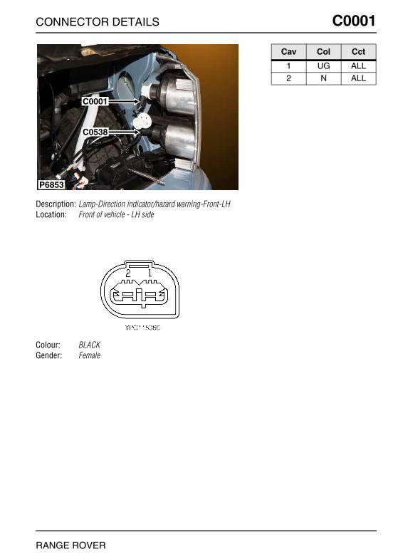
CONNECTOR DETAILS
CONNECTOR DETAILS
RANGE ROVER
C0001
Description: Lamp-Direction indicator/hazard warning-Front-LHLocation: Front of vehicle - LH side
Colour: BLACKGender: Female
P6853
C0001
C0538
RANGE ROVER
C0001
Cav Col Cct
1 UG ALL2 N ALL

O
C0002 CC0002
Description: Lamp-Direction indicator/hazard warning-Front-RHLocation: Front of vehicle - RH side
Colour: BLACKGender: Female
P6863
C0002
C0537
NNECTOR DETAILS
Cav Col Cct
1 UN ALL2 N ALL
RANGE ROVER
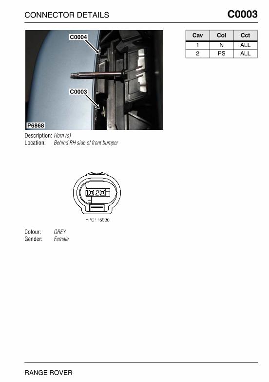
CONNECTOR DETAILS
C0003
Description: Horn (s)Location: Behind RH side of front bumper
Colour: GREYGender: Female
P6868
C0004
C0003
RANGE ROVER
C0003
Cav Col Cct
1 N ALL2 PS ALL
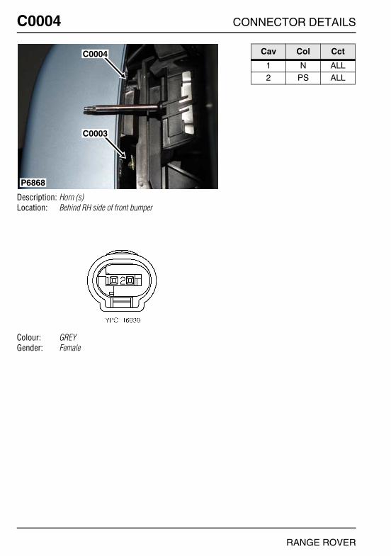
O
C0004 CC0004
Description: Horn (s)Location: Behind RH side of front bumper
Colour: GREYGender: Female
P6868
C0004
C0003
NNECTOR DETAILS
Cav Col Cct
1 N ALL2 PS ALL
RANGE ROVER
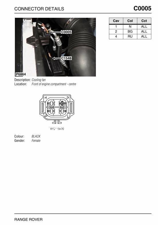
CONNECTOR DETAILS
C0005
Description: Cooling fanLocation: Front of engine compartment - centre
Colour: BLACKGender: Female
P6864
C0005
C1548
RANGE ROVER
C0005
Cav Col Cct
1 N ALL2 BG ALL4 RU ALL

O
C0007 CC0007
Description: Switch-BonnetLocation: Rear RH side of engine compartment
Colour: BLACKGender: Female
P6884
C0666
C0507
C0026
C0030
C0007
NNECTOR DETAILS
Cav Col Cct
1 N ALL3 PG ALL
RANGE ROVER

CONNECTOR DETAILS
C0008
Description: Pump-Washer-WindscreenLocation: Front LH side of engine compartment
Colour: BLACKGender: Female
P6858
C0021
C1342C0008
C0620
RANGE ROVER
C0008
Cav Col Cct
1 B ALL2 N ALL
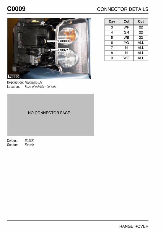
O
C0009 CC0009
Description: Headlamp-LHLocation: Front of vehicle - LH side
Colour: BLACKGender: Female
P6860
C0009
C0071
NNECTOR DETAILS
Cav Col Cct
3 WP 224 GR 225 WB 22
6 YG ALL7 N ALL8 N ALL
9 WG ALL
RANGE ROVER

CONNECTOR DETAILS
C0011
Description: Headlamp-RHLocation: Front of vehicle - RH side
Colour: BLACKGender: Female
P6866
C0011
C0070
C1341
RANGE ROVER
C0011
Cav Col Cct
3 WP 224 GR 225 WB 22
6 WU ALL7 N ALL8 N ALL
9 YU ALL

O
C0012 CC0012
Description: Lamp-Side repeater-Front-RHLocation: Front of vehicle - RH side
Colour: BLACKGender: Female
P6871
C0012
NNECTOR DETAILS
Cav Col Cct
1 N ALL2 UY ALL
RANGE ROVER

CONNECTOR DETAILS
C0013
Description: Lamp-Side repeater-Front-LHLocation: Front of vehicle - LH side
Colour: BLACKGender: Female
P6873
C0013
RANGE ROVER
C0013
Cav Col Cct
1 N ALL2 UY ALL

O
C0017 CC0017
Description: Header -EarthLocation: LH side of engine compartment
Colour: TIN-PLATEGender: Male
P6857
C0362
C0551
C0017
NNECTOR DETAILS
Cav Col Cct
0 N ALL
RANGE ROVER
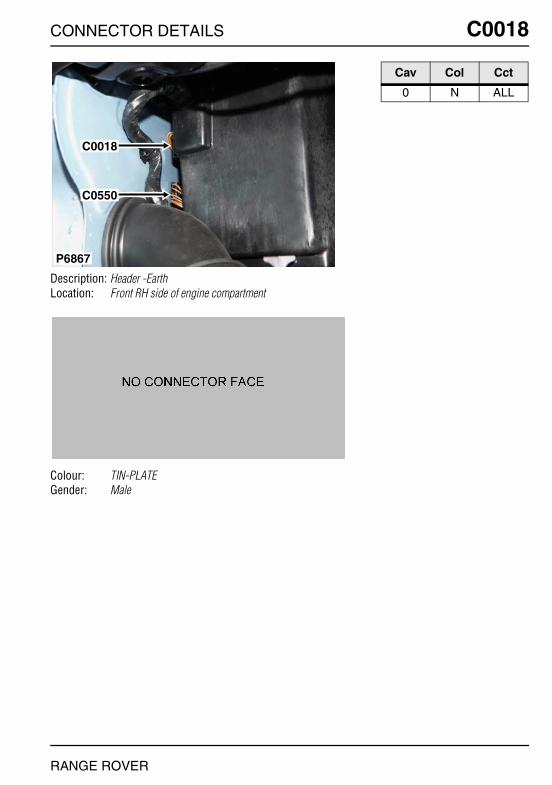
CONNECTOR DETAILS
C0018
Description: Header -EarthLocation: Front RH side of engine compartment
Colour: TIN-PLATEGender: Male
P6867
C0018
C0550
RANGE ROVER
C0018
Cav Col Cct
0 N ALL

O
C0021 CC0021
Description: Pump-Washer-Rear screenLocation: Front LH side of engine compartment
Colour: BLACKGender: Female
P6858
C0021
C1342C0008
C0620
NNECTOR DETAILS
Cav Col Cct
1 BR ALL2 N ALL
RANGE ROVER
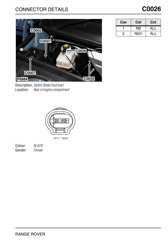
CONNECTOR DETAILS
C0026
Description: Switch-Brake fluid levelLocation: Rear of engine compartment
Colour: BLACKGender: Female
P6884
C0666
C0507
C0026
C0030
C0007
RANGE ROVER
C0026
Cav Col Cct
1 NB ALL2 NGY ALL

O
C0028 CC0028
Description: Switch-Ignition - V8Location: Beneath centre console
Colour: WHITEGender: Female
P6913
C0049C0672
C0028C0099
C0673
NNECTOR DETAILS
Cav Col Cct
1 G 22 PB 25 RU 2
6 R 28 BY 29 G 2
RANGE ROVER
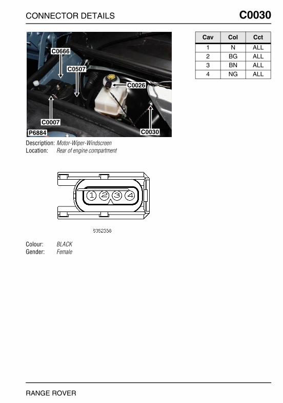
CONNECTOR DETAILS
C0030
Description: Motor-Wiper-WindscreenLocation: Rear of engine compartment
Colour: BLACKGender: Female
P6884
C0666
C0507
C0026
C0030
C0007
RANGE ROVER
C0030
Cav Col Cct
1 N ALL2 BG ALL3 BN ALL
4 NG ALL

O
C0040 CC0040
Description: Diagnostic socketLocation: Behind driver side of fascia
Colour: BLACKGender: Female
P6916
C0040
NNECTOR DETAILS
Cav Col Cct
1 GW ALL4 NB ALL5 NB ALL
7 WPY ALL8 WP ALL9 B ALL
16 RUY ALL
RANGE ROVER

CONNECTOR DETAILS
C0041
Description: Switch-LightingLocation: Behind driver side of fascia
Colour: BLACKGender: Female
P6920
C0041
RANGE ROVER
C0041
Cav Col Cct
1 YG ALL2 B ALL3 SB ALL
7 NB ALL8 YB ALL9 YW ALL
10 G ALL11 Y ALL
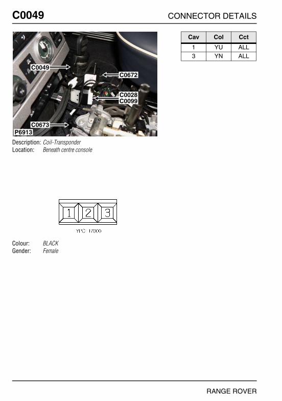
O
C0049 CC0049
Description: Coil-TransponderLocation: Beneath centre console
Colour: BLACKGender: Female
P6913
C0049C0672
C0028C0099
C0673
NNECTOR DETAILS
Cav Col Cct
1 YU ALL3 YN ALL
RANGE ROVER
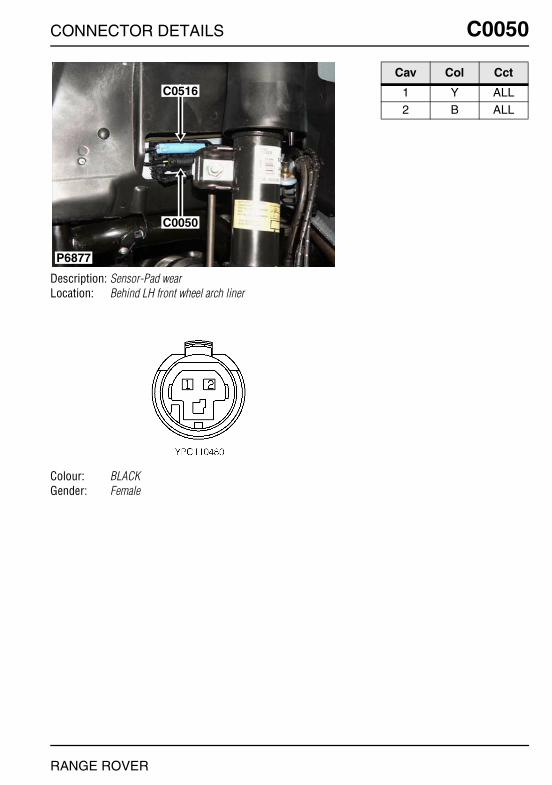
CONNECTOR DETAILS
C0050
Description: Sensor-Pad wearLocation: Behind LH front wheel arch liner
Colour: BLACKGender: Female
P6877
C0516
C0050
RANGE ROVER
C0050
Cav Col Cct
1 Y ALL2 B ALL

O
C0053 CC0053
Description: Alternator/generator - Td6Location: LH side of engine
Colour:Gender:
P7027
C1216
C0053
NNECTOR DETAILS
Cav Col Cct
1 G 31 GW 32 U 3
RANGE ROVER

CONNECTOR DETAILS
C0056
Description: Motor-Blower-FrontLocation: Behind centre of fascia
Colour:Gender:
RANGE ROVER
C0056
Cav Col Cct
1 BG ALL2 RG ALL
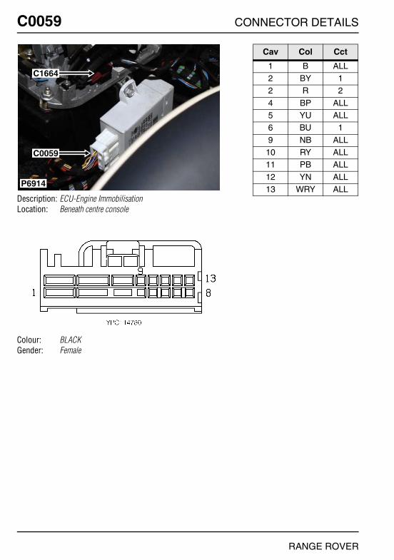
O
C0059 CC0059
Description: ECU-Engine ImmobilisationLocation: Beneath centre console
Colour: BLACKGender: Female
P6914
C1664
C0059
NNECTOR DETAILS
Cav Col Cct
1 B ALL2 BY 12 R 2
4 BP ALL5 YU ALL6 BU 1
9 NB ALL10 RY ALL11 PB ALL
12 YN ALL13 WRY ALL
RANGE ROVER
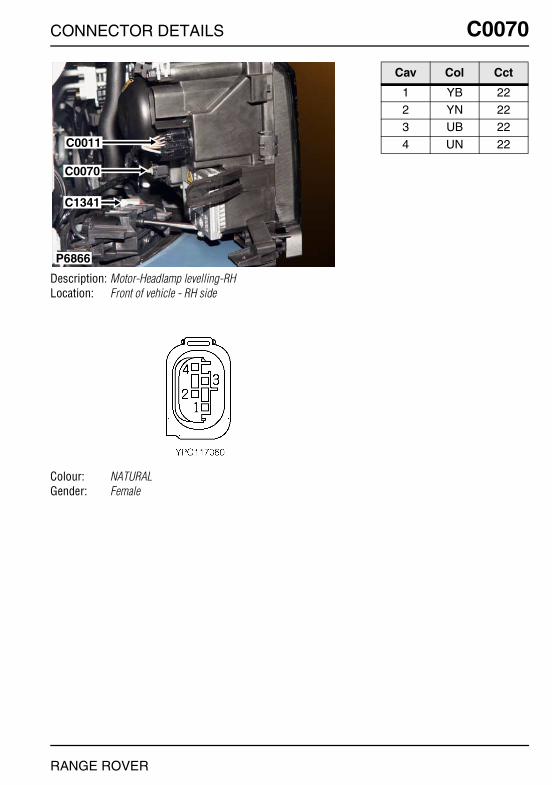
CONNECTOR DETAILS
C0070
Description: Motor-Headlamp levelling-RHLocation: Front of vehicle - RH side
Colour: NATURALGender: Female
P6866
C0011
C0070
C1341
RANGE ROVER
C0070
Cav Col Cct
1 YB 222 YN 223 UB 22
4 UN 22

O
C0071 CC0071
Description: Motor-Headlamp levelling-LHLocation: Front of vehicle - LH side
Colour: NATURALGender: Female
P6860
C0009
C0071
NNECTOR DETAILS
Cav Col Cct
1 YR 222 YN 223 UR 22
4 UN 22
RANGE ROVER

CONNECTOR DETAILS
C0074
Description: Cigar lighter illuminationLocation: Beneath centre console
Colour: WHITEGender: Female
P6911
C0089C0086
C0074
RANGE ROVER
C0074
Cav Col Cct
1 SR ALL
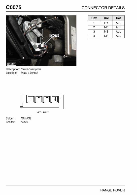
O
C0075 CC0075
Description: Switch-Brake pedalLocation: Driver's footwell
Colour: NATURALGender: Female
P6976
C0075
NNECTOR DETAILS
Cav Col Cct
1 PY ALL2 NB ALL3 NS ALL
4 UR ALL
RANGE ROVER
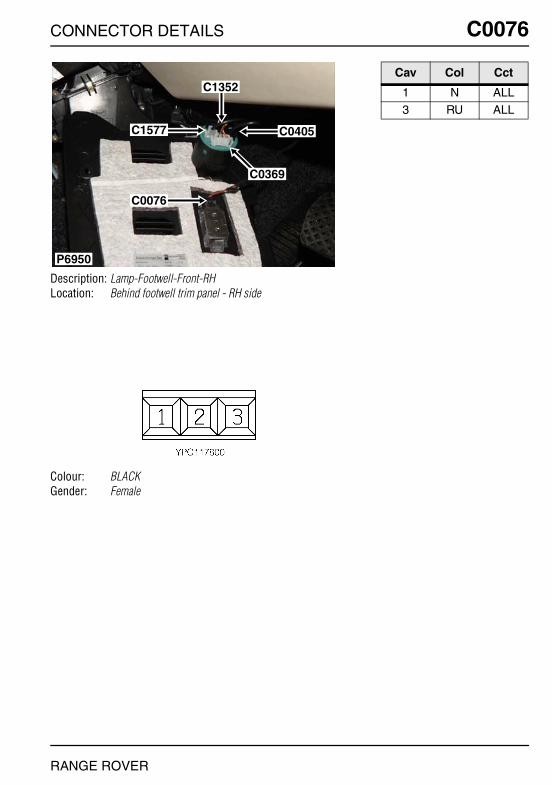
CONNECTOR DETAILS
C0076
Description: Lamp-Footwell-Front-RHLocation: Behind footwell trim panel - RH side
Colour: BLACKGender: Female
P6950
C1352
C1577
C0076
C0405
C0369
RANGE ROVER
C0076
Cav Col Cct
1 N ALL3 RU ALL

O
C0077 CC0077
Description: Lamp-Footwell-Front-LHLocation: Behind footwell trim panel - LH side
Colour: BLACKGender: Female
P6954C0077
NNECTOR DETAILS
Cav Col Cct
1 N ALL3 RU ALL
RANGE ROVER

CONNECTOR DETAILS
C0082
Description: Rotary couplerLocation: Underside of steering column
Colour: GREENGender: Female
P6955
C1393
C0082
C2041
RANGE ROVER
C0082
Cav Col Cct
2 SN ALL3 SB ALL4 YN ALL
5 YB ALL6 NR ALL7 NB ALL
8 YB 79 WSY 7
10 PY 7
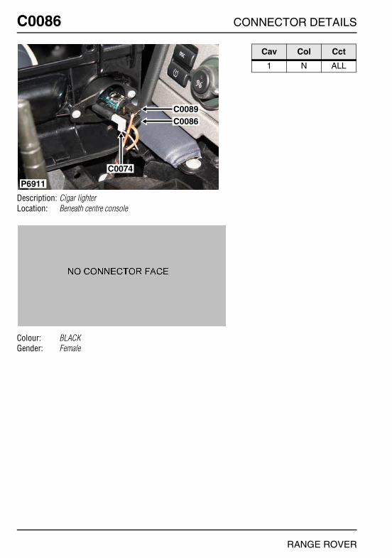
O
C0086 CC0086
Description: Cigar lighterLocation: Beneath centre console
Colour: BLACKGender: Female
P6911
C0089C0086
C0074
NNECTOR DETAILS
Cav Col Cct
1 N ALL
RANGE ROVER

CONNECTOR DETAILS
C0089
Description: Cigar lighterLocation: Beneath centre console
Colour: BLACKGender: Female
P6911
C0089C0086
C0074
RANGE ROVER
C0089
Cav Col Cct
1 RBY ALL

O
C0091 CC0091
Description: Switch-HandbrakeLocation: Beneath centre console
Colour: BRASSGender: Eyelet
P6910
C0350C0942
C2322
C0091
NNECTOR DETAILS
Cav Col Cct
1 UNY ALL
RANGE ROVER

CONNECTOR DETAILS
C0096
Description: Switch-Hazard Warning and CDL MasterLocation: Behind centre console
Colour: BLACKGender: Female
P6928
C1294
C1295
C0096
RANGE ROVER
C0096
Cav Col Cct
2 NB ALL3 NU ALL4 UN ALL
5 YR ALL6 SR ALL
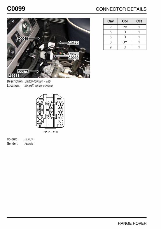
O
C0099 CC0099
Description: Switch-Ignition - Td6Location: Beneath centre console
Colour: BLACKGender: Female
P6913
C0049C0672
C0028C0099
C0673
NNECTOR DETAILS
Cav Col Cct
2 PB 15 R 16 R 1
8 BY 19 G 1
RANGE ROVER
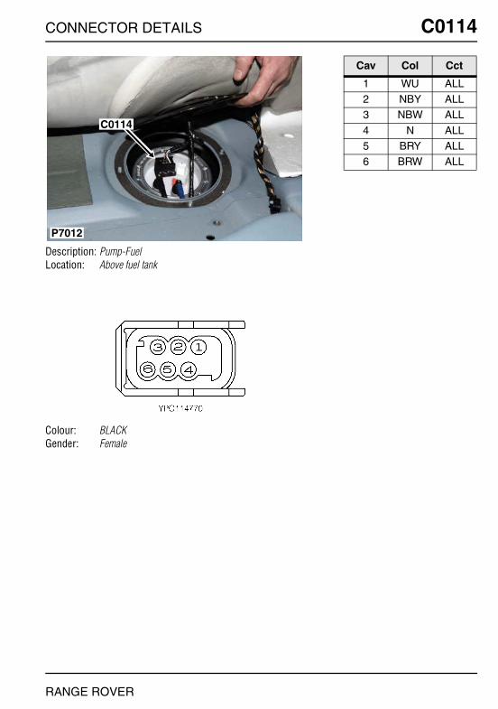
CONNECTOR DETAILS
C0114
Description: Pump-FuelLocation: Above fuel tank
Colour: BLACKGender: Female
P7012
C0114
RANGE ROVER
C0114
Cav Col Cct
1 WU ALL2 NBY ALL3 NBW ALL
4 N ALL5 BRY ALL6 BRW ALL
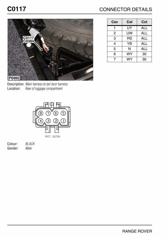
O
C0117 CC0117
Description: Main harness to tail door harnessLocation: Rear of luggage compartment
Colour: BLACKGender: Male
P6960
C0384C0117
NNECTOR DETAILS
Cav Col Cct
1 UY ALL2 UW ALL3 RS ALL
4 YB ALL5 N ALL6 WY 30
7 WY 30
RANGE ROVER
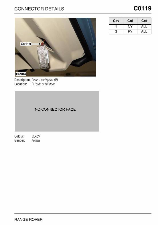
CONNECTOR DETAILS
C0119
Description: Lamp-Load space-RHLocation: RH side of tail door
Colour: BLACKGender: Female
P6984
C0119
RANGE ROVER
C0119
Cav Col Cct
1 NY ALL3 RY ALL
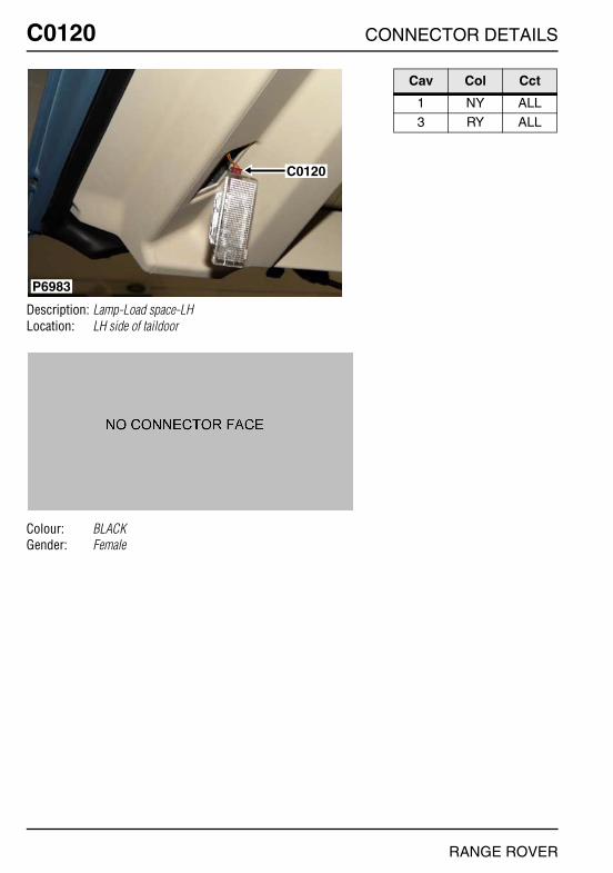
O
C0120 CC0120
Description: Lamp-Load space-LHLocation: LH side of taildoor
Colour: BLACKGender: Female
P6983
C0120
NNECTOR DETAILS
Cav Col Cct
1 NY ALL3 RY ALL
RANGE ROVER
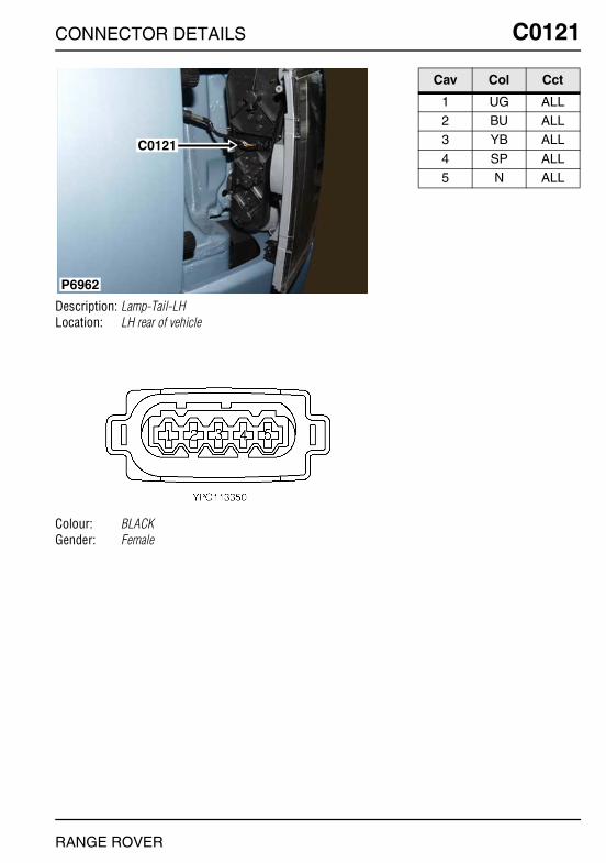
CONNECTOR DETAILS
C0121
Description: Lamp-Tail-LHLocation: LH rear of vehicle
Colour: BLACKGender: Female
C0121
P6962
RANGE ROVER
C0121
Cav Col Cct
1 UG ALL2 BU ALL3 YB ALL
4 SP ALL5 N ALL
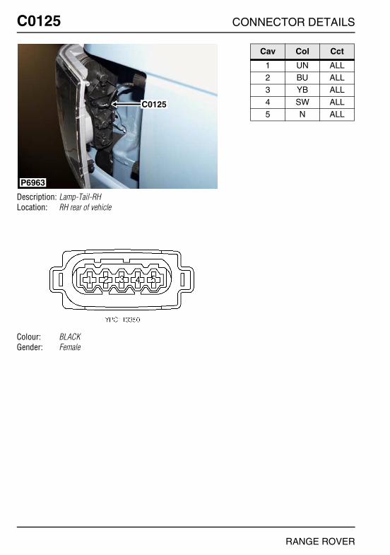
O
C0125 CC0125
Description: Lamp-Tail-RHLocation: RH rear of vehicle
Colour: BLACKGender: Female
P6963
C0125
NNECTOR DETAILS
Cav Col Cct
1 UN ALL2 BU ALL3 YB ALL
4 SW ALL5 N ALL
RANGE ROVER

CONNECTOR DETAILS
C0132
Description: Sensor-Fuel rail pressure - Td6Location: Centre rear of engine
Colour:Gender:
P7028
C0132
C0216
RANGE ROVER
C0132
Cav Col Cct
1 NG 32 UB 33 WY 8
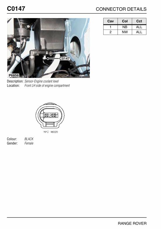
O
C0147 CC0147
Description: Sensor-Engine coolant levelLocation: Front LH side of engine compartment
Colour: BLACKGender: Female
P6856
C0147
NNECTOR DETAILS
Cav Col Cct
1 NB ALL2 NW ALL
RANGE ROVER

CONNECTOR DETAILS
C0149
Description: Sensor-Mass air flow (MAF) - V8Location: Front RH side of engine
Colour:Gender:
C0149
P7038
RANGE ROVER
C0149
Cav Col Cct
1 UW 32 RW 33 B 3
4 RY 35 Y 23

O
C0149 CC0149
Description: Sensor-Mass air flow (MAF) - Td6Location: Top of engine
Colour:Gender:
P7026
C0176
C0149
NNECTOR DETAILS
Cav Col Cct
1 YU 32 RU 33 B 3
4 RG 35 Y 3
RANGE ROVER
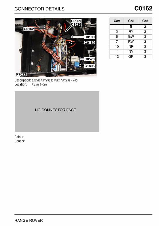
CONNECTOR DETAILS
C0162
Description: Engine harness to main harness - Td6Location: Inside E-box
Colour:Gender:
P7022
C0162
C0909C1526
C0190
C0189
C0570
C1895
RANGE ROVER
C0162
Cav Col Cct
1 B 32 RY 36 GW 3
7 RW 310 NP 311 NY 3
12 GR 3
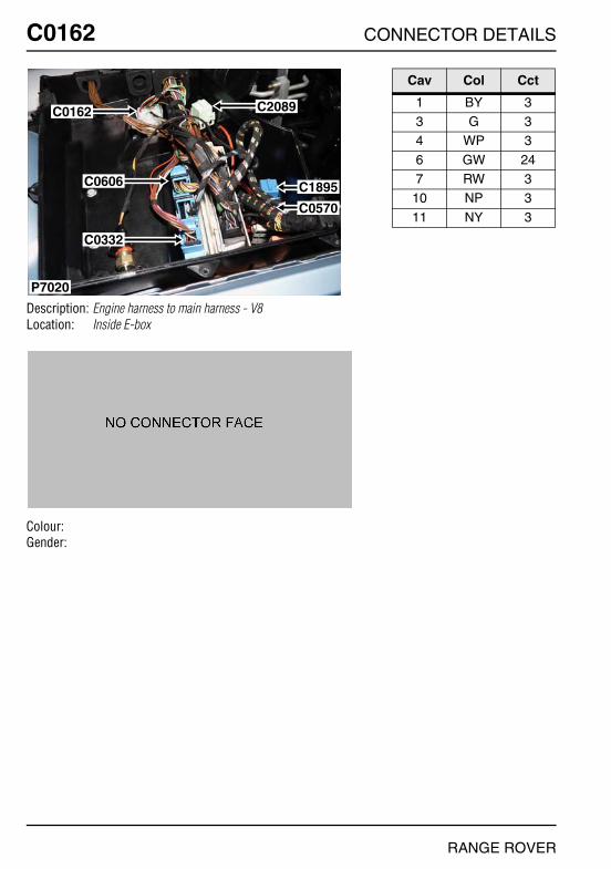
O
C0162 CC0162
Description: Engine harness to main harness - V8Location: Inside E-box
Colour:Gender:
P7020
C0162
C0606
C0332
C2089
C1895
C0570
NNECTOR DETAILS
Cav Col Cct
1 BY 33 G 34 WP 3
6 GW 247 RW 3
10 NP 3
11 NY 3
RANGE ROVER

CONNECTOR DETAILS
C0168
Description: Sensor-Crankshaft position (CKP) - Td6Location: LH side of engine
Colour:Gender:
C0168
P7035
RANGE ROVER
C0168
Cav Col Cct
1 B 32 Y 3
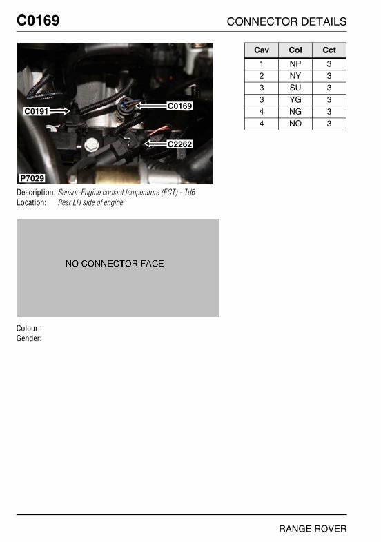
O
C0169 CC0169
Description: Sensor-Engine coolant temperature (ECT) - Td6Location: Rear LH side of engine
Colour:Gender:
C0169
C2262
P7029
C0191
NNECTOR DETAILS
Cav Col Cct
1 NP 32 NY 33 SU 3
3 YG 34 NG 34 NO 3
RANGE ROVER
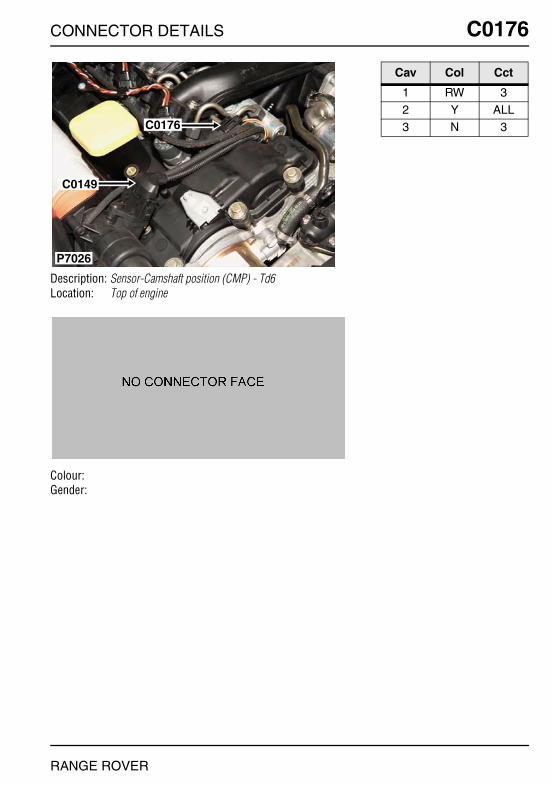
CONNECTOR DETAILS
C0176
Description: Sensor-Camshaft position (CMP) - Td6Location: Top of engine
Colour:Gender:
P7026
C0176
C0149
RANGE ROVER
C0176
Cav Col Cct
1 RW 32 Y ALL3 N 3

O
C0179 CC0179
Description: Solenoid-Starter motor - Td6Location: LH side of engine
Colour:Gender:
P7034
C0823C0179
C0178
NNECTOR DETAILS
Cav Col Cct
1 B 3
RANGE ROVER
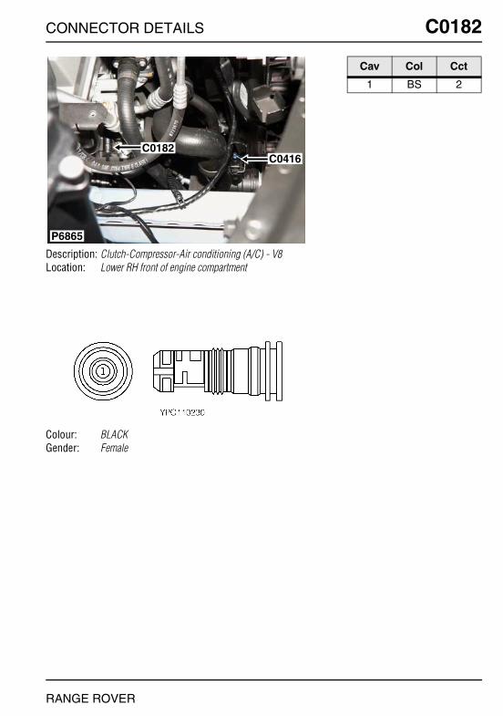
CONNECTOR DETAILS
C0182
Description: Clutch-Compressor-Air conditioning (A/C) - V8Location: Lower RH front of engine compartment
Colour: BLACKGender: Female
P6865
C0182C0416
RANGE ROVER
C0182
Cav Col Cct
1 BS 2
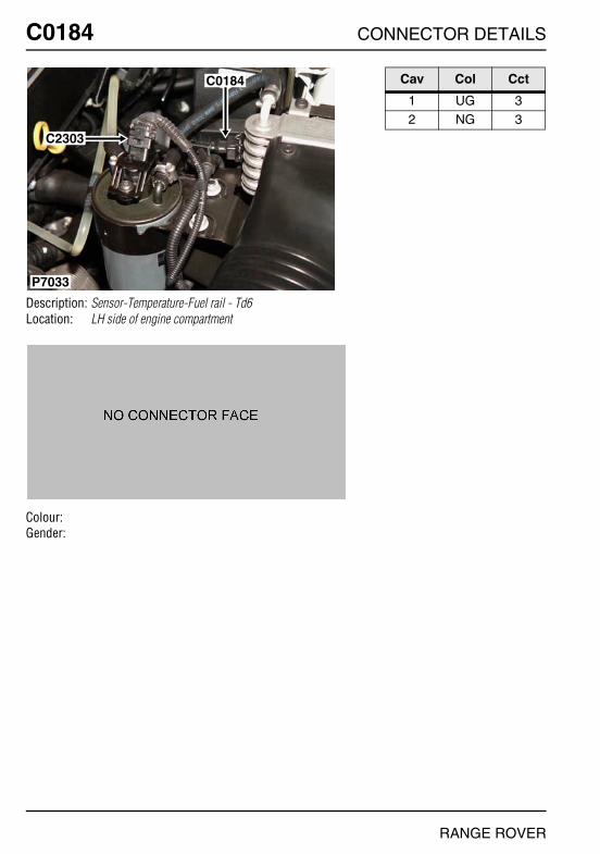
O
C0184 CC0184
Description: Sensor-Temperature-Fuel rail - Td6Location: LH side of engine compartment
Colour:Gender:
P7033
C2303
C0184
NNECTOR DETAILS
Cav Col Cct
1 UG 32 NG 3
RANGE ROVER

CONNECTOR DETAILS
C0187
Description: Switch-Oil pressureLocation: Front LH side of engine compartment
Colour: BLACKGender: Female
P6855
C0556
C0187
RANGE ROVER
C0187
Cav Col Cct
1 NG 2
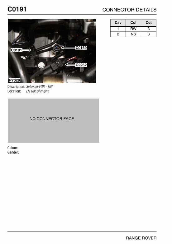
O
C0191 CC0191
Description: Solenoid-EGR - Td6Location: LH side of engine
Colour:Gender:
C0169
C2262
P7029
C0191
NNECTOR DETAILS
Cav Col Cct
1 RW 32 NS 3
RANGE ROVER
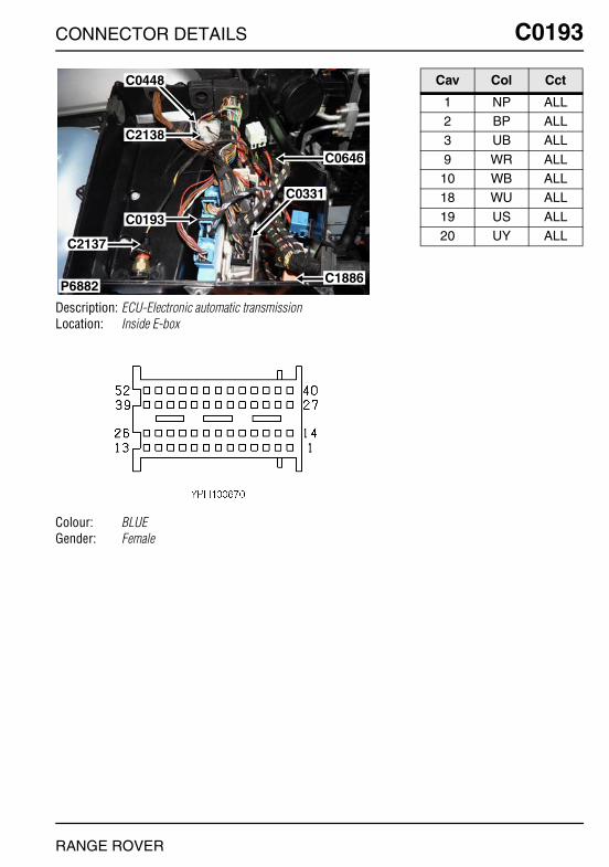
CONNECTOR DETAILS
C0193
Description: ECU-Electronic automatic transmissionLocation: Inside E-box
Colour: BLUEGender: Female
P6882
C0448
C2138
C0193
C0331
C1886
C0646
C2137
RANGE ROVER
C0193
Cav Col Cct
1 NP ALL2 BP ALL3 UB ALL
9 WR ALL10 WB ALL18 WU ALL
19 US ALL20 UY ALL
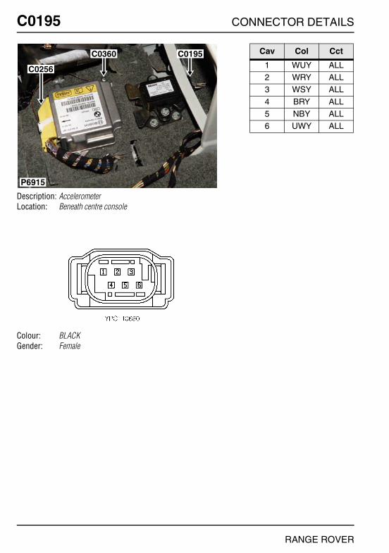
O
C0195 CC0195
Description: AccelerometerLocation: Beneath centre console
Colour: BLACKGender: Female
P6915
C0256
C0360 C0195
NNECTOR DETAILS
Cav Col Cct
1 WUY ALL2 WRY ALL3 WSY ALL
4 BRY ALL5 NBY ALL6 UWY ALL
RANGE ROVER
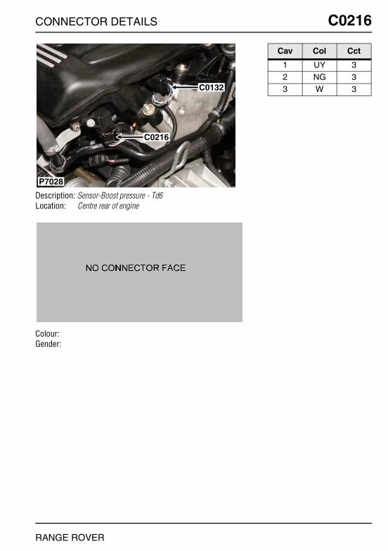
CONNECTOR DETAILS
C0216
Description: Sensor-Boost pressure - Td6Location: Centre rear of engine
Colour:Gender:
P7028
C0132
C0216
RANGE ROVER
C0216
Cav Col Cct
1 UY 32 NG 33 W 3

O
C0230 CC0230
Description: Instrument PackLocation: Behind instrument pack
Colour: BLACKGender: Female
P6925
C0233
C0230
C0234
NNECTOR DETAILS
Cav Col Cct
1 NB ALL3 U ALL4 NG ALL
5 UNY ALL7 RY ALL8 SR ALL
13 NP ALL15 SB ALL17 GU ALL
RANGE ROVER
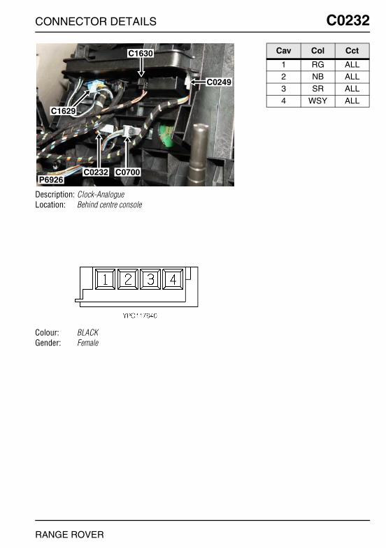
CONNECTOR DETAILS
C0232
Description: Clock-AnalogueLocation: Behind centre console
Colour: BLACKGender: Female
P6926C0232 C0700
C1629
C1630
C0249
RANGE ROVER
C0232
Cav Col Cct
1 RG ALL2 NB ALL3 SR ALL
4 WSY ALL

O
C0233 CC0233
Description: Instrument PackLocation: Behind instrument pack
Colour: BLACKGender: Female
P6925
C0233
C0230
C0234
NNECTOR DETAILS
Cav Col Cct
1 WP ALL3 BW 157 WRY ALL
8 WSY ALL9 NB ALL
10 NB ALL
11 BR ALL12 PG ALL14 BG ALL
15 RY ALL16 GU ALL17 WU ALL
18 WR ALL
RANGE ROVER

CONNECTOR DETAILS
C0234
Description: Instrument PackLocation: Behind instrument pack
Colour: GREYGender: Female
P6925
C0233
C0230
C0234
RANGE ROVER
C0234
Cav Col Cct
1 NR ALL4 Y ALL5 YR ALL
7 BRY ALL8 YB 19 YN 1
12 NBY ALL14 UR ALL16 NBW ALL
18 NY ALL19 NP ALL20 YN ALL
22 UN ALL23 BRW ALL25 SP ALL

O
C0243 CC0243
Description: Selector-Automatic transmissionLocation: Beneath centre console
Colour: BLACKGender: Female
P6909
C0675
C0245
C0243
NNECTOR DETAILS
Cav Col Cct
1 WG ALL3 BG ALL6 GBY ALL
RANGE ROVER
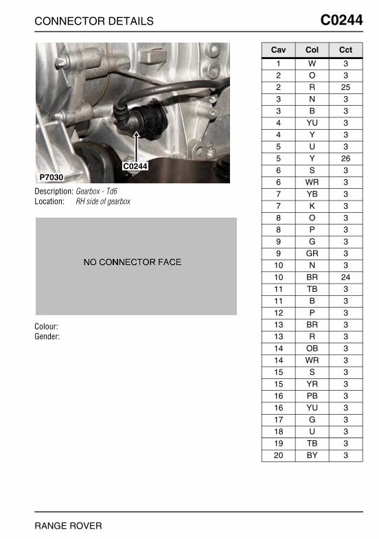
CONNECTOR DETAILS
C0244
Description: Gearbox - Td6Location: RH side of gearbox
Colour:Gender:
C0244P7030
RANGE ROVER
C0244
Cav Col Cct
1 W 32 O 32 R 25
3 N 33 B 34 YU 3
4 Y 35 U 35 Y 26
6 S 36 WR 37 YB 3
7 K 38 O 38 P 3
9 G 39 GR 3
10 N 3
10 BR 2411 TB 311 B 3
12 P 313 BR 313 R 3
14 OB 314 WR 315 S 3
15 YR 316 PB 316 YU 3
17 G 318 U 319 TB 3
20 BY 3

O
C0245 CC0245
Description: Lamp-Automatic gearbox selector indicatorLocation: Beneath centre console
Colour: WHITEGender: Female
P6909
C0675
C0245
C0243
NNECTOR DETAILS
Cav Col Cct
1 SR ALL2 NB ALL3 RY 27
RANGE ROVER

CONNECTOR DETAILS
C0246
Description: Heated screen-FrontLocation: Behind RH side of fascia
Colour: BLACKGender: Male
P6919
C0246
C2081
RANGE ROVER
C0246
Cav Col Cct
1 N 92 B 9
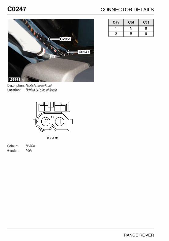
O
C0247 CC0247
Description: Heated screen-FrontLocation: Behind LH side of fascia
Colour: BLACKGender: Male
P6921
C2051
C0247
NNECTOR DETAILS
Cav Col Cct
1 N 92 B 9
RANGE ROVER
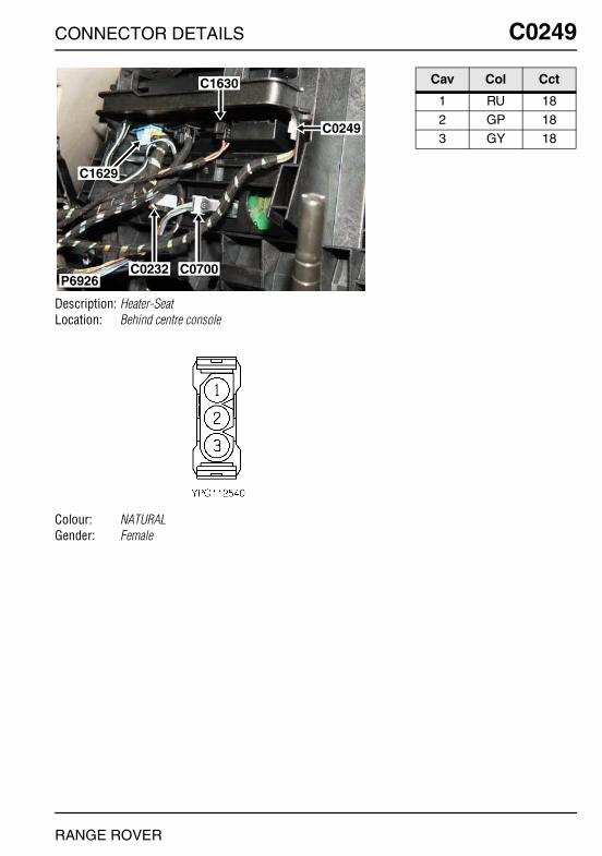
CONNECTOR DETAILS
C0249
Description: Heater-SeatLocation: Behind centre console
Colour: NATURALGender: Female
P6926C0232 C0700
C1629
C1630
C0249
RANGE ROVER
C0249
Cav Col Cct
1 RU 182 GP 183 GY 18

O
C0251 CC0251
Description: Air bag-PassengerLocation: Behind passenger side of fascia
Colour: BLACKGender: Male
P6957
C0251
NNECTOR DETAILS
Cav Col Cct
1 UB ALL2 UN ALL3 WB ALL
4 WN ALL
RANGE ROVER
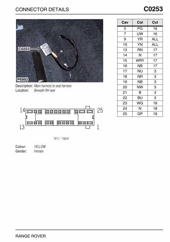
CONNECTOR DETAILS
C0253
Description: Main harness to seat harnessLocation: Beneath RH seat
Colour: YELLOWGender: Female
P6993
C0253
RANGE ROVER
C0253
Cav Col Cct
5 PG 167 UW 169 YR ALL
10 YN ALL13 RN 1714 N 17
15 WRY 1716 NB 1717 NU 3
18 NR 319 NB 320 NW 3
21 B 322 BU 323 WG 18
24 N 1825 GP 18
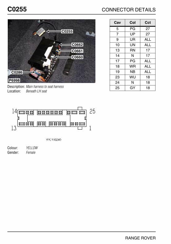
O
C0255 CC0255
Description: Main harness to seat harnessLocation: Beneath LH seat
Colour: YELLOWGender: Female
P6998
C0662
C0661
C0660
C0286
C0255
NNECTOR DETAILS
Cav Col Cct
5 PG 277 UP 279 UR ALL
10 UN ALL13 RN 1714 N 17
17 PG ALL18 WR ALL19 NB ALL
23 WU 1824 N 1825 GY 18
RANGE ROVER

CONNECTOR DETAILS
C0256
Description: DCU-AirbagLocation: Beneath centre console
Colour: NATURALGender: Female
P6915
C0256
C0360 C0195
RANGE ROVER
C0256
Cav Col Cct
1 YR ALL2 YN ALL3 UR ALL
4 UN ALL5 PU ALL6 NB ALL
7 NP ALL8 UP 279 WRY ALL
10 YB ALL11 YN ALL12 UW 16
13 UB ALL14 UN ALL15 WR ALL
16 Y ALL17 N ALL18 U ALL
19 N ALL20 YG ALL21 YR ALL
26 SB ALL27 SN ALL28 Y 20
29 B 2033 WB ALL34 SU ALL
40 WN ALL41 G 2042 B 20
45 Y ALL46 UY ALL47 W ALL
48 UW ALL49 N ALL50 NR ALL
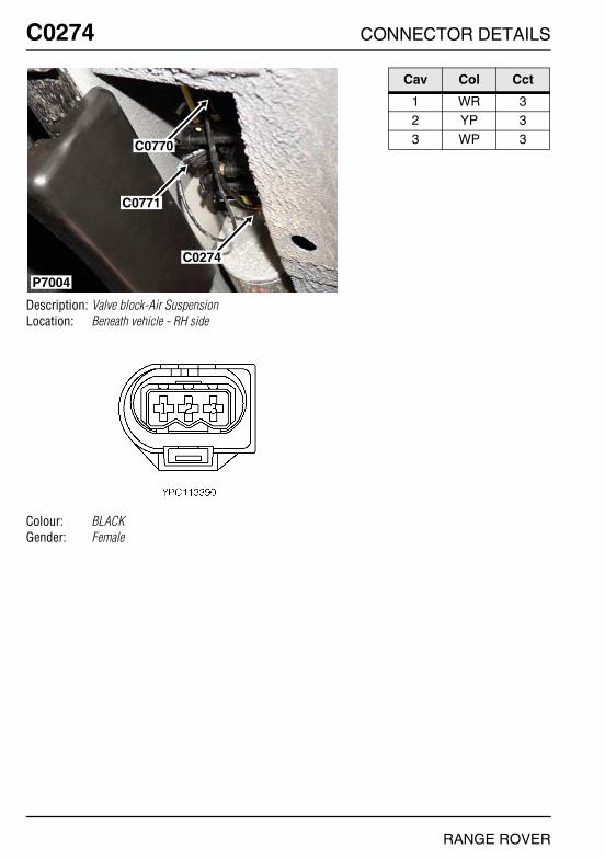
O
C0274 CC0274
Description: Valve block-Air SuspensionLocation: Beneath vehicle - RH side
Colour: BLACKGender: Female
P7004
C0770
C0771
C0274
NNECTOR DETAILS
Cav Col Cct
1 WR 32 YP 33 WP 3
RANGE ROVER
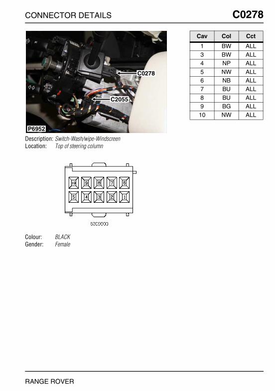
CONNECTOR DETAILS
C0278
Description: Switch-Wash/wipe-WindscreenLocation: Top of steering column
Colour: BLACKGender: Female
P6952
C0278
C2055
RANGE ROVER
C0278
Cav Col Cct
1 BW ALL3 BW ALL4 NP ALL
5 NW ALL6 NB ALL7 BU ALL
8 BU ALL9 BG ALL
10 NW ALL

O
C0286 CC0286
Description: HeaderLocation: Beneath front passenger's seat
Colour:Gender:
P6998
C0662
C0661
C0660
C0286
C0255
NNECTOR DETAILS
Cav Col Cct
0 UR 30 RU 120 RY 17
0 WRY ALL0 B 270 W ALL
0 U 301 W ALL1 UR ALL
1 U ALL1 WRY ALL0 SR ALL
1 RY ALL0 RY ALL1 RY ALL
0 RY ALL1 RY ALL1 B ALL
1 RU ALL1 SR ALL
RANGE ROVER

CONNECTOR DETAILS
C0304
Description: Motor-Window-RearLocation: Behind rear door trim panel
Colour: BLACKGender: Female
C0304
P6905
RANGE ROVER
C0304
Cav Col Cct
1 BG 32 US 3

O
C0310 CC0310
Description: Speaker-Low range-Rear-RHLocation: Behind rear door trim panel
Colour: BLACKGender: Female
P6904
C0310
C2212
NNECTOR DETAILS
Cav Col Cct
1 N ALL2 Y ALL
RANGE ROVER

CONNECTOR DETAILS
C0311
Description: Speaker-Mid range-Rear-RHLocation: Behind rear door trim panel
Colour: WHITEGender: Female
P6903
C0732C2015
C0311
RANGE ROVER
C0311
Cav Col Cct
1 YN 282 YB 28
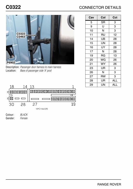
O
C0322 CC0322
Description: Passenger door harness to main harnessLocation: Base of passenger side 'A' post
Colour: BLACKGender: Female
P6902
C0322C0463
NNECTOR DETAILS
Cav Col Cct
5 SR 39 U 3
10 N 3
11 RU 1214 UB 2815 UN 28
16 UY 2817 N 2819 RG 13
20 WG 2621 WY 2623 UR 3
26 N 327 RW 328 UR ALL
29 UN ALL
RANGE ROVER
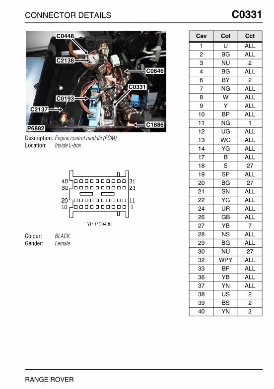
CONNECTOR DETAILS
C0331
Description: Engine control module (ECM)Location: Inside E-box
Colour: BLACKGender: Female
P6882
C0448
C2138
C0193
C0331
C1886
C0646
C2137
RANGE ROVER
C0331
Cav Col Cct
1 U ALL2 BG ALL3 NU 2
4 BG ALL6 BY 27 NG ALL
8 W ALL9 Y ALL
10 BP ALL
11 NG 112 UG ALL13 WG ALL
14 YG ALL17 B ALL18 S 27
19 SP ALL20 BG 2721 SN ALL
22 YG ALL24 UR ALL26 GB ALL
27 YB 728 NS ALL29 BG ALL
30 NU 2732 WPY ALL33 BP ALL
36 YB ALL37 YN ALL38 US 2
39 BS 240 YN 2

O
C0332 CC0332
Description: Engine control module (ECM) - V8Location: Inside E-box
Colour:Gender:
P7020
C0162
C0606
C0332
C2089
C1895
C0570
NNECTOR DETAILS
Cav Col Cct
1 BY 262 BU 33 BR 3
4 BY 35 N 36 BW 3
7 BU 38 BW 39 BR 3
RANGE ROVER

CONNECTOR DETAILS
C0332
Description: Engine control module (ECM) - Td6Location: Inside E-box
Colour: BLUEGender: Male
P7020
C0162
C0606
C0332
C2089
C1895
C0570
RANGE ROVER
C0332
Cav Col Cct
1 RW 33 N 34 RW 3
5 N 36 N 37 N 3
8 N 39 N 3
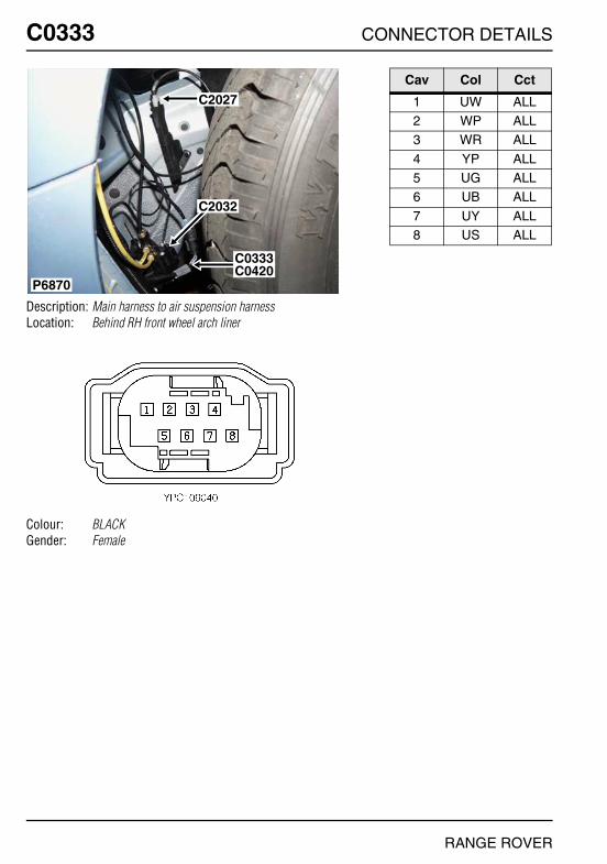
O
C0333 CC0333
Description: Main harness to air suspension harnessLocation: Behind RH front wheel arch liner
Colour: BLACKGender: Female
P6870
C2032
C0333C0420
C2027
NNECTOR DETAILS
Cav Col Cct
1 UW ALL2 WP ALL3 WR ALL
4 YP ALL5 UG ALL6 UB ALL
7 UY ALL8 US ALL
RANGE ROVER
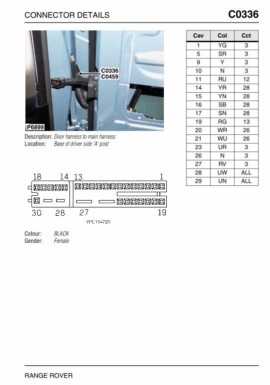
CONNECTOR DETAILS
C0336
Description: Door harness to main harnessLocation: Base of driver side 'A' post
Colour: BLACKGender: Female
P6899
C0336C0459
RANGE ROVER
C0336
Cav Col Cct
1 YG 35 SR 39 Y 3
10 N 311 RU 1214 YR 28
15 YN 2816 SB 2817 SN 28
19 RG 1320 WR 2621 WU 26
23 UR 326 N 327 RV 3
28 UW ALL29 UN ALL

O
C0350 CC0350
Description: Socket-Accessory-RearLocation: Luggage compartment - RH side
Colour:Gender:
P6959
C2047C0350
NNECTOR DETAILS
Cav Col Cct
1 RB ALL2 N ALL
RANGE ROVER

CONNECTOR DETAILS
C0350
Description: Socket-Accessory-FrontLocation: Beneath centre console
Colour: WHITEGender: Female
P6910
C0350C0942
C2322
C0091
RANGE ROVER
C0350
Cav Col Cct
1 RG 3

O
C0353 CC0353
Description: Mirror-Door-Passenger sideLocation: Behind passenger's door trim panel
Colour:Gender:
P6892
C0531
C0353C0600
NNECTOR DETAILS
Cav Col Cct
1 WG 262 WY 263 N 13
4 RG 13
RANGE ROVER
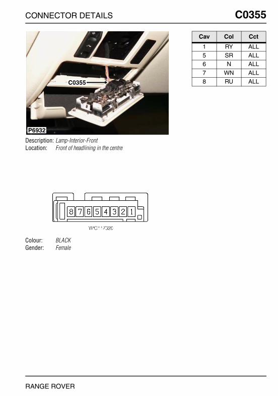
CONNECTOR DETAILS
C0355
Description: Lamp-Interior-FrontLocation: Front of headlining in the centre
Colour: BLACKGender: Female
P6932
C0355
RANGE ROVER
C0355
Cav Col Cct
1 RY ALL5 SR ALL6 N ALL
7 WN ALL8 RU ALL

O
C0357 CC0357
Description: Lamp-Interior-RearLocation: Behind centre headlining
Colour: NATURALGender: Female
P6935
C0357C0359
NNECTOR DETAILS
Cav Col Cct
1 RY ALL5 SR ALL6 N ALL
7 RY ALL8 RU ALL
RANGE ROVER

CONNECTOR DETAILS
C0359
Description: Sensor-VolumetricLocation: Behind centre headlining
Colour: BLACKGender: Female
P6935
C0357C0359
RANGE ROVER
C0359
Cav Col Cct
1 NB ALL2 BW ALL3 BY ALL
4 RW ALL

O
C0360 CC0360
Description: Earth-SRSLocation: Beneath centre console
Colour: TIN-PLATEGender: Eyelet
P6915
C0256
C0360 C0195
NNECTOR DETAILS
Cav Col Cct
1 NB ALL
RANGE ROVER

CONNECTOR DETAILS
C0362
Description: Earth-ABSLocation: Rear LH side of engine compartment
Colour: TIN-PLATEGender: Eyelet
P6857
C0362
C0551
C0017
RANGE ROVER
C0362
Cav Col Cct
1 N ALL2 N ALL

O
C0363 CC0363
Description: Switch-Sunroof-FrontLocation: Front of headlining in the centre
Colour: BLACKGender: Female
P6931
C1303
C0363
NNECTOR DETAILS
Cav Col Cct
2 SR 33 YW 34 YG 3
5 SB 36 YS 3
RANGE ROVER
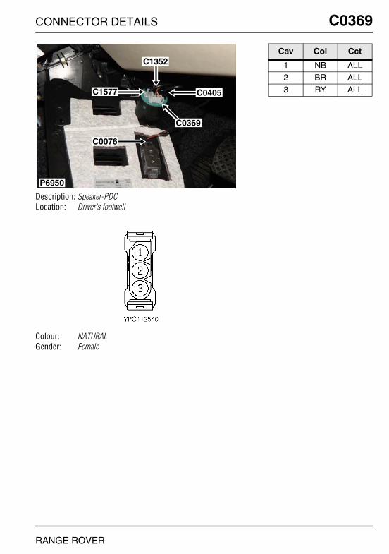
CONNECTOR DETAILS
C0369
Description: Speaker-PDCLocation: Driver's footwell
Colour: NATURALGender: Female
P6950
C1352
C1577
C0076
C0405
C0369
RANGE ROVER
C0369
Cav Col Cct
1 NB ALL2 BR ALL3 RY ALL

O
C0381 CC0381
Description: Heated rear window (HRW)Location: LH side of taildoor
Colour: BLACKGender: Female
P6987
C0381
NNECTOR DETAILS
Cav Col Cct
1 B ALL
RANGE ROVER

CONNECTOR DETAILS
C0382
Description: Heated rear window (HRW)Location: RH side of tail door
Colour: BLACKGender: Female
P6988
C0382
RANGE ROVER
C0382
Cav Col Cct
1 N ALL

O
C0383 CC0383
Description: Motor-Lock-Tail doorLocation: Centre of taildoor, behind trim panel
Colour: BLACKGender: Female
P6989
C1495
C0383
NNECTOR DETAILS
Cav Col Cct
1 NY ALL2 SW ALL3 N ALL
4 YN ALL
RANGE ROVER
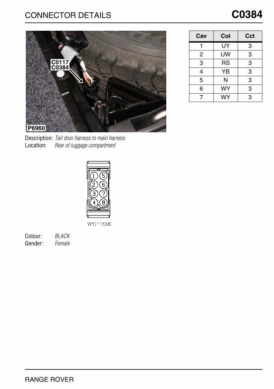
CONNECTOR DETAILS
C0384
Description: Tail door harness to main harnessLocation: Rear of luggage compartment
Colour: BLACKGender: Female
P6960
C0384C0117
RANGE ROVER
C0384
Cav Col Cct
1 UY 32 UW 33 RS 3
4 YB 35 N 36 WY 3
7 WY 3

O
C0388 CC0388
Description: Motor-Wiper-Rear screenLocation: Centre of taildoor, behind trim panel
Colour: BLACKGender: Female
P6986
C0832
C0835 C0388
NNECTOR DETAILS
Cav Col Cct
1 N ALL2 RW ALL3 BR ALL
RANGE ROVER
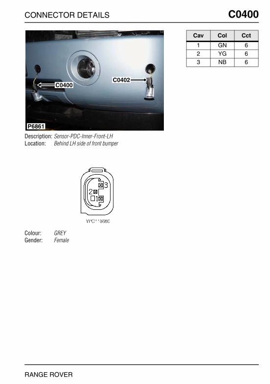
CONNECTOR DETAILS
C0400
Description: Sensor-PDC-Inner-Front-LHLocation: Behind LH side of front bumper
Colour: GREYGender: Female
P6861
C0400C0402
RANGE ROVER
C0400
Cav Col Cct
1 GN 62 YG 63 NB 6
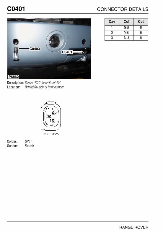
O
C0401 CC0401
Description: Sensor-PDC-Inner-Front-RHLocation: Behind RH side of front bumper
Colour: GREYGender: Female
P6862
C0403C0401
NNECTOR DETAILS
Cav Col Cct
1 GS 62 YB 63 NU 6
RANGE ROVER

CONNECTOR DETAILS
C0402
Description: Sensor-PDC-Outer-Front-LHLocation: Behind LH side of front bumper
Colour: GREYGender: Female
P6861
C0400C0402
RANGE ROVER
C0402
Cav Col Cct
1 GB 62 YS 63 NW 6

O
C0403 CC0403
Description: Sensor-PDC-Outer-Front-RHLocation: Behind RH side of front bumper
Colour: GREYGender: Female
P6862
C0403C0401
NNECTOR DETAILS
Cav Col Cct
1 GP 62 YN 63 NY 6
RANGE ROVER

CONNECTOR DETAILS
C0405
Description: Speaker-PDCLocation: Driver's footwell
Colour: BLACKGender: Female
P6950
C1352
C1577
C0076
C0405
C0369
RANGE ROVER
C0405
Cav Col Cct
1 US 6

O
C0416 CC0416
Description: Sensor-Temperature-Heater coolantLocation: Lower RH front of engine compartment
Colour:Gender:
P6865
C0182C0416
NNECTOR DETAILS
Cav Col Cct
1 US 22 NB 2
RANGE ROVER
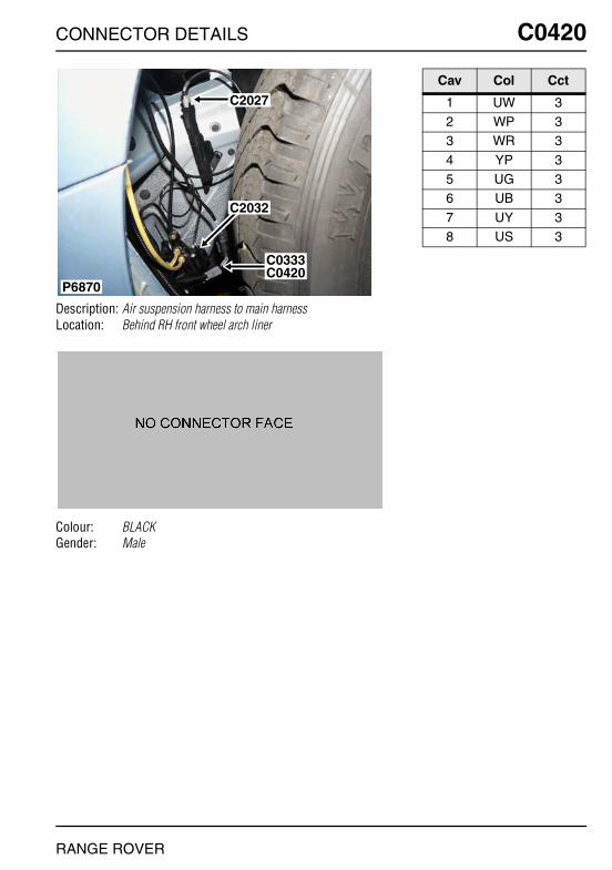
CONNECTOR DETAILS
C0420
Description: Air suspension harness to main harnessLocation: Behind RH front wheel arch liner
Colour: BLACKGender: Male
P6870
C2032
C0333C0420
C2027
RANGE ROVER
C0420
Cav Col Cct
1 UW 32 WP 33 WR 3
4 YP 35 UG 36 UB 3
7 UY 38 US 3
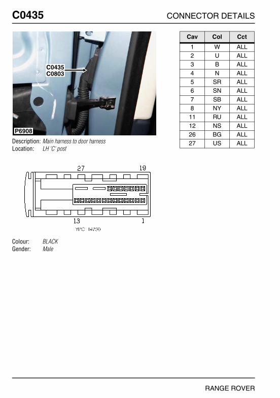
O
C0435 CC0435
Description: Main harness to door harnessLocation: LH 'C' post
Colour: BLACKGender: Male
P6908
C0435C0803
NNECTOR DETAILS
Cav Col Cct
1 W ALL2 U ALL3 B ALL
4 N ALL5 SR ALL6 SN ALL
7 SB ALL8 NY ALL
11 RU ALL
12 NS ALL26 BG ALL27 US ALL
RANGE ROVER

CONNECTOR DETAILS
C0436
Description: Main harness to door harnessLocation: RH 'C' post
Colour: BLACKGender: Male
P6907
C0803C0436
RANGE ROVER
C0436
Cav Col Cct
1 W ALL2 U ALL3 B ALL
4 N ALL5 SR ALL6 SY ALL
7 SU ALL8 NR ALL
11 RU ALL
12 NW ALL26 BN ALL27 UP ALL

O
C0442 CC0442
Description: Motor-Door lock-RearLocation: Behind rear door trim panel
Colour: BLUEGender: Female
P6906
C0442
NNECTOR DETAILS
Cav Col Cct
4 W 35 N 126 NS 12
7 U 38 B 3
RANGE ROVER
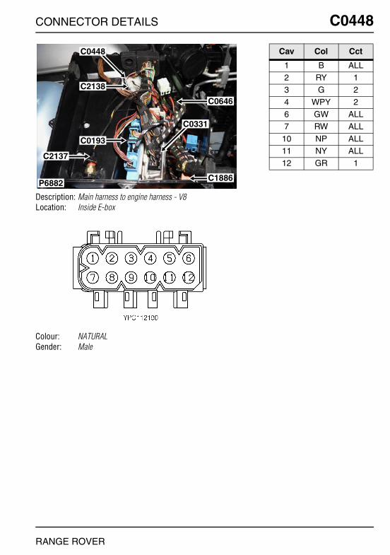
CONNECTOR DETAILS
C0448
Description: Main harness to engine harness - V8Location: Inside E-box
Colour: NATURALGender: Male
P6882
C0448
C2138
C0193
C0331
C1886
C0646
C2137
RANGE ROVER
C0448
Cav Col Cct
1 B ALL2 RY 13 G 2
4 WPY 26 GW ALL7 RW ALL
10 NP ALL11 NY ALL12 GR 1
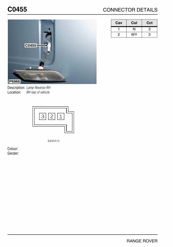
O
C0455 CC0455
Description: Lamp-Reverse-RHLocation: RH rear of vehicle
Colour:Gender:
P6966
C0455
NNECTOR DETAILS
Cav Col Cct
1 N 32 WY 3
RANGE ROVER

CONNECTOR DETAILS
C0459
Description: Main harness to door harnessLocation: Base of driver side 'A' post
Colour: BLACKGender: Male
P6899
C0336C0459
RANGE ROVER
C0459
Cav Col Cct
1 YG ALL5 SR ALL9 Y ALL
10 N ALL11 RU ALL19 RG 12
20 WR 2621 WU 2623 UR ALL
26 N ALL27 RP ALL
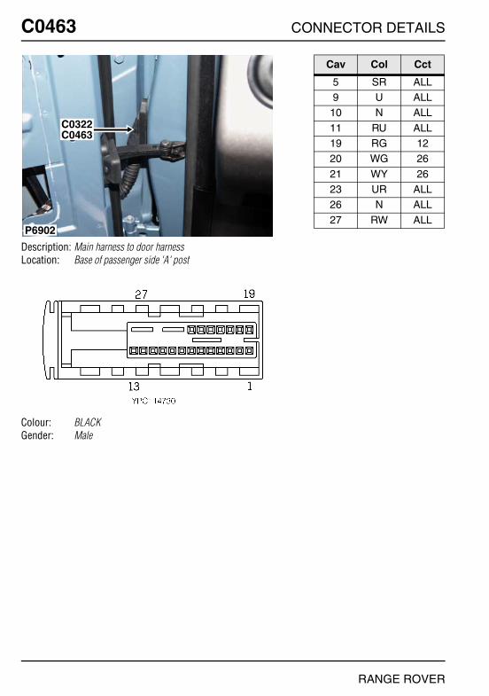
O
C0463 CC0463
Description: Main harness to door harnessLocation: Base of passenger side 'A' post
Colour: BLACKGender: Male
P6902
C0322C0463
NNECTOR DETAILS
Cav Col Cct
5 SR ALL9 U ALL
10 N ALL
11 RU ALL19 RG 1220 WG 26
21 WY 2623 UR ALL26 N ALL
27 RW ALL
RANGE ROVER

CONNECTOR DETAILS
C0472
Description: Lamp-Reverse-LHLocation: LH rear of vehicle
Colour:Gender:
P6967
C0472
RANGE ROVER
C0472
Cav Col Cct
1 N 32 WY 3
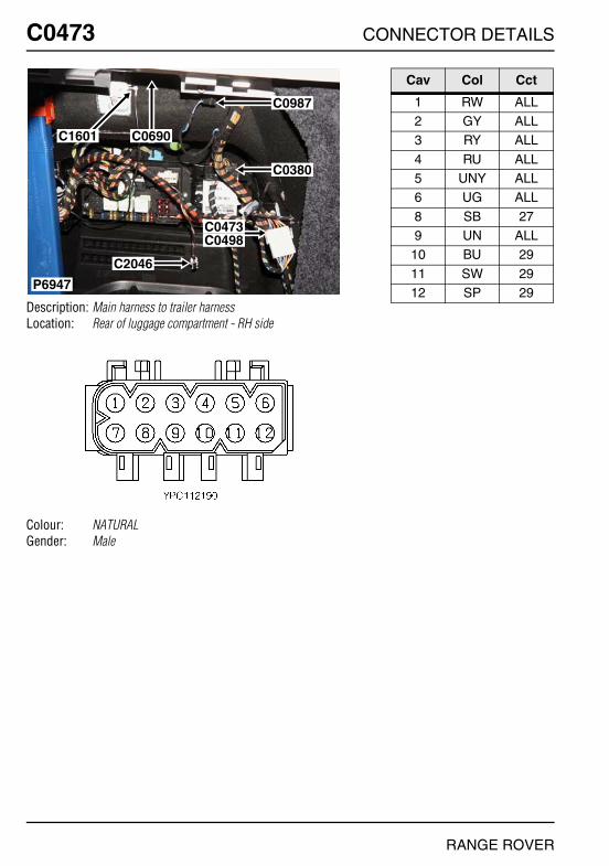
O
C0473 CC0473
Description: Main harness to trailer harnessLocation: Rear of luggage compartment - RH side
Colour: NATURALGender: Male
P6947
C0987
C0380
C0473C0498
C2046
C0690C1601
NNECTOR DETAILS
Cav Col Cct
1 RW ALL2 GY ALL3 RY ALL
4 RU ALL5 UNY ALL6 UG ALL
8 SB 279 UN ALL
10 BU 29
11 SW 2912 SP 29
RANGE ROVER
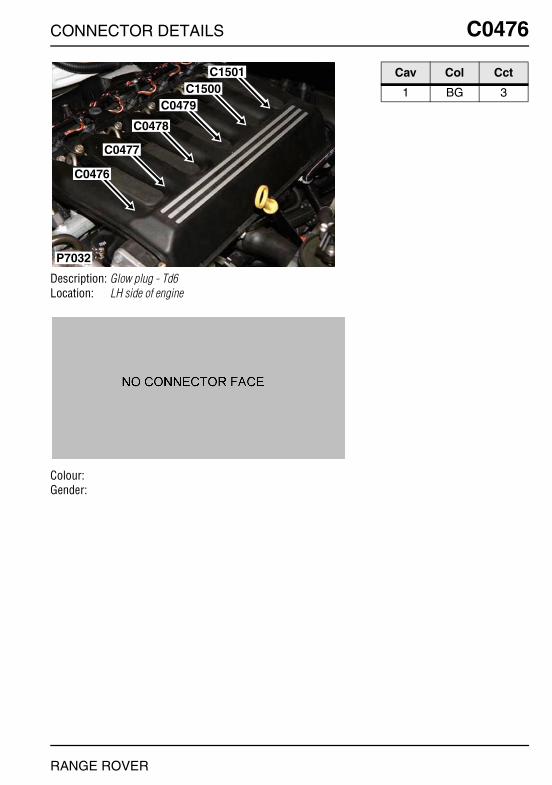
CONNECTOR DETAILS
C0476
Description: Glow plug - Td6Location: LH side of engine
Colour:Gender:
C1501C1500
C0479
C0478
C0477
C0476
P7032
RANGE ROVER
C0476
Cav Col Cct
1 BG 3

O
C0477 CC0477
Description: Glow plug - Td6Location: LH side of engine
Colour:Gender:
C1501C1500
C0479
C0478
C0477
C0476
P7032
NNECTOR DETAILS
Cav Col Cct
1 BP 3
RANGE ROVER

CONNECTOR DETAILS
C0478
Description: Glow plug - Td6Location: LH side of engine
Colour:Gender:
C1501C1500
C0479
C0478
C0477
C0476
P7032
RANGE ROVER
C0478
Cav Col Cct
1 BY 3

O
C0479 CC0479
Description: Glow plug - Td6Location: LH side of engine
Colour:Gender:
C1501C1500
C0479
C0478
C0477
C0476
P7032
NNECTOR DETAILS
Cav Col Cct
1 BR 3
RANGE ROVER

CONNECTOR DETAILS
C0502
Description: Sensor-ABS-Rear-LHLocation: Below LH rear wheelarch
Colour: BLUEGender: Female
P7009
C2028 C0502
RANGE ROVER
C0502
Cav Col Cct
1 W ALL2 UW ALL
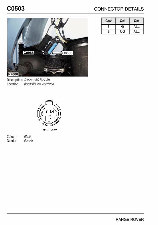
O
C0503 CC0503
Description: Sensor-ABS-Rear-RHLocation: Below RH rear wheelarch
Colour: BLUEGender: Female
P7006
C0968 C0503
NNECTOR DETAILS
Cav Col Cct
1 G ALL2 UG ALL
RANGE ROVER

CONNECTOR DETAILS
C0506
Description: ECU-ABSLocation: Rear LH side of engine compartment
Colour:Gender:
P6879
C0506
C2036
RANGE ROVER
C0506
Cav Col Cct
1 N ALL2 R ALL3 BG ALL
4 BN ALL5 N ALL6 RB ALL
7 YN ALL8 NBY ALL9 WRY ALL
10 WUY ALL11 WP ALL12 R ALL
13 UW ALL14 UG ALL15 UY ALL
16 Y ALL17 BG ALL18 YW 22
19 YG ALL20 SB ALL21 UWY ALL
23 RW ALL24 YB 125 WU ALL
26 UB ALL27 BY ALL28 UR ALL
29 W ALL31 G ALL32 UR ALL
34 NR ALL35 YR 1536 NGY ALL
39 WSY ALL40 YN 141 BRY ALL
42 BP ALL

O
C0507 CC0507
Description: Pump-Return-ABSLocation: Rear of engine compartment
Colour: BLACKGender: Female
P6884
C0666
C0507
C0026
C0030
C0007
NNECTOR DETAILS
Cav Col Cct
1 BN ALL2 BG ALL
RANGE ROVER
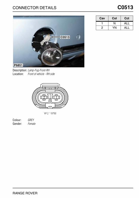
CONNECTOR DETAILS
C0513
Description: Lamp-Fog-Front-RHLocation: Front of vehicle - RH side
Colour: GREYGender: Female
P6851
C0513
RANGE ROVER
C0513
Cav Col Cct
1 N ALL2 YN ALL
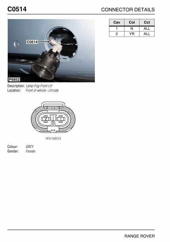
O
C0514 CC0514
Description: Lamp-Fog-Front-LHLocation: Front of vehicle - LH side
Colour: GREYGender: Female
P6852
C0514
NNECTOR DETAILS
Cav Col Cct
1 N ALL2 YR ALL
RANGE ROVER

CONNECTOR DETAILS
C0516
Description: Sensor-ABS-Front-LHLocation: Behind LH front wheel arch liner
Colour: BLUEGender: Female
P6877
C0516
C0050
RANGE ROVER
C0516
Cav Col Cct
1 R ALL2 UR ALL

O
C0517 CC0517
Description: Sensor-ABS-Front-RHLocation: Behind RH front wheel arch liner
Colour: BLUEGender: Female
P6874
C0517
NNECTOR DETAILS
Cav Col Cct
1 Y ALL2 UY ALL
RANGE ROVER
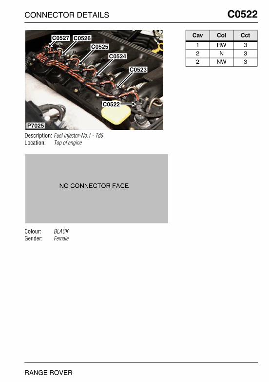
CONNECTOR DETAILS
C0522
Description: Fuel injector-No.1 - Td6Location: Top of engine
Colour: BLACKGender: Female
C0526
C0524
C0523
C0525
P7025
C0527
C0522
RANGE ROVER
C0522
Cav Col Cct
1 RW 32 N 32 NW 3

O
C0523 CC0523
Description: Fuel injector-No.2 - Td6Location: Top of engine
Colour: BLACKGender: Female
C0526
C0524
C0523
C0525
P7025
C0527
C0522
NNECTOR DETAILS
Cav Col Cct
1 RW 32 N 32 NY 3
RANGE ROVER

CONNECTOR DETAILS
C0524
Description: Fuel injector-No.3 - Td6Location: Top of engine
Colour: BLACKGender: Female
C0526
C0524
C0523
C0525
P7025
C0527
C0522
RANGE ROVER
C0524
Cav Col Cct
1 RW 32 NG 32 N 3
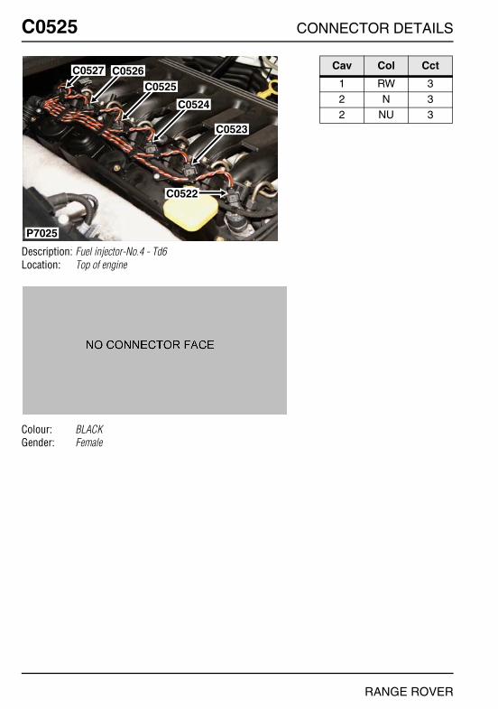
O
C0525 CC0525
Description: Fuel injector-No.4 - Td6Location: Top of engine
Colour: BLACKGender: Female
C0526
C0524
C0523
C0525
P7025
C0527
C0522
NNECTOR DETAILS
Cav Col Cct
1 RW 32 N 32 NU 3
RANGE ROVER

CONNECTOR DETAILS
C0526
Description: Fuel injector-No.5 - Td6Location: Top of engine
Colour: BLACKGender: Female
C0526
C0524
C0523
C0525
P7025
C0527
C0522
RANGE ROVER
C0526
Cav Col Cct
1 RW 32 O 32 N 3

O
C0527 CC0527
Description: Fuel injector-No.6Location: Top of engine
Colour: BLACKGender: Female
C0526
C0524
C0523
C0525
P7025
C0527
C0522
NNECTOR DETAILS
Cav Col Cct
1 RW 32 N 12 NS 2
RANGE ROVER
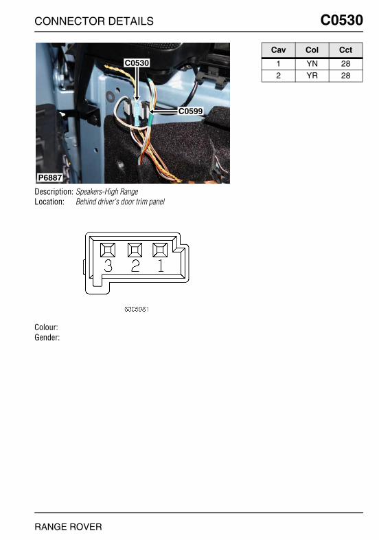
CONNECTOR DETAILS
C0530
Description: Speakers-High RangeLocation: Behind driver's door trim panel
Colour:Gender:
P6887
C0530
C0599
RANGE ROVER
C0530
Cav Col Cct
1 YN 282 YR 28
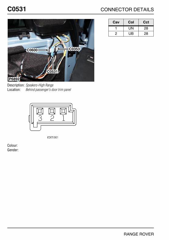
O
C0531 CC0531
Description: Speakers-High RangeLocation: Behind passenger's door trim panel
Colour:Gender:
P6892
C0531
C0353C0600
NNECTOR DETAILS
Cav Col Cct
1 UN 282 UB 28
RANGE ROVER

CONNECTOR DETAILS
C0537
Description: Lamp-Side-Front-RHLocation: Behind RH side of front bumper
Colour:Gender:
P6863
C0002
C0537
RANGE ROVER
C0537
Cav Col Cct
1 N ALL2 SU ALL

O
C0538 CC0538
Description: Lamp-Side-Front-LHLocation: Behind LH side of front bumper
Colour:Gender:
P6853
C0001
C0538
NNECTOR DETAILS
Cav Col Cct
1 N ALL2 SG ALL
RANGE ROVER

CONNECTOR DETAILS
C0546
Description: ECU-Delay-Windscreen wiperLocation: Rear LH side of engine compartment
Colour: BLACKGender: Female
P6886
C1319
C0546
C1455
C1854
C1855
RANGE ROVER
C0546
Cav Col Cct
1 NU ALL2 RW ALL3 NW ALL
4 BG ALL5 N ALL6 BN ALL

O
C0550 CC0550
Description: EarthLocation: Front RH side of engine compartment
Colour: TIN-PLATEGender: Male
P6867
C0018
C0550
NNECTOR DETAILS
Cav Col Cct
0 N ALL
RANGE ROVER
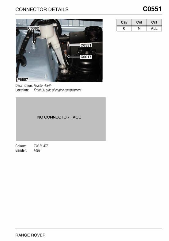
CONNECTOR DETAILS
C0551
Description: Header -EarthLocation: Front LH side of engine compartment
Colour: TIN-PLATEGender: Male
P6857
C0362
C0551
C0017
RANGE ROVER
C0551
Cav Col Cct
0 N ALL

O
C0552 CC0552
Description: Header -EarthLocation: Base of RH 'A' post
Colour: TIN-PLATEGender: Male
P6974
C0552
NNECTOR DETAILS
Cav Col Cct
0 NB ALL
RANGE ROVER

CONNECTOR DETAILS
C0553
Description: Header -EarthLocation: Beneath LH seat
Colour: TIN-PLATEGender: Male
P7000
C0553
RANGE ROVER
C0553
Cav Col Cct
0 N ALL
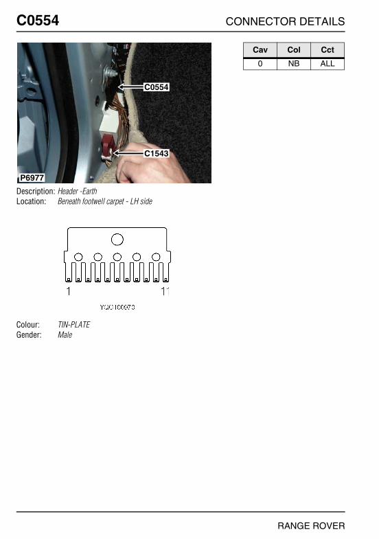
O
C0554 CC0554
Description: Header -EarthLocation: Beneath footwell carpet - LH side
Colour: TIN-PLATEGender: Male
P6977
C0554
C1543
NNECTOR DETAILS
Cav Col Cct
0 NB ALL
RANGE ROVER
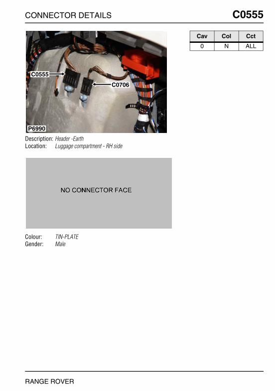
CONNECTOR DETAILS
C0555
Description: Header -EarthLocation: Luggage compartment - RH side
Colour: TIN-PLATEGender: Male
P6990
C0555
C0706
RANGE ROVER
C0555
Cav Col Cct
0 N ALL

O
C0556 CC0556
Description: EarthLocation: Front LH side of engine compartment
Colour: TIN-PLATEGender: Eyelet
P6855
C0556
C0187
NNECTOR DETAILS
Cav Col Cct
1 NB 2
RANGE ROVER

CONNECTOR DETAILS
C0559
Description: EarthLocation: RH side of engine compartment
Colour: TIN-PLATEGender: Eyelet
P7024
C0559
C0629
RANGE ROVER
C0559
Cav Col Cct
1 NO 3
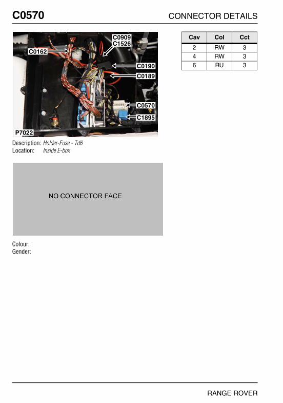
O
C0570 CC0570
Description: Holder-Fuse - Td6Location: Inside E-box
Colour:Gender:
P7022
C0162
C0909C1526
C0190
C0189
C0570
C1895
NNECTOR DETAILS
Cav Col Cct
2 RW 34 RW 36 RU 3
RANGE ROVER
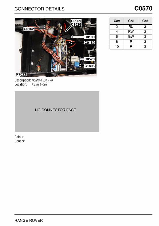
CONNECTOR DETAILS
C0570
Description: Holder-Fuse - V8Location: Inside E-box
Colour:Gender:
P7022
C0162
C0909C1526
C0190
C0189
C0570
C1895
RANGE ROVER
C0570
Cav Col Cct
2 RU 34 RW 36 GW 3
8 R 310 R 3
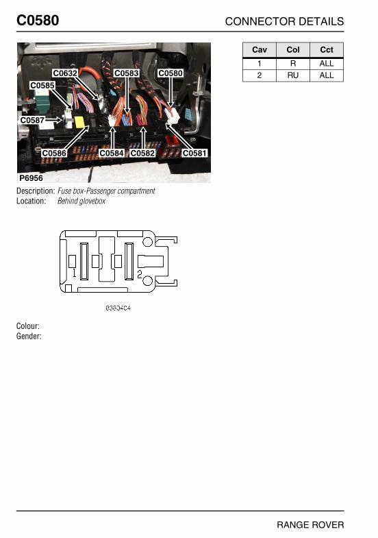
O
C0580 CC0580
Description: Fuse box-Passenger compartmentLocation: Behind glovebox
Colour:Gender:
P6956
C0583 C0580C0632
C0585
C0587
C0586 C0581C0582C0584
NNECTOR DETAILS
Cav Col Cct
1 R ALL2 RU ALL
RANGE ROVER
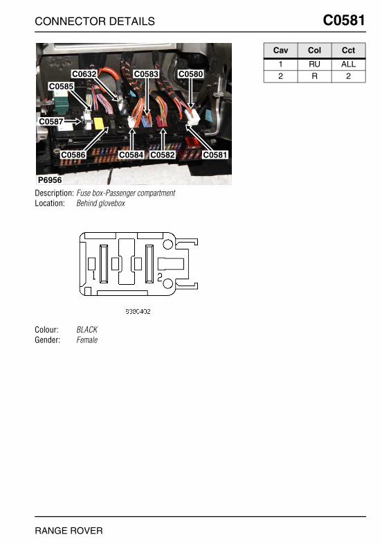
CONNECTOR DETAILS
C0581
Description: Fuse box-Passenger compartmentLocation: Behind glovebox
Colour: BLACKGender: Female
P6956
C0583 C0580C0632
C0585
C0587
C0586 C0581C0582C0584
RANGE ROVER
C0581
Cav Col Cct
1 RU ALL2 R 2
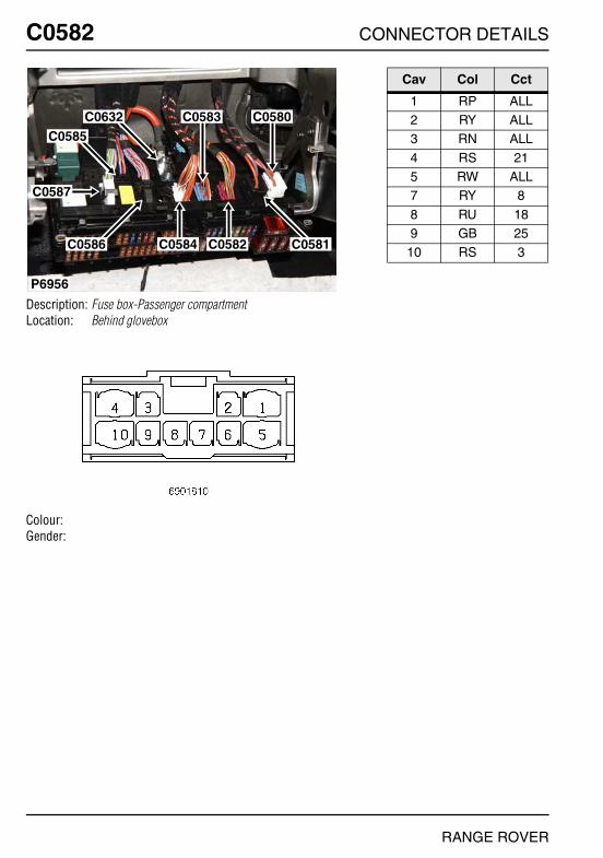
O
C0582 CC0582
Description: Fuse box-Passenger compartmentLocation: Behind glovebox
Colour:Gender:
P6956
C0583 C0580C0632
C0585
C0587
C0586 C0581C0582C0584
NNECTOR DETAILS
Cav Col Cct
1 RP ALL2 RY ALL3 RN ALL
4 RS 215 RW ALL7 RY 8
8 RU 189 GB 25
10 RS 3
RANGE ROVER
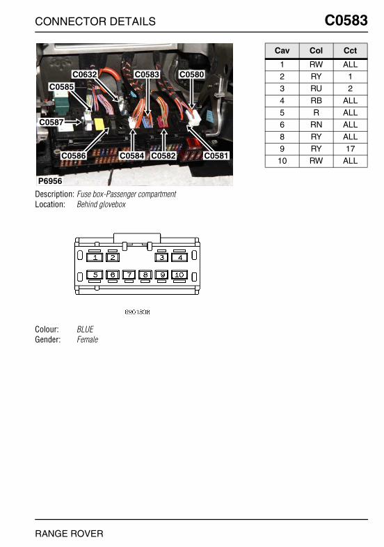
CONNECTOR DETAILS
C0583
Description: Fuse box-Passenger compartmentLocation: Behind glovebox
Colour: BLUEGender: Female
P6956
C0583 C0580C0632
C0585
C0587
C0586 C0581C0582C0584
RANGE ROVER
C0583
Cav Col Cct
1 RW ALL2 RY 13 RU 2
4 RB ALL5 R ALL6 RN ALL
8 RY ALL9 RY 17
10 RW ALL
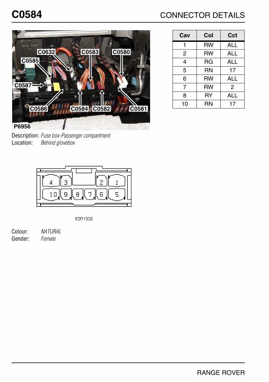
O
C0584 CC0584
Description: Fuse box-Passenger compartmentLocation: Behind glovebox
Colour: NATURALGender: Female
P6956
C0583 C0580C0632
C0585
C0587
C0586 C0581C0582C0584
NNECTOR DETAILS
Cav Col Cct
1 RW ALL2 RW ALL4 RG ALL
5 RN 176 RW ALL7 RW 2
8 RY ALL10 RN 17
RANGE ROVER

CONNECTOR DETAILS
C0585
Description: Fuse box-Passenger compartmentLocation: Behind glovebox
Colour: BLACKGender: Female
P6956
C0583 C0580C0632
C0585
C0587
C0586 C0581C0582C0584
RANGE ROVER
C0585
Cav Col Cct
1 RP ALL2 RW ALL3 PS ALL
4 BG ALL5 PB ALL6 GR 22
7 RU ALL8 N ALL9 PS ALL
10 G ALL
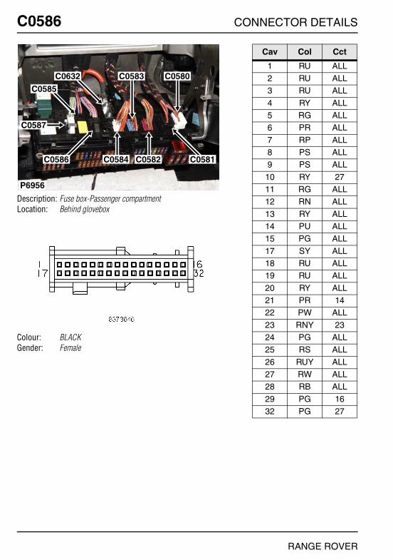
O
C0586 CC0586
Description: Fuse box-Passenger compartmentLocation: Behind glovebox
Colour: BLACKGender: Female
P6956
C0583 C0580C0632
C0585
C0587
C0586 C0581C0582C0584
NNECTOR DETAILS
Cav Col Cct
1 RU ALL2 RU ALL3 RU ALL
4 RY ALL5 RG ALL6 PR ALL
7 RP ALL8 PS ALL9 PS ALL
10 RY 2711 RG ALL12 RN ALL
13 RY ALL14 PU ALL15 PG ALL
17 SY ALL18 RU ALL19 RU ALL
20 RY ALL21 PR 1422 PW ALL
23 RNY 2324 PG ALL25 RS ALL
26 RUY ALL27 RW ALL28 RB ALL
29 PG 1632 PG 27
RANGE ROVER
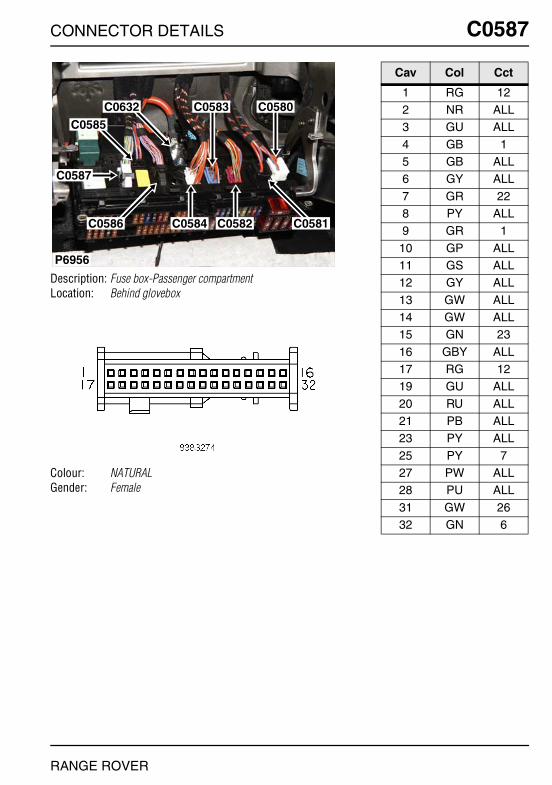
CONNECTOR DETAILS
C0587
Description: Fuse box-Passenger compartmentLocation: Behind glovebox
Colour: NATURALGender: Female
P6956
C0583 C0580C0632
C0585
C0587
C0586 C0581C0582C0584
RANGE ROVER
C0587
Cav Col Cct
1 RG 122 NR ALL3 GU ALL
4 GB 15 GB ALL6 GY ALL
7 GR 228 PY ALL9 GR 1
10 GP ALL11 GS ALL12 GY ALL
13 GW ALL14 GW ALL15 GN 23
16 GBY ALL17 RG 1219 GU ALL
20 RU ALL21 PB ALL23 PY ALL
25 PY 727 PW ALL28 PU ALL
31 GW 2632 GN 6
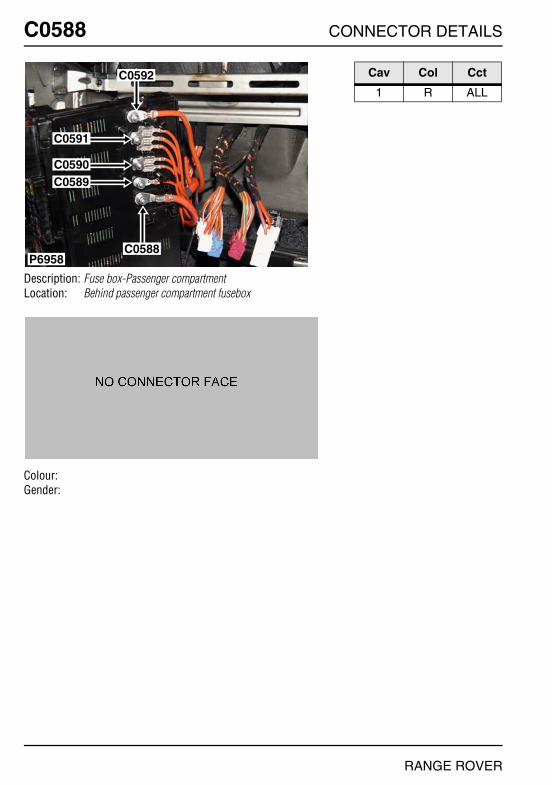
O
C0588 CC0588
Description: Fuse box-Passenger compartmentLocation: Behind passenger compartment fusebox
Colour:Gender:
C0592
C0588
C0591
C0590C0589
P6958
NNECTOR DETAILS
Cav Col Cct
1 R ALL
RANGE ROVER

CONNECTOR DETAILS
C0589
Description: Fuse box-Passenger compartmentLocation: Behind passenger compartment fusebox
Colour:Gender:
C0592
C0588
C0591
C0590C0589
P6958
RANGE ROVER
C0589
Cav Col Cct
0 R ALL

O
C0590 CC0590
Description: Fuse box-Passenger compartmentLocation: Behind passenger compartment fusebox
Colour:Gender:
C0592
C0588
C0591
C0590C0589
P6958
NNECTOR DETAILS
Cav Col Cct
1 R ALL
RANGE ROVER
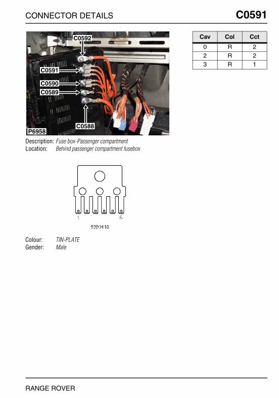
CONNECTOR DETAILS
C0591
Description: Fuse box-Passenger compartmentLocation: Behind passenger compartment fusebox
Colour: TIN-PLATEGender: Male
C0592
C0588
C0591
C0590C0589
P6958
RANGE ROVER
C0591
Cav Col Cct
0 R 22 R 23 R 1

O
C0592 CC0592
Description: Fuse box-Passenger compartmentLocation: Behind passenger compartment fusebox
Colour:Gender:
C0592
C0588
C0591
C0590C0589
P6958
NNECTOR DETAILS
Cav Col Cct
1 R 9
RANGE ROVER

CONNECTOR DETAILS
C0599
Description: Sensor-Anti-trap-DriverLocation: Behind driver's door trim panel
Colour:Gender:
P6887
C0530
C0599
RANGE ROVER
C0599
Cav Col Cct
1 N 32 NR 3

O
C0600 CC0600
Description: Sensor-Anti-trap-PassengerLocation: Behind passenger's door trim panel
Colour:Gender:
P6892
C0531
C0353C0600
NNECTOR DETAILS
Cav Col Cct
1 N 32 NR 3
RANGE ROVER
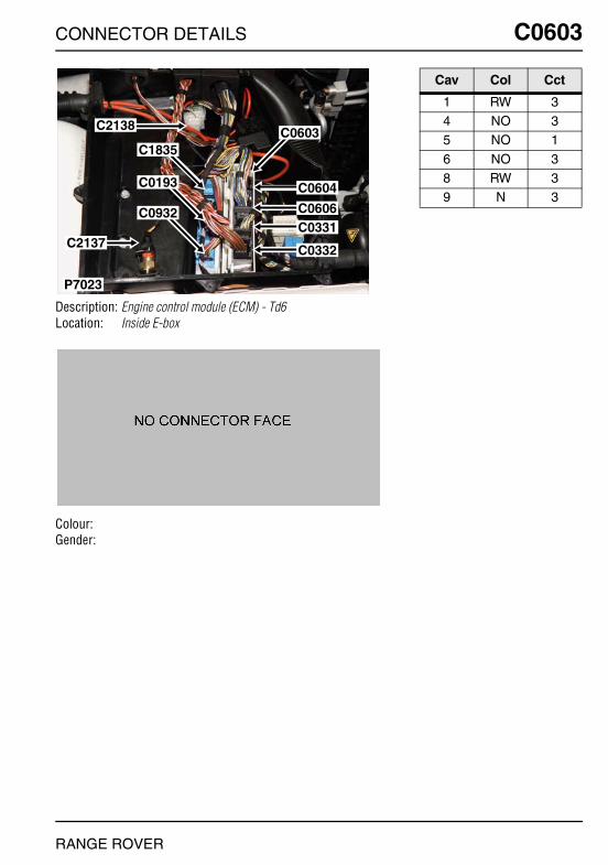
CONNECTOR DETAILS
C0603
Description: Engine control module (ECM) - Td6Location: Inside E-box
Colour:Gender:
P7023
C0604
C0603C2138
C1835
C0193
C0932
C2137
C0606C0331
C0332
RANGE ROVER
C0603
Cav Col Cct
1 RW 34 NO 35 NO 1
6 NO 38 RW 39 N 3

O
C0603 CC0603
Description: Engine control module (ECM) - V8Location: Inside E-box
Colour:Gender:
P7039
C0604
C0603
C0606
C0332
C0331
NNECTOR DETAILS
Cav Col Cct
4 N 35 N 36 N 3
7 R 38 RU 3
RANGE ROVER

CONNECTOR DETAILS
C0604
Description: Engine control module (ECM) - Td6Location: Inside E-box
Colour:Gender:
P7023
C0604
C0603C2138
C1835
C0193
C0932
C2137
C0606C0331
C0332
RANGE ROVER
C0604
Cav Col Cct
3 YN 34 YB 36 WPY 3
8 NP 39 Y 8
10 WN 3
17 BW 2
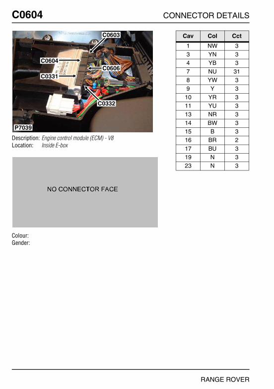
O
C0604 CC0604
Description: Engine control module (ECM) - V8Location: Inside E-box
Colour:Gender:
P7039
C0604
C0603
C0606
C0332
C0331
NNECTOR DETAILS
Cav Col Cct
1 NW 33 YN 34 YB 3
7 NU 318 YW 39 Y 3
10 YR 311 YU 313 NR 3
14 BW 315 B 316 BR 2
17 BU 319 N 323 N 3
RANGE ROVER
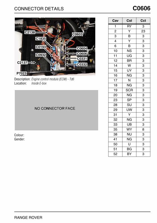
CONNECTOR DETAILS
C0606
Description: Engine control module (ECM) - Td6Location: Inside E-box
Colour:Gender:
P7023
C0604
C0603C2138
C1835
C0193
C0932
C2137
C0606C0331
C0332
RANGE ROVER
C0606
Cav Col Cct
1 RY 32 Y 233 B 3
4 Y 36 B 3
10 NS 3
11 UG 312 BR 314 W 3
15 UY 316 NG 317 N 3
18 NG 319 SCR 320 NG 3
23 SP 328 SU 329 UW 3
31 Y 332 NG 333 UB 3
35 WY 838 NU 341 NG 3
50 U 351 BG 352 BY 3
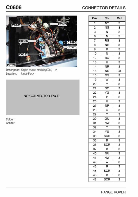
O
C0606 CC0606
Description: Engine control module (ECM) - V8Location: Inside E-box
Colour:Gender:
P7020
C0162
C0606
C0332
C2089
C1895
C0570
NNECTOR DETAILS
Cav Col Cct
1 NY 32 NG 33 N 3
6 N 37 RG 38 NR 8
9 B 310 N 312 BG 3
13 U 314 NR 315 NS 23
16 GS 319 W 320 Y 8
21 NO 322 YG 324 P 3
25 U 227 NP 328 O 3
29 Y 329 GU 331 NW 3
32 Y 334 YU 335 SCR 3
36 B 336 SCR 337 B 3
40 NU 341 NW 342 w 3
43 R 345 SCR 346 B 3
48 SCR 3
RANGE ROVER
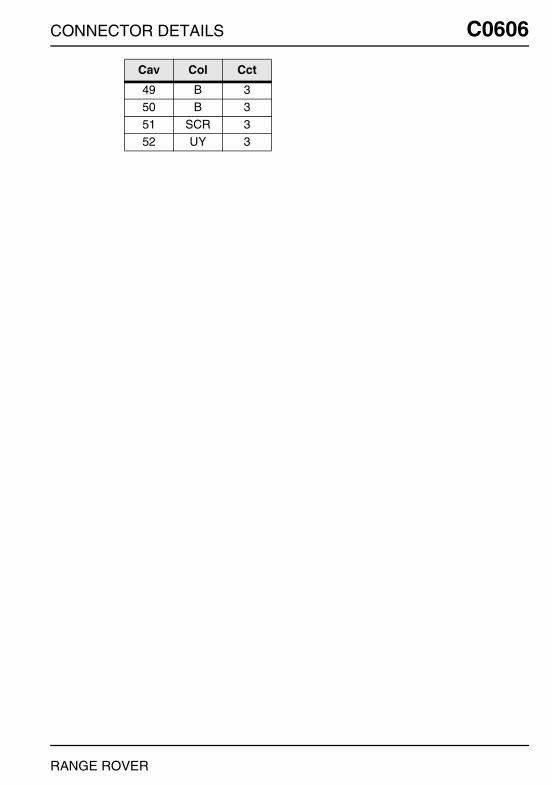
CONNECTOR DETAILS
49 B 350 B 3
51 SCR 352 UY 3
Cav Col Cct
RANGE ROVER
C0606
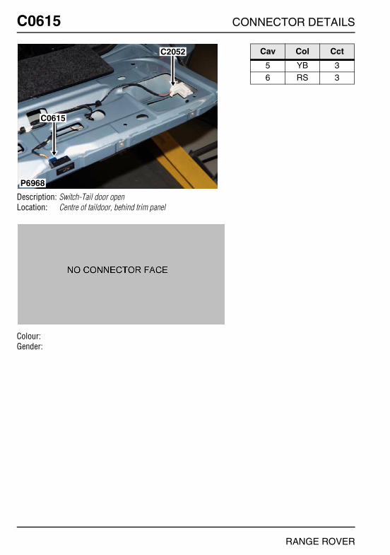
O
C0615 CC0615
Description: Switch-Tail door openLocation: Centre of taildoor, behind trim panel
Colour:Gender:
P6968
C2052
C0615
NNECTOR DETAILS
Cav Col Cct
5 YB 36 RS 3
RANGE ROVER

CONNECTOR DETAILS
C0617
Description: Motor-Lock-Tail doorLocation: LH side of taildoor
Colour:Gender:
P6969
C0617
RANGE ROVER
C0617
Cav Col Cct
1 N 32 UW 3

O
C0620 CC0620
Description: Sensor-Low washer fluid levelLocation: Front LH side of engine compartment
Colour: BLACKGender: Female
P6858
C0021
C1342C0008
C0620
NNECTOR DETAILS
Cav Col Cct
1 NB ALL2 NG ALL
RANGE ROVER
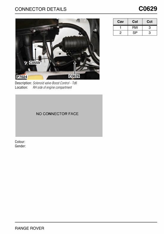
CONNECTOR DETAILS
C0629
Description: Solenoid valve-Boost Control - Td6Location: RH side of engine compartment
Colour:Gender:
P7024
C0559
C0629
RANGE ROVER
C0629
Cav Col Cct
1 RW 32 SP 3

O
C0642 CC0642
Description: Sensor-Heated oxygen (HO2S)Location: Beneath centre of vehicle
Colour:Gender:
P6940
C0642
NNECTOR DETAILS
Cav Col Cct
1 G 32 NW 33 YW 3
4 BW 3
RANGE ROVER

CONNECTOR DETAILS
C0643
Description: Sensor-Heated oxygen (HO2S)Location: Beneath centre of vehicle
Colour:Gender:
P6941
C0643
C1858
RANGE ROVER
C0643
Cav Col Cct
1 G 32 NU 313 YU 3
4 BU 3
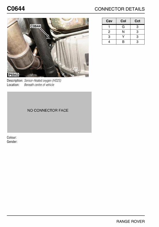
O
C0644 CC0644
Description: Sensor-Heated oxygen (HO2S)Location: Beneath centre of vehicle
Colour:Gender:
C0644
P6943
NNECTOR DETAILS
Cav Col Cct
1 G 32 N 33 Y 3
4 B 3
RANGE ROVER
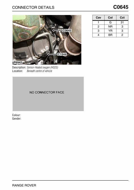
CONNECTOR DETAILS
C0645
Description: Sensor-Heated oxygen (HO2S)Location: Beneath centre of vehicle
Colour:Gender:
P6942
C0645
C1544
RANGE ROVER
C0645
Cav Col Cct
1 G 312 NR 33 YR 3
4 BR 2

O
C0646 CC0646
Description: Fan-E-boxLocation: Inside E-box
Colour: NATURALGender: Female
P6882
C0448
C2138
C0193
C0331
C1886
C0646
C2137
NNECTOR DETAILS
Cav Col Cct
1 R 2
RANGE ROVER
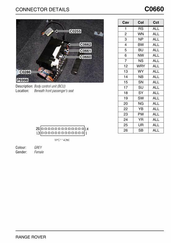
CONNECTOR DETAILS
C0660
Description: Body control unit (BCU)Location: Beneath front passenger's seat
Colour: GREYGender: Female
P6998
C0662
C0661
C0660
C0286
C0255
RANGE ROVER
C0660
Cav Col Cct
1 RS ALL2 WN ALL3 NP ALL
4 BW ALL5 BU ALL6 NW ALL
7 NS ALL12 WRY ALL13 WY ALL
14 NB ALL15 SN ALL17 SU ALL
18 SY ALL19 SW ALL20 NG ALL
22 YB ALL23 PW ALL24 YR ALL
25 UR ALL26 SB ALL

O
C0661 CC0661
Description: Body control unit (BCU)Location: Beneath front passenger's seat
Colour: GREYGender: Female
P6998
C0662
C0661
C0660
C0286
C0255
NNECTOR DETAILS
Cav Col Cct
2 PG ALL4 UY 235 BY ALL
8 BU ALL10 SY ALL11 SN ALL
12 NY ALL13 SU ALL15 NU ALL
16 NW ALL17 UB 2119 SBY ALL
20 BS ALL22 NY ALL23 NR ALL
24 NR ALL25 BG ALL26 NB ALL
RANGE ROVER

CONNECTOR DETAILS
C0662
Description: Body control unit (BCU)Location: Beneath front passenger's seat
Colour: BLACKGender: Female
P6998
C0662
C0661
C0660
C0286
C0255
RANGE ROVER
C0662
Cav Col Cct
1 N ALL2 US ALL3 YN ALL
4 RW ALL5 UP ALL6 B ALL
9 BW ALL10 RP ALL11 BR ALL
12 BG ALL13 W ALL14 U ALL
15 BN ALL17 BU ALL18 B ALL
19 RY ALL20 RU ALL
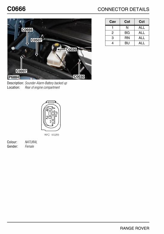
O
C0666 CC0666
Description: Sounder-Alarm-Battery backed upLocation: Rear of engine compartment
Colour: NATURALGender: Female
P6884
C0666
C0507
C0026
C0030
C0007
NNECTOR DETAILS
Cav Col Cct
1 N ALL2 BG ALL3 RN ALL
4 BU ALL
RANGE ROVER

CONNECTOR DETAILS
C0672
Description: Sensor-Key inLocation: Beneath centre console
Colour: BLACKGender: Female
P6913
C0049C0672
C0028C0099
C0673
RANGE ROVER
C0672
Cav Col Cct
1 B 12 S 13 U 1
4 NB 1
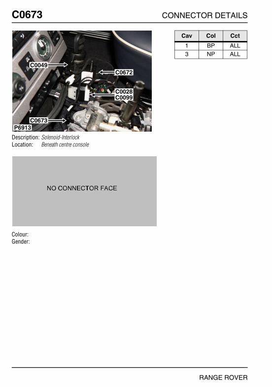
O
C0673 CC0673
Description: Solenoid-InterlockLocation: Beneath centre console
Colour:Gender:
P6913
C0049C0672
C0028C0099
C0673
NNECTOR DETAILS
Cav Col Cct
1 BP ALL3 NP ALL
RANGE ROVER
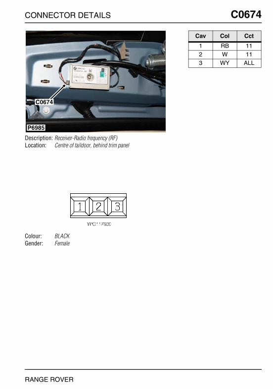
CONNECTOR DETAILS
C0674
Description: Receiver-Radio frequency (RF)Location: Centre of taildoor, behind trim panel
Colour: BLACKGender: Female
P6985
C0674
RANGE ROVER
C0674
Cav Col Cct
1 RB 112 W 113 WY ALL
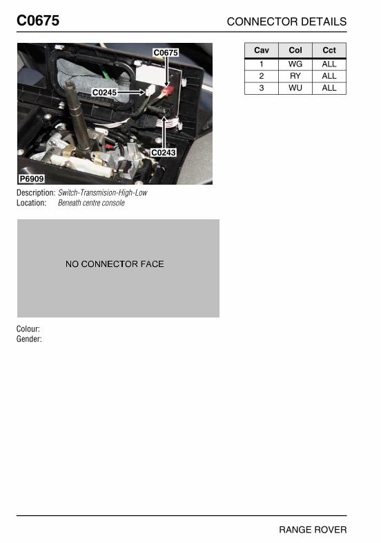
O
C0675 CC0675
Description: Switch-Transmision-High-LowLocation: Beneath centre console
Colour:Gender:
P6909
C0675
C0245
C0243
NNECTOR DETAILS
Cav Col Cct
1 WG ALL2 RY ALL3 WU ALL
RANGE ROVER
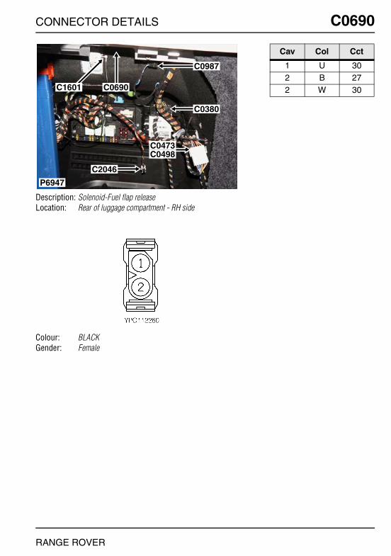
CONNECTOR DETAILS
C0690
Description: Solenoid-Fuel flap releaseLocation: Rear of luggage compartment - RH side
Colour: BLACKGender: Female
P6947
C0987
C0380
C0473C0498
C2046
C0690C1601
RANGE ROVER
C0690
Cav Col Cct
1 U 302 B 272 W 30

O
C0698 CC0698
Description: Mirror-interiorLocation: Top of windscreen
Colour:Gender:
P6934
C0961
C0698
NNECTOR DETAILS
Cav Col Cct
1 UY 262 WY 103 GW 26
4 WU 265 WR 266 WY 26
7 WG 268 RY ALL9 SBY ALL
10 NB 26
RANGE ROVER

CONNECTOR DETAILS
C0700
Description: Switch pack-Centre consoleLocation: Behind centre console
Colour: GREYGender: Female
P6926C0232 C0700
C1629
C1630
C0249
RANGE ROVER
C0700
Cav Col Cct
2 SN ALL4 YW ALL5 SR ALL
6 UP ALL7 BY ALL
11 SR ALL
12 NUY 614 UR 2315 GBY ALL
17 SU ALL18 SP ALL19 SY ALL
20 SG ALL21 WY ALL22 NWY 6
25 UN 2326 N ALL
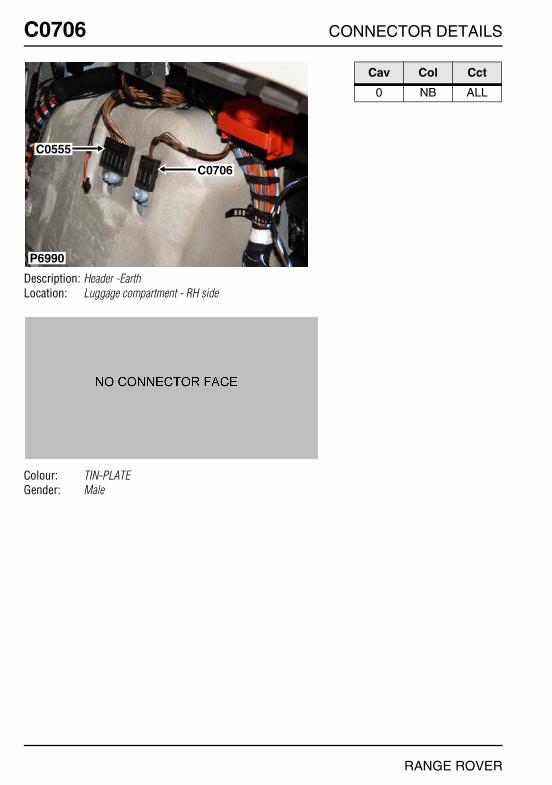
O
C0706 CC0706
Description: Header -EarthLocation: Luggage compartment - RH side
Colour: TIN-PLATEGender: Male
P6990
C0555
C0706
NNECTOR DETAILS
Cav Col Cct
0 NB ALL
RANGE ROVER
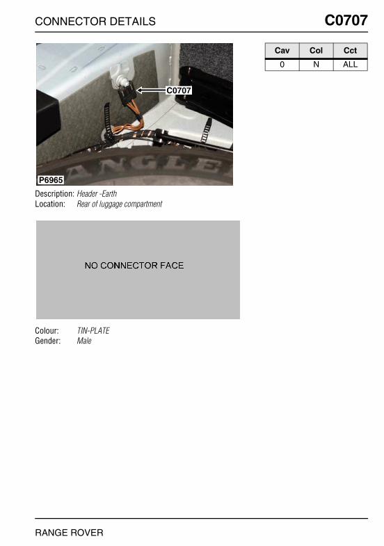
CONNECTOR DETAILS
C0707
Description: Header -EarthLocation: Rear of luggage compartment
Colour: TIN-PLATEGender: Male
P6965
C0707
RANGE ROVER
C0707
Cav Col Cct
0 N ALL
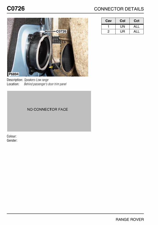
O
C0726 CC0726
Description: Speakers-Low rangeLocation: Behind passenger's door trim panel
Colour:Gender:
P6894
C0726
NNECTOR DETAILS
Cav Col Cct
1 UN ALL2 UR ALL
RANGE ROVER

CONNECTOR DETAILS
C0732
Description: Switch-Window-RearLocation: Behind rear door trim panel
Colour: BLACKGender: Female
P6903
C0732C2015
C0311
RANGE ROVER
C0732
Cav Col Cct
1 SN 32 N 33 SR 3
4 SB 3

O
C0736 CC0736
Description: Mirror-Vanity-RHLocation: Headlining - front RH side
Colour: BLACKGender: Female
P6937
C0736
NNECTOR DETAILS
Cav Col Cct
1 NB ALL3 PS ALL
RANGE ROVER

CONNECTOR DETAILS
C0737
Description: Mirror-Vanity-LHLocation: Headlining - front LH side
Colour: BLACKGender: Female
P6936
C0737
RANGE ROVER
C0737
Cav Col Cct
1 NB ALL3 PS ALL
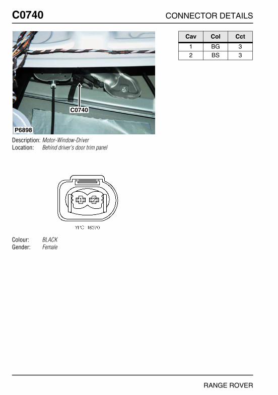
O
C0740 CC0740
Description: Motor-Window-DriverLocation: Behind driver's door trim panel
Colour: BLACKGender: Female
P6898
C0740
NNECTOR DETAILS
Cav Col Cct
1 BG 32 BS 3
RANGE ROVER
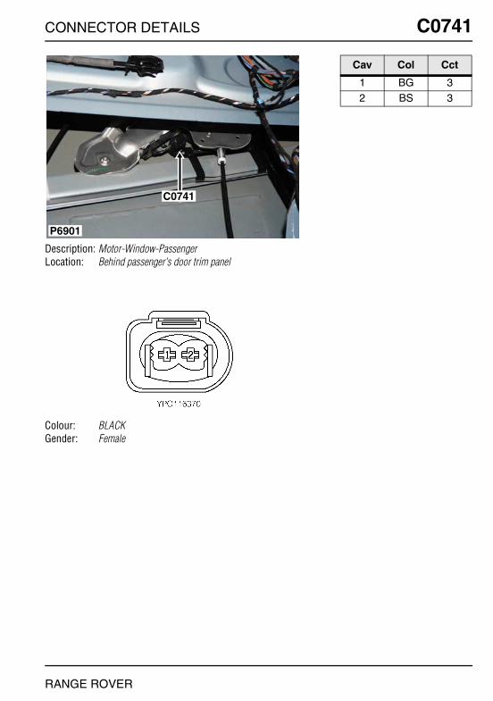
CONNECTOR DETAILS
C0741
Description: Motor-Window-PassengerLocation: Behind passenger's door trim panel
Colour: BLACKGender: Female
P6901
C0741
RANGE ROVER
C0741
Cav Col Cct
1 BG 32 BS 3

O
C0751 CC0751
Description: Seat link harness to main harnessLocation: Beneath front seat
Colour:Gender:
P6992
C0751
NNECTOR DETAILS
Cav Col Cct
13 RN 314 N 215 WRY 3
RANGE ROVER

CONNECTOR DETAILS
C0752
Description: Seat link harness to main harnessLocation: Beneath front seat
Colour:Gender:
C0752
P7001
RANGE ROVER
C0752
Cav Col Cct
13 RN 514 N 315 WRY 3
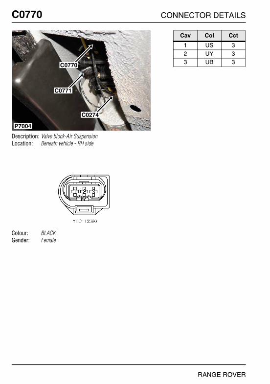
O
C0770 CC0770
Description: Valve block-Air SuspensionLocation: Beneath vehicle - RH side
Colour: BLACKGender: Female
P7004
C0770
C0771
C0274
NNECTOR DETAILS
Cav Col Cct
1 US 32 UY 33 UB 3
RANGE ROVER

CONNECTOR DETAILS
C0771
Description: Valve block-Air SuspensionLocation: Beneath vehicle - RH side
Colour: BLACKGender: Female
P7004
C0770
C0771
C0274
RANGE ROVER
C0771
Cav Col Cct
1 UG 32 UW 3

O
C0784 CC0784
Description: ECU-Sunroof-1Location: Front of headlining in the centre
Colour: BLACKGender: Female
P6933C0784
NNECTOR DETAILS
Cav Col Cct
1 RS 32 N 33 YS 3
9 YG 310 UR 311 SB 3
13 YW 3
RANGE ROVER

CONNECTOR DETAILS
C0786
Description: Main harness to air conditioning (A/C) harnessLocation: Behind centre console
Colour: BLACKGender: Female
P6927
C0277C0786
C0839
RANGE ROVER
C0786
Cav Col Cct
1 N ALL2 RU ALL
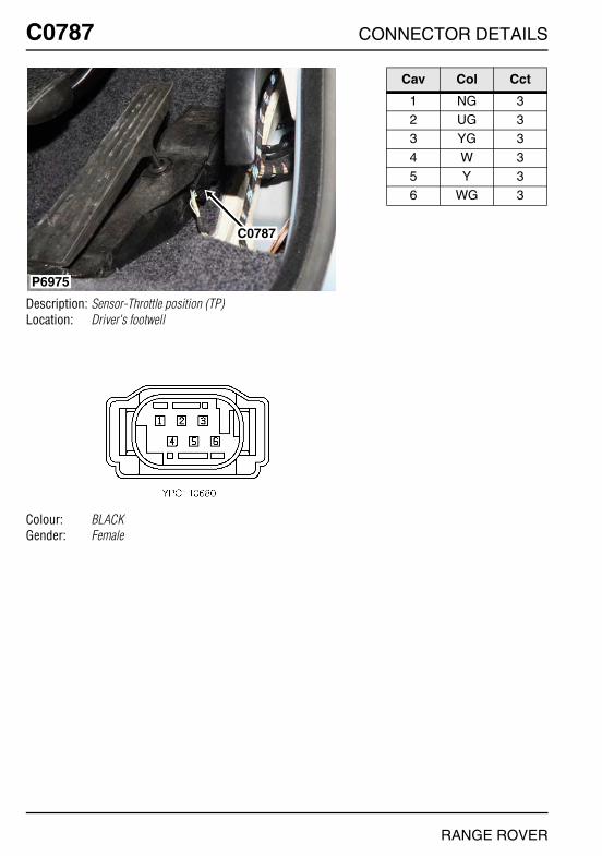
O
C0787 CC0787
Description: Sensor-Throttle position (TP)Location: Driver's footwell
Colour: BLACKGender: Female
P6975
C0787
NNECTOR DETAILS
Cav Col Cct
1 NG 32 UG 33 YG 3
4 W 35 Y 36 WG 3
RANGE ROVER
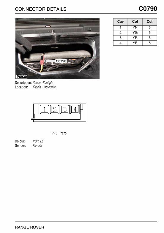
CONNECTOR DETAILS
C0790
Description: Sensor-SunlightLocation: Fascia - top centre
Colour: PURPLEGender: Female
P6930
C0790
RANGE ROVER
C0790
Cav Col Cct
1 YN 52 YG 53 YR 5
4 YB 5
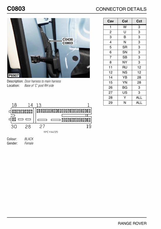
O
C0803 CC0803
Description: Door harness to main harnessLocation: Base of 'C' post RH side
Colour: BLACKGender: Female
P6907
C0803C0436
NNECTOR DETAILS
Cav Col Cct
1 W 32 U 33 B 3
4 N 35 SR 36 SN 3
7 SB 38 NY 3
11 RU 12
12 NS 1214 YB 2815 YN 28
26 BG 327 US 328 Y ALL
29 N ALL
RANGE ROVER

CONNECTOR DETAILS
C0821
Description: Header -EarthLocation: Beneath RH seat
Colour: TIN-PLATEGender: Male
P6995
C0821
RANGE ROVER
C0821
Cav Col Cct
0 N ALL

O
C0823 CC0823
Description: Starter motor - Td6Location: LH side of engine
Colour:Gender:
P7034
C0823C0179
C0178
NNECTOR DETAILS
Cav Col Cct
1 BG 3
RANGE ROVER
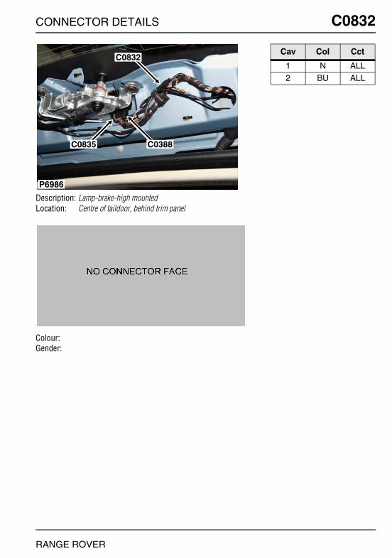
CONNECTOR DETAILS
C0832
Description: Lamp-brake-high mountedLocation: Centre of taildoor, behind trim panel
Colour:Gender:
P6986
C0832
C0835 C0388
RANGE ROVER
C0832
Cav Col Cct
1 N ALL2 BU ALL
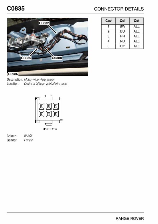
O
C0835 CC0835
Description: Motor-Wiper-Rear screenLocation: Centre of taildoor, behind trim panel
Colour: BLACKGender: Female
P6986
C0832
C0835 C0388
NNECTOR DETAILS
Cav Col Cct
1 BW ALL2 BU ALL3 PR ALL
4 NB ALL6 UY ALL
RANGE ROVER
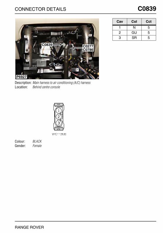
CONNECTOR DETAILS
C0839
Description: Main harness to air conditioning (A/C) harnessLocation: Behind centre console
Colour: BLACKGender: Female
P6927
C0277C0786
C0839
RANGE ROVER
C0839
Cav Col Cct
1 N 52 GU 53 SR 5

O
C0862 CC0862
Description: Sensor-Steering angleLocation: Underside of steering column
Colour: BLACKGender: Male
P6971
C1392C0862
NNECTOR DETAILS
Cav Col Cct
1 RG ALL2 RW ALL3 YB 1
4 YN 15 NB ALL6 WP ALL
RANGE ROVER

CONNECTOR DETAILS
C0867
Description: ECU-Air suspensionLocation: Behind LH side of fascia
Colour:Gender:
C2031
C2030C0867
P6944
RANGE ROVER
C0867
Cav Col Cct
1 YU 22 YB ALL3 SR ALL
4 YW ALL5 SY ALL6 UY ALL
7 UB ALL8 US ALL9 WR ALL
10 WP ALL11 YP ALL12 UG ALL
13 UW ALL14 WG ALL15 WU ALL
16 B ALL17 BU ALL19 YU 2
20 YN ALL21 UP ALL22 SG ALL
23 SP ALL24 BS ALL25 SW ALL
26 YS ALL27 WS ALL28 U ALL
31 BRY ALL32 SB ALL33 BW ALL
34 Y ALL35 BY ALL37 WRY ALL
38 RY ALL39 YG ALL40 WY ALL
41 SU ALL
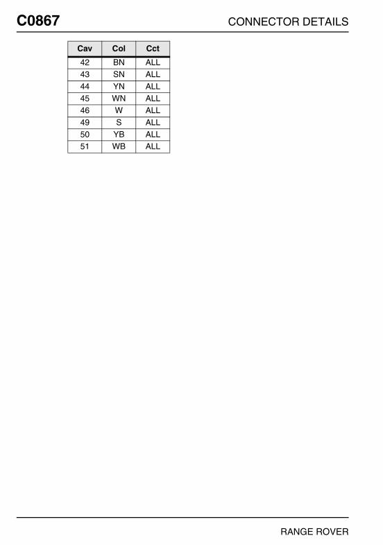
O
C0867 C42 BN ALL43 SN ALL
44 YN ALL45 WN ALL46 W ALL
49 S ALL50 YB ALL51 WB ALL
Cav Col Cct
NNECTOR DETAILS
RANGE ROVER
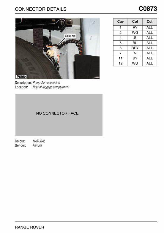
CONNECTOR DETAILS
C0873
Description: Pump-Air suspensionLocation: Rear of luggage compartment
Colour: NATURALGender: Female
C0873
P6964
RANGE ROVER
C0873
Cav Col Cct
1 RY ALL2 WG ALL4 S ALL
5 BU ALL6 BRY ALL7 N ALL
11 BY ALL12 WU ALL
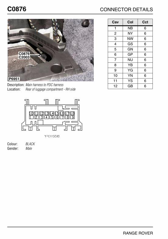
O
C0876 CC0876
Description: Main harness to PDC harnessLocation: Rear of luggage compartment - RH side
Colour: BLACKGender: Male
P6951
C0876C2003
NNECTOR DETAILS
Cav Col Cct
1 NB 62 NY 63 NW 6
4 GS 65 GN 66 GP 6
7 NU 68 YB 69 YG 6
10 YN 611 YS 612 GB 6
RANGE ROVER

CONNECTOR DETAILS
C0879
Description: Pump-Air injectionLocation: Behind RH front wheel arch liner
Colour: BLACKGender: Female
P6869C0879
RANGE ROVER
C0879
Cav Col Cct
1 N 22 BRY 2

O
C0884 CC0884
Description: Sensor-Ambient air temperatureLocation: Behind the front grille
Colour: BLACKGender: Female
P6859
C0884
NNECTOR DETAILS
Cav Col Cct
1 UN ALL2 UR ALL
RANGE ROVER

CONNECTOR DETAILS
C0909
Description: Engine harness to main harness - Td6Location: Inside E-box
Colour:Gender:
P7022
C0162
C0909C1526
C0190
C0189
C0570
C1895
RANGE ROVER
C0909
Cav Col Cct
1 R 32 R 3
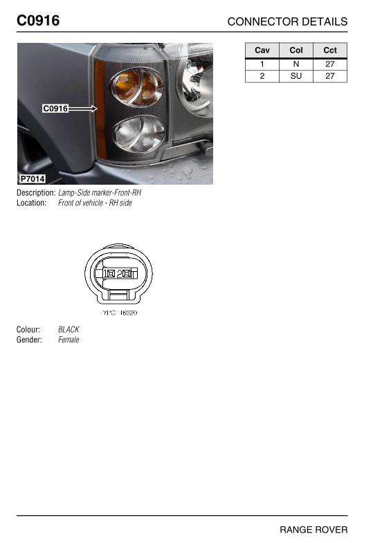
O
C0916 CC0916
Description: Lamp-Side marker-Front-RHLocation: Front of vehicle - RH side
Colour: BLACKGender: Female
P7014
C0916
NNECTOR DETAILS
Cav Col Cct
1 N 272 SU 27
RANGE ROVER

CONNECTOR DETAILS
C0917
Description: Lamp-Side marker-Front-LHLocation: Front of vehicle - LH side
Colour: BLACKGender: Female
C0917
P7015
RANGE ROVER
C0917
Cav Col Cct
1 SG 272 N 27
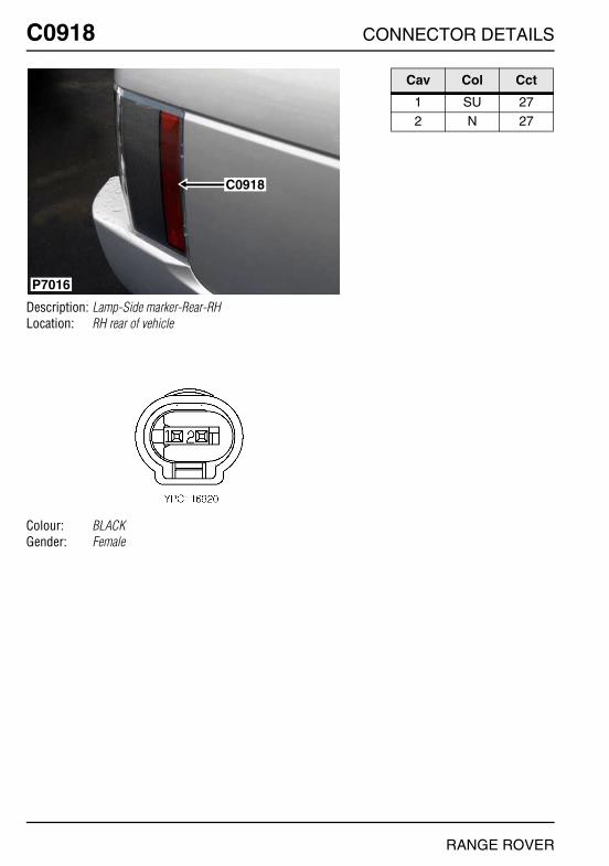
O
C0918 CC0918
Description: Lamp-Side marker-Rear-RHLocation: RH rear of vehicle
Colour: BLACKGender: Female
P7016
C0918
NNECTOR DETAILS
Cav Col Cct
1 SU 272 N 27
RANGE ROVER

CONNECTOR DETAILS
C0919
Description: Lamp-Side marker-Rear-LHLocation: LH rear of vehicle
Colour: BLACKGender: Female
C0919
P7017
RANGE ROVER
C0919
Cav Col Cct
1 SG 272 N 27
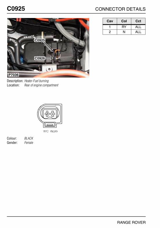
O
C0925 CC0925
Description: Heater-Fuel burningLocation: Rear of engine compartment
Colour: BLACKGender: Female
C0925
C0926
P7036
NNECTOR DETAILS
Cav Col Cct
1 RY ALL2 N ALL
RANGE ROVER

CONNECTOR DETAILS
C0926
Description: Heater-Fuel burningLocation: Rear of engine compartment
Colour: BLACKGender: Female
C0925
C0926
P7036
RANGE ROVER
C0926
Cav Col Cct
1 WG 82 WRY ALL6 BR ALL
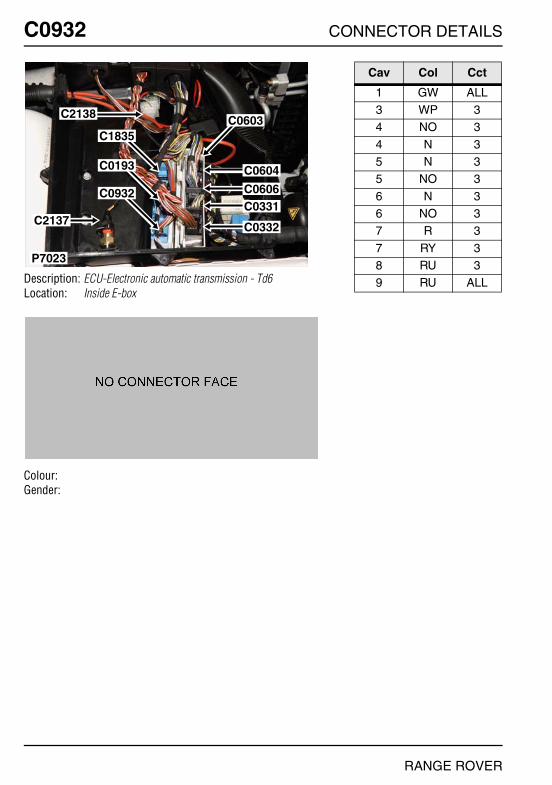
O
C0932 CC0932
Description: ECU-Electronic automatic transmission - Td6Location: Inside E-box
Colour:Gender:
P7023
C0604
C0603C2138
C1835
C0193
C0932
C2137
C0606C0331
C0332
NNECTOR DETAILS
Cav Col Cct
1 GW ALL3 WP 34 NO 3
4 N 35 N 35 NO 3
6 N 36 NO 37 R 3
7 RY 38 RU 39 RU ALL
RANGE ROVER

CONNECTOR DETAILS
C0934
Description: Washer jet-HeatedLocation: Under bonnet, RH side
Colour: BLACKGender: Female
P6881
C0934C0946
RANGE ROVER
C0934
Cav Col Cct
1 BG ALL2 N ALL

O
C0937 CC0937
Description: Module-Lighting switchLocation: Base of RH 'A' post
Colour: BLACKGender: Female
P6973
C0937
C2040
C2039
NNECTOR DETAILS
Cav Col Cct
1 UN 272 SP ALL3 SU ALL
4 YN ALL5 SN ALL6 UN ALL
7 NB ALL8 UG ALL9 YB ALL
10 BU ALL11 YG ALL12 SB ALL
13 YU ALL14 UY ALL15 R ALL
RANGE ROVER

CONNECTOR DETAILS
C0942
Description: Socket-AccessoryLocation: Beneath centre console
Colour:Gender:
P6910
C0350C0942
C2322
C0091
RANGE ROVER
C0942
Cav Col Cct
1 N 3

O
C0946 CC0946
Description: Heater-Washer jet-LHLocation: Under bonnet, LH side
Colour: BLACKGender: Female
P6881
C0934C0946
NNECTOR DETAILS
Cav Col Cct
1 BG ALL2 N ALL
RANGE ROVER
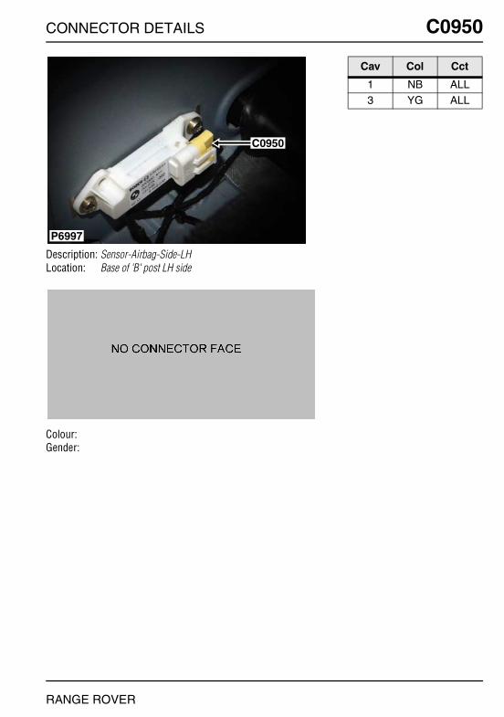
CONNECTOR DETAILS
C0950
Description: Sensor-Airbag-Side-LHLocation: Base of 'B' post LH side
Colour:Gender:
P6997
C0950
RANGE ROVER
C0950
Cav Col Cct
1 NB ALL3 YG ALL
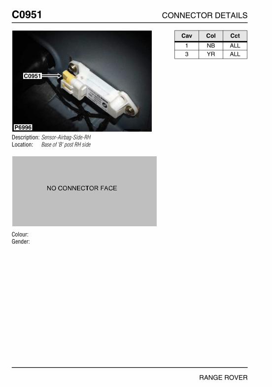
O
C0951 CC0951
Description: Sensor-Airbag-Side-RHLocation: Base of 'B' post RH side
Colour:Gender:
P6996
C0951
NNECTOR DETAILS
Cav Col Cct
1 NB ALL3 YR ALL
RANGE ROVER
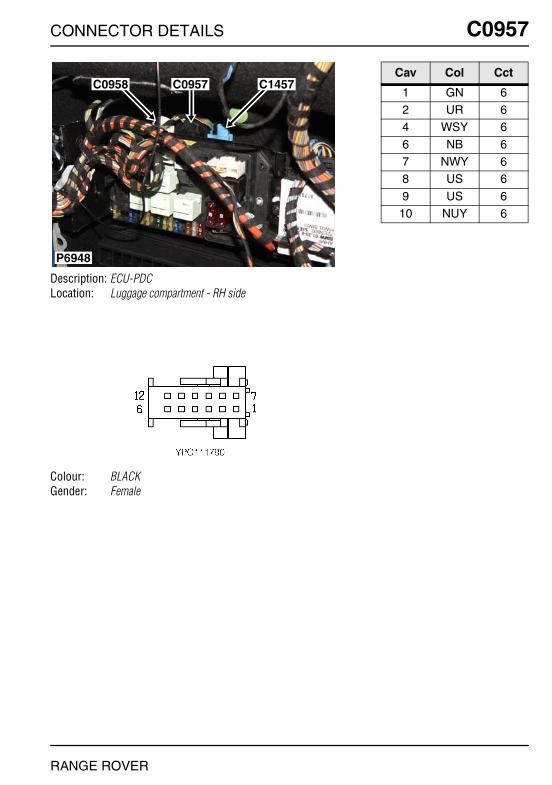
CONNECTOR DETAILS
C0957
Description: ECU-PDCLocation: Luggage compartment - RH side
Colour: BLACKGender: Female
P6948
C0958 C0957 C1457
RANGE ROVER
C0957
Cav Col Cct
1 GN 62 UR 64 WSY 6
6 NB 67 NWY 68 US 6
9 US 610 NUY 6

O
C0958 CC0958
Description: ECU-PDCLocation: Luggage compartment - RH side
Colour: BLACKGender: Female
P6948
C0958 C0957 C1457
NNECTOR DETAILS
Cav Col Cct
1 NB 62 NY 63 NW 6
4 GS 65 GN 66 GP 6
7 NU 68 YB 69 YG 6
10 YN 611 YS 612 GB 6
RANGE ROVER
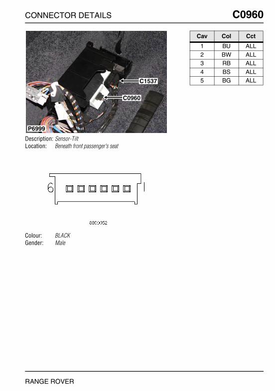
CONNECTOR DETAILS
C0960
Description: Sensor-TiltLocation: Beneath front passenger's seat
Colour: BLACKGender: Male
P6999
C1537
C0960
RANGE ROVER
C0960
Cav Col Cct
1 BU ALL2 BW ALL3 RB ALL
4 BS ALL5 BG ALL
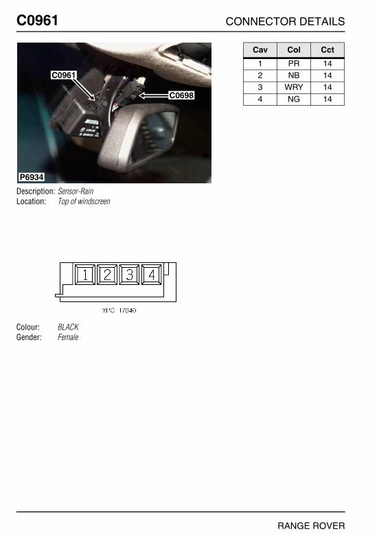
O
C0961 CC0961
Description: Sensor-RainLocation: Top of windscreen
Colour: BLACKGender: Female
P6934
C0961
C0698
NNECTOR DETAILS
Cav Col Cct
1 PR 142 NB 143 WRY 14
4 NG 14
RANGE ROVER

CONNECTOR DETAILS
C0963
Description: Sensor-PDC-Outer-Rear-LHLocation: Behind LH side of rear bumper
Colour: GREYGender: Female
P6945
C0964
C0963
RANGE ROVER
C0963
Cav Col Cct
1 GB 62 YS 63 NW 6

O
C0964 CC0964
Description: Sensor-PDC-Inner-Rear-LHLocation: Behind LH side of rear bumper
Colour: GREYGender: Female
P6945
C0964
C0963
NNECTOR DETAILS
Cav Col Cct
1 GN 62 YG 63 NB 6
RANGE ROVER
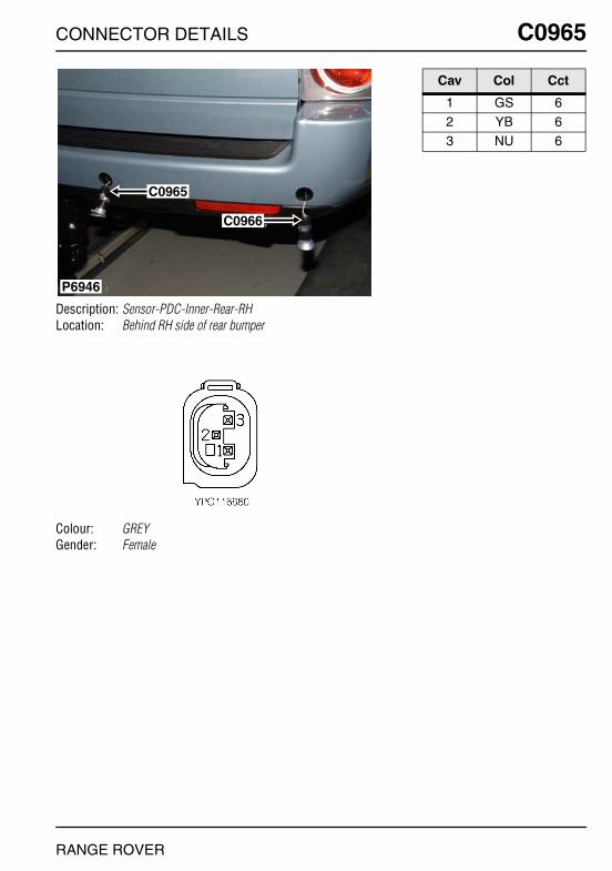
CONNECTOR DETAILS
C0965
Description: Sensor-PDC-Inner-Rear-RHLocation: Behind RH side of rear bumper
Colour: GREYGender: Female
P6946
C0966
C0965
RANGE ROVER
C0965
Cav Col Cct
1 GS 62 YB 63 NU 6
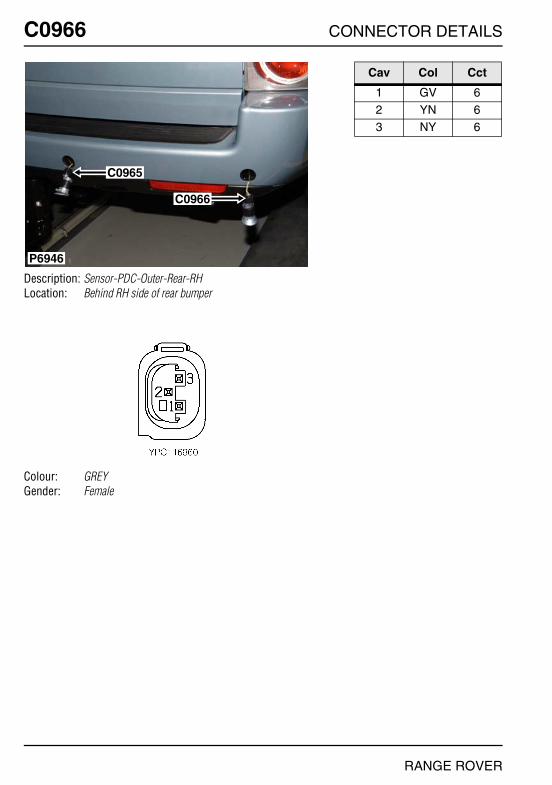
O
C0966 CC0966
Description: Sensor-PDC-Outer-Rear-RHLocation: Behind RH side of rear bumper
Colour: GREYGender: Female
P6946
C0966
C0965
NNECTOR DETAILS
Cav Col Cct
1 GV 62 YN 63 NY 6
RANGE ROVER
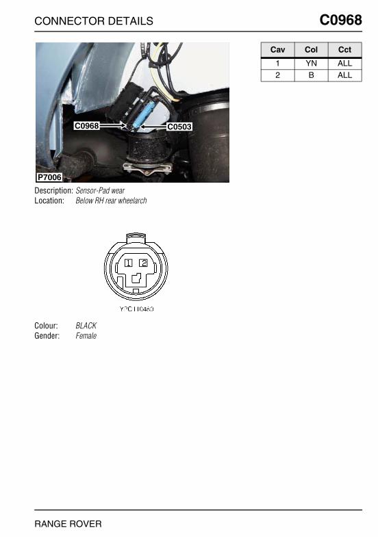
CONNECTOR DETAILS
C0968
Description: Sensor-Pad wearLocation: Below RH rear wheelarch
Colour: BLACKGender: Female
P7006
C0968 C0503
RANGE ROVER
C0968
Cav Col Cct
1 YN ALL2 B ALL

O
C0987 CC0987
Description: Speaker-PDCLocation: Luggage compartment - RH side
Colour: BLACKGender: Female
P6947
C0987
C0380
C0473C0498
C2046
C0690C1601
NNECTOR DETAILS
Cav Col Cct
1 US 62 UR 6
RANGE ROVER

CONNECTOR DETAILS
C0994
Description: Relay-Heated front screenLocation: Behind driver side of fascia
Colour: BLACKGender: Female
P6923
C0994 C1795
RANGE ROVER
C0994
Cav Col Cct
1 UN 92 GY 93 R 9
5 B 9

O
C1216 CC1216
Description: Switch-Oil pressure - Td6Location: LH side of engine
Colour:Gender:
P7027
C1216
C0053
NNECTOR DETAILS
Cav Col Cct
1 NG 3
RANGE ROVER
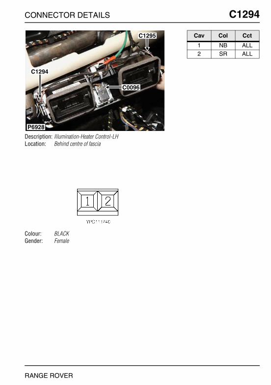
CONNECTOR DETAILS
C1294
Description: Illumination-Heater Control-LHLocation: Behind centre of fascia
Colour: BLACKGender: Female
P6928
C1294
C1295
C0096
RANGE ROVER
C1294
Cav Col Cct
1 NB ALL2 SR ALL

O
C1295 CC1295
Description: Illumination-Heater Control-RHLocation: Behind centre of fascia
Colour: BLACKGender: Female
P6928
C1294
C1295
C0096
NNECTOR DETAILS
Cav Col Cct
1 NB ALL2 SR ALL
RANGE ROVER
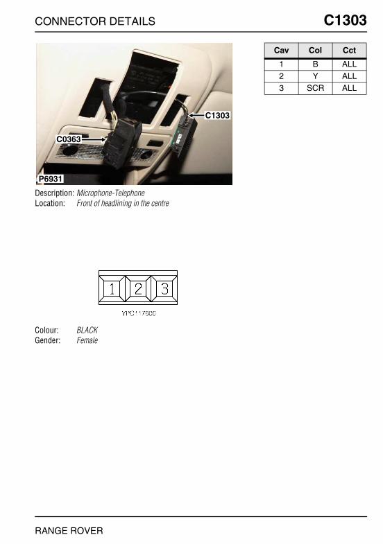
CONNECTOR DETAILS
C1303
Description: Microphone-TelephoneLocation: Front of headlining in the centre
Colour: BLACKGender: Female
P6931
C1303
C0363
RANGE ROVER
C1303
Cav Col Cct
1 B ALL2 Y ALL3 SCR ALL

O
C1319 CC1319
Description: ECU-Transfer boxLocation: Rear LH side of engine compartment
Colour: GREYGender: Female
P6886
C1319
C0546
C1455
C1854
C1855
NNECTOR DETAILS
Cav Col Cct
7 PU ALL8 WG ALL
13 YN ALL
15 GP ALL17 WR ALL18 WB ALL
19 WP ALL26 YB ALL
RANGE ROVER
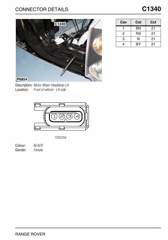
CONNECTOR DETAILS
C1340
Description: Motor-Wiper-Headlamp-LHLocation: Front of vehicle - LH side
Colour: BLACKGender: Female
C1340
P6854
RANGE ROVER
C1340
Cav Col Cct
1 BN 212 RS 213 N 21
4 BY 21
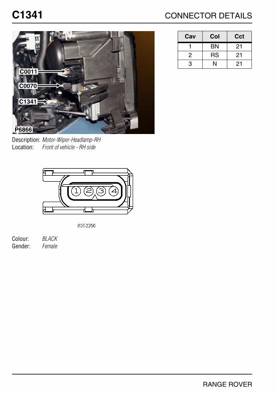
O
C1341 CC1341
Description: Motor-Wiper-Headlamp-RHLocation: Front of vehicle - RH side
Colour: BLACKGender: Female
P6866
C0011
C0070
C1341
NNECTOR DETAILS
Cav Col Cct
1 BN 212 RS 213 N 21
RANGE ROVER

CONNECTOR DETAILS
C1342
Description: Pump-Power washLocation: Front LH side of engine compartment
Colour: BLACKGender: Female
P6858
C0021
C1342C0008
C0620
RANGE ROVER
C1342
Cav Col Cct
1 N 212 BY 21

O
C1352 CC1352
Description: Speaker-PDCLocation: Driver's footwell
Colour: BLACKGender: Female
P6950
C1352
C1577
C0076
C0405
C0369
NNECTOR DETAILS
Cav Col Cct
2 WR ALL3 WU ALL
RANGE ROVER
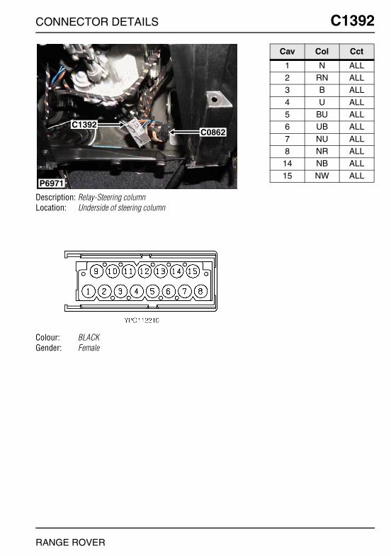
CONNECTOR DETAILS
C1392
Description: Relay-Steering columnLocation: Underside of steering column
Colour: BLACKGender: Female
P6971
C1392C0862
RANGE ROVER
C1392
Cav Col Cct
1 N ALL2 RN ALL3 B ALL
4 U ALL5 BU ALL6 UB ALL
7 NU ALL8 NR ALL
14 NB ALL
15 NW ALL

O
C1393 CC1393
Description: Switch-Steering columnLocation: Underside of steering column
Colour:Gender:
P6955
C1393
C0082
C2041
NNECTOR DETAILS
Cav Col Cct
1 NU ALL2 NR ALL3 NB ALL
4 NW ALL5 NB ALL
RANGE ROVER

CONNECTOR DETAILS
C1394
Description: Motor-Column-TelescopeLocation: Underside of steering column
Colour: BLACKGender: Female
P6972
C1397 C1394
RANGE ROVER
C1394
Cav Col Cct
1 BU 32 RN 33 N 3

O
C1395 CC1395
Description: Motor-Column-HeightLocation: Top of steering column
Colour: BLACKGender: Female
P6953C1396
C1832
C1395
NNECTOR DETAILS
Cav Col Cct
1 B 32 RN 33 N 3
RANGE ROVER

CONNECTOR DETAILS
C1396
Description: Motor-Column-TelescopeLocation: Top of steering column
Colour: BLACKGender: Female
P6953C1396
C1832
C1395
RANGE ROVER
C1396
Cav Col Cct
1 U ALL2 B ALL
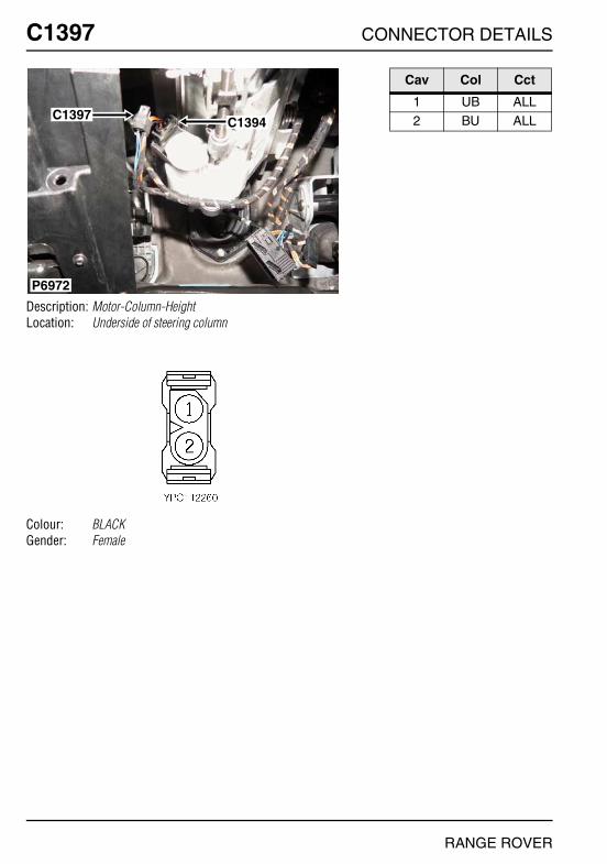
O
C1397 CC1397
Description: Motor-Column-HeightLocation: Underside of steering column
Colour: BLACKGender: Female
P6972
C1397 C1394
NNECTOR DETAILS
Cav Col Cct
1 UB ALL2 BU ALL
RANGE ROVER
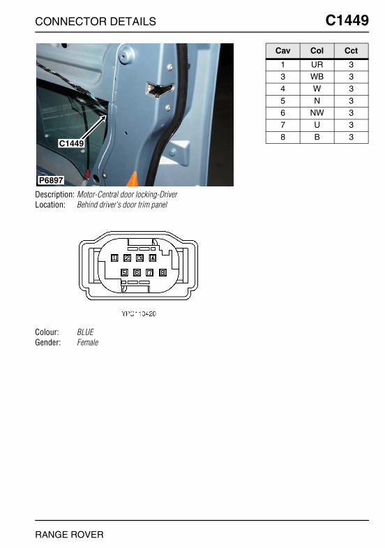
CONNECTOR DETAILS
C1449
Description: Motor-Central door locking-DriverLocation: Behind driver's door trim panel
Colour: BLUEGender: Female
P6897
C1449
RANGE ROVER
C1449
Cav Col Cct
1 UR 33 WB 34 W 3
5 N 36 NW 37 U 3
8 B 3

O
C1451 CC1451
Description: Motor-Central door locking-PassengerLocation: Behind passenger's door trim panel
Colour: BLUEGender: Female
P6900
C1451
NNECTOR DETAILS
Cav Col Cct
4 W 35 N 36 NW 3
7 U 38 B 3
RANGE ROVER

CONNECTOR DETAILS
C1455
Description: Relay-InterlockLocation: Rear LH side of engine compartment
Colour: BLACKGender: Female
P6886
C1319
C0546
C1455
C1854
C1855
RANGE ROVER
C1455
Cav Col Cct
2 B 24 YN 26 B 2
8 UB 2
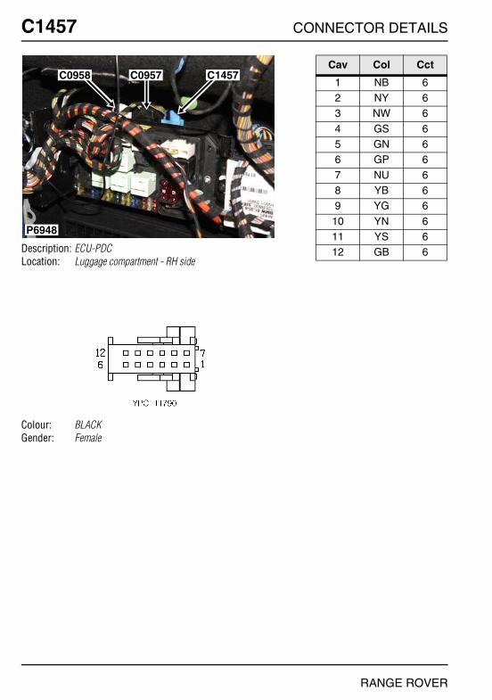
O
C1457 CC1457
Description: ECU-PDCLocation: Luggage compartment - RH side
Colour: BLACKGender: Female
P6948
C0958 C0957 C1457
NNECTOR DETAILS
Cav Col Cct
1 NB 62 NY 63 NW 6
4 GS 65 GN 66 GP 6
7 NU 68 YB 69 YG 6
10 YN 611 YS 612 GB 6
RANGE ROVER

CONNECTOR DETAILS
C1474
Description: Airbag-ITS-Rear-LHLocation: Rear of headlining
Colour: BLACKGender: Female
P7002
C1474
RANGE ROVER
C1474
Cav Col Cct
1 Y 202 B 20
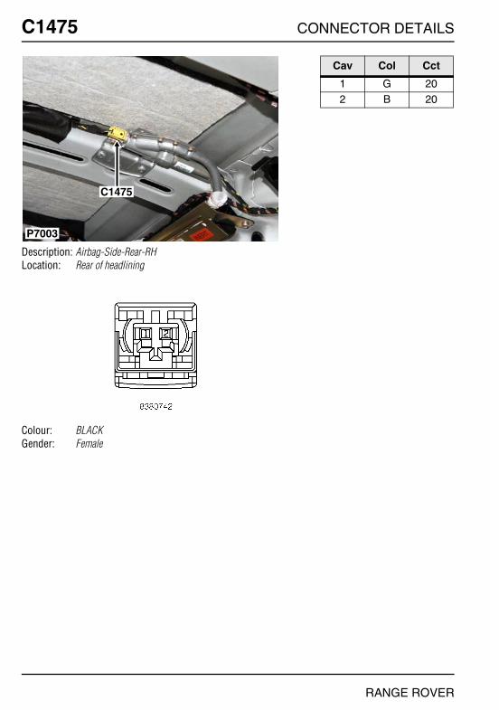
O
C1475 CC1475
Description: Airbag-Side-Rear-RHLocation: Rear of headlining
Colour: BLACKGender: Female
P7003
C1475
NNECTOR DETAILS
Cav Col Cct
1 G 202 B 20
RANGE ROVER
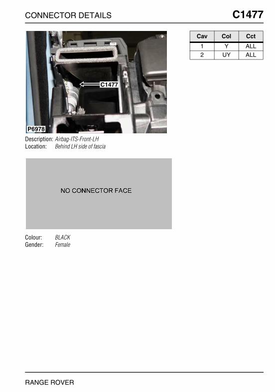
CONNECTOR DETAILS
C1477
Description: Airbag-ITS-Front-LHLocation: Behind LH side of fascia
Colour: BLACKGender: Female
P6978
C1477
RANGE ROVER
C1477
Cav Col Cct
1 Y ALL2 UY ALL
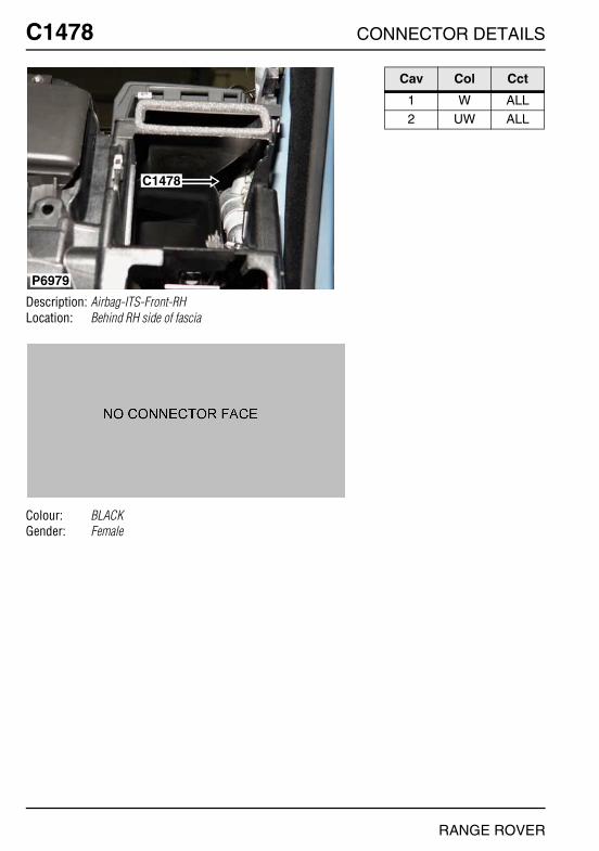
O
C1478 CC1478
Description: Airbag-ITS-Front-RHLocation: Behind RH side of fascia
Colour: BLACKGender: Female
P6979
C1478
NNECTOR DETAILS
Cav Col Cct
1 W ALL2 UW ALL
RANGE ROVER

CONNECTOR DETAILS
C1495
Description: Lamp-Number plate and tail door switchLocation: Centre of taildoor, behind trim panel
Colour: NATURALGender: Female
P6989
C1495
C0383
RANGE ROVER
C1495
Cav Col Cct
1 SN ALL2 N ALL3 SY ALL
4 SB ALL
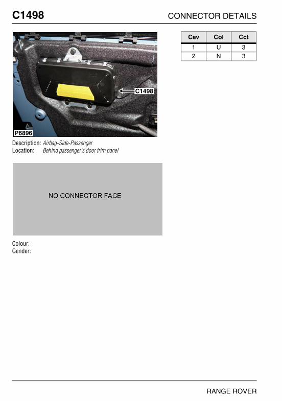
O
C1498 CC1498
Description: Airbag-Side-PassengerLocation: Behind passenger's door trim panel
Colour:Gender:
P6896
C1498
NNECTOR DETAILS
Cav Col Cct
1 U 32 N 3
RANGE ROVER

CONNECTOR DETAILS
C1499
Description: Airbag-Side-DriverLocation: Behind driver's door trim panel
Colour:Gender:
P6891
C1499
RANGE ROVER
C1499
Cav Col Cct
1 Y 32 N 3

O
C1500 CC1500
Description: Glow plug - Td6Location: LH side of engine
Colour:Gender:
C1501C1500
C0479
C0478
C0477
C0476
P7032
NNECTOR DETAILS
Cav Col Cct
1 BW 3
RANGE ROVER

CONNECTOR DETAILS
C1501
Description: Glow plug - Td6Location: LH side of engine
Colour:Gender:
C1501C1500
C0479
C0478
C0477
C0476
P7032
RANGE ROVER
C1501
Cav Col Cct
1 BN 3
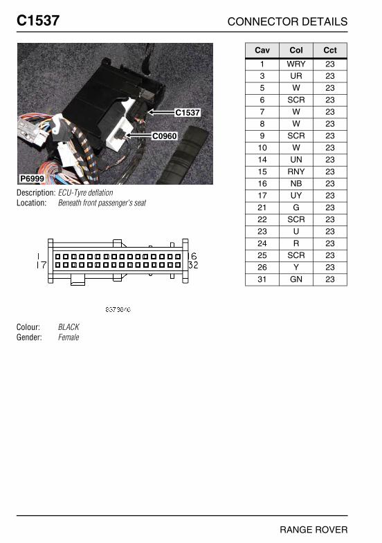
O
C1537 CC1537
Description: ECU-Tyre deflationLocation: Beneath front passenger's seat
Colour: BLACKGender: Female
P6999
C1537
C0960
NNECTOR DETAILS
Cav Col Cct
1 WRY 233 UR 235 W 23
6 SCR 237 W 238 W 23
9 SCR 2310 W 2314 UN 23
15 RNY 2316 NB 2317 UY 23
21 G 2322 SCR 2323 U 23
24 R 2325 SCR 2326 Y 23
31 GN 23
RANGE ROVER

CONNECTOR DETAILS
C1543
Description: ECU-Headlamp levellingLocation: Passenger's footwell
Colour: GREYGender: Female
P6977
C0554
C1543
RANGE ROVER
C1543
Cav Col Cct
1 YR 222 YN 223 UR 22
4 UN 225 WN 227 SN 22
8 UN 229 UB 22
10 YB 22
11 YN 2213 YR 2214 WRY 22
16 WS 2218 WB 2220 SW 22
21 UR 2222 SB 2224 YW 22
26 NB 22
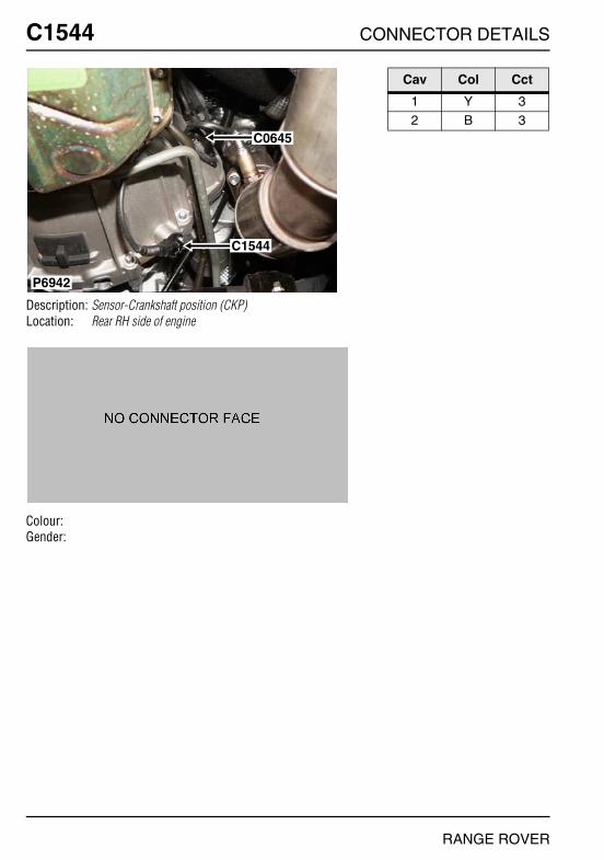
O
C1544 CC1544
Description: Sensor-Crankshaft position (CKP)Location: Rear RH side of engine
Colour:Gender:
P6942
C0645
C1544
NNECTOR DETAILS
Cav Col Cct
1 Y 32 B 3
RANGE ROVER

CONNECTOR DETAILS
C1548
Description: Sensor-Air Temperature Control (ATC)Location: Front of engine compartment - centre
Colour: BLACKGender: Female
P6864
C0005
C1548
RANGE ROVER
C1548
Cav Col Cct
1 N 52 Y 53 N 5
4 U 5
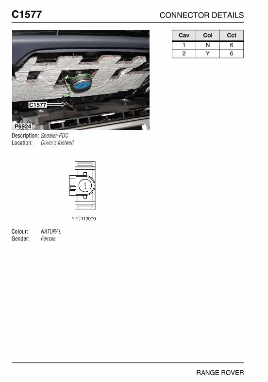
O
C1577 CC1577
Description: Speaker-PDCLocation: Driver's footwell
Colour: NATURALGender: Female
P6924
C1577
NNECTOR DETAILS
Cav Col Cct
1 N 62 Y 6
RANGE ROVER
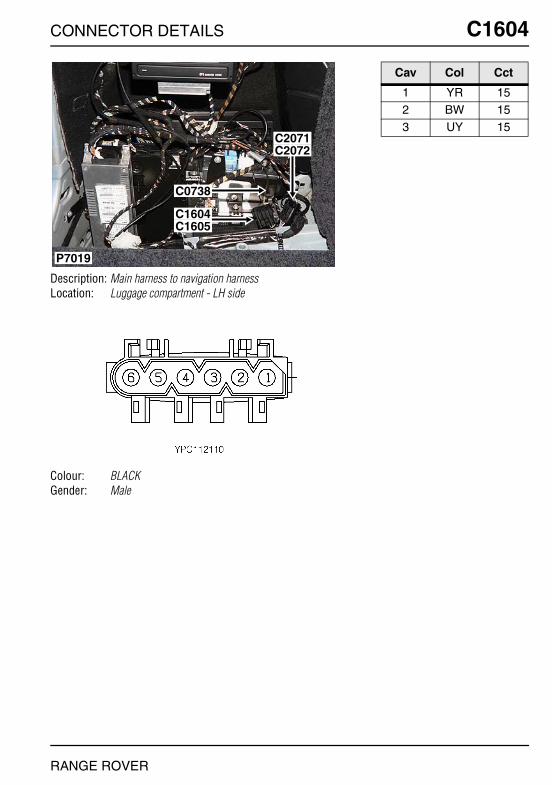
CONNECTOR DETAILS
C1604
Description: Main harness to navigation harnessLocation: Luggage compartment - LH side
Colour: BLACKGender: Male
P7019
C2072C2071
C1605C1604
C0738
RANGE ROVER
C1604
Cav Col Cct
1 YR 152 BW 153 UY 15
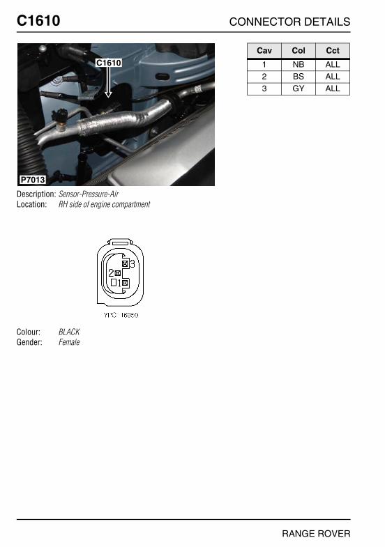
O
C1610 CC1610
Description: Sensor-Pressure-AirLocation: RH side of engine compartment
Colour: BLACKGender: Female
P7013
C1610
NNECTOR DETAILS
Cav Col Cct
1 NB ALL2 BS ALL3 GY ALL
RANGE ROVER

CONNECTOR DETAILS
C1611
Description: Sensor-Pressure-AirLocation: Beneath vehicle - RH side
Colour: BLACKGender: Female
P7008C1611
RANGE ROVER
C1611
Cav Col Cct
1 W ALL2 U ALL3 Y ALL
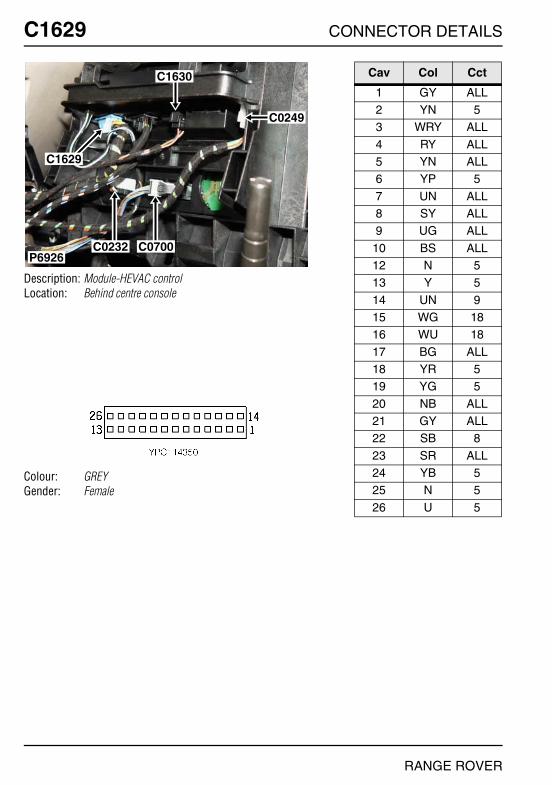
O
C1629 CC1629
Description: Module-HEVAC controlLocation: Behind centre console
Colour: GREYGender: Female
P6926C0232 C0700
C1629
C1630
C0249
NNECTOR DETAILS
Cav Col Cct
1 GY ALL2 YN 53 WRY ALL
4 RY ALL5 YN ALL6 YP 5
7 UN ALL8 SY ALL9 UG ALL
10 BS ALL12 N 513 Y 5
14 UN 915 WG 1816 WU 18
17 BG ALL18 YR 519 YG 5
20 NB ALL21 GY ALL22 SB 8
23 SR ALL24 YB 525 N 5
26 U 5
RANGE ROVER

CONNECTOR DETAILS
C1630
Description: Module-HEVAC controlLocation: Behind centre console
Colour: BLACKGender: Female
P6926C0232 C0700
C1629
C1630
C0249
RANGE ROVER
C1630
Cav Col Cct
1 RP ALL2 BS ALL3 N ALL
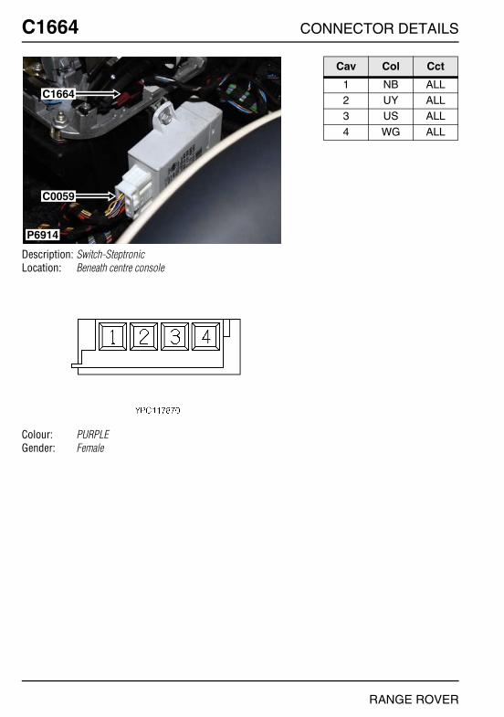
O
C1664 CC1664
Description: Switch-SteptronicLocation: Beneath centre console
Colour: PURPLEGender: Female
P6914
C1664
C0059
NNECTOR DETAILS
Cav Col Cct
1 NB ALL2 UY ALL3 US ALL
4 WG ALL
RANGE ROVER
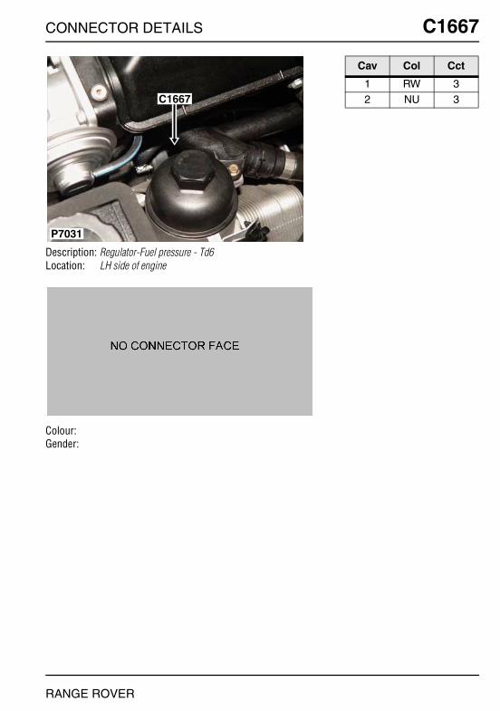
CONNECTOR DETAILS
C1667
Description: Regulator-Fuel pressure - Td6Location: LH side of engine
Colour:Gender:
C1667
P7031
RANGE ROVER
C1667
Cav Col Cct
1 RW 32 NU 3

O
C1696 CC1696
Description: Sensor-Height-Front-LHLocation: Behind LH front wheel arch liner
Colour: BLACKGender: Female
P6878
C1696
NNECTOR DETAILS
Cav Col Cct
1 SN ALL4 SW ALL5 SB ALL
RANGE ROVER
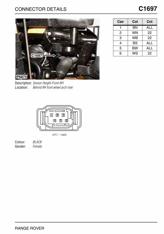
CONNECTOR DETAILS
C1697
Description: Sensor-Height-Front-RHLocation: Behind RH front wheel arch liner
Colour: BLACKGender: Female
P6875
C1697
RANGE ROVER
C1697
Cav Col Cct
1 BN ALL2 WN 223 WB 22
4 BS ALL5 BW ALL6 WS 22
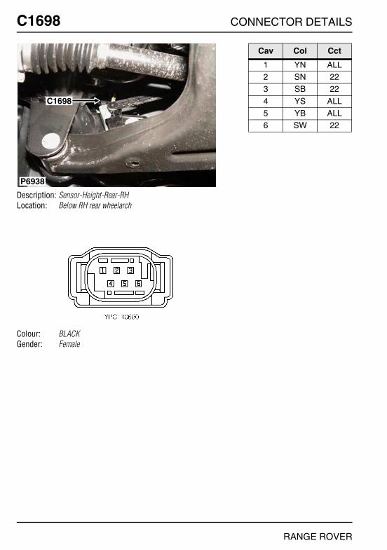
O
C1698 CC1698
Description: Sensor-Height-Rear-RHLocation: Below RH rear wheelarch
Colour: BLACKGender: Female
P6938
C1698
NNECTOR DETAILS
Cav Col Cct
1 YN ALL2 SN 223 SB 22
4 YS ALL5 YB ALL6 SW 22
RANGE ROVER
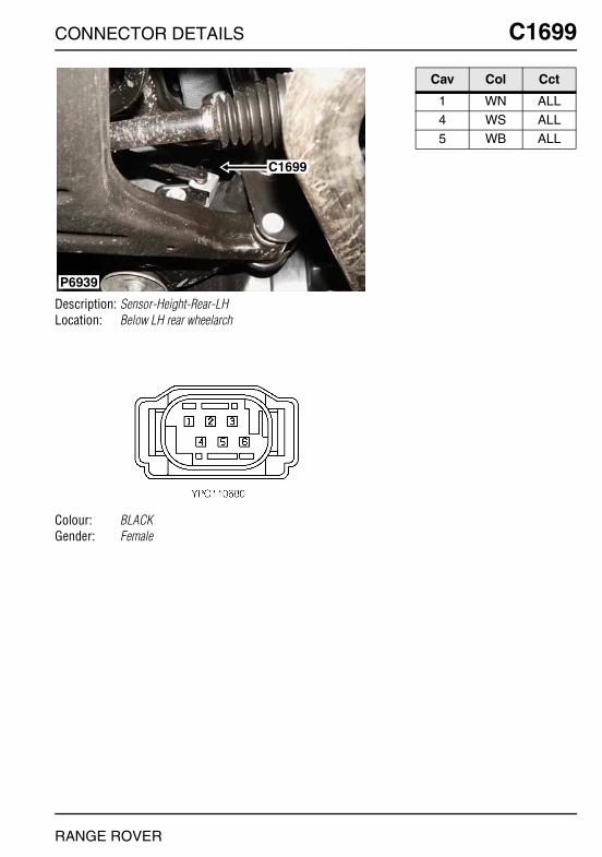
CONNECTOR DETAILS
C1699
Description: Sensor-Height-Rear-LHLocation: Below LH rear wheelarch
Colour: BLACKGender: Female
P6939
C1699
RANGE ROVER
C1699
Cav Col Cct
1 WN ALL4 WS ALL5 WB ALL
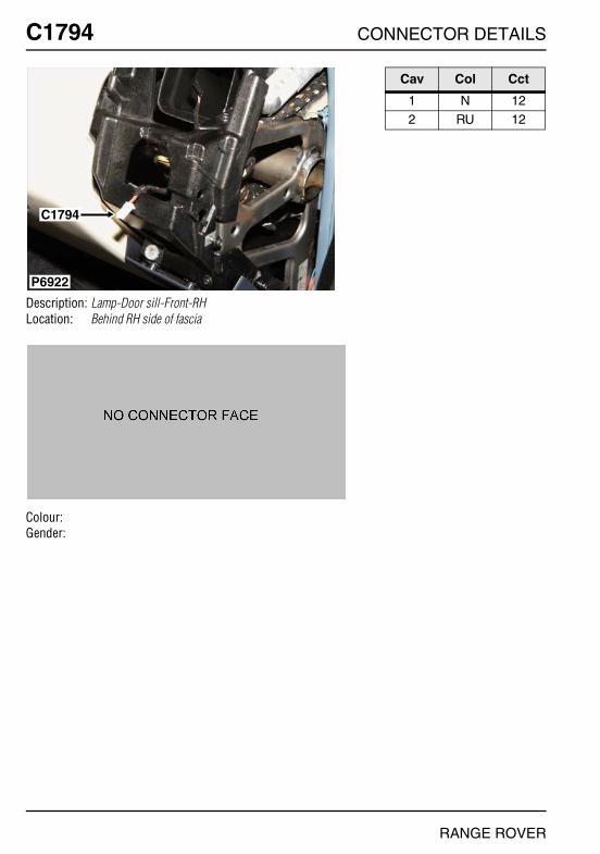
O
C1794 CC1794
Description: Lamp-Door sill-Front-RHLocation: Behind RH side of fascia
Colour:Gender:
P6922
C1794
NNECTOR DETAILS
Cav Col Cct
1 N 122 RU 12
RANGE ROVER

CONNECTOR DETAILS
C1795
Description: Lamp-Door sill-Front-LHLocation: Behind LH side of fascia
Colour:Gender:
P6923
C0994 C1795
RANGE ROVER
C1795
Cav Col Cct
1 N 122 RU 12
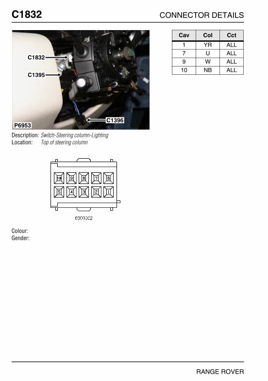
O
C1832 CC1832
Description: Switch-Steering column-LightingLocation: Top of steering column
Colour:Gender:
P6953C1396
C1832
C1395
NNECTOR DETAILS
Cav Col Cct
1 YR ALL7 U ALL9 W ALL
10 NB ALL
RANGE ROVER

CONNECTOR DETAILS
C1835
Description: ECU-Electronic automatic transmission - Td6Location: Inside E-box
Colour:Gender:
P7023
C0604
C0603C2138
C1835
C0193
C0932
C2137
C0606C0331
C0332
RANGE ROVER
C1835
Cav Col Cct
1 O 32 SCR 32 YU 3
3 G 33 N 34 Y 3
5 SCR 36 BY 36 YR 3
7 TB 38 R 39 Y 26
10 GR 311 P 313 W 3
14 P 314 PB 315 YB 3
16 TB 316 Y 317 B 3
17 K 318 BR 2419 WR 3
20 OB 321 YU 322 BR 3
23 U 324 S 324 O 9
25 SCR 226 G 326 R 25
27 B 331 G 332 WPY 3
33 S 3
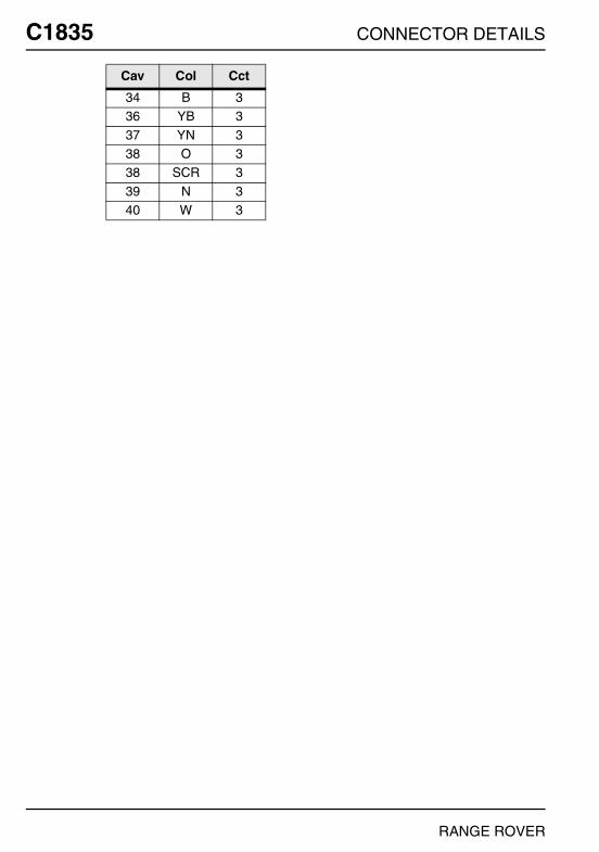
O
C1835 C34 B 336 YB 3
37 YN 338 O 338 SCR 3
39 N 340 W 3
Cav Col Cct
NNECTOR DETAILS
RANGE ROVER

CONNECTOR DETAILS
C1858
Description: Transfer gearbox - V8Location: LH side of transfer box
Colour:Gender:
P6941
C0643
C1858
RANGE ROVER
C1858
Cav Col Cct
1 N 32 Y 34 B 3
6 RW 37 N 59 RW 3
10 N 3

O
C1886 CC1886
Description: Relay-Air injection pumpLocation: Inside E-box
Colour:Gender:
P6882
C0448
C2138
C0193
C0331
C1886
C0646
C2137
NNECTOR DETAILS
Cav Col Cct
2 R 24 NU 25 N 2
6 BRY 28 RW 2
RANGE ROVER

CONNECTOR DETAILS
C1889
Description: BatteryLocation: Rear of engine compartment
Colour: YELLOWGender: Female
P6885
C1889
RANGE ROVER
C1889
Cav Col Cct
1 N ALL2 NR ALL

O
C1895 CC1895
Description: Relay-Engine control module (ECM) - Td6Location: Inside E-box
Colour:Gender:
P7022
C0162
C0909C1526
C0190
C0189
C0570
C1895
NNECTOR DETAILS
Cav Col Cct
2 RW 34 N 35 RW 3
6 R 3
RANGE ROVER
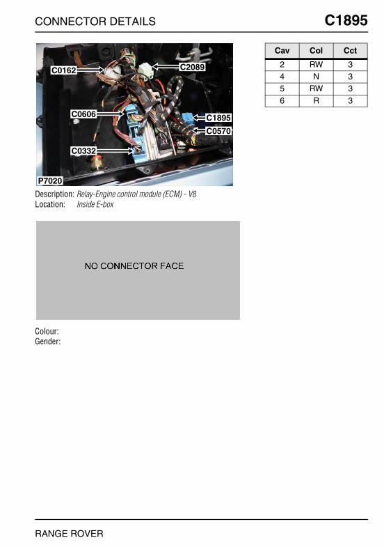
CONNECTOR DETAILS
C1895
Description: Relay-Engine control module (ECM) - V8Location: Inside E-box
Colour:Gender:
P7020
C0162
C0606
C0332
C2089
C1895
C0570
RANGE ROVER
C1895
Cav Col Cct
2 RW 34 N 35 RW 3
6 R 3

O
C2003 CC2003
Description: PDC harness to main harnessLocation: Rear of luggage compartment
Colour:Gender:
P6951
C0876C2003
NNECTOR DETAILS
Cav Col Cct
1 NB 62 NY 63 NW 6
4 GS 65 GN 66 GV 6
7 NU 68 YB 69 YG 6
10 YN 611 YS 612 GB 6
RANGE ROVER

CONNECTOR DETAILS
C2015
Description: Sensor-Anti-trap-Rear-RHLocation: Behind rear door trim panel
Colour:Gender:
P6903
C0732C2015
C0311
RANGE ROVER
C2015
Cav Col Cct
1 N 32 NY 3
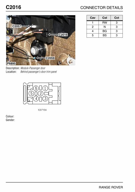
O
C2016 CC2016
Description: Module-Passenger doorLocation: Behind passenger's door trim panel
Colour:Gender:
P6895
C2057
C2016
C2059
NNECTOR DETAILS
Cav Col Cct
1 RW 32 N 34 BG 3
5 BS 3
RANGE ROVER

CONNECTOR DETAILS
C2017
Description: Module-Drivers doorLocation: Behind driver's door trim panel
Colour:Gender:
P6890
C2271
C2017
C2186
C2058
C2060
RANGE ROVER
C2017
Cav Col Cct
1 RV 32 N 34 BG 3
5 BS 3
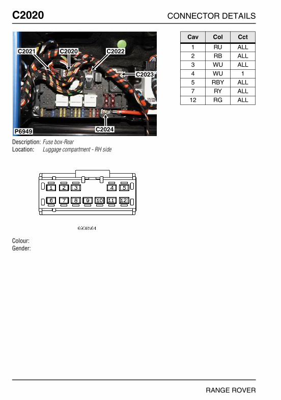
O
C2020 CC2020
Description: Fuse box-RearLocation: Luggage compartment - RH side
Colour:Gender:
P6949
C2021 C2022
C2023
C2020
C2024
NNECTOR DETAILS
Cav Col Cct
1 RU ALL2 RB ALL3 WU ALL
4 WU 15 RBY ALL7 RY ALL
12 RG ALL
RANGE ROVER
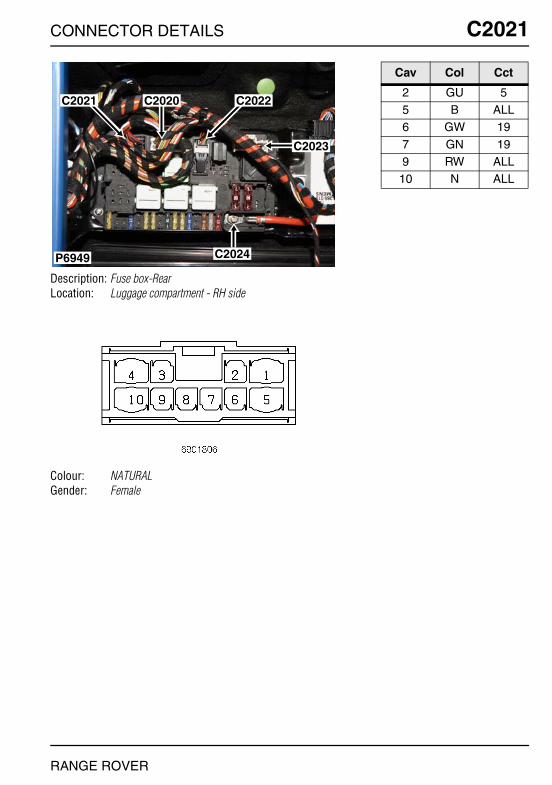
CONNECTOR DETAILS
C2021
Description: Fuse box-RearLocation: Luggage compartment - RH side
Colour: NATURALGender: Female
P6949
C2021 C2022
C2023
C2020
C2024
RANGE ROVER
C2021
Cav Col Cct
2 GU 55 B ALL6 GW 19
7 GN 199 RW ALL
10 N ALL

O
C2022 CC2022
Description: Fuse box-RearLocation: Luggage compartment - RH side
Colour: GREYGender: Female
P6949
C2021 C2022
C2023
C2020
C2024
NNECTOR DETAILS
Cav Col Cct
1 B ALL9 GY ALL
10 GY ALL
14 NY ALL15 UY ALL16 UW ALL
17 RS ALL21 RB 1122 BP ALL
23 RW ALL26 UN ALL
RANGE ROVER
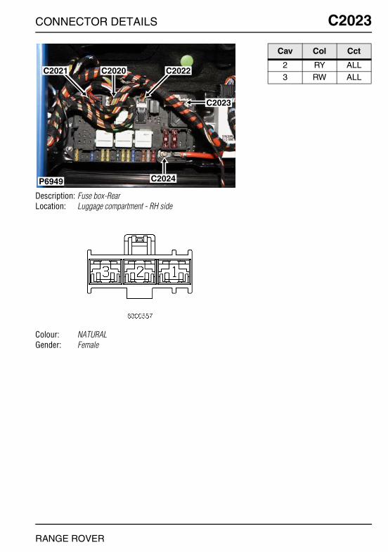
CONNECTOR DETAILS
C2023
Description: Fuse box-RearLocation: Luggage compartment - RH side
Colour: NATURALGender: Female
P6949
C2021 C2022
C2023
C2020
C2024
RANGE ROVER
C2023
Cav Col Cct
2 RY ALL3 RW ALL
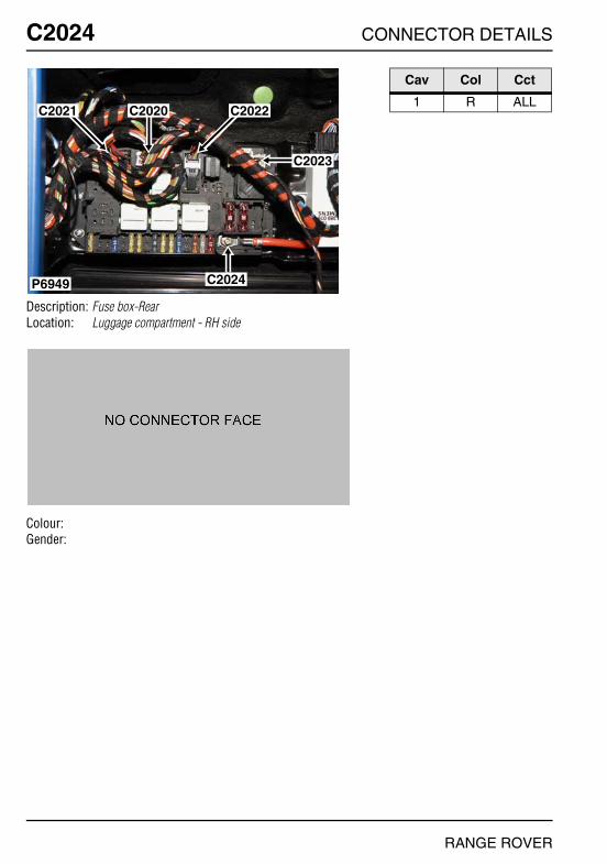
O
C2024 CC2024
Description: Fuse box-RearLocation: Luggage compartment - RH side
Colour:Gender:
P6949
C2021 C2022
C2023
C2020
C2024
NNECTOR DETAILS
Cav Col Cct
1 R ALL
RANGE ROVER
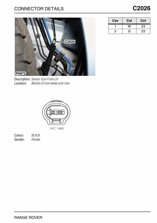
CONNECTOR DETAILS
C2026
Description: Sensor-Tyre-Front-LHLocation: Behind LH front wheel arch liner
Colour: BLACKGender: Female
P6872
C2026
RANGE ROVER
C2026
Cav Col Cct
1 W 232 G 23

O
C2027 CC2027
Description: Sensor-Tyre-Front-RHLocation: Behind RH front wheel arch liner
Colour: BLACKGender: Female
P6870
C2032
C0333C0420
C2027
NNECTOR DETAILS
Cav Col Cct
1 W 232 U 23
RANGE ROVER

CONNECTOR DETAILS
C2028
Description: Sensor-Tyre-Rear-LHLocation: Below LH rear wheelarch
Colour: BLACKGender: Female
P7009
C2028 C0502
RANGE ROVER
C2028
Cav Col Cct
1 W 232 R 23
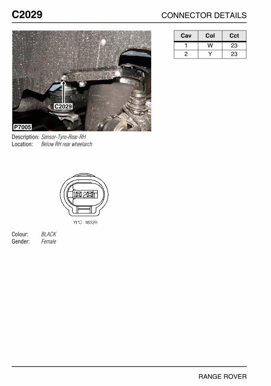
O
C2029 CC2029
Description: Sensor-Tyre-Rear-RHLocation: Below RH rear wheelarch
Colour: BLACKGender: Female
P7005
C2029
NNECTOR DETAILS
Cav Col Cct
1 W 232 Y 23
RANGE ROVER
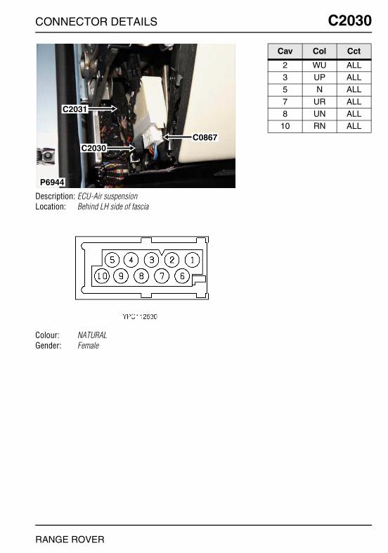
CONNECTOR DETAILS
C2030
Description: ECU-Air suspensionLocation: Behind LH side of fascia
Colour: NATURALGender: Female
C2031
C2030C0867
P6944
RANGE ROVER
C2030
Cav Col Cct
2 WU ALL3 UP ALL5 N ALL
7 UR ALL8 UN ALL
10 RN ALL
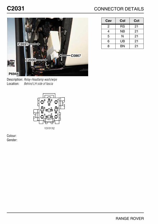
O
C2031 CC2031
Description: Relay-Headlamp wash/wipeLocation: Behind LH side of fascia
Colour:Gender:
C2031
C2030C0867
P6944
NNECTOR DETAILS
Cav Col Cct
2 RS 214 NB 215 N 21
6 UB 218 BN 21
RANGE ROVER
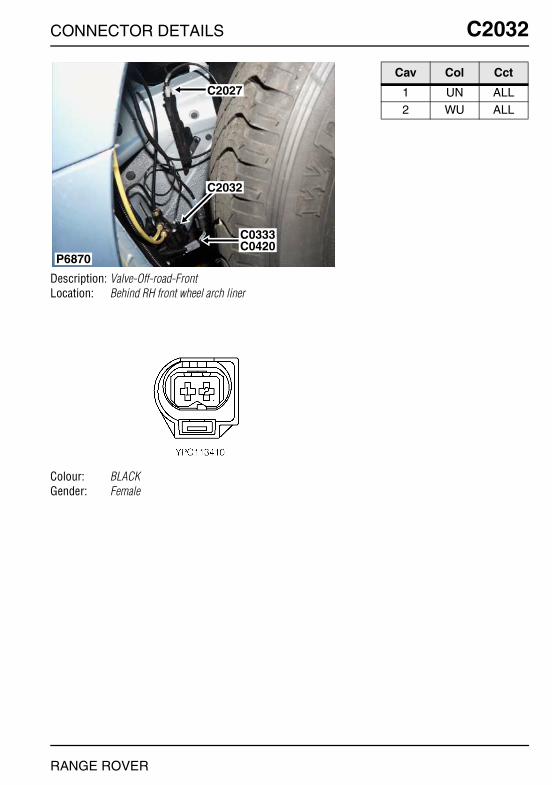
CONNECTOR DETAILS
C2032
Description: Valve-Off-road-FrontLocation: Behind RH front wheel arch liner
Colour: BLACKGender: Female
P6870
C2032
C0333C0420
C2027
RANGE ROVER
C2032
Cav Col Cct
1 UN ALL2 WU ALL
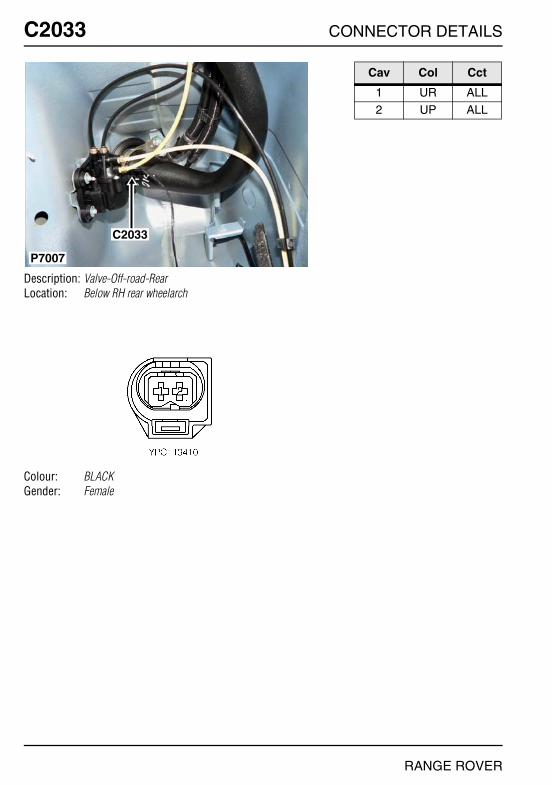
O
C2033 CC2033
Description: Valve-Off-road-RearLocation: Below RH rear wheelarch
Colour: BLACKGender: Female
P7007
C2033
NNECTOR DETAILS
Cav Col Cct
1 UR ALL2 UP ALL
RANGE ROVER
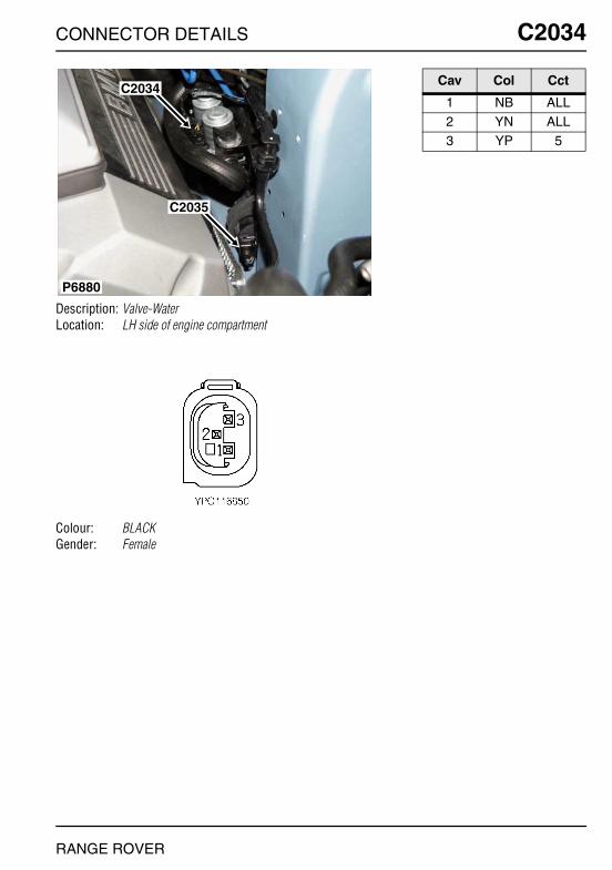
CONNECTOR DETAILS
C2034
Description: Valve-WaterLocation: LH side of engine compartment
Colour: BLACKGender: Female
P6880
C2034
C2035
RANGE ROVER
C2034
Cav Col Cct
1 NB ALL2 YN ALL3 YP 5

O
C2035 CC2035
Description: Pump-WaterLocation: LH side of engine compartment
Colour:Gender:
P6880
C2034
C2035
NNECTOR DETAILS
Cav Col Cct
1 N ALL2 UG ALL
RANGE ROVER
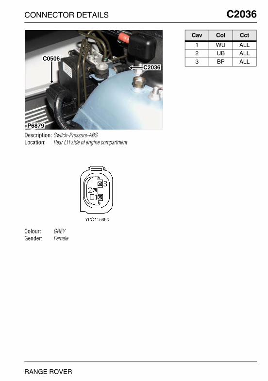
CONNECTOR DETAILS
C2036
Description: Switch-Pressure-ABSLocation: Rear LH side of engine compartment
Colour: GREYGender: Female
P6879
C0506
C2036
RANGE ROVER
C2036
Cav Col Cct
1 WU ALL2 UB ALL3 BP ALL
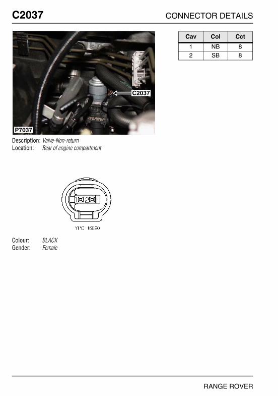
O
C2037 CC2037
Description: Valve-Non-returnLocation: Rear of engine compartment
Colour: BLACKGender: Female
C2037
P7037
NNECTOR DETAILS
Cav Col Cct
1 NB 82 SB 8
RANGE ROVER

CONNECTOR DETAILS
C2038
Description: Valve-ServotronicLocation: Behind RH front wheel arch liner
Colour: GREYGender: Female
P6876
C2038
RANGE ROVER
C2038
Cav Col Cct
1 BW ALL2 BR ALL
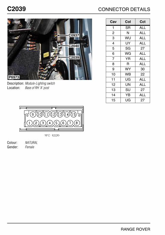
O
C2039 CC2039
Description: Module-Lighting switchLocation: Base of RH 'A' post
Colour: NATURALGender: Female
P6973
C0937
C2040
C2039
NNECTOR DETAILS
Cav Col Cct
1 SR ALL2 N ALL3 WU ALL
4 UY ALL5 SG 276 WG ALL
7 YR ALL8 R ALL9 WY 30
10 WB 2211 UG ALL12 UN ALL
13 SU 2714 YB ALL15 UG 27
RANGE ROVER
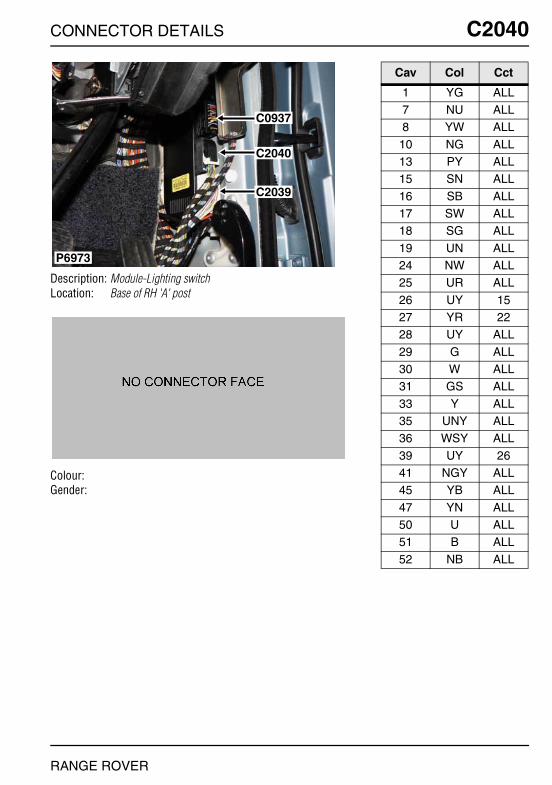
CONNECTOR DETAILS
C2040
Description: Module-Lighting switchLocation: Base of RH 'A' post
Colour:Gender:
P6973
C0937
C2040
C2039
RANGE ROVER
C2040
Cav Col Cct
1 YG ALL7 NU ALL8 YW ALL
10 NG ALL13 PY ALL15 SN ALL
16 SB ALL17 SW ALL18 SG ALL
19 UN ALL24 NW ALL25 UR ALL
26 UY 1527 YR 2228 UY ALL
29 G ALL30 W ALL31 GS ALL
33 Y ALL35 UNY ALL36 WSY ALL
39 UY 2641 NGY ALL45 YB ALL
47 YN ALL50 U ALL51 B ALL
52 NB ALL
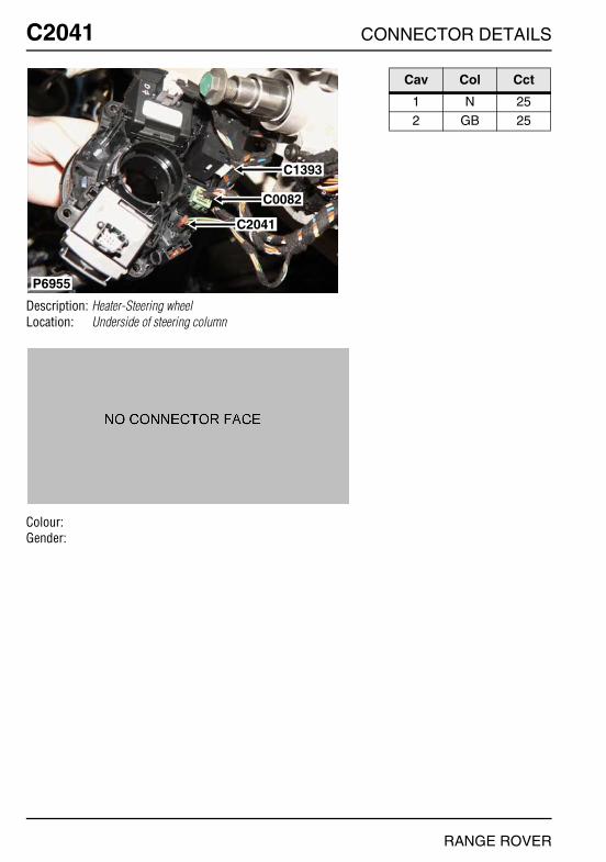
O
C2041 CC2041
Description: Heater-Steering wheelLocation: Underside of steering column
Colour:Gender:
P6955
C1393
C0082
C2041
NNECTOR DETAILS
Cav Col Cct
1 N 252 GB 25
RANGE ROVER
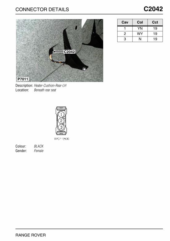
CONNECTOR DETAILS
C2042
Description: Heater-Cushion-Rear-LHLocation: Beneath rear seat
Colour: BLACKGender: Female
C2042
P7011
RANGE ROVER
C2042
Cav Col Cct
1 YN 192 WY 193 N 19
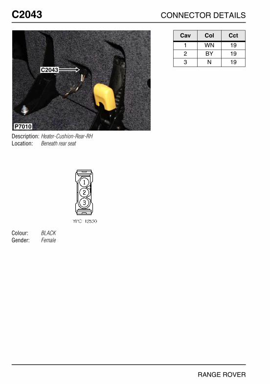
O
C2043 CC2043
Description: Heater-Cushion-Rear-RHLocation: Beneath rear seat
Colour: BLACKGender: Female
C2043
P7010
NNECTOR DETAILS
Cav Col Cct
1 WN 192 BY 193 N 19
RANGE ROVER

CONNECTOR DETAILS
C2045
Description: Main harness to telephone harnessLocation: Luggage compartment - LH side
Colour: NATURALGender: Male
P6980
C0493
C2234C2045C2066
C0492
C0491
C0947
RANGE ROVER
C2045
Cav Col Cct
1 RY ALL2 PW ALL3 UY 27
4 WSY ALL5 SR ALL6 W 27
7 NB ALL8 WN ALL9 BW ALL
10 BN ALL11 WG ALL12 YN 27
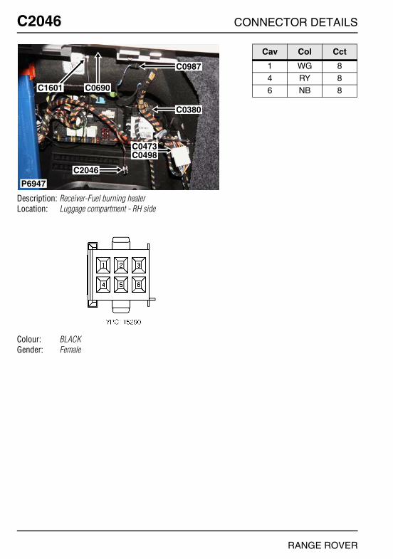
O
C2046 CC2046
Description: Receiver-Fuel burning heaterLocation: Luggage compartment - RH side
Colour: BLACKGender: Female
P6947
C0987
C0380
C0473C0498
C2046
C0690C1601
NNECTOR DETAILS
Cav Col Cct
1 WG 84 RY 86 NB 8
RANGE ROVER

CONNECTOR DETAILS
C2047
Description: Lamp-Load space-RHLocation: Luggage compartment - RH side
Colour: BLACKGender: Female
P6959
C2047C0350
RANGE ROVER
C2047
Cav Col Cct
1 NY ALL3 RY ALL

O
C2051 CC2051
Description: Heater-Wiper bladeLocation: Behind LH side of fascia
Colour: BLACKGender: Male
P6921
C2051
C0247
NNECTOR DETAILS
Cav Col Cct
1 BG ALL
RANGE ROVER
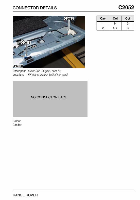
CONNECTOR DETAILS
C2052
Description: Motor-CDL-Tailgate-Lower-RHLocation: RH side of taildoor, behind trim panel
Colour:Gender:
P6968
C2052
C0615
RANGE ROVER
C2052
Cav Col Cct
1 N 32 UY 3

O
C2055 CC2055
Description: ECU-Interlock-Steering columnLocation: Top of steering column
Colour: BLACKGender: Female
P6952
C0278
C2055
NNECTOR DETAILS
Cav Col Cct
1 U 12 B 13 UB 1
5 BU 16 S 17 RY 1
8 WRY 19 NR 1
10 GB 1
11 PB 112 NB 1
RANGE ROVER

CONNECTOR DETAILS
C2057
Description: Module-Passenger doorLocation: Behind passenger's door trim panel
Colour:Gender:
P6895
C2057
C2016
C2059
RANGE ROVER
C2057
Cav Col Cct
1 UR 32 SR 36 W 3
7 B 38 SR 139 NR 3
11 NW 312 U 3

O
C2058 CC2058
Description: Module-Drivers doorLocation: Behind driver's door trim panel
Colour:Gender:
P6890
C2271
C2017
C2186
C2058
C2060
NNECTOR DETAILS
Cav Col Cct
1 UR 32 SR 33 WB 3
4 UR 36 W 37 B 3
8 SR 139 NR 3
11 NW 3
12 U 3
RANGE ROVER

CONNECTOR DETAILS
C2059
Description: Speaker-Mid range-Front door-LHLocation: Behind passenger's door trim panel
Colour:Gender:
P6895
C2057
C2016
C2059
RANGE ROVER
C2059
Cav Col Cct
1 N 282 UY 28

O
C2060 CC2060
Description: Speaker-Mid range-Front door-RHLocation: Behind driver's door trim panel
Colour:Gender:
P6890
C2271
C2017
C2186
C2058
C2060
NNECTOR DETAILS
Cav Col Cct
1 SN 282 SB 28
RANGE ROVER
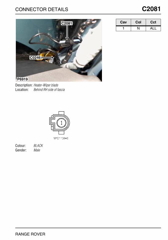
CONNECTOR DETAILS
C2081
Description: Heater-Wiper bladeLocation: Behind RH side of fascia
Colour: BLACKGender: Male
P6919
C0246
C2081
RANGE ROVER
C2081
Cav Col Cct
1 N ALL
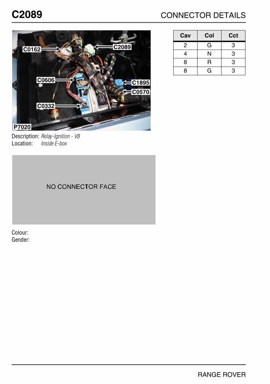
O
C2089 CC2089
Description: Relay-Ignition - V8Location: Inside E-box
Colour:Gender:
P7020
C0162
C0606
C0332
C2089
C1895
C0570
NNECTOR DETAILS
Cav Col Cct
2 G 34 N 38 R 3
8 G 3
RANGE ROVER
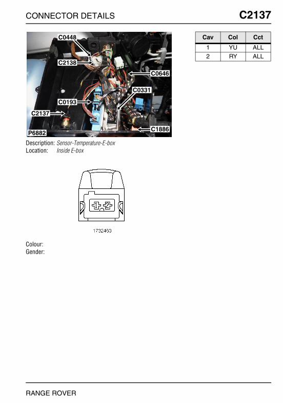
CONNECTOR DETAILS
C2137
Description: Sensor-Temperature-E-boxLocation: Inside E-box
Colour:Gender:
P6882
C0448
C2138
C0193
C0331
C1886
C0646
C2137
RANGE ROVER
C2137
Cav Col Cct
1 YU ALL2 RY ALL
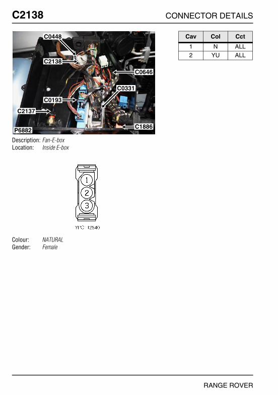
O
C2138 CC2138
Description: Fan-E-boxLocation: Inside E-box
Colour: NATURALGender: Female
P6882
C0448
C2138
C0193
C0331
C1886
C0646
C2137
NNECTOR DETAILS
Cav Col Cct
1 N ALL2 YU ALL
RANGE ROVER
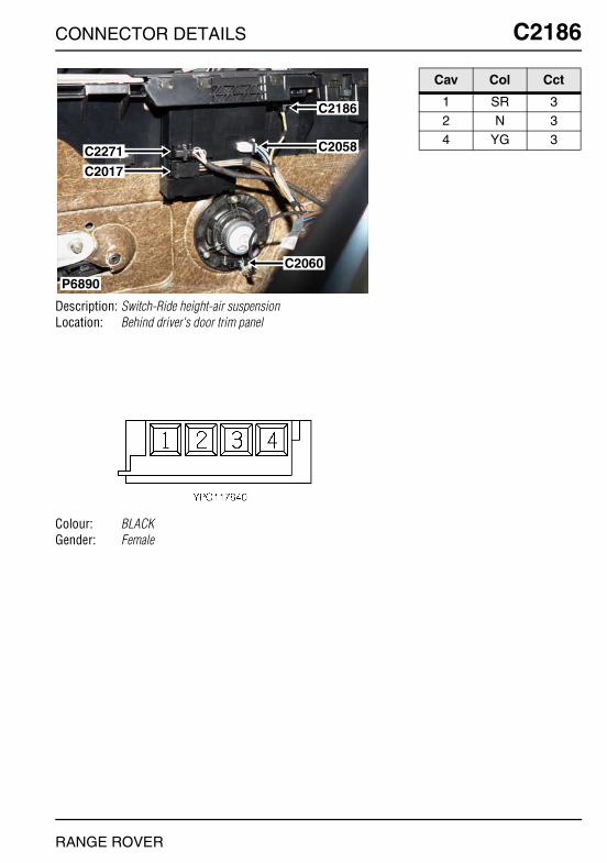
CONNECTOR DETAILS
C2186
Description: Switch-Ride height-air suspensionLocation: Behind driver's door trim panel
Colour: BLACKGender: Female
P6890
C2271
C2017
C2186
C2058
C2060
RANGE ROVER
C2186
Cav Col Cct
1 SR 32 N 34 YG 3
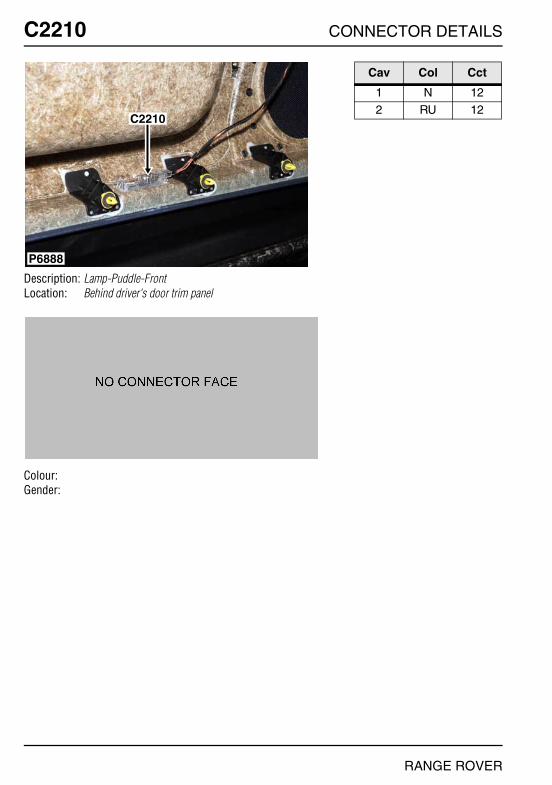
O
C2210 CC2210
Description: Lamp-Puddle-FrontLocation: Behind driver's door trim panel
Colour:Gender:
P6888
C2210
NNECTOR DETAILS
Cav Col Cct
1 N 122 RU 12
RANGE ROVER
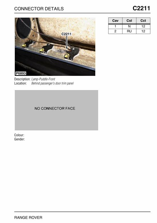
CONNECTOR DETAILS
C2211
Description: Lamp-Puddle-FrontLocation: Behind passenger's door trim panel
Colour:Gender:
P6893
C2211
RANGE ROVER
C2211
Cav Col Cct
1 N 122 RU 12

O
C2212 CC2212
Description: Lamp-Puddle-RearLocation: Behind rear door trim panel
Colour:Gender:
P6904
C0310
C2212
NNECTOR DETAILS
Cav Col Cct
1 N 122 RU 12
RANGE ROVER

CONNECTOR DETAILS
C2262
Description: Actuator-Damping control - Td6Location: Rear LH side of engine
Colour:Gender:
C0169
C2262
P7029
C0191
RANGE ROVER
C2262
Cav Col Cct
1 NP 32 RW 3
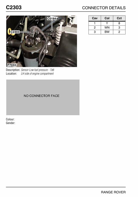
O
C2303 CC2303
Description: Sensor-Low fuel pressure - Td6Location: LH side of engine compartment
Colour:Gender:
P7033
C2303
C0184
NNECTOR DETAILS
Cav Col Cct
1 Y 82 WN 33 BW 2
RANGE ROVER
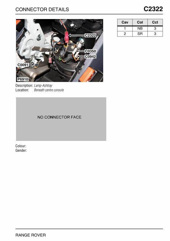
CONNECTOR DETAILS
C2322
Description: Lamp-AshtrayLocation: Beneath centre console
Colour:Gender:
P6910
C0350C0942
C2322
C0091
RANGE ROVER
C2322
Cav Col Cct
1 NB 32 SR 3