RANDALL YDE - nostarch.com
90
6 ARITHMETIC This chapter discusses arithmetic computa- tion in assembly language. By the end of this chapter, you should be able to translate arithmetic expressions and assignment state- ments from high-level languages like Pascal and C/C++ into x86-64 assembly language. 6.1 x86-64 Integer Arithmetic Instructions Before describing how to encode arithmetic expressions in assembly lan- guage, it would be a good idea to first discuss the remaining arithmetic instructions in the x86-64 instruction set. Previous chapters have covered most of the arithmetic and logical instructions, so this section covers the few remaining instructions you’ll need. The Art of 64-Bit Assembly (Sample Chapter) © 6/15/21 by Randall Hyde
Transcript of RANDALL YDE - nostarch.com

6AR ITHMET IC
This chapter discusses arithmetic computa-tion in assembly language. By the end of
this chapter, you should be able to translate arithmetic expressions and assignment state-
ments from high-level languages like Pascal and C/C++ into x86-64 assembly language.
6.1 x86-64 Integer Arithmetic InstructionsBefore describing how to encode arithmetic expressions in assembly lan-guage, it would be a good idea to first discuss the remaining arithmetic instructions in the x86-64 instruction set. Previous chapters have covered most of the arithmetic and logical instructions, so this section covers the few remaining instructions you’ll need.
The Art of 64-Bit Assembly (Sample Chapter) © 6/15/21 by Randall Hyde
T H E A R T O F 6 4 - B I T A S S E M B LY
R A N D A L L H Y D E
6/15/21
288 Chapter 6
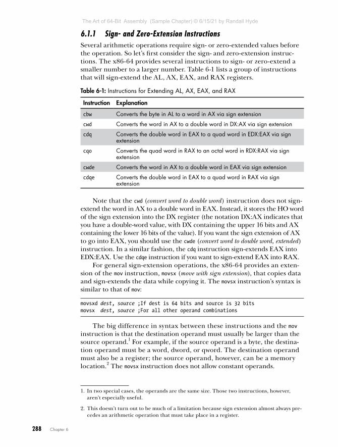
6.1.1 Sign- and Zero-Extension InstructionsSeveral arithmetic operations require sign- or zero-extended values before the operation. So let’s first consider the sign- and zero-extension instruc-tions. The x86-64 provides several instructions to sign- or zero-extend a smaller number to a larger number. Table 6-1 lists a group of instructions that will sign-extend the AL, AX, EAX, and RAX registers.
Table 6-1: Instructions for Extending AL, AX, EAX, and RAX
Instruction Explanation
cbw Converts the byte in AL to a word in AX via sign extension
cwd Converts the word in AX to a double word in DX:AX via sign extension
cdq Converts the double word in EAX to a quad word in EDX:EAX via sign extension
cqo Converts the quad word in RAX to an octal word in RDX:RAX via sign extension
cwde Converts the word in AX to a double word in EAX via sign extension
cdqe Converts the double word in EAX to a quad word in RAX via sign extension
Note that the cwd (convert word to double word) instruction does not sign-extend the word in AX to a double word in EAX. Instead, it stores the HO word of the sign extension into the DX register (the notation DX:AX indicates that you have a double-word value, with DX containing the upper 16 bits and AX containing the lower 16 bits of the value). If you want the sign extension of AX to go into EAX, you should use the cwde (convert word to double word, extended) instruction. In a similar fashion, the cdq instruction sign-extends EAX into EDX:EAX. Use the cdqe instruction if you want to sign-extend EAX into RAX.
For general sign-extension operations, the x86-64 provides an exten-sion of the mov instruction, movsx (move with sign extension), that copies data and sign-extends the data while copying it. The movsx instruction’s syntax is similar to that of mov:
movsxd dest, source ;If dest is 64 bits and source is 32 bitsmovsx dest, source ;For all other operand combinations
The big difference in syntax between these instructions and the mov instruction is that the destination operand must usually be larger than the source operand.1 For example, if the source operand is a byte, the destina-tion operand must be a word, dword, or qword. The destination operand must also be a register; the source operand, however, can be a memory location.2 The movsx instruction does not allow constant operands.
1. In two special cases, the operands are the same size. Those two instructions, however, aren’t especially useful.
2. This doesn’t turn out to be much of a limitation because sign extension almost always pre-cedes an arithmetic operation that must take place in a register.
The Art of 64-Bit Assembly (Sample Chapter) © 6/15/21 by Randall Hyde
T H E A R T O F 6 4 - B I T A S S E M B LY
R A N D A L L H Y D E
6/15/21

Arithmetic 289
For whatever reason, MASM requires a different instruction mnemonic (instruction name) when sign-extending a 32-bit operand into a 64-bit reg-ister (movsxd rather than movsx).
To zero-extend a value, you can use the movzx instruction. It does not have the restrictions of movsx; as long as the destination operand is larger than the source operand, the instruction works fine. It allows 8 to 16, 32, or 64 bits, and 16 to 32 or 64 bits. There is no 32- to 64-bit version (it turns out this is unnecessary).
The x86-64 CPUs, for historical reasons, will always zero-extend a regis-ter from 32 bits to 64 bits when performing 32-bit operations. Therefore, to zero-extend a 32-bit register into a 64-bit register, you need only move the (32-bit) register into itself; for example:
mov eax, eax ;zero-extends EAX into RAX
Zero-extending certain 8-bit registers (AL, BL, CL, and DL) into their corresponding 16-bit registers is easily accomplished without using movzx by loading the complementary HO register (AH, BH, CH, or DH) with 0. To zero-extend AX into DX:AX or EAX into EDX:EAX, all you need to do is load DX or EDX with 0.3
Because of instruction-encoding limitations, the x86-64 does not allow you to zero- or sign-extend the AH, BH, CH, or DH registers into any of the 64-bit registers.
6.1.2 The mul and imul InstructionsYou’ve already seen a subset of the imul instructions available in the x86-64 instruction set (see “The imul Instruction” in Chapter 4). This section presents the extended-precision version of imul along with the unsigned mul instruction.
The multiplication instructions provide you with another taste of irregularity in the x86-64’s instruction set. Instructions like add, sub, and many others in the x86-64 instruction set support two operands, just like the mov instruction. Unfortunately, there weren’t enough bits in the origi-nal 8086 opcode byte to support all instructions, so the x86-64 treats the mul (unsigned multiply) and imul (signed integer multiply) instructions as single-operand instructions, just like the inc, dec, and neg instructions. Of course, multiplication is a two-operand function. To work around this fact, the x86-64 always assumes the accumulator (AL, AX, EAX, or RAX) is the destination operand.
Another problem with the mul and imul instructions is that you cannot use them to multiply the accumulator by a constant. Intel quickly discovered the need to support multiplication by a constant and added the more gen-eral versions of the imul instruction to overcome this problem. Nevertheless, you must be aware that the basic mul and imul instructions do not support the full range of operands as the imul appearing in Chapter 4.
3. Zero-extending into DX:AX or EDX:EAX is just as necessary as the cwd and cdq instruc-tions, as you will eventually see.
The Art of 64-Bit Assembly (Sample Chapter) © 6/15/21 by Randall Hyde
T H E A R T O F 6 4 - B I T A S S E M B LY
R A N D A L L H Y D E
6/15/21

290 Chapter 6
The multiply instruction has two forms: unsigned multiplication (mul) and signed multiplication (imul). Unlike addition and subtraction, you need separate instructions for signed and unsigned operations.
The single-operand multiply instructions take the following forms:Unsigned multiplication:
mul reg8 ;returns AXmul reg16 ; returns DX:AXmul reg32 ; returns EDX:EAXmul reg64 ; returns RDX:RAX
mul mem8 ; returns AXmul mem16 ; returns DX:AXmul mem32 ; returns EDX:EAXmul mem64 ; returns RDX:RAX
Signed (integer) multiplication:
imul reg8 ; returns AXimul reg16 ; returns DX:AXimul reg32 ; returns EDX:EAXimul reg64 ; returns RDX:RAX
imul mem8 ; returns AXimul mem16 ; returns DX:AXimul mem32 ; returns EDX:EAXimul mem64 ; returns RDX:RAX
When multiplying two n -bit values, the result may require as many as 2 × n bits. Therefore, if the operand is an 8-bit quantity, the result could require 16 bits. Likewise, a 16-bit operand produces a 32-bit result, a 32-bit operand produces 64 bits, and a 64-bit operand requires as many as 128 bits to hold the result. Table 6-2 lists the various computations.
Table 6-2: mul and imul Operations
Instruction Computes
mul operand8 AX = AL × operand8 (unsigned)
imul operand8 AX = AL × operand8 (signed)
mul operand16 DX:AX = AX × operand16 (unsigned)
imul operand16 DX:AX = AX × operand16 (signed)
mul operand32 EDX:EAX = EAX × operand32 (unsigned)
imul operand32 EDX:EAX = EAX × operand32 (signed)
mul operand64 RDX:RAX = RAX × operand64 (unsigned)
imul operand64 RDX:RAX = RAX × operand64 (signed)
If an 8×8-, 16×16-, 32×32-, or 64×64-bit product requires more than 8, 16, 32, or 64 bits (respectively), the mul and imul instructions set the carry and overflow flags. mul and imul scramble the sign and zero flags.
The Art of 64-Bit Assembly (Sample Chapter) © 6/15/21 by Randall Hyde
T H E A R T O F 6 4 - B I T A S S E M B LY
R A N D A L L H Y D E
6/15/21

Arithmetic 291
NO T E The sign and zero flags do not contain meaningful values after the execution of these two instructions.
You’ll use the single-operand mul and imul instructions quite a lot when you learn about extended-precision arithmetic in Chapter 8. Unless you’re doing multiprecision work, however, you’ll probably want to use the more generic multi-operand version of the imul instruction in place of the extended-precision mul or imul. However, the generic imul (see Chapter 4) is not a complete replacement for these two instructions; in addition to the number of operands, several differences exist. The following rules apply specifically to the generic (multi-operand) imul instruction:
• There isn’t an 8×8-bit multi-operand imul instruction available.
• The generic imul instruction does not produce a 2n-bit result, but trun-cates the result to n bits. That is, a 16×16bit multiplication produces a 16-bit result. Likewise, a 32×32-bit multiplication produces a 32-bit result. These instructions set the carry and overflow flags if the result does not fit into the destination register.
6.1.3 The div and idiv InstructionsThe x86-64 divide instructions perform a 128/64-bit division, a 64/32-bit division, a 32/16-bit division, or a 16/8-bit division. These instructions take the following forms:
div reg8div reg16div reg32div reg64
div mem8div mem16div mem32div mem64
idiv reg8idiv reg16idiv reg32idiv reg64
idiv mem8idiv mem16idiv mem32idiv mem64
The div instruction is an unsigned division operation. If the operand is an 8-bit operand, div divides the AX register by the operand, leaving the quotient in AL and the remainder (modulo) in AH. If the operand is a 16-bit quantity, the div instruction divides the 32-bit quantity in DX:AX by the operand, leaving the quotient in AX and the remainder in DX. With
The Art of 64-Bit Assembly (Sample Chapter) © 6/15/21 by Randall Hyde
T H E A R T O F 6 4 - B I T A S S E M B LY
R A N D A L L H Y D E
6/15/21

292 Chapter 6
32-bit operands, div divides the 64-bit value in EDX:EAX by the operand, leaving the quotient in EAX and the remainder in EDX. Finally, with 64-bit operands, div divides the 128-bit value in RDX:RAX by the operand, leav-ing the quotient in RAX and the remainder in RDX.
There is no variant of the div or idiv instructions that allows you to divide a value by a constant. If you want to divide a value by a constant, you need to create a memory object (preferably in the .const section) that is ini-tialized with the constant, and then use that memory value as the div/idiv operand. For example:
.constten dword 10 . . . div ten ;Divides EDX:EAX by 10
The idiv instruction computes a signed quotient and remainder. The syntax for the idiv instruction is identical to div (except for the use of the idiv mnemonic), though creating signed operands for idiv may require a different sequence of instructions prior to executing idiv than for div.
You cannot, on the x86-64, simply divide one unsigned 8-bit value by another. If the denominator is an 8-bit value, the numerator must be a 16-bit value. If you need to divide one unsigned 8-bit value by another, you must zero-extend the numerator to 16 bits by loading the numerator into the AL register and then moving 0 into the AH register. Failing to zero-extend AL before executing div may cause the x86-64 to produce incorrect results! When you need to divide two 16-bit unsigned values, you must zero-extend the AX register (which contains the numerator) into the DX register. To do this, just load 0 into the DX register. If you need to divide one 32-bit value by another, you must zero-extend the EAX register into EDX (by loading a 0 into EDX) before the division. Finally, to divide one 64-bit number by another, you must zero-extend RAX into RDX (for example, using an xor rdx, rdx instruction) prior to the division.
When dealing with signed integer values, you will need to sign-extend AL into AX, AX into DX, EAX into EDX, or RAX into RDX before execut-ing idiv. To do so, use the cbw, cwd, cdq, or cqo instructions.4 Failure to do so may produce incorrect results.
The x86-64’s divide instructions have one other issue: you can get a fatal error when using this instruction. First, of course, you can attempt to divide a value by 0. Another problem is that the quotient may be too large to fit into the RAX, EAX, AX, or AL register. For example, the 16/8-bit division 8000h/2 produces the quotient 4000h with a remainder of 0. 4000h will not fit into 8 bits. If this happens, or you attempt to divide by 0, the x86-64 will generate a division exception or integer overflow exception. This usu-ally means your program will crash. If this happens to you, chances are you
4. You could also use movsx to sign-extend AL into AX.
The Art of 64-Bit Assembly (Sample Chapter) © 6/15/21 by Randall Hyde
T H E A R T O F 6 4 - B I T A S S E M B LY
R A N D A L L H Y D E
6/15/21

Arithmetic 293
didn’t sign- or zero-extend your numerator before executing the division operation. Because this error may cause your program to crash, you should be very careful about the values you select when using division.
The x86-64 leaves the carry, overflow, sign, and zero flags undefined after a division operation. Therefore, you cannot test for problems after a division operation by checking the flag bits.
6.1.4 The cmp Instruction, RevisitedAs noted in “The cmp Instruction and Corresponding Conditional Jumps” in Chapter 2, the cmp instruction updates the x86-64’s flags according to the result of the subtraction operation (leftOperand - rightOperand). The x86-64 sets the flags in an appropriate fashion so that we can read this instruction as “compare leftOperand to rightOperand.” You can test the result of the com-parison by using the conditional set instructions to check the appropriate flags in the flags register (see “The setcc Instructions” on page xx) or the conditional jump instructions (Chapter 2 or Chapter 7).
Probably the first place to start when exploring the cmp instruction is to look at exactly how it affects the flags. Consider the following cmp instruction:
cmp ax, bx
This instruction performs the computation AX – BX and sets the flags depending on the result of the computation. The flags are set as follows (also see Table 6-3):
ZF
The zero flag is set if and only if AX = BX. This is the only time AX – BX produces a 0 result. Hence, you can use the zero flag to test for equality or inequality.
SF
The sign flag is set to 1 if the result is negative. At first glance, you might think that this flag would be set if AX is less than BX, but this isn’t always the case. If AX = 7FFFh and BX = –1 (0FFFFh), then subtracting AX from BX produces 8000h, which is negative (and so the sign flag will be set). So, for signed comparisons anyway, the sign flag doesn’t contain the proper status. For unsigned operands, consider AX = 0FFFFh and BX = 1. Here, AX is greater than BX but their difference is 0FFFEh, which is still negative. As it turns out, the sign flag and the overflow flag, taken together, can be used for comparing two signed values.
OF
The overflow flag is set after a cmp operation if the difference of AX and BX produced an overflow or underflow. As mentioned previously, the sign and overflow flags are both used when performing signed comparisons.
The Art of 64-Bit Assembly (Sample Chapter) © 6/15/21 by Randall Hyde
T H E A R T O F 6 4 - B I T A S S E M B LY
R A N D A L L H Y D E
6/15/21

294 Chapter 6
CF
The carry flag is set after a cmp operation if subtracting BX from AX requires a borrow. This occurs only when AX is less than BX, where AX and BX are both unsigned values.
Table 6-3: Condition Code Settings After cmp
Unsigned operands Signed operands
ZF: Equality/inequality ZF: Equality/inequality
CF: Left < Right (C = 1) Left >= Right (C = 0)
CF: No meaning
SF: No meaning SF: See discussion in this section
OF: No meaning O:F See discussion in this section
Given that the cmp instruction sets the flags in this fashion, you can test the comparison of the two operands with the following flags:
cmp Left, Right
For signed comparisons, the SF (sign) and OF (overflow) flags, taken together, have the following meanings:
• If [(SF = 0) and (OF = 1)] or [(SF = 1) and (OF = 0)], then Left < Right for a signed comparison.
• If [(SF = 0) and (OF = 0)] or [(SF = 1) and (OF = 1)], then Left >= Right for a signed comparison.
Note that (SF xor OF) is 1 if the left operand is less than the right oper-and. Conversely, (SF xor OF) is 0 if the left operand is greater or equal to the right operand.
To understand why these flags are set in this manner, consider the examples in Table 6-4.
Table 6-4: Sign and Overflow Flag Settings After Subtraction
Left Minus Right SF OF
0FFFFh (–1) – 0FFFEh (–2) 0 0
8000h (–32,768) – 0001h 0 1
0FFFEh (–2) – 0FFFFh (–1) 1 0
7FFFh (32767) – 0FFFFh (–1) 1 1
Remember, the cmp operation is really a subtraction; therefore, the first example in Table 6-4 computes (–1) – (–2), which is (+1). The result is posi-tive and an overflow did not occur, so both the S and O flags are 0. Because (SF xor OF) is 0, Left is greater than or equal to Right.
The Art of 64-Bit Assembly (Sample Chapter) © 6/15/21 by Randall Hyde
T H E A R T O F 6 4 - B I T A S S E M B LY
R A N D A L L H Y D E
6/15/21

Arithmetic 295
In the second example, the cmp instruction would compute (–32,768) – (+1), which is (–32,769). Because a 16-bit signed integer cannot represent this value, the value wraps around to 7FFFh (+32,767) and sets the overflow flag. The result is positive (at least as a 16-bit value), so the CPU clears the sign flag. (SF xor OF) is 1 here, so Left is less than Right.
In the third example, cmp computes (–2) – (–1), which produces (–1). No overflow occurred, so the OF is 0, the result is negative, so the SF is 1. Because (SF xor OF) is 1, Left is less than Right.
In the fourth (and final) example, cmp computes (+32,767) – (–1). This produces (+32,768), setting the overflow flag. Furthermore, the value wraps around to 8000h (–32,768), so the sign flag is set as well. Because (SF xor OF) is 0, Left is greater than or equal to Right.
6.1.5 The setcc InstructionsThe setcc (set on condition) instructions set a single-byte operand (register or memory) to 0 or 1 depending on the values in the flags register. The gen-eral formats for the setcc instructions are as follows:
setcc reg8setcc mem8
setcc represents a mnemonic appearing in Tables 6-5, 6-6, and 6-7. These instructions store a 0 in the corresponding operand if the condition is false, and they store a 1 in the 8-bit operand if the condition is true.
Table 6-5: setcc Instructions That Test Flags
Instruction Description Condition Comments
setc Set if carry Carry = 1 Same as setb, setnae
setnc Set if no carry Carry = 0 Same as setnb, setae
setz Set if zero Zero = 1 Same as sete
setnz Set if not zero Zero = 0 Same as setne
sets Set if sign Sign = 1
setns Set if no sign Sign = 0
seto Set if overflow Overflow = 1
setno Set if no overflow Overflow = 0
setp Set if parity Parity = 1 Same as setpe
setpe Set if parity even Parity = 1 Same as setp
setnp Set if no parity Parity = 0 Same as setpo
setpo Set if parity odd Parity = 0 Same as setnp
The Art of 64-Bit Assembly (Sample Chapter) © 6/15/21 by Randall Hyde
T H E A R T O F 6 4 - B I T A S S E M B LY
R A N D A L L H Y D E
6/15/21

296 Chapter 6
The setcc instructions in Table 6-5 simply test the flags without any other meaning attached to the operation. You could, for example, use setc to check the carry flag after a shift, rotate, bit test, or arithmetic operation.
The setp/setpe and setnp/setpo instructions check the parity flag. These instructions appear here for completeness, but this book will not spend much time discussing the parity flag; in modern code, it’s typically used only to check for an FPU not-a-number (NaN) condition.
The cmp instruction works synergistically with the setcc instructions. Immediately after a cmp operation, the processor flags provide information concerning the relative values of those operands. They allow you to see if one operand is less than, equal to, or greater than the other.
Two additional groups of setcc instructions are useful after a cmp operation. The first group deals with the result of an unsigned comparison (Table 6-6); the second group deals with the result of a signed comparison (Table 6-7).
Table 6-6: setcc Instructions for Unsigned Comparisons
Instruction Description Condition Comments
seta Set if above (>) Carry = 0, Zero = 0 Same as setnbe
setnbe Set if not below or equal (not <=)
Carry = 0, Zero = 0 Same as seta
setae Set if above or equal (>=)
Carry = 0 Same as setnc, setnb
setnb Set if not below (not <)
Carry = 0 Same as setnc, setae
setb Set if below (<) Carry = 1 Same as setc, setnae
setnae Set if not above or equal (not >=)
Carry = 1 Same as setc, setb
setbe Set if below or equal (<=)
Carry = 1 or Zero = 1
Same as setna
setna Set if not above (not >)
Carry = 1 or Zero = 1
Same as setbe
sete Set if equal (==) Zero = 1 Same as setz
setne Set if not equal (!=) Zero = 0 Same as setnz
Table 6-7: setcc Instructions for Signed Comparisons
Instruction Description Condition Comments
setg Set if greater (>) Sign == Overflow and Zero == 0
Same as setnle
setnle Set if not less than or equal (not <=)
Sign == Overflow or Zero == 0
Same as setg
The Art of 64-Bit Assembly (Sample Chapter) © 6/15/21 by Randall Hyde
T H E A R T O F 6 4 - B I T A S S E M B LY
R A N D A L L H Y D E
6/15/21

Arithmetic 297
Instruction Description Condition Comments
setge Set if greater than or equal (>=)
Sign == Overflow Same as setnl
setnl Set if not less than (not <)
Sign == Overflow Same as setge
setl Set if less than (<) Sign != Overflow Same as setnge
setnge Set if not greater or equal (not >=)
Sign != Overflow Same as setl
setle Set if less than or equal (<=)
Sign != Overflow or Zero == 1
Same as setng
setng Set if not greater than (not >)
Sign != Overflow or Zero == 1
Same as setle
sete Set if equal (=) Zero == 1 Same as setz
setne Set if not equal (!=) Zero == 0 Same as setnz
The setcc instructions are particularly valuable because they can con-vert the result of a comparison to a Boolean value (false/true or 0/1). This is especially important when translating statements from a high-level lan-guage like Swift or C/C++ into assembly language. The following example shows how to use these instructions in this manner:
; bool = a <= b
mov eax, a cmp eax, b setle bool ; bool is a byte variable.
Because the setcc instructions always produce 0 or 1, you can use the results with the and and or instructions to compute complex Boolean values:
; bool = ((a <= b) && (d == e))
mov eax, a cmp eax, b setle bl mov eax, d cmp eax, e sete bh and bh, bl mov bool, bh
6.1.6 The test InstructionThe x86-64 test instruction is to the and instruction what the cmp instruction is to sub. That is, the test instruction computes the logical AND of its two operands and sets the condition code flags based on the result; it does not,
The Art of 64-Bit Assembly (Sample Chapter) © 6/15/21 by Randall Hyde
T H E A R T O F 6 4 - B I T A S S E M B LY
R A N D A L L H Y D E
6/15/21

298 Chapter 6
however, store the result of the logical AND back into the destination oper-and. The syntax for the test instruction is similar to and:
test operand1, operand2
The test instruction sets the zero flag if the result of the logical AND operation is 0. It sets the sign flag if the HO bit of the result contains a 1. The test instruction always clears the carry and overflow flags.
The primary use of the test instruction is to check whether an indi-vidual bit contains a 0 or a 1. Consider the instruction test al, 1. This instruction logically ANDs AL with the value 1; if bit 1 of AL contains 0, the result will be 0 (setting the zero flag) because all the other bits in the con-stant 1 are 0. Conversely, if bit 1 of AL contains 1, then the result is not 0, so test clears the zero flag. Therefore, you can test the zero flag after this test instruction to see if bit 0 contains a 0 or a 1 (for example, using setz or setnz instructions, or the jz/jnz instructions).
The test instruction can also check whether all the bits in a specified set of bits contain 0. The instruction test al, 0fh sets the zero flag if and only if the LO 4 bits of AL all contain 0.
One important use of the test instruction is to check whether a register contains 0. The instruction test reg, reg, where both operands are the same register, will logically AND that register with itself. If the register contains 0, the result is 0 and the CPU will set the zero flag. However, if the register contains a nonzero value, logically ANDing that value with itself produces that same nonzero value, so the CPU clears the zero flag. Therefore, you can check the zero flag immediately after the execution of this instruction (for example, using the setz or setnz instructions or the jz and jnz instruc-tions) to see if the register contains 0. Here are some examples:
test eax, eax setz bl ; bl is set to 1 if EAX contains 0. . . . test bl, bl jz bxIs0
Do something if bl != 0
bxIs0:
One major failing of the test instruction is that immediate (constant) operands can be no larger than 32 bits (as is the case with most instruc-tions), which makes it difficult to use this instruction to test for set bits beyond bit position 31. For testing individual bits, you can use the bt (bit test) instruction (see “Instructions That Manipulate Bits” in Chapter 12). Otherwise, you’ll have to move the 64-bit constant into a register (the mov instruction does support 64-bit immediate operands) and then test your target register against the 64-bit constant value in the newly loaded register.
The Art of 64-Bit Assembly (Sample Chapter) © 6/15/21 by Randall Hyde
T H E A R T O F 6 4 - B I T A S S E M B LY
R A N D A L L H Y D E
6/15/21

Arithmetic 299
6.2 Arithmetic ExpressionsProbably the biggest shock to beginners facing assembly language for the first time is the lack of familiar arithmetic expressions. Arithmetic expressions, in most high-level languages, look similar to their algebraic equivalents. For example:
x = y * z;
In assembly language, you’ll need several statements to accomplish this same task:
mov eax, yimul eax, zmov x, eax
Obviously, the HLL version is much easier to type, read, and understand. Although a lot of typing is involved, converting an arithmetic expression into assembly language isn’t difficult at all. By attacking the problem in steps, the same way you would solve the problem by hand, you can easily break any arithmetic expression into an equivalent sequence of assembly language statements.
6.2.1 Simple AssignmentsThe easiest expressions to convert to assembly language are simple assign-ments. Simple assignments copy a single value into a variable and take one of two forms:
variable = constant
or
var1 = var2
Converting the first form to assembly language is simple—just use this assembly language statement:
mov variable, constant
This mov instruction copies the constant into the variable.The second assignment is slightly more complicated because the x86-64
doesn’t provide a memory-to-memory mov instruction. Therefore, to copy one memory variable into another, you must move the data through a reg-ister. By convention (and for slight efficiency reasons), most programmers tend to favor AL/AX/EAX/RAX for this purpose. For example:
var1 = var2;
becomes
mov eax, var2mov var1, eax
The Art of 64-Bit Assembly (Sample Chapter) © 6/15/21 by Randall Hyde
T H E A R T O F 6 4 - B I T A S S E M B LY
R A N D A L L H Y D E
6/15/21

300 Chapter 6
assuming that var1 and var2 are 32-bit variables. Use AL if they are 8-bit variables; use AX if they are 16-bit variables, or use RAX if they are 64-bit variables.
Of course, if you’re already using AL, AX, EAX, or RAX for something else, one of the other registers will suffice. Regardless, you will generally use a register to transfer one memory location to another.
6.2.2 Simple ExpressionsThe next level of complexity is a simple expression. A simple expression takes the following form:
var1 = term1 op term2;
var1 is a variable, term1 and term2 are variables or constants, and op is an arithmetic operator (addition, subtraction, multiplication, and so on). Most expressions take this form. It should come as no surprise, then, that the x86-64 architecture was optimized for just this type of expression.
A typical conversion for this type of expression takes the following form:
mov eax, term1op eax, term2mov var1, eax
op is the mnemonic that corresponds to the specified operation (for example, + is add, – is sub, and so forth).
Note that the simple expression var1 = const1 op const2; is easily handled with a compile-time expression and a single mov instruction. For example, to compute var1 = 5 + 3;,use the single instruction mov var1, 5 + 3.
You need to be aware of a few inconsistencies. When dealing with the (i)mul and (i)div instructions on the x86-64, you must use the AL/AX/EAX/ RAX and AH/DX/EDX/RDX registers. You cannot use arbitrary registers as you can with other operations. Also, don’t forget the sign-extension instruc-tions if you’re performing a division operation to divide one 16/32/64-bit number by another. Finally, don’t forget that some instructions may cause overflow. You may want to check for an overflow (or underflow) condition after an arithmetic operation.
Here are examples of common simple expressions:
;x = y + z;
mov eax, y add eax, z mov x, eax
;x = y - z;
mov eax, y
The Art of 64-Bit Assembly (Sample Chapter) © 6/15/21 by Randall Hyde
T H E A R T O F 6 4 - B I T A S S E M B LY
R A N D A L L H Y D E
6/15/21

Arithmetic 301
sub eax, z mov x, eax
;x = y * z; {unsigned}
mov eax, y mul z ; Don't forget this wipes out EDX. mov x, eax
;x = y * z; {signed}
mov eax, y imul eax, z ; Does not affect EDX! mov x, eax
;x = y div z; {unsigned div}
mov eax, y xor edx, edx ; Zero-extend EAX into EDX. div z mov x, eax
;x = y idiv z; {signed div}
mov eax, y cdq ; Sign-extend EAX into EDX. idiv z mov x, eax
;x = y % z; {unsigned remainder}
mov eax, y xor edx, edx ; Zero-extend EAX into EDX. div z mov x, edx ; Note that remainder is in EDX.
;x = y % z; {signed remainder}
mov eax, y cdq ; Sign-extend EAX into EDX. idiv z mov x, edx ; Remainder is in EDX.
Certain unary operations also qualify as simple expressions, producing additional inconsistencies to the general rule. A good example of a unary operation is negation. In a high-level language, negation takes one of two possible forms:
var = –var
or
var1 = –var2
The Art of 64-Bit Assembly (Sample Chapter) © 6/15/21 by Randall Hyde
T H E A R T O F 6 4 - B I T A S S E M B LY
R A N D A L L H Y D E
6/15/21

302 Chapter 6
Note that var = –constant is really a simple assignment, not a simple expression. You can specify a negative constant as an operand to the mov instruction:
mov var, -14
To handle var1 = –var1, use this single assembly language statement:
; var1 = -var1;
neg var1
If two different variables are involved, use the following:
; var1 = -var2;
mov eax, var2neg eaxmov var1, eax
6.2.3 Complex ExpressionsA complex expression is any arithmetic expression involving more than two terms and one operator. Such expressions are commonly found in programs written in a high-level language. Complex expressions may include paren-theses to override operator precedence, function calls, array accesses, and so on. This section outlines the rules for converting such expressions.
A complex expression that is easy to convert to assembly language is one that involves three terms and two operators. For example:
w = w - y - z;
Clearly the straightforward assembly language conversion of this state-ment requires two sub instructions. However, even with an expression as simple as this, the conversion is not trivial. There are actually two ways to convert the preceding statement into assembly language:
mov eax, wsub eax, ysub eax, zmov w, eax
and
mov eax, ysub eax, zsub w, eax
The second conversion, because it is shorter, looks better. However, it produces an incorrect result (assuming C-like semantics for the original state-ment). Associativity is the problem. The second sequence in the preceding example computes w = w – (y – z), which is not the same as w = (w – y) – z.
The Art of 64-Bit Assembly (Sample Chapter) © 6/15/21 by Randall Hyde
T H E A R T O F 6 4 - B I T A S S E M B LY
R A N D A L L H Y D E
6/15/21

Arithmetic 303
How we place the parentheses around the subexpressions can affect the result. Note that if you are interested in a shorter form, you can use the fol-lowing sequence:
mov eax, yadd eax, zsub w, eax
This computes w = w – (y + z), equivalent to w = (w – y) – z.Precedence is another issue. Consider this expression:
x = w * y + z;
Once again, we can evaluate this expression in two ways:
x = (w * y) + z;
or
x = w * (y + z);
By now, you’re probably thinking that this explanation is crazy. Everyone knows the correct way to evaluate these expressions is by the former form. However, you’d be wrong. The APL programming language, for example, evaluates expressions solely from right to left and does not give one operator precedence over another. Which way is “correct” depends entirely on how you define precedence in your arithmetic system.
Consider this expression:
x op1 y op2 z
If op1 takes precedence over op2, then this evaluates to (x op1 y) op2 z. Otherwise, if op2 takes precedence over op1, this evaluates to x op1 (y op2 z). Depending on the operators and operands involved, these two computa-tions could produce different results.
Most high-level languages use a fixed set of precedence rules to describe the order of evaluation in an expression involving two or more different operators. Such programming languages usually compute multiplication and division before addition and subtraction. Those that support exponen-tiation (for example, FORTRAN and BASIC) usually compute that before multiplication and division. These rules are intuitive because almost every-one learns them before high school.
When converting expressions into assembly language, you must be sure to compute the subexpression with the highest precedence first. The follow-ing example demonstrates this technique:
; w = x + y * z;
mov ebx, x mov eax, y ; Must compute y * z first because "*" imul eax, z ; has higher precedence than "+".
The Art of 64-Bit Assembly (Sample Chapter) © 6/15/21 by Randall Hyde
T H E A R T O F 6 4 - B I T A S S E M B LY
R A N D A L L H Y D E
6/15/21

304 Chapter 6
add eax, ebx mov w, eax
If two operators appearing within an expression have the same pre-cedence, you determine the order of evaluation by using associativity rules. Most operators are left-associative, meaning that they evaluate from left to right. Addition, subtraction, multiplication, and division are all left-associative. A right-associative operator evaluates from right to left. The exponentiation oper-ator in FORTRAN is a good example of a right-associative operator:
2**2**3
is equal to
2**(2**3)
not
(2**2)**3
The precedence and associativity rules determine the order of evaluation. Indirectly, these rules tell you where to place parentheses in an expression to determine the order of evaluation. Of course, you can always use parentheses to override the default precedence and associativity. However, the ultimate point is that your assembly code must complete certain operations before others to correctly compute the value of a given expression. The following examples demonstrate this principle:
; w = x - y - z
mov eax, x ; All the same operator precedence, sub eax, y ; so we need to evaluate from left sub eax, z ; to right because they are left- mov w, eax ; associative.
; w = x + y * z
mov eax, y ; Must compute y * z first because imul eax, z ; multiplication has a higher add eax, x ; precedence than addition. mov w, eax
; w = x / y - z
mov eax, x ; Here we need to compute division cdq ; first because it has the highest idiv y ; precedence. sub eax, z mov w, eax
; w = x * y * z
The Art of 64-Bit Assembly (Sample Chapter) © 6/15/21 by Randall Hyde
T H E A R T O F 6 4 - B I T A S S E M B LY
R A N D A L L H Y D E
6/15/21

Arithmetic 305
mov eax, y ; Addition and multiplication are imul eax, z ; commutative; therefore, the order imul eax, x ; of evaluation does not matter. mov w, eax
The associativity rule has one exception: if an expression involves mul-tiplication and division, it is generally better to perform the multiplication first. For example, given an expression of the form
w = x / y * z ; Note: This is (x * z) / y, not x / (y * z).
it is usually better to compute x * z and then divide the result by y rather than divide x by y and multiply the quotient by z.
This approach is better for two reasons. First, remember that the imul instruction always produces a 64-bit result (assuming 32-bit operands). By doing the multiplication first, you automatically sign-extend the product into the EDX register so you do not have to sign-extend EAX prior to the division.
A second reason for doing the multiplication first is to increase the accuracy of the computation. Remember, (integer) division often produces an inexact result. For example, if you compute 5 / 2, you will get the value 2, not 2.5. Computing (5 / 2) × 3 produces 6. However, if you compute (5 × 3) / 2, you get the value 7, which is a little closer to the real quotient (7.5). Therefore, if you encounter an expression of the form
w = x / y * z;
you can usually convert it to the following assembly code:
mov eax, ximul z ; Note the use of extended imul!idiv ymov w, eax
If the algorithm you’re encoding depends on the truncation effect of the division operation, you cannot use this trick to improve the algorithm. Moral of the story: always make sure you fully understand any expression you are converting to assembly language. If the semantics dictate that you must perform the division first, then do so.
Consider the following statement:
w = x – y * x;
Because subtraction is not commutative, you cannot compute y * x and then subtract x from this result. Rather than use a straightforward multipli-cation-and-addition sequence, you’ll have to load x into a register, multiply y and x, leaving their product in a different register, and then subtract this product from x. For example:
mov ecx, xmov eax, y
The Art of 64-Bit Assembly (Sample Chapter) © 6/15/21 by Randall Hyde
T H E A R T O F 6 4 - B I T A S S E M B LY
R A N D A L L H Y D E
6/15/21

306 Chapter 6
imul eax, xsub ecx, eaxmov w, ecx
This trivial example demonstrates the need for temporary variables in an expression. The code uses the ECX register to temporarily hold a copy of x until it computes the product of y and x. As your expressions increase in complexity, the need for temporaries grows. Consider the following C statement:
w = (a + b) * (y + z);
Following the normal rules of algebraic evaluation, you compute the subexpressions inside the parentheses first (that is, the two subexpressions with the highest precedence) and set their values aside. When you’ve com-puted the values for both subexpressions, you can compute their product. One way to deal with a complex expression like this is to reduce it to a sequence of simple expressions whose results wind up in temporary vari-ables. For example, you can convert the preceding single expression into the following sequence:
temp1 = a + b;temp2 = y + z;w = temp1 * temp2;
Because converting simple expressions to assembly language is quite easy, it’s now a snap to compute the former complex expression in assembly. The code is shown here:
mov eax, aadd eax, bmov temp1, eaxmov eax, yadd eax, zmov temp2, eaxmov eax, temp1imul eax, temp2mov w, eax
This code is grossly inefficient and requires that you declare a couple of temporary variables in your data segment. However, it is easy to optimize this code by keeping temporary variables, as much as possible, in x86-64 registers. By using x86-64 registers to hold the temporary results, this code becomes the following:
mov eax, aadd eax, bmov ebx, yadd ebx, zimul eax, ebxmov w, eax
The Art of 64-Bit Assembly (Sample Chapter) © 6/15/21 by Randall Hyde
T H E A R T O F 6 4 - B I T A S S E M B LY
R A N D A L L H Y D E
6/15/21

Arithmetic 307
Here’s yet another example:
x = (y + z) * (a - b) / 10;
This can be converted to a set of four simple expressions:
temp1 = (y + z)temp2 = (a - b)temp1 = temp1 * temp2x = temp1 / 10
You can convert these four simple expressions into the following assem-bly language statements:
.constten dword 10 . . . mov eax, y ; Compute EAX = y + z add eax, z mov ebx, a ; Compute EBX = a - b sub ebx, b imul ebx ; This sign-extends EAX into EDX. idiv ten mov x, eax
The most important thing to keep in mind is that you should keep tem-porary values in registers for efficiency. Use memory locations to hold tempo-raries only if you’ve run out of registers.
Ultimately, converting a complex expression to assembly language is a little different from solving the expression by hand. Instead of actually computing the result at each stage of the computation, you simply write the assembly code that computes the result.
6.2.4 Commutative OperatorsIf op represents an operator, that operator is commutative if the following relationship is always true:
(A op B) = (B op A)
As you saw in the previous section, commutative operators are nice because the order of their operands is immaterial, and this lets you rear-range a computation, often making it easier or more efficient. Often, rearranging a computation allows you to use fewer temporary variables. Whenever you encounter a commutative operator in an expression, you should always check whether you can use a better sequence to improve the size or speed of your code.
Tables 6-8 and 6-9, respectively, list the commutative and noncommuta-tive operators you typically find in high-level languages.
The Art of 64-Bit Assembly (Sample Chapter) © 6/15/21 by Randall Hyde
T H E A R T O F 6 4 - B I T A S S E M B LY
R A N D A L L H Y D E
6/15/21

308 Chapter 6
Table 6-8: Common Commutative Binary Operators
Pascal C/C++ Description
+ + Addition
* * Multiplication
and && or & Logical or bitwise AND
or || or | Logical or bitwise OR
xor ^ (Logical or) bitwise exclusive-OR
= == Equality
<> != Inequality
Table 6-9: Common Noncommutative Binary Operators
Pascal C/C++ Description
- - Subtraction
/ or div / Division
mod % Modulo or remainder
< < Less than
<= <= Less than or equal
> > Greater than
>= >= Greater than or equal
6.3 Logical (Boolean) ExpressionsConsider the following expression from a C/C++ program:
b = ((x == y) && (a <= c)) || ((z - a) != 5);
Here, b is a Boolean variable, and the remaining variables are all integers.
Although it takes only a single bit to represent a Boolean value, most assembly language programmers allocate a whole byte or word to represent Boolean variables. Most programmers (and, indeed, some programming languages like C) choose 0 to represent false and anything else to represent true. Some people prefer to represent true and false with 1 and 0 (respec-tively) and not allow any other values. Others select all 1 bits (0FFFF_FFFF_FFFF_FFFFh, 0FFFF_FFFFh, 0FFFFh, or 0FFh) for true and 0 for false. You could also use a positive value for true and a negative value for false. All these mechanisms have their advantages and drawbacks.
Using only 0 and 1 to represent false and true offers two big advan-tages. First, The setcc instructions produce these results, so this scheme is compatible with those instructions. Second, the x86-64 logical instructions (and, or, xor, and, to a lesser extent, not) operate on these values exactly as
The Art of 64-Bit Assembly (Sample Chapter) © 6/15/21 by Randall Hyde
T H E A R T O F 6 4 - B I T A S S E M B LY
R A N D A L L H Y D E
6/15/21

Arithmetic 309
you would expect. That is, if you have two Boolean variables a and b, then the following instructions perform the basic logical operations on these two variables:
; d = a AND b;
mov al, a and al, b mov d, al
; d = a || b;
mov al, a or al, b mov d, al
; d = a XOR b;
mov al, a xor al, b mov d, al
; b = NOT a;
mov al, a ; Note that the NOT instruction does not not al ; properly compute al = NOT all by itself. and al, 1 ; That is, (NOT 0) does not equal 1. The AND mov b, al ; instruction corrects this problem.
mov al, a ; Another way to do b = NOT a; xor al, 1 ; Inverts bit 0. mov b, al
As pointed out here, the not instruction will not properly compute logi-cal negation. The bitwise not of 0 is 0FFh, and the bitwise not of 1 is 0FEh. Neither result is 0 or 1. However, by ANDing the result with 1, you get the proper result. Note that you can implement the not operation more effi-ciently by using the xor al, 1 instruction because it affects only the LO bit.
As it turns out, using 0 for false and anything else for true has a lot of subtle advantages. Specifically, the test for true or false is often implicit in the execution of any logical instruction. However, this mechanism suf-fers from a big disadvantage: you cannot use the x86-64 and, or, xor, and not instructions to implement the Boolean operations of the same name. Consider the two values 55h and 0AAh. They’re both nonzero so they both represent the value true. However, if you logically AND 55h and 0AAh together by using the x86-64 and instruction, the result is 0. True AND true should produce true, not false. Although you can account for situations like this, it usually requires a few extra instructions and is somewhat less effi-cient when computing Boolean operations.
A system that uses nonzero values to represent true and 0 to represent false is an arithmetic logical system. A system that uses two distinct values like
The Art of 64-Bit Assembly (Sample Chapter) © 6/15/21 by Randall Hyde
T H E A R T O F 6 4 - B I T A S S E M B LY
R A N D A L L H Y D E
6/15/21

310 Chapter 6
0 and 1 to represent false and true is called a Boolean logical system, or simply a Boolean system. You can use either system, as convenient. Consider again this Boolean expression:
b = ((x == y) and (a <= d)) || ((z - a) != 5);
The resulting simple expressions might be as follows:
mov eax, xcmp eax, ysete al ; al = x == y;
mov ebx, acmp ebx, dsetle bl ; bl = a <= d;and bl, al ; bl = (x = y) and (a <= d);
mov eax, zsub eax, acmp eax, 5setne alor al, bl ; al = ((x == y) && (a <= d)) ||mov b, al ; ((z - a) != 5);
When working with Boolean expressions, don’t forget that you might be able to optimize your code by simplifying them with algebraic transfor-mations. In Chapter 7, you’ll also see how to use control flow to calculate a Boolean result, which is generally quite a bit more efficient than using com-plete Boolean evaluation as the examples in this section teach.
6.4 Machine and Arithmetic IdiomsAn idiom is an idiosyncrasy (a peculiarity). Several arithmetic operations and x86-64 instructions have idiosyncrasies that you can take advantage of when writing assembly language code. Some people refer to the use of machine and arithmetic idioms as tricky programming that you should always avoid in well-written programs. While it is wise to avoid tricks just for the sake of tricks, many machine and arithmetic idioms are well-known and commonly found in assembly language programs. You will see some impor-tant idioms all the time, so it makes sense to discuss them.
6.4.1 Multiplying without mul or imulWhen multiplying by a constant, you can sometimes write faster code by using shifts, additions, and subtractions in place of multiplication instructions.
Remember, a shl instruction computes the same result as multiplying the specified operand by 2. Shifting to the left two bit positions multiplies the operand by 4. Shifting to the left three bit positions multiplies the oper-and by 8. In general, shifting an operand to the left n bits multiplies it by
The Art of 64-Bit Assembly (Sample Chapter) © 6/15/21 by Randall Hyde
T H E A R T O F 6 4 - B I T A S S E M B LY
R A N D A L L H Y D E
6/15/21

Arithmetic 311
2n. You can multiply any value by a constant by using a series of shifts and additions or shifts and subtractions. For example, to multiply the AX regis-ter by 10, you need only multiply it by 8 and then add two times the original value. That is, 10 × AX = 8 × AX + 2 × AX. The code to accomplish this is as follows:
shl ax, 1 ; Multiply AX by 2.mov bx, ax ; Save 2 * AX for later.shl ax, 2 ; Multiply AX by 8 (*4 really, ; but AX contains *2).add ax, bx ; Add in AX * 2 to AX * 8 to get AX * 10.
If you look at the instruction timings, the preceding shift and add example requires fewer clock cycles on some processors in the 80x86 family than the mul instruction. Of course, the code is somewhat larger (by a few bytes), but the performance improvement is usually worth it.
You can also use subtraction with shifts to perform a multiplication operation. Consider the following multiplication by 7:
mov ebx, eax ; Save EAX * 1shl eax, 3 ; EAX = EAX * 8sub eax, ebx ; EAX * 8 - EAX * 1 is EAX * 7
A common error that beginning assembly language programmers make is subtracting or adding 1 or 2 rather than EAX × 1 or EAX × 2. The follow-ing does not compute EAX × 7:
shl eax, 3sub eax, 1
It computes (8 × EAX) – 1, something entirely different (unless, of course, EAX = 1). Beware of this pitfall when using shifts, additions, and subtractions to perform multiplication operations.
You can also use the lea instruction to compute certain products. The trick is to use the scaled-index addressing modes. The following examples demonstrate some simple cases:
lea eax, [ecx][ecx] ; EAX = ECX * 2lea eax, [eax][eax * 2] ; EAX = ECX * 3lea eax, [eax * 4] ; EAX = ECX * 4lea eax, [ebx][ebx * 4] ; EAX = EBX * 5lea eax, [eax * 8] ; EAX = EAX * 8lea eax, [edx][edx * 8] ; EAX = EDX * 9
As time has progressed, Intel (and AMD) have improved the perfor-mance of the imul instruction to the point that it rarely makes sense to try to improve performance by using strength-reduction optimizations such as sub-stituting shifts and adds for a multiplication. You should consult the Intel/AMD documentation (particularly the section on instruction timing) to see if a multi-instruction sequence is faster. Generally, a single shift instruction
The Art of 64-Bit Assembly (Sample Chapter) © 6/15/21 by Randall Hyde
T H E A R T O F 6 4 - B I T A S S E M B LY
R A N D A L L H Y D E
6/15/21

312 Chapter 6
(for multiplication by a power of two) or lea is going to produce better results than imul; beyond that, it’s best to measure and see.
6.4.2 Dividing Without div or idivJust as the shl instruction is useful for simulating a multiplication by a power of two, the shr and sar instructions can simulate a division by a power of two. Unfortunately, you cannot easily use shifts, additions, and subtrac-tions to perform division by an arbitrary constant. Therefore, this trick is useful only when dividing by powers of two. Also, don’t forget that the sar instruction rounds toward negative infinity, unlike the idiv instruction, which rounds toward 0.
You can also divide by a value by multiplying by its reciprocal. Because the multiply instruction is faster than the divide instruction, multiplying by a reciprocal is usually faster than division.
To multiply by a reciprocal when dealing with integers, we must cheat. If you want to multiply by 1/10, there is no way you can load the value 1/10 into an x86-64 integer register prior to performing the multiplication. However, we could multiply 1/10 by 10, perform the multiplication, and then divide the result by 10 to get the final result. Of course, this wouldn’t buy you anything; in fact, it would make things worse because you’re now doing a multiplication by 10 as well as a division by 10. However, suppose you multiply 1/10 by 65,536 (6,554), perform the multiplication, and then divide by 65,536. This would still perform the correct operation, and, as it turns out, if you set up the problem correctly, you can get the division opera-tion for free. Consider the following code that divides AX by 10:
mov dx, 6554 ; 6,554 = round(65,536 / 10)mul dx
This code leaves AX/10 in the DX register.To understand how this works, consider what happens when you use the
mul instruction to multiply AX by 65,536 (1_0000h). This moves AX into DX and sets AX to 0 (a multiplication by 1_0000h is equivalent to a shift left by 16 bits). Multiplying by 6,554 (65,536 divided by 10) puts AX divided by 10 into the DX register. Because mul is faster than div, this technique runs a little faster than using division.
Multiplying by a reciprocal works well when you need to divide by a constant. You could even use this approach to divide by a variable, but the overhead to compute the reciprocal pays off only if you perform the divi-sion many, many times by the same value.
6.4.3 Implementing Modulo-N Counters with ANDIf you want to implement a counter variable that counts up to 2n – 1 and then resets to 0, use the following code:
inc CounterVarand CounterVar, nBits
The Art of 64-Bit Assembly (Sample Chapter) © 6/15/21 by Randall Hyde
T H E A R T O F 6 4 - B I T A S S E M B LY
R A N D A L L H Y D E
6/15/21

Arithmetic 313
where nBits is a binary value containing n bits of 1s right-justified in the number. For example, to create a counter that cycles between 0 and 15 (24 –1), you could use the following:
inc CounterVarand CounterVar, 00001111b
6.5 Floating-Point ArithmeticInteger arithmetic does not let you represent fractional numeric values. Therefore, modern CPUs support an approximation of real arithmetic: floating-point arithmetic. To represent real numbers, most floating-point for-mats employ scientific notation and use a certain number of bits to repre-sent a mantissa and a smaller number of bits to represent an exponent.
For example, in the number 3.456e+12, the mantissa consists of 3.456, and the exponent digits are 12. Because the number of bits is fixed in computer-based representations, computers can represent only a certain number of digits (known as significant digits) in the mantissa. For example, if a floating-point representation could handle only three significant digits, then the fourth digit in 3.456e+12 (the 6) could not be accurately represented with that format, as three significant digits can represent only 3.45e+12 correctly.
Because computer-based floating-point representations also use a finite number of bits to represent the exponent, it also has a limited range of values, ranging from 10±38 for the single-precision format to 10±308 for the double-precision format (and up to 10±4932 for extended-precision format). This is known as the dynamic range of the value.
A big problem with floating-point arithmetic is that it does not follow the standard rules of algebra. Normal algebraic rules apply only to infinite-precision arithmetic.
Consider the simple statement x = x + 1, where x is an integer. On any modern computer, this statement follows the normal rules of algebra as long as overflow does not occur. That is, this statement is valid only for certain values of x (minint <= x < maxint). Most programmers do not have a problem with this because they are well aware that integers in a program do not fol-low the standard algebraic rules (for example, 5 / 2 does not equal 2.5).
Integers do not follow the standard rules of algebra because the com-puter represents them with a finite number of bits. You cannot represent any of the (integer) values above the maximum integer or below the minimum integer. Floating-point values suffer from this same problem, only worse. After all, integers are a subset of real numbers. Therefore, the floating-point values must represent the same infinite set of integers. However, an infinite number of real values exist between any two integer values. In addition to having to limit your values between a maximum and minimum range, you cannot represent all the values between any pair of integers, either.
To demonstrate the impact of limited-precision arithmetic, we will adopt a simplified decimal floating-point format for our examples. Our
The Art of 64-Bit Assembly (Sample Chapter) © 6/15/21 by Randall Hyde
T H E A R T O F 6 4 - B I T A S S E M B LY
R A N D A L L H Y D E
6/15/21

314 Chapter 6
floating-point format will provide a mantissa with three significant digits and a decimal exponent with two digits. The mantissa and exponents are both signed values, as shown in Figure 6-1.
e ±±
Figure 6-1: A floating-point format
When adding and subtracting two numbers in scientific notation, we must adjust the two values so that their exponents are the same. Multiplication and division don’t require the exponents to be the same; instead, the exponent after a multiplication is the sum of the two operand exponents, and the expo-nent after a division is the difference of the dividend and divisor’s exponents.
For example, when adding 1.2e1 and 4.5e0, we must adjust the values so they have the same exponent. One way to do this is to convert 4.5e0 to 0.45e1 and then add. This produces 1.65e1. Because the computation and result require only three significant digits, we can compute the cor-rect result via the representation shown in Figure 6-1. However, suppose we want to add the two values 1.23e1 and 4.56e0. Although both values can be represented using the three-significant-digit format, the computation and result do not fit into three significant digits. That is, 1.23e1 + 0.456e1 requires four digits of precision in order to compute the correct result of 1.686, so we must either round or truncate the result to three significant digits. Rounding generally produces the most accurate result, so let’s round the result to obtain 1.69e1.
In fact, the rounding does not occur after adding the two values together (that is, producing the sum 1.686e1 and then rounding this to 1.69e1). The rounding actually occurs when converting 4.56e0 to 0.456e1, because the value 0.456e1 requires four digits of precision to maintain. Therefore, during the conversion, we have to round it to 0.46e1 so that the result fits into three significant digits. Then, the sum of 1.23e1 and 0.46e1 produces the final (rounded) sum of 1.69e1.
As you can see, the lack of precision (the number of digits or bits we maintain in a computation) affects the accuracy (the correctness of the computation).
In the addition/subtraction example, we were able to round the result because we maintained four significant digits during the calculation (specifi-cally, when converting 4.56e0 to 0.456e1). If our floating-point calculation had been limited to three significant digits during computation, we would have had to truncate the last digit of the smaller number, obtaining 0.45e1, resulting in a sum of 1.68e1, a value that is even less accurate.
To improve the accuracy of floating-point calculations, it is useful to maintain one or more extra digits for use during the calculation (such as the extra digit used to convert 4.56e0 to 0.456e1). Extra digits available during a computation are known as guard digits (or guard bits in the case of a binary format). They greatly enhance accuracy during a long chain of computations.
The Art of 64-Bit Assembly (Sample Chapter) © 6/15/21 by Randall Hyde
T H E A R T O F 6 4 - B I T A S S E M B LY
R A N D A L L H Y D E
6/15/21

Arithmetic 315
In a sequence of floating-point operations, the error can accumulate and greatly affect the computation itself. For example, suppose we were to add 1.23e3 to 1.00e0. Adjusting the numbers so their exponents are the same before the addition produces 1.23e3 + 0.001e3. The sum of these two values, even after rounding, is 1.23e3. This might seem perfectly reasonable to you; after all, we can maintain only three significant digits, so adding in a small value shouldn’t affect the result at all. However, suppose we were to add 1.00e0 to 1.23e3 10 times.5 The first time we add 1.00e0 to 1.23e3, we get 1.23e3. Likewise, we get this same result the second, third, fourth . . . and tenth times we add 1.00e0 to 1.23e3. On the other hand, had we added 1.00e0 to itself 10 times, then added the result (1.00e1) to 1.23e3, we would have gotten a different result, 1.24e3. This is an important fact to know about limited-precision arithmetic:
The order of evaluation can affect the accuracy of the result.
You will get more-accurate results if the relative magnitudes (the expo-nents) are close to one another when adding and subtracting floating-point values. If you are performing a chain calculation involving addition and subtraction, you should attempt to group the values appropriately.
Another problem with addition and subtraction is that you can wind up with false precision. Consider the computation 1.23e0 – 1.22e0, which pro-duces 0.01e0. Although the result is mathematically equivalent to 1.00e – 2, this latter form suggests that the last two digits are exactly 0. Unfortunately, we have only a single significant digit at this time (remember, the original result was 0.01e0, and those two leading 0s were significant digits). Indeed, some floating-point unit (FPU) or software packages might actually insert random digits (or bits) into the LO positions. This brings up a second important rule concerning limited-precision arithmetic:
Subtracting two numbers with the same signs (or adding two numbers with different signs) can produce high-order significant digits (bits) that are 0. This reduces the number of significant digits (bits) by a like amount in the final result.
By themselves, multiplication and division do not produce particularly poor results. However, they tend to multiply any error that already exists in a value. For example, if you multiply 1.23e0 by 2, when you should be mul-tiplying 1.24e0 by 2, the result is even less accurate. This brings up a third important rule when working with limited-precision arithmetic:
When performing a chain of calculations involving addition, sub-traction, multiplication, and division, try to perform the multipli-cation and division operations first.
Often, by applying normal algebraic transformations, you can arrange a calculation so the multiply and divide operations occur first. For example, suppose you want to compute x * (y + z). Normally you would add y and
5. But not in the same calculation, where guard digits could maintain the fourth digit during the calculation.
The Art of 64-Bit Assembly (Sample Chapter) © 6/15/21 by Randall Hyde
T H E A R T O F 6 4 - B I T A S S E M B LY
R A N D A L L H Y D E
6/15/21

316 Chapter 6
z together and multiply their sum by x. However, you will get a little more accuracy if you transform x * (y + z) to get x * y + x * z and compute the result by performing the multiplications first.6
Multiplication and division are not without their own problems. When multiplying two very large or very small numbers, it is quite possible for overflow or underflow to occur. The same situation occurs when dividing a small number by a large number, or dividing a large number by a small (fractional) number. This brings up a fourth rule you should attempt to fol-low when multiplying or dividing values:
When multiplying and dividing sets of numbers, try to arrange the multiplications so that they multiply large and small numbers together; likewise, try to divide numbers that have the same rela-tive magnitudes.
Given the inaccuracies present in any computation (including convert-ing an input string to a floating-point value), you should never compare two floating-point values to see if they are equal. In a binary floating-point for-mat, different computations that produce the same (mathematical) result may differ in their least significant bits. For example, 1.31e0 + 1.69e0 should produce 3.00e0. Likewise, 1.50e0 + 1.50e0 should produce 3.00e0. However, if you were to compare (1.31e0 + 1.69e0) against (1.50e0 + 1.50e0), you might find out that these sums are not equal to one another. The test for equality succeeds if and only if all bits (or digits) in the two operands are exactly the same. Because this is not necessarily true after two different floating-point computations that should produce the same result, a straight test for equality may not work. Instead, you should use the following test:
if Value1 >= (Value2 - error) and Value1 <= (Value2 + error) then ...
Another common way to handle this same comparison is to use a state-ment of this form:
if abs(Value1 - Value2) <= error then ...
error should be a value slightly greater than the largest amount of error that will creep into your computations. The exact value will depend on the particular floating-point format you use. Here is the final rule we will state in this section:
When comparing two floating-point numbers, always compare one value to see if it is in the range given by the second value plus or minus a small error value.
Many other little problems can occur when using floating-point values. This book can point out only some of the major problems and make you aware that you cannot treat floating-point arithmetic like real arithmetic
6. Of course, the drawback is that you must now perform two multiplications rather than one, so the result may be slower.
The Art of 64-Bit Assembly (Sample Chapter) © 6/15/21 by Randall Hyde
T H E A R T O F 6 4 - B I T A S S E M B LY
R A N D A L L H Y D E
6/15/21
Arithmetic 317
because of the inaccuracies present in limited-precision arithmetic. A good text on numerical analysis or even scientific computing can help fill in the details. If you are going to be working with floating-point arithmetic, in any language, you should take the time to study the effects of limited-precision arithmetic on your computations.
6.5.2 Floating-Point on the x86-64When the 8086 CPU first appeared in the late 1970s, semiconductor tech-nology was not to the point where Intel could put floating-point instructions directly on the 8086 CPU. Therefore, Intel devised a scheme to use a sec-ond chip to perform the floating-point calculations—the 8087 floating-point unit (or x87 FPU).7 By the release of the Intel Pentium chip, semiconductor technology had advanced to the point that the FPU was fully integrated onto the x86 CPU. Today, the x86-64 still contains the x87 FPU device, but it has also expanded the floating-point capabilities by using the SSE, SSE2, AVX, and AVX2 instruction sets.
This section describes the x86 FPU instruction set. Later sections (and chapters) discuss the more advanced floating-point capabilities of the SSE through AVX2 instruction sets.
6.5.3 FPU RegistersThe x87 FPUs add 14 registers to the x86-64: eight floating-point data regis-ters, a control register, a status register, a tag register, an instruction pointer, a data pointer, and an opcode register. The data registers are similar to the x86-64’s general-purpose register set insofar as all floating-point calcula-tions take place in these registers. The control register contains bits that let you decide how the FPU handles certain degenerate cases like rounding of inac-curate computations; it also contains bits that control precision and so on. The status register is similar to the x86-64’s flags register; it contains the con-dition code bits and several other floating-point flags that describe the state of the FPU. The tag register contains several groups of bits that determine the state of the value in each of the eight floating-point data registers. The instruction, data pointer, and opcode registers contain certain state information about the last floating-point instruction executed. We do not consider the last four registers here; see the Intel documentation for more details.
6.5.3.1 FPU Data Registers
The FPUs provide eight 80-bit data registers organized as a stack, a signifi-cant departure from the organization of the general-purpose registers on the x86-64 CPU. MASM refers to these registers as ST(0), ST(1), . . . ST(7).8
7. Intel has also referred to this device as the Numeric Data Processor (NDP), Numeric Processor Extension (NPX), and math coprocessor.
8. Often, programmers will create text equates for these register names to use the identifiers ST0 to ST7.
The Art of 64-Bit Assembly (Sample Chapter) © 6/15/21 by Randall Hyde
T H E A R T O F 6 4 - B I T A S S E M B LY
R A N D A L L H Y D E
6/15/21

318 Chapter 6
The biggest difference between the FPU register set and the x86-64 register set is the stack organization. On the x86-64 CPU, the AX register is always the AX register, no matter what happens. On the FPU, however, the register set is an eight-element stack of 80-bit floating-point values (Figure 6-2).
ST(1)ST(2)ST(3)ST(4)ST(5)ST(6)ST(7)
ST(0)79 63 0
Figure 6-2: FPU floating-point register stack
ST(0) refers to the item on the top of stack, ST(1) refers to the next item on the stack, and so on. Many floating-point instructions push and pop items on the stack; therefore, ST(1) will refer to the previous contents of ST(0) after you push something onto the stack. Getting used to the reg-ister numbers changing will take some thought and practice, but this is an easy problem to overcome.
6.5.3.2 The FPU Control Register
When Intel designed the 8087 (and, essentially, the IEEE floating-point standard), there were no standards in floating-point hardware. Different (mainframe and mini) computer manufacturers all had different and incompatible floating-point formats. Unfortunately, several applications had been written taking into account the idiosyncrasies of these different floating-point formats.
Intel wanted to design an FPU that could work with the majority of the software out there (keep in mind that the IBM PC was three to four years away when Intel began designing the 8087, so Intel couldn’t rely on that “mountain” of software available for the PC to make its chip popular). Unfortunately, many of the features found in these older floating-point formats were mutually incompatible. For example, in some floating-point systems, rounding would occur when there was insufficient precision; in others, truncation would occur. Some applications would work with one floating-point system but not with the other.
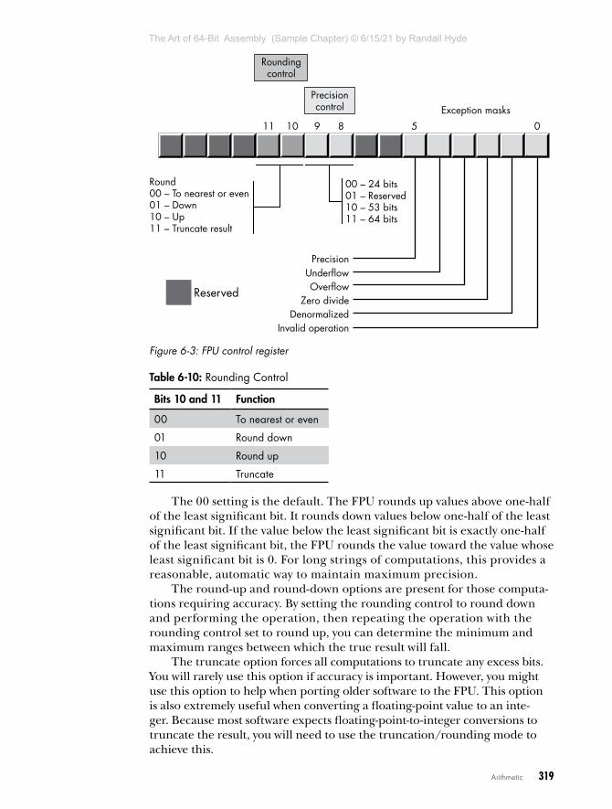
Intel wanted as many applications as possible to work with as few changes as possible on its 8087 FPUs, so it added a special register, the FPU control register, that lets the user choose one of several possible operating modes for the FPU. The 80x87 control register contains 16 bits organized as shown in Figure 6-3.
Bits 10 and 11 of the FPU control register provide rounding control according to the values in Table 6-10.
The Art of 64-Bit Assembly (Sample Chapter) © 6/15/21 by Randall Hyde
T H E A R T O F 6 4 - B I T A S S E M B LY
R A N D A L L H Y D E
6/15/21
Arithmetic 319
Round00 – To nearest or even01 – Down10 – Up11 – Truncate result
Reserved
UnderflowPrecision
OverflowZero divide
DenormalizedInvalid operation
00 – 24 bits01 – Reserved10 – 53 bits11 – 64 bits
Precisioncontrol
Roundingcontrol
Exception masks
0891011 5
Figure 6-3: FPU control register
Table 6-10: Rounding Control
Bits 10 and 11 Function
00 To nearest or even
01 Round down
10 Round up
11 Truncate
The 00 setting is the default. The FPU rounds up values above one-half of the least significant bit. It rounds down values below one-half of the least significant bit. If the value below the least significant bit is exactly one-half of the least significant bit, the FPU rounds the value toward the value whose least significant bit is 0. For long strings of computations, this provides a reasonable, automatic way to maintain maximum precision.
The round-up and round-down options are present for those computa-tions requiring accuracy. By setting the rounding control to round down and performing the operation, then repeating the operation with the rounding control set to round up, you can determine the minimum and maximum ranges between which the true result will fall.
The truncate option forces all computations to truncate any excess bits. You will rarely use this option if accuracy is important. However, you might use this option to help when porting older software to the FPU. This option is also extremely useful when converting a floating-point value to an inte-ger. Because most software expects floating-point-to-integer conversions to truncate the result, you will need to use the truncation/rounding mode to achieve this.
The Art of 64-Bit Assembly (Sample Chapter) © 6/15/21 by Randall Hyde
T H E A R T O F 6 4 - B I T A S S E M B LY
R A N D A L L H Y D E
6/15/21

320 Chapter 6
Bits 8 and 9 of the control register specify the precision during compu-tation. This capability is provided to allow compatibility with older software as required by the IEEE 754 standard. The precision-control bits use the values in Table 6-11.
Table 6-11: Mantissa Precision-Control Bits
Bits 8 and 9 Precision Control
00 24 bits
01 Reserved
10 53 bits
11 64 bits
Some CPUs may operate faster with floating-point values whose preci-sion is 53 bits (that is, 64-bit floating-point format) rather than 64 bits (that is, 80-bit floating-point format). See the documentation for your specific processor for details. Generally, the CPU defaults these bits to 11 to select the 64-bit mantissa precision.
Bits 0 to 5 are the exception masks. These are similar to the interrupt enable bit in the x86-64’s flags register. If these bits contain a 1, the corre-sponding condition is ignored by the FPU. However, if any bit contains 0s, and the corresponding condition occurs, then the FPU immediately gener-ates an interrupt so the program can handle the degenerate condition.
Bit 0 corresponds to an invalid operation error, which generally occurs as the result of a programming error. Situations that raise the invalid operation exception include pushing more than eight items onto the stack or attempting to pop an item off an empty stack, taking the square root of a negative number, or loading a non-empty register.
Bit 1 masks the denormalized interrupt that occurs whenever you try to manipulate denormalized values. Denormalized exceptions occur when you load arbitrary extended-precision values into the FPU or work with very small numbers just beyond the range of the FPU’s capabilities. Normally, you would probably not enable this exception. If you enable this exception and the FPU generates this interrupt, the Windows runtime system raises an exception.
Bit 2 masks the zero-divide exception. If this bit contains 0, the FPU will generate an interrupt if you attempt to divide a nonzero value by 0. If you do not enable the zero-divide exception, the FPU will produce NaN when-ever you perform a zero division. It’s probably a good idea to enable this exception by programming a 0 into this bit. Note that if your program gen-erates this interrupt, the Windows runtime system will raise an exception.
Bit 3 masks the overflow exception. The FPU will raise the overflow exception if a calculation overflows or if you attempt to store a value that is too large to fit into the destination operand (for example, storing a large
The Art of 64-Bit Assembly (Sample Chapter) © 6/15/21 by Randall Hyde
T H E A R T O F 6 4 - B I T A S S E M B LY
R A N D A L L H Y D E
6/15/21

Arithmetic 321
extended-precision value into a single-precision variable). If you enable this exception and the FPU generates this interrupt, the Windows runtime sys-tem raises an exception.
Bit 4, if set, masks the underflow exception. Underflow occurs when the result is too small to fit in the destination operand. Like overflow, this exception can occur whenever you store a small extended-precision value into a smaller variable (single or double precision) or when the result of a computation is too small for extended precision. If you enable this excep-tion and the FPU generates this interrupt, the Windows runtime system raises an exception.
Bit 5 controls whether the precision exception can occur. A precision exception occurs whenever the FPU produces an imprecise result, generally the result of an internal rounding operation. Although many operations will produce an exact result, many more will not. For example, dividing 1 by 10 will produce an inexact result. Therefore, this bit is usually 1 because inexact results are common. If you enable this exception and the FPU gen-erates this interrupt, the Windows runtime system raises an exception.
Bits 6 and 7, and 12 to 15, in the control register are currently unde-fined and reserved for future use (bits 7 and 12 were valid on older FPUs but are no longer used).
The FPU provides two instructions, fldcw (load control word) and fstcw (store control word), that let you load and store the contents of the control reg-ister, respectively. The single operand to these instructions must be a 16-bit memory location. The fldcw instruction loads the control register from the specified memory location. fstcw stores the control register into the specified memory location. The syntax for these instructions is shown here:
fldcw mem16fstcw mem16
Here’s some example code that sets the rounding control to truncate result and sets the rounding precision to 24 bits:
.datafcw16 word ? . . . fstcw fcw16 mov ax, fcw16 and ax, 0f0ffh ; Clears bits 8-11. or ax, 0c00h ; Rounding control=%11, Precision = %00. mov fcw16, ax fldcw fcw16
6.5.3.3 The FPU Status Register
The 16-bit FPU status register provides the status of the FPU at the instant you read it; its layout appears in Figure 6-4. The fstsw instruction stores the 16-bit floating-point status register into a word variable.
The Art of 64-Bit Assembly (Sample Chapter) © 6/15/21 by Randall Hyde
T H E A R T O F 6 4 - B I T A S S E M B LY
R A N D A L L H Y D E
6/15/21

322 Chapter 6
Exception flags
Top of stackpointer
0123456789101112131415
Busy C3 C2 C1 C0
Condition codes
PrecisionUnderflow
Stack faultException flag
OverflowZero divide
DenormalizedInvalid operation
Figure 6-4: The FPU status register
Bits 0 through 5 are the exception flags. These bits appear in the same order as the exception masks in the control register. If the corresponding condition exists, the bit is set. These bits are independent of the exception masks in the control register. The FPU sets and clears these bits regardless of the corresponding mask setting.
Bit 6 indicates a stack fault. A stack fault occurs whenever a stack over-flow or underflow occurs. When this bit is set, the C1 condition code bit determines whether there was a stack overflow (C1 = 1) or stack underflow (C1 = 0) condition.
Bit 7 of the status register is set if any error condition bit is set. It is the logical or of bits 0 through 5. A program can test this bit to quickly deter-mine if an error condition exists.
Bits 8, 9, 10, and 14 are the coprocessor condition code bits. Various instructions set the condition code bits, as shown in Tables 6-12 and 6-13, respectively.
Table 6-12: FPU Condition Code Bits (X = “Don’t care”)
Instruction Condition code bits Condition
C3 C2 C1 C0
fcomfcompfcomppficomficomp
0011
0001
XXXX
0101
ST > sourceST < sourceST = sourceST or source not comparable
ftst 0011
0001
XXXX
0101
ST is positiveST is negativeST is 0 (+ or –)ST is not comparable
The Art of 64-Bit Assembly (Sample Chapter) © 6/15/21 by Randall Hyde
T H E A R T O F 6 4 - B I T A S S E M B LY
R A N D A L L H Y D E
6/15/21

Arithmetic 323
Instruction Condition code bits Condition
C3 C2 C1 C0
fxam 0000111100001
0011001100110
010101010101X
0000000011111
UnsupportedUnsupported+ Normalized– Normalized+ 0– 0+ Denormalized– Denormalized+ NaN– NaN+ Infinity– InfinityEmpty register
fucomfucompfucompp
0011
0001
XXXX
0101
ST > sourceST < sourceST = sourceUnordered / not comparable
Table 6-13: FPU Condition Code Bits (X = “Don’t care”)
Instruction Condition code bits
C0 C3 C2 C1
fcom, fcomp, fcompp, ftst, fucom, fucomp, fucompp, ficom, ficomp
Result of com-parison, see Table 6-12.
Result of com-parison, see Table 6-12.
Operands are not comparable.
Set to 0.
Fxam See Table 6-12. See Table 6-12. See Table 6-12. Sign of result, or stack overflow/underflow if stack exception bit is set.
fprem, fprem1 Bit 2 of quotient Bit 0 of quotient 0—reduction done1—reduction incomplete
Bit 0 of quotient, or stack overflow/underflow if stack exception bit is set.
fist, fbstp, frndint, fst, fstp, fadd, fmul, fdiv, fdivr, fsub, fsubr, fscale, fsqrt, fpatan, f2xm1, fyl2x, fyl2xp1
Undefined Undefined Undefined Rounding direction if exception; other-wise, set to 0.
fptan, fsin, fcos, fsincos
Undefined Undefined Set to 1 if within range; otherwise, 0.
Round-up occurred or stack overflow/underflow if stack exception bit is set. Undefined if C2 is set.
continued
The Art of 64-Bit Assembly (Sample Chapter) © 6/15/21 by Randall Hyde
T H E A R T O F 6 4 - B I T A S S E M B LY
R A N D A L L H Y D E
6/15/21

324 Chapter 6
Instruction Condition code bits
C0 C3 C2 C1
fchs, fabs, fxch, fincstp, fdec-stp, const loads, fxtract, fld, fild, fbld, fstp (80 bit)
Undefined Undefined Undefined Set to 0 or stack overflow/underflow if stack exception bit is set.
fldenv, frstor Restored from memory operand
Restored from memory operand
Restored from memory operand
Restored from memory operand
fldcw, fstenv, fstcw, fstsw, fclex
Undefined Undefined Undefined Undefined
finit, fsave Cleared to 0 Cleared to 0 Cleared to 0 Cleared to 0
Bits 11 to 13 of the FPU status register provide the register number of the top of stack. During computations, the FPU adds (modulo-8) the logical register numbers supplied by the programmer to these 3 bits to determine the physical register number at runtime.
Bit 15 of the status register is the busy bit. It is set whenever the FPU is busy. This bit is a historical artifact from the days when the FPU was a sepa-rate chip; most programs will have little reason to access this bit.
6.5.4 FPU Data TypesThe FPU supports seven data types: three integer types, a packed deci-mal type, and three floating-point types. The integer type supports 16-, 32-, and 64-bit integers, although it is often faster to do the integer arithmetic by using the integer unit of the CPU. The packed decimal type provides an 18-digit signed decimal (BCD) integer. The primary purpose of the BCD format is to convert between strings and floating-point values. The remain-ing three data types are the 32-, 64-, and 80-bit floating-point data types. The 80x87 data types appear in Figures 6-5, 6-6, and 6-7. Just note, for future reference, that the largest BCD value the x87 supports is an 18-digit BCD value (bits 72 to 78 are unused in this format).
The FPU generally stores values in a normalized format. When a float-ing-point number is normalized, the HO bit of the mantissa is always 1. In the 32- and 64-bit floating-point formats, the FPU does not actually store this bit; the FPU always assumes that it is 1. Therefore, 32- and 64-bit float-ing-point numbers are always normalized. In the extended-precision 80-bit floating-point format, the FPU does not assume that the HO bit of the man-tissa is 1; the HO bit of the mantissa appears as part of the string of bits.
Normalized values provide the greatest precision for a given number of bits. However, many non-normalized values cannot be represented with the 80-bit format. These values are very close to 0 and represent the set of val-ues whose mantissa HO bit is not 0. The FPUs support a special 80-bit form known as denormalized values. Denormalized values allow the FPU to encode
The Art of 64-Bit Assembly (Sample Chapter) © 6/15/21 by Randall Hyde
T H E A R T O F 6 4 - B I T A S S E M B LY
R A N D A L L H Y D E
6/15/21

Arithmetic 325
very small values it cannot encode using normalized values, but denormal-ized values offer fewer bits of precision than normalized values. Therefore, using denormalized values in a computation may introduce slight inaccu-racy. Of course, this is always better than underflowing the denormalized value to 0 (which could make the computation even less accurate), but you must keep in mind that if you work with very small values, you may lose some accuracy in your computations. The FPU status register contains a bit you can use to detect when the FPU uses a denormalized value in a computation.
31
32-bit single-precision floating-point format
64-bit single-precision floating-point format
80-bit single-precision floating-point format
... ...
... ...
63 52
79 64
23 16 15
078
078
078
Figure 6-5: FPU floating-point formats
16-bit two’s complement integer
32-bit two’s complement integer
64-bit two’s complement integer
07815
078
... ...
151631
07863
Figure 6-6: FPU integer formats
79
Sign Unused d17 d16
80-bit packed-decimal integer (BCD)
d15 d2 d1 d0
72 71 68 63 59...
8 4 0
Figure 6-7: FPU packed decimal format
6.5.5 The FPU Instruction SetThe FPU adds many instructions to the x86-64 instruction set. We can classify these instructions as data movement instructions, conversions, arithmetic instructions, comparisons, constant instructions, transcenden-tal instructions, and miscellaneous instructions. The following sections describe each of the instructions in these categories.
The Art of 64-Bit Assembly (Sample Chapter) © 6/15/21 by Randall Hyde
T H E A R T O F 6 4 - B I T A S S E M B LY
R A N D A L L H Y D E
6/15/21

326 Chapter 6
6.5.6 FPU Data Movement InstructionsThe data movement instructions transfer data between the internal FPU regis-ters and memory. The instructions in this category are fld, fst, fstp, and fxch. The fld instruction always pushes its operand onto the floating-point stack. The fstp instruction always pops the top of stack (TOS) after storing it. The remaining instructions do not affect the number of items on the stack.
6.5.6.1 The fld Instruction
The fld instruction loads a 32-, 64-, or 80-bit floating-point value onto the stack. This instruction converts 32- and 64-bit operands to an 80-bit extended-precision value before pushing the value onto the floating-point stack.
The fld instruction first decrements the TOS pointer (bits 11 to 13 of the status register) and then stores the 80-bit value in the physical register speci-fied by the new TOS pointer. If the source operand of the fld instruction is a floating-point data register, ST(i), then the actual register that the FPU uses for the load operation is the register number before decrementing the TOS pointer. Therefore, fld st(0) duplicates the value on the top of stack.
The fld instruction sets the stack fault bit if stack overflow occurs. It sets the denormalized exception bit if you load an 80-bit denormalized value. It sets the invalid operation bit if you attempt to load an empty floating-point register onto the TOS (or perform another invalid operation).
Here are some examples:
fld st(1)fld real4_variablefld real8_variablefld real10_variablefld real8 ptr [rbx]
There is no way to directly load a 32-bit integer register onto the floating-point stack, even if that register contains a real4 value. To do so, you must first store the integer register into a memory location, and then push that memory location onto the FPU stack by using the fld instruction. For example:
mov tempReal4, eax ; Save real4 value in EAX to memory.fld tempReal4 ; Push that value onto the FPU stack.
6.5.6.2 The fst and fstp Instructions
The fst and fstp instructions copy the value on the top of the floating-point stack to another floating-point register or to a 32-, 64-, or (fstp only) 80-bit memory variable. When copying data to a 32- or 64-bit memory variable, the FPU rounds the 80-bit extended-precision value on the TOS to the smaller format as specified by the rounding control bits in the FPU control register.
The fstp instruction pops the value off the top of stack when moving it to the destination location, by incrementing the TOS pointer in the status
The Art of 64-Bit Assembly (Sample Chapter) © 6/15/21 by Randall Hyde
T H E A R T O F 6 4 - B I T A S S E M B LY
R A N D A L L H Y D E
6/15/21

Arithmetic 327
register after accessing the data in ST(0). If the destination operand is a floating-point register, the FPU stores the value at the specified register number before popping the data off the top of stack.
Executing an fstp st(0) instruction effectively pops the data off the top of stack with no data transfer. Here are some examples:
fst real4_variablefst real8_variablefst realArray[rbx * 8]fst st(2)fstp st(1)
The last example effectively pops ST(1) while leaving ST(0) on the top of stack.
The fst and fstp instructions will set the stack exception bit if a stack underflow occurs (attempting to store a value from an empty register stack). They will set the precision bit if a loss of precision occurs during the store operation (for example, when storing an 80-bit extended-precision value into a 32- or 64-bit memory variable and some bits are lost during conver-sion). They will set the underflow exception bit when storing an 80-bit value into a 32- or 64-bit memory variable, but the value is too small to fit into the destination operand. Likewise, these instructions will set the overflow exception bit if the value on the top of stack is too big to fit into a 32- or 64-bit memory variable. They set the invalid operation flag if an invalid operation (such as storing into an empty register) occurs. Finally, these instructions set the C1 condition bit if rounding occurs during the store operation (this occurs only when storing into a 32- or 64-bit memory vari-able and you have to round the mantissa to fit into the destination) or if a stack fault occurs.
NO T E Because of an idiosyncrasy in the FPU instruction set related to the encoding of the instructions, you cannot use the fst instruction to store data into a real10 memory variable. You may, however, store 80-bit data by using the fstp instruction.
6.5.6.3 The fxch Instruction
The fxch instruction exchanges the value on the top of stack with one of the other FPU registers. This instruction takes two forms: one with a single FPU register as an operand and the second without any operands. The first form exchanges the top of stack with the specified register. The second form of fxch swaps the top of stack with ST(1).
Many FPU instructions (for example, fsqrt) operate only on the top of the register stack. If you want to perform such an operation on a value that is not on top, you can use the fxch instruction to swap that register with TOS, perform the desired operation, and then use fxch to swap the TOS with the original register. The following example takes the square root of ST(2):
fxch st(2)fsqrtfxch st(2)
The Art of 64-Bit Assembly (Sample Chapter) © 6/15/21 by Randall Hyde
T H E A R T O F 6 4 - B I T A S S E M B LY
R A N D A L L H Y D E
6/15/21

328 Chapter 6
The fxch instruction sets the stack exception bit if the stack is empty; it sets the invalid operation bit if you specify an empty register as the oper-and; and, it always clears the C1 condition code bit.
6.5.7 ConversionsThe FPU performs all arithmetic operations on 80-bit real quantities. In a sense, the fld and fst/fstp instructions are conversion instructions because they automatically convert between the internal 80-bit real format and the 32- and 64-bit memory formats. Nonetheless, we’ll classify them as data movement operations, rather than conversions, because they are moving real values to and from memory. The FPU provides six other instructions that convert to or from integer or BCD format when moving data. These instructions are fild, fist, fistp, fisttp, fbld, and fbstp.
6.5.7.1 The fild Instruction
The fild (integer load) instruction converts a 16-, 32-, or 64-bit two’s comple-ment integer to the 80-bit extended-precision format and pushes the result onto the stack. This instruction always expects a single operand: the address of a word, double-word, or quad-word integer variable. You cannot specify one of the x86-64’s 16-, 32-, or 64-bit general-purpose registers. If you want to push the value of an x86-64 general-purpose register onto the FPU stack, you must first store it into a memory variable and then use fild to push that memory variable.
The fild instruction sets the stack exception bit and C1 (accordingly) if stack overflow occurs while pushing the converted value. Look at these examples:
fild word_variable fild dword_val[rcx * 4]fild qword_variablefild sqword ptr [rbx]
6.5.7.2 The fist, fistp, and fisttp Instructions
The fist, fistp, and fisttp instructions convert the 80-bit extended-preci-sion variable on the top of stack to a 16-, 32-, or (fistp/fistpp only) 64-bit integer and store the result away into the memory variable specified by the single operand. The fist and fistp instructions convert the value on TOS to an integer according to the rounding setting in the FPU control register (bits 10 and 11). The fisttp instruction always does the conversion using the truncation mode. As with the fild instruction, the fist, fistp, and fisttp instructions will not let you specify one of the x86-64’s general-purpose 16-, 32-, or 64-bit registers as the destination operand.
The fist instruction converts the value on the top of stack to an integer and then stores the result; it does not otherwise affect the floating-point register stack. The fistp and fisttp instructions pop the value off the floating-point register stack after storing the converted value.
The Art of 64-Bit Assembly (Sample Chapter) © 6/15/21 by Randall Hyde
T H E A R T O F 6 4 - B I T A S S E M B LY
R A N D A L L H Y D E
6/15/21

Arithmetic 329
These instructions set the stack exception bit if the floating-point regis-ter stack is empty (this will also clear C1). They set the precision (imprecise operation) and C1 bits if rounding occurs (that is, if the value in ST(0) has any fractional component). These instructions set the underflow exception bit if the result is too small (less than 1 but greater than 0, or less than 0 but greater than –1). Here are some examples:
fist word_var[rbx * 2]fist dword_varfisttp dword_varfistp qword_var
The fist and fistp instructions use the rounding control settings to determine how they will convert the floating-point data to an integer during the store operation. Be default, the rounding control is usually set to round mode; yet most programmers expect fist/fistp to truncate the decimal portion during conversion. If you want fist/fistp to truncate floating-point values when converting them to an integer, you will need to set the rounding control bits appropriately in the floating-point control register (or use the fisttp instruction to truncate the result regardless of the rounding control bits). Here’s an example:
.datafcw16 word ?fcw16_2 word ?IntResult sdword ? . . . fstcw fcw16 mov ax, fcw16 or ax, 0c00h ; Rounding =%11 (truncate). mov fcw16_2, ax ; Store and reload the ctrl word. fldcw fcw16_2
fistp IntResult ; Truncate ST(0) and store as int32.
fldcw fcw16 ; Restore original rounding control.
6.5.7.3 The fbld and fbstp Instructions
The fbld and fbstp instructions load and store 80-bit BCD values. The fbld instruction converts a BCD value to its 80-bit extended-precision equiva-lent and pushes the result onto the stack. The fbstp instruction pops the extended-precision real value on TOS, converts it to an 80-bit BCD value (rounding according to the bits in the floating-point control register), and stores the converted result at the address specified by the destination mem-ory operand. There is no fbst instruction.
The fbld instruction sets the stack exception bit and C1 if stack overflow occurs. The results are undefined if you attempt to load an invalid BCD
The Art of 64-Bit Assembly (Sample Chapter) © 6/15/21 by Randall Hyde
T H E A R T O F 6 4 - B I T A S S E M B LY
R A N D A L L H Y D E
6/15/21

330 Chapter 6
value. The fbstp instruction sets the stack exception bit and clears C1 if stack underflow occurs (the stack is empty). It sets the underflow flag under the same conditions as fist and fistp. Look at these examples:
; Assuming fewer than eight items on the stack, the following; code sequence is equivalent to an fbst instruction:
fld st(0) fbstp tbyte_var
; The following example easily converts an 80-bit BCD value to; a 64-bit integer:
fbld tbyte_var fistp qword_var
These two instructions are especially useful for converting between string and floating-point formats. Along with the fild and fist instructions, you can use fbld and fbstp to convert between integer and string formats (see “Unsigned Decimal to String Conversion” in Chapter 9).
6.5.8 Arithmetic InstructionsArithmetic instructions make up a small but important subset of the FPU’s instruction set. These instructions fall into two general categories: those that operate on real values and those that operate on a real and an integer value.
6.5.8.1 The fadd, faddp, and fiadd Instructions
The fadd, faddp, and fiadd instructions take the following forms:
faddfaddpfadd st(i), st(0)fadd st(0), st(i)faddp st(i), st(0)fadd mem32fadd mem64fiadd mem16fiadd mem32
The fadd instruction, with no operands, is a synonym for faddp. The faddp instruction (also with no operands) pops the two values on the top of stack, adds them, and pushes their sum back onto the stack.
The next two forms of the fadd instruction, those with two FPU register operands, behave like the x86-64’s add instruction. They add the value in the source register operand to the value in the destination register oper-and. One of the register operands must be ST(0).
The faddp instruction with two operands adds ST(0) (which must always be the source operand) to the destination operand and then pops ST(0). The destination operand must be one of the other FPU registers.
The Art of 64-Bit Assembly (Sample Chapter) © 6/15/21 by Randall Hyde
T H E A R T O F 6 4 - B I T A S S E M B LY
R A N D A L L H Y D E
6/15/21

Arithmetic 331
The last two forms, fadd with a memory operand, adds a 32- or 64-bit floating-point variable to the value in ST(0). This instruction will convert the 32- or 64-bit operands to an 80-bit extended-precision value before performing the addition. Note that this instruction does not allow an 80-bit memory operand. There are also instructions for adding 16- and 32-bit inte-gers in memory to ST(0): fiadd mem16 and fiadd mem32.
These instructions can raise the stack, precision, underflow, overflow, denormalized, and illegal operation exceptions, as appropriate. If a stack fault exception occurs, C1 denotes stack overflow or underflow, or the rounding direction (see Table 6-13).
Listing 6-1 demonstrates the various forms of the fadd instruction.
; Listing 6-1;; Demonstration of various forms of fadd
option casemap:none
nl = 10
.constttlStr byte "Listing 6-1", 0fmtSt0St1 byte "st(0):%f, st(1):%f", nl, 0fmtAdd1 byte "fadd: st0:%f", nl, 0fmtAdd2 byte "faddp: st0:%f", nl, 0fmtAdd3 byte "fadd st(1), st(0): st0:%f, st1:%f", nl, 0fmtAdd4 byte "fadd st(0), st(1): st0:%f, st1:%f", nl, 0fmtAdd5 byte "faddp st(1), st(0): st0:%f", nl, 0fmtAdd6 byte "fadd mem: st0:%f", nl, 0
zero real8 0.0one real8 1.0two real8 2.0minusTwo real8 -2.0
.datast0 real8 0.0st1 real8 0.0
.code externdef printf:proc
; Return program title to C++ program:
public getTitlegetTitle proc lea rax, ttlStr retgetTitle endp
The Art of 64-Bit Assembly (Sample Chapter) © 6/15/21 by Randall Hyde
T H E A R T O F 6 4 - B I T A S S E M B LY
R A N D A L L H Y D E
6/15/21

332 Chapter 6
; printFP- Prints values of st0 and (possibly) st1.; Caller must pass in ptr to fmtStr in RCX.
printFP proc sub rsp, 40
; For varargs (for example, printf call), double; values must appear in RDX and R8 rather; than XMM1, XMM2.; Note: if only one double arg in format; string, printf call will ignore 2nd; value in R8.
mov rdx, qword ptr st0 mov r8, qword ptr st1 call printf add rsp, 40 retprintFP endp
; Here is the "asmMain" function.
public asmMainasmMain proc push rbp mov rbp, rsp sub rsp, 48 ;Shadow storage ; Demonstrate various fadd instructions:
mov rax, qword ptr one mov qword ptr st1, rax mov rax, qword ptr minusTwo mov qword ptr st0, rax lea rcx, fmtSt0St1 call printFP
; fadd (same as faddp) fld one fld minusTwo fadd ;Pops st(0)! fstp st0
lea rcx, fmtAdd1 call printFP ; faddp: fld one fld minusTwo
The Art of 64-Bit Assembly (Sample Chapter) © 6/15/21 by Randall Hyde
T H E A R T O F 6 4 - B I T A S S E M B LY
R A N D A L L H Y D E
6/15/21
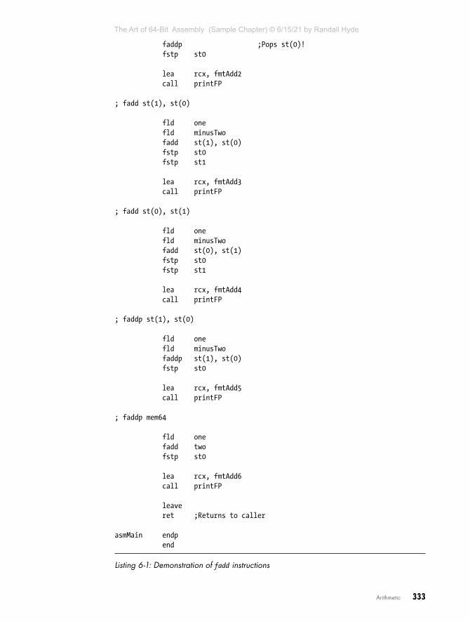
Arithmetic 333
faddp ;Pops st(0)! fstp st0
lea rcx, fmtAdd2 call printFP
; fadd st(1), st(0) fld one fld minusTwo fadd st(1), st(0) fstp st0 fstp st1
lea rcx, fmtAdd3 call printFP
; fadd st(0), st(1)
fld one fld minusTwo fadd st(0), st(1) fstp st0 fstp st1
lea rcx, fmtAdd4 call printFP
; faddp st(1), st(0)
fld one fld minusTwo faddp st(1), st(0) fstp st0 lea rcx, fmtAdd5 call printFP
; faddp mem64
fld one fadd two fstp st0
lea rcx, fmtAdd6 call printFP
leave ret ;Returns to caller
asmMain endp end
Listing 6-1: Demonstration of fadd instructions
The Art of 64-Bit Assembly (Sample Chapter) © 6/15/21 by Randall Hyde
T H E A R T O F 6 4 - B I T A S S E M B LY
R A N D A L L H Y D E
6/15/21

334 Chapter 6
Here’s the build command and output for the program in Listing 6-1:
C:\>build listing6-1
C:\>echo off Assembling: listing6-1.asmc.cpp
C:\>listing6-1Calling Listing 6-1:st(0):-2.000000, st(1):1.000000fadd: st0:-1.000000faddp: st0:-1.000000fadd st(1), st(0): st0:-2.000000, st1:-1.000000fadd st(0), st(1): st0:-1.000000, st1:1.000000faddp st(1), st(0): st0:-1.000000fadd mem: st0:3.000000Listing 6-1 terminated
6.5.8.2 The fsub, fsubp, fsubr, fsubrp, fisub, and fisubr Instructions
These six instructions take the following forms:
fsubfsubpfsubrfsubrp
fsub st(i), st(0)fsub st(0), st(i)fsubp st(i), st(0)fsub mem32fsub mem64
fsubr st(i) , st(0)fsubr st(0), st(i)fsubrp st(i) , st(0)fsubr mem32fsubr mem64
fisub mem16fisub mem32fisubr mem16fisubr mem32
With no operands, fsub is the same as fsubp (without operands). With no operands, the fsubp instruction pops ST(0) and ST(1) from the register stack, computes ST(1) – ST(0), and then pushes the difference back onto the stack. The fsubr and fsubrp instructions (reverse subtraction) operate in an identical fashion except they compute ST(0) – ST(1).
With two register operands (destination, source), the fsub instruction computes destination = destination – source. One of the two registers must be
The Art of 64-Bit Assembly (Sample Chapter) © 6/15/21 by Randall Hyde
T H E A R T O F 6 4 - B I T A S S E M B LY
R A N D A L L H Y D E
6/15/21

Arithmetic 335
ST(0). With two registers as operands, the fsubp also computes destination = destination – source, and then it pops ST(0) off the stack after computing the difference. For the fsubp instruction, the source operand must be ST(0).
With two register operands, the fsubr and fsubrp instructions work in a similar fashion to fsub and fsubp, except they compute destination = source – destination.
The fsub mem32, fsub mem64, fsubr mem32, and fsubr mem64 instructions accept a 32- or 64-bit memory operand. They convert the memory operand to an 80-bit extended-precision value and subtract this from ST(0) (fsub) or subtract ST(0) from this value (fsubr) and store the result back into ST(0). There are also instructions for subtracting 16- and 32-bit integers in memory from ST(0): fisub mem16 and fisub mem32 (also fisubr mem16 and fisubr mem32).
These instructions can raise the stack, precision, underflow, overflow, denormalized, and illegal operation exceptions, as appropriate. If a stack fault exception occurs, C1 denotes stack overflow or underflow, or indicates the rounding direction (see Table 6-13).
Listing 6-2 demonstrates the fsub/fsubr instructions.
; Listing 6-2;; Demonstration of various forms of fsub/fsubrl
option casemap:none
nl = 10
.constttlStr byte "Listing 6-2", 0fmtSt0St1 byte "st(0):%f, st(1):%f", nl, 0fmtSub1 byte "fsub: st0:%f", nl, 0fmtSub2 byte "fsubp: st0:%f", nl, 0fmtSub3 byte "fsub st(1), st(0): st0:%f, st1:%f", nl, 0fmtSub4 byte "fsub st(0), st(1): st0:%f, st1:%f", nl, 0fmtSub5 byte "fsubp st(1), st(0): st0:%f", nl, 0fmtSub6 byte "fsub mem: st0:%f", nl, 0fmtSub7 byte "fsubr st(1), st(0): st0:%f, st1:%f", nl, 0fmtSub8 byte "fsubr st(0), st(1): st0:%f, st1:%f", nl, 0fmtSub9 byte "fsubrp st(1), st(0): st0:%f", nl, 0fmtSub10 byte "fsubr mem: st0:%f", nl, 0
zero real8 0.0three real8 3.0minusTwo real8 -2.0
.datast0 real8 0.0st1 real8 0.0
.code externdef printf:proc
The Art of 64-Bit Assembly (Sample Chapter) © 6/15/21 by Randall Hyde
T H E A R T O F 6 4 - B I T A S S E M B LY
R A N D A L L H Y D E
6/15/21

336 Chapter 6
; Return program title to C++ program:
public getTitlegetTitle proc lea rax, ttlStr retgetTitle endp
; printFP- Prints values of st0 and (possibly) st1.; Caller must pass in ptr to fmtStr in RCX.
printFP proc sub rsp, 40
; For varargs (for example, printf call), double; values must appear in RDX and R8 rather; than XMM1, XMM2.; Note: if only one double arg in format; string, printf call will ignore 2nd; value in R8.
mov rdx, qword ptr st0 mov r8, qword ptr st1 call printf add rsp, 40 retprintFP endp
; Here is the "asmMain" function.
public asmMainasmMain proc push rbp mov rbp, rsp sub rsp, 48 ;Shadow storage
; Demonstrate various fsub instructions:
mov rax, qword ptr three mov qword ptr st1, rax mov rax, qword ptr minusTwo mov qword ptr st0, rax lea rcx, fmtSt0St1 call printFP
; fsub (same as fsubp) fld three fld minusTwo fsub ;Pops st(0)! fstp st0
The Art of 64-Bit Assembly (Sample Chapter) © 6/15/21 by Randall Hyde
T H E A R T O F 6 4 - B I T A S S E M B LY
R A N D A L L H Y D E
6/15/21

Arithmetic 337
lea rcx, fmtSub1 call printFP
; fsubp:
fld three fld minusTwo fsubp ;Pops st(0)! fstp st0
lea rcx, fmtSub2 call printFP
; fsub st(1), st(0)
fld three fld minusTwo fsub st(1), st(0) fstp st0 fstp st1
lea rcx, fmtSub3 call printFP
; fsub st(0), st(1) fld three fld minusTwo fsub st(0), st(1) fstp st0 fstp st1
lea rcx, fmtSub4 call printFP
; fsubp st(1), st(0)
fld three fld minusTwo fsubp st(1), st(0) fstp st0
lea rcx, fmtSub5 call printFP
; fsub mem64
fld three fsub minusTwo fstp st0
lea rcx, fmtSub6 call printFP
; fsubr st(1), st(0)
The Art of 64-Bit Assembly (Sample Chapter) © 6/15/21 by Randall Hyde
T H E A R T O F 6 4 - B I T A S S E M B LY
R A N D A L L H Y D E
6/15/21

338 Chapter 6
fld three fld minusTwo fsubr st(1), st(0) fstp st0 fstp st1
lea rcx, fmtSub7 call printFP
; fsubr st(0), st(1)
fld three fld minusTwo fsubr st(0), st(1) fstp st0 fstp st1
lea rcx, fmtSub8 call printFP
; fsubrp st(1), st(0)
fld three fld minusTwo fsubrp st(1), st(0) fstp st0
lea rcx, fmtSub9 call printFP
; fsubr mem64
fld three fsubr minusTwo fstp st0
lea rcx, fmtSub10 call printFP
leave ret ;Returns to caller
asmMain endp end
Listing 6-2: Demonstration of the fsub instructions
Here’s the build command and output for Listing 6-2:
C:\>build listing6-2
C:\>echo off Assembling: listing6-2.asmc.cpp
The Art of 64-Bit Assembly (Sample Chapter) © 6/15/21 by Randall Hyde
T H E A R T O F 6 4 - B I T A S S E M B LY
R A N D A L L H Y D E
6/15/21

Arithmetic 339
C:\>listing6-2Calling Listing 6-2:st(0):-2.000000, st(1):3.000000fsub: st0:5.000000fsubp: st0:5.000000fsub st(1), st(0): st0:-2.000000, st1:5.000000fsub st(0), st(1): st0:-5.000000, st1:3.000000fsubp st(1), st(0): st0:5.000000fsub mem: st0:5.000000fsubr st(1), st(0): st0:-2.000000, st1:-5.000000fsubr st(0), st(1): st0:5.000000, st1:3.000000fsubrp st(1), st(0): st0:-5.000000fsubr mem: st0:-5.000000Listing 6-2 terminated
6.5.8.3 The fmul, fmulp, and fimul Instructions
The fmul and fmulp instructions multiply two floating-point values. The fimul instruction multiples an integer and a floating-point value. These instruc-tions allow the following forms:
fmulfmulp
fmul st(0), st(i)fmul st(i), st(0)fmul mem32fmul mem64
fmulp st(i), st(0)
fimul mem16fimul mem32
With no operands, fmul is a synonym for fmulp. The fmulp instruction, with no operands, will pop ST(0) and ST(1), multiply these values, and push their product back onto the stack. The fmul instructions with two register operands compute destination = destination × source. One of the registers (source or destination) must be ST(0).
The fmulp st(0), st(i) instruction computes ST(i) = ST(i) × ST(0) and then pops ST(0). This instruction uses the value for i before popping ST(0). The fmul mem32 and fmul mem64 instructions require a 32- or 64-bit memory operand, respectively. They convert the specified memory variable to an 80-bit extended-precision value and then multiply ST(0) by this value. There are also instructions for multiplying 16- and 32-bit integers in mem-ory by ST(0): fimul mem16 and fimul mem32.
These instructions can raise the stack, precision, underflow, overflow, denormalized, and illegal operation exceptions, as appropriate. If rounding occurs during the computation, these instructions set the C1 condition code bit. If a stack fault exception occurs, C1 denotes stack overflow or underflow.
The Art of 64-Bit Assembly (Sample Chapter) © 6/15/21 by Randall Hyde
T H E A R T O F 6 4 - B I T A S S E M B LY
R A N D A L L H Y D E
6/15/21
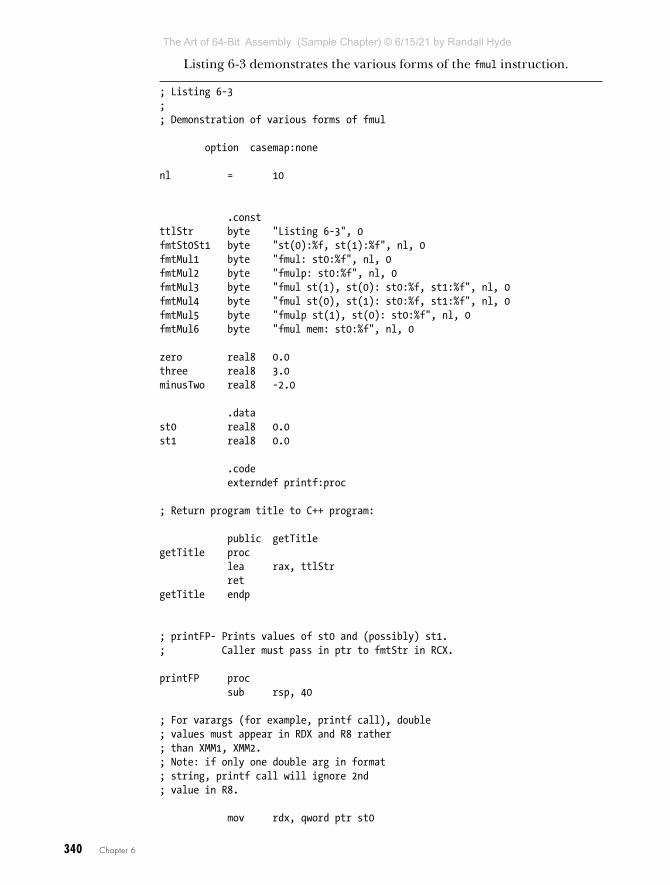
340 Chapter 6
Listing 6-3 demonstrates the various forms of the fmul instruction.
; Listing 6-3;; Demonstration of various forms of fmul
option casemap:none
nl = 10
.constttlStr byte "Listing 6-3", 0fmtSt0St1 byte "st(0):%f, st(1):%f", nl, 0fmtMul1 byte "fmul: st0:%f", nl, 0fmtMul2 byte "fmulp: st0:%f", nl, 0fmtMul3 byte "fmul st(1), st(0): st0:%f, st1:%f", nl, 0fmtMul4 byte "fmul st(0), st(1): st0:%f, st1:%f", nl, 0fmtMul5 byte "fmulp st(1), st(0): st0:%f", nl, 0fmtMul6 byte "fmul mem: st0:%f", nl, 0
zero real8 0.0three real8 3.0minusTwo real8 -2.0
.datast0 real8 0.0st1 real8 0.0
.code externdef printf:proc
; Return program title to C++ program:
public getTitlegetTitle proc lea rax, ttlStr retgetTitle endp
; printFP- Prints values of st0 and (possibly) st1.; Caller must pass in ptr to fmtStr in RCX.
printFP proc sub rsp, 40
; For varargs (for example, printf call), double; values must appear in RDX and R8 rather; than XMM1, XMM2.; Note: if only one double arg in format; string, printf call will ignore 2nd; value in R8.
mov rdx, qword ptr st0
The Art of 64-Bit Assembly (Sample Chapter) © 6/15/21 by Randall Hyde
T H E A R T O F 6 4 - B I T A S S E M B LY
R A N D A L L H Y D E
6/15/21

Arithmetic 341
mov r8, qword ptr st1 call printf add rsp, 40 retprintFP endp
; Here is the "asmMain" function.
public asmMainasmMain proc push rbp mov rbp, rsp sub rsp, 48 ;Shadow storage
; Demonstrate various fmul instructions:
mov rax, qword ptr three mov qword ptr st1, rax mov rax, qword ptr minusTwo mov qword ptr st0, rax lea rcx, fmtSt0St1 call printFP
; fmul (same as fmulp)
fld three fld minusTwo fmul ;Pops st(0)! fstp st0
lea rcx, fmtMul1 call printFP
; fmulp:
fld three fld minusTwo fmulp ;Pops st(0)! fstp st0
lea rcx, fmtMul2 call printFP
; fmul st(1), st(0)
fld three fld minusTwo fmul st(1), st(0) fstp st0 fstp st1
lea rcx, fmtMul3 call printFP
The Art of 64-Bit Assembly (Sample Chapter) © 6/15/21 by Randall Hyde
T H E A R T O F 6 4 - B I T A S S E M B LY
R A N D A L L H Y D E
6/15/21

342 Chapter 6
; fmul st(0), st(1)
fld three fld minusTwo fmul st(0), st(1) fstp st0 fstp st1
lea rcx, fmtMul4 call printFP
; fmulp st(1), st(0)
fld three fld minusTwo fmulp st(1), st(0) fstp st0
lea rcx, fmtMul5 call printFP
; fmulp mem64
fld three fmul minusTwo fstp st0
lea rcx, fmtMul6 call printFP
leave ret ;Returns to caller
asmMain endp end
Listing 6-3: Demonstration of the fmul instruction
Here is the build command and output for Listing 6-3:
C:\>build listing6-3
C:\>echo off Assembling: listing6-3.asmc.cpp
C:\>listing6-3Calling Listing 6-3:st(0):-2.000000, st(1):3.000000fmul: st0:-6.000000fmulp: st0:-6.000000fmul st(1), st(0): st0:-2.000000, st1:-6.000000fmul st(0), st(1): st0:-6.000000, st1:3.000000
The Art of 64-Bit Assembly (Sample Chapter) © 6/15/21 by Randall Hyde
T H E A R T O F 6 4 - B I T A S S E M B LY
R A N D A L L H Y D E
6/15/21

Arithmetic 343
fmulp st(1), st(0): st0:-6.000000fmul mem: st0:-6.000000Listing 6-3 terminated
6.5.8.4 The fdiv, fdivp, fdivr, fdivrp, fidiv, and fidivr Instructions
These four instructions allow the following forms:
fdivfdivpfdivrfdivrp
fdiv st(0), st(i)fdiv st(i), st(0)fdivp st(i), st(0)
fdivr st(0), st(i)fdivr st(i), st(0)fdivrp st(i), st(0)
fdiv mem32fdiv mem64fdivr mem32fdivr mem64
fidiv mem16fidiv mem32fidivr mem16fidivr mem32
With no operands, the fdiv instruction is a synonym for fdivp. The fdivp instruction with no operands computes ST(1) = ST(1) / ST(0). The fdivr and fdivrp instructions work in a similar fashion to fdiv and fdivp except that they compute ST(0) / ST(1) rather than ST(1) / ST(0).
With two register operands, these instructions compute the following quotients:
fdiv st(0), st(i) ; st(0) = st(0)/st(i)fdiv st(i), st(0) ; st(i) = st(i)/st(0)fdivp st(i), st(0) ; st(i) = st(i)/st(0) then pop st0fdivr st(0), st(i) ; st(0) = st(i)/st(0)fdivr st(i), st(0) ; st(i) = st(0)/st(i)fdivrp st(i), st(0) ; st(i) = st(0)/st(i) then pop st0
The fdivp and fdivrp instructions also pop ST(0) after performing the division operation. The value for i in these two instructions is computed before popping ST(0).
These instructions can raise the stack, precision, underflow, overflow, denormalized, zero divide, and illegal operation exceptions, as appropriate.
The Art of 64-Bit Assembly (Sample Chapter) © 6/15/21 by Randall Hyde
T H E A R T O F 6 4 - B I T A S S E M B LY
R A N D A L L H Y D E
6/15/21

344 Chapter 6
If rounding occurs during the computation, these instructions set the C1 condition code bit. If a stack fault exception occurs, C1 denotes stack over-flow or underflow.
Listing 6-4 provides a demonstration of the fdiv/fdivr instructions.
; Listing 6-4;; Demonstration of various forms of fsub/fsubrl
option casemap:none
nl = 10
.constttlStr byte "Listing 6-4", 0fmtSt0St1 byte "st(0):%f, st(1):%f", nl, 0fmtDiv1 byte "fdiv: st0:%f", nl, 0fmtDiv2 byte "fdivp: st0:%f", nl, 0fmtDiv3 byte "fdiv st(1), st(0): st0:%f, st1:%f", nl, 0fmtDiv4 byte "fdiv st(0), st(1): st0:%f, st1:%f", nl, 0fmtDiv5 byte "fdivp st(1), st(0): st0:%f", nl, 0fmtDiv6 byte "fdiv mem: st0:%f", nl, 0fmtDiv7 byte "fdivr st(1), st(0): st0:%f, st1:%f", nl, 0fmtDiv8 byte "fdivr st(0), st(1): st0:%f, st1:%f", nl, 0fmtDiv9 byte "fdivrp st(1), st(0): st0:%f", nl, 0fmtDiv10 byte "fdivr mem: st0:%f", nl, 0
three real8 3.0minusTwo real8 -2.0
.datast0 real8 0.0st1 real8 0.0
.code externdef printf:proc
; Return program title to C++ program:
public getTitlegetTitle proc lea rax, ttlStr retgetTitle endp
; printFP- Prints values of st0 and (possibly) st1.; Caller must pass in ptr to fmtStr in RCX.
printFP proc sub rsp, 40
; For varargs (for example, printf call), double
The Art of 64-Bit Assembly (Sample Chapter) © 6/15/21 by Randall Hyde
T H E A R T O F 6 4 - B I T A S S E M B LY
R A N D A L L H Y D E
6/15/21

Arithmetic 345
; values must appear in RDX and R8 rather; than XMM1, XMM2.; Note: if only one double arg in format; string, printf call will ignore 2nd; value in R8.
mov rdx, qword ptr st0 mov r8, qword ptr st1 call printf add rsp, 40 retprintFP endp
; Here is the "asmMain" function.
public asmMainasmMain proc push rbp mov rbp, rsp sub rsp, 48 ;Shadow storage
; Demonstrate various fdiv instructions:
mov rax, qword ptr three mov qword ptr st1, rax mov rax, qword ptr minusTwo mov qword ptr st0, rax lea rcx, fmtSt0St1 call printFP
; fdiv (same as fdivp)
fld three fld minusTwo fdiv ;Pops st(0)! fstp st0
lea rcx, fmtDiv1 call printFP
; fdivp: fld three fld minusTwo fdivp ;Pops st(0)! fstp st0
lea rcx, fmtDiv2 call printFP
; fdiv st(1), st(0)
fld three
The Art of 64-Bit Assembly (Sample Chapter) © 6/15/21 by Randall Hyde
T H E A R T O F 6 4 - B I T A S S E M B LY
R A N D A L L H Y D E
6/15/21

346 Chapter 6
fld minusTwo fdiv st(1), st(0) fstp st0 fstp st1
lea rcx, fmtDiv3 call printFP
; fdiv st(0), st(1)
fld three fld minusTwo fdiv st(0), st(1) fstp st0 fstp st1
lea rcx, fmtDiv4 call printFP
; fdivp st(1), st(0)
fld three fld minusTwo fdivp st(1), st(0) fstp st0
lea rcx, fmtDiv5 call printFP
; fdiv mem64 fld three fdiv minusTwo fstp st0
lea rcx, fmtDiv6 call printFP
; fdivr st(1), st(0)
fld three fld minusTwo fdivr st(1), st(0) fstp st0 fstp st1
lea rcx, fmtDiv7 call printFP
; fdivr st(0), st(1)
fld three fld minusTwo fdivr st(0), st(1) fstp st0
The Art of 64-Bit Assembly (Sample Chapter) © 6/15/21 by Randall Hyde
T H E A R T O F 6 4 - B I T A S S E M B LY
R A N D A L L H Y D E
6/15/21
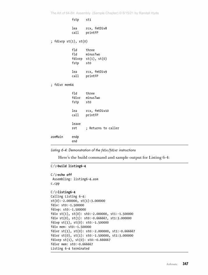
Arithmetic 347
fstp st1
lea rcx, fmtDiv8 call printFP
; fdivrp st(1), st(0)
fld three fld minusTwo fdivrp st(1), st(0) fstp st0 lea rcx, fmtDiv9 call printFP
; fdivr mem64
fld three fdivr minusTwo fstp st0
lea rcx, fmtDiv10 call printFP
leave ret ; Returns to caller
asmMain endp end
Listing 6-4: Demonstration of the fdiv/fdivr instructions
Here’s the build command and sample output for Listing 6-4:
C:\>build listing6-4
C:\>echo off Assembling: listing6-4.asmc.cpp
C:\>listing6-4Calling Listing 6-4:st(0):-2.000000, st(1):3.000000fdiv: st0:-1.500000fdivp: st0:-1.500000fdiv st(1), st(0): st0:-2.000000, st1:-1.500000fdiv st(0), st(1): st0:-0.666667, st1:3.000000fdivp st(1), st(0): st0:-1.500000fdiv mem: st0:-1.500000fdivr st(1), st(0): st0:-2.000000, st1:-0.666667fdivr st(0), st(1): st0:-1.500000, st1:3.000000fdivrp st(1), st(0): st0:-0.666667fdivr mem: st0:-0.666667Listing 6-4 terminated
The Art of 64-Bit Assembly (Sample Chapter) © 6/15/21 by Randall Hyde
T H E A R T O F 6 4 - B I T A S S E M B LY
R A N D A L L H Y D E
6/15/21

348 Chapter 6
6.5.8.5 The fsqrt Instruction
The fsqrt routine does not allow any operands. It computes the square root of the value on TOS and replaces ST(0) with this result. The value on TOS must be 0 or positive; otherwise, fsqrt will generate an invalid operation exception.
This instruction can raise the stack, precision, denormalized, and invalid operation exceptions, as appropriate. If rounding occurs during the computation, fsqrt sets the C1 condition code bit. If a stack fault exception occurs, C1 denotes stack overflow or underflow.
Here’s an example:
; Compute z = sqrt(x**2 + y**2);
fld x ; Load x. fld st(0) ; Duplicate x on TOS. fmulp ; Compute x**2.
fld y ; Load y. fld st(0) ; Duplicate y. fmul ; Compute y**2.
faddp ; Compute x**2 + y**2. fsqrt ; Compute sqrt( x**2 + y**2 ). fstp z ; Store result away into z.
6.5.8.6 The fprem and fprem1 Instructions
The fprem and fprem1 instructions compute a partial remainder (a value that may require additional computation to produce the actual remainder). Intel designed the fprem instruction before the IEEE finalized its floating-point standard. In the final draft of that standard, the definition of fprem was a little different from Intel’s original design. To maintain compatibility with the existing software that used the fprem instruction, Intel designed a new version to handle the IEEE partial remainder operation, fprem1. You should always use fprem1 in new software; therefore, we will discuss only fprem1 here, although you use fprem in an identical fashion.
fprem1 computes the partial remainder of ST(0) / ST(1). If the differ-ence between the exponents of ST(0) and ST(1) is less than 64, fprem1 can compute the exact remainder in one operation. Otherwise, you will have to execute fprem1 two or more times to get the correct remainder value. The C2 condition code bit determines when the computation is complete. Note that fprem1 does not pop the two operands off the stack; it leaves the partial remainder in ST(0) and the original divisor in ST(1) in case you need to compute another partial product to complete the result.
The fprem1 instruction sets the stack exception flag if there aren’t two values on the top of stack. It sets the underflow and denormal exception bits if the result is too small. It sets the invalid operation bit if the values on TOS are inappropriate for this operation. It sets the C2 condition code
The Art of 64-Bit Assembly (Sample Chapter) © 6/15/21 by Randall Hyde
T H E A R T O F 6 4 - B I T A S S E M B LY
R A N D A L L H Y D E
6/15/21

Arithmetic 349
bit if the partial remainder operation is not complete (or on stack under-flow). Finally, it loads C1, C2, and C0 with bits 0, 1, and 2 of the quotient, respectively.
An example follows:
; Compute z = x % y
fld y fld xrepeatLp:
fprem1 fstsw ax ; Get condition code bits into AX. and ah, 1 ; See if C2 is set. jnz repeatLp ; Repeat until C2 is clear. fstp z ; Store away the remainder. fstp st(0) ; Pop old y value.
6.5.8.7 The frndint Instruction
The frndint instruction rounds the value on TOS to the nearest integer by using the rounding algorithm specified in the control register.
This instruction sets the stack exception flag if there is no value on the TOS (it will also clear C1 in this case). It sets the precision and denormal exception bits if a loss of precision occurred. It sets the invalid operation flag if the value on the TOS is not a valid number. Note that the result on the TOS is still a floating-point value; it simply does not have a fractional component.
6.5.8.8 The fabs Instruction
fabs computes the absolute value of ST(0) by clearing the mantissa sign bit of ST(0). It sets the stack exception bit and invalid operation bits if the stack is empty.
Here’s an example:
; Compute x = sqrt(abs(x));
fld x fabs fsqrt fstp x
6.5.8.9 The fchs Instruction
fchs changes the sign of ST(0)’s value by inverting the mantissa sign bit (this is the floating-point negation instruction). It sets the stack exception bit and invalid operation bits if the stack is empty.
Look at this example:
; Compute x = -x if x is positive, x = x if x is negative.; That is, force x to be a negative value.
The Art of 64-Bit Assembly (Sample Chapter) © 6/15/21 by Randall Hyde
T H E A R T O F 6 4 - B I T A S S E M B LY
R A N D A L L H Y D E
6/15/21

350 Chapter 6
fld x fabs fchs fstp x
6.5.9 Comparison InstructionsThe FPU provides several instructions for comparing real values. The fcom, fcomp, and fcompp instructions compare the two values on the top of stack and set the condition codes appropriately. The ftst instruction compares the value on the top of stack with 0.
Generally, most programs test the condition code bits immediately after a comparison. Unfortunately, no instructions test the FPU condition codes. Instead, you use the fstsw instruction to copy the floating-point status reg-ister into the AX register, then the sahf instruction to copy the AH register into the x86-64’s condition code bits. Then you can test the standard x86-64 flags to check for a condition. This technique copies C0 into the carry flag, C2 into the parity flag, and C3 into the zero flag. The sahf instruction does not copy C1 into any of the x86-64’s flag bits.
Because sahf does not copy any FPU status bits into the sign or overflow flags, you cannot use signed comparison instructions. Instead, use unsigned operations (for example, seta, setb, ja, jb) when testing the results of a float-ing-point comparison. Yes, these instructions normally test unsigned values, and floating-point numbers are signed values. However, use the unsigned opera-tions anyway; the fstsw and sahf instructions set the x86-64 flags register as though you had compared unsigned values with the cmp instruction.
The x86-64 processors provide an extra set of floating-point compari-son instructions that directly affect the x86-64 condition code flags. These instructions circumvent having to use fstsw and sahf to copy the FPU status into the x86-64 condition codes. These instructions include fcomi and fcomip. You use them just like the fcom and fcomp instructions, except, of course, you do not have to manually copy the status bits to the FLAGS register.
6.5.9.1 The fcom, fcomp, and fcompp Instructions
The fcom, fcomp, and fcompp instructions compare ST(0) to the specified oper-and and set the corresponding FPU condition code bits based on the result of the comparison. The legal forms for these instructions are as follows:
fcomfcompfcompp
fcom st(i)fcomp st(i)
fcom mem32fcom mem64fcomp mem32fcomp mem64
The Art of 64-Bit Assembly (Sample Chapter) © 6/15/21 by Randall Hyde
T H E A R T O F 6 4 - B I T A S S E M B LY
R A N D A L L H Y D E
6/15/21
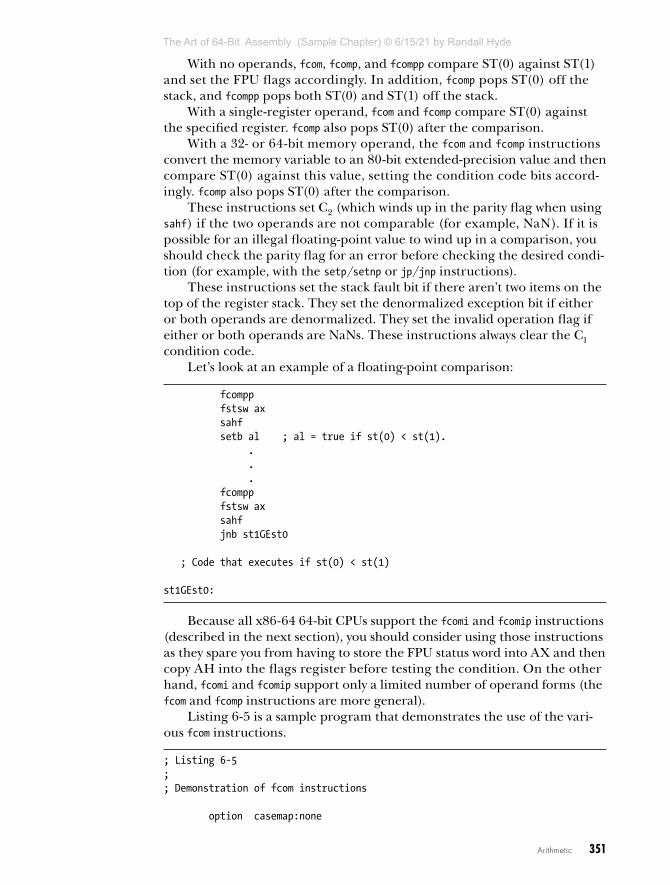
Arithmetic 351
With no operands, fcom, fcomp, and fcompp compare ST(0) against ST(1) and set the FPU flags accordingly. In addition, fcomp pops ST(0) off the stack, and fcompp pops both ST(0) and ST(1) off the stack.
With a single-register operand, fcom and fcomp compare ST(0) against the specified register. fcomp also pops ST(0) after the comparison.
With a 32- or 64-bit memory operand, the fcom and fcomp instructions convert the memory variable to an 80-bit extended-precision value and then compare ST(0) against this value, setting the condition code bits accord-ingly. fcomp also pops ST(0) after the comparison.
These instructions set C2 (which winds up in the parity flag when using sahf) if the two operands are not comparable (for example, NaN). If it is possible for an illegal floating-point value to wind up in a comparison, you should check the parity flag for an error before checking the desired condi-tion (for example, with the setp/setnp or jp/jnp instructions).
These instructions set the stack fault bit if there aren’t two items on the top of the register stack. They set the denormalized exception bit if either or both operands are denormalized. They set the invalid operation flag if either or both operands are NaNs. These instructions always clear the C1 condition code.
Let’s look at an example of a floating-point comparison:
fcompp fstsw ax sahf setb al ; al = true if st(0) < st(1). . . . fcompp fstsw ax sahf jnb st1GEst0
; Code that executes if st(0) < st(1)
st1GEst0:
Because all x86-64 64-bit CPUs support the fcomi and fcomip instructions (described in the next section), you should consider using those instructions as they spare you from having to store the FPU status word into AX and then copy AH into the flags register before testing the condition. On the other hand, fcomi and fcomip support only a limited number of operand forms (the fcom and fcomp instructions are more general).
Listing 6-5 is a sample program that demonstrates the use of the vari-ous fcom instructions.
; Listing 6-5;; Demonstration of fcom instructions
option casemap:none
The Art of 64-Bit Assembly (Sample Chapter) © 6/15/21 by Randall Hyde
T H E A R T O F 6 4 - B I T A S S E M B LY
R A N D A L L H Y D E
6/15/21

352 Chapter 6
nl = 10
.constttlStr byte "Listing 6-5", 0fcomFmt byte "fcom %f < %f is %d", nl, 0fcomFmt2 byte "fcom(2) %f < %f is %d", nl, 0fcomFmt3 byte "fcom st(1) %f < %f is %d", nl, 0fcomFmt4 byte "fcom st(1) (2) %f < %f is %d", nl, 0fcomFmt5 byte "fcom mem %f < %f is %d", nl, 0fcomFmt6 byte "fcom mem %f (2) < %f is %d", nl, 0fcompFmt byte "fcomp %f < %f is %d", nl, 0fcompFmt2 byte "fcomp (2) %f < %f is %d", nl, 0fcompFmt3 byte "fcomp st(1) %f < %f is %d", nl, 0fcompFmt4 byte "fcomp st(1) (2) %f < %f is %d", nl, 0fcompFmt5 byte "fcomp mem %f < %f is %d", nl, 0fcompFmt6 byte "fcomp mem (2) %f < %f is %d", nl, 0fcomppFmt byte "fcompp %f < %f is %d", nl, 0fcomppFmt2 byte "fcompp (2) %f < %f is %d", nl, 0
three real8 3.0zero real8 0.0minusTwo real8 -2.0
.datast0 real8 ?st1 real8 ?
.code externdef printf:proc
; Return program title to C++ program:
public getTitlegetTitle proc lea rax, ttlStr retgetTitle endp
; printFP- Prints values of st0 and (possibly) st1.; Caller must pass in ptr to fmtStr in RCX.
printFP proc sub rsp, 40
; For varargs (for example, printf call), double; values must appear in RDX and R8 rather; than XMM1, XMM2.; Note: if only one double arg in format; string, printf call will ignore 2nd; value in R8.
mov rdx, qword ptr st0 mov r8, qword ptr st1
The Art of 64-Bit Assembly (Sample Chapter) © 6/15/21 by Randall Hyde
T H E A R T O F 6 4 - B I T A S S E M B LY
R A N D A L L H Y D E
6/15/21

Arithmetic 353
movzx r9, al call printf add rsp, 40 retprintFP endp
; Here is the "asmMain" function.
public asmMainasmMain proc push rbp mov rbp, rsp sub rsp, 48 ;Shadow storage
; fcom demo
xor eax, eax fld three fld zero fcom fstsw ax sahf setb al fstp st0 fstp st1 lea rcx, fcomFmt call printFP
; fcom demo 2
xor eax, eax fld zero fld three fcom fstsw ax sahf setb al fstp st0 fstp st1 lea rcx, fcomFmt2 call printFP
; fcom st(i) demo
xor eax, eax fld three fld zero fcom st(1) fstsw ax sahf setb al fstp st0 fstp st1
The Art of 64-Bit Assembly (Sample Chapter) © 6/15/21 by Randall Hyde
T H E A R T O F 6 4 - B I T A S S E M B LY
R A N D A L L H Y D E
6/15/21

354 Chapter 6
lea rcx, fcomFmt3 call printFP
; fcom st(i) demo 2
xor eax, eax fld zero fld three fcom st(1) fstsw ax sahf setb al fstp st0 fstp st1 lea rcx, fcomFmt4 call printFP
; fcom mem64 demo
xor eax, eax fld three ;Never on stack so fstp st1 ; copy for output fld zero fcom three fstsw ax sahf setb al fstp st0 lea rcx, fcomFmt5 call printFP
; fcom mem64 demo 2
xor eax, eax fld zero ;Never on stack so fstp st1 ; copy for output fld three fcom zero fstsw ax sahf setb al fstp st0 lea rcx, fcomFmt6 call printFP
; fcomp demo
xor eax, eax fld zero fld three fst st0 ; Because this gets popped fcomp fstsw ax sahf setb al
The Art of 64-Bit Assembly (Sample Chapter) © 6/15/21 by Randall Hyde
T H E A R T O F 6 4 - B I T A S S E M B LY
R A N D A L L H Y D E
6/15/21

Arithmetic 355
fstp st1 lea rcx, fcompFmt call printFP ; fcomp demo 2
xor eax, eax fld three fld zero fst st0 ; Because this gets popped fcomp fstsw ax sahf setb al fstp st1 lea rcx, fcompFmt2 call printFP
; fcomp demo 3
xor eax, eax fld zero fld three fst st0 ; Because this gets popped fcomp st(1) fstsw ax sahf setb al fstp st1 lea rcx, fcompFmt3 call printFP
; fcomp demo 4
xor eax, eax fld three fld zero fst st0 ; Because this gets popped fcomp st(1) fstsw ax sahf setb al fstp st1 lea rcx, fcompFmt4 call printFP
; fcomp demo 5
xor eax, eax fld three fstp st1 fld zero fst st0 ; Because this gets popped fcomp three fstsw ax
The Art of 64-Bit Assembly (Sample Chapter) © 6/15/21 by Randall Hyde
T H E A R T O F 6 4 - B I T A S S E M B LY
R A N D A L L H Y D E
6/15/21

356 Chapter 6
sahf setb al lea rcx, fcompFmt5 call printFP
; fcomp demo 6
xor eax, eax fld zero fstp st1 fld three fst st0 ; Because this gets popped fcomp zero fstsw ax sahf setb al lea rcx, fcompFmt6 call printFP
; fcompp demo
xor eax, eax fld zero fst st1 ; Because this gets popped fld three fst st0 ; Because this gets popped fcompp fstsw ax sahf setb al lea rcx, fcomppFmt call printFP
; fcompp demo 2
xor eax, eax fld three fst st1 ; Because this gets popped fld zero fst st0 ; Because this gets popped fcompp fstsw ax sahf setb al lea rcx, fcomppFmt2 call printFP
leave ret ;Returns to caller
asmMain endp end
Listing 6-5: Program that demonstrates the fcom instructions
The Art of 64-Bit Assembly (Sample Chapter) © 6/15/21 by Randall Hyde
T H E A R T O F 6 4 - B I T A S S E M B LY
R A N D A L L H Y D E
6/15/21

Arithmetic 357
Here’s the build command and output for the program in Listing 6-5:
C:\>build listing6-5
C:\>echo off Assembling: listing6-5.asmc.cpp
C:\>listing6-5Calling Listing 6-5:fcom 0.000000 < 3.000000 is 1fcom(2) 3.000000 < 0.000000 is 0fcom st(1) 0.000000 < 3.000000 is 1fcom st(1) (2) 3.000000 < 0.000000 is 0fcom mem 0.000000 < 3.000000 is 1fcom mem 3.000000 (2) < 0.000000 is 0fcomp 3.000000 < 0.000000 is 0fcomp (2) 0.000000 < 3.000000 is 1fcomp st(1) 3.000000 < 0.000000 is 0fcomp st(1) (2) 0.000000 < 3.000000 is 1fcomp mem 0.000000 < 3.000000 is 1fcomp mem (2) 3.000000 < 0.000000 is 0fcompp 3.000000 < 0.000000 is 0fcompp (2) 0.000000 < 3.000000 is 1Listing 6-5 terminated
NO T E The x87 FPU also provides instructions that do unordered comparisons: fucom, fucomp, and fucompp. These are functionally equivalent to fcom, fcomp, and fcompp except they raise an exception under different conditions. See the Intel documentation for more details.
6.5.9.2 The fcomi and fcomip Instructions
The fcomi and fcomip instructions compare ST(0) to the specified operand and set the corresponding EFLAGS condition code bits based on the result of the comparison. You use these instructions in a similar manner to fcom and fcomp except you can test the CPU’s flag bits directly after the execu-tion of these instructions without first moving the FPU status bits into the EFLAGS register. The legal forms for these instructions are as follows:
fcomi st(0), st(i)fcomip st(0), st(i)
Note that a pop-pop version (fcomipp) does not exist. If all you want to do is compare the top two items on the FPU stack, you will have to explicitly pop that item yourself (for example, by using the fstp st(0) instruction).
Listing 6-6 is a sample program that demonstrates the operation of the fcomi and fcomip instructions.
; Listing 6-6;
The Art of 64-Bit Assembly (Sample Chapter) © 6/15/21 by Randall Hyde
T H E A R T O F 6 4 - B I T A S S E M B LY
R A N D A L L H Y D E
6/15/21

358 Chapter 6
; Demonstration of fcomi and fcomip instructions
option casemap:none
nl = 10
.constttlStr byte "Listing 6-6", 0fcomiFmt byte "fcomi %f < %f is %d", nl, 0fcomiFmt2 byte "fcomi(2) %f < %f is %d", nl, 0fcomipFmt byte "fcomip %f < %f is %d", nl, 0fcomipFmt2 byte "fcomip (2) %f < %f is %d", nl, 0
three real8 3.0zero real8 0.0minusTwo real8 -2.0
.datast0 real8 ?st1 real8 ?
.code externdef printf:proc
; Return program title to C++ program:
public getTitlegetTitle proc lea rax, ttlStr retgetTitle endp
; printFP- Prints values of st0 and (possibly) st1.; Caller must pass in ptr to fmtStr in RCX.
printFP proc sub rsp, 40
; For varargs (for example, printf call), double; values must appear in RDX and R8 rather; than XMM1, XMM2.; Note: if only one double arg in format; string, printf call will ignore 2nd; value in R8.
mov rdx, qword ptr st0 mov r8, qword ptr st1 movzx r9, al call printf add rsp, 40 ret
The Art of 64-Bit Assembly (Sample Chapter) © 6/15/21 by Randall Hyde
T H E A R T O F 6 4 - B I T A S S E M B LY
R A N D A L L H Y D E
6/15/21

Arithmetic 359
printFP endp
; Here is the "asmMain" function.
public asmMainasmMain proc push rbp mov rbp, rsp sub rsp, 48 ; Shadow storage
; Test to see if 0 < 3; Note: ST(0) contains 0, ST(1) contains 3
xor eax, eax fld three fld zero fcomi st(0), st(1) setb al fstp st0 fstp st1 lea rcx, fcomiFmt call printFP
; Test to see if 3 < 0; Note: ST(0) contains 0, ST(1) contains 3
xor eax, eax fld zero fld three fcomi st(0), st(1) setb al fstp st0 fstp st1 lea rcx, fcomiFmt2 call printFP ; Test to see if 3 < 0; Note: ST(0) contains 0, ST(1) contains 3
xor eax, eax fld zero fld three fst st0 ; Because this gets popped fcomip st(0), st(1) setb al fstp st1 lea rcx, fcomipFmt call printFP
; Test to see if 0 < 3; Note: ST(0) contains 0, ST(1) contains 3
The Art of 64-Bit Assembly (Sample Chapter) © 6/15/21 by Randall Hyde
T H E A R T O F 6 4 - B I T A S S E M B LY
R A N D A L L H Y D E
6/15/21

360 Chapter 6
xor eax, eax fld three fld zero fst st0 ; Because this gets popped fcomip st(0), st(1) setb al fstp st1 lea rcx, fcomipFmt2 call printFP
leave ret ; Returns to caller
asmMain endp end
Listing 6-6: Sample program demonstrating floating-point comparisons
Here’s the build command and output for the program in Listing 6-6:
C:\>build listing6-6
C:\>echo off Assembling: listing6-6.asmc.cpp
C:\>listing6-6Calling Listing 6-6:fcomi 0.000000 < 3.000000 is 1fcomi(2) 3.000000 < 0.000000 is 0fcomip 3.000000 < 0.000000 is 0fcomip (2) 0.000000 < 3.000000 is 1Listing 6-6 terminated
NO T E The x87 FPU also provides two instructions that do unordered comparisons: fucomi and fucomip. These are functionally equivalent to fcomi and fcomip except they raise an exception under different conditions. See the Intel documentation for more details.
6.5.9.3 The ftst Instruction
The ftst instruction compares the value in ST(0) against 0.0. It behaves just like the fcom instruction would if ST(1) contained 0.0. This instruction does not differentiate –0.0 from +0.0. If the value in ST(0) is either of these val-ues, ftst will set C3 to denote equality (or unordered). This instruction does not pop ST(0) off the stack.
Here’s an example:
ftstfstsw ax sahfsete al ; Set al to 1 if TOS = 0.0
The Art of 64-Bit Assembly (Sample Chapter) © 6/15/21 by Randall Hyde
T H E A R T O F 6 4 - B I T A S S E M B LY
R A N D A L L H Y D E
6/15/21

Arithmetic 361
6.5.10 Constant InstructionsThe FPU provides several instructions that let you load commonly used con-stants onto the FPU’s register stack. These instructions set the stack fault, invalid operation, and C1 flags if a stack overflow occurs; they do not other-wise affect the FPU flags. The specific instructions in this category include the following:
fldz ; Pushes +0.0.fld1 ; Pushes +1.0.fldpi ; Pushes pi (3.15159...)fldl2t ; Pushes log2(10).fldl2e ; Pushes log2(e).fldlg2 ; Pushes log10(2).fldln2 ; Pushes ln(2).
6.5.11 Transcendental InstructionsThe FPU provides eight transcendental (logarithmic and trigonometric) instructions to compute sine, cosine, partial tangent, partial arctangent, 2x – 1, y × log2(x), and y × log2(x + 1). Using various algebraic identities, it is easy to compute most of the other common transcendental functions by using these instructions.
6.5.11.1 The f2xm1 Instruction
f2xm1 computes 2ST(0) – 1. The value in ST(0) must be in the range –1.0 to +1.0. If ST(0) is out of range, f2xm1 generates an undefined result but raises no exceptions. The computed value replaces the value in ST(0).
Here’s an example computing 10i using the identity 10i = 2i×log2(10). This is useful for only a small range of i that doesn’t put ST(0) outside the previ-ously mentioned valid range:
fld ifldl2tfmulf2xm1fld1fadd
Because f2xm1 computes 2x – 1, the preceding code adds 1.0 to the result at the end of the computation.
6.5.11.2 The fsin, fcos, and fsincos Instructions
These instructions pop the value off the top of the register stack and com-pute the sine, cosine, or both, and push the result(s) back onto the stack. The fsincos instruction pushes the sine followed by the cosine of the origi-nal operand; hence it leaves cos(ST(0)) in ST(0) and sin(ST(0)) in ST(1).
These instructions assume ST(0) specifies an angle in radians, and this angle must be in the range –263 < ST(0) < +263. If the original operand is out
The Art of 64-Bit Assembly (Sample Chapter) © 6/15/21 by Randall Hyde
T H E A R T O F 6 4 - B I T A S S E M B LY
R A N D A L L H Y D E
6/15/21

362 Chapter 6
of range, these instructions set the C2 flag and leave ST(0) unchanged. You can use the fprem1 instruction, with a divisor of 2π, to reduce the operand to a reasonable range.
These instructions set the stack fault (or rounding)/C1, precision, underflow, denormalized, and invalid operation flags according to the result of the computation.
6.5.11.3 The fptan Instruction
fptan computes the tangent of ST(0), replaces ST(0) with this value, and then pushes 1.0 onto the stack. Like the fsin and fcos instructions, the value of ST(0) must be in radians and in the range –263 < ST(0) < +263. If the value is outside this range, fptan sets C2 to indicate that the conversion did not take place. As with the fsin, fcos, and fsincos instructions, you can use the fprem1 instruction to reduce this operand to a reasonable range by using a divisor of 2π.
If the argument is invalid (that is, 0 or π radians, which causes a divi-sion by 0), the result is undefined and this instruction raises no exceptions. fptan will set the stack fault/rounding, precision, underflow, denormal, invalid operation, C2, and C1 bits as required by the operation.
6.5.11.4 The fpatan Instruction
fpatan expects two values on the top of stack. It pops them and computes ST(0) = tan-1(ST(1) / ST(0)). The resulting value is the arctangent of the ratio on the stack expressed in radians. If you want to compute the arctan-gent of a particular value, use fld1 to create the appropriate ratio and then execute the fpatan instruction.
This instruction affects the stack fault/C1, precision, underflow, denor-mal, and invalid operation bits if a problem occurs during the computation. It sets the C1 condition code bit if it has to round the result.
6.5.11.5 The fyl2x Instruction
The fyl2x instruction computes ST(0) = ST(1) × log2(ST(0)). The instruction itself has no operands, but expects two operands on the FPU stack in ST(1) and ST(0), thus using the following syntax:
fyl2x
To compute the log of any other base, you can use the following arith-metic identity:
logn(x) = log2(x) / log2(n)So if you first compute log2(n) and put its reciprocal on the stack, then
push x onto the stack and execute fyl2x, you wind up with logn(x).The fyl2x instruction sets the C1 condition code bit if it has to round
up the value. It clears C1 if no rounding occurs or if a stack overflow occurs. The remaining floating-point condition codes are undefined after the exe-cution of this instruction. fyl2x can raise the following floating-point excep-tions: invalid operation, denormal result, overflow, underflow, and inexact
The Art of 64-Bit Assembly (Sample Chapter) © 6/15/21 by Randall Hyde
T H E A R T O F 6 4 - B I T A S S E M B LY
R A N D A L L H Y D E
6/15/21

Arithmetic 363
result. Note that the fldl2t and fldl2e instructions turn out to be quite handy when using the fyl2x instruction (for computing log10 and ln).
6.5.11.6 The fyl2xp1 Instruction
fyl2xp1 computes ST(0) = ST(1) × log2(ST(0) + 1.0), from two operands on the FPU stack. The syntax for this instruction is as follows:
fyl2xp1
Otherwise, the instruction is identical to fyl2x.
6.5.12 Miscellaneous InstructionsThe FPU includes several additional instructions that control the FPU, syn-chronize operations, and let you test or set various status bits: finit/fninit, fldcw, fstcw, fclex/fnclex, and fstsw.
6.5.12.1 The finit and fninit Instructions
The finit and fninit instructions initialize the FPU for proper operation. Your code should execute one of these instructions before executing any other FPU instructions. They initialize the control register to 37Fh, the status register to 0, and the tag word to 0FFFFh. The other registers are unaffected.
Here are some examples:
finitfninit
The difference between finit and fninit is that finit first checks for any pending floating-point exceptions before initializing the FPU; fninit does not.
6.5.12.2 The fldcw and fstcw Instructions
The fldcw and fstcw instructions require a single 16-bit memory operand:
fldcw mem16fstcw mem16
These two instructions load the control word from a memory location (fldcw) or store the control word to a 16-bit memory location (fstcw).
When using fldcw to turn on one of the exceptions, if the corresponding exception flag is set when you enable that exception, the FPU will gener-ate an immediate interrupt before the CPU executes the next instruction. Therefore, you should use fclex to clear any pending interrupts before changing the FPU exception enable bits.
6.5.12.3 The fclex and fnclex Instructions
The fclex and fnclex instructions clear all exception bits, the stack fault bit, and the busy flag in the FPU status register.
The Art of 64-Bit Assembly (Sample Chapter) © 6/15/21 by Randall Hyde
T H E A R T O F 6 4 - B I T A S S E M B LY
R A N D A L L H Y D E
6/15/21

364 Chapter 6
Here are examples:
fclexfnclex
The difference between these instructions is the same as between finit and fninit: fclex first checks for pending floating-point exceptions.
6.5.12.4 The fstsw and fnstsw Instructions
These instructions store the FPU status word into a 16-bit memory location or the AX register:
fstsw axfnstsw axfstsw mem16fnstsw mem16
These instructions are unusual in the sense that they can copy an FPU value into one of the x86-64 general-purpose registers (specifically, AX). The purpose is to allow the CPU to easily test the condition code register with the sahf instruction. The difference between fstsw and fnstsw is the same as for fclex and fnclex.
6.6 Converting Floating-Point Expressions to Assembly LanguageBecause the FPU register organization is different from the x86-64 integer register set, translating arithmetic expressions involving floating-point oper-ands is a little different from translating integer expressions. Therefore, it makes sense to spend some time discussing how to manually translate float-ing-point expressions into assembly language.
The FPU uses postfix notation (also called reverse Polish notation, or RPN), for arithmetic operations. Once you get used to using postfix notation, it’s actually a bit more convenient for translating expressions because you don’t have to worry about allocating temporary variables—they always wind up on the FPU stack. Postfix notation, as opposed to standard infix notation, places the operands before the operator. Table 6-14 provides simple examples of infix notation and the corresponding postfix notation.
Table 6-14: Infix-to-Postfix Translation
Infix notation Postfix notation
5 + 6 5 6 +
7 – 2 7 2 –
x × y x y ×
a / b a b /
The Art of 64-Bit Assembly (Sample Chapter) © 6/15/21 by Randall Hyde
T H E A R T O F 6 4 - B I T A S S E M B LY
R A N D A L L H Y D E
6/15/21

Arithmetic 365
A postfix expression like 5 6 + says, “Push 5 onto the stack, push 6 onto the stack, and then pop the value off the top of stack (6) and add it to the new top of stack.” Sound familiar? This is exactly what the fld and fadd instructions do. In fact, you can calculate the result by using the following code:
fld five ; Declared somewhere as five real8 5.0 (or real4/real10)fld six ; Declared somewhere as six real8 6.0 (or real4/real10)fadd ; 11.0 is now on the top of the FPU stack.
As you can see, postfix is a convenient notation because it’s easy to translate this code into FPU instructions.
Another advantage to postfix notation is that it doesn’t require any parentheses. The examples in Table 6-15 demonstrate some slightly more complex infix-to-postfix conversions.
Table 6-15: More-Complex Infix-to-Postfix Translations
Infix notation Postfix notation
(x + y) × 2 x y + 2 ×
x × 2 – (a + b) x 2 × a b + –
(a + b) × (c + d) a b + c d + ×
The postfix expression x y + 2 × says, “Push x, then push y; next, add those values on the stack (producing x + y on the stack). Next, push 2 and then multiply the two values (2 and x + y) on the stack to produce two times the quantity x + y.” Once again, we can translate these postfix expressions directly into assembly language. The following code demonstrates the con-version for each of the preceding expressions:
; x y + 2 *
fld x fld y fadd fld const2 ;const2 real8 2.0 in .data section fmul
; x 2 * a b + -
fld x fld const2 ;const2 real8 2.0 in .data section fmul fld a fld b fadd fsub
; a b + c d + *
The Art of 64-Bit Assembly (Sample Chapter) © 6/15/21 by Randall Hyde
T H E A R T O F 6 4 - B I T A S S E M B LY
R A N D A L L H Y D E
6/15/21
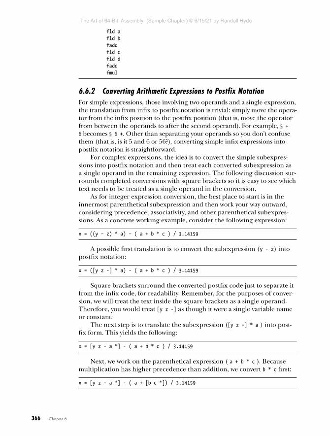
366 Chapter 6
fld a fld b fadd fld c fld d fadd fmul
6.6.2 Converting Arithmetic Expressions to Postfix NotationFor simple expressions, those involving two operands and a single expression, the translation from infix to postfix notation is trivial: simply move the opera-tor from the infix position to the postfix position (that is, move the operator from between the operands to after the second operand). For example, 5 + 6 becomes 5 6 +. Other than separating your operands so you don’t confuse them (that is, is it 5 and 6 or 56?), converting simple infix expressions into postfix notation is straightforward.
For complex expressions, the idea is to convert the simple subexpres-sions into postfix notation and then treat each converted subexpression as a single operand in the remaining expression. The following discussion sur-rounds completed conversions with square brackets so it is easy to see which text needs to be treated as a single operand in the conversion.
As for integer expression conversion, the best place to start is in the innermost parenthetical subexpression and then work your way outward, considering precedence, associativity, and other parenthetical subexpres-sions. As a concrete working example, consider the following expression:
x = ((y – z) * a) – ( a + b * c ) / 3.14159
A possible first translation is to convert the subexpression (y - z) into postfix notation:
x = ([y z -] * a) - ( a + b * c ) / 3.14159
Square brackets surround the converted postfix code just to separate it from the infix code, for readability. Remember, for the purposes of conver-sion, we will treat the text inside the square brackets as a single operand. Therefore, you would treat [y z -] as though it were a single variable name or constant.
The next step is to translate the subexpression ([y z -] * a ) into post-fix form. This yields the following:
x = [y z - a *] - ( a + b * c ) / 3.14159
Next, we work on the parenthetical expression ( a + b * c ). Because multiplication has higher precedence than addition, we convert b * c first:
x = [y z - a *] - ( a + [b c *]) / 3.14159
The Art of 64-Bit Assembly (Sample Chapter) © 6/15/21 by Randall Hyde
T H E A R T O F 6 4 - B I T A S S E M B LY
R A N D A L L H Y D E
6/15/21
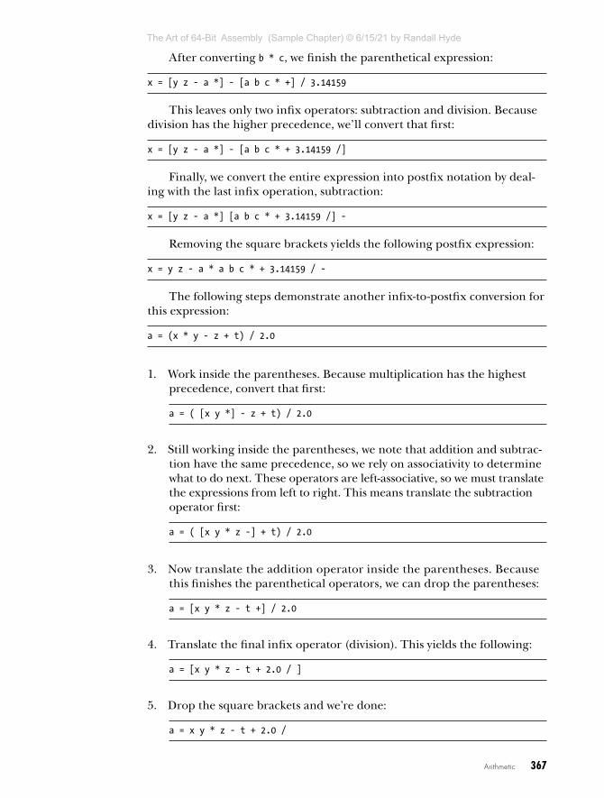
Arithmetic 367
After converting b * c, we finish the parenthetical expression:
x = [y z - a *] - [a b c * +] / 3.14159
This leaves only two infix operators: subtraction and division. Because division has the higher precedence, we’ll convert that first:
x = [y z - a *] - [a b c * + 3.14159 /]
Finally, we convert the entire expression into postfix notation by deal-ing with the last infix operation, subtraction:
x = [y z - a *] [a b c * + 3.14159 /] -
Removing the square brackets yields the following postfix expression:
x = y z - a * a b c * + 3.14159 / -
The following steps demonstrate another infix-to-postfix conversion for this expression:
a = (x * y - z + t) / 2.0
1. Work inside the parentheses. Because multiplication has the highest precedence, convert that first:
a = ( [x y *] - z + t) / 2.0
2. Still working inside the parentheses, we note that addition and subtrac-tion have the same precedence, so we rely on associativity to determine what to do next. These operators are left-associative, so we must translate the expressions from left to right. This means translate the subtraction operator first:
a = ( [x y * z -] + t) / 2.0
3. Now translate the addition operator inside the parentheses. Because this finishes the parenthetical operators, we can drop the parentheses:
a = [x y * z - t +] / 2.0
4. Translate the final infix operator (division). This yields the following:
a = [x y * z - t + 2.0 / ]
5. Drop the square brackets and we’re done:
a = x y * z - t + 2.0 /
The Art of 64-Bit Assembly (Sample Chapter) © 6/15/21 by Randall Hyde
T H E A R T O F 6 4 - B I T A S S E M B LY
R A N D A L L H Y D E
6/15/21

368 Chapter 6
6.6.3 Converting Postfix Notation to Assembly LanguageOnce you’ve translated an arithmetic expression into postfix notation, finishing the conversion to assembly language is easy. All you have to do is issue an fld instruction whenever you encounter an operand and issue an appropriate arithmetic instruction when you encounter an operator. This section uses the completed examples from the previous section to demon-strate how little there is to this process.
x = y z - a * a b c * + 3.14159 / -
1. Convert y to fld y.
2. Convert z to fld z.
3. Convert - to fsub.
4. Convert a to fld a.
5. Convert * to fmul.
6. Continuing in a left-to-right fashion, generate the following code for the expression:
fld yfld zfsubfld afmulfld afld bfld cfmulfaddfldpi ; Loads pi (3.14159)fdivfsub
fstp x ; Store result away into x.
Here’s the translation for the second example in the previous section:
a = x y * z - t + 2.0 / fld x fld y fmul fld z fsub fld t fadd fld const2 ;const2 real8 2.0 in .data section fdiv
fstp a ; Store result away into a.
The Art of 64-Bit Assembly (Sample Chapter) © 6/15/21 by Randall Hyde
T H E A R T O F 6 4 - B I T A S S E M B LY
R A N D A L L H Y D E
6/15/21

Arithmetic 369
As you can see, the translation is fairly simple once you’ve converted the infix notation to postfix notation. Also note that, unlike integer expression conversion, you don’t need any explicit temporaries. It turns out that the FPU stack provides the temporaries for you.9 For these reasons, converting floating-point expressions into assembly language is actually easier than converting integer expressions.
6.7 SSE Floating-Point ArithmeticAlthough the x87 FPU is relatively easy to use, the stack-based design of the FPU created performance bottlenecks as CPUs became more powerful. After introducing the Streaming SIMD Extensions (SSE) in its Pentium III CPUs (way back in 1999), Intel decided to resolve the FPU performance bottleneck and added scalar (non-vector) floating-point instructions to the SSE instruction set that could use the XMM registers. Most modern programs favor the use of the SSE (and later) registers and instructions for floating-point operations over the x87 FPU, using only those x87 operations available exclusively on the x87.
The SSE instruction set supports two floating-point data types: 32-bit single-precision (Intel calls these scalar single operations) and 64-bit dou-ble-precision values (Intel calls these scalar double operations).10 The SSE does not support the 80-bit extended-precision floating-point data types of the x87 FPU. If you need the extended-precision format, you’ll have to use the x87 FPU.
6.7.1 SSE MXCSR RegisterThe SSE MXCSR register is a 32-bit status and control register that controls SSE floating-point operations. Bits 16 to 32 are reserved and currently have no meaning. Table 6-16 lists the functions of the LO 16 bits.
Table 6-16: SSE MXCSR Register
Bit Name Function
0 IE Invalid operation exception flag. Set if an invalid operation was attempted.
1 DE Denormal exception flag. Set if operations produced a denormalized value.
2 ZE Zero exception flag. Set if an attempt to divide by 0 was made.
3 OE Overflow exception flag. Set if there was an overflow.
9. This assumes, of course, that your calculations aren’t so complex that you exceed the eight-element limitation of the FPU stack.
10. This book has typically used scalar to denote atomic (noncomposite) data types that were not floating-point (chars, Booleans, integers, and so forth). In fact, floating-point values (that are not part of a larger composite data type) are also scalars. Intel uses scalar as opposed to vector (the SSE also supports vector operations).
continued
The Art of 64-Bit Assembly (Sample Chapter) © 6/15/21 by Randall Hyde
T H E A R T O F 6 4 - B I T A S S E M B LY
R A N D A L L H Y D E
6/15/21

370 Chapter 6
Bit Name Function
4 UE Underflow exception flag. Set if there was an underflow.
5 PE Precision exception flag. Set if there was a precision exception.
6 DAZ Denormals are 0. If set, treat denormalized values as 0.
7 IM Invalid operation mask. If set, ignore invalid operation exceptions.
8 DM Denormal mask. If set, ignore denormal exceptions.
9 ZM Divide-by-zero mask. If set, ignore division-by-zero exceptions.
10 OM Overflow mask. If set, ignore overflow exceptions.
11 UM Underflow mask. If set, ignore underflow exceptions.
12 PM Precision mask. If set, ignore precision exceptions.
13 RoundingControl
00: Round to nearest 01: Round toward –infinity10: Round toward +infinity 11: Round toward 0 (truncate)
14
15 FTZ Flush to zero. When set, all underflow conditions set the register to 0.
Access to the SSE MXCSR register is via the following two instructions:
ldmxcsr mem32stmxcsr mem32
The ldmxcsr instruction loads the MXCSR register from the specified 32-bit memory location. The stmxcsr instruction stores the current contents of the MXCSR register to the specified memory location.
By far, the most common use of these two instructions is to set the round-ing mode. In typical programs using the SSE floating-point instructions, it is common to switch between the round-to-nearest and round-to-zero (trun-cate) modes.
6.7.2 SSE Floating-Point Move InstructionsThe SSE instruction set provides two instructions to move floating-point values between XMM registers and memory: movss (move scalar single) and movsd (move scalar double). Here is their syntax:
movss xmmn, mem32movss mem32, xmmnmovsd xmmn, mem64movsd mem64, xmmn
As for the standard general-purpose registers, the movss and movsd instructions move data between an appropriate memory location (contain-ing a 32- or 64-bit floating-point value) and one of the 16 XMM registers (XMM0 to XMM15).
The Art of 64-Bit Assembly (Sample Chapter) © 6/15/21 by Randall Hyde
T H E A R T O F 6 4 - B I T A S S E M B LY
R A N D A L L H Y D E
6/15/21

Arithmetic 371
For maximum performance, movss memory operands should appear at a double-word-aligned memory address, and movsd memory operands should appear at a quad-word-aligned memory address. Though these instructions will function properly if the memory operands are not properly aligned in memory, there is a performance hit for misaligned accesses.
In addition to the movss and movsd instructions that move floating-point values between XMM registers or XMM registers and memory, you’ll find a couple of other SSE move instructions useful that move data between XMM and general-purpose registers, movd and movq:
movd reg32, xmmnmovd xmmn, reg32movq reg64, xmmnmovq xmmn, reg64
These instructions also have a form that allows a source memory oper-and. However, you should use movss and movsd to move floating-point variables into XMM registers.
The movq and movd instructions are especially useful for copying XMM registers into 64-bit general-purpose registers prior to a call to printf() (when printing floating-point values). As you’ll see in a few sections, these instructions are also useful for floating-point comparisons on the SSE.
6.7.3 SSE Floating-Point Arithmetic InstructionsThe Intel SSE instruction set adds the following floating-point arithmetic instructions:
addss xmmn, xmmnaddss xmmn, mem32addsd xmmn, xmmnaddsd xmmn, mem64
subss xmmn, xmmnsubss xmmn, mem32subsd xmmn, xmmnsubsd xmmn, mem64
mulss xmmn, xmmnmulss xmmn, mem32mulsd xmmn, xmmnmulsd xmmn, mem64
divss xmmn, xmmndivss xmmn, mem32divsd xmmn, xmmndivsd xmmn, mem64
minss xmmn, xmmnminss xmmn, mem32minsd xmmn, xmmnminsd xmmn, mem64
The Art of 64-Bit Assembly (Sample Chapter) © 6/15/21 by Randall Hyde
T H E A R T O F 6 4 - B I T A S S E M B LY
R A N D A L L H Y D E
6/15/21
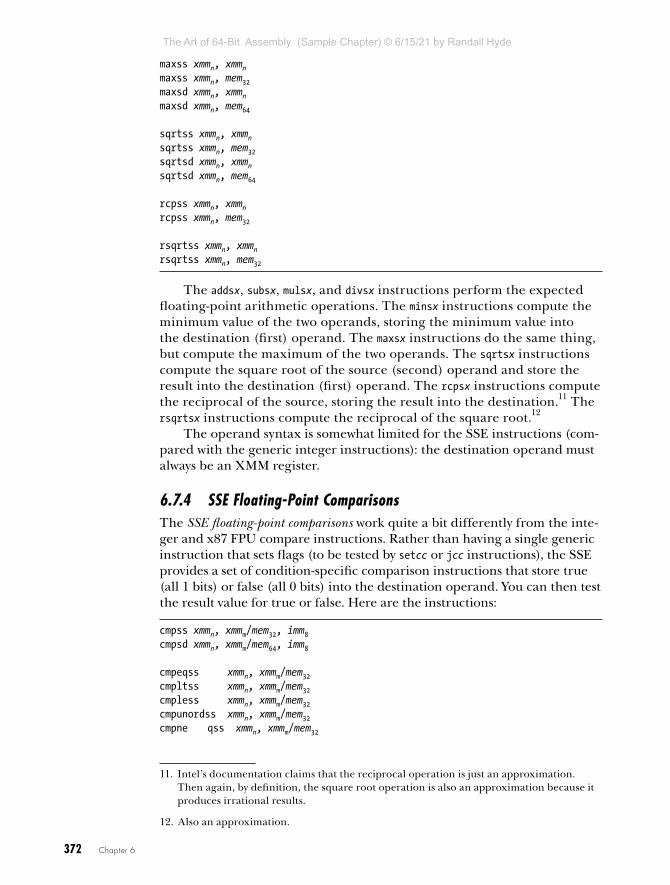
372 Chapter 6
maxss xmmn, xmmnmaxss xmmn, mem32maxsd xmmn, xmmnmaxsd xmmn, mem64
sqrtss xmmn, xmmnsqrtss xmmn, mem32sqrtsd xmmn, xmmnsqrtsd xmmn, mem64
rcpss xmmn, xmmnrcpss xmmn, mem32
rsqrtss xmmn, xmmnrsqrtss xmmn, mem32
The addsx, subsx, mulsx, and divsx instructions perform the expected floating-point arithmetic operations. The minsx instructions compute the minimum value of the two operands, storing the minimum value into the destination (first) operand. The maxsx instructions do the same thing, but compute the maximum of the two operands. The sqrtsx instructions compute the square root of the source (second) operand and store the result into the destination (first) operand. The rcpsx instructions compute the reciprocal of the source, storing the result into the destination.11 The rsqrtsx instructions compute the reciprocal of the square root.12
The operand syntax is somewhat limited for the SSE instructions (com-pared with the generic integer instructions): the destination operand must always be an XMM register.
6.7.4 SSE Floating-Point ComparisonsThe SSE floating-point comparisons work quite a bit differently from the inte-ger and x87 FPU compare instructions. Rather than having a single generic instruction that sets flags (to be tested by setcc or jcc instructions), the SSE provides a set of condition-specific comparison instructions that store true (all 1 bits) or false (all 0 bits) into the destination operand. You can then test the result value for true or false. Here are the instructions:
cmpss xmmn, xmmm/mem32, imm8cmpsd xmmn, xmmm/mem64, imm8
cmpeqss xmmn, xmmm/mem32cmpltss xmmn, xmmm/mem32cmpless xmmn, xmmm/mem32cmpunordss xmmn, xmmm/mem32cmpne qss xmmn, xmmm/mem32
11. Intel’s documentation claims that the reciprocal operation is just an approximation. Then again, by definition, the square root operation is also an approximation because it produces irrational results.
12. Also an approximation.
The Art of 64-Bit Assembly (Sample Chapter) © 6/15/21 by Randall Hyde
T H E A R T O F 6 4 - B I T A S S E M B LY
R A N D A L L H Y D E
6/15/21

Arithmetic 373
cmpnltss xmmn, xmmm/mem32cmpnless xmmn, xmmm/mem32cmpordss xmmn, xmmm/mem32
cmpeqsd xmmn, xmmm/mem64cmpltsd xmmn, xmmm/mem64cmplesd xmmn, xmmm/mem64cmpunordsd xmmn, xmmm/mem64cmpneqsd xmmn, xmmm/mem64cmpnltsd xmmn, xmmm/mem64cmpnlesd xmmn, xmmm/mem64cmpordsd xmmn, xmmm/mem64
The immediate constant is a value in the range 0 to 7 and represents one of the comparisons in Table 6-17.
Table 6-17: SSE Compare Immediate Operand
imm8 Comparison
0 First operand == second operand
1 First operand < second operand
2 First operand <= second operand
3 First operand unordered second operand
4 First operand != second operand
5 First operand not less than second operand (>=)
6 First operand not less than or equal to second operand (>)
7 First operand ordered second operand
The instructions without the third (immediate) operand are special pseudo-ops MASM provides that automatically supply the appropriate third operand. You can use the nlt form for ge and nle form for gt, assuming the operands are ordered.
The unordered comparison returns true if either (or both) operands are unordered (typically, NaN values). Likewise, the ordered comparison returns true if both operands are ordered.
As noted, these instructions leave 0 or all 1 bits in the destination register to represent false or true. If you want to branch based on these conditions, you should move the destination XMM register into a general-purpose register and test that register for zero/not zero. You can use the movq or movd instructions to accomplish this:
cmpeqsd xmm0, xmm1 movd eax, xmm0 ;move true/false to EAX test eax, eax ;Test for true/false jnz xmm0EQxmm1 ;Branch if xmm0 == xmm1
; code to execute if xmm0 != xmm1
The Art of 64-Bit Assembly (Sample Chapter) © 6/15/21 by Randall Hyde
T H E A R T O F 6 4 - B I T A S S E M B LY
R A N D A L L H Y D E
6/15/21
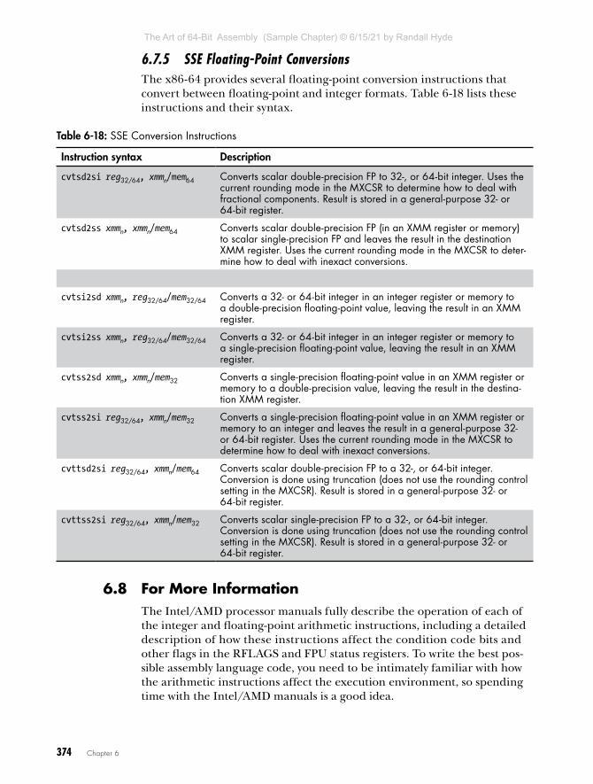
374 Chapter 6
6.7.5 SSE Floating-Point ConversionsThe x86-64 provides several floating-point conversion instructions that convert between floating-point and integer formats. Table 6-18 lists these instructions and their syntax.
Table 6-18: SSE Conversion Instructions
Instruction syntax Description
cvtsd2si reg32/64, xmmn/mem64 Converts scalar double-precision FP to 32-, or 64-bit integer. Uses the current rounding mode in the MXCSR to determine how to deal with fractional components. Result is stored in a general-purpose 32- or 64-bit register.
cvtsd2ss xmmn, xmmn/mem64 Converts scalar double-precision FP (in an XMM register or memory) to scalar single-precision FP and leaves the result in the destination XMM register. Uses the current rounding mode in the MXCSR to deter-mine how to deal with inexact conversions.
cvtsi2sd xmmn, reg32/64/mem32/64 Converts a 32- or 64-bit integer in an integer register or memory to a double-precision floating-point value, leaving the result in an XMM register.
cvtsi2ss xmmn, reg32/64/mem32/64 Converts a 32- or 64-bit integer in an integer register or memory to a single-precision floating-point value, leaving the result in an XMM register.
cvtss2sd xmmn, xmmn/mem32 Converts a single-precision floating-point value in an XMM register or memory to a double-precision value, leaving the result in the destina-tion XMM register.
cvtss2si reg32/64, xmmn/mem32 Converts a single-precision floating-point value in an XMM register or memory to an integer and leaves the result in a general-purpose 32- or 64-bit register. Uses the current rounding mode in the MXCSR to determine how to deal with inexact conversions.
cvttsd2si reg32/64, xmmn/mem64 Converts scalar double-precision FP to a 32-, or 64-bit integer. Conversion is done using truncation (does not use the rounding control setting in the MXCSR). Result is stored in a general-purpose 32- or 64-bit register.
cvttss2si reg32/64, xmmn/mem32 Converts scalar single-precision FP to a 32-, or 64-bit integer. Conversion is done using truncation (does not use the rounding control setting in the MXCSR). Result is stored in a general-purpose 32- or 64-bit register.
6.8 For More InformationThe Intel/AMD processor manuals fully describe the operation of each of the integer and floating-point arithmetic instructions, including a detailed description of how these instructions affect the condition code bits and other flags in the RFLAGS and FPU status registers. To write the best pos-sible assembly language code, you need to be intimately familiar with how the arithmetic instructions affect the execution environment, so spending time with the Intel/AMD manuals is a good idea.
The Art of 64-Bit Assembly (Sample Chapter) © 6/15/21 by Randall Hyde
T H E A R T O F 6 4 - B I T A S S E M B LY
R A N D A L L H Y D E
6/15/21

Arithmetic 375
Chapter 8 discusses multiprecision integer arithmetic. See that chapter for details on handling integer operands that are greater than 64 bits in size.
The x86-64 SSE instruction set found on later iterations of the CPU provides support for floating-point arithmetic using the AVX register set. Consult the Intel/AMD documentation for details concerning the AVX floating-point instruction set.
6.9 Test Yourself1. What are the implied operands for the single-operand imul and mul
instructions?
2. What is the result size for an 8-bit mul operation? A 16-bit mul operation? A 32-bit mul operation? A 64-bit mul operation? Where does the CPU put the products?
3. What result(s) does an x86 div instruction produce?
4. When performing a signed 16-bit by 16-bit division using idiv, what must you do before executing the idiv instruction?
5. When performing an unsigned 32-bit by 32-bit division using div, what must you do before executing the div instruction?
6. What are the two conditions that will cause a div instruction to produce an exception?
7. How do the mul and imul instructions indicate overflow?
8. How do the mul and imul instructions affect the zero flag?
9. What is the difference between the extended-precision (single operand) imul instruction and the more generic (multi-operand) imul instruction?
10. What instructions would you normally use to sign-extend the accumula-tor prior to executing an idiv instruction?
11. How do the div and idiv instructions affect the carry, zero, overflow, and sign flags?
12. How does the cmp instruction affect the zero flag?
13. How does the cmp instruction affect the carry flag (with respect to an unsigned comparison)?
14. How does the cmp instruction affect the sign and overflow flags (with respect to a signed comparison)?
15. What operands do the setcc instructions take?
16. What do the setcc instructions do to their operand?
17. What is the difference between the test instruction and the and instruction?
18. What are the similarities between the test instruction and the and instruction?
19. Explain how you would use the test instruction to see if an individual bit is 1 or 0 in an operand?
The Art of 64-Bit Assembly (Sample Chapter) © 6/15/21 by Randall Hyde
T H E A R T O F 6 4 - B I T A S S E M B LY
R A N D A L L H Y D E
6/15/21

376 Chapter 6
20. Convert the following expressions to assembly language (assume all variables are signed 32-bit integers):
x = x + yx = y – zx = y * zx = y + z * tx = (y + z) * tx = -((x * y) / z)x = (y == z) && (t != 0)
21. Compute the following expressions without using an imul or mul instruc-tion (assume all variables are signed 32-bit integers):
x = x * 2x = y * 5x = y * 8
22. Compute the following expressions without using a div or idiv instruc-tion (assume all variables are unsigned 16-bit integers):
x = x / 2x = y / 8x = z / 10
23. Convert the following expressions to assembly language by using the FPU (assume all variables are real8 floating-point values):
x = x + yx = y – zx = y * zx = y + z * tx = (y + z) * tx = -((x * y) / z)
24. Convert the following expressions to assembly language by using SSE instructions (assume all variables are real4 floating-point values):
x = x + yx = y – zx = y * zx = y + z * t
25. Convert the following expressions to assembly language by using FPU instructions; assume b is a one-byte Boolean variable and x, y, and z are real8 floating-point variables:
b = x < yb = x >= y && x < z
The Art of 64-Bit Assembly (Sample Chapter) © 6/15/21 by Randall Hyde
T H E A R T O F 6 4 - B I T A S S E M B LY
R A N D A L L H Y D E
6/15/21