OWO113030 WCDMA RAN11 Handover Algorithm and Parameters ISSUE1.02
Upload
diego-navarreteCategory
view
37download
3description

HSPA+ Deployment Guide Internal
2011-07-17 HUAWEI Confidential Page1, Total45
Document Code
Product Name
WCDMA Node B&RNC
Intended Audience
Internal Product Version
Prepared by
UMTS Maintenance Development Dept
Document Version
HSPA+ Deployment Guide
Prepared by
HSPA team, UMTS Maintenance Department
Date 2009-07-24
Reviewed by
Date 2009-07-24
Reviewed by
Date 2009-07-24
Approved by
Date 2009-07-24
Huawei Technologies Co., Ltd.
All rights reserved

HSPA+ Deployment Guide Internal
2011-07-17 HUAWEI Confidential Page2, Total45
Table of Contents
HSPA+ Deployment Guide .................................................................................................. 1
Chapter 1 Overview ............................................................................................................. 9
1.1 Overview of HSPA+ ................................................................................................ 9
1.2 Availability ............................................................................................................. 11
1.2.1 Involved Network Elements ....................................................................... 11
1.2.2 Version Support ......................................................................................... 12
1.3 Principles .............................................................................................................. 13
1.3.1 HSPA+ Code Allocation Policy .................................................................. 13
1.3.2 Flow Control ............................................................................................... 13
1.3.3 Scheduling.................................................................................................. 14
1.3.4 Power Control on HSPA+ Channels .......................................................... 15
1.3.5 HSPA+ RRM Policy ................................................................................... 15
Chapter 2 Introduction to Basic Principles ........................................................................ 16
2.1 Overview of Basic HSPA+ Principles ................................................................... 16
2.2 Key Technologies of HSPA+ ................................................................................ 16
2.2.1 Adaptive Modulation and Coding ............................................................... 16
2.2.2 HARQ ......................................................................................................... 16
2.2.3 Schedule .................................................................................................... 17
2.2.4 Layer 2 Enhancement ................................................................................ 17
2.2.5 64QAM High-Order Modulation ................................................................. 17
2.2.6 2x2MIMO .................................................................................................... 18
2.3 Structure of HSPA+ Channels .............................................................................. 18
2.3.1 HS-DSCH ................................................................................................... 18
2.3.2 HS-SCCH ................................................................................................... 19
2.3.3 HS-DPCCH ................................................................................................ 19
2.4 Data Transmission on Physical Layer of HSPA+ ................................................. 20
2.5 MAC-ehs Entity ..................................................................................................... 21
2.6 HSPA+ Signaling Plane and User Plane ............................................................. 22
2.6.1 HSPA+ Signaling Plane ............................................................................. 22
2.6.2 Data Transmission on HSPA User Plane .................................................. 23
2.7 Mobility Management ........................................................................................... 24
2.7.1 HSPA+ Intra-Frequency Handover Policy ................................................. 24
2.7.2 HSPA+ Inter-Frequency Handover Policy ................................................. 25
2.7.3 HSPA+ Inter-System Handover Policy ...................................................... 25

HSPA+ Deployment Guide Internal
2011-07-17 HUAWEI Confidential Page3, Total45
Chapter 3 Upgrade Guide.................................................................................................. 25
3.1 RNC Upgrade ....................................................................................................... 25
3.1.1 Upgrade Requirement ................................................................................ 25
3.2 NodeB Upgrade .................................................................................................... 26
Chapter 4 Data Configuration Policy ................................................................................. 27
4.1 HSPA+ Network Establishment............................................................................ 27
4.1.1 GGSN Configuration (Huawei) ................................................................... 27
4.1.2 SGSN Configuration (Huawei) ................................................................... 27
4.1.3 Registration Rate Configuration ................................................................. 27
4.2 Check on Transmission Configuration on Iub or Iu Interface .............................. 28
4.2.1 Check on Transmission Configuration on Iub Interface ............................ 28
4.2.2 Check on Bandwidth of Iu-PS Interface ..................................................... 28
4.2.3 Node B Configuration ................................................................................. 28
4.2.4 RNC Configuration ..................................................................................... 29
4.3 Service and Bearer Configuration ........................................................................ 30
4.3.1 HSPA+ Configuration During Registration ................................................. 30
4.3.2 Code Allocation of HSPA+-Enabled Cell ................................................... 30
4.3.3 Power Configuration of HSPA+-Enabled Cell............................................ 31
4.3.4 HSPA+ Scheduling and Flow Control Configuration ................................. 31
4.3.5 HSPA+ Power Control Configuration ......................................................... 31
4.3.6 QoS Guarantee Configuration of HSPA+ .................................................. 31
4.3.7 License Configuration for HSPA+ .............................................................. 32
4.4 Radio Resource Management Configuration ....................................................... 32
4.4.1 HSPA+ Measurement Control Configuration ............................................. 32
4.4.2 HSPA+ Admission Control Configuration .................................................. 32
4.4.3 HSPA+ DRD Configuration ........................................................................ 33
4.4.4 HSPA+ Load Control Configuration ........................................................... 33
4.5 Typical HSPA+ Configuration in Competition Scenarios ..................................... 33
Chapter 5 Networking Policy ............................................................................................. 35
5.1 Overview ............................................................................................................... 35
5.2 HSPA+ 64QAM Dual-Carrier Service Allocation Policy ....................................... 36
5.2.1 HSPA+ 64QAM Networking Mode I ........................................................... 36
5.2.2 HSPA+ 64QAM Networking Mode II .......................................................... 36
5.2.3 Comparison of Two HSPA+ 64QAM Networking Modes .......................... 37
5.3 Introduction to MIMO Networking Policy .............................................................. 38

HSPA+ Deployment Guide Internal
2011-07-17 HUAWEI Confidential Page4, Total45
5.3.1 MIMO Networking Mode I .......................................................................... 38
5.3.2 MIMO Networking Mode II ......................................................................... 39
5.3.3 MIMO Networking Mode III ........................................................................ 40
Chapter 6 FAQs ................................................................................................................. 41
6.1 Services Failing to Access HSPA Channels ........................................................ 41
6.2 Low Download Rate of HSPA Service ................................................................. 41
6.3 Rate of High-rate HSPA+ Service (21 Mbit/s) Being Low .................................... 41
Chapter 7 Appendix ........................................................................................................... 43
7.1 RNC-Related MML Commands ........................................................................... 43
7.2 Node B-Related MML Commands ....................................................................... 45

HSPA+ Deployment Guide Internal
2011-07-17 HUAWEI Confidential Page5, Total45
List of Tables Table 1 Acronyms and Abbreviations .......................................................................... 8
Table 2 Hardware requirement................................................................................... 11
Table 3 Categories of HSPA+-enabled UEs (red) ..................................................... 11
Table 4 Version support table .................................................................................... 13
Table 5 Recommended RNC version ........................................................................ 25
Table 6 Recommended NodeB version ..................................................................... 26
Table 7 Comparison of two networking modes .......................................................... 37
Table 8 RNC-related MML commands ....................................................................... 45
Table 9 Node B-related MML commands .................................................................. 45

HSPA+ Deployment Guide Internal
2011-07-17 HUAWEI Confidential Page6, Total45
List of Figures Figure 1 Code multiplexing combination .................................................................... 17
Figure 2 Structure of an HS PDSCH frame ............................................................... 19
Figure 3 Structure of an HS-SCCH frame .................................................................. 19
Figure 4 Structure of a non-MIMO HS-DPCCH frame ............................................... 20
Figure 5 Structure of a MIMO HS-DPCCH frame ...................................................... 20
Figure 6 MAC-ehs entity ............................................................................................. 21
Figure 7 Resource audit procedure ............................................................................ 22
Figure 8 Resource status indication ........................................................................... 22
Figure 9 Type 2 HS-DSCH data frame ...................................................................... 23
Figure 10 Capacity request frame .............................................................................. 24
Figure 11 Capacity allocation frame ........................................................................... 24
Figure 12 Dual-carrier networking I ............................................................................ 36
Figure 13 Dual-carrier networking II ........................................................................... 37
Figure 14 MIMO networking mode I ........................................................................... 39
Figure 15 MIMO networking mode II .......................................................................... 39
Figure 16 MIMO networking mode III ......................................................................... 40

HSPA+ Deployment Guide Internal
2011-07-17 HUAWEI Confidential Page7, Total45
HSPA+ Deployment Guide
Key words
HSPA+, HARQ, MAC-HS scheduling
Abstract
This document describes the deployment preparation, basic principles, upgrade
precautions, data configuration policies, network policies, and FAQs relating to the
HSPA+ deployment and works as a guide for field deployment.
This document is used for reference only, but not as basis of any reply to customers or
public.
Acronyms and Abbreviations
Acronyms and Abbreviations
Full Spelling
16QAM 16 Quadrature Amplitude Modulation 64QAM 64 Quadrature Amplitude Modulation ACK Acknowledgement AG Absolute Grant BE Best Effect CN Core Network DCCH Dedicated Control Channel DCH Dedicated Channel DPCH Dedicated Physical Channel DTCH Dedicated Traffic Channel FP Frame Protocol HARQ Hybrid Automatic Repeat Request HSPA High Speed Downlink Packet Access HSUPA High Speed Uplink Packet Access IR Increment Redundancy MAC-d Medium Access Control - dedicated MIMO Multiple Input Multiple Output NACK Negative Acknowledgement NE Network Element PDU Protocol Data Unit QoS Quality of Service RG Relative Grant RLC Radio Link Control RLS Radio Link Set
HSPA+ Deployment Guide Internal
2011-07-17 HUAWEI Confidential Page8, Total45
RNC Radio Network Controller RoT Raise of Thermal RSN Retransmission Sequence Number RV Redundancy Version RTT Round Trip Time SF Spreading Factor SG Serving Grant SRNC Serving RNC TNL Transport Network Layer TSN Transmission Sequence Number TTI Transmission Time Interval UE User Equipment UTRAN UMTS Radio Access Network WCDMA Wideband Code Division Multiple Access
Table 1 Acronyms and Abbreviations

HSPA+ Deployment Guide Internal
2011-07-17 HUAWEI Confidential Page9, Total45
Chapter 1 Overview
1.1 Overview of HSPA+
HSPA+ is introduced in the 3GPP Release 7. It is an enhancement to HSDPA introduced in the WCDMA protocol of R6. The use of the HSPA+ technology helps provide higher data rate on downlink radio links and improve the throughput of a single user and cell capacity. Therefore, the HSPA+ further improves the service experience of end users. As the most important feature of RAN11.0, the HSPA+ benefits mobile operators and end users in the following aspects: 64QAM: DL 64QAM allows the use of 64QAM in HSDPA to increase the number of bits per symbol and thus to obtain higher transmission rates. The peak rate at the MAC layer can reach 21 Mbit/s. . 2x2MIMO: MIMO increases transmission rates through space multiplexing and improves channel qualities through space diversity. The network side can dynamically select single- or dual-stream transmission according to channel conditions. The peak rate at the MAC layer can reach 28 Mbit/s. . DL Enhanced Layer 2: This feature allows Uu L2 to use flexible PDU size on RLC layer and segmentation on MAC layer. The feature prevents the L2 from becoming the bottleneck of higher Uu rate increased by MIMO and 64QAM.. CPC: CPC allows the uplink and downlink transmissions to take place at periodic intervals. This feature reduces the transmitted power (and thus increases the UE battery life) because the UE does not have to monitor and transmit overhead channels every TTl. This reduction in the transmitted power also helps to increase the uplink capacity by decreasing the total interference. This improvement is especially significant when there are users who transmit data infrequently as VoIP users. CPC feature consists of DL-DRX, UL DTX and HS-SCCH Less Operation. . Enhanced CELL_FACH: Enhanced CELL_FACH operation allows the use of HSDPA technologies for the UEs in the CELL_FACH, CELL_PCH, and URA_PCH state. The purpose is to increase the peak rates in these states and reduce the signaling transmission delay during service setup or state transition with the result improving the user experience. . The 64QAM and MIMO are the most important and commercialized features of the HSPA+ technology. This document only involves the 64QAM, MIMO, and Enhanced Layer 2 (basis of the two important features). Enhanced CELL_FACH and CPC are not described here. In a cellular network, the uplink traffic and downlink traffic are unbalanced. Generally, the downlink capability is 2–5 times the uplink capability. Therefore, the downlink capability in the WCDMA system is limited. For the downlink coverage, the downlink transmit power of the BTS

HSPA+ Deployment Guide Internal
2011-07-17 HUAWEI Confidential Page10, Total45
is far greater than the uplink transmit power of the UE. Typically, the downlink transmit power of the BTS is 43 dBm, and the uplink transmit power of the UE is 21–24 dBm. Therefore, uplink UEs are easy to obtain higher SNR. In the case of high SNR, the higher-order modulation technology can be used to obtain the higher spectral efficiency. Therefore, the 64 QAM high-order modulation technology is introduced in R7 (the 16 QAM modulation is applied in R6). From the aspects of mobile operators and terminal users, the HSPA+ has the following advantages:
Expand the downlink capacity of the network and obtain higher spectral efficiency in the case of higher SNR.
The HSPA+ 64QAM provides a higher data transmission rate than the HSDPA. Theoretically, if the 64QAM technology is adopted, the peak rate is 21.096 Mbit/s (Formula: TB_Size/TTI = 42192 / 2ms = 21.096 Mbit/s). Using the space diversity method, the MIMO technology adopts the multi-antenna technology on the transmitting side and receiving side to improve the transmission capacity of the radio communication system by several times without increasing transmit power and bandwidth in the high SNR environment (the transmission capacity is in proportion to the number of antennas). Theoretically, if the HSPA+ MIMO technology is adopted, the peak rate is 27.952 Mbit/s (Formula: TB_Size/TTI = 27952 / 2ms x 2 (double data stream) = 27.952 Mbit/s). For operators, the use of the HSPA+ can reduce the unit cost for transmitting every mega bytes of data stream, increase average system capability, enhance downlink data service performance of a UE, and improves the cell throughput.
Improve service performance of end users.
The HSPA+ offers a higher data transmission rate, short service response time, and reliable service performance for a UE. Therefore, it improves the service experience of the UE.
Upgrade on the existing WCDMA network.
Mobile operators concern about the expenses for building an HSPA+ network. This depends on the equipment price and the service strategies of a single operator. As a high-rate data service enhancement technology in the WCDMA R5, the HSPA+ is compatible with the HSPA of earlier versions and R99. The operator can upgrade NodeBs in the existing WCDMA R99 network to introduce the HSPA+ with little impact on the existing architecture. This helps shorten the network construction period and protect the investments of the operator. Constraint: This document describes the 64QAM, 2x2MIMO, and Enhanced Layer 2 of the R7 HSPA+, excluding the E_FACH and CPC technologies. HSDPA: The HSDPA involved in this document refers to the R5/R6 HSDPA technology, excluding the 64QAM and MIMO technologies in R7.

HSPA+ Deployment Guide Internal
2011-07-17 HUAWEI Confidential Page11, Total45
1.2 Availability
1.2.1 Involved Network Elements
Network elements (NE) such as the UE, NodeB, RNC, and CN are involved to implement the HSPA+ feature. The following table shows the data configuration requirement of these NEs. The symbol √ indicates the corresponding NE is required.
Table 2 Hardware requirement
Requirement of IP Feature
UE NodeB RNC HLR CN
Data configuration requirement
√ √ √ Supporting the registration speed of the HSPA+
Supporting the R7 protocol
Hardware requirement
√ √ √ No special requirement
No special requirement
1. UE
In R7, six categories of UEs (Category 13–Category 18) are increased to support the HSPA+; category 13 and category 14 support only the 64QAM; category 15 and category 16 support only the MIMO; category 17 and category 18 support the 64QAM and MIMO, but cannot use the two technologies at the same time. The details are marked in red.
Table 3 Categories of HSPA+-enabled UEs (red)
HS-DSCH
category
Maximum
number of
HS-DSCH
codes
received
Minimum
inter-TTI
interval
Maximum number of
bits of an HS-DSCH
transport block
received within
an HS-DSCH TTI
NOTE 1
Max bit
rate(Mbps)
Supported
modulations
without MIMO
operation
Supported
modulations
simultaneous
with MIMO
operation
Category 1 5 3 7298 1.2
QPSK, 16QAM Not applicable
(MIMO not
supported)
Category 2 5 3 7298 1.2
Category 3 5 2 7298 1.8
Category 4 5 2 7298 1.8
Category 5 5 1 7298 3.6
Category 6 5 1 7298 3.6
Category 7 10 1 14411 7.2
Category 8 10 1 14411 7.2
Category 9 15 1 20251 10.2
Category 10 15 1 27952 14.4
Category 11 5 2 3630 0.9 QPSK

HSPA+ Deployment Guide Internal
2011-07-17 HUAWEI Confidential Page12, Total45
HS-DSCH
category
Maximum
number of
HS-DSCH
codes
received
Minimum
inter-TTI
interval
Maximum number of
bits of an HS-DSCH
transport block
received within
an HS-DSCH TTI
NOTE 1
Max bit
rate(Mbps)
Supported
modulations
without MIMO
operation
Supported
modulations
simultaneous
with MIMO
operation
Category 12 5 1 3630 1.8
Category 13 15 1 35280 17.6 QPSK, 16QAM,
64QAM Category 14 15 1 42192 21.1
Category 15 15 1 23370 23.3 QPSK, 16QAM
Category 16 15 1 27952 27.9
Category 17
NOTE 2 15 1
35280 17.6 QPSK, 16QAM,
64QAM –
23370 23.3 – QPSK, 16QAM
Category 18
NOTE 3 15 1
42192 21.1 QPSK, 16QAM,
64QAM –
27952 27.9 – QPSK, 16QAM
Category 19 For future use; supports the capabilities of category 17 in this version of the protocol
Category 20 For future use; supports the capabilities of category 18 in this version of the protocol
2. NodeB
(a) For the DBS3800, only the enhanced downlink baseband processing board (EBBC) supports the HSPA+.
(b) For the DBS3900 or BTS3900/3900A, only the WBBPb or later version baseband board supports the HSPA+.
(c) For the BTS3812E/AE,BTS3812/3806/3806A, the EBBI must be configured. If there
is no EBBI, the HBBI+EDLP or EULP+EDLP must be configured to support the 64QAM, and the EULP+EDLP must be configured to support the MIMO.
(d) For the BTS3801C/3803C, it supports the HSPA+ with EBBM board added.
3. RNC
(a) For the V1 (BSC6800) platform, only the FMRc or later versions support this feature.
(b) For the V2 (BSC6810) platform, there is no limitation.
1.2.2 Version Support
Product Version
RNC BSC6800 Versions later than BSC6800V100R011C00

HSPA+ Deployment Guide Internal
2011-07-17 HUAWEI Confidential Page13, Total45
Node B
DBS3800/BTS3801C/3803C Versions later than DBS3800V100R011C00
BTS3812E/AE Versions later than
BTS3812E-12AC-12AE-BTS3812AV100R011C00
BTS3812/3806/3806A Versions later than
BTS3812-BTS3806-BTS3806A V100R011C00
DBS3900/ BTS3900/BTS3900A
Versions later than V200R011C00
Table 4 Version support table
1.3 Principles
1.3.1 HSPA+ Code Allocation Policy
HS-PDSCH: The HSPA throughput of a cell depends on the number of HS-PDSCH codes in the cell. The maximum number of codes supported by a UE depends on the HSDPA category of the UE. Generally, the HSPA+ code allocation policy is the same as that of RAN10. The HSPA+ introduction requires more code resources. Therefore, more HS-PDSCH codes must be configured to meet high speed requirements. HS-PDSCH codes can be allocated in following modes:
Static code allocation
Dynamic code allocation controlled by the RNC
Dynamic code allocation controlled by the Node B
An HS-SCCH carries the information about the downlink HS-PDSCH allocated for each UE. The information carried in the HS-SCCH includes the information required by the UE to demodulate the HS-PDSCH, including UE ID, HS-PDSCH code allocation information, modulation mode, and transport block size. Each HS-SCCH contains 128 spreading factors (SFs). Within 2ms TTI, the information carried on each HS-SCCH is intended for one UE. To schedule multiple UEs within 2 ms, multiple HS-SCCHs are required.
1.3.2 Flow Control
The HSPA+ introduces the Enhanced Layer 2, E-FACH, CS AMR over HSDPA. Therefore, the flow control policies of the HSPA+ differ from those of RAN10. However, the general goal is to transmit traffic through the MAC-d flow of the Iub interface to make full use the bandwidth of the Iub interface, cooperate with the HSPA+ scheduling to make efficient use of resources of the Iub interface, and ensure that services with higher priorities are transmitted preferentially. The main difference is that no flow control policies are adopted for the SRB, IMS, VOIP, CS over HSDPA and flow control policies of the E-FACH are added. This document only involves the 64QAM and

HSPA+ Deployment Guide Internal
2011-07-17 HUAWEI Confidential Page14, Total45
MIMO and ignores new flow control policies. Purposes of flow control are as follows:
Control the transmission of the HSPA data stream of the MAC-d or MAC-c/sh from the RNC on the Iub interface.
Implement the traffic shaping function on the Iub interface.
Ensure that the queue buffer saves enough data to be transmitted.
The flow control requires to consider the following factors:
Transmission capability of the Uu interface
Transport bandwidth on the Iub interface
Buffer usage of the Node B
Amount of data to be transmitted on the RNC
Packet loss ratio on the Iub interface
Transmission delay on the Iub interface
1.3.3 Scheduling
The object of the scheduling algorithm is all the UEs that need to share the HSPA+ and HSPA channels. The scheduling algorithm is used to balance the resources and UEs. Compared with RAN10.0, the HSPA+ increases the Layer 2 Enhancement and CS AMR over HSDPA, affects the scheduling algorithm, supports Layer 2 Enhancement and enhancement technology in the physical layer, and optimizes the QoS guarantee policies of the non-real-time service (background or interactive service) and real-time services such as Streaming, VoIP, CS AMR carried on the HS-DSCH.
Factors to be considered are as follows:
Consider the fairness. Make sure that every UE has the chance to transmit data.
Consider the channel conditions. A channel with a high carrier-to-interference rate (C/I) and a great CQI is more likely to be chosen.
Consider the priority. The UE with higher priority tends to be chosen.
Common scheduling algorithms are as follows:
RR Scheduling: This algorithm schedules all the UEs in turn. It aims at ensuring fairness, that is, each UE can be served in a certain period of time.
Max C/I: It aims at obtaining the maximum system capacity and highest resource utilization without considering the fairness.
PF: Proportion equity scheduling algorithm. Regard the RR and Max C/I as special PFs.
HSPA+ Deployment Guide Internal
2011-07-17 HUAWEI Confidential Page15, Total45
EPF: Enhanced proportion equity scheduling algorithm.
PF-QoS: General name of algorithms (based on the PF algorithm) aiming at ensuring the quality of services (new algorithm in RAN11.0).
1.3.4 Power Control on HSPA+ Channels
Similar to physical channels of RAN10.0, HSPA+ channels include UL HS-DPCCH, DL HS-PDSCH, and DL HS-SCCH. Power control on HSPA+ channels refers to that on these three types of channels. Dynamic power control is recommended.
1.3.5 HSPA+ RRM Policy
Similar to the RAN10.0, the HSPA+ admission control includes power admission control on streaming and BE services and admission control of bandwidth of the Iub interface. To support the enhancement function of the inter-frequency networking, the HSPA supports the DRD function. The DRD function can be triggered by the following factors:
The HSPA service is initiated in cell R99.
Traffic
Retry timer
Access failure of the HSPA service
The load control policy of the HSPA+ is similar to that of the HSDPA. LDR algorithm: If the usage of cell resources exceeds the basic congestion threshold, the cell enters into the basic congestion state. In this case, the cell triggers the LDR to relieve the cell resource congestion. OLC algorithm: When the uplink or downlink power in an R99 cell exceeds the uplink or downlink triggering threshold for OLC, the R99 cell enters into the overload congestion state. To ensure the system stability, fast OLC actions are required to quickly eliminate the overload congestion of the cell. If the uplink or downlink power of R99 cell is lower than the uplink or downlink congestion releasing threshold for OLC, the R99 cell enters into the basic congestion state.

HSPA+ Deployment Guide Internal
2011-07-17 HUAWEI Confidential Page16, Total45
Chapter 2 Introduction to Basic Principles
2.1 Overview of Basic HSPA+ Principles
In R6, the HSDPA increases a transmission channel (HS-DSCH) and three physical channels, that is, HS-SCCH, HS-PDSCH, and HS-DPCCH. The HSPA+ still uses the preceding channels of the HSDPA. However, the channel structure changes. This is described in following parts. At Node B, the HSDPA increases the multi-user scheduling function and rapid retransmission function in the physical layer, Adaptive Modulation and Coding (AMC), Hybrid Automatic Repeat Request (HARQ), and fast scheduling. These technologies aim at improving the downlink user throughput and resource utilization. However, the HSPA cannot support the rapid power control function and there is no combining gain of downlink HSPA channels during soft handover. To support the high-speed data transmission capability of the HSPA+, the Layer 2 Enhancement technology is introduced in R7 to flexibly adapt to changes of the Uu interface. In addition, the 64 QAM and MIMO must be based on the Layer Enhancement technology, that is, the two technologies can be implemented only when the Layer Enhancement technology is supported. The R7 protocol specifies that a UE cannot adopt both the 64 QAM and the MIMO at the same time.
2.2 Key Technologies of HSPA+
2.2.1 Adaptive Modulation and Coding
The basic method of implementing the adaptive modulation and coding (AMC) technology is to measure the quality of downlink channels and adjust the coding and modulation solution in an adaptive manner based on the measurement result (expressed by CQI) to select the appropriate modulation and coding rate to maximize the data transmission rate. The 1/3 Turbo code is the basic code. The modulation modes include QPSK, 16QAM, and 64QAM. The 64QAM high-order modulation which is a new function of the HSPA+ is used to improve the downlink peak rate.
2.2.2 HARQ
The Hybrid Automatic Repeat Request (HARQ) is an error correction technology. The HARQ combines the forward error code (FEC) and automatic Repeat Request (ARQ) technologies. R99 and R44 adopt the traditional ARQ method that is implemented on the RLC layer. Similar to the HSDPA, the HSPA+ adopts the SAW HARQ protocol. If the SAW HARQ protocol is adopted, for each channel, the next data packet is transmitted only when the correct acknowledgement information of the previous data packet is received. The protocol is simple, but the channel utilization is low. The SAW HARQ protocol can solve the problem of low channel utilization.

HSPA+ Deployment Guide Internal
2011-07-17 HUAWEI Confidential Page17, Total45
2.2.3 Schedule
Similar to the HSDPA, the HSPA+ provides downlink HS-DSCHs for all the users to transmit data. Resources are shared through code multiplexing and time multiplexing.
Figure 1 Code multiplexing combination
Rapidly schedule different UEs to allocate resources to users with high-quality channels to greatly improve system capacity.
2.2.4 Layer 2 Enhancement
Before the Layer 2 Enhancement technology is introduced in the R7 protocol, RLC PDU Size is set to a fixed value. Due to the great change of the transmission of the Uu interface, RLC PDU Size is usually set to 320 bits or 640 bits. By default, RLC Window Size is set to 2048. According to the preceding typical configuration, the RTT delay between the data sending to the receiving of the acknowledge message is 100 ms, and the supported highest transmission rate is 13.1Mbps (Formula: 640bits x 2048/0.1s = 13.1Mbps). This cannot meet the high-speed requirement of the HSPA+. Therefore, the Layer 2 Enhancement technology is introduced. The basic principle of the Layer 2 Enhancement technology is to introduce a variable length PDU in the RLC layer. According to the protocol, the RLC layer supports up to 1500-byte PDU. In addition, to support the Layer 2 Enhancement technology, MAC-ehs is introduced in the MAC, and the related HS-DSCH FP changes.
2.2.5 64QAM High-Order Modulation
The 64QAM technology adopts higher order modulation to provide data traffic higher than the HSDPA by quickly adjusting downlink modulation and coding mode in better radio environment. Theoretically, if the 64QAM technology is adopted, the peak rate is 21.096 Mbit/s (Formula: TB_Size/TTI = 42192 / 2ms = 21.096 Mbit/s)
HSPA+ Deployment Guide Internal
2011-07-17 HUAWEI Confidential Page18, Total45
2.2.6 2x2MIMO
Using the space diversity method, the MIMO technology adopts the multi-antenna technology on the transmitting end and receiving end to improve the transmission capacity of the radio communication system by several times without increasing transmit power and bandwidth in the high SNR environment (the transmission capacity is in proportion to the number of antennas). Currently, the typical scenario is 2x2MIMO, that is, dual-fed and dual-receiving mode. Theoretically, if the MIMO technology is adopted, the peak rate is 27.952 Mbit/s (Formula: TB_Size/TTI = 27952 / 2ms x 2 (double data stream) = 27.952 Mbit/s) Note that the 64QAM and MIMO cannot be configured in the R7 protocol at the same time.
2.3 Structure of HSPA+ Channels
The HSPA+ uses the same channels with the HSDPA, such as HS-DSCHs used for carrying downlink user data, HS-SCCHs used for carrying downlink control information, and HS-DPCCHs used for carrying uplink control information. For the HSPA+, the structure of HS-DSCHs is reserved. However, structures of HS-SCCHs and HS-DPCCHs change. This is described in subsequent parts.
2.3.1 HS-DSCH
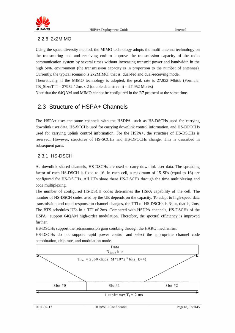
As downlink shared channels, HS-DSCHs are used to carry downlink user data. The spreading factor of each HS-DSCH is fixed to 16. In each cell, a maximum of 15 SFs (equal to 16) are configured for HS-DSCHs. All UEs share these HS-DSCHs through the time multiplexing and code multiplexing. The number of configured HS-DSCH codes determines the HSPA capability of the cell. The number of HS-DSCH codes used by the UE depends on the capacity. To adapt to high-speed data transmission and rapid response to channel changes, the TTI of HS-DSCHs is 3slot, that is, 2ms. The BTS schedules UEs in a TTI of 2ms. Compared with HSDPA channels, HS-DSCHs of the HSPA+ support 64QAM high-order modulation. Therefore, the spectral efficiency is improved further. HS-DSCHs support the retransmission gain combing through the HARQ mechanism. HS-DSCHs do not support rapid power control and select the appropriate channel code combination, chip rate, and modulation mode.
Slot #0 Slot#1 Slot #2
T slot = 2560 chips, M *10*2 k bits (k=4)
Data N data 1 bits
1 subframe: T f = 2 ms

HSPA+ Deployment Guide Internal
2011-07-17 HUAWEI Confidential Page19, Total45
Figure 2 Structure of an HS PDSCH frame
2.3.2 HS-SCCH
HS-SCCHs are downlink shared channels. Each HS-SCCH carries the information required for the UE to demodulate the HS-PDSCH, including UE ID, HS-DSCH code allocation information, modulation mode, and transport block size. Through the information, the UE determines whether the data on HS-DSCHs are sent to the UE and how to receive the data. The information carried by HS-SCCHs is important for the UE to demodulate the HS-DSCHs. HS-SCCHs transmit information two slots in advance than the corresponding HS-DSCHs. Therefore, the UE decides whether to demodulate HS-DSCHs after demodulating HS-SCCHs. The spreading factor of each HS-SCCH is 128. In a 2-ms TTI, the information carried on each HS-SCCH can only be used for one UE. Therefore, multiple HS-SCCHs must be configured if you schedule multiple UEs within 2 ms. A UE monitors a maximum of four HS-SCCHs at the same time.
Slot #0 Slot#1 Slot #2
T slot = 2560 chips, 40 bits
Data N data 1 bits
1 subframe: T f = 2 ms
Figure 3 Structure of an HS-SCCH frame
2.3.3 HS-DPCCH
HS-DPCCHs are uplink dedicated hannels. The spreading factor is 256. An uplink HS-DPCCH must be established for an HSPA-enabled UE. The uplink HS-DPCCH and other uplink channels of the UE adopt the code multiplexing mode. For non-MIMO users, information carried on HS-DPCCHs includes the ACK/NACK message used for the rapid retransmission in the physical layer and the CQI (channel quality result) measured by the UE. The BTS determines whether to transmit downlink data through the information.

HSPA+ Deployment Guide Internal
2011-07-17 HUAWEI Confidential Page20, Total45
S u b f ra m e # 0 S u b fra m e # i S u b f ra m e # 4
H A R Q - A C K C Q I
O n e ra d i o f ra m e T f = 1 0 m s
O n e H S -D P C C H s u b f ra m e (2 m s )
2 × T s lo t = 5 1 2 0 c h ip s T s lo t = 2 5 6 0 c h i p s
Figure 4 Structure of a non-MIMO HS-DPCCH frame
For MIMO users, the PCI information is added in the HS-DPCCH frame. Figure 5 shows that the PCI is added behind the CQI.
Subframe #0 Subframe # i Subframe #4
HARQ-ACK CQI/PCI
One radio frame T f = 10 ms
One HS-DPCCH subframe (2 ms)
2 × T slot = 5120 chips T slot = 2560 chips
Figure 5 Structure of a MIMO HS-DPCCH frame
2.4 Data Transmission on Physical Layer of HSPA+
This section describes data transmission on the physical layer of the HSPA+. Then, you can understand the role of each channel during the data transmission. If the setup of an HSPA+-enabled cell is supported, the BTS establishes downlink channels in terms of the number of HS-DSCH codes and the number of HS-SCCH codes. After an HSPA service is established, the UE continually measures the signal quality in the radio environment, calculates the CQI according to the pilot of the cell and the Measure Power Offset (MPO) configured for the UE by the BTS, and reports the CQI to the BTS through uplink HS-DPCCHs. The UE continually monitors the downlink HS-SCCHs to check whether the data is sent to the UE. After receiving the CQI, the BTS determines whether to send the data to the UE according to the CQI, PCI (only for MIMO users), BTS resource utilization, and UE capability. If yes, the BTS transmits the data block information, including the data block size, codes to be used, modulation

HSPA+ Deployment Guide Internal
2011-07-17 HUAWEI Confidential Page21, Total45
mode, and UE ID through HS-SCCHs. After two timeslots, the BTS transmits the data blocks of the UE on HS-DSCHs. If the UE finds that the data block information on HS-SCCHs is transmitted to the UE, the UE demodulates the HS-DSCHs by using the obtained information after two timeslots to obtain the data block information. In step 2, the CQI reporting period is set by the BTS to 2 ms, 4 ms, 8 ms, or 16 ms. Steps 3–5 are performed every 2 ms.
2.5 MAC-ehs Entity
Figure 6 MAC-ehs entity
After the Layer 2 Enhancement is introduced, MAC-ehs entities are added in the MAC layer of the Node B. Each cell has only one MAC-ehs entity.
If the UE supports the Layer 2 Enhancement technology during the HSDPA downlink data transmission, you can configure MAC-ehs or MAC-hs entities to process data transmitted on HS-DSCHs. The Layer 2 Enhancement technology is the basis of the 64QAM, MIMO, and Cell FACH. The RNC determines whether to configure the UE to use MAC-ehs entities according to the capability of the cell and UE. The great difference between the MAC-ehs and the MAC-hs is that the MAC-hs supports data segmentation and concatenation, supports multiple prior queues (a maximum of three), reorders and multiplexes SDUs (a maximum of 26) to MAC-ehs PDUs (2x2MIMO, that is, two MAC-ehs PDUs are transmitted during a TTI).

HSPA+ Deployment Guide Internal
2011-07-17 HUAWEI Confidential Page22, Total45
2.6 HSPA+ Signaling Plane and User Plane
2.6.1 HSPA+ Signaling Plane
With the introduction of the 64QAM and MIMO, certain information elements are added and related signaling procedures are affected. The following signaling procedures are for reference only. If the Node B supports the 64QAM or MIMO, the support capability must be notified to the 64QAM-enabled UEs...
1. Resource audit procedure
CRNC Node B
AUDIT REQUEST
AUDIT RESPONSE
Figure 7 Resource audit procedure
If a local cell supports the 64QAM or MIMO, the AUDIT RESPONSE from the Node B to the RNC must include the indication that the 64QAM or MIMO is supported.
2. Resource status indication
CRNC Node B
RESOURCE STATUS INDICATION
Figure 8 Resource status indication
If a local cell supports the 64QAM or MIMO, the RESOURCE STATUS INDICATION from the Node B to the RNC must include the indication that the 64QAM or MIMO is supported.

HSPA+ Deployment Guide Internal
2011-07-17 HUAWEI Confidential Page23, Total45
2.6.2 Data Transmission on HSPA User Plane
1. HS-DSCH data frame
Figure 9 Type 2 HS-DSCH data frame
The Layer 2 Enhancement technology is introduced in the HSPA+. Therefore, the type-2 data frame is added as shown in the preceding figure. The type-2 data frame supports the variable PDU size, and the frame header indicates the length of different data blocks.

HSPA+ Deployment Guide Internal
2011-07-17 HUAWEI Confidential Page24, Total45
2. Control frame on user plane
N o d e B C R N C
C A P A C IT Y R E Q U E S T
Figure 10 Capacity request frame
Capacity allocation: The Node B sends the CAPACITY ALLOCATION message to the RNC to notify the amount of data transmitted by the RNC in a certain period of time.
N o d e B C R N C
C A P A C IT Y A L L O C A T IO N
Figure 11 Capacity allocation frame
After the Layer 2 Enhancement technology is introduced, the capacity allocation frames can be classified into type 1 data frames and type 2 data frames. For HSDPA users supporting the Layer 2 Enhancement technology, type 1 data frames are adopted. Otherwise, type 2 data frames are adopted.
2.7 Mobility Management
2.7.1 HSPA+ Intra-Frequency Handover Policy
From the perspective of mobility, the HSPA+ is the same as R5 HSDPA, that is, the mobility control is based on changes of the serving cell, and the serving cell changes through the 1x events. To achieve high-quality data transmission on HS-DSCHs, the RNC is required to map the RAB to the HS-DSCHs of the best serving cell. Generally, the 1D measurement event (change of the best serving cell) is used to trigger the changes of the HS-DSCH serving cell to.
The introduction of the HSPA+ brings the following impacts on mobility:
Add intra-frequency handover between 64QAM cells or MIMO cells.
Add the handover between 64QAM cells and HSDPA/R99 cells or between MIMO cells and HSDPA/R99 cells due to changes of the cell capability.

HSPA+ Deployment Guide Internal
2011-07-17 HUAWEI Confidential Page25, Total45
UEs in the CELL_DCH state can use technologies such as 64QAM, MIMO, Layer 2 Enhancement. The prerequisite is that the corresponding cell implements the HSPA+ feature.
2.7.2 HSPA+ Inter-Frequency Handover Policy
The inter-frequency handover policies of the HSPA+ are the same as those of the HSDPA. The hard handover can be performed when the serving cell is being upgraded. Intra-Node B hard handover adopts the same signaling procedure with the inter-Node B hard handover. In this procedure, radio links and HS-DSCHs are set up in the new cell, physical channels are reconfigured, and old links are removed.
2.7.3 HSPA+ Inter-System Handover Policy
3G->2G handover The 3G-to-2G handover process of an HSPA+-enabled UE is the same as that of an HSDPA-enabled UE. If the HSPA+-enabled UE is set to disable the compression mode through the SET CMCF command, services are carried on DCHs (the compression mode is enabled). Then, the UE switches to the 2G network. When services of the HSPA+-UE are carried on DCHs, the H2D process is started. The Uu interface and the Iub interface complete the RB reconfiguration and the RL reconfiguration respectively to run the service on DCHs instead of HS-DSCHs. 2G->3G handover The 2G-to-3G handover process of the HSPA+ is the same as that of the HSDPA. If HS-DSCHs can carry the RAB with requested rate, the RB is set up on HS-DSCHs.
Chapter 3 Upgrade Guide
3.1 RNC Upgrade
3.1.1 Upgrade Requirement
The following table lists the recommended RNC versions for commercial use.
Table 5 Recommended RNC version
Recommended RNC Version Whether to Support HSPA+ 64QAM&MIMO
BSC6800V100R011C00SPC120 or later version
Yes
BSC6810V200R011C00SPC120 Yes
HSPA+ Deployment Guide Internal
2011-07-17 HUAWEI Confidential Page26, Total45
or later version
To support the HSPA+ commercialization, the RNC hardware configuration does not impose special requirement on the BSC6810. For the BSC6800, at least the FMRc is configured to support the HSPA+. Unless otherwise stated, the following upgrade steps are applicable to RAN11.0 V1 and V2.
3.2 NodeB Upgrade
1. Before upgrading, please confirm the hardware of NodeB support HSPA+ commercialization, the content refers to Chapter 1.2.1
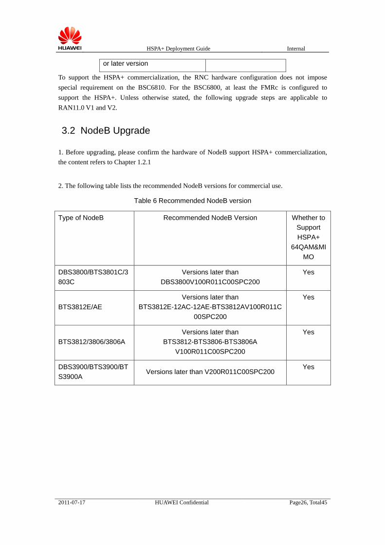
2. The following table lists the recommended NodeB versions for commercial use.
Table 6 Recommended NodeB version
Type of NodeB Recommended NodeB Version Whether to Support HSPA+
64QAM&MIMO
DBS3800/BTS3801C/3803C
Versions later than DBS3800V100R011C00SPC200
Yes
BTS3812E/AE Versions later than
BTS3812E-12AC-12AE-BTS3812AV100R011C00SPC200
Yes
BTS3812/3806/3806A Versions later than
BTS3812-BTS3806-BTS3806A V100R011C00SPC200
Yes
DBS3900/BTS3900/BTS3900A
Versions later than V200R011C00SPC200 Yes

HSPA+ Deployment Guide Internal
2011-07-17 HUAWEI Confidential Page27, Total45
Chapter 4 Data Configuration Policy
4.1 HSPA+ Network Establishment
4.1.1 GGSN Configuration (Huawei)
The HSPA+ provides a higher throughput than the HSDPA. That is, the UMTS supports a higher rate. In addition, capacity-related attributes must be set on the GGSN. Run the following command to set the maximum rate to 256000 kbit/s.
SET QOS: MBRDNLK=256000, GBRDNLK=256000; (1) On the GGSN, run the commands LST QoS and SET QoS to check whether the uplink and downlink data rate reaches the required value. If not, modify the uplink and downlink data rate. (2) On the GGSN, run the LST APNQoS command to check whether the uplink data rate of a certain APN is set. If not, do not set or ignore the rate. If yes, check whether the rate reaches the required value. If not, set the rate value.
4.1.2 SGSN Configuration (Huawei)
The method of configuring the SGSN is similar to that configuring the GGSN. Set the Extended MBR to 250 (MBRDNLKEX 250 represents 256 Mbit/s).
SET 3GSM: PARATYPE=QOS, MBRUPLK=254, GBRUPLK=254, MBRDNLK=254, GBRDNLK=254, MBRDNLKEX=250, GBRDNLKEX=250, MBRUPLKEX=250, GBRUPLKEX=250;
SET PROCR: RNCQOSVERSION=R7, GGSNQOSVERSION=R7, SGSNQOSVERSION=R7; Set the RNC version to R7. Note that the following command corresponds to the index of the RNC actually used.
MOD RNC: IMS=YES, RNCVER=R7, R7QOS=YES; Set the QoS attribute of a certain GGSN to R7Qos.
MOD GGSNCHARACT: IPT=IPV4, QOSVER=R7Qos; On the SGSN, run the commands LST COMPATIBILITY and SET COMPATIBILITY to set RABQOS to YES.
SET COMPATIBILITY: RABQOS=YES;
4.1.3 Registration Rate Configuration
According to the rate requirement of the operator, set the downlink data rate. If the HSPA+ feature is supported, the rate is expanded to 21 Mbit/s (if the 64QAM is supported) or 28 Mbit/s (if the MIMO is supported).

HSPA+ Deployment Guide Internal
2011-07-17 HUAWEI Confidential Page28, Total45
4.2 Check on Transmission Configuration on Iub or Iu
Interface
4.2.1 Check on Transmission Configuration on Iub Interface
Add the types of paths that transmit the HSPA service on the RNC and NodeB sides. The HSPA+ improves the transmission requirement of the Iub interface. Therefore, it is recommended to adopt IP networking on the Iub interface. For the bandwidth configuration of the IP RAN, refer to the HSPA+ bandwidth configuration of the IP RAN deployment guide. You can check the bandwidth in the ATM network by using the following method:
ADD AAL2PATH: AAL2PATHT=HSPA;
On the RNC, run the DSP AAL2 PATH command to check the available bandwidth of the AAL2 path carrying the HSPA. If the HSPA+ is supported, set the bandwidth to the maximum value. On the Node B, the size of HSPA+ bandwidth depends on the Receive Cell Rate (RCR). Check the RCR of the AAL2 path. It is recommended that the RCR is set to a maximum of 20 Mbit/s to impose strict requirement on the HSPA+ bandwidth. However, for a single user, this rate cannot meet the peak value requirement (this cannot meet the peak rate requirement of a single UE).
4.2.2 Check on Bandwidth of Iu-PS Interface
(1) Run the LST IPOA command to check the traffic index of the user plane. (2) Run the LST TRAFFIC command to check the bandwidth corresponding to the traffic index. You also can obtain the supported rate, PCR peak cell rate (cells/s), and cell rate (cells/s) corresponding to the traffic index. If the supported rated is too low, you can modify it manually. 1000 bit/s is recommended.
4.2.3 Node B Configuration
The 64QAM-enabled or MIMO-enabled cell must be set up on the enhanced board. Otherwise, the HSPA+ feature is not supported. After the cell is set up, check whether the downlink resource group is established on the enhanced board, that is, run the DSP LOCELLRES command to check whether the downlink resource group established on the enhanced board or not. For the BTS3812E, the number of the slot that controls the downlink resource group is the number of that houses the EBBI, EULP, or EDLP. For the DBS3800, the number of the slot that controls the downlink resource group is the number of that houses the EBBC. For the DBS3900, the number of the slot that controls the downlink resource group is the number of that houses the WBBPb.
For the BTS3801C/3803C, it supports the HSPA+ with EBBM board added.
The configuration of a local 64QAM cell is the same as that of an HSDPA-enabled cell. For an MIMO-enabled cell, however, you must configure the NodeB and the cell must supports the

HSPA+ Deployment Guide Internal
2011-07-17 HUAWEI Confidential Page29, Total45
transmit diversity mode. In addition, the local cell can be configured in serial connection mode or parallel connection mode. The former is recommended. 4.2.3.1 Node B Configuration of MIMO-Enabled Cell in Parallel Connection Mode
1. Run the following command to add two RRUCHAINs:
ADD RRUCHAIN: RCN=0, TT=CHAIN, HSN=0, HPN=0;
ADD RRUCHAIN: RCN=1, TT=CHAIN, HSN=0, HPN=1;
2. Run the following command to add two RRUs:
ADD RRU: SRN=20, TP=TRUNK, RCN=0, PS=0, RT=MRRU;
ADD RRU: SRN=21, TP=TRUNK, RCN=1, PS=0, RT=MRRU;
3. Run the following command to add a SEC and select the common mode:
ADD SEC: STN=0, SECN=0, SECT=REMOTE_SECTOR, ANTM=2, DIVM=COMMON_MODE;
4. Run the following command to add a local cell, set the dual-fed capability to True, and configure two power amplifiers.
ADD LOCELL: LOCELL=0, STN=0, SECN=0, SECT=REMOTE_SECTOR, TTW=TRUE, SRN1=20, SRN2=21, HISPM=FALSE, RMTCM=FALSE;
4.2.3.2 Node B Configuration of MIMO-Enabled Cell in Serial Connection Mode The configuration of the RRU cell in serial connection mode is the same as that in parallel connection mode. The only difference is that only one RRUCHINA is required in serial connection mode.
1. Run the following command to add an RRUCHAIN:
ADD RRUCHAIN: RCN=0, TT=CHAIN, HSN=0, HPN=0;
2. Run the following command to add two RRUs on an identical RRUCHAIN:
ADD RRU: SRN=20, TP=TRUNK, RCN=0, PS=0, RT=MRRU;
(Position 0)
ADD RRU: SRN=21, TP=TRUNK, RCN=0, PS=1, RT=MRRU;
(Position 1)
3. Run the following command to add a SEC and configure the Tx diversity.
ADD SEC: STN=0, SECN=0, SECT=REMOTE_SECTOR, ANTM=2, DIVM=COMMON_MODE;
4. Run the following command to add a local cell, set the dual-fed capability to True, and configure two power amplifiers.
ADD LOCELL: LOCELL=0, STN=0, SECN=0, SECT=REMOTE_SECTOR, TTW=TRUE, SRN1=20, SRN2=21, HISPM=FALSE, RMTCM=FALSE;
4.2.4 RNC Configuration
1. Hardware check: For the BSC6800, the RNC requires to use the FMRc board to support the HSPA+ feature; for the BSC6810 platform, there is no hardware limits.
2. Run the following command to enable the HSDPA feature to configure attributes of the 64QAM and the MIMO.
SET CORRMALGOSWITCH:CfgSwitch= CFG_HSDPA_64QAM_SWITCH-1&CFG_HSDPA_MIMO_SWITCH-1;

HSPA+ Deployment Guide Internal
2011-07-17 HUAWEI Confidential Page30, Total45
3. Run the following command to turn on the switch of the 64QAM, MIMO, and Layer 2 Enhancement in the algorithm.
MOD CELLALGOSWITCH: HspaPlusSwitch=64QAM-1&MIMO-1&L2ENHANCED-1;
4. The license supports the enabling of the switch of 21 Mbit/s and 28 Mbit/s (You can run the DSP LICENSE command to check the switch configuration).
5. Run the following command to activate the corresponding HSPA+ cell:
ACT CELLHSDPA: CellId=0;
6. For the MIMO-enabled cell, run the ADD QUICKCELLSETUP command to set up a local cell and run the MOD CELLSETUP command to configure the transmit diversity and STTD attributes.
MOD CELLSETUP: CellId=0, TxDiversityInd=TRUE, STTDSupInd=STTD_Supported, CP1SupInd=CP1_not Supported, DpchPrioTxDiversityMode=STTD, HspdschPrioTxDiversityMode=STTD, DpchDivModforMIMO=STTD;
7. For the MIMO-enabled cell, run the following command to activate the MIMO feature:
ACT CELLMIMO;
4.3 Service and Bearer Configuration
4.3.1 HSPA+ Configuration During Registration
All registration-related information is configured on the HLR. HSPA+-related parameters are described previously and determined by operators according to requirements.
4.3.2 Code Allocation of HSPA+-Enabled Cell
The code allocation is based on the cell. Fixed code allocation and RNC-based dynamic code allocation are configured on the RNC. Node B-based dynamic code allocation is configured on the Node B. The code allocation configured on the RNC and that on the Node B do not affect each. That is, you can enable the Node B-based dynamic code allocation when configuring the fixed code allocation on the RNC, or disable the Node B-based dynamic code allocation when configuring the dynamic code allocation on the RNC. It is recommended to enable the Node B-based dynamic code allocation. Thus RNC using fixed code allocation. Run the ADD CELLHSDPA command to configure code allocation in the RNC, for example, configure the static code allocation policy and allocate two HS-SCCH codes.
ADD CELLHSDPA: AllocCodeMode=Manual, HsPdschCodeNum=1, HsScchCodeNum=2, CodeAdjForHsdpaSwitch=ON;
If the Node B-based dynamic code allocation is closed. Run the following command to configure RNC-based dynamic code allocation policy, set the maximum number of HS-PDSCH codes to 15, the minimum number HS-PDSCH codes to 1, and the number of HS-SCCH codes to 2.
ADD CELLHSPA: CellId=1, AllocCodeMode=Automatic, HsPdschMaxCodeNum=15, HsPdschMinCodeNum=1, HsScchCodeNum=2;
To enable the Node B-based dynamic code allocation policy, run the SET MACHSPARA

HSPA+ Deployment Guide Internal
2011-07-17 HUAWEI Confidential Page31, Total45
command as follows: SET MACHSPARA: LOCELL=1, DYNCODESW=OPEN;
The dynamic code allocation policy adopted on the Node B is not detected on the LMT of the RNC. If idle codes (SF=16) are available, these codes are allocated to the HSPA.
4.3.3 Power Configuration of HSPA+-Enabled Cell
Run the ADD CELLHSDPA command to configure the power of the HSPA+-enabled cell in the RNC by using.
ADD CELLHSDPA: AllocCodeMode=Automatic, HspaPower=0;
The configured power is the power offset of the maximum transmit power of the HSPA+-enable cell.
4.3.4 HSPA+ Scheduling and Flow Control Configuration
The scheduling algorithm is configured on the Node B by using the SET MACHSPARA command, for example, you can run the following command to adopt the EPF scheduling algorithm on the Node B:
SET MACHSPARA: SM=EPF
It is recommended to adopt default settings of flow control parameters. For the flow control policy, DYNAMIC_BW_SHAPING or NO_BW_SHAPING can be selected automatically through the congestion check mechanism. You can also run the following command to configure the flow control policy:
SET HSDPAFLOWCTRLPARA: SWITCH=BW_SHAPING_ONOFF_TOGGLE;
4.3.5 HSPA+ Power Control Configuration
The power control of HS-DPCCHs is configured on the RNC by using the SET HSDPCCH command. It is recommended to adopt baseline parameters. The power control of HS-SCCHs is configured on the Node B by using the SET MACHSPARA command, for example, to adjust the HS-SCCH the power control based on the CQI, set the offset relative to the initial power of the PCPICH to 0dB, and set the frame error rate to 1%, run the following command:
SET MACHSPARA: SCCHPWRCM=CQI, SCCHFER=10;
To set the power margin of the cell to 5% of the baseline value, run the following command: SET MACHSPARA: PWRMGN=5;
4.3.6 QoS Guarantee Configuration of HSPA+
Run the SET USERPRIORITY command to map the ARP to the SPI. The following command set the UE level of each ARP priority.
SET USERPRIORITY: ARP1Priority=Gold, ARP2Priority=Gold, ARP3Priority=Gold, ARP4Priority=Gold, ARP5Priority=Gold, ARP6Priority=Silver, ARP7Priority=Silver,

HSPA+ Deployment Guide Internal
2011-07-17 HUAWEI Confidential Page32, Total45
ARP8Priority=Silver, ARP9Priority=Silver, ARP10Priority=Silver, ARP11Priority=Copper, ARP12Priority=Copper, ARP13Priority=Copper, ARP14Priority=Copper;
Run the SET SCHEDULEPRIOMAP command to map the UE service type and class to the SPI. SET SCHEDULEPRIOMAP: TrafficClass=INTERACTIVE, UserPriority=SILVER, THP=10, SPI=5;
Run the SET USERGBR command to configure the GBR for BE services. SET USERGBR: GoldUlGBR=D128, GoldDlGBR=D128, SilverUlGBR=D64, SilverDlGBR=D64, CopperUlGBR=D32, CopperDlGBR=D32;
In the preceding example, the GBR parameters use the baseline values. The values can be changed according to the operator requirements.
4.3.7 License Configuration for HSPA+
Apply for licenses of the RNC to support the traffic of 21 Mbit/s and 28 Mbit/s.
******************************************************************************* Note
You can query settings of the preceding parameters first. If these parameters are set to baseline values, the
modification is unnecessary.
*******************************************************************************Radio Resource Management Configuration
4.3.8 HSPA+ Measurement Control Configuration
Generally, the following parameters are set to baseline values; therefore, you do not need to modify parameter settings. Configuration related to HSPA+ measurement includes configuration of the measurement switch and measurement period. Run the MOD CELLALGOSWITCH command to configure the measurement switch. To measure the GBP and PBR, run the following command.
MOD CELLALGOSWITCH: CellId=1, NBMCacAlgoSwitch=HSPA_GBP_MEAS-1&HSPA_PBR_MEAS-1;
Run the SET LDM command to set the measurement period. To set the basic downlink measurement period to 200 ms, run the following command:
SET LDM: ChoiceRprtUnitForDlBasicMeas=TEN_MSEC, TenMsecForDlBasicMeas=20;
To set the HSPA GBP measurement period and HSPA PBR measurement period to 1 second, run the following command:
SET LDM: ChoiceRprtUnitForHSPAPwrMeas=TEN_MSEC, TenMsecForHSPAPwrMeas=100;
SET LDM: ChoiceRprtUnitForHSPARateMeas=TEN_MSEC, TenMsecForHSPAPrvidRateMeas=100;
4.3.9 HSPA+ Admission Control Configuration
During deployment, use the baseline values of the following parameters. You do not need to change the values of these parameters.

HSPA+ Deployment Guide Internal
2011-07-17 HUAWEI Confidential Page33, Total45
Similar to that of the HSDPA, run the following command to turn on the admission control switch of the HSPA+:
ADD CELLALGOSWITCH: NBMCacAlgoSwitch=HSPA_ADCTRL-1;
Run the following commands to turn on the Iub bandwidth admission switch. SET CACALGOSWITCH: CacSwitch=IUB_CONG_CAC_SWITCH-1;
ADD CELLALGOSWITCH: NBMCacAlgoSwitch=IUBBAND_ADCTRL-1;
Run the following commands to turn on the CE resource admission control switch. SET CACALGOSWITCH: CacSwitch=NODEB_CREDIT_CAC_SWITCH-1;
ADD CELLALGOSWITCH: NBMCacAlgoSwitch=CRD_ADCTRL-1;
4.3.10 HSPA+ DRD Configuration
The DRD policy of the HSPA+ is the same as that of the HSDPA. The following parameters are set when the dual carrier is adopted during the deployment. To support the DRD of the HSPA+, turn on the HSPA DRD algorithm switch and the blink handover switch when the inter-frequency concentric neighboring cell is configured. To turn on the two switches, run the following commands:
SET CORRMALGOSWITCH:DrSwitch=DR_RRC_DRD_SWITCH-1;;
ADD INTERFREQNCELL:BlindHoFlag=TRUE, BlindHOPrio=0;
4.3.11 HSPA+ Load Control Configuration
During deployment, use the baseline values of the following parameters. You do not need to change the values of these parameters. When congestion occurs to a cell, the system can take multiple measures to relieve the congestion of the cell. However, few actions are related to the HSPA service. The following commands are related to the HSPA service. Run the SET CORRMALGOSWITCH command to turn on the HSPA state transition switch, intra-frequency D2H algorithm switch, and inter-frequency D2H algorithm switch.
SET CORRMALGOSWITCH: DraSwitch=DRA_HSDPA_STATE_TRANS_SWITCH-1&DRA_HSUPA_STATE_TRANS_SWITCH-1, DrSwitch=DR_RRC_DRD_SWITCH-1;
Run the ADD CELLALGOSWITCH command to turn on the load reshuffling algorithm switch, code resource reshuffling algorithm switch, and CE resource reshuffling algorithm switch.
ADD CELLALGOSWITCH: CellId=1, NBMLdcAlgoSwitch=ULLDR-1&DLLDR-1&CELL_CODE_LDR-1&CELL_CREDIT_LDR-1;
Run the ADD CELLLDR command to control load reshuffling algorithm parameters. In addition, the traffic type of the cell can be determined by traffic distribution.
ADD CELLINETSTRATEGY: R99CSSepInd=TRUE, R99PSSepInd=TRUE;
4.4 Typical HSPA+ Configuration in Competition Scenarios
If the uplink adopts R99 connections, you can adopt the fixed SIR Target in the case of high BER

HSPA+ Deployment Guide Internal
2011-07-17 HUAWEI Confidential Page34, Total45
and set the initial value, maximum value, and minimum value to 172 (9dB) through the following method:
1. Run the EXP INNERCFGMML command on the LMT to export internal scripts. 2. Search exported scripts for the index of the registered traffic corresponding to the uplink
384-kbit/s traffic, for example the traffic class is INTERACTIVE, and RABINDEX is 48. ADD TYPRABBASIC:RABINDEX=48, APPLIEDDIRECT=APPLIED_ON_BOTH, CNDOMAINID=PS_DOMAIN, TRAFFICCLASS=INTERACTIVE, MAXBITRATE=384000, SSD=UNKNOWN, TYPCFGSUPPORT=ON, BETAC=4, BETAD=15, SHIND=HO_TO_GSM_SHOULD_NOT_BE_PERFORM, REQ2GCAP=EDGE, ULFPMODE=SILENT;
3. Search scripts for corresponding outer loop power control parameter OLPC if the RABINDEX is 48.
ADD TYPRABOLPC:RABINDEX=48, SUBFLOWINDEX=0, TRCHTYPE=TRCH_DCH, DELAYCLASS=1, BLERQUALITY=-20, BLERTARMAPIND=FALSE, SDUERRRATIOUPMANTISSA=9, SDUERRRATIOUPEXP=3, SDUERRRATIOLOWMANTISSA=1, SDUERRRATIOLOWEXP=6, MAXSIRSTEPUP=1000, MAXSIRSTEPDN=500, SIRADJUSTSTEP=4, INITSIRTARGET=152, MAXSIRTARGET=172, MINSIRTARGET=152, SIRADJUSTPERIOD=2, TYPICALBERDPCCH=300, BERTARGET1=0, BERTARGET2=0, SIRSTEPUPONBER=0, SIRSTEPDOWNONBER=0, DTXBERTARFILTERCOEF=0, NONDTXBERTARFILTERCOEF=800;
4. Run the following command to modify the initial value, maximum value, and minimum value (obtained from the output of the preceding command) to 172 (9dB).
MOD TYPRABOLPC:RABINDEX=48, SUBFLOWINDEX=0, TRCHTYPE=TRCH_DCH, DELAYCLASS=1, BLERQUALITY=-20, BLERTARMAPIND=FALSE, SDUERRRATIOUPMANTISSA=9, SDUERRRATIOUPEXP=3, SDUERRRATIOLOWMANTISSA=1, SDUERRRATIOLOWEXP=6, MAXSIRSTEPUP=1000, MAXSIRSTEPDN=500, SIRADJUSTSTEP=4, INITSIRTARGET=172, MAXSIRTARGET=172, MINSIRTARGET=172, SIRADJUSTPERIOD=2, TYPICALBERDPCCH=300, BERTARGET1=0, BERTARGET2=0, SIRSTEPUPONBER=0, SIRSTEPDOWNONBER=0, DTXBERTARFILTERCOEF=0, NONDTXBERTARFILTERCOEF=800;
5. Copy the preceding command to the blank area of the MML command to run this command.
6. Check whether the SIR Target switch for the radio link reconfiguration is enabled. If not, enable this parameter to notify modifications of parameter settings to the Node B.
s
7. After the demonstration, run the following command to change parameters to initial values. Otherwise, performance of multiple UEs in the existing network is affected (copy the following command to the blank area of the MML command and run this command).
MOD TYPRABOLPC:RABINDEX=48, SUBFLOWINDEX=0, TRCHTYPE=TRCH_DCH, DELAYCLASS=1, BLERQUALITY=-20, BLERTARMAPIND=FALSE, SDUERRRATIOUPMANTISSA=9, SDUERRRATIOUPEXP=3, SDUERRRATIOLOWMANTISSA=1, SDUERRRATIOLOWEXP=6, MAXSIRSTEPUP=1000, MAXSIRSTEPDN=500, SIRADJUSTSTEP=4, INITSIRTARGET=152, MAXSIRTARGET=172, MINSIRTARGET=152, SIRADJUSTPERIOD=2, TYPICALBERDPCCH=300, BERTARGET1=0, BERTARGET2=0, SIRSTEPUPONBER=0, SIRSTEPDOWNONBER=0, DTXBERTARFILTERCOEF=0, NONDTXBERTARFILTERCOEF=800;
HSPA+ Deployment Guide Internal
2011-07-17 HUAWEI Confidential Page35, Total45
Chapter 5 Networking Policy
5.1 Overview
With the rapid development of the HSPA+, it is an inevitable trend to introduce the HSPA+ to
commercial networks. The MIMO requires the STTD to set to ON. Therefore, the performance of
certain HSDPA terminals of R5 and R6 deteriorates due to the rollback of the receiver type.
Generally, it is recommended that a MIMO cell shares carriers with an R99 cell instead of an
HSDPA cell. The network policies of the 64QAM are the same as those of the HSDPA. A
64QAM-enabled cell can share the second carrier with an HSDPA-enabled cell. The networkings
of the 64QAM and MIMO are configured separately.
Considering actual operation scenarios and industry policies, the prerequisite to introduce the
HSPA+ is that the existing HSDPA or R99 services are not affected. That is, compared with the
HSDPA and HSPA+ services, the R99 service
1. The R99, HSDPA, and HSPA+ services can share power resources dynamically. However,
the R99 service is always preferred.
2. The R99, HSDPA, and HSPA+ services can share code resources dynamically. However,
the R99 service is always preferred.
3. The R99, HSDPA, and HSPA+ services fully share transmission resources. However, the
R99 service is always preferred.
To guarantee the smooth operation of the HSPA+ service, Configure a GBR for the HSPA+
service to ensure the minimum power, code, and transmission resources obtained by the service.
For the HSPA+-enabled dual-carrier service, the research focuses on how to allocate code, power,
and transmission resources to the HSPA+ and R99 service to achieve the maximum resource usage
in addition to the original features of the R99 service.

HSPA+ Deployment Guide Internal
2011-07-17 HUAWEI Confidential Page36, Total45
5.2 HSPA+ 64QAM Dual-Carrier Service Allocation Policy
5.2.1 HSPA+ 64QAM Networking Mode I
The first carrier supports the R99 and HSPA services (including the HSDPA service and
HSPA+64QAM service) and implements continuous coverage. The second carrier supports the
HSDPA service and HSPA+ 64QAM service. The following figure shows the networking.
Figure 12 Dual-carrier networking I
The networking advantage is that either the networking policy or the configuration is simple, and
the uniform management is implemented in the network. One clear disadvantage is that the HSPA
fails to achieve load balancing. The R99 service can preempt either code or power resources of the
HSDPA service. Therefore, it is difficult to guarantee smooth operation of the HSDPA and HSPA+
64QAM services and trigger the load balancing between the two carriers. In addition, the load
balancing of the HSPA service brings fluctuations and the ping-pong effect.
5.2.2 HSPA+ 64QAM Networking Mode II
The first TRX implements continuous coverage and the second TRX covers hot spot areas. Both
the two TRXs support the R99 and HSPA+ 64 QAM.
R99+H R99+H R99+H
R99+H R99+H R99+H R99+H R99+H F1
F2
Hot Spot Hot Spot
1 2
1
R99+H R99+H R99+H
R99+H
R99 R99 R99 R99+H F1
F2
Hot Spot Hot Spot
1 2
1

HSPA+ Deployment Guide Internal
2011-07-17 HUAWEI Confidential Page37, Total45
Figure 13 Dual-carrier networking II
Networking mode II greatly differs from networking mode I in camping policies, mobility
management, and load control.
The advantage of networking mode II is to guarantee smooth operation of the R99 and HSPA+
64QAM services and ensure load balancing of the HSDPA service. The disadvantage is that the
networking is complex and involves multiple policies and configurations.
5.2.3 Comparison of Two HSPA+ 64QAM Networking Modes
Table 6 shows advantages and disadvantages of the two networking modes.
Table 7 Comparison of two networking modes
Scenario Name Advantage Disadvantage
Dual carrier scenario I: Both
two carriers provide continuous
coverage of the HSPA service.
1. The two carriers implement continuous
coverage of the HSPA service.
2. Both R99 and HSPA users can make calls in this
cell, and the access delay is low. 3. R99 users
implement load sharing in hot spot areas. Therefore,
cells served by the two carriers achieve
load balancing. 4. HSPA users implement load
balancing through random camping
policies.
1. The network is expensive to construct. 2. HSPA users do not
achieve load balancing. 3. HSPA resources are configured preferentially for each TRX. Therefore,
it is hard to ensure the smooth operation of the
HSPA service.

HSPA+ Deployment Guide Internal
2011-07-17 HUAWEI Confidential Page38, Total45
Dual carrier scenario II: HSPA
cells are not covered
continuously (recommended).
1. The R99 service is covered
continuously by a single TRX. Users can obtain good
experience. 2. HSPA-enabled
UEs initiate PS calls in the cell covered
by frequency 2. Experience of HSPA
users is greatly improved because
there are fewer R99 users in the cell.
1. If the HSPA-enabled UE enters from the area
covered by the single TRX to that covered by double TRXs, the UE is
handed over to the intra-frequency R99 cell and cannot be handed
over to the inter-frequency HSPA
cell. Therefore, the HSPA coverage cannot
be implemented. 2. When initiating a call, the HSPA-enabled UE is
handed over to an inter-frequency cell
through the DRD. This can affect the access
delay of the UE.
To guarantee smooth operation of the HSPA service, commercial networks of Huawei adopt
networking mode II. Networking mode I involves simple policies, configuration, and algorithms
and is similar to common dual carrier networking.
5.3 Introduction to MIMO Networking Policy
If a MIMO-enabled cell shares one carrier with a common R5 or R6 cell, the type of the HSDPA
receiver rolls back and performance of HSDPA UEs deteriorates. Therefore, the MIMO
networking must be separate from the HSDPA networking. The general principle is as follows:
Maximize the MIMO capacity grain and balance powers of the two transmit channels.
Avoid performance loss of R5 HSPA UEs.
There are three MIMO networking modes.
5.3.1 MIMO Networking Mode I
The MIMO technology is deployed on a single frequency, which poses little impact on existing
networks. However, another frequency is required. Currently, most networks adopt dual carrier
networking, that is, at least operators provide three 3G frequencies.

HSPA+ Deployment Guide Internal
2011-07-17 HUAWEI Confidential Page39, Total45
Figure 14 MIMO networking mode I
Advantage
The MIMO technology is deployed separately from existing networks. This imposes minimum impacts on existing networks and does not affect the coverage, capacity, or KPIs.
Disadvantage
The MIMO technology requires to be deployed on an independent frequency and has extra requirements on frequency resources. In the early application period, the penetration ratio of MIMO-enabled UEs is low, and network resource usage is not high.
5.3.2 MIMO Networking Mode II
If frequency resources are limited, the MIMO deployment can be bound to the R99 service. This
avoids performance loss of old R5 HSPA UEs. The networking is as follows:
Figure 15 MIMO networking mode II
Advantage
Separate MIMO carrier from HSPA carriers. This avoids performance loss of original R5 HSPA UEs in the diversity cell. The MIMO service and R99 service are bound to an identical carrier to reduce the number of required frequencies. During the early period of the MIMO application, high-end users are fewer. Therefore, binding the

HSPA+ Deployment Guide Internal
2011-07-17 HUAWEI Confidential Page40, Total45
MIMO and R99 services to an identical carrier improves user experience and increases network resource usage.
Disadvantage
Binding the MIMO and R99 services to an identical carrier increases the average downlink load of frequency F1 and affects KPIs of the R99 cell because the HSPA service consumes larger downlink power. In this case, you can control uplink load to relieve these impacts.
5.3.3 MIMO Networking Mode III
If the operator increases the second TRX to deploy the HSPA+ during the Tx only networking, it is recommended to deploy the MIMO on a single TRX. This imposes little impact on the existing
network. The networking is as follows:
Figure 16 MIMO networking mode III
Advantage
The MIMO technology is deployed separately from existing networks. This imposes minimum impacts on existing networks and does not affect the coverage, capacity, or KPIs.
Disadvantage
The MIMO technology requires to be deployed on an independent frequency and has extra requirements on frequency resources. In the early period, the penetration ratio of MIMO-enabled UEs is low, and network resource usage is not high. If the HSPA performance loss is acceptable, you can enable the LDR switch to increase resource usage.
For the MIMO, networking mode II is recommended, that is, the R99 service shares one carrier with the MIMO service. If the frequency resource usage reaches the maximum value, the impacts on R5 HSDPA UE is minimized.

HSPA+ Deployment Guide Internal
2011-07-17 HUAWEI Confidential Page41, Total45
Chapter 6 FAQs
6.1 Services Failing to Access HSPA Channels
1. Check whether the UE supports the service. 2. Check whether the registered rate of the SIM card is correct. 3. Check whether the initial rate reaches the rate threshold of HSPA channels. 4. Run the DSP CELL command on the RNC to check whether the HSPA service of related cells is available.
6.2 Low Download Rate of HSPA Service
1. Check whether the UE supports high-rate download. 2. Check whether transmission bandwidth is limited. 3. Check whether the index of the traffic transmitted on paths of the RNC and Node B is correct. 4. Check whether the path configuration on the RNC is consistent with that on the Node B. If the RCR of the Node B is greater than the transmission bandwidth of the RNC, the transmission rate is lowered due to packet loss. Recommended relation is: Node B’s RCR=RNC’ s SCR, RNC’ s SCR=PCR-1 5. For the HSPA+ service, it is recommended to adopt IP networking and configure sufficient bandwidth to meet high rate requirement of the HSPA+ service.
6.3 Rate of High-rate HSPA+ Service (21 Mbit/s) Being Low
Tests on a site show that the rate of the high-rate HSPA+ download service (21 Mbit/s) is in low. Make clear that the download service is a single thread or multithread service. Factors that affect the single thread service are as follows:
Registered rate
Size of the TCP receiving window on the PC (the size can be modified by using the DRTCP tool)
Rate limit of the server
Packet loss on the TCP layer
Packet delivery in sequence or randomly (It is recommended that packets are delivered in sequence on the uplink)
Rate limit on the Iu interface (check whether the bandwidth of the Iu interface on the user plane is sufficient)
Iub flow control (it is recommended to maintain the flow control)
Bandwidth limit on the Iub interface (Check whether the bandwidth is sufficient)
HSPA+ Deployment Guide Internal
2011-07-17 HUAWEI Confidential Page42, Total45
BLER of the Uu interface (Check the quality of the tested radio environment. The peak rate of the HSPA+ service imposes high requirements on the quality of the Uu interface. Therefore, the radio environment of the Uu interface must be high-quality.)
Great impact imposed by the CQI on the single thread service (check the quality of the tested radio environment)
Problems occurred in the multithread service are different from those in the single thread service. The cause may be one of the followings:
Problems occurred on the Iub interface (see the preceding configuration specifications)
******************************************************************************* Note: For the IP networking environment, check settings of all ports to ensure that the CN and switch work in
forcible full duplex mode.
*******************************************************************************
Rate limit on the Iu interface
Poor-quality radio environment (Observing Ec/N0 on the LMT or by using other tools)
Packet loss on data sources of the CN causing insufficient data sources
The most possible cause is that the configuration of the portable computer and the driver of the UE cause low rate in the application layer. The recommended configuration of portable computers is as follows:
1GB memory
high-performance CPU
UE E270+ (driver of the latest version)
No packet loss in the CN
High rate
High performance in the application layer on the receiving side
In conclusion, the HSPA+ imposes high requirements on each NE, portable computers, and FTP server. Guarantee performance of the portable computers and the FTP server in actual tests. Otherwise, performance of the HSPA+ service may be affected.

HSPA+ Deployment Guide Internal
2011-07-17 HUAWEI Confidential Page43, Total45
Chapter 7 Appendix
7.1 RNC-Related MML Commands
MML Command Description Function
ADD NODEB Add a Node B. Set the protocol version on the Node B side.
ADD CELLHSPA Set HSPA parameters of
the cell. Configure basic resources of the HSPA feature.
ACT CELLHSPA Activate the HSPA
feature (high-speed
downlink packet access)
of the cell.
Activate the HSPA feature of the cell.
DEA CELLHSPA Deactivate the HSPA
feature (high-speed
downlink packet access)
of the cell.
Deactivate the HSPA feature of the cell.
ADD CELLCAC Set parameters related to
the admission control
algorithm of the cell.
Set parameters related to the HSPA admission control algorithm.
SET CORRMALGOSWITCH
Set the
connection-oriented
algorithm switch.
Set the HSPA algorithm switch.
SET FRC Set parameters relating
to the RNC-oriented
basic channel
configuration algorithm
(FRC).
Set basic channel algorithm parameters of the HSPA feature.
SET SCHEDULEPRIOMAP
Set mapping information about the scheduling priority.
Set scheduling priorities of the
HSPA feature.
ADD TYPRABBASIC/ MOD TYPRAB
Add/modify basic
parameters of the radio
bearer of the typical
service.
Add/Modify basic information about the typical service.
ADD TYPRABRLC/MOD TYPRABRLC
Add/Modify radio link
control parameters of the
radio bearer of a typical
Add/Modify radio link control parameters of the radio bearer of a typical service.

HSPA+ Deployment Guide Internal
2011-07-17 HUAWEI Confidential Page44, Total45
MML Command Description Function
service. ADD TYPRABOLPC/MOD TYPRABOLPC
Add/modify outer loop
power control
parameters of the radio
bearer of the typical
service.
Add/modify outer loop power control parameters of the radio bearer of the typical service.
ADD TYPRABHSPA /MOD TYPRABHSPA
Add/modify the HSPA
information of the radio
bearer of the typical
service.
Add/modify the HSPA information
of the radio bearer of the typical
service.
LST TYPRAB Query radio bearer
parameters of the typical
service.
Query radio bearer parameters of the typical service.
SET HSSCCH/LST HSSCCH
Set/query RNC-oriented
HS-SCCH power control
algorithm parameters.
Set/query RNC-oriented HS-SCCH power control algorithm parameters.
ADD CELLALGOSWITCH/MOD CELLALGOSWITCH
Add/Modify the
cell-oriented algorithm
switch
Add/Modify the cell algorithm switch, such as Enhanced L2, 64QAM and MIMO.
ADD CELLHSSCCH/ MOD CELLHSSCCH
Set/query RNC-oriented
HS-SCCH power control
algorithm parameters.
Provides the default HS-SCCH
offset relative to the PILOT power
regardless of spreading factors
and the number of radio link sets. SET HSDPCCH Set RNC-oriented
HS-DPCCH power
control algorithm
parameters.
Set the RNC-oriented HS-DPCCH
power offset. The RNC changes
the HS-DPCCH power offset
based on the actual initial SIR
target of the UL DPCCH. This
ensures that the power
requirement on the HS-DPCCH
changes little when the initial SIR
target of the UL DPCCH differs. ADD CELLHSDPCCH/MOD CELLHSDPCCH
Set/modify cell-oriented
HS-DPCCH power
control algorithm
parameters.
A add a set of HS-DPCCH power
offset values corresponding to the
initial SIR target that is specified
based on the UL DPCCH. The
RNC changes the HS-DPCCH
power offset based on the actual
initial SIR target of the UL
DPCCH. This ensures that the
power requirement on the
HS-DPCCH changes little when
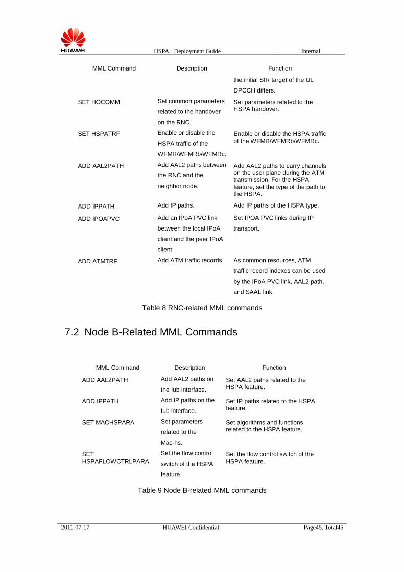
HSPA+ Deployment Guide Internal
2011-07-17 HUAWEI Confidential Page45, Total45
MML Command Description Function
the initial SIR target of the UL
DPCCH differs. SET HOCOMM Set common parameters
related to the handover
on the RNC.
Set parameters related to the HSPA handover.
SET HSPATRF Enable or disable the
HSPA traffic of the
WFMR/WFMRb/WFMRc.
Enable or disable the HSPA traffic of the WFMR/WFMRb/WFMRc.
ADD AAL2PATH Add AAL2 paths between
the RNC and the
neighbor node.
Add AAL2 paths to carry channels on the user plane during the ATM transmission. For the HSPA feature, set the type of the path to the HSPA.
ADD IPPATH Add IP paths. Add IP paths of the HSPA type. ADD IPOAPVC Add an IPoA PVC link
between the local IPoA
client and the peer IPoA
client.
Set IPOA PVC links during IP
transport.
ADD ATMTRF Add ATM traffic records. As common resources, ATM
traffic record indexes can be used
by the IPoA PVC link, AAL2 path,
and SAAL link.
Table 8 RNC-related MML commands
7.2 Node B-Related MML Commands
MML Command Description Function
ADD AAL2PATH Add AAL2 paths on
the Iub interface. Set AAL2 paths related to the HSPA feature.
ADD IPPATH Add IP paths on the
Iub interface. Set IP paths related to the HSPA feature.
SET MACHSPARA Set parameters
related to the
Mac-hs.
Set algorithms and functions related to the HSPA feature.
SET HSPAFLOWCTRLPARA
Set the flow control
switch of the HSPA
feature.
Set the flow control switch of the HSPA feature.
Table 9 Node B-related MML commands


![OWA333010 WCDMA HSPA+ Principles RAN11 ISSUE1.11.Ppt [Last Saved by User]](https://static.fdocuments.net/doc/165x107/55cf98ec550346d0339a7b6d/owa333010-wcdma-hspa-principles-ran11-issue111ppt-last-saved-by-user.jpg)