Raman-shifted Eye-safe Aerosol Lidar (REAL) in 2010...
13
Raman-shifted Eye-safe Aerosol Lidar (REAL) in 2010: Instrument Status and Two-component Wind Measurements Shane D. Mayor Department of Physics California State University Chico Chico, California, 95929 USA ABSTRACT This paper and corresponding seminar given on 20 September 2010 at the 16th International School for Quantum Electronics in Nesebar, Bulgaria, will describe the key hardware aspects of the Raman-shifted Eye-safe Aerosol Lidar (REAL) and recent advances in extracting two-component wind vector fields from the images it produces. The REAL is an eye-safe, ground-based, scanning, elastic aerosol backscatter lidar operating at 1.54 microns wavelength. Operation at this wavelength offers several advantages compared to other laser wavelengths includ- ing: (1) maximum eye-safety, (2) invisible beam, (3) superior performance photodetectors compared with those used at longer wavelengths, (4) low atmospheric molecular scattering when compared with operation at shorter wavelengths, (5) good aerosol backscattering, (6) atmospheric transparency, and (7) availability of optical and photonic components used in the modern telecommunations industry. A key issue for creating a high-performance direct-detection lidar at 1.5 microns is the use of InGaAs avalanche photodetectors that have active areas of at most 200 microns in diameter. The small active area imposes a maximum limitation on the field-of-view of the receiver (about 0.54 mrad full-angle for REAL). As a result, a key requirement is a transmitter that can produce a pulsed (>10 Hz) beam with low divergence (<0.25 mrad full-angle), high pulse-energy (>150 mJ), and short pulse-duration (<10 ns). The REAL achieves this by use of a commercially-available flashlamp-pumped Nd:YAG laser and a custom high-pressure methane gas cell for wavelength shifting via stimulated Raman scattering. The atmospheric aerosol features in the images that REAL produces can be tracked to infer horizontal wind vectors. The method of tracking macroscopic aerosol features has an advantage over Doppler lidars in that two compo- nents of motion can be sensed. (Doppler lidars can sense only the radial component of flow.) Two-component velocity estimation is done by computing two-dimensional cross-correlation functions (CCFs) and noting the displacement of the peak of the CCF with respect to the origin. Motion vectors derived from this method are compared with coincident sonic anemometer measurements at 1.6 km range. Preliminary results indicate the method performs best when the atmosphere is stable with light winds. Keywords: lidar, aerosol, wind, atmosphere 1. BACKGROUND AND RECENT EVENTS The Raman-shifted Eye-safe Aerosol Lidar (REAL, http://phys.csuchico.edu/lidar) is an elastic backscatter aerosol lidar operating at a wavelength of 1.54 microns. It was developed at the National Center for Atmospheric Research (NCAR) between 2001 and 2007 and was moved to California State University Chico in 2008. 1 Figure 1 shows a photograph of the instrument located at the university’s 800-acre Agricultural Teaching and Research Center (ATRC). The instrument was moved from the older shipping container on the left to the newer container on the right in 2009. 2 Previous field deployments of the instrument (Pentagon Shield, 3 T-REX, 4 CHATS, 5 as examples) were conducted with the instrument housed in the older container which had several problems including sources of dust, leaks, and lack of space. The new container is a custom optical laboratory designed specifically for field deployment of a scanning lidar. It features a substantially improved interior environment for the instrument including a spacious optical table (4.3 m long by 1.2 m wide and 0.45 m thick) and an air conditioning system that uses an exterior heat exchanger in order to eliminate air exchange with the outdoors. This greatly reduces contamination of the interior from dust and insects. An IQ-Air Health Pro Plus HEPA Author e-mail: [email protected]
-
Upload
nguyentuyen -
Category
Documents
-
view
216 -
download
0
Transcript of Raman-shifted Eye-safe Aerosol Lidar (REAL) in 2010...
Raman-shifted Eye-safe Aerosol Lidar (REAL) in 2010:Instrument Status and Two-component Wind Measurements
Shane D. Mayor
Department of PhysicsCalifornia State University Chico
Chico, California, 95929 USA
ABSTRACT
This paper and corresponding seminar given on 20 September 2010 at the 16th International School for QuantumElectronics in Nesebar, Bulgaria, will describe the key hardware aspects of the Raman-shifted Eye-safe AerosolLidar (REAL) and recent advances in extracting two-component wind vector fields from the images it produces.The REAL is an eye-safe, ground-based, scanning, elastic aerosol backscatter lidar operating at 1.54 micronswavelength. Operation at this wavelength offers several advantages compared to other laser wavelengths includ-ing: (1) maximum eye-safety, (2) invisible beam, (3) superior performance photodetectors compared with thoseused at longer wavelengths, (4) low atmospheric molecular scattering when compared with operation at shorterwavelengths, (5) good aerosol backscattering, (6) atmospheric transparency, and (7) availability of optical andphotonic components used in the modern telecommunations industry. A key issue for creating a high-performancedirect-detection lidar at 1.5 microns is the use of InGaAs avalanche photodetectors that have active areas of atmost 200 microns in diameter. The small active area imposes a maximum limitation on the field-of-view of thereceiver (about 0.54 mrad full-angle for REAL). As a result, a key requirement is a transmitter that can producea pulsed (>10 Hz) beam with low divergence (<0.25 mrad full-angle), high pulse-energy (>150 mJ), and shortpulse-duration (<10 ns). The REAL achieves this by use of a commercially-available flashlamp-pumped Nd:YAGlaser and a custom high-pressure methane gas cell for wavelength shifting via stimulated Raman scattering. Theatmospheric aerosol features in the images that REAL produces can be tracked to infer horizontal wind vectors.The method of tracking macroscopic aerosol features has an advantage over Doppler lidars in that two compo-nents of motion can be sensed. (Doppler lidars can sense only the radial component of flow.) Two-componentvelocity estimation is done by computing two-dimensional cross-correlation functions (CCFs) and noting thedisplacement of the peak of the CCF with respect to the origin. Motion vectors derived from this method arecompared with coincident sonic anemometer measurements at 1.6 km range. Preliminary results indicate themethod performs best when the atmosphere is stable with light winds.
Keywords: lidar, aerosol, wind, atmosphere
1. BACKGROUND AND RECENT EVENTS
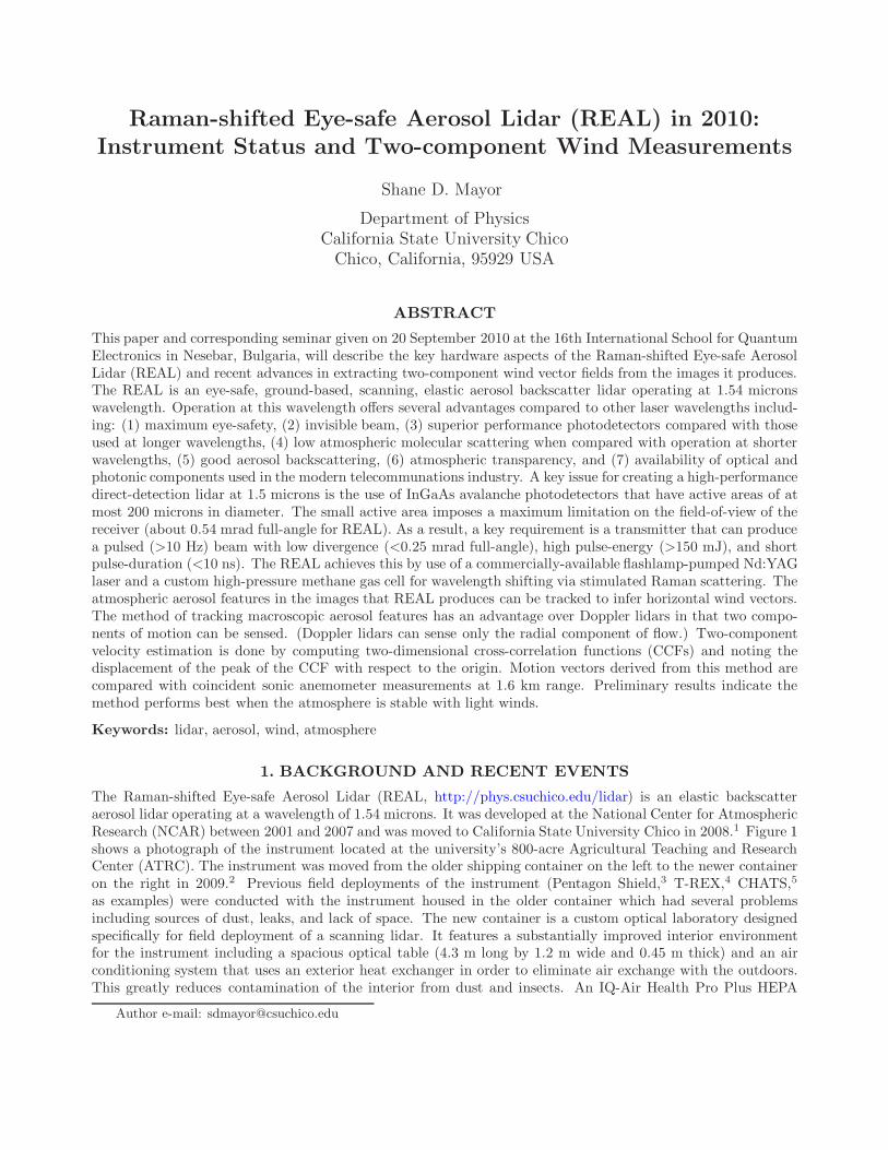
The Raman-shifted Eye-safe Aerosol Lidar (REAL, http://phys.csuchico.edu/lidar) is an elastic backscatteraerosol lidar operating at a wavelength of 1.54 microns. It was developed at the National Center for AtmosphericResearch (NCAR) between 2001 and 2007 and was moved to California State University Chico in 2008.1 Figure 1shows a photograph of the instrument located at the university’s 800-acre Agricultural Teaching and ResearchCenter (ATRC). The instrument was moved from the older shipping container on the left to the newer containeron the right in 2009.2 Previous field deployments of the instrument (Pentagon Shield,3 T-REX,4 CHATS,5
as examples) were conducted with the instrument housed in the older container which had several problemsincluding sources of dust, leaks, and lack of space. The new container is a custom optical laboratory designedspecifically for field deployment of a scanning lidar. It features a substantially improved interior environmentfor the instrument including a spacious optical table (4.3 m long by 1.2 m wide and 0.45 m thick) and an airconditioning system that uses an exterior heat exchanger in order to eliminate air exchange with the outdoors.This greatly reduces contamination of the interior from dust and insects. An IQ-Air Health Pro Plus HEPA
Author e-mail: [email protected]
Shane
Typewritten Text
Shane
Typewritten Text
Shane
Typewritten Text
Copyright SPIE 2010. Proceedings of the 16th International School for Quantum Electronics (ISQE). Vol. 7747, doi:10.1117/12.883454.
Shane
Typewritten Text
Shane
Typewritten Text
Shane
Typewritten Text
Shane
Typewritten Text
Shane
Typewritten Text
Shane
Typewritten Text
Shane
Typewritten Text
Shane
Typewritten Text
Shane
Typewritten Text
Shane
Typewritten Text
Shane
Typewritten Text
Shane
Typewritten Text
Shane
Typewritten Text
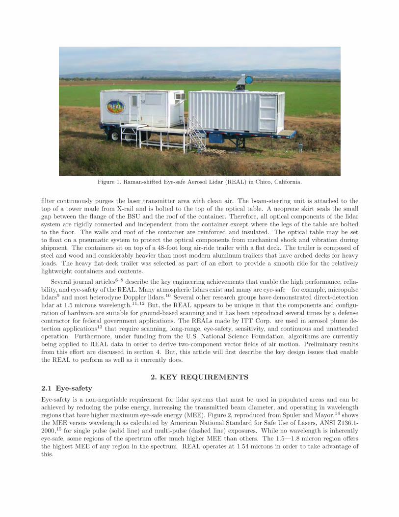
Figure 1. Raman-shifted Eye-safe Aerosol Lidar (REAL) in Chico, California.
filter continuously purges the laser transmitter area with clean air. The beam-steering unit is attached to thetop of a tower made from X-rail and is bolted to the top of the optical table. A neoprene skirt seals the smallgap between the flange of the BSU and the roof of the container. Therefore, all optical components of the lidarsystem are rigidly connected and independent from the container except where the legs of the table are boltedto the floor. The walls and roof of the container are reinforced and insulated. The optical table may be setto float on a pneumatic system to protect the optical components from mechanical shock and vibration duringshipment. The containers sit on top of a 48-foot long air-ride trailer with a flat deck. The trailer is composed ofsteel and wood and considerably heavier than most modern aluminum trailers that have arched decks for heavyloads. The heavy flat-deck trailer was selected as part of an effort to provide a smooth ride for the relativelylightweight containers and contents.
Several journal articles6–8 describe the key engineering achievements that enable the high performance, relia-bility, and eye-safety of the REAL. Many atmospheric lidars exist and many are eye-safe—for example, micropulselidars9 and most heterodyne Doppler lidars.10 Several other research groups have demonstrated direct-detectionlidar at 1.5 microns wavelength.11,12 But, the REAL appears to be unique in that the components and configu-ration of hardware are suitable for ground-based scanning and it has been reproduced several times by a defensecontractor for federal government applications. The REALs made by ITT Corp. are used in aerosol plume de-tection applications13 that require scanning, long-range, eye-safety, sensitivity, and continuous and unattendedoperation. Furthermore, under funding from the U.S. National Science Foundation, algorithms are currentlybeing applied to REAL data in order to derive two-component vector fields of air motion. Preliminary resultsfrom this effort are discussed in section 4. But, this article will first describe the key design issues that enablethe REAL to perform as well as it currently does.
2. KEY REQUIREMENTS
2.1 Eye-safety
Eye-safety is a non-negotiable requirement for lidar systems that must be used in populated areas and can beachieved by reducing the pulse energy, increasing the transmitted beam diameter, and operating in wavelengthregions that have higher maximum eye-safe energy (MEE). Figure 2, reproduced from Spuler and Mayor,14 showsthe MEE versus wavelength as calculated by American National Standard for Safe Use of Lasers, ANSI Z136.1-2000,15 for single pulse (solid line) and multi-pulse (dashed line) exposures. While no wavelength is inherentlyeye-safe, some regions of the spectrum offer much higher MEE than others. The 1.5—1.8 micron region offersthe highest MEE of any region in the spectrum. REAL operates at 1.54 microns in order to take advantage ofthis.

Single pulse
Multiple pulses
1.54 microns
VISIBLE
UV IR
Figure 2. Reproduced from Spuler and Mayor, 2007.14 Maximum eye-safe energy versus wavelength as calculated byAmerican National Standard for Safe Use of Lasers, ANSI Z136.1-2000, for the conditions shown. The solid curveis calculated for a single shot exposure. The dashed curve is calculated for multiple shots, or stationary laser beamconditions, with exposure times based on the natural aversion time of the human eye: 0.25 s and 10 s for inside andoutside the visible wavelength region, respectively.
2.2 Full overlap
A very important design requirement for any atmospheric lidar is that the receiver field of view (FOV) completelysurround, or overlap, the laser beam as shown in the top diagram in Fig. 3. The bottom diagram in Fig. 3 showsthe result when the laser beam is too divergent: it illuminates regions of the atmosphere that the receiver cannotsee. Not only is such an arrangement wasteful of the transmitted energy, it creates an additional problem ofneeding to determine an overlap function that is necessary to eliminate the one-over-range-squared dependencethat is inherent in any direct-detection backscatter lidar signal. With full overlap, as shown in the top diagram,the overlap function rapidly increases to, and remains at, one with increasing range. We have found with REAL,where the transmitter and receiver do not share the telescope, that it is most practical to have the receiverFOV at least twice as divergent as the laser beam. This makes it easier in practice to locate and achieve fulloverlap. The transmit beam is directed up and into the beam steering unit by a 4-inch by 5.6-inch diameterelliptical mirror that is positioned in the shadow of the telescope’s secondary mirror. This “launch mirror” is ona piezo-electric tip-tilt stage. Therefore, the transmit beam can be electronically scanned within the receiver’sFOV to insure that it indeed within it.
Full overlap can be achieved by reducing the laser beam divergence or increasing the receiver FOV. Thereceiver FOV can be maximized during design with custom optics, however it will be limited by the diameterof the active area of the photodetector. Large diameter detectors allow for large FOVs and small diameterdetectors restrict the FOV. For REAL, we found InGaAs avalanche photodetectors (APDs) have significantlybetter performance than InGaAs PINs. Unfortunately, InGaAs APDs have small active areas (200 micronsdiameter at most) thereby restricting the FOV. As a result, a challenge in creating REAL was to identify alaser that could generate pulsed laser radiation in the 1.5—1.8 micron region with sufficiently low divergence.Use of optical parametric oscillators (OPOs) was explored, but it was concluded that the divergence could notbe reduced sufficiently, even with beam expansion, to be less than what could practically be achieved for thereceiver FOV.16 Therefore, a commercially available Nd:YAG laser was used with a custom gas wavelengthconverter. This combination of pump and wavelength converter is described in detail by Spuler and Mayor(2007).14 Alternative approaches that also capitalize on stimulated Raman scattering in methane are describedby Hooper et al.17 and Trickl.18

TRANSMITTER
RECEIVER
TRANSMITTER
RECEIVER
Blue = Receiver FOV
Red = Transmit beam
Incomplete Overlap
Full Overlap
Wasted
Illumination
φ θ
θφ
<
>
Figure 3. Examples of proper overlap (top) and incomplete overlap (bottom) for an atmospheric lidar system.
The REAL transmitter begins with a commercially available, flashlamp pumped, Nd:YAG laser (a ContinuumSurelite III). It produces approximately 800 mJ of laser radiation at 1064 nm at 10 Hz pulse repetition frequency.The pump beam is directed through an optical isolator and a beam reducer before being directed into the Ramancell. Although the beam is weakly convergent in the cell, it is not focused in the cell. Focusing the pump beamresults in the breakdown of the gas medium and sooting on the cell windows. In addition to the high energypump beam, a continuous-wave injection seed beam is directed into Raman cell. The wavelength of the seedbeam is at the first Stokes line resulting from stimulated Raman scattering of 1.064 radiation in methane of 1.54microns. The cell is pressurized with 9.5 atm of methane and 4.1 atm of argon. The argon serves as a buffergas. Four prisms are used in the cell for 5 passes of the beam. Surfaces of the prisms, and windows of the cell,are oriented at the Brewster angle to minimize reflection without the use of anti-reflection (AR) coatings. Theuse of prisms instead of mirrors allows avoidance of high reflection (HR) coatings. We found the AR and HRcoatings to be a point of weakness in earlier designs. Tiny foreign particles on the surfaces or hot-spots in thebeam could cause the coatings at those points to fail.
The design of the wavelength converter in the REAL transmitter has received significant attention. Inaddition to the coating-free windows and prisms, a series of 8 axial fans circulate the gas and push it through thebeam plane. This moves thermal blooms—that would otherwise result in slight variations in the beam pointingdirection, lower divergence, and poorer beam quality—out of the way. Downstream of the Raman cell, a prismis used to separate the residual 1.064 micron pump beam from the first Stokes beam at 1.54 microns. The pumpbeam is stopped by a beam dump while the Stokes beam is expanded in diameter and directed over to the launchmirror. The divergence of the transmit beam can be adjusted by changing the distance between the two lensesof the beam expander.
We found through many hours of experience of using the REAL transmitter in a field environment that keyfactors for consistent performance include maintaining constant temperature and clean air. These factors arein general not a problem for laboratories in buildings but can become significant in mobile housings where it
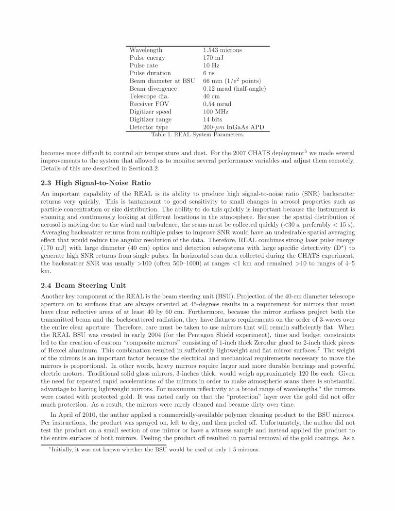
Wavelength 1.543 micronsPulse energy 170 mJPulse rate 10 HzPulse duration 6 nsBeam diameter at BSU 66 mm (1/e2 points)Beam divergence 0.12 mrad (half-angle)Telescope dia. 40 cmReceiver FOV 0.54 mradDigitizer speed 100 MHzDigitizer range 14 bitsDetector type 200-µm InGaAs APD
Table 1. REAL System Parameters.
becomes more difficult to control air temperature and dust. For the 2007 CHATS deployment5 we made severalimprovements to the system that allowed us to monitor several performance variables and adjust them remotely.Details of this are described in Section3.2.
2.3 High Signal-to-Noise Ratio
An important capability of the REAL is its ability to produce high signal-to-noise ratio (SNR) backscatterreturns very quickly. This is tantamount to good sensitivity to small changes in aerosol properties such asparticle concentration or size distribution. The ability to do this quickly is important because the instrument isscanning and continuously looking at different locations in the atmosphere. Because the spatial distribution ofaerosol is moving due to the wind and turbulence, the scans must be collected quickly (<30 s, preferably < 15 s).Averaging backscatter returns from multiple pulses to improve SNR would have an undesirable spatial averagingeffect that would reduce the angular resolution of the data. Therefore, REAL combines strong laser pulse energy(170 mJ) with large diameter (40 cm) optics and detection subsystems with large specific detectivity (D�) togenerate high SNR returns from single pulses. In horizontal scan data collected during the CHATS experiment,the backscatter SNR was usually >100 (often 500–1000) at ranges <1 km and remained >10 to ranges of 4–5km.
2.4 Beam Steering Unit
Another key component of the REAL is the beam steering unit (BSU). Projection of the 40-cm diameter telescopeaperture on to surfaces that are always oriented at 45-degrees results in a requirement for mirrors that musthave clear reflective areas of at least 40 by 60 cm. Furthermore, because the mirror surfaces project both thetransmitted beam and the backscattered radiation, they have flatness requirements on the order of 3-waves overthe entire clear aperture. Therefore, care must be taken to use mirrors that will remain sufficiently flat. Whenthe REAL BSU was created in early 2004 (for the Pentagon Shield experiment), time and budget constraintsled to the creation of custom “composite mirrors” consisting of 1-inch thick Zerodur glued to 2-inch thick piecesof Hexcel aluminum. This combination resulted in sufficiently lightweight and flat mirror surfaces.7 The weightof the mirrors is an important factor because the electrical and mechanical requirements necessary to move themirrors is proportional. In other words, heavy mirrors require larger and more durable bearings and powerfulelectric motors. Traditional solid glass mirrors, 3-inches thick, would weigh approximately 120 lbs each. Giventhe need for repeated rapid accelerations of the mirrors in order to make atmospheric scans there is substantialadvantage to having lightweight mirrors. For maximum reflectivity at a broad range of wavelengths,∗ the mirrorswere coated with protected gold. It was noted early on that the “protection” layer over the gold did not offermuch protection. As a result, the mirrors were rarely cleaned and became dirty over time.
In April of 2010, the author applied a commercially-available polymer cleaning product to the BSU mirrors.Per instructions, the product was sprayed on, left to dry, and then peeled off. Unfortunately, the author did nottest the product on a small section of one mirror or have a witness sample and instead applied the product tothe entire surfaces of both mirrors. Peeling the product off resulted in partial removal of the gold coatings. As a
∗Initially, it was not known whether the BSU would be used at only 1.5 microns.

result of this accident, new BSU mirrors with a honeycomb internal structure for lightness and durable enhancedaluminum coatings for the specific wavelength of REAL are being fabricated at the time of this writing. Deliveryof the new mirrors is expected in early 2011.
3. OTHER USEFUL CAPABILITIES
3.1 Polarization Sensitivity
In 2005, backscatter depolarization sensitivity was added to the REAL. It was done by improving the linearpolarization purity of the transmitter and adding a polarization rotator, polarization beam splitter cube andsecond detection channel in the receiver. Details of the upgrades and results of field testing are described inMayor et al.8 To summarize, the REAL transmitter is now capable of producing linearly polarized laser radiationwith a 10,000:1 purity. Unfortunately, due to the angle that the beam is projected on to the launch mirror, it was(and remains) likely not linearly polarized upon entering the BSU. Furthermore, when the BSU is not directedhorizontally, differential phase delay from the BSU mirrors results in a systematic error of the depolarizationratio that is a function of azimuth and elevation angle. As a result, the backscatter depolarization ratios are notabsolute. The polarization characteristics of the beam exiting the BSU were not measured. In the future thisshould be done with a polarimeter.
The above however is not to say that the backscatter depolarization ratios do not have value. As shown inMayor et al.,8 the system shows a very clear difference in depolarization ratios between controlled wet and dryaerosol plumes near the ground. Similar changes in backscatter depolarization ratio have been observed in waterclouds aloft. In the future, opto-mechanical components could be added to the system to rotate the polarizationvector to maintain a beam with constant linear polarization in the atmosphere.
3.2 Continuous and Unattended Operation
Recognizing the expense and inconvenience of requiring a person to be present at the lidar in order to operateit, software and hardware was added to the REAL in late 2006 and early 2007, just prior to CHATS,5 to enablenearly continuous and unattended operation.19 The most significant of the hardware additions was a laser beamprofiling system. The CCD camera of the beam profiler was positioned to intercept the 1064 nm pump beamleakage through a 45-degree turning mirror after the Raman-cell. The beam profiler CCD camera was connectedto a Windows PC that was connected to a network in the lidar container. Beam profiler software installed on thePC enabled continuous monitoring of the position, diameter, and shape of the pump beam. The beam profilersoftware recorded these characteristics so that we could see trends or identify problems. In addition, several airtemperature sensors were installed and interfaced with the lidar’s data acquisition system. The data acquisitionsoftware, written in Labview, was modified to record pump laser pulse energy, Stokes pulse energy, temperaturesof the Raman cell and indoor air, and Raman cell gas pressure in an ASCII data file once per minute. Resultsare shown in Fig. 4. In addition, the data acquisition software was modified to communicate with the Stokesinjection seed and Nd:YAG lasers. RealVNC R© software was installed on both computers that were connected toa network hub and an internet connection. This provided us with remote desktop control of the two computersfrom other locations. During CHATS, that took place in Dixon, California, we monitored the system throughthe internet connection from Boulder, Colorado. Several visits were made to the lidar during the three monthperiod to restart electrical devices that shut off due to power interruptions. However, during CHATS, about1850 hours of data were collected, an 85 percent “up-time”. Typically, we logged into the REAL computers onceor twice a day to check the system status. Occasionally, we increased the flash-lamp voltage through the remotecomputer control of the Nd:YAG laser.
In addition to remote control, the data acquisition software, which also sends instructions and receives datafrom the BSU, was modified so that sequences of different types of scans could be performed. For example, acommon scan strategy at CHATS was to repeatedly collect one PPI and one RHI so that both horizontal andvertical cross-sectional animations of the atmosphere could be obtained. The complete set of REAL scans in theform of images and animations can be obtained on line at http://phys.csuchico.edu/lidar.
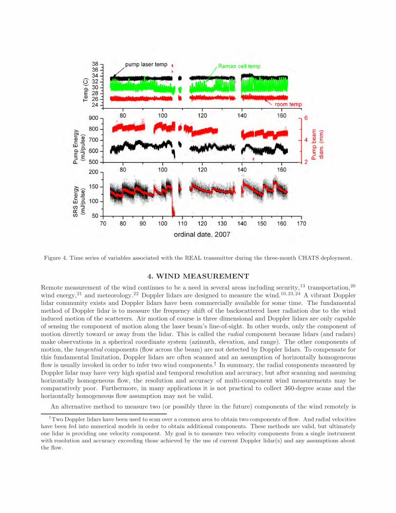
Figure 4. Time series of variables associated with the REAL transmitter during the three-month CHATS deployment.
4. WIND MEASUREMENT
Remote measurement of the wind continues to be a need in several areas including security,13 transportation,20
wind energy,21 and meteorology.22 Doppler lidars are designed to measure the wind.10,23,24 A vibrant Dopplerlidar community exists and Doppler lidars have been commercially available for some time. The fundamentalmethod of Doppler lidar is to measure the frequency shift of the backscattered laser radiation due to the windinduced motion of the scatterers. Air motion of course is three dimensional and Doppler lidars are only capableof sensing the component of motion along the laser beam’s line-of-sight. In other words, only the component ofmotion directly toward or away from the lidar. This is called the radial component because lidars (and radars)make observations in a spherical coordinate system (azimuth, elevation, and range). The other components ofmotion, the tangential components (flow across the beam) are not detected by Doppler lidars. To compensate forthis fundamental limitation, Doppler lidars are often scanned and an assumption of horizontally homogeneousflow is usually invoked in order to infer two wind components.† In summary, the radial components measured byDoppler lidar may have very high spatial and temporal resolution and accuracy, but after scanning and assuminghorizontally homogeneous flow, the resolution and accuracy of multi-component wind measurements may becomparatively poor. Furthermore, in many applications it is not practical to collect 360-degree scans and thehorizontally homogeneous flow assumption may not be valid.
An alternative method to measure two (or possibly three in the future) components of the wind remotely is
†Two Doppler lidars have been used to scan over a common area to obtain two components of flow. And radial velocitieshave been fed into numerical models in order to obtain additional components. These methods are valid, but ultimatelyone lidar is providing one velocity component. My goal is to measure two velocity components from a single instrumentwith resolution and accuracy exceeding those achieved by the use of current Doppler lidar(s) and any assumptions aboutthe flow.
by use of either cross-correlation25,26 or optical flow algorithms.26–29 In this paper, I will focus on the results ofthe cross-correlation method. These results were also recently presented at the 25th International Laser RadarConference.25 The reader is referred to the conference paper by Derian et al.29 for results of the application ofdense estimation optical flow to the same REAL data.
The cross-correlation technique has been applied to aerosol lidar data several times previously.30–37 It wasalso applied to weather radar data38 and satellite images.39 The most recent of these papers37 showed two-component vector fields with 250 m horizontal resolution over areas as large as 60 km2. These vectors howeverwere the result of large amounts of temporal averaging of many cross-correlation functions—up to 41 minutesin one case—in order to obtain mean properties of an offshore wind field. Furthermore, the lidar used inMayor and Eloranta37 was not eye-safe and the scans were not coincident with any independent forms of windmeasurement for validation. In the present work, no temporal averaging of the cross-correlation functions wasperformed. Moreover, the following results were collected with an eye-safe system and a micro-meteorologicaltower was located within the lidar scan plane for validation. This data set enables a comprehensive evaluationof the technique that will be conducted over the next two years under a grant from the U.S. National ScienceFoundation. Details of the algorithm used are in a paper presented at the 25th International Laser RadarConference.25 In this paper, just two brief cases are presented. More information on the cases can be found inpapers presented at the 24th and 25th ILRCs25,40 and a journal article currently in press.41
4.1 21 March 2007
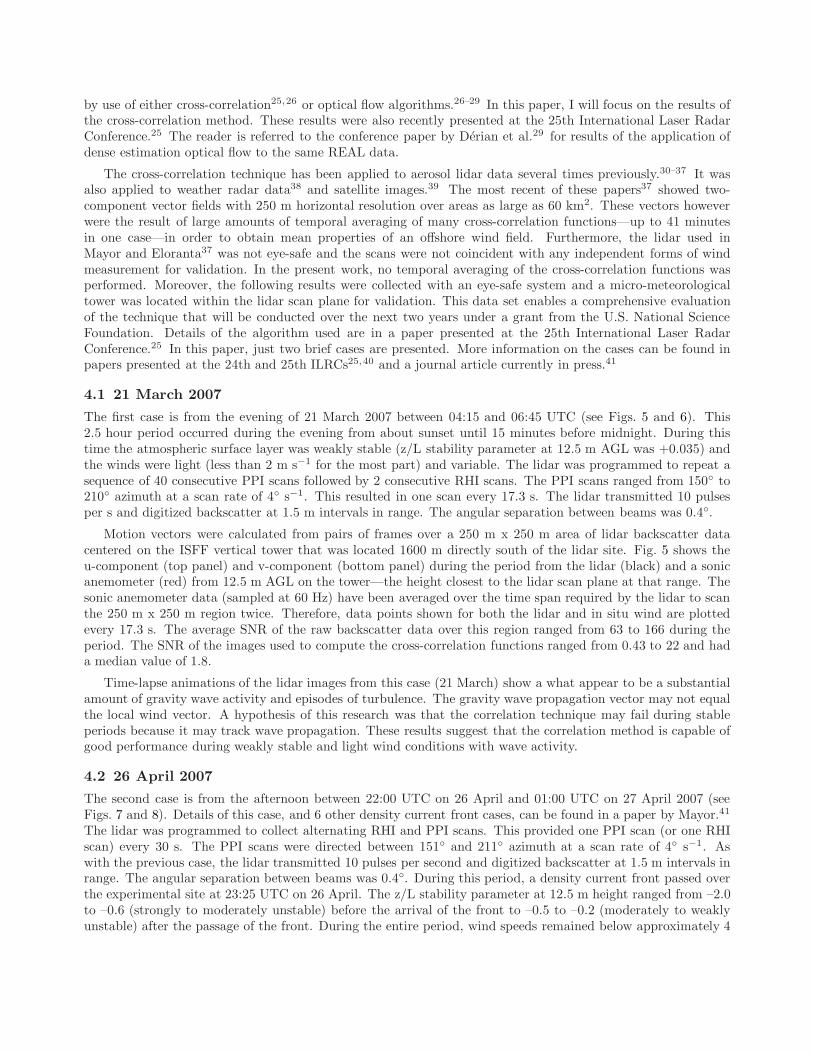
The first case is from the evening of 21 March 2007 between 04:15 and 06:45 UTC (see Figs. 5 and 6). This2.5 hour period occurred during the evening from about sunset until 15 minutes before midnight. During thistime the atmospheric surface layer was weakly stable (z/L stability parameter at 12.5 m AGL was +0.035) andthe winds were light (less than 2 m s−1 for the most part) and variable. The lidar was programmed to repeat asequence of 40 consecutive PPI scans followed by 2 consecutive RHI scans. The PPI scans ranged from 150◦ to210◦ azimuth at a scan rate of 4◦ s−1. This resulted in one scan every 17.3 s. The lidar transmitted 10 pulsesper s and digitized backscatter at 1.5 m intervals in range. The angular separation between beams was 0.4◦.
Motion vectors were calculated from pairs of frames over a 250 m x 250 m area of lidar backscatter datacentered on the ISFF vertical tower that was located 1600 m directly south of the lidar site. Fig. 5 shows theu-component (top panel) and v-component (bottom panel) during the period from the lidar (black) and a sonicanemometer (red) from 12.5 m AGL on the tower—the height closest to the lidar scan plane at that range. Thesonic anemometer data (sampled at 60 Hz) have been averaged over the time span required by the lidar to scanthe 250 m x 250 m region twice. Therefore, data points shown for both the lidar and in situ wind are plottedevery 17.3 s. The average SNR of the raw backscatter data over this region ranged from 63 to 166 during theperiod. The SNR of the images used to compute the cross-correlation functions ranged from 0.43 to 22 and hada median value of 1.8.
Time-lapse animations of the lidar images from this case (21 March) show a what appear to be a substantialamount of gravity wave activity and episodes of turbulence. The gravity wave propagation vector may not equalthe local wind vector. A hypothesis of this research was that the correlation technique may fail during stableperiods because it may track wave propagation. These results suggest that the correlation method is capable ofgood performance during weakly stable and light wind conditions with wave activity.
4.2 26 April 2007
The second case is from the afternoon between 22:00 UTC on 26 April and 01:00 UTC on 27 April 2007 (seeFigs. 7 and 8). Details of this case, and 6 other density current front cases, can be found in a paper by Mayor.41
The lidar was programmed to collect alternating RHI and PPI scans. This provided one PPI scan (or one RHIscan) every 30 s. The PPI scans were directed between 151◦ and 211◦ azimuth at a scan rate of 4◦ s−1. Aswith the previous case, the lidar transmitted 10 pulses per second and digitized backscatter at 1.5 m intervals inrange. The angular separation between beams was 0.4◦. During this period, a density current front passed overthe experimental site at 23:25 UTC on 26 April. The z/L stability parameter at 12.5 m height ranged from –2.0to –0.6 (strongly to moderately unstable) before the arrival of the front to –0.5 to –0.2 (moderately to weaklyunstable) after the passage of the front. During the entire period, wind speeds remained below approximately 4
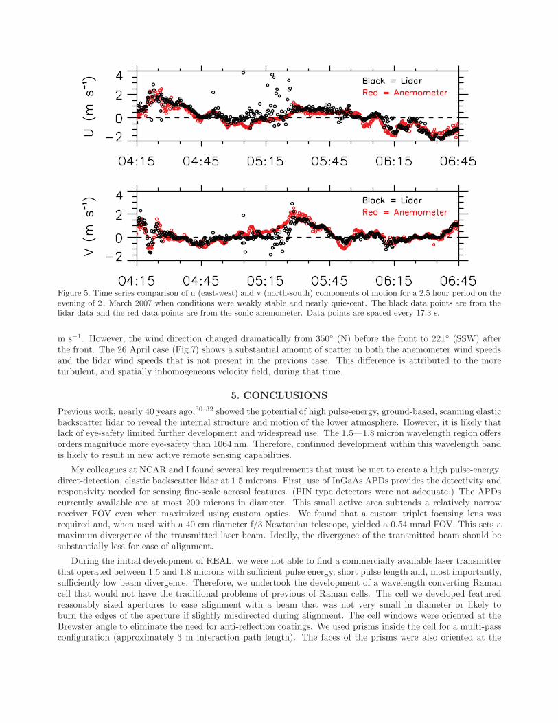
Figure 5. Time series comparison of u (east-west) and v (north-south) components of motion for a 2.5 hour period on theevening of 21 March 2007 when conditions were weakly stable and nearly quiescent. The black data points are from thelidar data and the red data points are from the sonic anemometer. Data points are spaced every 17.3 s.
m s−1. However, the wind direction changed dramatically from 350◦ (N) before the front to 221◦ (SSW) afterthe front. The 26 April case (Fig.7) shows a substantial amount of scatter in both the anemometer wind speedsand the lidar wind speeds that is not present in the previous case. This difference is attributed to the moreturbulent, and spatially inhomogeneous velocity field, during that time.
5. CONCLUSIONS
Previous work, nearly 40 years ago,30–32 showed the potential of high pulse-energy, ground-based, scanning elasticbackscatter lidar to reveal the internal structure and motion of the lower atmosphere. However, it is likely thatlack of eye-safety limited further development and widespread use. The 1.5—1.8 micron wavelength region offersorders magnitude more eye-safety than 1064 nm. Therefore, continued development within this wavelength bandis likely to result in new active remote sensing capabilities.
My colleagues at NCAR and I found several key requirements that must be met to create a high pulse-energy,direct-detection, elastic backscatter lidar at 1.5 microns. First, use of InGaAs APDs provides the detectivity andresponsivity needed for sensing fine-scale aerosol features. (PIN type detectors were not adequate.) The APDscurrently available are at most 200 microns in diameter. This small active area subtends a relatively narrowreceiver FOV even when maximized using custom optics. We found that a custom triplet focusing lens wasrequired and, when used with a 40 cm diameter f/3 Newtonian telescope, yielded a 0.54 mrad FOV. This sets amaximum divergence of the transmitted laser beam. Ideally, the divergence of the transmitted beam should besubstantially less for ease of alignment.
During the initial development of REAL, we were not able to find a commercially available laser transmitterthat operated between 1.5 and 1.8 microns with sufficient pulse energy, short pulse length and, most importantly,sufficiently low beam divergence. Therefore, we undertook the development of a wavelength converting Ramancell that would not have the traditional problems of previous of Raman cells. The cell we developed featuredreasonably sized apertures to ease alignment with a beam that was not very small in diameter or likely toburn the edges of the aperture if slightly misdirected during alignment. The cell windows were oriented at theBrewster angle to eliminate the need for anti-reflection coatings. We used prisms inside the cell for a multi-passconfiguration (approximately 3 m interaction path length). The faces of the prisms were also oriented at the

Figure 6. Two component vector flow field for a pair of scans collected on the evening of 21 March 2007. The vectors arespaced every 50 m in x and y and are the result of 250 m x 250 m areas. The vectors are superimposed on one of the twohigh-pass median filtered backscatter intensity images that were used to compute the vectors.
Brewster angle. This eliminated the need for any AR or HR coatings in the cell. The cell uses a series of axialfans to circulate the CH4 and Ar gas mixture. Finally, the pump beam is not focused in the cell and the cell isinjection seeded at the Stokes wavelength. We found all of these things necessary to reliably convert 1064 nmpump to 1543 nm with reasonable efficiency, beam characteristics, and reliability. If pumped correctly, the cellsuffers from no contamination or deterioration over time.
Several other technologies have been key to enabling reliable, unattended, and nearly-continuous operationof the REAL. First, the environment in which the instrument operates must be temperature stabilized andfree of dust and insects. Second, laser beam diagnostics that are recorded and are able to be plotted from aremote location to identify problems and trends are critical. For example, a slow and steady decreasing pulseenergy is symptom of the natural deterioration of laser flash lamps and must be compensated for periodicallyby increasing the flash lamp voltage. Therefore, computer control of the pump laser’s power and cooling unit isrequired. Finally, uninterruptable power supplies are very valuable as small inconsistencies in electrical power tothe lidar site can cause one or more components to reset and cause a cascade of problems for the entire system.
In terms of wind measurement, preliminary results suggest that agreement of the vectors between correlationmethod and averaged sonic-anemometer data are best during light wind and stable conditions. High frequencyagreement between the two forms of air velocity measurements becomes poorer during windy and turbulentconditions. A comprehensive comparison is currently being conducted. In the future, we plan to compute highresolution vector flow fields in real-time. Such a capability may have value in the short-term prediction of aerosolplume transport and disperson, for example. Real-time execution means completing all calculations within thetime required to perform one scan (typically about 15 s). Therefore, we recently began exploring methods tooptimize the execution of the program including multithreading, CPU SIMD instructions, and general purpose

Figure 7. Time series comparison of u (east-west) and v (north-south) components of motion during a 3-hour period onthe afternoon of 26 April 2007. During this period, a density current front passed over the site causing a near reversalof the v-component. The atmosphere during this case was unstable and turbulent. The black data points are from thelidar data using a 500 m x 500 m box centered on the ISFF vertical tower and the red data points are from the sonicanemometer on the tower. Data points are spaced every 30 s.
graphics processing units (GPGPU).
ACKNOWLEDGMENTS
REAL was developed at NCAR with funding from the US National Science Foundation. Dr. Scott Spuler andMr. Bruce Morley developed and deployed the instrument. The recent work of deriving vectors from the CHATSdata using the correlation technique and this paper and presentation at the 16th ISQE were made possible byGrant 0924407 from NSF’s Physical and Dynamic Meteorology Program.
REFERENCES
[1] Kintisch, E., “Turbulent times for climate model,” Science 321, 1032–1034 (2008).[2] McAfee, T. R., Griffo, C. F., Petrova-Mayor, A., and Mayor, S. D., “Rebuilding the Raman-shifted Eye-safe
Aerosol Lidar (REAL),” in [California State University Chico College of Natural Sciences 5th Annual PosterSession ], (2009).
[3] Warner, T., Benda, P., Swerdlin, S., Knievel, J., Argenta, E., Aronian, B., Balsley, B., Bowers, J., Carter,R., Clark, P. A., Clawson, K., Copeland, J., Crook, A., Frehlich, R., Jensen, M. L., Liu, Y., Mayor, S.,Meillier, Y., Morley, B., Sharman, R., Spuler, S., Storwold, D., Sun, J., Weil, J., Xu, M., Yates, A., andZhang, Y., “The Pentagon Shield Field Program: Toward Critical Infrastructure Protection,” Bull. Amer.Meteor. Soc. 88, 167–176 (2007).
[4] DeWekker, S. F. J. and Mayor, S. D., “Observations of atmospheric structure and dynamics in the OwensValley of California with a ground-based, eye-safe, scanning aerosol lidar,” J. Clim. Appl. Meteor. 48,1483–1499 (2009).
[5] Patton, E. G., Horst, T. W., Sullivan, P. P., Lenschow, D. H., Oncley, S. P., Brown, W. O. J., Burns, S. P.,Guenther, A. B., Held, A., Karl, T., Mayor, S. D., Rizzo, L. V., Spuler, S. M., Sun, J., Turnipseed, A. A.,Allwine, E. J., Edburg, S. L., Lamb, B. K., Avissar, R., Calhoun, R., Kleissl, J., Massman, W. J., U, K.
Figure 8. Two component vector flow field for one pair of scans collected on 26 April 2007. The vectors are spaced every50 m in x and y and are the result of 500 m x 500 m areas. The vectors are superimposed on one of the two high-passmedian filtered backscatter intensity images that was used to compute the vectors. The color scale of the backscatterdata has been adjusted so that the advancing marine airmass is blue and the airmass north of it is green.
T. P., and Weil, J. C., “The Canopy Horizontal Array Turbulence Study (CHATS),” Bull. Amer. Meteor.Soc. , Accepted (2010).
[6] Mayor, S. D. and Spuler, S. M., “Raman-shifted Eye-safe aerosol lidar (REAL),” Appl. Optics 43, 3915–3924(2004).
[7] Spuler, S. M. and Mayor, S. D., “Scanning eye-safe elastic backscatter lidar at 1.54 microns,” J. Atmos.Ocean. Technol. 22, 696–703 (2005).
[8] Mayor, S. D., Spuler, S. M., Morley, B. M., and Loew, E., “Polarization lidar at 1.54-microns and observa-tions of plumes from aerosol generators,” Opt. Eng. 46, DOI: 10.1117/12.781902 (2007).
[9] Spinhirne, J. D., “Micro pulse lidar,” IEEE Trans. Geosci. Remote Sensing 31, 48–55 (1993).[10] Grund, C. J., Banta, R. M., George, J. L., Howell, J. N., Post, M. J., Richter, R. A., and Weickman, A. M.,
“High-resolution Doppler lidar for boundary layer and cloud research,” J. Atmos. Ocean. Technol. 18,376–393 (2001).
[11] Carnuth, W. and Trickl, T., “A powerful eyesafe infrared aerosol lidar: Application of stimulated ramanbackscattering of 1.06 micron radiation,” Rev. Sci. Instrum. 65, 3324–3331 (1994).
[12] Spinhirne, J. D., Chudamani, S., Cavanaugh, J. F., and Bufton, J. L., “Aerosol and cloud backscatterat 1.06, 1.54, and 0.53 µm by airborne hard-target-calibrated Nd : YAG/ methane Raman lidar,” Appl.Optics 36, 3475–3490 (1997).
[13] Mayor, S. D., Benda, P., Murata, C. E., and Danzig, R. J., “Lidars: A key component of urban biodefense,”Biosecur. Bioterror. 6, 45–56, DOI: 10.1089 bsp.2007.0053 (2008).
[14] Spuler, S. M. and Mayor, S. D., “Raman shifter optimized for lidar at 1.5-micron wavelength,” Appl.Optics 46, 2990–2995 (2007).
[15] “American National Standard for Safe Use of Lasers,” Tech. Rep. Z136.1, Laser Institute of America (2000).
[16] Mamidipudi, P. and Killinger, D., “Optimal detector selection for a 1.5 micron ktp opo atmospheric lidar,”in [SPIE Conference on Laser Radar Technology and Applications IV ], 3707, 327–335, SPIE (1999).
[17] Hooper, W. P., Frick, G. M., and Michael, B. P., “Using backward raman scattering from coupled deuteriumcells for wavelength shifting,” Opt. Eng. 48, 084302–1–6 (2009).
[18] Trickl, T., “Upgraded 1.56 µm lidar at imkifu with 0.28 J/pulse,” Appl. Optics 49, 3732–3740 (2010).[19] Spuler, S. M. and Mayor, S. D., “Eye-safe aerosol lidar at 1.5 microns: progress towards a scanning lidar
network,” in [SPIE Lidar Remote Sensing for Environmental Monitoring VIII ], DOI: 10.1117/12.739519(2007).
[20] National Academy of Sciences, [Wake Turbulence: An Obstacle to Increased Air Traffic Capacity ], NationalAcademies Press, 500 Fifth Street, N.W., Washington, DC 20055 (2008).
[21] “And now, the electricity forecast,” The Economist Technology Quarterly 395(8686), 14–15 (12 June 2010).[22] National Academy of Sciences, [Why Weather Matters: Science and Service to Meet Critical Societal Needs ],
National Academies Press, 500 Fifth Street, N.W., Washington, DC 20055 (2010).[23] Post, M. J. and Cupp, R. E., “Optimizing a pulsed Doppler lidar,” Appl. Optics 29, 4115–4158 (1990).[24] Henderson, S. W., Hale, C. P., Magee, J. R., Kavaya, M. J., and Huffaker, A. V., “Eye-safe coherent laser
radar system at 2.1 micron using tm,ho:yag lasers,” Opt. Lett. 16, 773–775 (1991).[25] Mayor, S. D., “Horizontal motion vectors from cross-correlation: First application to eye-safe aerosol lidar
data from CHATS,” in [25th International Laser Radar Conference ], (2010).[26] Mayor, S. D., Derian, P., Heas, P., and Memin, E., “Two-component horizontal motion vectors from scanning
eye-safe aerosol lidar,” in [19th Symp. on Boundary Layers and Turbulence ], AMS (2010).[27] Horn, B. K. P. and Schunck, B. G., “Determining optical flow,” Artificial Intelligence 17, 185–203 (1981).[28] Corpetti, T., Memin, E., and Perez, P., “Dense estimation of fluid flows,” IEEE Trans. Pattern Analysis
Machine Intelligence 24, 365–380 (2002).[29] Derian, P., Heas, P., Memin, E., and Mayor, S. D., “Dense motion estimation from eye-safe aerosol lidar
data,” in [25th International Laser Radar Conference ], (2010).[30] Eloranta, E. W., King, J. M., and Weinman, J. A., “The determination of wind speeds in the boundary
layer by monostatic lidar,” J. Appl. Meteor. 14, 1485–1489 (1975).[31] Sroga, J. T., Eloranta, E. W., and Barber, T., “Lidar measurements of wind velocity profiles in the boundary
layer,” J. Appl. Meteor. 19, 598–605 (1980).[32] Kunkel, K. E., Eloranta, E. W., and Weinman, J., “Remote determination of winds, turbulence spectra
and energy dissipation rates in the boundary layer from lidar measurements,” J. Atmos. Sci. 37, 978–985(1980).
[33] Sasano, Y., Hirohara, H., Yamasaki, T., Shimizu, H., Takeuchi, N., and Kawamura, T., “Horizontal windvector determination from the displacement of aerosol distribution patterns observed by a scanning lidar,”J. Appl. Meteor. 21, 1516–1523 (1982).
[34] Hooper, W. P. and Eloranta, E. W., “Lidar measurements of wind in the planetary boundary layer: themethod, accuracy and results from joint measurements with radiosonde and kytoon,” J. Clim. Appl. Me-teor. 25, 990–1001 (1986).
[35] Kolev, I., Parvanov, O., and Kaprielov, B., “Lidar determination of winds by aerosol inhomogeneities:motion velocity in the planetary boundary layer,” Appl. Optics 27, 2524–2531 (1988).
[36] Schols, J. L. and Eloranta, E. W., “The calculation of area-averaged vertical profiles of the horizontal windvelocity from volume imaging lidar data,” J. Geophys. Res 97, 18395–18407 (1992).
[37] Mayor, S. D. and Eloranta, E. W., “Two-dimensional vector wind fields from volume imaging lidar data,”J. Appl. Meteor. 40, 1331–1346 (2001).
[38] Rinehart, R. E. and Garvey, E. T., “Three-dimensional storm motion detection by conventional weatherradar,” Nature 273, 287–289 (1978).
[39] Leese, J. A., Novak, C. S., and Clark, B. B., “An automated technique for obtaining cloud motion fromgeosynchronous satellite data using cross correlation,” J. Appl. Meteor. 10, 118–132 (1971).
[40] Mayor, S. D., “Observations of sea-breeze fronts and turbulence near the surface during stable conditions,”in [24th International Laser Radar Conference ], SO30–01 (2008).
[41] Mayor, S. D., “Observations of seven density current fronts in Dixon, California,” Mon. Wea. Rev. , InPress (2010).