Raise-boring experiences in the gold mines of the Anglo American ...
14
Raise-boring experiences in the gold mines of the Anglo American Corporation Group SYNOPSIS by J. W. Wilson* M.Se., M.I.M.M., F.S.A.I.M.M., M.A.I.M.E. and P. C. Graham** M.Se. (Eng.) Gold mining is being carried out at ever-increasing depths in South Africa. For reasons of safety and human comfort, it is becoming imperative for raises to be developed by means other than conventional drilling and blasting. Raise-boring is an attractive alternative method. Initial raise-boring experiences in South African gold mines showed disappointingly high costs due to the abrasivity and difficulty of drilling Witwatersrand quartzites. Consequently, a research and development project was instigated with the objective of making raise-boring an economically viable technique in hard abrasive rock. A Robbins 61R raise-borer was made available to the Research and Development team and a number of raises have been drilled. During these trials two advances in cutter design were tested. This paper presents the results obtained, including drilling costs, and provides details of the equipment used. SINOPSIS Met die steeds toenemende bedrywigheid van die Suid Afrikaanse goudmynbedryf wat ook in diepte onder- gronds toegeneem het, is daar gesoek na 'n metode wat veiliger is as die gebruiklike boor en skiet van 'n styg- gang. Om die styggang in te boor het geblyk 'n goeie plaasvervanger te wees. Aanvanklik was die resultate teleurstellend weens die hoe koste daaraan verbonde en dit het geblyk dat die hardheid en hoe druksterkte van die kwartsiet grootliks daarvoor verantwoordelik was. Daar is toe besluit op 'n navorsings-program om 'n metode te ontwikkel wat die boor van 'n styggang goedkoper maak. 'n 'Robbins 61R' styggangboor is beskik- baar gestel en 'n aantal eksperimentele gate is geboor. Hierdie artikel gee 'n weergawe van die resultate wat verkry is tesame met die koste aspek en toerusting wat gebruik is. INTRODUCTION This paper deals essentially with the experience of the Anglo American Corporation, Gold Division, Research and Development Department of raise-boring in hard abrasive rock, with particular reference to the drilling characteristics of the machine and the costs incurred during the drilling and reaming operations. It also summarises part of a comprehensive research and development programme currently under investigation, which will, it is hoped, provide detailed operating pro- cedures, maintenance schedules, organisation program- mes, activity times, prediction of future drilling rates and costs from the analyses of rock samples taken from underground. Achievements to date in the raise-boring programme have shown a significant reduction in costs compared to early raise-boring efforts and because of this, it is hoped that the experiences described in this paper may en- courage mining engineers in South Africa to reconsider raise-boring as a means of mechanising the arduous job of developing major ore-passes and similar types of steeply dipping excavations. With the wider use of raise-boring in the mining industry, more data will become available for assisting in the development of more economical methods and in making the technique more attractive to Mine Manage- ments. *Gold Division, Research and Development Engineer, Anglo American Corporation of South Africa, Limited. **Head, Engineering Section, Research and Development Department, Anglo American Corporation of South Africa, Limited. A BRIEF HISTORY OF RAISE-BORING IN SOUTH AFRICA Raise- boring was first introduced into South Africa in 1968 at the Doornfontein gold mine1, where it was clearly shown that it had a wide application, provided it could be made an economically attractive technique in the unique South African mining conditions. The biggest potential users of the technique in South Africa are the gold mines, and there are many applications, such as ore-passes, ventilation airways and short lift or hoisting sub-shafts. The boring principle is attractive because it offers the following advantages over conventional drilling and blasting methods: (i) Safer working conditions (ii) Speed of completion (iii) A hole is produced that has a more stable struc- tural shape, which is highly desirable in deep- level workings (iv) A hole is produced that has smooth sidewalls which have low frictional loss in ventilation airways, and reduces the likelihood of blockages in the ore-passes. Unfortunately, early experiences with raise-boring showed that the cost was disappointingly high, pri- marily because of the hard quartzite formations en- countered in the gold mines. The cutter cost associated with reaming holes in Witwatersrand quartzites was exceptionally high and the high forces generated by the boring machine often resulted in costly machine failures when insufficient care was taken during operation. Thus, in spite of the attraction of raise-boring, en. thusiasm has waned and only a few mines have main. JOURNAL OF THE SOUTH AFRICAN INSTITUTE OF MINING AND METALLURGY OCTOBER 1972 103
Transcript of Raise-boring experiences in the gold mines of the Anglo American ...

Raise-boring experiences in the gold minesof the Anglo American Corporation Group
SYNOPSIS
by J. W. Wilson* M.Se., M.I.M.M., F.S.A.I.M.M., M.A.I.M.E. and P. C. Graham** M.Se. (Eng.)
Gold mining is being carried out at ever-increasing depths in South Africa. For reasons of safety and humancomfort, it is becoming imperative for raises to be developed by means other than conventional drilling andblasting. Raise-boring is an attractive alternative method. Initial raise-boring experiences in South Africangold mines showed disappointingly high costs due to the abrasivity and difficulty of drilling Witwatersrandquartzites. Consequently, a research and development project was instigated with the objective of makingraise-boring an economically viable technique in hard abrasive rock. A Robbins 61R raise-borer was madeavailable to the Research and Development team and a number of raises have been drilled. During these trialstwo advances in cutter design were tested. This paper presents the results obtained, including drilling costs,and provides details of the equipment used.
SINOPSIS
Met die steeds toenemende bedrywigheid van die Suid Afrikaanse goudmynbedryf wat ook in diepte onder-gronds toegeneem het, is daar gesoek na 'n metode wat veiliger is as die gebruiklike boor en skiet van 'n styg-gang. Om die styggang in te boor het geblyk 'n goeie plaasvervanger te wees. Aanvanklik was die resultateteleurstellend weens die hoe koste daaraan verbonde en dit het geblyk dat die hardheid en hoe druksterkte vandie kwartsiet grootliks daarvoor verantwoordelik was. Daar is toe besluit op 'n navorsings-program om 'nmetode te ontwikkel wat die boor van 'n styggang goedkoper maak. 'n 'Robbins 61R' styggangboor is beskik-baar gestel en 'n aantal eksperimentele gate is geboor. Hierdie artikel gee 'n weergawe van die resultate watverkry is tesame met die koste aspek en toerusting wat gebruik is.
INTRODUCTION
This paper deals essentially with the experience of theAnglo American Corporation, Gold Division, Researchand Development Department of raise-boring in hardabrasive rock, with particular reference to the drillingcharacteristics of the machine and the costs incurredduring the drilling and reaming operations. It alsosummarises part of a comprehensive research anddevelopment programme currently under investigation,which will, it is hoped, provide detailed operating pro-cedures, maintenance schedules, organisation program-mes, activity times, prediction of future drilling rates andcosts from the analyses of rock samples taken fromunderground.
Achievements to date in the raise-boring programmehave shown a significant reduction in costs compared toearly raise-boring efforts and because of this, it is hopedthat the experiences described in this paper may en-courage mining engineers in South Africa to reconsiderraise-boring as a means of mechanising the arduous jobof developing major ore-passes and similar types ofsteeply dipping excavations.
With the wider use of raise-boring in the miningindustry, more data will become available for assistingin the development of more economical methods and inmaking the technique more attractive to Mine Manage-ments.
*Gold Division, Research and Development Engineer, AngloAmerican Corporation of South Africa, Limited.
**Head, Engineering Section, Research and DevelopmentDepartment, Anglo American Corporation of South Africa,Limited.
A BRIEF HISTORY OF RAISE-BORING IN SOUTHAFRICA
Raise- boring was first introduced into South Africa in1968 at the Doornfontein gold mine1, where it wasclearly shown that it had a wide application, providedit could be made an economically attractive techniquein the unique South African mining conditions. Thebiggest potential users of the technique in South Africaare the gold mines, and there are many applications,such as ore-passes, ventilation airways and short lift orhoisting sub-shafts.
The boring principle is attractive because it offers thefollowing advantages over conventional drilling andblasting methods:
(i) Safer working conditions(ii) Speed of completion
(iii) A hole is produced that has a more stable struc-tural shape, which is highly desirable in deep-level workings
(iv) A hole is produced that has smooth sidewallswhich have low frictional loss in ventilationairways, and reduces the likelihood of blockagesin the ore-passes.
Unfortunately, early experiences with raise-boringshowed that the cost was disappointingly high, pri-marily because of the hard quartzite formations en-countered in the gold mines. The cutter cost associatedwith reaming holes in Witwatersrand quartzites wasexceptionally high and the high forces generated by theboring machine often resulted in costly machine failureswhen insufficient care was taken during operation.
Thus, in spite of the attraction of raise-boring, en.thusiasm has waned and only a few mines have main.
JOURNAL OF THE SOUTH AFRICAN INSTITUTE OF MINING AND METALLURGY OCTOBER 1972 103

tained an interest in the use of raise-boring, and untilrecently, it has been the tendency only to use raise-boringin instances where conventional raising methods werenot possible. The reasons for high raise-boring costs havebeen mainly a result of:
(i) High capital costs and, consequently, amortiza-tion charges
(ii) High cutter costs in hard abrasive ground
(Hi) Costly machine failures due to inexpert handlingof the raise-boring machine and ancillary equip-ment.
Even though present raise-boring costs exceed thoseincurred in conventional raising methods, the raise-boring technique is still considered to be highly desirable
- especially where mining operations are being plannedto take place at depths of 3 952 metres (13000 ft) andultimately, to depths of 4560 metres (15000 ft). Atthese depths rock pressures and temperatures willprovide hazardous and unpleasant working conditionsand the introduction of mechanised means of creatingbox-holes, ventilation airways, and other steeply dippingexcavations will become increasingly more important -
if not imperative.
Furthermore, with the large capital expenditures re-quired for the opening up of new mines or extensions toexisting mines, the speed at which such projects arecompleted and production commences can have tre-mendous financial implications on the overall project.Raise- boring equipment provides a proven method ofachieving the required shortening of the developmentstage of a new mine.
For the above reasons the Gold Division Research andDevelopment Department embarked on a project toestablish raise-boring as an economically viable propo-sition in hard-rock formations. This necessitated thepurchase of a raise-borer from a Group contractor andthen carrying out a series of trials at Anglo AmericanCorporation gold mines.
In the first twelve months of operation, 11 holes werebored on a non-profit contracting basis using a Robbins61R raise-borer. This paper describes in general termssome of the experiences to date on machine performance,cutter performances and resulting costs for 1,82 metres(6 ft) and 2,13 metres (7 ft) raises bored.
RAISE-BORING TEAM AND THEIR DUTIES
It was considered that the choice of personnel forthe drilling team was of the utmost importance, and thatpersons with previous experience in raise-boring would
104 OCTOBER 1972
Fig. 1-Robbins 61R raise-borer on site at Western Holdings, Ltd. No. 1 shaft
JOURNAL OF THE SOUTH AFRICAN INSTITUTE OF MINING AND METALLURGY

not be coIlsidt:\red lor choice as itleitlbers 01 thl'l teaitl;M such personnel itlight have acquired experiencecontrary to good operating practice. At the tiitle ofteam selection it was also felt that it would be ad-vantageous if the itlachine operators could carry outthe necessary patloditJ itlatJhin(j itlafrit@riance and minorrunnihg repairs i h~nctJ; (Jnly qliaHfifJd artisans (fittersand ~lectrft:Jiati§) Wet'e si'Jlected, FurthtJhnot'e, having at~alli (Jf hf~h tJaBbl'e op\:\rators, it was possible to trainthelli to (Jbs\:\l'v\:\and record operating characteristics ofthe raise-borer as part of the Research and Developmentprogramme.
Eleven raises have been bored in the programme, andcomplete records of the following variables have beenmaintained - pressures, rates of penetration, motorcurrents, activity times, cutter wear and costs incurred.In addition, the operators test the effects of variations inpressure on reaming rates for every drill rod used ineach hole, and on occasions, the effects of applied thrustduring reaming on 'chip size' have been examined.
RAISE-BORER DESCRIPTION AND REQUIRE-MENTS
The Robbins 61R raise-borer consists of a fabricatedsteel base onto which 2 cylindrical guide columns aremounted and a crosshead which can travel up anddown the guide columns (see Figure 1). The crossheadcontains a drive jaw assembly which holds the drillrods; an epicyclic gearbox and an electric motor whichprovides rotation of the drill string. Drilling thrust andmovement of the crosshead along the guide columns iseffected by means of two hydraulic cylinders connectedbetween the base and the crosshead.
Electric power is supplied via a separate power packwhich contains the necessary transformers, control andswitch gear. Pressurised hydraulic fluid is supplied to theraise-borer from a hydraulic pack which incorporates atank, filters, pumps and all necessary valves. Thehydraulic pack also supplies hydraulic power to thepipe handler which facilitates the installation andremoval of drill rods from the machine. The pipe handlercan be clearly seen in Fig. 1. Control of all the machinefunctions is accomplished from a separate controlstation also shown in the illustration on previous page.
The machine specification and service requirements arelisted below:
Dip adjustmentPilot hole diameterDrill pipe
45 to 90° from horizontal280 mm (11")254 mm (10") diameter
1524 mm (60") diameter, shoul-der length, 194,7 kG/m, 131lb/ft weight934 kN (210000 lb) maximum
1 401 kN (310 000 lb) operating2 024 kN (455 000 lb) maximumPilot hole 455 mm/min (17,5")Reaming 265 mm/min (10,4")
1 800 mm/min (71 ")Two speed constant H.P. in-
duction motor 112 kW (750/
Pilot thrustReaming pull
Feed rates
Traverse rateElectric drive
Gear reducer drive
1 500 t.p;in. 150 H.P;) @50Hz
Planetary drive train with 3,61:shift ratio
8:16,30-60 r.p.m. @ 50 HzFun load at low speed 125,6
kNM (92500 ft/lb) @ 50 Hz380, 415, 440 or 550 volts A.C.
@ 50 Hz. 170 K.V.A.
22,8 m3/mm (800 c.f.m.) @ 60 to100 p.s.i.g. (4,14 to 6,89 Bar.)
37,8 litre/min (10 g.p.m.) @ 60to 100 p.s.i.g. (4,14 to 6,89Bar.)
Height: 5,5 m (18 ft)Length: 9 m (29,5 ft)Width: 5 m (16,4 ft)
Dt'ive speiolds
Drive torque
Electrical power
Air consumption
Water consumption
Excavationdimensions atMachine
REAMERS AND CUTTERS
Before presenting the results of reaming operations inthe holes drilled to d:1te, it is necessary to discussbriefly the various types of reamers and cutters com-mercially avaihble.
Reamers
There are three configurations of reamer - thestaged head or 'christmas tree' head, the 'flat head' andthe 'disc head'. Within these three categories, there areas many variations as there are cutter manufacturers,since each supplier manufactures his own unique sizerange and there is no interchangeability.
A typical 1,82 metre (6 ft) diameter staged head isshown in Figs. 2 and 3. This head consists of two sectionswhich are bolted together, a 28 cmx122 cm (11"X48")section and a 122 cm X 182 cm (48" X 72 ") section. Ifdesired, the 122 cm X 182 cm (48" X 72 ") stage can bereplaced by a 122 cmx213 cm (48"X84") stage. Thistype of reamer has an inherent weakness in the stembecause it is necessary to reduce the stem section inorder to accommodate the two top or inner cutters.
The 'flat head' shown in Fig. 4 represents a designimprovement on the staged head. In this design the twoinner cutters are positioned so that the reamer stemretains its full strength, and furthermore, the torquerequirements for the reamer are reduced. The 122 cm X182 cm (48" X72") or 122 cm x213 cm (48" X84") stagesremain the same as for the staged head.
In the trials, three reamers have been used; two can becategorised as 'flat heads' and the other, a disc type. Theflat heads used were the 'Reed' 28 cm X 122 cm (11" X48 ") coupled with a 122 cm X 182 cm (48" X 72 ") stage,and the 'Smith' 28 cmx122 cm (11"x48") which wasused with a 122 cm X 182 cm (48" X 72 ") stage and a122 cmx182 cm (48"x84") stage.
JOURNAL OF THE SOUTH AFRICAN INSTITUTE OF MINING AND METALLURGY OCTOBER 1972 t05

Fig. 2-1,22 m diam. 'Christmas Tree' reamer
Fig. 3-1,22 X 1,82 m reamer head stage
106 OCTOBER 1972 JOURNAL OF THE SOUTH AFRICAN INSTITUTE OF MINING AND METALLURGY

Fig. 4-1,22 m 'Flat Head' reamer stage
Disc Cutter Head
Fig. 5 shows a photograph of a disc cutter reamerbody. The main body of the reamer is a fabricated steelconstruction with the cutter saddles welded in theappropriate positions. The saddles are positioned insuch a manner that each cutter cuts in its own individualpath. The radial distance between each path is 6,35 cm(2t inches),
The reamers are all single staged, that is, a separatereamer is required for each diameter of hole to be cut.This disadvantage is slightly offset by the fact that it ispossible to remove the reamer stem or 'stinger'. Thus,only one stem needs to be maintained on inventory and
when the reaming head is dismantled, the transportdimensions of the reamer are considerably reduced.
Cutters
Raise-borer reaming heads are usuallyrolling cutters and three types of rollingcommercially available. They are:
(i) Milled tooth cutters
(ii) Kerf cutters
(Hi) Tungsten carbide insert cutters.
fitted withcutters are
Since the trials were conducted in hard rock, tungstencarbide insert cutters were used. Fig. 6 shows a typicalinsert cutter. The cutting principle is to fracture the rockby means of a spalling action when the individual insertsare pressed against the rock face at very high loads.To ensure that complete coverage of the rock face takesplace, the cutters in each radial row are mounted inpairs. In this way, the cutters are rolled across therock face so that the buttons of the second cutter breakout the rock left by the spaces between the button rowsof the first cutter.
Some manufacturers offer cutters with a choice ofinsert shape to suit specific rock formations.
Neoprene Lip Seal Cutters
At the start of the raise-boring programme, the onlycutters available for reaming hard rock formations wereequipped with neoprene lip bearing seals.
Fig. 7 shows a section of a typical neoprene seal cutterwith details of the bearings and seals. These seals havebeen found to have an operating life of about 60 hours,after which time it is normally necessary to lower thereaming head and remove the cutters for reconditioning.Since all of the raises bored in the raise- boring programmeexceeded 45 metres (150 ft) in length and the rate ofpenetration was usually of the order of 60 cm per hour(2 ft) a change of cutters during the reaming cycle wasobligatory.
The limiting factor in the life of these seals appears tobe the high operating temperature generated by thecutters during the reaming cycle. Since the seal materialis known to be adequate for operating temperatures of upto 121°C (250°F), it appears that the working tempera-ture at the cutters must exceed this figure. Experiencehas shown that when the cutters are used for periods inexcess of 60 hours seal failure often results. This in turncauses irreparable bearing damage due to the ingress ofdirt.
It can be seen in Fig. 7 that the cutter bearings aremade up of 3 sets of cylindrical rollers and one row ofballs, the balls being used to accommodate axial thrustand also provide accurate axial location.
This configuration of bearings is able to withstandhigh radial a mindpact loading. The inner race or journalof the cutter is made of heat-treated alloy steel and is
.JOURNAL OF THE SOUTH AFRICAN INSTITUTE OF MINING AND METALLURGY OCTOBER 1972 107
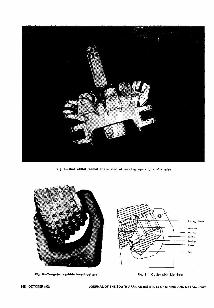
Fig. 5-Disc cutter reamer at the- start of reaming operations of a raise
Fig. 6- Tungsten carbide insert cutters
108 OCTOBER 1972
B...;n5 Ja I.
Lo.d Pin
B.'hinS'
S.ddl.
B !,
C........
s..1.
Fig. 7 - Cutter with Lip Seal
JOURNAL OF THE SOUTH AFRICAN INSTITUTE OF MINING AND METALLURGY

precision ground to a smooth finish. 'rhe cutter bodywhich is forged from high alloy steel and then carburizedand hardened, provides the outer race of the bearing.Repairs to the bearing may be performed by replacingthe balls, rollers and if necessary, the journal. Oversizerollers and balls cannot be fitted in the cutter and incases of excessive wear to the outer race or cutter body,the cutter must be scrapped. On occasions where sealfailures have occurred before the anticipated 60 hours,bearing failure and cutter body damage has occurred.In these eases the damage has been irreparable andcostly.
Double Caterpillar Seal Cutters
After the first two holes were completed, a new bearingseal development became available. This seal, known asthe double Caterpillar seal, consists of a metal-to-metalseal with excellent sealing properties and the ability towithstand very high temperatures. Fig. 8 shows acutter equipped with double 'Cat.' seals. This lattercutter type features a bearing configuration consistingof two rows of cylindrical rollers and a row of balls.The cutter body and journal or sleeve function as theouter and inner races of the bearings respectively.
0."..B..".,
0 ,
,_"..B..,,","-'-'..-
Y.....
Fig. 8-Double "Cat" seal cutter
Experience with the double 'Cat.' seal type cuttershas shown that the seals appear to have a life of ap-proximately 150 hours. In most practical situations thisis sufficient to complete raises in hard rock stratawithout the need to lower the reamer or cause damageto the cutters. A close examination of damaged cuttershas revealed that seal damage which occurs after 150hours of operation is a result of the excessive wear ofthe steel balls in the control race and this wear ultimatelycracks the seal rings. These steel balls are the sole meansof accommodating axial thrust.
The double 'Cat.' seal cutters have been used to reameight of the eleven holes bored to date, including all five2,13 metre (7 ft) diameter ore-passes. Apart from anincrease in total cost to dress a reaming head, there canbe no doubt that cutters equipped with double Cater-pillar seals have proved that they are suitable for raise-
boring work in hard, abrasive quartzites. tn fact, it isfair to say that the development of this type of cutterand seal have played a significant part in reducingcutter costs in recent times.
Disc Cutters
The latest cutter development to be tried in SouthAfrica is the disc cutter developed by Robbins ofSeattle, US.A. The first trials with disc cutters havebeen very promising, but there is still doubt as to theirsuitability for cutting very hard rocks. A disc cutterconsists of a renewable cutting ring and cutter body.The latter houses the bearings and seals. Photographs oftypical disc cutters are shown in Figs. 9 and 10. Thecutting rings presently in use are made of alloy steel andcase-hardened to a depth of 6,25 mm (0,25 inches).
Rings made from other materials are also feasible-in fact, rings made with tungsten carbide inserts arebeing considered. When the rings are worn they can bereplaced, thus extending the life of the cutter. Cutterrings are available with apex angles of 60°,75°,90° and105°. The selected apex angle depends upon the rock
Fig. 9-Single ring disc cutter after completing raise in shale
Fig. 10 - Double ring disc cutter after completing raise inshale
JOURNAL OF THE SOUTH AFRICAN INSTITUTE OF MINING AND METALLURGY OCTOBER 1972 109

...
~.;iz~MO:;-
"" "~::;.,2..
:8~8bi)°.s~s~oJ
"...
1"1::;;::;;
~0re
~1"1::;;Po<0...
~1"1AAZ-<:
~~r:z:1°~~JXlI"I<00~~
z'"'A1"1...><ii1A001"100
~r«000
~0
'"'Eo<
~Po<
0:;-0:;-..c::..c::................. .~~~~
;"::s
... .....c::..c::
SS............0:>0:>
00
~ §.~ .........., ..., .~
".
"'..c::"J~tv
p.0 .:<>
"01.t:.~ ..,~ "oJ S~ Z
::s
"""0:>"":;000:>IQ00... ...
000
"'0""""
""IQ"""0~~~~IQM............
d0
~oJ
E<El~<>0
~
'"0;;...
~bDS
8.:gp..~P::S
~~,!:J,!:J.., ..,~~
..c::..,..."bD'"a~
~S
, ,o:>~
M""............~~
OM",,'0;-~M
...
"..,
1~.$ SA
"~""00,......
".S::s ..,bi)
;§
'0~S".....,~
".
"""0~Z......
110 OCTOBER 1972
"M0:>~~......
00
0:;- 0:;-0:;-0:;-
~ ~~~, ...""
0000......~ ~~~
... ...........c:: ~..c::..c::
S SSSIQIQ
0
~O~
""""'"0"":;""'"
00;-~0...
0,Q
""
IQ
~'IQMIQ
'0 '~...~M
IQ""",:......
00MM~~......
00M
00""......M"'"""C:::......
......
;:;-
"...'N...;;.,
"0',,01"d..c::om,!:IN=~ d ~p.jS".~ ..,;;..,
".,dp.o<f1tm~""
~~"...'N~.,0'
", , ,~001Q", ""..................
~00......~ ~~~
'"..;IQ
000o~oo0:>MM
" "~~
""~......
""00,......
~"...m...d~'iiJ~p.
..,'i:>
"~p.""AS".....,"i$
""M
0:;-0:;-0:;-..c::..c::..c::........................, . .00"""""~~~
.....c::..c::..c::
SSS~~O
"""'M0"":;"":;
IQ
~'IQMIQ
'0 '~...~M ......
IQ
,:......
00M
00"".....M"'"""C:::"""......
"...'N~.,
"0',,01"d..c::-om,!:IN=~d~p.jS
~'iiJ ~.,dp.o<f1tm~""
"0~~
, , ,~oooo~ ~..................
0..;M......
000";~,QIQM~
"~""~......
..,'i:>
"~1t"AS"...rJJ
~~
0:;-0:;-0:;-0:;-..c::..c::..c::..c::................................. . . .O:>""""'M:::.~~~
lLE:lJ lJSSSSO""""M~1Q~00000'0
~001Q1Q0;-"":;";0;-~IQ~""0 0 0 0............OOMO...o'~o""..................
M~~M~IQOOMM
M""":'6":'6IQ
0:>"""0:>......
MM
~~'"O
~~;""'"
...JXI
~ 8. ~.S~~j~
"0~~
, , , ,L"'OOMO:>M~~~~ ~
Ei................. .~
~:::.
IlJ lJ 1SS""IQIQM
00'
OIQIQ
000:>'00'""~MSSSI000000";""""""
MOIQ"""'0:>;:%~IM",IQ..................
~15o.~N~"";; 1~., -~O' P.
~~ ~~~~s~j~c3
" """" I"~OO~ ~~"'~~ ~
~~ ......
0:;-0:;-..c::..c::................. .~O:>~:::.
I 1~~ss
"'......IQ~00
OIQIQ
00' ~ 00'""~MSSSI000000";""""""
MOIQ"""'0:>;:%~IM",IQ..................
~15o.~N~ bD~;;
l'!"., ~~O' P.
~~ ~~~~sjj~c3
~~~~, , , ,~o~o:::.~~:::.
0...IQ
0000,Q";':.,;
""......
0:;-0:;-..c::..c::................. .""IQ~~
lJlJsso~000000
000000'
""""0 0......00"":;0;-
""
MM
"""............
.0":'~O:>......
"d0N
""""'"0~.~~JXI~.s"
oJ~::S
"~0:>......
~~
0:;-0:;-..c::..c::................. .00'"~~... ...
..c::..c::
SSo~~'"00
000000
""""0 0......00
'0;-
""
MM
"""............
.0":'~O:>
......
"d0N
""""'"0~.~~JXI~.s"
oJ~::S
"M0~
, ,MO:>MO:>~~
"'"'"~00
'"
..,§o:;-
c::~;--,,~~,0"",-:=......
~~
0'"O~ z:::: S~
S~~o.,;~0 ......
-gM lis~
~"'"O.., ; 1;j"~","'1;j ...::; bi)bD'O ~gl§ ~ S
:iJ~oJ.t: ""Ai$~~ 6
0:;-..c::.........M......
~IQ0 ,
.§~
~
0,......~0...
0..;
""
0..;M......
0000
0"""""';""
~......
00~~0..;00
0000",,": "":;",,'
""""
"~M.........
..,bD.S'"0'0~
S"...
~~
~
~O:>MO:>~~
~......
'"
0000
00
~0.......§~
~
M00
""~0:>......
"~""00,......
~...m...d
"'"0
£IQ
"~M.........
..,bD
.S'"0'0~
S"...
~0:>
0dO~
00"":;0
00
"~M.........
~.S'"0'0~d...
"...
~
'"
~..c::m~~S~~~p.o"...
~.p."'p.~~
......
~~
"~M.........
~;.a'0~@
...rJJ
~00
" "00~IQ~~
0~......
0
'"~00:>'............
~
00
;0......
0,QIQ
"~ "~""00
:;M.........
rJJ
'i
~~
1t"A
~~
i$
~2m...§
'"0'iiJ
"...p.
0..................
JOURNAL OF THE SOUTH AFRICAN INSTITUTE OF MINING AND METALLURGY

TABLE II
DRILLING TIMES
PILOTING REAMINGHole Hole
I
TOTALNo. length Drilling Rod handling Drilling Rod handling
(metres) Hrs. Mins. Hrs. Mins. Hrs. Mins. Hrs. Mins. Hrs. Mins.
81,3 37 05 16 45 142 35 10 42 207 07
2 54,9 32 40 11 34 104 45 7 21 156 20
3 134,0 71 20 15 30 163 00 14 39 264 29
4 134,0 64 32 11 43 141 34 13 53 231 42
5 84,0 38 05 7 50 142 25 10 20 198 40
6 52,0 32 29 13 37 125 43 5 39 177 28
7 49,0 26 21 4 11 88 55 5 34 125 02
8 91,0 47 10 9 05 107 10 7 15 170 40
9 90,0 39 32 16 03 98 11 6 40 160 26
10 116,0 51 32 13 01 70 33 12 39 147 45
11 55,0 27 00 7 10 181 32 9 13 224 55
.JOURNAL OF THE SOUTH AFRICAN INSTITUTE OF MINING AND METALLURGY OCTOBER 1972 111
to be cut, where the more acute angle ring is used forsoft rock. In contrast to tungsten carbide button insertcutters, only one disc or ring is placed in each cuttingradius on the reaming head. The pitch between eachcutting path is 62 mm (2t inches). The designers haveseen fit to mount double rings (see Fig. 10) on cutters atcertain positions on the reaming head. However, ingeneral, most cutter bodies have only single rings. Therings are shrunk onto the cutter bodies which are madefrom cast steel and house the bearings and seals. Theaxial and radial cutting loads are accommodated by twocommercial taper roller bearings. These bearings are adistinct improvement on the bearings of cutters pre-viously mentioned, since they have better loadingcharacteristics and life expectancy. A further advantageof these bearings is that they may also be completelyreplaced if necessary. Ingress of dirt into the bearings isprevented by means of double 'Cat.' seals, which haveproven reliability. The manufacturers claim that thecutting rings have a life expectancy of up to 125 hours,whilst the bearings can be expected to run for 500 hourswithout attention. At this point in time it may be pos-sible to re-adjust the clearances and still obtain ad-ditional cutter life. Therefore, a cutter body shouldoutlast several sets of rings.
Disc cutters are less expensive than tungsten carbidebutton cutters and the facility of renewing the cuttingrings makes the use of disc cutters most attractive.However, as mentioned earlier, the use of disc cuttersmay only be possible in the softer quartzites. The cutter-bearing journals have trunnion ends which are clampedonto saddles on the reamer body, a photograph of whichis shown in Fig. 5. The 1,82 metre (6 ft) diameter reamershown has 11 cutters and 14 cutting edges, 3 of thecutters being fitted with double rings.
DRILLING PERFORMANCES
Geology
Table I summarises the physical characteristics of eachhole drilled and reamed with the Robbins 61R machine,and also the mean reaming rates at a constant thrust of89 kN (20000 lb) per cutter (arithmetic average) in thevarious geological formations.
It can be seen from this table that a wide variety ofrock formations within the Witwatersrand series havebeen bored so far in the drilling programme. The uni-axial compressive strengths of the rocks bored variesfrom 62 MN/m2 (9000 p.s.i.) to 412 MN/m2 (61000p.s.i.). In general, it can be seen that the rocks withlower compressive strengths reamed more easily. How-ever, it has not been possible to determine a reliablerelationship between compressive strengths and reamingrates. This is probably a result of the inherent variablenature of the rock formations themselves, and theinfluence of other factors such as rock hardness, localstress conditions and rock fracture zones in the drillingpath. Even though the 61R raise-borer is essentiallydesigned to drill 1,82 metre (6 ft) diameter raises, it wasfound to be suitable for reaming 2,13 metre (7 ft) dia-meter raises, especially in soft rock where the rates ofpenetration were surprisingly good. In geologically hardformations, the rates of penetration attained in boring2,13 metre (7 ft) diameter raises were disappointing.Penetration rates in these rocks would probably havebeen better if more machine thrust had been available.However, during the trials, the drilling operationsinvariably took place at close to the maximum allowablecutter loading on the particular reaming head in use.

---t -::::::J 0
0--:I=~c;-+
"'"
~000
;:>=::::.
C>
~8
~~c-+-C>::::::Jc:/)
~8
Rate0-g
of PBnetration Cms pBr HourIn..0 .....
0.0 '"0'"0 .-
0
t.0.0-
~
~
.....
Fig.-11 Upper Elsburg Bastard Conglomerate & Middling. Hole no. 1. Penetration rates v/a reamer thrusts for1,82 m. diam. reamer head
112 OCTOBER 1972 JOURNAL OF THE SOUTH AFRICAN INSTITUTE OF MINING AND METALLURGY

Rate of P Bnetration In Cms per Hour0
14'"'
.'"'
...- co co 0 0 0 0
§','?",~.
'(1'"i:,~
\:=rl- ,-;g ' ,-{.
\,--:7 ,.= ,'"c:.? J'. , \c:-i'" \ ' ~,
\- ,). \-. ..~co .;~\~~
co
~\11.
~C)
:~ 1\ ~\- ':..:z: ...8 o_~
~\~~..:~-~,~0- '\c-t'"" .-C)
.~\.~~~.-i 0- 0 .\ ~o-
\, ~\.....
0- ~...
\- ~-i~,0, !!- \v.... \
\\ \~t.0-
f\ '\'
\ ' ""' ,,
"\ " ,
" ,
I
Fig. 12-Upper tootwall-2(UF.). - Lower portion. Hole no. 5 Penetration rates vis reamer thrustc tor 1,82 m. diam.reamer head
JOURNAL OF THE SOUTH AFRICAN INSTITUTE OF MINING AND METALLURGY OCTOBER 1972 113

Uniaxial com-pressive strength
Hole Diameter rangeNo. metres
MN/m2
1 1,82 (6') 157 to 4122 1,82 (6') 173 to 338
3 1,82 (6') 121 to 2384 1,82 (6') 121 to 2385 1,82 (6') 69 to 3576 2,13 (7 ') 139 to 3207 2,13 (7 ') 139 to 3208 2,13 (7 ') 62 to 1939 2,13 (7') 62 to 193
10 1,82 (6') 121
11 2,13 (7') 163 to 283
Total cutterCutter wear Cutter repair Cutter cost per metre
Cutter type cost/m cost/m ancillarycost/m
R R R R c
T.C. Lip Seal 249,70 93,30 3,40 346,40
" " "333,00 34,60 3,40 371,00
T.C. Double 'Cat' Seal 105,50 5,28 6,03 116,81
" " " "99,00 7,03 2,55 108,58
" " " "91,50 4,60 8,82 104,92
" " " "118,50 12,47 16,70 147,67
" " " "165,07 11,96 14,89 191,92
" " " "55,24 6,90 6,61 68,75
" " " "55,70 3,74 5,97 65,41
Disc 32,14 13,14 - 45,28
T.C. Double 'Cat' Seal 173,10 4.59 890 186,59
Hole Length Pilot bit Reamer Site TotalNo. metres Diameter cutters Maintenance Preparation Labour cost
R/m R/m R/m R/m R/m R/m
1 81 1,82 (6') 10,00 346,40 35,80 6,40 26,50 425,102 55 1,82 (6') 12,30 371,00 39,70 8,10 50,60* 481,703 134 1,82 (6') 5,00 116,80 27,60 7,10 21,60 178,104 134 1,82 (6') 10,00 108,60 24,20 4,50 20,50 167,805 84 1,82 (6') 4,70 104,90 33,10 5,20 40,60* 188,506 52 2,13 (7') 12,80 147,70 47,80 9,10 35,10 252,507 49 2,13 (7') 13,50 191,90 35,70 7,70 25,00 273,808 91 2,13 (7') 14,70 68,80 26,30 8,50 34,40 152,709 90 2,13 (7') 18,70 65,40 25,00 6,80 32,40 148,30
10 116 1,82 (6') 8,70 45,30 17,80 6,00 36,10 113,9011 55 2,13 (7') 20,90 186,60 57,30 7,00 50,00 321,80
Drilling Times
Table II provides a brief summary of the drilling timesfor each of the eleven holes. This Table refers to machineoperating times only and does not include delays andset-up times. Holes 1 and 2 were drilled with lip sealcutters which resulted in additional rod handling andcutter-change times of 12 hours 50 minutes and 16 hours22 minutes respectively.
DRILLING CHARACTERISTICS
Throughout the boring trials, penetration rate testswere conducted at various applied thrusts for each of the1,52 metre (5 ft) rod lengths reamed. Figs. 11 and 12show typical plots of penetration rate against thrust fortwo rods in different geological horizons. The completeresults have not been presented here as they are beyondthe scope of this paper. It is sufficient to say that thedetailed investigations indicate that the relationshipbetween penetration rate and thrust in hard rocks islinear through the normal operating range of the Rob-bins 61R raise-borer machine. However, at this stagethere is some doubt as to whether this linear trend willcontinue at higher thrusts.
COSTS
Because reaming costs represent between 60 and 80per cent of the total raise-boring costs, considerable
attention has been paid to reaming operations and waySand means of reducing the associated costs.
Table III shows the reamer cutter costs incurred inthe various holes completed to date, together with thecutter types used and the compressive strengths of therock formations bored through. In this Table, no pilothole cutter costs have been considered, and cutterancillary costs consist of consumable items required todress the reamer, such as load pins.
At a cutter cost of R45,28 per metre (RI3,50 per foot)the disc cutters have proved to be by far the best todate, especially when compared with cutter costs ofR116,81 and RI08,58 per metre (R35,61 per foot andR33,10 per foot) for holes 3 and 4 respectively, in thesame type of ground where tungsten carbide insertcutters were used. A glance at Table III shows themarked decrease in cutter costs which occurred sincethe incept of the Research and Development programme.These encouraging cost reductions are essentially due tocutter design improvements, particularly the intro-duction of the double 'Cat.' seal. It should be noted,however, that cutter costs are still dependent on thenature of the rock to be bored.
The overall costs for each raise are summarised inTable IV. Accurate costs for raise-boring by othersprior to the commencement of the trials are not avail-able. However, the costs of the first two raises may be
TABLE IIIREAMER CUTTER COSTS
TABLE IVTOTAL COST SUMMARY
114 OCTOBER 1972
*Drilled in a sinking shaft and subject to delays imposed by shaft sinking requirements.
JOURNAL OF THE SOUTH AFRICAN INSTITUTE OF MINING AND MET ALl.URGY

considered to be rl:!presl:!Iitative of this period becausesbnilar cutters were used.
SUMMARY AND CONCLUSIONS
One of the major factors contributing to the successfulreduction in the overall costs and smooth operationduring the raise-drilling trials has been the choice ofoperators. No major breakdowns which would normallyresult in damage to the machine or equipment, haveoccurred. This has been primarily due to the establish-ment, through initial experiences, of sound drilling pro-cedures, the stringent application of these, and timelymaintenance of the machine by the operators them-selves.
The Robbins 61R machine has proved to be capable ofdrilling 2,13 metre (7 ft) diameter holes up to about91 metres (300 ft) in length, in relatively soft ground,and, compared with the experiences derived by somecontractors, the cutter costs have been reduced signifi-cantly. It should be noted, however, when boring2,13 metre (7 ft) holes in the harder formations thepenetration rates have been generally poor, which hasresulted in unacceptably high cutter and labour costs.It would appear that it is only worth while attempting2,13 metre (7 ft) diameter raises in hard rock with buttoninsert cutters with double 'Cat.' seals, where the ex-pected reaming time will not exceed 150 hours.
The results to date indicate that cutter costs are, tosome extent, dependent on the uniaxial compressivestrength of the rock being bored. However, it is apparentthat the compressive strength of the rock is not the onlyfactor influencing cutter costs or penetration rates. Re-search work has now commenced on attempting torelate the penetration rates and costs achieved to date,with indices based on rock abrasiveness and button testsfor rock samples taken from the rock formations throughwhich boring has already taken place.
The advent of the double Caterpillar bearing seal incutter design has proved to be the most significant factorin the reduction of cutter costs in the rock types drilledby the Research and Development Department. Thereduction in overall cost brought about by this develop-ment has appreciably increased the appeal of raise-boring to gold mine managers - so much so, that theResearch and Development Department raise-borer hassufficient work on hand to keep it busy for the nextthree years. This is in spite of the fact that raise-boringis at present still more costly than conventional methods,although the gap between conventional methods andraise-boring has closed considerably.
What are the prospects for the future At the time ofwriting, a number of new cutter developments arealready on the horizon and the prospects of lower overallcosts and better penetration rates are extremely favour-able. The first trial with the Robbins disc cutters wasmost encouraging and further trials in harder moreabrasive quartzites are currently in progress. The com-pleted disc cutter trial was carried out in comparativelysoft Jeppestown shale and, as shown in Table III thecutter costs were below R50,00 per metre. The per-formance of these cutters in the harder rocks are eagerlyawaited. As a consequence of the overall reduction inraise- boring costs to date, together with the opening upof new mines and extensions to mines, the volume ofwork available to raise-boring has exceeded the capa-bility of the Research and Development raise-borer.Because of this large boring programme, the need forlarger diameter holes, and the anticipated improvementsin cutter designs, the Gold Division of the Anglo Ameri-can Corporation has placed an order for a special purposeraise-borer for South African hard rock conditions. Thismachine, designated as a Robbins 83R raise-borer,will be physically only slightly larger than the com-mercially available 7lR and 61R machines, and will haveavailable 187 kilowatts (250 H.P.); 4448 kilo-newtons(one million lb) thrust; and 298,3 kNm (220000 ft lb)torque. With the thrust, torque and power capacity ofthis machine, the anticipated developments in cutterbearing and seal design, and the latest move towards thelocal manufacture of button cutters and possibly disccutters, raise-boring in hard rock formations is expectedto compete very favourably with the cost of conventionalore-pass raising, where speed and safety are significantfactors in favour of boring. In the not too distantfuture, it is conceivable that blind boxhole raising andhorizontal tunnelling will become feasible propositions inthe deep hard rock mines of South Africa.
ACKNOWLEDGEMENTS
The authors wish to express their appreciation to theAnglo American Corporation of South Africa for per-mission to publish this information, and Mr A. dosSantos who assisted in the preparation of the datapresented here.
REFERENCES
1. KOORTS, M. J. 'Initial Results with a Raise-Borer on Doom-fontein Gold Mining Company Limited'. Association of MineManagers, Papers and Discussions 1968-1969.
JOURNAL OF TH! SOUTH AFRICAN INSTITUTE OF MINING AND METALLURGY OCTOBER 1972 itS

Tenth International Mineral Processing CongressLondon April 1973
PAPERS
In order to ensure that sufficient time is availablefor discussion, the number of papers has been strictlylimited, and, from about 250 abstracts submitted, theauthors of some 50 papers have been invited to submittheir work for inclusion in the Congress proceedings.Technical sessions are being planned on the followingtopics:ComminutionClassification, thickening and flowGravity concentrationElectrical and magnetic concentration
and sortingFlotationChemical processingControl and testingProcess designFine-particle technology
5 papers4 papers3 papers
7 papers11 papers
7 papers7 papers6 papers4 papers
TOURS AND SOCIAL ARRANGEMENTS
During the second week of the Congress technicalvisits will be arranged to operations in the followingareas of the United Kingdom: the West, the Midlands,the Northeast and Scotland. In addition, there will be
NoticesADVANCES IN EXTRACTIVE METALLURGY
AND REFINING
The Institution of Mining and Metallurgy announcesthe publication of Advances in extractive metallurgy andrefining, the 635-page volume of proceedings of aninternational symposium held in London from 4-6September, 1971. Copies of the volume, price £12,00each, are available from the Secretary, the Institution ofMining and Metallurgy, 44 Portland Place, LondonWIN 4BR.
day visits to selected plants, government establishmentsand university departments in the London area.
A welcoming reception will be given in the eveningof 2 April, 1973, and the Minister for Industrial Develop-ment will be the host at a Government reception to beheld at Lancaster House on 4 April, 19'13. In addition,an informal dinner-dance will be held at the LondonHilton on 6 April, 1973.
EXHIBITION
An exhibition of appropriate plant and equipmentis expected to be held in London during the first weekof the Congress.
LADIES' PROGRAMME
A special programme will be arranged for the wives ofCongress registrants by MINA - the ladies' associationof the Institution of Mining and Metallurgy.
Details are obtainable from:The Institution of Mining and Metallurgy,44 Portland Place,London, WIN 4BR.
30 papers, by authors in 13 countries, were presentedunder the general session headings Continuous processing,Equilibrium/kinetic studies, Hydrometallurgy, Fuel/energy sources, Pneumatic processes, The use of oxygenand Molten salt electrolysis, Process control, New andimproved techniques and Recovery of values.
U6' OCTOBER 1972 JOURNAL OF THE SOUTH AFRICAN INSTITUTE OF MINING AND METALLURGY