Rainwater tank desing and installation handbook Nov...
111
MPMSAA Rainwater Tank Design and Installation Handbook 2008 Rainwater Tank Design and Installation Handbook November 2008
Transcript of Rainwater tank desing and installation handbook Nov...

MPMSAA Rainwater Tank Design and Installation Handbook 2008
Rainwater Tank Design and Installation Handbook
November 2008

2
MPMSAA Rainwater Tank Design and Installation Handbook 2008
PREFACE
The objective of this Handbook is to provide practical information for the collection, storage and use of rainwater within private, multi-unit, community and commercial properties for the uses specified. It draws extensively on information from state, territory and national guidelines and standards across Australia (Section 21 – Appendix), for the management and use of rainwater to provide technical solutions that meet these guidelines and standards.
This Handbook has been developed to provide practical information for the collection, storage and use of rainwater within private, community and commercial properties for the uses specified (excluding rainwater used in industrial processes).
The Handbook forms 1 component of a three-part package including:
(a) This Rainwater Tank Design and Installation Handbook (this document), which provides practical and technical information for plumbers to gain approval, install and maintain rainwater systems for single households, multi-unit dwelling, community and commercial buildings;
(b) The Greywater Handbook, which provides practical and technical information for plumbers to gain approval, install and maintain greywater systems for single households; and
(c) The National Water Commission Waterlines publication, which provides an initial overview of necessary information for communities to understand before pursuing the installation of greywater or rainwater reuse devises in the domestic settings.
Together this package aims to progress urban water reform under the commitments outlined in the National Water Initiative (NWI), including innovation in water supply, encourage reuse and recycling and increase the efficient use of water within domestic settings.
To optimise the full potential of rainwater as an alternative water resource it is recommended that the rainwater system be connected to internal plumbing connections (e.g., toilet, washing machine).
This edition of the Handbook was developed by the Australian Rainwater Industry Development Association (ARID) & the Master Plumbers and Mechanical Services Association of Australia (MPMSAA), with funding from the National Water Commission (NWC). Additional editorial and technical services were provided by Arris Pty Ltd (Dr Daryl Stevens).
The Rainwater Tank Design and Installation Handbook was developed by ARID to assist responsible regulatory authority, plumbers, builders/developers and homeowners. It outlines the minimum standards and performance criteria for all development works associated with rainwater tank installations within private and commercial properties. It applies to new rainwater tank installations as well as alterations, additions, maintenance and repairs to existing installations.
ARID was established in 2004 by the Master Plumbers & Mechanical Services Association of Australia in response to the rainwater industry’s concern that there was no national body representing the installation issues of rainwater tanks. ARID’s goal is to develop nationally consistent rainwater and plumbing technologies and installation recommendations.

3
MPMSAA Rainwater Tank Design and Installation Handbook 2008
This second edition of the Handbook was developed to keep pace with emerging technology and the increased applications of rainwater use in an urban environment, and is intended to be consistent with the various regulations and requirements; however, installers are advised to check with the plumbing authority regarding local conditions and requirements.
Further information: www.arid.asn.au
The National Water Initiative (NWI) is the blueprint for improving Australia’s water management and use. Under the NWI all Australian Governments have committed to encouraging innovation in water supply, encourage reuse and recycling and increasing the efficient use of water within domestic settings with the aim of creating Water Sensitive Cities.

4
MPMSAA Rainwater Tank Design and Installation Handbook 2008
CONTENTS
Page
CHAPTER 1 PERFORMANCE OBJECTIVES............................................................ 7
CHAPTER 2 PERFORMANCE 2.1 GENERAL ......................................................................................................... 9 2.2 RAINWATER SUPPLY INSTALLATIONS ......................................................... 9 2.3 RAINWATER TANK INSTALLATION APPROVALS ....................................... 10 2.4 RAINWATER DETENTION ............................................................................. 10 2.5 BUSHFIRE RAINWATER STORAGE REQUIREMENTS ............................... 11 2.6 COMMUNITY/COMMERCIAL BUILDINGS .................................................... 11
CHAPTER 3 RAINWATER USE 3.1 GENERAL USES OF RAINWATER ................................................................ 13 3.2 PLUMBING APPLIANCES USING RAINWATER ........................................... 14 3.3 LOCAL/STATE GOVERNMENT WATER RESTRICTIONS ............................ 14
CHAPTER 4 OCCUPATIONAL HEALTH AND SAFETY 4.1 GENERAL ....................................................................................................... 15 4.2 LIFTING OF TANKS ....................................................................................... 15 4.3 TRENCH AND EXCAVATIONS ...................................................................... 15 4.4 CONFINED SPACES ...................................................................................... 15 4.5 WORKING AT HEIGHTS ................................................................................ 15 4.6 SITE ASSESSMENT ....................................................................................... 16 4.7 MAINTENANCE AND SERVICE ..................................................................... 16
CHAPTER 5 DESIGN AND INSTALLATION REQUIREMENTS 5.1 AMENITY ........................................................................................................ 17 5.2 LEGISLATION................................................................................................. 17 5.3 RAINWATER TANK SETBACK REQUIREMENTS......................................... 17 5.4 AUTHORISATION MATERIALS AND PRODUCTS ........................................ 17 5.5 RAINWATER TANK SIZING ........................................................................... 19 5.6 RAINWATER TANK OPENINGS .................................................................... 20 5.7 ABOVE-GROUND TANKS/TANK STANDS .................................................... 21 5.8 GRAVITY FEED RAINWATER SYSTEMS ..................................................... 21 5.9 STORMWATER PIPES AND FITTINGS ......................................................... 22 5.10 RAINWATER SERVICE PIPE FROM RAINWATER TANK ............................ 23 5.11 RAINWATER TANK CONNECTION DEVICES IN CONTACT WITH THE
NETWORK UTILITY DRINKING WATER ....................................................... 24 5.12 RAINWATER TANK CONNECTED TO SINGLE SOURCE PUMP ................. 24 5.13 FLEXIBLE RAINWATER TANKS .................................................................... 25 5.14 ON-GROUND, IN-SLAB RAINWATER STORAGE TANKS ............................ 25 5.15 UNDERGROUND RAINWATER TANKS ........................................................ 25 5.16 HYDROSTATIC LIFT—BALLAST CALCULATIONS ...................................... 26

5
MPMSAA Rainwater Tank Design and Installation Handbook 2008
CHAPTER 6 PRESSURE AND PUMPS 6.1 GENERAL ....................................................................................................... 28 6.2 PUMP SELECTION CRITERIA ....................................................................... 28 6.3 PUMP NOISE.................................................................................................. 28 6.4 PUMP PROJECTION INSTALLATION ........................................................... 29
6.5 PUMP PERFORMANCE ................................................................................ 30
6.6 MINIMUM AND MAXIMUM FLOW RATES AND PRESSURE REQUIREMENTS ........................................................................................... 30
CHAPTER 7 RAINWATER MARKING AND LABELLING 7.1 GENERAL ....................................................................................................... 32 7.2 PIPE MARKINGS ............................................................................................ 32 7.3 IRRIGATION PIPE .......................................................................................... 32 7.4 EXTERNAL TAP SIGNAGE ............................................................................ 33
CHAPTER 8 BACKFLOW PREVENTION 8.1 GENERAL ....................................................................................................... 34 8.2 NETWORK UTILITY OPERATOR’S WATER SUPPLY TANK TOP-UP
REQUIREMENTS ........................................................................................... 36
CHAPTER 9 MANAGEMENT OF RAINWATER QUALITY 9.1 GENERAL ....................................................................................................... 38 9.2 MINIMISING CONTAMINATION ..................................................................... 38 9.3 PRE-STORAGE TREATMENT DEVICES ...................................................... 43 9.4 VERMIN AND INSECT-PROOF SCREEN ...................................................... 43 9.5 RAINWATER FILTRATION ............................................................................. 45 9.6 RAINWATER TREATMENT ............................................................................ 48
CHAPTER 10 MONITORING AND MAINTENANCE 10.1 GENERAL ....................................................................................................... 50
CHAPTER 11 REBATES AND BUILDING RECOMMENDATIONS 11.1 REBATES FOR RAINWATER PRODUCTS AND INSTALLATIONS .............. 53 11.2 BUILDING REQUIREMENTS FOR RAINWATER SYSTEMS ........................ 54
CHAPTER 12 RAINFALL DATA ................................................................................. 56
CHAPTER 13 CALCULATING EXPECTED ANNUAL RAINWATER CATCHMENT 13.1 GENERAL ....................................................................................................... 61 13.2 FORMULA....................................................................................................... 61 13.3 RAINWATER COLLECTION CALCULATIONS .............................................. 62
CHAPTER 14 AVERAGE WATER CONSUMPTION VALUES FOR URBAN ACTIVITIES
14.1 GENERAL ....................................................................................................... 64

6
MPMSAA Rainwater Tank Design and Installation Handbook 2008
CHAPTER 15 ACCEPTABLE RAINWATER INSTALLATIONS TECHNICAL DRAWINGS
15.1 GENERAL ....................................................................................................... 71 15.2 ABOVE-GROUND RAINWATER TANK INSTALLATION ............................... 71 15.3 UNDER-GROUND RAINWATER TANK INSTALLATION ............................... 82 15.4 UNDER FLOOR RAINWATER TANK INSTALLATION................................... 86
CHAPTER 16 END USER—RAINWATER TANK CHECKLIST.................................. 88
CHAPTER 17 ABBREVIATIONS ................................................................................ 91
CHAPTER 18 GLOSSARY OF TERMS ..................................................................... 93
CHAPTER 19 REFERENCES .................................................................................. 109
Page
APPENDICES A RAINWATER RELATED GUIDELINES ........................................................ 110

7
MPMSAA Rainwater Tank Design and Installation Handbook 2008
MPMSAA Error! No text of specified style in document.
C H A P T E R 1 P E R F O R M A N C E O B J E C T I V E S
Rainwater (run-off due to rainfall on roofed areas) is recognised in Australia as an important water resource. The objectives of this Handbook are to:
(a) Encourage the adoption of rainwater systems and better use of rainwater across Australia.
(b) Create an alternative water resource.
(c) Provide plumbers with up-to-date technical details for the practical installation of rainwater systems, including detailed diagrams of:
(i) pre- and post-storage filters;
(ii) plumbing requirements for the connection of rainwater within the household;
(iii) common uses of rainwater across Australia;
(iv) new technology—bladder tanks, plastic cell structures, underground tanks, rainwater treatment, constant filtrations;
(v) expanding the use of rainwater for additional uses (hot water, cooling towers); and
(vi) installation approval processes.
(d) Provide cost effective, easily understood information that is not unnecessarily technical.
(e) Ensure new homes built in Australia meet new building codes and sustainability standards (e.g. rainwater ready).
(f) Promote a high standard of installation for rainwater tanks to maintain public safety and amenities provide water resources to maintain our environments and protect public and private infrastructure for the benefit of the community now and in the future.
By achieving these objectives this Handbook will help ensure:
(i) Consumers of rainwater have access to the best quality rainwater by ensuring optimum design, installation and ongoing maintenance procedures.
(ii) People are safeguarded from injury or loss of amenity due to a failure of the rainwater supply as a result of poor installation, maintenance or operation of the rainwater system.
(iii) Public health is not adversely impacted due to installation, maintenance or operational issues.
(iv) The maintenance and enhancement of the quality of the environment by minimising any environmental impacts.

8
MPMSAA Rainwater Tank Design and Installation Handbook 2008
(v) Community amenities are maintained and/or enhanced by the installation and use of the rainwater tank. The rainwater storage is to be in keeping with the surrounding dwellings and/or environment so as to not cause visual (e.g. location), noise (e.g. pumps) or other nuisances to neighbours. The tank is also aesthetically coordinated with the dwellings.

9
MPMSAA Rainwater Tank Design and Installation Handbook 2008
C H A P T E R 2 P E R F O R M A N C E
2.1 GENERAL
The applications that rainwater may be used for vary from location to location. Advice must be sought from the relevant plumbing regulator regarding the permitted applications for rainwater.
All rainwater installations must be in accordance with local planning, building, plumbing authorities and Health Department guidelines. If connected to internal fixtures/appliances they must also be in accordance with the authority having jurisdiction and the manufacturer’s recommendations, where they are not in conflict with AS/NZS 3500.1.
This Handbook focuses on the following applications that rainwater may be used for:
(a) Laundry washing machine connection
(b) Toilet flushing
(c) Outdoor use
(d) Pool/pond/spa top-up
(e) Garden irrigation
(f) Hot water use
(g) Fire fighting
(h) Cooling towers
(i) Drinking water uses NOTE: If the water is to be used for drinking and food preparation it should comply with the Australian Drinking Water Guidelines. The decision to use rainwater for drinking and food preparation, in an area where there is a network utility operators water supply (urban main water area) is undertaken at the risk and responsibility of the property owner. For rural non-town main areas, where rainwater is the only source of water, it may be used for all plumbing fixtures and hose taps in accordance with local Health Department guidelines.
2.2 RAINWATER SUPPLY INSTALLATIONS
Rainwater tanks must be designed and installed so as to:
(a) Avoid the likelihood of contamination of: rainwater and drinking water within the system; and the network utility operator’s water supply, by means appropriate to the hazard determined by the local plumbing regulatory authority and Health Department guidelines.
(b) Provide rainwater to fixtures and appliances at flow rates and pressures adequate for the correct functioning of those fixtures and appliances, under normal conditions and in a manner that does not create undue noise.
(c) Avoid the likelihood of leakage or failure.
(d) Ensure rainwater system components (e.g. water level float switches, solenoid valves, pumps) are durable, require minimal maintenance and are adequately protected.
(e) Allow access for maintenance of mechanical components.

10
MPMSAA Rainwater Tank Design and Installation Handbook 2008
2.3 RAINWATER TANK INSTALLATION APPROVALS
The installation of a rainwater tank may require approval (Figure 2.1) from one or more of the following:
(a) Responsible regulatory authority (rainwater tanks are defined as a structure – Class 10b under the Building Code of Australia).
(b) Plumbing regulator.
(c) Network utility operator (mains water supply).
Pipes, outlets and fittings supplying rainwater must be clearly identified and be in accordance with AS/NZS 3500.1 and AS/NZS 3500.3.
• Bui ld ing Code of Austra l ia• Set back distances• Height restr ic t ions• Source of ra inwater/stormwater catchment• Plumbing Code of Austra l ia and AS/NZS 3500 ser ies.• Rebates e l ig ib i l i t y
Rainwater system insta l lat ion
Government /Regulator y
requirements
Site condit ions
• HB 230 for technica l deta i ls• Local guide l ines• Fi l t rat ion and ongoing maintenance
• Placement & access• Exist ing serv ices and foundat ions• Potent ia l use of ra inwater ( ie interna l and/or ex terna l )• Roof & gut ter condi t ion• Col lect ion area and loca l envi ronment• Expected ra infa l l
Insta l l ra inwater tank and
connect ions
Provide documentat ion
• Regulator y repor t ing• Rebates • Cer t i f icate of insta l lat ion• Informing c l ient of ongoing maintenance program
Product se lect ion
• System design inc luding: - Tanks type - Pumps - F i l t rat ion
Go
ve
rnm
en
tC
us
tom
er
Ins
tall
ati
on
FIGURE 2.1 TYPICAL INSTALLATION AND APPROVAL PROCESS FOR RAINWATER
2.4 RAINWATER DETENTION
Rainwater tanks may also be required for stormwater detention purposes as part of responsible regulatory authority urban catchment requirements (Figure 2.2). Check with your responsible regulatory authority.

11
MPMSAA Rainwater Tank Design and Installation Handbook 2008
Max. ra inwater leve l
Roof catchment area
Roof dra inage systemto AS/NZS 3500 ser ies
Min. 100mm
Bedding for tank(refer to tank manufacturer )
Stormwater over f lowto approved stormwaterdischarge point
Bo
un
da
ry
# For setback distance pleasecontact responsib le regulator yauthor i ty
Stormwater dra inagepipework
DiameterøFSL
FSL
Finished sur face level
Flow restr ic t iondevice
Rainwater retent ion volume
Pre-storage f i l te rand insect /vermincontrol
Set back#
FIGURE 2.2 INDICATION OF HOW RAINWATER CAN BE PART OF A STORMWATER SYSTEM
2.5 BUSHFIRE RAINWATER STORAGE REQUIREMENTS
Responsible regulatory authorities may require rainwater storage tanks for the sole purpose of firefighting. Check with the local authorities for their recommendations.
2.6 COMMUNITY/COMMERCIAL BUILDINGS
The most common approach to roofwater harvesting involves the use of rainwater tanks to collect rainwater from residential dwellings (households) for uses such as garden watering and toilet flushing. Recently there has been increasing demand for harvesting rainwater from buildings larger than residential dwellings, including community halls, schools, high density residential and commercial premises. Whilst there are many similarities between residential rainwater systems and those from larger, non-residential buildings, there are also important differences which may affect the level of risk to human health:
(a) Potentially greater exposure to larger sensitive populations (e.g. schools, nursing homes).
(b) Liabilities associated with the supply of water by an organisation, rather than by a homeowner for household uses.
(c) Greater risk of cross-connection due to larger network and more complicated system.
(d) More complex arrangements where different people are involved in planning, design and maintenance.
(e) Increased potential for access to the rainwater by people unfamiliar with the system (e.g. more visitor access compared to access by household residents).
(f) Generally larger roof areas and flows.

12
MPMSAA Rainwater Tank Design and Installation Handbook 2008
Therefore, for community, multi-unit and industrial buildings which capture rainfall particular attention should be given to the:
(i) quality of the catchment area;
(ii) capture, filtration and storage systems; and
(iii) monitoring and maintenance (Chapter 10) of the rainwater system.

13
MPMSAA Rainwater Tank Design and Installation Handbook 2008
C H A P T E R 3 R A I N W A T E R U S E
3.1 GENERAL USES OF RAINWATER
Rainwater can be used for many applications including:
(a) Laundry washing machine connection
(b) Toilet flushing
(c) Outdoor use
(d) Pool/pond/spa top-up
(e) Garden irrigation
(f) Hot water use
(g) Firefighting
(h) Cooling towers
(i) Drinking water (check with local health authority and the Australian Drinking Water Guidelines)
(j) Emergency reserve
Allowed uses vary between the States and Territories of Australia (Table 3.1).
TABLE 3.1
USES OF RAINWATER ALLOWED IN THE STATES AND TERRITORIES OF AUSTRALIA
State Garden watering
Outdoor cleaning
Hot water
systems
Cooling towers Toilets Showering Washing
machine
Drinking water
(see Note)
ACT � � � * � � � �
NSW � � � * � � � �
NT � � � � � � � �
Qld � � � � � � � �
SA � � � * � � � �
Tas � � * * * * * �
Vic � � � � � � � �
WA � � � � � � � �
LEGEND: * - not specifically mentioned, check with your appropriate responsible regulatory authority � - allowed
NOTE: Check with local health authorities and compliance with the Australian Guidelines for Drinking Water. It is also important to consider the filtration and treatment required for use of rainwater in hot water systems and potential impacts on warranty of water heaters. Approvals may be required by related government department for some uses. The Guidance Manual for the Design and Installation of Urban Roofwater Harvesting Systems in Australia (Edition 1) discusses the use of rainwater in hot water systems.
Current as of April 2008—check with responsible regulatory authorities for modifications.

14
MPMSAA Rainwater Tank Design and Installation Handbook 2008
3.2 PLUMBING APPLIANCES USING RAINWATER
Check with manufacturer’s recommendations. Possible factors that affect appliance reliability are:
(a) Water pressure and flow (e.g. pipe size)
(b) Water temperature
(c) Water hammer
(d) Water quality
(i) Ph
(ii) Hardness
(iii) Temperature
(iv) Suspended solids
(e) Pump selection
(f) Distance of run from pump
(g) Filter selection and maintenance
(h) Pipe size and friction loss
(i) Suitable protection from the external environment – weather
3.3 LOCAL/STATE GOVERNMENT WATER RESTRICTIONS
Local garden water restrictions and regulations may well prevent the use of utilities water supply for garden watering. Pressurised rainwater may be an alternative water source; however, interconnect devices/tank top-up devices may not be suitable.
The plumber and responsible local authority have to be consulted to determine that only rainwater is provided to the external tap supply.

15
MPMSAA Rainwater Tank Design and Installation Handbook 2008
C H A P T E R 4 O C C U P A T I O N A L H E A L T H A N D S A F E T Y
4.1 GENERAL
The manufacturer’s installation and operations OH&S guidelines and the local WorkCover authority have to be referred to (Table 4.1).
Relevant accident prevention, personal protective equipment (PPE) and OH&S regulations should be observed during installation, assembly, servicing and repair of rainwater systems.
TABLE 4.1
WEBSITE TO ACCESS OCCUPATIONAL HEALTH AND SAFETY REGULATIONS ACROSS AUSTRALIA
State Website related to occupational health and safety
Qld www.deir.qld.gov.au
ACT www.workcover.act.gov.au
NSW www.workcover.nsw.gov.au
VIC www.workcover.vic.gov.au
SA www.safework.sa.gov.au
WA www.docep.wa.gov.au/WorkSafe
NT www.worksafe.nt.gov.au
TAS www.workcover.tas.gov.au
4.2 LIFTING OF TANKS
OH&S regulations should be adhered to when manually and mechanically lifting or handling rainwater tanks.
4.3 TRENCH AND EXCAVATIONS
Ensure sufficient space is available for working around the tank during installation.
Excavation must comply with OH&S requirements and any other relevant trenching regulations regarding the shoring, battering and depth specific regulations.
4.4 CONFINED SPACES
The work to be carried out inside the tank must be completed in accordance with statutory and local requirements, including appropriate training and certification of personnel.
4.5 WORKING AT HEIGHTS
The work to be carried out at heights must be completed in accordance with statutory and local requirements, including appropriate training and certification of personnel.

16
MPMSAA Rainwater Tank Design and Installation Handbook 2008
4.6 SITE ASSESSMENT
Sites should be assessed for:
(a) natural feature and environment;
(b) under- and above-ground services (e.g., gas, phone, electrical, sewer, water);
(c) soil/site conditions and history; and
(d) buildings and other structures.
4.7 MAINTENANCE AND SERVICE
The entire system should be shut down before any maintenance is performed including:
(a) Electricity
(b) Generators
(c) Pumps
(d) Mains water supply
(e) Gravity water supply
(f) Associated filtration and treatment devices

17
MPMSAA Rainwater Tank Design and Installation Handbook 2008
C H A P T E R 5 D E S I G N A N D I N S T A L L A T I O N R E Q U I R E M E N T S
5.1 AMENITY
The rainwater tank must be installed and located in accordance with local planning authority’s guidelines.
5.2 LEGISLATION
While there is increasing Government support for using rainwater tanks in Australia, there are legislative requirements in many areas relating to installation and design. In some areas, if the network utility operator’s water supply is not available, there are requirements associated with supply of water for firefighting. In addition, most States and Territories also have regulations or guidelines relating to prevention of mosquito breeding and control of vermin and insect entry (Clause 9.4, Vermin and insect-proof screen).
Cross-connection of rainwater tank water with a network utility operator’s water supply may require consultation with the local water network utility operator. There are generally requirements in place including mandatory use of backflow prevention devices to prevent the possibility of water from tanks entering mains water supplies.
Discharge of rainwater or disposal of accumulated sludge may also be subject to local or state regulations; in particular the Environmental Protection Authority.
There are additional requirements relating to tanks used as a source of community supplies specify or advise where to gain additional requirements.
Before purchasing or installing a rainwater tank it is important to establish whether there are any local health, building or planning regulations associated with rainwater tanks. The responsible regulatory authority with jurisdiction over these regulations should be consulted.
5.3 RAINWATER TANK SETBACK REQUIREMENTS
To ensure that the amenity and aesthetics performance objectives are sustainable there are compulsory rainwater tank setback requirements.
(a) Rainwater tanks are defined as structures and are to be classified under the Building Code of Australia as Class 10b.
(b) The setback requirements for rainwater tanks must comply with the responsible regulatory authority and standard building regulation design and sitting performance criteria and acceptable solutions.
(c) In-ground rainwater tanks must comply with responsible regulatory authorities’ (local and state) and AS/NZS 1547 for horizontal separation distances from wastewater treatment installations.
5.4 AUTHORISATION MATERIALS AND PRODUCTS
5.4.1 General
Methods of acceptable rainwater tank authorisation are as follows:
(a) Above-ground polyethylene rainwater tanks should be designed and manufactured in accordance with AS/NZS 4766.
18
MPMSAA Rainwater Tank Design and Installation Handbook 2008
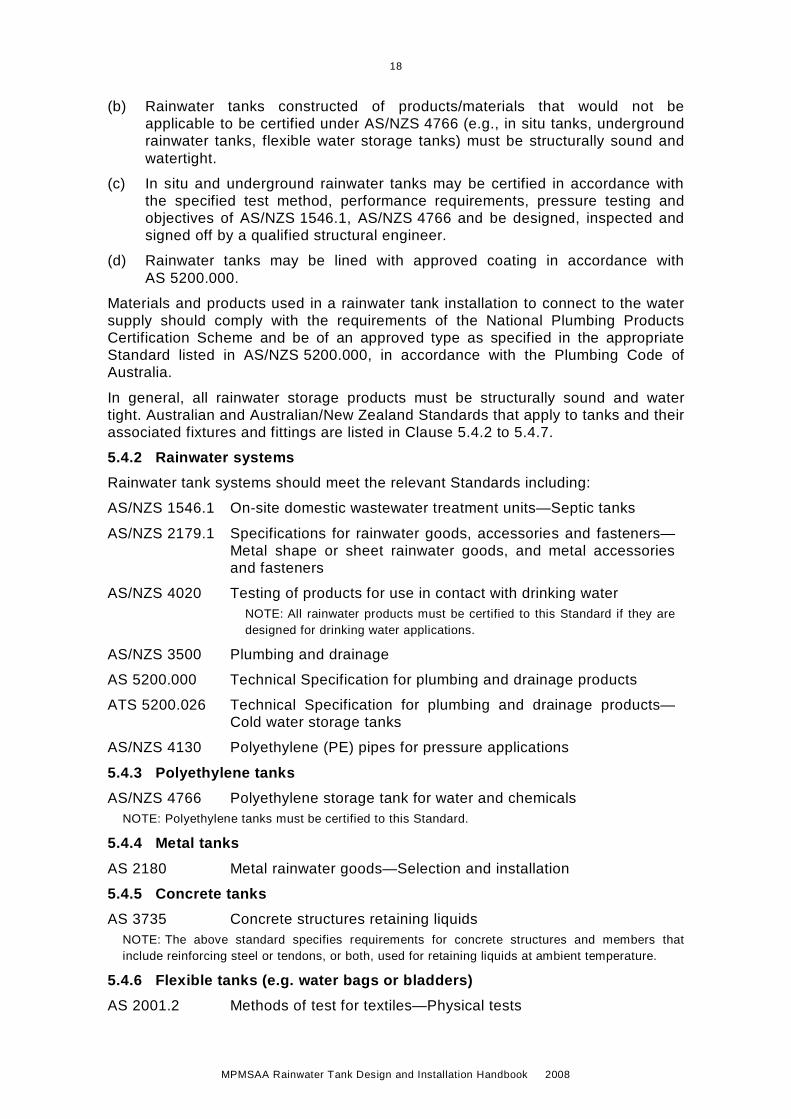
(b) Rainwater tanks constructed of products/materials that would not be applicable to be certified under AS/NZS 4766 (e.g., in situ tanks, underground rainwater tanks, flexible water storage tanks) must be structurally sound and watertight.
(c) In situ and underground rainwater tanks may be certified in accordance with the specified test method, performance requirements, pressure testing and objectives of AS/NZS 1546.1, AS/NZS 4766 and be designed, inspected and signed off by a qualified structural engineer.
(d) Rainwater tanks may be lined with approved coating in accordance with AS 5200.000.
Materials and products used in a rainwater tank installation to connect to the water supply should comply with the requirements of the National Plumbing Products Certification Scheme and be of an approved type as specified in the appropriate Standard listed in AS/NZS 5200.000, in accordance with the Plumbing Code of Australia.
In general, all rainwater storage products must be structurally sound and water tight. Australian and Australian/New Zealand Standards that apply to tanks and their associated fixtures and fittings are listed in Clause 5.4.2 to 5.4.7.
5.4.2 Rainwater systems
Rainwater tank systems should meet the relevant Standards including:
AS/NZS 1546.1 On-site domestic wastewater treatment units—Septic tanks
AS/NZS 2179.1 Specifications for rainwater goods, accessories and fasteners—Metal shape or sheet rainwater goods, and metal accessories and fasteners
AS/NZS 4020 Testing of products for use in contact with drinking water
NOTE: All rainwater products must be certified to this Standard if they are designed for drinking water applications.
AS/NZS 3500 Plumbing and drainage
AS 5200.000 Technical Specification for plumbing and drainage products
ATS 5200.026 Technical Specification for plumbing and drainage products—Cold water storage tanks
AS/NZS 4130 Polyethylene (PE) pipes for pressure applications
5.4.3 Polyethylene tanks
AS/NZS 4766 Polyethylene storage tank for water and chemicals NOTE: Polyethylene tanks must be certified to this Standard.
5.4.4 Metal tanks
AS 2180 Metal rainwater goods—Selection and installation
5.4.5 Concrete tanks
AS 3735 Concrete structures retaining liquids NOTE: The above standard specifies requirements for concrete structures and members that include reinforcing steel or tendons, or both, used for retaining liquids at ambient temperature.
5.4.6 Flexible tanks (e.g. water bags or bladders)
AS 2001.2 Methods of test for textiles—Physical tests

19
MPMSAA Rainwater Tank Design and Installation Handbook 2008
5.4.7 Other materials
Other materials will need to comply with relevant standards listed in Clause 5.4.1.
5.5 RAINWATER TANK SIZING
Many State and Local Governments mandate a minimum size of rainwater storage tank for new buildings and only certain sizes are eligible for many government rebate and incentive schemes (Chapter 11). Check with the local plumbing/building authority for any rainwater storage tank sizing requirements.
The following factors should be considered in determining the size of the rainwater tank for the intended use:
(a) Rainwater performance—Percentage yield of water supply expected to be sourced from rainwater.
(b) Rainfall for the region—Rainfall data from Bureau of Meteorology, local rainfall stations and responsible regulatory authority information.
(c) Roof catchment size—Square metres of specific roof catchment area discharging to tank.
(d) Allotment size—Available land to place tank in or on, the footprint size of the tank.
(e) Mains water—Is the network utility operator’s water supply available?
(f) Water demand—Intended use, daily water usage and consumption (an internal connection will allow better use of rainwater all year round).
(g) Stormwater detention—To be incorporated as part of the rainwater system.
TABLE 5.1
INDICATIVE VOLUMES OF WATER COLLECTED IN RAINWATER TANKS IN AUSTRALIAN CAPITAL CITIES
Annual rainfall (mm)
Roof area (m2)
100 150 200 250 300 400 500
Potential volumes of rainfall per year (kL)
150 10 15 20 25 30 40 50
200 14 21 28 35 42 56 70
250 18 27 36 45 54 72 90
300 22 33 44 55 66 88 110
400 30 45 60 75 90 120 150
500 38 57 76 95 114 152 190
600 46 69 92 115 138 184 230
800 62 93 124 155 186 248 310
1,000 78 117 156 195 234 312 390
1,200 94 141 188 235 282 376 470
(Source: enHealth 2004)
NOTE: See Chapter 12 for major cities rainfall. 1 KL = 1,000 L.

20
MPMSAA Rainwater Tank Design and Installation Handbook 2008
TABLE 5.2
ESTIMATES OF RAINWATER TANK YIELD FOR AUSTRALIAN CITIES
Tank size 2 kL 5 kL 10 kL
Roof area 50 m2 100 m2 50 m2 100 m2 50 m2 100 m2
Indoor and outdoor use
Brisbane 35 68 41 99 44 124
Sydney 40 77 47 105 50 128
Melbourne 24 68 24 86 24 98
Adelaide 22 57 22 73 22 82
Perth 29 58 30 74 30 84
Indoor use only
Brisbane 28 49 37 79 42 100
Sydney 22 35 31 50 38 59
Melbourne 18 36 23 52 24 63
Adelaide 16 32 19 47 22 56
Perth 15 28 19 40 24 48
(Source: The cost-effectiveness of rainwater tanks in urban Australia (2007). Assumes usage based on 2.4 occupants)
NOTES: 1 The above figures are based on daily time step data from the Bureau of Meteorology sites
(typically the airport). Substantial variation across cities may exist. Yield modelling errs toward a high estimate of yield by assuming that daily usage is drawn from run-off before it is drawn from tank balance.
2 Yields for large families may be higher due to higher use; yields may be lower if toilet, laundry or hot water systems are not connected to tank. The volume of rainwater required should be matched with tank size, roof area and uses.
3 See Chapter 12 for major cities rainfall.
5.6 RAINWATER TANK OPENINGS
Rainwater tanks require openings for roofwater to enter the storage tank, and openings for access of pumps, plumbing pipes and on going maintenance and cleaning activities.
The following criteria apply to rainwater tank openings:
(a) All rigid and flexible tank openings must be secured to prevent inappropriate entry of humans (e.g. children, animals, insects, surface water, ground water and rubbish).
(b) Be sealed to prevent surface water, groundwater entering the tank.
(c) If access lids are non-watertight be sealed or terminate a minimum 150 mm above finished ground level storm water flows, with the ground sloped away from the tank access lid.
(d) If access lids are watertight they are permitted to be flush with the finished surface level.
(e) Include insect and vermin control (includes mosquito prevention with 1.6 mm or less in Australian Guideline for Water Recycling 2B; other states may require 1 mm or less—Clause 9.4).
(f) Allow tank access.

21
MPMSAA Rainwater Tank Design and Installation Handbook 2008
(g) Prevent light penetration to reduce potential algae growth.
5.7 ABOVE-GROUND TANKS/TANK STANDS
Under the BCA, a rainwater tank is a Class 10b structure and height restrictions and setbacks apply—consult the responsible regulatory authority for building requirements. Tank stands should be engineered as required.
Weight of water 1000 L = 1 metric tonne of weight
5.8 GRAVITY FEED RAINWATER SYSTEMS
Every 1 m of height is 10 kPa of pressure (AS/NZS 3500.1 specifies that the most disadvantaged fixture in building requires 50 kPa). Low pressure inlet valves are available for toilet and washing machine systems; however, they may affect appliance fill times.
Stormwater drainagepipework
Finished sur face levelFSL
FSL
WC3 m
1 m FSL
Stop tap ( isolation valve)
Pre-storage f i lterand insect/vermincontrol
Stormwater over f lowto approved stormwaterdischarge point
FIGURE 5.1 WATER TANK AND PRESSURE SUPPLIED WITH GRAVITY FEED SYSTEM. MIN. PRESSURE IS 3 – 1 m = 20 kPa
(NOT CONSIDERING FRICTION LOSSES)

22
MPMSAA Rainwater Tank Design and Installation Handbook 2008
Stop tap ( isolation valve)
Rainwater pipework
Mains water supply
Max. f i l l leve l
Internal over f low
Cistern isolat ingvalve - potable water
Cistern isolat ingvalve - ra inwater
Toi let c istern
Rainwatersupply
Mains watersupply
Min. a i rgap 25 mm
NOTE: Rainwater feed pipe should have a suitable backflow prevention device to prevent water supply flowing into the rainwater tank and an appropriate backflow prevention device should be installed on mains water to protect this water supply (AS/NZ 3500—2003 Amendment No. 1, 2005).
FIGURE 5.2 INSTALLATION OF TOILET CISTERN WITH DUAL WATER SUPPLIES (MAIN AND RAINWATER)
5.9 STORMWATER PIPES AND FITTINGS
Currently, stormwater materials and products do not require authorization certification, but must be of suitable standard for their intended uses.
5.9.1 Stormwater drainage
All stormwater designs and installations must be in accordance with AS/NZS 3500.3, unless otherwise approved by the responsible regulatory authority. This Handbook specifies acceptable solutions for materials and products, design and installation of roof drainage systems, surface drainage systems and subsoil drainage systems to the point(s) of connection to the external stormwater drainage network.
5.9.2 Storm water drainage
All rainwater and stormwater pipe sizes must be in accordance with AS/NZS 3500.1 and AS/NZS 3500.3.
5.9.3 Roof drainage
The following apply to roof drainage systems:
(a) All roof drainage systems must be designed and installed in accordance with AS/NZS 3500.3 unless otherwise approved by the responsible regulatory authority (e.g. council).
(b) It is preferable that the minimum fall on eaves gutters be no flatter than 1:500 (0.2%) and for box gutters and internal guttering be no flatter than 1:200 (0.5%). Flat eaves gutters are permitted by AS/NZS 3500.3.
(c) Gutters to be one continuous length with no joints. Where this is not practicable, lap joints are to be in the direction of flow to the nearest downpipe. In many cases, manufactured gutters have specific joint bracket—refer to manufacturer’s installation requirements.

23
MPMSAA Rainwater Tank Design and Installation Handbook 2008
(d) Consideration should be given to the type of gutter fixing brackets to prevent the restriction of water flow, potential for build-up of debris, blockages and maintenance issues.
(e) Roof drainage should be designed to ensure that the rainwater tank roof catchment area is falling towards the rainwater tank location and appropriate number of downpipes have been allocated and positioned appropriately.
(f) Downpipes discharging to the rainwater tank for wet systems (water charged) should have a minimum 100 mm vertical distance between the rainwater head and the tank inlet. The rainwater head should be leaf screened and vermin and insect proofed (including mosquito screening). The stormwater system should be designed with the provision to drain stagnate water during dry weather periods (e.g. capped relief access point at lowest level of stormwater drainage system).
(g) Lead flashing for roofing cannot be used on new buildings [see Building Code of Australia (BCA)].
5.9.4 Rainwater tank overflow—Point of discharge
The following apply to the point of discharge of rainwater tank overflow:
(a) Rainwater tank placement and tank overflow is to be designed to ensure stormwater does not pond under building floors or flood around foundations of buildings. Excess moisture around buildings could provide potential risk of rotting timber, corroding metal fittings and reinforcement in concrete slabs, and in clay soils may lead to cracking of house walls or retaining walls.
(b) The tank overflow may be connected to the existing stormwater system or kerb and channel, or inter-allotment stormwater pit. The water from the overflow is still considered to be stormwater and the requirements of AS/NZS 3500.3 apply.
(c) Either a physical air break or other backflow prevention device such as reflux valve on the outlet from the tank overflow is required before connecting to the stormwater drainage system.
(d) If no stormwater system exists and the property falls away from the street, the tank overflow may have to be drained to an on-site stormwater dispersion system. The local responsible regulatory authority must approve on-site stormwater dispersion systems before installation.
(e) All plumbing stormwater connections to comply with the responsible regulatory authority requirements.
5.9.5 Siphonic roof drainage systems (commercial buildings)
Siphonic roof drainage systems are vertical and horizontal pipes designed to fill on a rain event to create a negative atmospheric pressure (vacuum), causing a siphonic action in the system; drawing large volumes of water to drain off the roof at a rapid rate. Refer to hydraulic consultant and manufacturer’s specification for system design.
5.10 RAINWATER SERVICE PIPE FROM RAINWATER TANK
5.10.1 General
The rainwater service pipe connected from a rainwater tank to the plumbing fixtures/fittings should comply with AS/NZS 3500.1 (see Chapter 7, Rainwater labelling and marking).

24
MPMSAA Rainwater Tank Design and Installation Handbook 2008
5.11 RAINWATER TANK CONNECTION DEVICES IN CONTACT WITH THE NETWORK UTILITY DRINKING WATER
5.11.1 General
Connection devices in contact with network utility water supply should comply with the standards listed in AS 5200.000. It is the responsibility of designers, manufacturers, suppliers and installers to verify the suitability of products for their specific application. These products should clearly show product certification, such as set out in the following documents:
• ATS 5200.466—2004, Technical Specification for plumbing and drainage products—Rainwater tank connection devices
• ATS 5200.467—2004, Technical Specification for plumbing and drainage products Rainwater tank connection valve
5.11.2 Devices for control of rainwater and water utilities supply connections
Devices for the connection of rainwater and the network utility operator’s water supply pipework, valves or devices should have WaterMark certification in accordance with the Standards listed in AS 5200.000, or authorization under the Plumbing Code of Australia. If rainwater is plumbed internally and connected with mains water supply, the rainwater connection devices need to meet WaterMark standards (www.standards.org.au).
5.11.3 Tank top-up device
Also known as an ‘air gap or air break system’ a tank top-up device should maintain a minimum water level within the rainwater storage tank. If there is insufficient rainwater available, this minimum level is topped up with mains water. A pump pressurises the water to supply the demand to the connected appliances.
This system always requires electricity. Water restrictions may also apply to the stored water (check State/Territory regulations).
5.11.4 Interconnect device
Interconnect device(s) automatically select between two alternate water source—rainwater or mains water. A pump is used to pressurise the water to supply the demand to the connected appliances. If there is insufficient rainwater storage or a power outage the system reverts to mains water supply. Systems that are designed as mains priority systems may still supply water in the event of pump failure or a dripping tap—although they may save on energy consumption they do not maximise the use of rainwater.
5.12 RAINWATER TANK CONNECTED TO SINGLE SOURCE PUMP
The provision of a pump connected to the rainwater source may assist with the availability of stronger pressure for the purpose of garden irrigation via the connection to a hose, sprinkler or drip irrigation.
The most basic pump systems are manually operated at the power switch, whilst more sophisticated systems have automatic stop/start functionality and ‘run dry’ protection for the pump should there be insufficient rainwater. The pump may be a surface mount pump or submersible pump type. Refer to Chapter 6 for further recommendations for pumps.

25
MPMSAA Rainwater Tank Design and Installation Handbook 2008
5.13 FLEXIBLE RAINWATER TANKS
The following criteria will need to be adhered to when installing flexible water tanks:
(a) Flexible storage tanks manufactured from non-reinforced material must include a containment structure, or similar, to protect the storage tank from contact with building structures.
(b) All rainwater draining to the flexible storage tank must pass through appropriate debris screening or filtering mechanisms to prevent the debris from entering the flexible tank.
(c) All rainwater downpipes draining to the flexible storage tank must be designed to avoid cross-connection between the drainage to the flexible tank and the overflow to stormwater. The overflow pipework must allow the unrestricted flow of water to stormwater once the flexible storage tank has filled.
(d) The installation site must be level and free of debris or anything that might damage the flexible tank. Flexible storage tanks must be installed in such a way that they will be clear of any building structure at all times.
(e) There must be no more than two downpipes per each overflow point. If insufficient overflow points are available, then a relief point must be installed to prevent flexible tanks from overfilling in a significant rainfall event.
(f) The height of the invert of the overflow to stormwater must be no higher than the maximum fill height of the flexible storage tank, unless it is designed to hold pressure and not expand beyond a predetermined size as specified by the manufacturer.
(g) All flexible storage tanks should have a relief flap beyond the point of the overflow to allow the release of water and/or debris, if for some reason the stormwater overflow to the street becomes blocked.
(h) All flexible storage tank seams must be tested in accordance with AS 2001.2.20.
5.14 ON-GROUND, IN-SLAB RAINWATER STORAGE TANKS
On-ground, in-slab rainwater storage tanks should be planned in conjunction with structural engineers, footing layout and site classification. Edge beam design and reinforcing bar position may need specific application (see AS 2870).
Additional action will be required to filter rainwater and protect slab tanks from sediment build up.
The rainwater storage tank should be placed as normal waffle pods above the plastic membrane vapour barrier (see Figure 15.16). The stormwater overflow connection and backflow protection from it should be above finished ground level and include means for vermin and insect control (including mosquito control).
5.15 UNDERGROUND RAINWATER TANKS
Underground rainwater tanks (e.g. Clause 16.2) must comply with following guidelines:
(a) The overflow to stormwater must be designed to stop any surcharge from the stormwater from entering the underground rainwater tank.
(b) Tank access lids are to be designed and installed to prevent child access and stormwater ingress.

26
MPMSAA Rainwater Tank Design and Installation Handbook 2008
(c) All underground tanks in water charged areas must be designed and installed to prevent hydrostatic uplift (so as not to lift or move out of the ground) (Figure 5.3).
(d) For backflow prevention requirements refer to AS/NZS 3500.1 and/or the regulatory authority having jurisdiction (Chapter 8).
(e) All underground stormwater drainage systems should be designed and installed in accordance with AS/NZS 3500.3, unless otherwise approved by the responsible regulatory authority.
(f) Site selection considerations should include:
(i) Area of influence
(ii) Existing services and buildings (foundations)
(iii) Boundaries
(iv) Stormwater drainage
(v) Tree roots
(vi) Soil classification
(vii) Flood, stormwater (surface water) and tidal zones
(viii) Ground water
(g) Maintenance program—refer to manufacturer’s recommendations.
Underground geo-fabric cell structure stormwater systems are not covered in this Handbook. This Handbook only covers rainwater/roofwater systems.
Considerations to be included for calculation of hydrostatic lift in underground storage tanks are given in Figure 5.3.
5.16 HYDROSTATIC LIFT—BALLAST CALCULATIONS
Buried tanks may have a tendency to move (float) when empty, especially if the ground is water charged. To avoid floating, the total weight of the tank, overburden (the backfill above the tank) or an engineered design must provide resistance to counterbalance the buoyancy of the tank (hydrostatic lift). The ballast needs to be greater than the volume of the tank (e.g. a 5000 L tank requires approximately 5000 kg (5 tonne) of ballast when empty).
A consulting engineer may be used to design a more efficient solution based on the specific site conditions and backfill material. These calculations are only required if not specified by the manufacturer, or if installation be as per manufacturer’s instructions. If tanks are installed underground, check manufacturer’s detailed installation instructions.
The following provides a simplified method to calculate ballast.
The installation site assumptions include the following:
(a) The groundwater level at the finished surface level (FSL).
(b) There are no side frictional forces as the water-charged ground acts as a lubricant.
(c) Physical constants that can be use in calculations:
(i) Weight (mass) of water = 1000 kg/m3 (1000 L = 1000 kg) (m3 = cubic metres).
(ii) Weight (mass) of concrete if used (in air) = 2400 kg/m3.

27
MPMSAA Rainwater Tank Design and Installation Handbook 2008
(iii) Weight (mass) of alternative backfill = Dependent on backfill material and moisture content (e.g. saturated crushed rock is 2120 kg/m3).
(iv) Weight (mass) of tank = as per manufacturer’s specifications.
Sufficient mass or resistance is needed to counterbalance the buoyancy of the tank void:
(i) Determine the buoyant force exerted on the tank. The buoyant force is the weight of the displaced water or weight of the water when the tank is full (Vt) (i.e. the volume of tank, units = L ≈ kg).
(ii) From the manufacturers technical information determine the weight (mass) of the tank (Wt) (units = kg).
(iii) Determine the approximate weight of the overburden required (A1 × A2 × D0 × 2120, units = kg. where A1, A2 and D0 are measured in metres). The overburden plus the weight of the empty tank (Wt) must be equal or greater than Vt. If this can not be achieved, a structural engineer will be for the design.
Many tank designs incorporate ways to counteract hydrostatic lift through the design and installation process (refer to manufacturer’s or structural engineer’s installation requirements).
FSL
45o
Angle of repose
Buildingfoundationfootings
Tank
Finished sur face levelFSL
D0
A 1
A 2
A 2
H
Wt
3
Overburden
Overburden
Backfi l l tomanufacturer’srecommendation
Tank volume mV t
Backfi l l material,refer to manufacturer’srecommendations
Optional concrete support ballast,refer to manufacturer’srecommendations
Traf f icable area
Optional soil /backfi l l
NOTE: All underground storage tanks should be engineered as required.
FIGURE 5.3 CONSIDERATIONS TO BE INCLUDED FOR CALCULATION OF HYDROSTATIC LIFT—BALLAST FOR UNDERGROUND STORAGE TANKS

28
MPMSAA Rainwater Tank Design and Installation Handbook 2008
C H A P T E R 6 P R E S S U R E A N D P U M P S
6.1 GENERAL
The addition of a pump to a rainwater harvesting system will increase the range of uses for the collected rainwater. Modern appliances and irrigation systems need pressurised water to operate efficiently.
In accordance with AS/NZS 3500.1, the maximum static pressure at any outlet, other than a fire service outlet, within a building is not to exceed 500 kPa. Possible locations of pressure limiting valve, depending on site constraints, are front boundary downstream of water meter or before entering the building. The pressure limiting valve should be accessible for maintenance purposes.
Minimum pressure at the most disadvantaged plumbing fixture or outlet should not be less than 50 kPa at the minimum flow rate required (refer to AS/NZS 3500.1.).
6.2 PUMP SELECTION CRITERIA
To determine the appropriate pump for your rainwater tank system the following should be considered:
(a) Is the rainwater tank located above-ground or below-ground level?
(b) Is the pump to be installed in the tank or near the rainwater tank?
(c) Number of plumbing fixtures and flow rates to be served by rainwater supply.
(d) Number of people living in the house—to determine the probable simultaneous flow rate for the building.
(e) Is the building a single- or double-storey residence? Height from rainwater tank pump to most disadvantaged fixture outlet.
(f) Residual head of the most disadvantage plumbing fixture.
(g) Pressure drop and index length of the rainwater system (refer to AS 3500.1).
(h) Pump should have a safety device to prevent pump running dry.
(i) Select a pump that is efficient for intended use, do not over- or under-size the pump, consider energy efficiency and electrical power consumption.
(j) Control device (e.g. pressure control)—to start and stop the pump automatically, depending upon water usage demand.
(k) The pressure of the water supply in a gravity feed system is 10 kPa for every 1 m of head.
(l) Proximity to electrical supply.
Once you have all this information, consult your plumber, construction hydraulic designer and/or pump supplier to determine the most appropriate pump for your intended use.
6.3 PUMP NOISE
Pump operating noise levels are measured in decibels (dB) and this information should be included on the pump data labels. All rainwater tank pumps must be installed so as noise levels from any pump do not create a nuisance to occupants and/or any neighbouring properties (refer to local authority guidelines).

29
MPMSAA Rainwater Tank Design and Installation Handbook 2008
To reduce the potential noise concerns from rainwater tank pumps in urban areas, the following provisions may be used to address the noise issue:
(a) Installation a submersible rainwater pressure pump.
(b) Installing solid fence, lapped fence palings.
(c) Installing the pump inside a purpose-built pump box (pump cover) with adequate ventilation to prevent the pump from overheating when operating. (Ask for advice from the pump manufacturer and/or installer.)
(d) Locate pump as far away as possible from neighbours and away from sensitive areas (e.g. bedroom windows). (Refer to the responsible regulatory authority requirements.)
(e) Avoid placing the pump near a noise-reflective surface (e.g. alcoves, walls).
(f) Install pump on a vibration pad.
(g) Ensure all pipework is secured.
(h) Where noise may be an issue, selection of type of pipe, pipework design and acoustic wrapping should be considered.
The provisions listed above will assist in compliance with the noise emission criteria; however, they are not to be considered as the only measures to be incorporated.
6.4 PUMP PROJECTION INSTALLATION
To maximise the operating life of a rainwater pump, it will need to be protected from water, UV light, dust and extremes of temperature.
External pumps should ideally be installed:
(a) onto a firm base such as a concrete pad, so that vibrations do not cause pump movement and increased stress on pipework;
(b) in a free-draining area that is not prone to flooding;
(c) with isolating valves and barrel unions for ease of service;
(d) so water cannot freeze inside the pump or associated pipework (if in a frost-prone area);
(e) so they are not exposed to long periods of sunlight—consider the southern side of buildings;
(f) under cover to eliminate rainfall and dew build-up on the pump’s electrical components;
(g) in a well-ventilated area so that waste motor heat is circulated away from the motor;
(h) so that flammable materials are not stored near or on the pump; and
(i) to ensure primed pumps do not loss prime water (refer to manufacturer’s instructions).

30
MPMSAA Rainwater Tank Design and Installation Handbook 2008
6.5 PUMP PERFORMANCE
Typical rainwater pumps offer maximum pressure at low flows and maximum flow at low pressures, with a mid point usually their most efficient or best efficiency point (BEP). It is considered important to provide suitable water pressure for internal connections and irrigation systems for effective appliance usage. Pump performance should be tested in compliance with AS/NZS 2417.2001 minimum grade 2 requirements, electrical safety standards (AS/NZS 60335.2.41) and electromagnetic compatibility (AS/NZS CISPR14.1).
Pump and appliance performance can be maximised by the following measures:
(a) Selecting appropriate pump as per Clause 7.1—Pump selection criteria.
(b) Ensuring the most appropriate pipe types and diameters are chosen in relation to pressure and flow rates.
(c) Ensuring pump is primed and there are no leaks in the suction or discharge pipe(s).
(d) Keeping the pump as close as possible to the rainwater tank to minimise the suction lift.
(e) High quality rain water entering and being stored in the tank (relates to pump life). For improving the quality of harvested rainwater - refer to Chapter 10 – Management of Rainwater Quality.
(f) Limiting the number of fittings in the pipework that may cause friction losses, such as valves, elbows and filters.
(g) Ensuring filters and strainers are cleaned regularly—the cleaning intervals are determined by the cleanliness of the rainwater.
(h) Selecting a pump that closely matches the duty point that best suits the application. Consult the pump supplier.
(i) Installing a floating pump intake to allow clean water into pump inlet.
6.6 MINIMUM AND MAXIMUM FLOW RATES AND PRESSURE REQUIREMENTS
Many State and Local Governments are now adopting minimum and maximum flow rates for domestic household fixtures and tapware.
Table 6.1 sets out an example of flow rate requirements. Please refer to the responsible regulatory authority and AS/NZS 3500.1.

31
MPMSAA Rainwater Tank Design and Installation Handbook 2008
TABLE 6.1
MINIMUM AND MAXIMUM FLOW RATES AND RECOMMENDED PRESSURES FOR PLUMBING FIXTURES
Plumbing fixture Minimum flow rates (L/min.)
Maximum flow rates (L/min.)
Recommended minimum pressure****
(kPa)
Basin* 6 9 50
LSll bath* 18 18 50
Dishwasher* 12 12 200
Hose tap—15 mm 12 12 50
Hose tap—20 mm 18 18 50
Kitchen sink* 7 9 50
Laundry tub 7 9 50
Shower* 6 9 200
Urinal flushing control* Mechanisms: litres/single stall, litres/600 mm width of multiple stall
2*** 2*** 50
Washing machine* 12 12 100
Water closet* (toilet) 6 6 50
Hot water MR MR 200
Cooling towers MR MR 200
Low flush valves MR MR 30
Tempering valves MR MR 200
Mains pressure flush valves MR MR 350
Thermostatic valves MR MR 200
Irrigation MR MR 100-400**
LEGEND: MR Check manufacturer’s requirements * Tapware and water using appliances covered by the WELS Act 2005 must be labelled with
the water efficiency ‘star rating’ in accordance with AS/NZS 6400 ** Dependent on the irrigation system requirements, refer to manufacturer/designer *** Smart-demand operation serving a single stall **** These are minimums; see manufacturers information for maximum pressures, all fixtures
should be limited to 500 kPa to comply with AS/NZ 3500. Check specified requirements for products before installation

32
MPMSAA Rainwater Tank Design and Installation Handbook 2008
C H A P T E R 7 R A I N W A T E R M A R K I N G A N D L A B E L L I N G
7.1 GENERAL
The water supply systems (including irrigation) from a rainwater tank must be clearly marked with the contrasting coloured (white text on a green background) wording ‘RAINWATER’ in accordance with AS/NZS 3500.1.
7.2 PIPE MARKINGS
Pipework less than 40 mm (DN 40) in diameter should have a continuous green pipe marker band (Code Tape) around the circumference of the pipe with the word ‘RAINWATER’ in not less than 4 mm upper-case letters placed longitudinally along the pipe and repeated several times around the circumference so that they are visible from all viewing directions (see Figure 7.1).
FIGURE 7.1 CONTINUOUS GREEN PIPE MARKER FOR PIPEWORK LESS THAN 40 MM DIAMETER (USED TO IDENTIFY RAINWATER PIPEWORK)
Pipe markers are to be used to identify all rainwater pipework (accessible and non-accessible).
For all above- and below-ground non-accessible rainwater pipework (e.g. plumbing rough-ins), the pipe markers (Figure 7.1) are to be placed on the pipe at intervals not exceeding 0.5 m in length with the word ‘RAINWATER’ in contrasting colour and should comply with AS 1345.
For all rainwater pipework installed in accessible locations (e.g. car park basements), the pipe markers are to be placed on the pipe at intervals not exceeding 3 m in length and adjacent to branches, valves, wall and floor penetrations. Identification markings should comply with AS 1345.
Green pipe may also be used to indicate rainwater. These must also be marked with ‘RAINWATER’ at intervals not exceeding 0.5 m for non-accessible pipe and intervals less than 3 m for accessible pipe.
7.3 IRRIGATION PIPE
Irrigation systems past the point of mains or rainwater water supply are unregulated plumbing and not considered within the AS/NZS 3500 series.
� RAINWATER � � RAINWATER � � RAINWATER � � RAINWATER � � RAINWATER �

33
MPMSAA Rainwater Tank Design and Installation Handbook 2008
7.4 EXTERNAL TAP SIGNAGE
Rainwater outlets should be identified as ‘RAINWATER’ with a label or a rainwater tap identified by a green coloured indicator. Rainwater warning signs should comply with AS 1319 (see Figure 7.2).
����� �������
FIGURE 7.2 EXAMPLE OF TYPICAL RAINWATER SIGNAGE

34
MPMSAA Rainwater Tank Design and Installation Handbook 2008
C H A P T E R 8 B A C K F L O W P R E V E N T I O N
8.1 GENERAL
Backflow prevention must comply with the installation requirements of AS/NZS 3500.1. Where backflow prevention is not provided by the water supply network utility operator, the authority having jurisdiction may require water containment protection at the property boundary to be installed in addition to that required by AS/NZS 3500.1.
Table 8.1 provides an indication of backflow prevention required for rainwater tank installations where the tank installed is completely watertight and the tank and fittings do not allow ingress of water from any other source apart from the rainwater harvesting area.
Under the performance provisions of the Plumbing Code of Australia, rainwater systems designed and certified by an appropriately qualified person may be accepted by the authority having jurisdiction with lesser backflow protection provision. The following must be considered in making the submission:
(a) Rainwater tank design and performance.
(b) Surrounding hazards (sewered/non-sewered areas).
(c) Installation of pipework, openings and other fittings.
TABLE 8.1
BACKFLOW PREVENTION MINIMUM REQUIREMENTS FOR ZONE PROTECTION TANK INSTALLATIONS IN URBAN AREAS
Rainwater tank location
Protection on supply line prior to tank for provision of top-up
Protection on the main supply line prior to connection to
tank outlet line
No top-up or connection to rainwater tank
Buried Testable device Testable device No backflow prevention device required
Partly buried Non-testable device Testable device
Above-ground Non-testable device Non-testable device
NOTE: The selection of a backflow prevention device should be determined based on the level of hazard in the immediate environment (see Table 8.2) in consultation with the local water authority.

35
MPMSAA Rainwater Tank Design and Installation Handbook 2008
TABLE 8.2
SUITABILITY OF BACKFLOW PREVENTION DEVICE
Examples of back flow prevention are indicated on Figure 8.1 (i.e. air gap and dual check valve). Check requirements with the local responsible authority.
Registered or testable backflow prevention device
Cross-connection hazard rating
Protection against back-
pressure
Protection against back-
siphonage
(a) Registered testable devices
Registered break tank (RBT) High/medium/low Yes Yes
Registered air gap (RAG) High/medium/low Yes Yes
Reduced pressure zone device (RPDA)*
High/medium/low Yes Yes
Double-check valve assembly (DCV)*
Medium/low Yes Yes
Double-check detector assembly (DCDA)*
Medium/low Yes Yes
Anti-spill pressure tyre vacuum breakers (APVB)*
High/medium/low † No Yes
Pressure type vacuum breaker (PVB)*
Medium/low No Yes
(b) Non–testable devices
Dual-check valve with atmospheric port (DVAP) ‡
Low Yes Yes
Dual-check valve (DUAL CV) ‡ Low Yes Yes
Dual-check valve with intermediate vent (DuCV) ‡
Low Yes Yes
Air gap (AG) Low Yes Yes
Break tank (BT) Low No Yes
Atmospheric vacuum breaker (AVB) ‡
Low No Yes
Hose connection vacuum breaker (HCVB) ‡
Low No Yes
Beverage dispenser dual-check valve (BDDC)
Low Yes Yes
Vacuum break-check valve (VBCV)
Low No Yes
Single-check valve (in Australia only)
Fire services only
(Source: Table 4.1 AS/NZS 3500.1:2003)
* Backflow prevention devices that are provided with test taps for the purposes of testing the operation of the devices, which do not necessarily include isolating valves
† Anti-spill vacuum breakers are suitable for high-hazard installation for mains pressure flushing valves only
‡ Backflow prevention devices that are not provided with test taps for the purposes of testing the operation of the devices
36
MPMSAA Rainwater Tank Design and Installation Handbook 2008
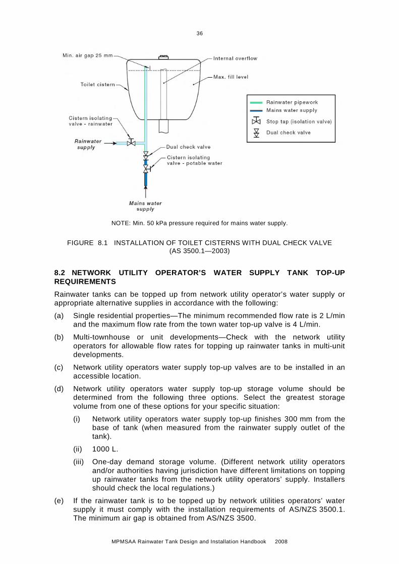
NOTE: Min. 50 kPa pressure required for mains water supply.
FIGURE 8.1 INSTALLATION OF TOILET CISTERNS WITH DUAL CHECK VALVE (AS 3500.1—2003)
8.2 NETWORK UTILITY OPERATOR’S WATER SUPPLY TANK TOP-UP REQUIREMENTS
Rainwater tanks can be topped up from network utility operator’s water supply or appropriate alternative supplies in accordance with the following:
(a) Single residential properties—The minimum recommended flow rate is 2 L/min and the maximum flow rate from the town water top-up valve is 4 L/min.
(b) Multi-townhouse or unit developments—Check with the network utility operators for allowable flow rates for topping up rainwater tanks in multi-unit developments.
(c) Network utility operators water supply top-up valves are to be installed in an accessible location.
(d) Network utility operators water supply top-up storage volume should be determined from the following three options. Select the greatest storage volume from one of these options for your specific situation:
(i) Network utility operators water supply top-up finishes 300 mm from the base of tank (when measured from the rainwater supply outlet of the tank).
(ii) 1000 L.
(iii) One-day demand storage volume. (Different network utility operators and/or authorities having jurisdiction have different limitations on topping up rainwater tanks from the network utility operators’ supply. Installers should check the local regulations.)
(e) If the rainwater tank is to be topped up by network utilities operators’ water supply it must comply with the installation requirements of AS/NZS 3500.1. The minimum air gap is obtained from AS/NZS 3500.

37
MPMSAA Rainwater Tank Design and Installation Handbook 2008
(f) Connection between service pipes should comply with the installation requirements of AS/NZS 3500.1, and should consider guidance in this Handbook.
(g) All rainwater control valves must have WaterMark compliance certification in accordance with PCA and AS/NZS 5200.000. The rainwater control valve should be appropriately sized for the intended use (such as pipework, fittings, backflow prevention device) and ensure the pressure, flow and velocity performance requirements are satisfied (see Figure 8.1).

38
MPMSAA Rainwater Tank Design and Installation Handbook 2008
C H A P T E R 9 M A N A G E M E N T O F R A I N W A T E R Q U A L I T Y
9.1 GENERAL
Rainwater catchment areas and their management can impact on the quality of rainwater (Clause 2.6). There are also a number of rainwater treatment devices available that can assist in cleaning and disinfecting rainwater, depending on the end use of the rainwater. If the end use is drinking or food preparation the water quality should comply with the Australian Drinking Water Guidelines. The Guidance Manual for the Design and Installation of Urban Roofwater Systems in Australia also provides information on the design and management of rainwater systems.
9.2 MINIMISING CONTAMINATION
Preventative measures to reduce contamination by potentially harmful micro organisms are reliant on minimising the impact of faecal waste. Measures should include the following (see also Table 9.1):
(a) Ensuring the roof is appropriate to capture rainfall from (e.g. no overhanging tree).
(b) Keeping roof catchments clear of overhanging vegetation, as branches provide roosting points for birds and can provide access for small animals such as rodents, cats and possums.
(c) Preventing access by small animals and birds into rainwater tanks by screening all tank inlets and overflows, keeping access hatches closed and by maintaining the integrity of tank roofs (see Clause 9.4).
(d) Preventing entry of surface run-off from areas other than the roof catchment into below-ground tanks. Roofs should be secure and the sides and bottom of tanks should be sealed to prevent ingress.
(e) Preventing swimming in storage tanks, as this type of human access can greatly increase the risk of contamination.
Preventative measures will also minimise the risk of contamination of rainwater from roof catchment or the rainwater system. Many of the hazards that require preventive measures and management are summarised in Table 9.1.
Before installing a rainwater tank for a single household the roof catchment should also be checked for other source of contamination:
(i) Overhanging vegetation—should be pruned.
(ii) A flue from a slow combustion heater—if possible this section of roof should be avoided; if not ensure the flue is installed in accord with Australian/New Zealand Standards.
(iii) Overflows/discharges/bleed-off pipes from roof-mounted appliances, such as evaporative air conditioners, hot water services, and solar heaters – should not discharge onto the rainwater catchment area.
(iv) Large amounts of uncoated lead flashing—should be painted.
(v) Exposed preservative-treated timber—should be sealed or the section of roof containing the timber should not be used for collection of rainwater.

39
MPMSAA Rainwater Tank Design and Installation Handbook 2008
Gutters should have sufficient and continuous fall to downpipes to prevent pooling of water, which could increase accumulation of material, lead to algal growth and possibly provide a site for mosquito breeding. A fall of 1:100 should be sufficient.
Gutter shielding devices will substantially reduce the amount of larger debris (bark, larger leaves, etc.) but small particles will not be removed. Periodic cleaning will still be needed but at a lower frequency than for gutters without shielding.
40
MPMSAA Rainwater Tank Design and Installation Handbook 2008
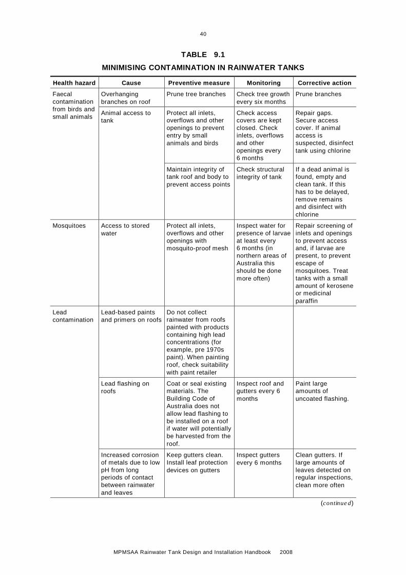
TABLE 9.1
MINIMISING CONTAMINATION IN RAINWATER TANKS
Health hazard Cause Preventive measure Monitoring Corrective action
Faecal contamination from birds and small animals
Overhanging branches on roof
Prune tree branches Check tree growth every six months
Prune branches
Animal access to tank
Protect all inlets, overflows and other openings to prevent entry by small animals and birds
Check access covers are kept closed. Check inlets, overflows and other openings every 6 months
Repair gaps. Secure access cover. If animal access is suspected, disinfect tank using chlorine
Maintain integrity of tank roof and body to prevent access points
Check structural integrity of tank
If a dead animal is found, empty and clean tank. If this has to be delayed, remove remains and disinfect with chlorine
Mosquitoes Access to stored water
Protect all inlets, overflows and other openings with mosquito-proof mesh
Inspect water for presence of larvae at least every 6 months (in northern areas of Australia this should be done more often)
Repair screening of inlets and openings to prevent access and, if larvae are present, to prevent escape of mosquitoes. Treat tanks with a small amount of kerosene or medicinal paraffin
Lead contamination
Lead-based paints and primers on roofs
Do not collect rainwater from roofs painted with products containing high lead concentrations (for example, pre 1970s paint). When painting roof, check suitability with paint retailer
Lead flashing on roofs
Coat or seal existing materials. The Building Code of Australia does not allow lead flashing to be installed on a roof if water will potentially be harvested from the roof.
Inspect roof and gutters every 6 months
Paint large amounts of uncoated flashing.
Increased corrosion of metals due to low pH from long periods of contact between rainwater and leaves
Keep gutters clean. Install leaf protection devices on gutters
Inspect gutters every 6 months
Clean gutters. If large amounts of leaves detected on regular inspections, clean more often
(continued)

41
MPMSAA Rainwater Tank Design and Installation Handbook 2008
Health hazard Cause Preventive measure Monitoring Corrective action
Airborne pollutants
Industry and vehicles
Do not collect rainwater if in a known high air pollution area, or ensure a first flush diverter is installed
Assess functionality of first flush diverter and pollution dust apparent on roofing material every 6 months. Check water quality for a range of commonly found airborne pollutants
Install and monitor first flush diverters
Sulphide/ rotten egg/ sewage odours
Anaerobic growth in accumulated sediment at the bottom of tanks
Regularly clean tank to remove accumulated sediment
Inspect tank every 2-3 years
Clean tank if required. If cleaning not practical (for example, in middle of summer) disinfect tank with chlorine and flush chlorinated water through all pipework
Slime and stagnant water in pipework
Avoid u-bends or underground pipework that can hold stagnant water. Install drainage points on pipework
Musty or vegetable type taste and odours (no light penetration)
Accumulated on roofs and gutters. Possibly including pollen
Remove overhanging branches from trees. Keep gutters clean. Install leaf protection devices on gutters
Inspect gutters at least every 6 months
Clean gutters. If large amounts of leaves (or pollen) are detected on regular inspections, clean more often
Coloured water
Accumulated damp leaves in gutter
Keep gutters clean. Install leaf protection devices on gutters
Inspect gutters at least every six months
Clean gutters. If large amounts of leave are detected on regular inspections, clean more often
Coloured water, particularly after rain (tiled roof)
Coloured coating from tiles washed into tanks. Re-suspension from sediments when fresh intake
Use colour-through tiles
Inspect water after rainfall
Remove sediment by cleaning the tank
(continued)
TABLE 9.1 (continued)

42
MPMSAA Rainwater Tank Design and Installation Handbook 2008
Health hazard Cause Preventive measure Monitoring Corrective action
Musty, vegetable or fishy type taste and odours (light penetration)
Algal growth due to light penetration into tank or pipework
Make sure tank is completely roofed and is impervious to light
Inspect water every six months
Repair roof
Ensure pipework, including inlets to tanks, are impervious to light (white pipes can allow light penetration)
Paint pipework with dark colour
Insects/water boatmen/bees etc.
Access to stored water
Protect all inlets, overflows and other openings with insect-proof mesh
Inspect water for presence of insects and/or larvae every six months
Repair screenings of inlets and openings to prevent further access. Use simple coarse filter to remove remaining insects
Small white flakes in water
Microbial growth Keep gutters clean. Growth encouraged by nutrients contained in plant and soil material accumulated in gutters or at the bottom of tanks.
Install leaf protection devices on gutters
Inspect gutters at least every six months.
Inspect tank every 2-3 years
Clean gutters and tank if necessary.
Disinfect tank using chlorine
Slime on the inside of tanks
Microbial growth All containers that continuously hold water will develop biofilms on surfaces below the water level
None required None required. These are naturally occurring and not harmful to the general population
(Information supplied by NSW EnHealth, see also The Guidance Manual for the Design and Installation of Urban Roofwater Systems in Australia.)
For a collection scheme from buildings larger than a single household, the Australian Guidelines for Water Recycling (Storm Water) indicate that before installing any rainwater system the roof should be inspected and ideally not have:
(A) copper roofing material;
(B) public access (roofs with maintenance access are acceptable);
(C) vehicular access;
(D) structures above the roof that may rust or corrode (e.g. unpainted metal or concrete) or provide a resting place for birds;
(E) discharge, overflow or bleed-off pipes from roof mounted appliances such as air conditioning units, hot water services and solar heaters;
(F) a flue from a slow combustion heater that is not installed in accordance with the relevant Australian Standard;
(G) a chimney or flue from an industrial process within the building;
(H) exposure to chemical sprays from processes within the building (e.g. spray painting) which may be deposited on the roof; or
TABLE 9.1 (continued)

43
MPMSAA Rainwater Tank Design and Installation Handbook 2008
(I) significant atmospheric deposition of pollutants (e.g. from industrial sources or from aerial spraying).
If a roof has these characteristics, roofwater quality monitoring for relevant contaminants should be carried and an assessment made of any associated health and environmental risks. Suggestions for further protecting roofwater quality for non-residential buildings include the roof not having:
(1) overhanging vegetation that may attract birds and drop debris onto the roof;
(2) bitumen-based materials or with lead-based paints;
(3) deteriorated asbestos roofing material;
(4) preservative treated wood; or
(5) lead flashing that is not painted/sealed.
9.3 PRE-STORAGE TREATMENT DEVICES
As the first rainfall may contain higher than average amounts of accumulated dust, industrial pollutants, bird and animal droppings, leaves and other debris it could be recommended that, to prevent the risk of potential contaminants adversely affecting rainwater quality and human health, the following measures may be implemented:
(a) Screened downpipe rainwater head or other suitable leaf and debris device should be installed on each downpipe. Recommended screen mesh to be 4–6 mm and designed to be self-cleaning.
(b) To improve rainwater quality a minimum 20 L per 100 m2 of the first flush of roof catchment should be diverted/discarded before entering the rainwater tank. Individual site analysis is required in heavy pollutant areas to determine if larger volumes of first flush rainwater are to be diverted. Check with local health authorities.
(c) The first few rainfall run-offs from new cement tile or metal roofs should not be collected into the rainwater tank.
(d) First flush devices, or acceptable alternatives, should be designed and installed with an automated diversion and drainage system. That is, no manual diversion and drainage valves. (Capillary bleed tubing draining the first flush vessel is considered an automated system.)
(e) Before purchasing materials or paint to be used on roof catchment areas, the manufacturer's recommendations on labels and brochures for rainwater tank suitability have to be read and adhered to.
(f) Pre-storage filter pit for underground rainwater storage tanks can assist in limiting silt, and prevent vermin, insects, (includes mosquitoes) and debris from entering the rainwater storage area.
(g) Constant filtration devices can help prevent finer particles from entering the rainwater storage tank and provide a single point connection to the tank.
9.4 VERMIN AND INSECT-PROOF SCREEN
9.4.1 General
The Australian Guidelines for Water Recycling—2B specify that inflows and overflows from above-ground tanks and vents have to be provided with a securely fastened vermin and insect-proof screen mesh with holes less than 1.0 mm in diameter or as defined by the local responsible regulatory authority.

44
MPMSAA Rainwater Tank Design and Installation Handbook 2008
9.4.2 Mosquito control
Mosquitoes control requires specific attention due to the health concerns from mosquito-borne illnesses.
Water ponding in gutters needs to be prevented as it can provide breeding sites for mosquitoes and could lead to eggs being washed into tanks. (Northern Territory Public Health Regulations 1998 require that gutters be installed and maintained to prevent ponding.)
Dengue and Ross River fever are mosquito-borne illnesses Rainwater tanks are a favoured breeding site for mosquitoes that spread these illnesses. Adult mosquitoes can gain entry to a poorly maintained tank and mosquito eggs can enter through the strainer on top of the tank (Qld Health Accessed 2008).
In Queensland, all tanks must comply with the provisions, Part 8, Mosquito prevention and destruction, of the Health Regulation 1996.
A tank or other receptacle used or intended to be used for the holding or storing of water or other liquid must be provided with:
(a) Mosquito-proof screens not coarser than 1 mm aperture mesh of substantial construction and installed in such a manner as not to cause or accelerate corrosion.
(b) Flap valves at every opening of the tank or other receptacle; or other approved means for preventing the mosquitoes entering the tank.
(c) Rainwater tank lids, covers and inlet downpipes must be close fitted to exclude mosquitoes.
(d) Screens that are positioned so that they are readily accessible for regular cleaning and designed to exclude entry of mosquitoes into the tank.
(e) In areas where Dengue fever is a possibility mosquito control must be in accordance with local Health Department guidelines.
NOTE: It is not recommended that brass or copper screens be used in contact with galvanized steel tanks, nor be in the water that is in contact with the galvanized steel, as these materials may accelerate corrosion of the tank.
Unless in use, all access points, excluding the inlet and any overflows, should be kept shut with close fitting lids that will prevent mosquito access. Inlets and overflows should be covered with closely fitting removable insect-proof screens. Queensland (1996) and Northern Territory (1998) Regulations specify the characteristics of the screens as follows:
(i) Queensland—Brass, copper, aluminium or stainless steel gauze not coarser than 1 mm aperture in a charged or wet system (Figure 15.3). NOTE: Queensland regulations refers to this document.
(ii) Northern Territory—Brass or bronze wire not coarser then 7 meshes to the centimetre (each way) and of 33 gauge wire (approximately 1.25 mm holes).
Guidance in Western Australia (2003) indicates that insect-proof mesh should be no coarser than 12 × 12 meshes/25 mm2 (approximately 1.9 mm holes with 33 gauge wire). All other States specify that all inlets and outlets have to have insect-proof mesh fitted.

45
MPMSAA Rainwater Tank Design and Installation Handbook 2008
9.5 RAINWATER FILTRATION
9.5.1 General
It is recommended that steps are taken to maintain the quality of the rainwater entering and being stored within a storage tank.
9.5.2 Pre-storage filtration
Depending on the roof catchment area and end use of the rainwater, filtration may be required. This might include:
(a) Rainwater filter system—There are a number of types of filters, down pipe filter (first flush and leaf diverter devices—essential in most cases), (Figure 9.1) in ground filter or in-tank filter. The correct filter should be chosen to suit the local environment. The filter separates the debris from the water and the cleaned water flows into the tank.
(b) Sediment management—With rainwater, small particles enter the tank constantly. These particles sink to the bottom and create sediment. A calmed inlet will divert rainwater into a tank and ensure that the sediment is not disturbed and to oxygenate the water. The oxygen-rich water prevents anaerobic reducing conditions from forming in the storage tank.
(c) Overflow siphons—Any particles that are lighter than water can float up slowly to the water surface. An overflow siphon is designed to produce a skimming effect, which ensures that the floating layer of particles is removed through the stormwater overflow. The cleaning of the water surface is necessary because the floating layer of particles could otherwise build up over time and close off the water surface. This could stop oxygen diffusion at the water surface, which in turn will lead to anaerobic conditions in the tank.
(d) Floating intake for pump—The rainwater pump intake floats at all times (Figure 9.2). It is suspended just below the water surface, where the water is the cleanest. A ball float filled with air suspends the pump rainwater intake. This is a separate device that can be fitted to some pumps (submersible) or tank outlet point.
(e) Wet and dry constant filtration—These systems are used to reduce the amount of material entering the storage tank to a much finer particle size, to ensure minimum sediment (Figure 9.1). They often take the form of primary and secondary filter combinations for both wet (pressured system) and dry collection systems. The units are designed to replace the open dish leaf strainers, allowing for sealed entry with requirements for overflow and stormwater backflow to become part of the filter itself.
First flush and leaf diversion devices should be regarded as an additional barrier to reduce contamination and should not be used to replace normal maintenance activities designed to keep roof catchments reasonably clean.
Mosquitoes and other nuisance insects and vermin need to be excluded from rainwater tanks (refer to Clause 9.4).

46
MPMSAA Rainwater Tank Design and Installation Handbook 2008
Constant f i l t rat ionand insect /vermincontrol
To storage
Leaf diver ter andinsect /vermin contro l
To storage
First f lush device
FIGURE 9.1 EXAMPLE OF PRE-STORAGE FILTERS FOR RAINWATER TANKS
9.5.3 Post-storage filtration
Increasingly, rainwater is being connected to other areas of the home including the laundry, sanitary flushing and potentially the whole of the home. In these applications a final stage filtration process is recommended (see example in Figure 9.3) as a safeguard against odour, sediment or discolouration in the tank causing a detrimental effect on appliances and clothing.
Where the filter system may be subject to mains water pressure the filter system must comply with AS/NZS 3497.
Where rainwater is being utilised only for garden watering and/or car washing a post-storage filtration system may not be required.
When selecting a post-storage filter system there are two important considerations:
(a) The filter system and the filter media inside the system must not compromise the pressure required for appliance performance. A decrease in flow rate may render some appliances inoperable (e.g. toilets, washing machines).
(b) Selection of filtration methodology to suit application:
(i) Activated carbon for taste/odour/colour
(ii) Sediment filtration to remove suspended solids
(iii) Fine micron filtration for removal of cysts, Giardia, Cryptosporidium
(iv) Membrane filtration for removal of bacteria, virus and micro-organisms NOTE: When selecting the ‘micron size’, as a rule, the smaller the micron size, the finer the filtration, the greater the decreasing effect on the flow rate, and the higher the frequency of maintenance the selection of ‘small’ micron filtration will generally require coarser pre-filtration to increase cartridge life. Fine filtration reduces system flow rate.

47
MPMSAA Rainwater Tank Design and Installation Handbook 2008
Pipe ø min. to AS 3500
Bedding for tank,refer to tank manufacturer
FSL
Excavation area
Backfi l lCalmed
inlet
Submersible pump ¥
Secondarypre-storage
fi l ter
Inspectionopening **
InspectionopeningOptional
pump position
Floatingpump intake
Anaerobic zone
Aerobic zone
Stormwater drainagepipework
Rainwater pipework
Finished sur face levelFSL
Pump
* Inspection opening mustbe lockable. If water tight,it can be f lush with FSL.If not water tight, min. 150 mm above FSL.
¥ 240 V required
¥Over f lowsiphon
Post-storagefi l ter
Reflux valve
Pre-storage f i l terand insect / vermincontrol
Stormwater over f lowto approved stormwaterdischarge point withbackf low prevention device(ref lux valve)
FIGURE 9.2 EXAMPLE OF RAINWATER FILTRATION AND CLEANING DEVICES
Tank
Tap
¥20 micronf i l te r
1 micronf i l te r
Contro l box
¥ 240 V required
Stop tap ( isolation valve)
Rainwater pipework
Control wire
Water d i rect ion
Pump
¥Pump UV dis infect ionchamber
FIGURE 9.3 EXAMPLE OF POST STORAGE FILTRATION WITH ULTRAVIOLET (UV) LIGHT TREATMENT SYSTEM

48
MPMSAA Rainwater Tank Design and Installation Handbook 2008
9.6 RAINWATER TREATMENT
9.6.1 General
There are several methods for treating rainwater to ensure it is of suitable quality for the purpose that it is intended to be used for. Some common methods are outlined in the following clauses and include ultraviolet light, addition of chemicals and boiling. If rainwater is used for drinking purposes, it is the responsibility of the operator and/or maintenance provider to ensure the rainwater is fit for the purpose of drinking as defined in the Australian Drinking Water Guidelines.
Membrane filtration technology may effectively treat the water by removing sediment, bacteria and virus/pathogens. Recommended installations should include pre-filtration of 30 micron rating to provide an effective system. Hollow fibre membrane technology has low pressure loss and high flow rates relative to standard membrane filtration. Membrane filtration has low energy consumption to drive the automatic backflush function, does not require chemicals to dose the system and will continue operation in a loss of power situation.
Membranes are required to be serviced at the period specified by the manufacturer. A small amount of water is discharged to waste during the backflush cycle.
9.6.2 Ultraviolet (UV) light treatment
Ultraviolet (UV) light may be used to disinfect rainwater to make it safe for human contact and consumption. UV light of 254 nanometres wavelength will inactivate organisms that can contaminate rainwater such as viruses and bacteria. Specialist UV chambers for treating rainwater are designed to provide a dosage of UV light for a given flow rate. UV light systems require relatively low maintenance and have the advantages of being chemical free and impossible to overdose.
UV light is most effective when the water is clear and free of particles and this is effectively achieved with 20 micron filters installed between the pump and UV chamber. A second stage of filtration before the chamber should be a 1 micron filter to reduce parasitic cysts such as Cryptosporidium and Giardia that are resistant to UV light.
If Activated Carbon filters are added to the pipe system downstream of the UV lamps the media must be bacteriostatic so that bacteria and viruses do not colonize the media and re-contaminate the rainwater.
The UV systems can be installed in pipework delivering water from a tank to an entire dwelling or selectively to taps used to supply water for drinking and/or food preparation. It is the responsibility of the operator and/or maintenance provider to ensure water is fit for the purpose of drinking as defined in the Australian Drinking Water Guidelines.
If UV light irradiation is used, it is important to install a system incorporating a sensor that indicates when the device is or is not operational. UV lamps have a limited effective life and most need to be replaced after 12 months.
9.6.3 Chemical disinfection—chlorination
The regular chlorination of rainwater held in domestic tanks is not considered appropriate in most cases and is generally only recommended as a remedial action. The effectiveness of chlorine is short lived and it will only act on water in the tank at the time of dosing. Fresh run-off into the tank after chlorination will probably not be disinfected.

49
MPMSAA Rainwater Tank Design and Installation Handbook 2008
9.6.4 Boiling
While rainwater should be safe for most people to drink, at times the microbial quality may not be as high as reticulated water supplies. People with lower immune responses, such as the very young or very old, cancer patients, people with diabetes, organ transplant recipients or those who are HIV positive should consider boiling the water before consumption. If gastric upsets are being experienced, boiling water should also be considered. Bringing water to a boil can disinfect rainwater. Boiling does not have to be maintained for any length of time—kettles with automatic shut-offs are suitable for this purpose (enHealth 2004).

50
MPMSAA Rainwater Tank Design and Installation Handbook 2008
C H A P T E R 1 0 M O N I T O R I N G A N D M A I N T E N A N C E
10.1 GENERAL
Monitoring and maintenance is the responsibility of the owner and/or end user of the rainwater system. Monitoring and maintenance should be carried out in accordance with the manufacturer’s specifications, installer and details outlined in this Section.
Roof catchments, guttering, piping and rainwater tanks are relatively simple systems. Implementation of a relatively low-key management approach will generally prevent problems occurring; therefore, corrective action to restore water quality will be needed infrequently, if at all.
Health and aesthetic hazards for rainwater collected in tanks can be minimised by sensible preventive management procedures. The possible exceptions are the impacts of urban traffic emissions in highly populated centres and industrial emissions. Some of the preventative measures are associated with design and installation, while others are associated with ongoing maintenance. Well-designed systems will require low maintenance.
Implementation of a relatively low-key management approach will generally prevent problems occurring; therefore, corrective action to restore water quality will be needed infrequently, if at all.
Once a rainwater tank has been installed, it is recommended that the following components of the roof catchment and tanks be maintained regularly.
(a) Gutters—Generally will need cleaning as well as inspection. If inspection finds large amounts of leaf material or other debris, then inspection and cleaning frequency may need to be increased.
(b) Roof—Check for the presence of accumulated debris including leaf and other plant material. Accumulated material should be cleared. If tree growth has led to overhanging branches these should be pruned.
(c) Tank inlets, insect-proofing, first flush and leaf filters—If necessary, these should be cleaned and repaired.
(d) First flush diverters—Check and clean as required.
(e) Tank and tank roof—Check structural integrity of the tank including the roof and access cover. Any holes or gaps should be repaired.
(f) Internal inspection—Check for evidence of access by animals, birds or insects including the presence of mosquito larvae. If present, identify and close access points. If there is any evidence of algal growth (green), find and close points of light entry.
(g) Pipework—Check for structural integrity. Sections of pipework that are not self-draining should be drained.
Best practice management programs (see Chapters 9 and 10) for rainwater tanks will ensure the rainwater is fit for the intended purpose and will not lead to detrimental impacts on human health or the environment. However, if the householder or person responsible does not maintain the rainwater system diligently and rainwater quality is compromised this could lead to detrimental impacts on human health or the environment. In severe cases this may lead to litigation.
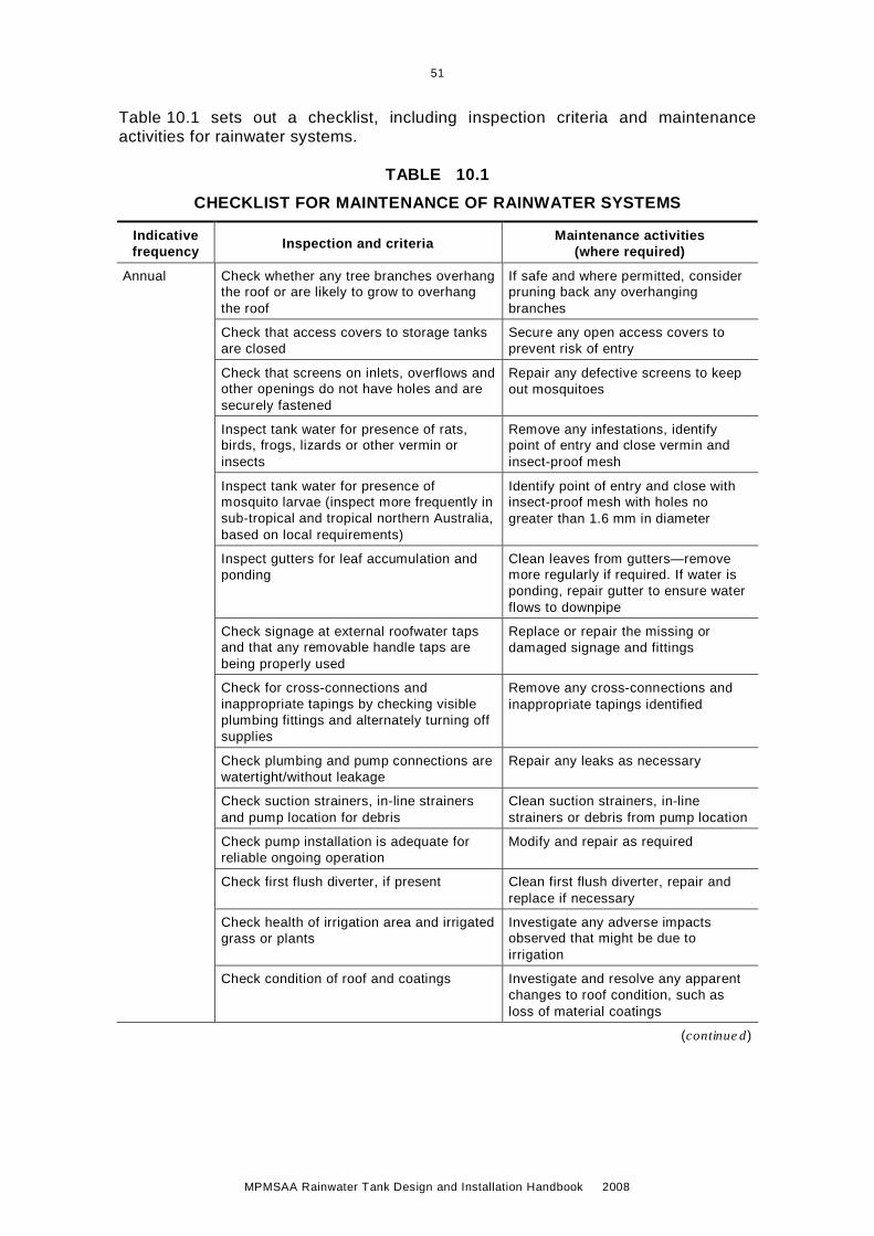
51
MPMSAA Rainwater Tank Design and Installation Handbook 2008
Table 10.1 sets out a checklist, including inspection criteria and maintenance activities for rainwater systems.
TABLE 10.1
CHECKLIST FOR MAINTENANCE OF RAINWATER SYSTEMS
Indicative frequency Inspection and criteria Maintenance activities
(where required)
Annual Check whether any tree branches overhang the roof or are likely to grow to overhang the roof
If safe and where permitted, consider pruning back any overhanging branches
Check that access covers to storage tanks are closed
Secure any open access covers to prevent risk of entry
Check that screens on inlets, overflows and other openings do not have holes and are securely fastened
Repair any defective screens to keep out mosquitoes
Inspect tank water for presence of rats, birds, frogs, lizards or other vermin or insects
Remove any infestations, identify point of entry and close vermin and insect-proof mesh
Inspect tank water for presence of mosquito larvae (inspect more frequently in sub-tropical and tropical northern Australia, based on local requirements)
Identify point of entry and close with insect-proof mesh with holes no greater than 1.6 mm in diameter
Inspect gutters for leaf accumulation and ponding
Clean leaves from gutters—remove more regularly if required. If water is ponding, repair gutter to ensure water flows to downpipe
Check signage at external roofwater taps and that any removable handle taps are being properly used
Replace or repair the missing or damaged signage and fittings
Check for cross-connections and inappropriate tapings by checking visible plumbing fittings and alternately turning off supplies
Remove any cross-connections and inappropriate tapings identified
Check plumbing and pump connections are watertight/without leakage
Repair any leaks as necessary
Check suction strainers, in-line strainers and pump location for debris
Clean suction strainers, in-line strainers or debris from pump location
Check pump installation is adequate for reliable ongoing operation
Modify and repair as required
Check first flush diverter, if present Clean first flush diverter, repair and replace if necessary
Check health of irrigation area and irrigated grass or plants
Investigate any adverse impacts observed that might be due to irrigation
Check condition of roof and coatings Investigate and resolve any apparent changes to roof condition, such as loss of material coatings
(continued)

52
MPMSAA Rainwater Tank Design and Installation Handbook 2008
Indicative frequency
Inspection and criteria Maintenance activities (where required)
Triennial Drain, clean out and check the condition of the tank walls and roof to ensure no holes have arisen due to tank deterioration
Repair any tank defects
Check sediment levels in the tank Organise a suitable contractor to remove accumulated sediment if levels are approaching those that may block tank outlets
Undertake a systematic review of operational control of risks to the system
Identify the reason for any problems during inspections and take actions to prevent failures occurring in future
After 20 years and then every 5 years
Monitor the effectiveness of the irrigation equipment to assess for any clogging due to algal growth
Clean or replace clogged equipment
Ongoing Inspect and follow up on any complaints or concerns raised that could indicate problems with the system
Repair or replace any problems that are notified
[Source: Australian Guidelines for Water Recycling—Phase 2B (2008)]
TABLE 10.1 (continued)

53
MPMSAA Rainwater Tank Design and Installation Handbook 2008
C H A P T E R 1 1 R E B A T E S A N D B U I L D I N G R E C O M M E N D A T I O N S
11.1 REBATES FOR RAINWATER PRODUCTS AND INSTALLATIONS
TABLE 11.1
MAJOR REBATES FOR INSTALLATION OF RAINWATER TANKS AND CONNECTION TO RESIDENTIAL PROPERTIES IN
STATES AND TERRITORIES OF AUSTRALIA
State Approval required to obtain rebate
Link to website
ACT ACT Government www.thinkwater.act.gov.au
NSW NSW Department of Environment and Climate Change
www.environment.nsw.gov.au/rebates/ccfrtw.htm
NT Northern Territory Government
www.nt.gov.au/nreta/water/wise
Qld Queensland Government, Dept. of Natural Resources and Water
www.nrw.qld.gov.au/water/saverscheme
SA SA Water www.sawater.com.au/SAWater/YourHome
Tas Hobart City Council www.hobartcity.com.au/HCC/STANDARD/PC_1041.html
Vic Our Water Our Future www.ourwater.vic.gov.au/ourwater
WA Water Corporation, Waterwise Rebate
http://portal.water.wa.gov.au/portal/page/portal/WiseWaterUse

54
MPMSAA Rainwater Tank Design and Installation Handbook 2008
11.2 BUILDING REQUIREMENTS FOR RAINWATER SYSTEMS
TABLE 11.2
REQUIREMENTS FOR SUSTAINABLE HOUSING RATING SYSTEMS IN STATES AND TERRITORIES ACROSS AUSTRALIA
Area System Comments
Aust Building Code of Australia (BCA)
On 1 May 2008, the requirement for alterations to achieve 5-Star will come into effect in the Building Code of Australia 2008, www.buildingcommission.com.au, the new standard for renovations or relocations and applies to the thermal performance of a home and does not require a solar hot water system or a rainwater tank for toilet flushing.
www.abcb.gov.au/go/thebca/aboutbca,
NABERS (the National Australian Built Environment Rating System) is a performance-based rating system for existing buildings. NABERS rates a building on the basis of its measured operational impacts on the environment (energy and water efficiency). NABERS is a national initiative managed by the NSW Department of Environment and Climate Change.
Website www.nabers.com.au
NSW BASIX BASIX, the Building Sustainability Index, ensures homes are designed to use less potable water and be responsible for fewer greenhouse gas emissions by setting energy and water reduction targets for houses and units. Since 1 October 2006, BASIX applies to all new residential dwellings and any alteration/ addition throughout NSW. Some of the features of BASIX are rainwater tanks, plumbed to toilet, garden and/or laundry; and greywater systems where appropriate.
Website www.basix.nsw.gov.au
Qld None identified Building Code of Queensland (BCQ) introduced an amendment to the building code for water saving measures (including greywater use) www.lgp.qld.gov.au/planning/?id=7036. As part of new energy and water-saving laws introduced from 1 March 2006, councils have the option to amend their planning instruments to mandate rainwater tanks for new houses in their region. Councils will have the discretion to allow for local factors, such as rainfall, and the demand for water in their area.
Website www.dip.qld.gov.au/sustainable-living/watertanks.html
SA Building sustainability and efficiency, Planning SA
Since 1 July 2006, South Australia building rules have required new dwellings and extensions or alterations greater than 50 m2 to have an additional water supply to supplement the mains water (e.g. rainwater tanks >1,000L, 3rd pipe recycled water, bore water). Some remote towns are exempt (check website below). The additional water supply has to be plumbed to a toilet, water heater or to cold water outlets in the laundry of a new or altered home.
Website www.planning.sa.gov.au/go/rainwater-tanks
Vic 5 Star The 5-Star Standard for all new houses in Victoria came into full effect on 1 July 2005. This means it is compulsory for new houses to have a rainwater tank (min. 2,000L and min. roof catchment of 50 m2) for toilet flushing or a solar hot water system. This does not include greywater as compulsory, but comments that builders and consumers who wish to go further than 5-Star have plenty of choices. This can include using greywater for gardens, car washing and toilet flushing, and consideration is being given to the use of rainwater for hot water. www.buildingcommission.com.au - (VBC 2005).
Website www.5starhouse.vic.gov.au/
(continued)

55
MPMSAA Rainwater Tank Design and Installation Handbook 2008
Area System Comments
WA Five Star Plus For Stage 2 (due in 2008), owners of new houses will be required to install plumbing to toilets to allow for alternative water supply and easy recycling of greywater at a later date and, where single dwellings are located on larger lots, an alternative water supply (such as rainwater tanks) for flushing toilets and for washing machines.
5-Star Plus is based around two new building codes, the Water Use in Houses Code and the Energy Use in Houses Code
Website www.5starplus.wa.gov.au/
ACT Requirements for sustainable water management
From 31 March 2008, property owners who are building, redeveloping or significantly extending their properties will need to demonstrate how they meet a new 40% water efficiency target. This applies to all residential, commercial and industrial developments. This includes an option for rainwater tanks to be connected to at least toilet, laundry cold water, all external uses.
Website www.actpla.act.gov.au/topics/design_build/siting/water_efficiency
Tas Check with local responsible regulatory authority
NT Check with local responsible regulatory authority
Website www.nt.gov.au/infrastructure/bss/strategies/buildingcode.shtml
TABLE 11.2 (continued)

56
MPMSAA Rainwater Tank Design and Installation Handbook 2008
C H A P T E R 1 2 R A I N F A L L D A T A
This Section contains a summary of historical rainfall data for cities across Australia, extracted from the Australian Bureau of Meteorology. This data can be used to estimate a maximum volume of rainwater that can be captured using the formula from Clause 13.2.

MP
MS
AA
Rainw
ater Tank D
esign and Installation Handbook 2008
57
TABLE 12.1
RAIN AND RANGE OF RAINFALL FOR CITIES/TOWNS IN AUSTRALIA (MM/MONTH)
Jan Feb Mar Apr May Jun Jul Aug Sep Oct Nov Dec Annual Statistic A
Adelaide
21 9 20 33 57 82 69 69 58 39 31 24 553 Median
4-39 0-28 1-59 9-82 15-91 33-125 36-115 26-107 28-84 15-81 8-53 9-56 378-674 Range
Albany
15 16 31 62 115 125 145 117 93 72 40 23 924 Median
5-42 4-54 10-77 26-119 59-183 80-196 84-204 79-187 53-158 38-131 15-73 9-65 743-1112 Range
Albury
27 33 26 30 50 67 83 88 63 75 52 41 760 Median
10-124 3-84 2-85 12-110 15-108 30-105 39-147 27-134 34-115 11-115 16-103 13-117 475-898 Range
Alice Springs
13 14 11 2 7 4 3 2 1 18 20 24 237 Median
2-101 0-149 0-65 0-45 0-61 0-37 0-36 0-27 0-26 1-54 2-65 3-73 125-456 Range
Bendigo
23 22 11 24 40 40 49 41 40 46 34 30 460 Median
10-59 4-59 4-48 4-51 12-86 21-94 18-87 12-80 21-91 8-82 16-83 1-94 302-682 Range
Brisbane
94 93 67 48 67 51 25 26 26 55 106 116 886 Median
49-253 36-208 28-153 15-82 15-170 6-161 1-39 4-106 6-62 31-128 48-166 58-212 624-1232 Range
Broome
114 165 71 4 4 1 1 1 1 0 1 33 533 Median
16-386 28-384 6-267 0-81 0-89 0-74 0-13 0-3 0-2 0-4 0-30 3-134 316-991 Range
(continued)

MP
MS
AA
Rainw
ater Tank D
esign and Installation Handbook 2008
58
Jan Feb Mar Apr May Jun Jul Aug Sep Oct Nov Dec Annual Statistic A
Cairns
335 403 378 167 86 35 24 19 19 28 65 127 1938 Median
117-634 170-750 136-739 71-403 27-175 11-93 6-59 4-62 2-85 5-83 16-213 43-340 1323-2782 Range
Canberra
49 55 32 33 38 32 36 46 53 55 60 42 618 Median
10-115 4-107 4-118 8-102 7-96 9-94 10-86 12-76 15-86 20-127 21-112 10-112 390-805 Range
Darwin
409 353 293 75 5 0 0 0 6 52 142 221 1698 Median
208-663 157-633 137-531 16-212 0-56 0-3 0-5 0-13 0-39 4-152 58-220 102-409 1220-2150 Range
Devonport
35 30 38 51 67 81 92 83 76 62 53 47 763 Median
16-88 6-66 6-89 15-116 28-138 34-122 44-159 36-152 26-118 27-118 21-93 12-102 575-1007 Range
Gold Coast
111 144 98 88 83 57 33 49 25 85 101 128 1190 Median
45-167 45-316 20-160 29-120 38-228 24-291 1-120 12-164 12-105 31-132 43-235 72-175 919-1415 Range
Hobart
39 32 37 46 38 44 47 45 42 54 49 47 596 Median
12-95 8-83 15-85 15-83 17-86 18-90 22-93 19-103 22-96 26-107 21-87 15-115 460-781 Range
Kalgoorlie
4 9 14 9 22 21 21 16 8 12 7 9 230 Median
0-45 0-55 0-89 0-60 3-62 7-53 7-39 6-50 1-23 0-37 0-34 0-50 143-345 Range
(continued)
Katherine
TABLE 12.1 (continued) TABLE 12.1 (continued)

MP
MS
AA
Rainw
ater Tank D
esign and Installation Handbook 2008
59
Jan Feb Mar Apr May Jun Jul Aug Sep Oct Nov Dec Annual Statistic A
233 264 170 19 0 0 0 0 0 21 86 164 1106 Median
117-435 98-386 28-456 0-115 0-4 0-1 0-0 0-2 0-33 1-99 28-133 86-393 756-1442 Range
Launceston
39 24 31 42 54 59 74 67 69 53 48 43 696 Median
18-87 7-60 7-69 20-87 22-117 31-107 44-113 33-153 30-102 20-83 20-74 13-72 543-776 Range
Melbourne
37 32 38 50 55 43 47 49 53 68 52 51 646 Median
11-99 7-107 12-106 18-115 21-91 26-85 23-72 24-78 28-93 28-111 21-113 18-110 472-824 Range
Mount Gambier
19 21 26 44 68 80 96 85 73 57 48 34 699 Median
6-54 4-55 7-63 17-97 30-128 41-144 51-144 52-145 43-101 24-106 16-75 13-63 544-855 Range
Newcastle
72 88 96 91 102 85 81 59 57 63 64 63 1058 Median
25-175 20-216 30-255 27-237 23-229 22-246 15-199 13-140 18-148 18-142 15-135 20-157 798-1545 Range
Perth
2 4 9 27 93 123 138 131 91 42 18 5 741 Median
0-40 0-24 3-53 9-65 39-135 62-214 94-223 98-166 61-113 17-80 6-33 0-16 653-885 Range
Port Lincoln
9 12 14 28 54 70 74 68 48 31 17 14 487 Median
1-29 1-34 2-40 8-69 26-92 30-125 41-129 33-106 21-85 13-67 4-49 3-39 374-620 Range
(continued)
Sydney
80 92 101 92 91 96 75 57 53 56 67 59 1164 Median
TABLE 12.1 (continued)

MP
MS
AA
Rainw
ater Tank D
esign and Installation Handbook 2008
60
Jan Feb Mar Apr May Jun Jul Aug Sep Oct Nov Dec Annual Statistic A
28-192 20-256 30-282 24-272 19-268 24-293 10-221 10-187 14-156 17-175 17-155 22-172 821-1658 Range
Townsville
205 226 138 30 20 9 3 5 2 14 32 78 1069 Median
41-518 57-571 22-412 3-173 2-86 0-73 0-30 0-41 0-31 1-54 4-132 19-350 590-1728 Range
Wollongong
110 111 144 72 73 80 51 29 51 62 98 75 1309 Median
41-249 50-358 26-348 18-314 23-238 22-254 9-160 6-253 9-152 13-248 35-225 26-203 865-1863 Range
NOTE: Single values are median (most expected) and range of values is the 10th to 90th percentile of all available data from www.bom.gov.au/climate/averages/ (accessed – April 2008).

61
MPMSAA Rainwater Tank Design and Installation Handbook 2008
C H A P T E R 1 3 C A L C U L A T I N G E X P E C T E D A N N U A L R A I N W A T E R C A T C H M E N T
13.1 GENERAL
There are a number of factors that need to be considered when calculating the expected annual rainwater catchment from a particular roof or other harvesting areas, which will in turn help determine the size of the rainwater tank and the potential intended use. These are as follows:
(a) Rainfall for the region—Rainfall data (Chapter 12) from Bureau of Meteorology, local rainfall stations and responsible regulatory authorities.
(b) Catchment size—Square metres of specific roof catchment area discharging to tank (Figure 13.1).
(c) Pre-treatment—Devices (first flush, etc.) that may divert rainwater away from storage tank.
(d) Coefficient run-off percentage from catchment area—For example, an impervious surface such as a metal or tiled roof will have a higher coefficient run-off percentage than a grassed area where a large percentage of water would be absorbed.
13.2 FORMULA
Annual rainfall (mm)
× catchment area (m2) × coefficient
run-off (%) × percentage of diverted water
(%) =
maximum litres of
rainfall per year
1000 L = 1000 kg
1 millimetre (mm) rainfall × 1 square metre (m2) of roof catchment = 1 litre (L) of rainwater
NOTE: Areas should be related to downpipe connected to the tank.

62
MPMSAA Rainwater Tank Design and Installation Handbook 2008
FIGURE 13.1 TYPICAL ROOF AREA CALCULATION (AS/NZS 3500.3:2003), INCLUDES WIDTH OF EAVES AND GUTTERS
13.3 RAINWATER COLLECTION CALCULATIONS
13.3.1 Sydney example—Calculation 1
There is a tiled roof on a residential house in Sydney, where 70 m2 roof area is draining to a single downpipe where the householder would like to capture and store the roofwater in a rainwater tank nearby.
Most likely annual rainfall for the Sydney region (1164 mm/year) (Chapter 12):
(a) Catchment size—Square metres of specific roof catchment area discharging to tank (70 m2).
(b) Coefficient run-off percentage from catchment area tiled roof, assume 90% coefficient rate for metal or tiled roofs (see Note 2).
(c) Pre-treatment devices—No device.
Answer: 1164 × 70 × 0.90 = 73,332 L per year of rainwater (best case – see Note 1)
13.3.2 Perth example—Calculation 2
There is a metal roof on a residential house in Perth where 200 m2 roof area is draining to four downpipes where they would like to capture and store the roofwater in an underground rainwater tank nearby, with a first flush device diverting 20 L each time it rains.
Most likely annual rainfall for the Perth region (741 mm/year) (Chapter 12):
(a) Catchment size—Square metres of specific roof catchment area discharging to tank (200 m2).
(b) Coefficient run-off percentage from catchment area tiled roof, assume 90% coefficient rate for metal or tiled roofs (see Note 2).
(c) Pre-treatment devices—20 L per rainfall event (assume 50 rainfall events—1000 L).
Answer: (741 × 200 × 0.90) – 1000 L = 132,380 L per year of rainwater (best case – see Note 1)
13.3.3 Queensland example—Calculation 3
There is a metal roof on a residential house in Townsville (Queensland) where 150 m2 roof area is draining to two downpipes where they would like to capture and store the roofwater in a concrete above-ground rainwater tank, with a first flush device diverting 20 L each time it rains.
Rainfall for the Townsville region (1069 mm/year) (Chapter 12).
(a) Catchment size—Square metres of specific roof catchment area discharging to tank (150 m2).
(b) Coefficient run-off percentage from catchment area tiled roof, assume 90% coefficient rate for metal or tiled roofs (see Note 2).
(c) Pre-treatment devices—20 L per rainfall event (assume 30 rainfall events—600 L).
Answer: (1069 × 150 × 0.90) – 600 L = 143,715 L per year of rainwater (best case - see Note 1)

63
MPMSAA Rainwater Tank Design and Installation Handbook 2008
NOTES to calculations in Clause 13.3. NOTES: 1 Rainfall frequency in your area, specific tank sizes and rainwater use will influence the total
rainfall available for use. In some instances there will be overflow from the tanks during a rainfall event and other cases rainwater will not be available (tank empty) through lack of rainfall.
2 A range of run-off percentage coefficients are used across Australia depending on roofing materials, pre-treatment devices and climatic conditions.

64
MPMSAA Rainwater Tank Design and Installation Handbook 2008
C H A P T E R 1 4 A V E R A G E W A T E R C O N S U M P T I O N V A L U E S F O R U R B A N
A C T I V I T I E S
14.1 GENERAL
Water usage volumes for certain activities around a domestic home can vary greatly, depending on the number of people residing within the home, the type of appliances and fixtures inside the home (e.g. water efficiency) and the size and type of garden.
Tables 14.1, 14.2, 14.3, 14.4, 14.5 and 14.6 provide estimates of most likely water requirements for gardens, warm and cold season grasses and toilets. Table 14.7 provides average distribution of water consumption percentages in Australian households.
The figures in the tables are only a guide to the average or most likely water consumption for certain activities around a domestic home. More accurate figures can be obtained from an individual water audit or investigating the individual consumption readings obtained from a water bill from your local water retailer. Water use will depend on the type of garden and lawn grown, rainfall and evaporation in the area, and the type of irrigation systems used.

65
MPMSAA Rainwater Tank Design and Installation Handbook 2008
TABLE 14.1
ESTIMATE OF MOST LIKELY WATER REQUIREMENTS FOR A DROUGHT TOLERANT GARDEN
City
Area of garden (m2)
100 200 300 400 500 600
Estimate of most likely water requirements (L/year)
Adelaide 15,400 30,900 46,300 61,800 77,200 92,700
Albany 12,000 23,900 35,900 47,800 59,800 71,700
Albury 10,400 20,800 31,200 41,600 52,000 62,400
Alice Springs 75,400 150,800 226,200 301,600 377,000 452,400
Bendigo 16,000 32,100 48,100 64,100 80,200 96,200
Brisbane 1,400 2,900 4,300 5,700 7,100 8,600
Broome 54,200 108,500 162,700 216,900 271,100 325,400
Cairns 11,900 23,900 35,800 47,800 59,700 71,700
Canberra 6,500 12,900 19,400 25,800 32,300 38,700
Darwin 30,600 61,200 91,900 122,500 153,100 183,700
Gold Coast 1,100 2,200 3,300 4,400 5,500 6,600
Hobart 400 700 1,100 1,500 1,800 2,200
Katherine 37,500 75,100 112,600 150,200 187,700 225,300
Launceston 7,000 14,100 21,100 28,200 35,200 42,200
Melbourne 2,400 4,800 7,200 9,600 12,000 14,300
Mount Gambier 9,400 18,700 28,100 37,400 46,800 56,200
Newcastle 700 1,400 2,100 2,800 3,400 4,100
Perth 27,900 55,800 83,700 111,600 139,500 167,300
Port Lincoln 20,500 41,100 61,600 82,100 102,700 123,200
Sydney 1,200 2,400 3,500 4,700 5,900 7,100
Townsville 35,300 70,500 105,800 141,100 176,400 211,600

66
MPMSAA Rainwater Tank Design and Installation Handbook 2008
TABLE 14.2
ESTIMATE OF MOST LIKELY WATER REQUIREMENTS FOR A GARDEN WITH HIGH WATER REQUIREMENTS
City
Area of garden (m2)
100 200 300 400 500 600
Estimate of most likely water requirements (L/year)
Adelaide 58,300 116,700 175,000 233,300 291,700 350,000
Albany 42,800 85,500 128,300 171,000 213,800 256,500
Albury 44,300 88,600 132,900 177,200 221,500 265,800
Alice Springs 187,800 375,600 563,400 751,200 939,000 1,126,800
Bendigo 58,500 117,000 175,500 234,000 292,500 351,000
Brisbane 24,800 49,600 74,500 99,300 124,100 148,900
Broome 143,800 287,700 431,500 575,300 719,200 863,000
Cairns 54,800 109,500 164,300 219,100 273,800 328,600
Canberra 58,200 116,300 174,500 232,600 290,800 349,000
Darwin 85,700 171,400 257,000 342,700 428,400 514,100
Gold Coast 14,800 29,500 44,300 59,000 73,800 88,500
Hobart 15,500 31,000 46,400 61,900 77,400 92,900
Katherine 95,800 191,600 287,400 383,200 479,000 574,700
Launceston 39,200 78,300 117,500 156,700 195,900 235,000
Melbourne 27,700 55,300 83,000 110,700 138,400 166,000
Mount Gambier 41,800 83,600 125,400 167,200 208,900 250,700
Newcastle 33,000 65,900 98,900 131,800 164,800 197,800
Perth 77,600 155,300 232,900 310,500 388,200 465,800
Port Lincoln 62,700 125,400 188,100 250,800 313,500 376,300
Sydney 35,000 69,900 104,900 139,800 174,800 209,700
Townsville 104,600 209,200 313,800 418,400 523,000 627,600

67
MPMSAA Rainwater Tank Design and Installation Handbook 2008
TABLE 14.3
ESTIMATE OF MOST LIKELY WATER REQUIREMENTS FOR WARM SEASON GRASSES
City
Area of garden (m2)
100 200 300 400 500 600
Estimate of most likely water requirements (L/year)
Adelaide 37,300 74,500 111,800 149,000 186,300 223,500
Albany 31,000 62,000 93,000 124,000 155,000 186,000
Albury 28,900 57,700 86,600 115,400 144,300 173,200
Alice Springs 142,200 284,500 426,700 568,900 711,200 853,400
Bendigo 40,200 80,500 120,700 161,000 201,200 241,500
Brisbane 11,100 22,200 33,300 44,400 55,500 66,600
Broome 104,700 209,300 314,000 418,600 523,300 627,900
Cairns 37,000 73,900 110,900 147,900 184,800 221,800
Canberra 35,900 71,900 107,800 143,800 179,700 215,600
Darwin 59,900 119,800 179,600 239,500 299,400 359,300
Gold Coast 5,700 11,300 17,000 22,700 28,400 34,000
Hobart 7,800 15,700 23,500 31,400 39,200 47,100
Katherine 73,100 146,200 219,400 292,500 365,600 438,700
Launceston 25,200 50,400 75,600 100,800 126,100 151,300
Melbourne 14,400 28,800 43,200 57,600 72,000 86,400
Mount Gambier 26,900 53,900 80,800 107,800 134,700 161,600
Newcastle 14,500 29,000 43,600 58,100 72,600 87,100
Perth 57,700 115,300 173,000 230,700 288,300 346,000
Port Lincoln 46,300 92,600 138,800 185,100 231,400 277,700
Sydney 17,000 33,900 50,900 67,900 84,800 101,800
Townsville 73,500 147,000 220,500 294,000 367,500 441,000
NOTE: Examples of warm season grasses include Buffalo grass, Kikuyu and Seashore paspalum.

68
MPMSAA Rainwater Tank Design and Installation Handbook 2008
TABLE 14.4
ESTIMATE OF MOST LIKELY WATER REQUIREMENTS FOR COOL SEASON GRASSES
City
Area of garden (m2)
100 200 300 400 500 600
Estimate of most likely water requirements (L/year)
Adelaide 67,700 135,400 203,000 270,700 338,400 406,100
Albany 51,900 103,800 155,700 207,500 259,400 311,300
Albury 54,100 108,300 162,400 216,600 270,700 324,900
Alice Springs 217,600 435,100 652,700 870,300 1,087,800 1,305,400
Bendigo 69,100 138,200 207,200 276,300 345,400 414,500
Brisbane 37,300 74,600 111,900 149,200 186,500 223,800
Broome 165,100 330,300 495,400 660,500 825,700 990,800
Cairns 70,000 140,000 210,000 280,000 350,000 420,000
Canberra 73,100 146,300 219,400 292,600 365,700 438,800
Darwin 100,700 201,300 302,000 402,600 503,300 604,000
Gold Coast 23,500 47,000 70,500 93,900 117,400 140,900
Hobart 20,400 40,700 61,100 81,400 101,800 122,200
Katherine 113,800 227,600 341,400 455,200 569,000 682,800
Launceston 49,200 98,400 147,500 196,700 245,900 295,100
Melbourne 34,300 68,700 103,000 137,300 171,700 206,000
Mount Gambier 50,400 100,700 151,100 201,500 251,900 302,200
Newcastle 44,200 88,500 132,700 176,900 221,100 265,400
Perth 89,000 177,900 266,900 355,800 444,800 533,700
Port Lincoln 74,900 149,900 224,800 299,800 374,700 449,600
Sydney 48,800 97,700 146,500 195,300 244,200 293,000
Townsville 122,700 245,400 368,200 490,900 613,600 736,300
NOTE: Examples of cool season grasses are Annual Blue Grass, Hard Fescue, Kentucky bluegrass and Tall Fescue.

69
MPMSAA Rainwater Tank Design and Installation Handbook 2008
TABLE 14.5
INDOOR WATER USE ESTIMATES FOR TOILETS
WELS rating (Stars)
Household appliance
(Full flush L/low flush L)
Number of people residing in household For each extra
person 1 2 3 4 5
Toilet flushing (L/year)
0 Single flush (11/flush)
20,100 40,200 60,200 80,300 100,400 20,100
0 Dual flush 11/5 11,300 22,600 33,900 45,300 56,600 11,300
1 Dual flush 9/4.5 9,900 19,700 29,600 39,400 49,300 9,900
3 Dual flush 6/3 6,600 13,100 19,700 26,300 32,900 6,600
4 Dual flush 4.5/3 6,000 12,000 18,100 24,100 30,100 6,000
NOTE: All figures are in litres per year (local housing type and occupants’ age may vary the above consumption volumes). Toilet flushing figures based on AS/NZS 1172 & AS/NZS 6400. Old plumbing systems designed for larger volume flushing toilets may not perform to expectation when new 4.5/3 L pans have been installed. If in doubt, evaluate the system before installing new pans.
TABLE 14.6
ESTIMATE OF WATER REQUIREMENTS FOR FRONT AND TOP LOADING WASHING MACHINES
Number of
residents
Number of
washes per week
Greywater generation—Washing machine (L/week)
Front loading washing machine Top loading washing machine
Small (up to 5.5 kg)
Medium (6−−−−7 kg)
Large (over
7.5 kg)
Small (up to 5.5 kg)
Medium (6–7 kg)
Large (over
7.5 kg)
1 2 5,356 6,916 8,528 10,920 14,196 17,472
2 3 8,008 10,400 12,792 16,380 21,320 26,208
3 4 10,660 13,884 17,056 21,840 28,392 34,944
4 6 16,016 20,800 25,584 32,760 42,588 52,416
5 7 18,668 24,232 29,848 38,220 49,712 61,152
6 8 21,320 27,716 34,112 43,680 56,784 69,888
7 9 23,972 31,200 38,376 49,140 63,908 78,624
(Source: NSW Guidelines for Greywater Reuse in Sewered, Single Household Residential Premises.)
Assumptions: Top Loading: average machine is larger (over 7.5 kg) with a 2-star WELS rating. Front loading: average machine is medium (6−7 kg) with a 4-star WELS rating. For one unit increase in stars there is approximately a 30% decrease in water requirements per load.
NOTE: Many washing detergents can be detrimental to the environment, if unsure it is recommended that the first wash be directed to sewer not greywater reuse. If this is the case, the volume of greywater produced from a washing machine will be less than stated in this table.

70
MPMSAA Rainwater Tank Design and Installation Handbook 2008
TABLE 14.7
AVERAGE DISTRIBUTION OF WATER CONSUMPTION
IN AUSTRALIAN HOUSEHOLDS
Water use Percentage of water
Garden* 35–50%
Bathroom 20%
Hot Water 15−25%
Toilet flushing 10−20%
Laundry 10−20%
Kitchen 5%
(Source: Water Services Association of Australia) Garden water usage may vary considerably due to water restrictions in drought-affected areas.

71
MPMSAA Rainwater Tank Design and Installation Handbook 2008
C H A P T E R 1 5 A C C E P T A B L E R A I N W A T E R I N S T A L L A T I O N S T E C H N I C A L D R A W I N G S
15.1 GENERAL
The technical installation drawings on the following pages (Figures 15.1 to 15.17) are intended to be in accordance with AS/NZS 3500 series. Where there are differences, the requirements of AS/NZS 3500 apply.
Variations may occur, check with the local responsible regulatory authority. NOTE: Clarification on the following diagrams—not all optional devices discussed in this Handbook are shown on each installation diagram.
15.2 ABOVE-GROUND RAINWATER TANK INSTALLATION
15.2.1 Common above-ground rainwater tank systems
Figures 15.1 to 15.6 provide common above-ground rainwater tank installation diagrams, which cover the following:
• Basic above-ground tank for garden irrigation use only.
• Tank with charged (wet) system for all downpipes.
• Tank with charged (wet) system for all downpipes and sump pump for rainwater.
• Tank with mains water top-up and rainwater supplied to appliances in the household.
Max. ra inwater leve l
Roof catchment area
Roof dra inage systemto AS/NZS 3500 ser ies
Min. 100 mm
Tank over f low
pipe min. 100 mm øGardenir r igat iontap
Rainwaters ignage
Bedding for tank,refer to tank manufacturer
Min.150 mm
Bo
un
da
ry
# For setback distance pleasecontact responsib le regulator yauthor i ty
Stormwater dra inagepipework
DiameterøFSL
FSL
Finished sur face level
Pre-storage f i l te rand insect /vermincontrol
Stormwater over f lowto approved stormwaterdischarge point
Set back#
FIGURE 15.1 BASIC ABOVE-GROUND RAINWATER TANK FOR GARDEN IRRIGATION USE ONLY—CROSS-SECTION

72
MP
MS
AA
Rainw
ater Tank D
esign and Installation Handbook 2008
Max. rainwater level
Insect / vermin control mesh(pre-storage f i lter)
Roof catchment area
Roof drainage systemto AS/NZS 3500 series
Min. 100mm
Tank over f low
pipe min. 100 mm ø
Bedding for tank,refer to tank manufacturer
Bo
un
da
ry
# For setback distance pleasecontact responsib le regulator yauthor i ty
Stormwater drainagepipework
DiameterøFSL
Vent (surcharge)screen mesh f i lter
fsl
Finished sur face level
Air vent withinsect/vermin control
Interconnection pipesize to AS/NZS 3500 series
Stormwater over f lowto approved stormwaterdischarge point
Set back #
NOTE: Overflow must be on the rainwater inlet tank or interconnecting pipework must be equal to the rainwater inlet capacity.
FIGURE 15.2 CONNECTION OF RAINWATER TANKS ABOVE-GROUND

73
MP
MS
AA
Rainw
ater Tank D
esign and Installation Handbook 2008
Maximum tankra inwater leve l
Roof catchment area
Min. 300 mm Tank over f low pipe to AS/NZS 3500 series
Gardenir r igat iontap
Rainwaters ignage
Bedding for tank,refer to tank manufacturer
Min. 150 mm
Maximum pipera inwater leve l
Set back
Bo
un
da
ry
Water tight stormwaterdrainage around perimeterof bui ld ing
Stormwater drainagepipework
Finished sur face levelFSL
#
Inspection opening
Vent (surcharge)screen mesh f i l te r
# For setback distance pleasecontact responsib le regulator yauthor i ty
Insect /vermin andl ight contro l
FSL
Pre-storage f i l te rand insect /vermin
control
Stormwater over f lowto approved stormwaterdischarge point
Water t ightdra inage point
Dra inagepit
NOTE: On sloping sites drainage point can be extended down the slope without the need for a drainage pit, check with responsible regulatory authority.
FIGURE 15.3 ABOVE-GROUND RAINWATER TANK INSTALLATION WITH CHARGED (WET) SYSTEM FOR ALL DOWNPIPES—CROSS-SECTION (DOWNPIPES TO AS/NZS 3500 series.)

74
MPMSAA Rainwater Tank Design and Installation Handbook 2008
Tank over f lowpipe min.100 mm øWater t ight stormwater
dra inage aroundper imeter of bui ld ing
Downpipe
Downpipe
Downpipe
Downpipe
Tap
Water t ightdra inage point
Stormwater drainagepipework
DiameterøRoof catchment area
Drainage pit NOTE: On sloping sites, drainage point can be extended down the slope without the need for a drainage pit; check with responsible regulatory authority.
FIGURE 15.4 ABOVE-GROUND RAINWATER TANK INSTALLATION WITH CHARGED (WET) SYSTEM FOR ALL DOWNPIPES—PLAN VIEW OF FIGURE 15.2 (DOWNPIPES
AND ROOF CATCHMENT AREA TO AS/NZS 3500)

75
MP
MS
AA
Rainw
ater Tank D
esign and Installation Handbook 2008
Maximum tankrainwater level
Roof catchment area
Min. 100 mm Tank over f low pipeto AS 3500 series
Gardenirr igationtap
Rainwatersignage
Bedding for tank,refer to tank manufacturer
Min.150 mm
Max. piperainwater level
Set back
Bo
un
da
ry
Water tight stormwater drainagearound perimeter of building
Stormwater drainagepipework
* For setback distance pleasecontact responsib le regulator yauthor i ty
*
Pit pump
¥
Vent (surcharge)with insect / vermin control
Pit pump controler
Tank levelswitch forpit pump
Insect/vermin andlight control
Control wire
Inspection opening must belockable. If water tight canbe f lush with FSL.If not water tight min 150 mmabove FSL
¥
Finished sur face levelFSL
FSL
Pump
Reflux valve
Pre-storage f i lter and insect/vermin
control
Stormwater over f lowto approved stormwaterdischarge point
FIGURE 15.5 ABOVE-GROUND RAINWATER TANK INSTALLATION WITH CHARGED (WET) SYSTEM FOR ALL DOWNPIPES AND SUMP PUMP FOR STORMWATER OVERFLOW (DOWNPIPES TO AS/NZS 3500 SERIES)

76
MP
MS
AA
Rainw
ater Tank D
esign and Installation Handbook 2008
wc
Roof dra inage systemto AS/NZS 3500 ser ies
Min. 100 mmTank over f low pipe to AS/NZS 3500 ser ies
Bedding for tank,refer to tank manufacturer
Bo
un
da
ry
Pump
Mains watersupply
¥ 240v required
* For setback distance pleasecontact responsib le regulator yauthor i ty
¥
Set back *
Stop tap ( isolation valve)
Non return valve
Rainwater pipework
Stormwater drainagepipework
Finished sur face level
DiameterøFSL
Mains pipework(potable or drinking water)
Pump
Meter
Roofcatchment
area
(Optional )Interconnect ion
device & pump posi t ion
Rainwatersignage
Vent (surcharge) with insect / vermin contro l
Maximumrainwaterlevel
(Optional )mains watertopup devicevisable air gap
Tap
(Optional )Water supply to house through
post-storage f i l tration
Back f low prevent ion device (non-return or s ingle check va lvein accordance with AS/NZ 3500 ser ies)
Back f lowprevent ion device in accordancewith AS/NZ 3500ser ies
Mainswater
Back f low prevent ion device asrequired by the network ut i l i t yoperators requirements
Pre-storage f i l te rinsect / vermin andl ight contro l
FSLStormwater over f lowto approved stormwaterdischarge point
FIGURE 15.6 ABOVE-GROUND RAINWATER TANK INSTALLATION WITH MAINS WATER TOP-UP AND RAINWATER SUPPLIED TO APPLIANCES IN THE HOUSEHOLD

77
MP
MS
AA
Rainw
ater Tank D
esign and Installation Handbook 2008
Roof dra inage system toAS/NZS 3500 ser ies
Tank over f low pipe toAS/NZS 3500 ser ies
¥ 240 V required
Roofcatchment
area
Max.ra inwaterlevel
Garden i r r igat ion tap
¥Submers ib le pump
Pit withlockable l id
Vent (surcharge) withinsect / vermin contro l
Rainwater s ignage
Optionalsubmers ib le pump
¥
Water forex ternal orinternal use
Bo
un
da
ry
Tank levelswitch forpi t pump
Pit pumpcontrol le r
Rainwater pipework
Stormwater drainagepipework
Control wire
Roof water f romaddit ional downpipes
Pre-storage f i l te r insect / vermin and l ight contro l
Reflux valve
Pump
Pre-storagefi lter andinsect / vermincontrol
Set back
* For setback distance pleasecontact responsib le regulator yauthor i ty
*
Stormwater over f lowto approved stormwaterdischarge pointwith back f lowprevent ion device(ref lux va lve)
FIGURE 15.7 ABOVE-GROUND TANK WITH PIT PUMP INSTALLATION—UNCHARGED (DRY) SYSTEM

78
MP
MS
AA
Rainw
ater Tank D
esign and Installation Handbook 2008
15.2.2 Ab
ove-g
rou
nd
rainw
ater tank in
stallation
on
slop
ing
gro
un
d
Roof catchment area
Water t ight
A ir vent withinsect / vermin contro l
Rainwater accessand dra inage
Stormwater dra inagepipework
Max. waterlevel
Ref lux va lve
Finished sur face levelFSL
FSL
FSL
Pre-storage f i l te rand insect / vermin
control
Min. 150 mm
Stormwater over f lowto approved stormwaterdischarge point
FIGURE 15.8 RAINWATER TANK INSTALLATION ON SLOPING GROUND—CHARGED (WET) SYSTEM WITH OVERFLOW TO STORMWATER

79
MP
MS
AA
Rainw
ater Tank D
esign and Installation Handbook 2008
Roof catchment area
Tank stand to bedesigned and engineeredaccordingly
Footing as perengineered design
Stormwater dra inagepipework
Insect / vermin andl ight contro l
Ref lux va lve
Finished sur face levelFSL
FSL
FSL
Pre-storage f i l te r and insect / vermin
control
Stormwater over f lowto approved stormwaterdischarge point
Rainwater accessand dra inage
Min. 150 mm
FIGURE 15.9 RAINWATER TANK INSTALLATION ON SLOPING GROUND—UNCHARGED (DRY) SYSTEM BELOW LEVEL OF HOUSE

80
MP
MS
AA
Rainw
ater Tank D
esign and Installation Handbook 2008
Roof catchment area
Stormwater dra inagepipework
Ref lux va lve
Finished sur face levelFSL
FSL
FSL
Pre-storage f i l te rand insect / vermincontrol
Tank stand to bedesigned and engineeredaccordingly
Footing as perengineered design
Stormwater over f lowto approved stormwaterdischarge point
Rainwater accessand dra inage
Min. 150 mm
FIGURE 15.10 RAINWATER TANK INSTALLATION ON SLOPING GROUND—UNCHARGED (DRY) SYSTEM AT LEVEL OF HOUSE
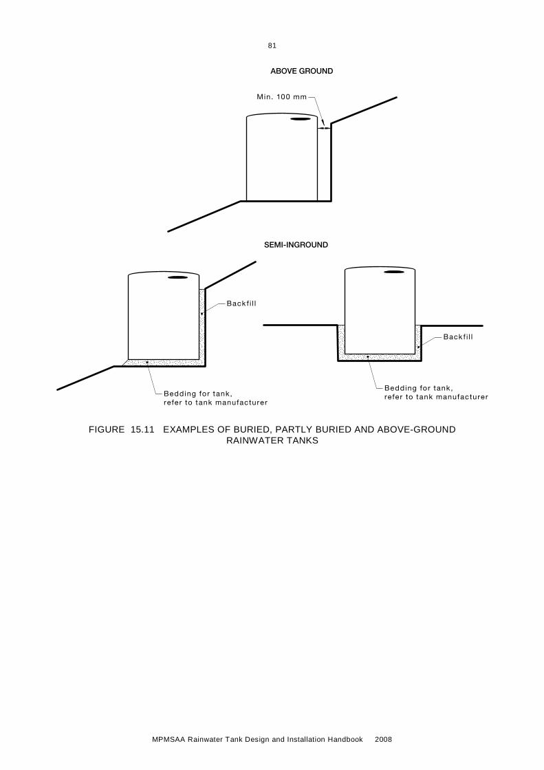
81
MPMSAA Rainwater Tank Design and Installation Handbook 2008
Min. 100 mm
Bedding for tank,refer to tank manufacturer
Bedding for tank,refer to tank manufacturer
Back f i l l
Back f i l l
SEMI-INGROUND
ABOVE GROUND
FIGURE 15.11 EXAMPLES OF BURIED, PARTLY BURIED AND ABOVE-GROUND RAINWATER TANKS

82
MP
MS
AA
Rainw
ater Tank D
esign and Installation Handbook 2008
15.3 UN
DE
R-G
RO
UN
D R
AIN
WA
TE
R T
AN
K IN
ST
AL
LA
TIO
N
Max.rainwater level
Roof catchment area
Roof drainage systemto AS/NZS 3500 series
Pipe ø min. to AS/NZS 3500 series
Gardenirr igationtap
Bedding for tank,refer to tank manufacturer
45o
Angle of repose
Excavation area
Backfil l
Inspectionopening
Submersible pump
Float switch
Buildingfoundationfootings
Optional positionor pump type
*
¥
Bo
un
da
ry
¥
* Inspection opening must belockable. If water tight, it canbe f lush with FSL.If not water tight, min 150mm, itabove FSL
¥ 240 V required
+ For setback distance please
Setback +
Rainwater pipework
Stormwater drainagepipework
Finished sur face level
Diameterø
Pump
Rainwater signage
FSL
FSL
Reflux valve
Pre-storage f i lterand insect / vermincontrol
Stormwater over f low to approvedstormwater discharge point withbackflow prevention device (ref lux valve)
contact responsib le regulator yauthor i ty
FIGURE 15.12 UNDERGROUND RAINWATER TANK INSTALLATION—GARDEN USE
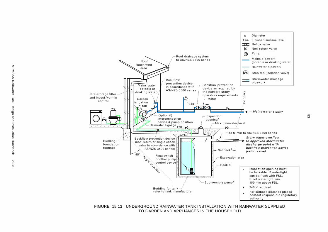
83
MP
MS
AA
Rainw
ater Tank D
esign and Installation Handbook 2008
Max. rainwater level
Roofcatchment
area
Roof drainage systemto AS/NZS 3500 series
Pipe ø min to AS/NZS 3500 series
Gardenirr igation
tap
Bedding for tankrefer to tank manufacturer
45o
Angle of repose
Excavation area
Back f i l l
Inspectionopening
Submersible pump
Float switchor other pumpcontrol device
Buildingfoundationfootings
Mains water supply
Meter
*
* Inspection opening mustbe lockable. If water tightcan be f lush with FSL.If not water tight min.150 mm above FSL
¥ 240 V required
Bo
un
da
ry
Set back
wc
+
+ For setback distance pleasecontact responsib le regulator yauthor i ty
¥
Stop tap ( isolation valve)
Non-return valve
Rainwater pipework
Stormwater drainagepipework
Finished sur face level
DiameterøFSL
Pump
Rainwater signage
(Optional )interconnectiondevice & pump position
Tap
Backflow preventiondevice as required bythe network uti l i tyoperators requirements
Backflow prevention device(non-return or single check
valve in accordance withAS/NZS 3500 series)
Backflowprevention devicein accordance withAS/NZS 3500 series
Mains water(potable or
drinking water)
Ref lux valve
FSL
Mains pipework(potable or drinking water)
Pre-storage f i l terand insect / vermin
control
Stormwater over f lowto approved stormwaterdischarge point withbackflow prevention device(ref lux valve)
FIGURE 15.13 UNDERGROUND RAINWATER TANK INSTALLATION WITH RAINWATER SUPPLIED TO GARDEN AND APPLIANCES IN THE HOUSEHOLD

84
MP
MS
AA
Rainw
ater Tank D
esign and Installation Handbook 2008
Max. rainwater level
Roofcatchment
area
Roof drainage systemto AS/NZS 3500 series
Pipe ø min. to AS/NZS 3500
Gardenirr igation tap
with rainwatersignage
Bedding for tank,refer to tank manufacturer
45o
Angle of repose
Excavation area
Backfil l
Submersible pump
Buildingfoundationfootings
Mains water supply
Meter
Setback+
Bo
un
da
ry
¥
Inspectionopening*
Optionalwater entry
Optional internalwater cleaningdevice
Optionalwater supply tohouse throughpost-storagefi ltration
Secondarypre-storagefiltration
Inspectionopening *
Stop tap ( isolation valve)
Non-return valve
Rainwater pipework
Stormwater drainagepipework
Diameterø
Pump
(Optional)Interconnectiondevice & pump position
Primarypre-storagefi ltration and
insect / vermincontrol
Float switchor other pumpcontrol device
Tap
Backflow preventiondevice as required bythe network utilityoperatorsrequirements
Backflow preventiondevice (non-return orsingle check valvein accordance withAS/NZ 3500 series)
Backflow preventiondevice in accordancewith AS/NZS 3500
Reflux valve
Finished sur face levelFSL
FSL
Mains pipework(potable or drinking water)
* Inspection opening must be lockable. If water tight can be f lush with FSL. If not water tightmin. 150 mm above FSL
¥ 240 V required
+ For setback distance pleasecontact responsib le regulator yauthor i ty
backflow prevention device(ref lux valve)
Stormwater over f lowto approved stormwaterdischarge point with
FIGURE 15.14 UNDERGROUND RAINWATER TANK INSTALLATION WITH RAINWATER SUPPLIED TO APPLIANCES IN THE HOUSEHOLD WITH OPTIONAL WATER FILTRATION SYSTEM

85
MP
MS
AA
Rainw
ater Tank D
esign and Installation Handbook 2008
Max.mainwater level
Roofcatchment
area
Roof drainage systemto AS/NZS 3500 series
Pipe ø min. to AS/NZS 3500 series
Gardenirr igation tap
Bedding for tank,refer to tank manufacturer
45o
Angle of repose
Excavation area
Backfil l
Inspectionopening
Submersible pump
Float switch
Buildingfoundationfootings
Mains watersupply
*
Bo
un
da
ry
wc
Mains waterfor other
internal uses
Setback +
¥
Rainwatersignage
Mains watervisiable air gapmin. 150 mmMains water
top up zone
Mains watertop up device
Tap
Stop tap ( isolation valve)
Non-return valve
Rainwater pipework
Stormwater drainagepipework
Diameterø
Pump
Reflux valve
Finished sur face levelFSL
Mains pipework(potable or drinking water)
Backflow preventiondevice as required bythe network utilityoperators requirements
Meter
FSL
* Inspection opening must belockable. If water tight, it can beflush with FSL. If not water tight,min. 150 mm above FSL
¥ 240 V required
+ For setback distance pleasecontact responsib le regulator yauthor i ty
Pre-storage f i lterand insect / vermin
control
Stormwater over f low to approvedstormwater discharge point withbackflow prevention device(ref lux valve)
FIGURE 15.15 UNDERGROUND RAINWATER TANK INSTALLATION WITH MAINS WATER TOP-UP AND RAINWATER SUPPLIED TO APPLIANCES IN THE HOUSEHOLD

86
MPMSAA Rainwater Tank Design and Installation Handbook 2008
15.4 UNDER FLOOR RAINWATER TANK INSTALLATION
Min. 100 mm
Rainwater pipework
Stormwater drainagepipework
Finished surface levelFSL
Pump ¥
¥ 240 V required
Rainwater tapand signage
Stormwater over f lowflap with mosquitocontrol
Frame bladdersupport
Flexibleliner
Min. 50 mm
Floor
Min. 150 mm
Internal useControl wire
Min. 150 mm FSL
Inver t of over f lowto be positioned atmax. f i l l height off lexible tank
Pre-storage f i lterand insect / vermincontrol
Stormwater over f lowto approved stormwaterdischarge point
FIGURE 15.16 FLEXIBLE RAINWATER STORAGE DEVICE – BLADDER UNDER FLOOR CONSTRUCTION

87
MP
MS
AA
Rainw
ater Tank D
esign and Installation Handbook 2008
Roof catchment area
Stop tap ( isolation valve)
Non-return valve
Rainwater pipework
Stormwater drainagepipework
Finished sur face levelFSL
FSL
¥
¥ 240 V required
Waffle pods
Rainwatersupply to insidehome
Submersible pump
wc
Inspection openingand maintenanceservice access
Pump
Pre-storage f i lterand insect / vermincontrol
Stormwater over f lowto approved stormwaterdischarge point withbackflow prevention device(ref lux valve)
NOTE: Rainwater storage modules considered as void forming products becoming an integrated part of a waffle raft slab should be designed and engineered in accordance with the Building Code of Australia and AS 2870 (Residential Slabs and Footings – Construction).
FIGURE 15.17 RAINWATER TANK IN CONCRETE SLAB CONSTRUCTION – RAINWATER STORAGE SYSTEM

88
MPMSAA Rainwater Tank Design and Installation Handbook 2008
C H A P T E R 1 6 E N D U S E R — R A I N W A T E R T A N K C H E C K L I S T
Householder Questions Checklist
What can I use my rainwater for?
Provided the roof and gutters are kept clean, rainwater collected from an urban roof is generally of suitable quality to be used for toilet flushing, washing machine and garden irrigation. State Heath Departments and Urban Water Authorities do not recommend drinking rainwater if there is a drinking water supply available. Significant vegetation overhanging the roof can lead to odour or colouration of rainwater. Check roof for other possible contaminant (e.g. lead or copper roofing material, flues from heat appliances).
Do I have necessary responsible regulatory authority (e.g. council) approvals?
Contact your responsible regulatory authority and plumbing authority for details. While tanks up to 3,000 L in capacity generally do not require regulatory authority approval, responsible regulatory authorities do still have guidelines regarding how they can be installed.
Do I have room to place a rainwater tank?
Rainwater tanks come in many shapes and sizes. Suggestion: consult a tank supplier for a list of available shapes and sizes (many have this information freely available on the internet) and use your garden hose as a line marker to set out in the yard how much space the rainwater tank will take up. Be careful where you install your tank, for example, it is not allowed to place a rainwater tank over sewer mains, and colour, height and setback distance restrictions may also apply.
Do I have adequate access for a tank to be delivered to the place I want to have it installed?
A tank might need to be delivered over a neighbour’s fence, or rolled from the nearest location a truck can access.
Will my tank impact on my house footings or other structures such as retaining walls when it fills up?
Water weighs 1 tonne per 1,000 L—a 5,000 L tank, when full, will weigh 5 tonne plus the weight of the empty tank. Consult a structural engineer if you have concerns. Overflow water can also impact on footings and must be directed to the stormwater point of discharge on the property.
Will I be happy with the appearance of my tank?
Tanks are available in a range of shapes, sizes, colours and material types.
Is it possible to direct water from my roof to the tank?
Plumbing water from the roof to the tank can be challenging. You will need to consider gutter capacity, direction of slope and location of downpipes, etc. You might only be able to capture part of the roof area, though the more you catch, the more rainwater you have available. Consult a specialist if you are considering a ‘wet system’ (where water can pool in the roof to tank pipe work between rain events) as there are maintenance implications associated with these systems.
Do I need a tank stand?
A tank stand could potentially allow a tank to be positioned such that it can feed the intended end uses by gravity at low pressure; however, tank stands are not required to protect the tank, and most tanks can be installed on either, a concrete pad, packing sand, crushed rock or natural soil. Due to the weight of the water, tank stands can be expensive, and it may be more cost-effective to install a small pressure pump than a tank stand to get water to the intended end outlets.

89
MPMSAA Rainwater Tank Design and Installation Handbook 2008
Householder Questions Checklist
When do I need a pump?
A pump will be required if the appliances to be supplied with rainwater are above the outer height of the rainwater tank, or if the appliances to be supplied require mains pressure to operate.
For example, some washing machines require mains pressure to operate when gravity pressure is insufficient or connected appliances require specific operating pressures. If the water storage tank is an underground tank and/or internal appliances such as toilets, washing machines or garden irrigation systems are to be serviced by rainwater.
Do I have a place to locate the pump?
The pump should ideally be located lower then the tank outlet. If the pump is to be located in an open area, an acoustic cover would be recommended to minimise noise. The pump should ideally be located close to the water tank or alternatively select a submersible pump that can be located inside the tank. Select a location with adequate ventilation and protection from the weather and localised flooding.
Have I considered the need to provide electrical power to the pump?
An electrician may need to install power supply for the pump, a suitable general purpose outlet for a pump and/or treatment system.
Have I considered the extent of plumbing required and devices to be installed?
Plumbing needs to comply with the responsible regulatory authority (e.g. local council and water authority), and a plumber will need to install new pipework to direct rainwater to the chosen end uses. You may elect to have the plumber install a special diverter to allow mains water backup if the tank runs out of water and/or the pump fails. Depending on the configuration, the plumber may also need to install a top-up device for the tank to keep the system going in dry weather. Finally, if existing appliances have been set up specifically for the available mains pressure, they may need to be altered or replaced to work with the pressure available from the pump or by gravity direct from the tank.
The extent of plumbing is variable, although it is generally accepted that plumbing during the construction phase is logistically easier and more affordable.
Other factors to be considered are:
– Access to existing pipework
– Type of device to be connected
– Location of water storage tank
What type of overflow system is required on the tank?
The tank overflow will need to be directed into your stormwater system in such a way as it will not cause any damage to the tank or house footings. As a general rule, the overflow should be sized similar to the pipe directing water from the roof to the tank. The end of the overflow pipe should be screened using a flap valve to prevent the entry of mosquitoes or other pests into the tank. The overflow pipe must not be directed into the sewage system and comply with the requirements of the responsible regulating authority.
Do I have overhanging trees that will cause a water quality problem?
Overhanging trees have been known to be associated with water quality problems in tank water. Possible sources of contamination from trees are leaf or bark debris and/or animal droppings (e.g., possums, bats). You may wish to consider mitigating measures such as installation of first flush devices, gutter screening, a water filter, or possibly instigate a thorough maintenance regime to keep roof and gutters clean.

90
MPMSAA Rainwater Tank Design and Installation Handbook 2008
Householder Questions Checklist
Have I considered the full cost of a rainwater tank system?
Rainwater tank system costs could include:
• Plumbing labour
• Plumbing fittings
• The rainwater tank
• Construction of tank base
• Purchase of pump and acoustic cover equipment
• Installation of pump power outlet electrical supply
• First flush devices, gutter guard, etc.
• Plumbing from roof to tank, including gutter and/or downpipe changes
• Ongoing maintenance
• Filtration or water treatment equipment
• Service/maintenance costs of filtration/treatment equipment
Can I put other water sources in my rainwater tank?
If the tank is currently used, or will be used for drinking water, it should only have water fit for drinking stored in it. The water storage tank should store water that is fit for use.

91
MPMSAA Rainwater Tank Design and Installation Handbook 2008
C H A P T E R 1 7 A B B R E V I A T I O N S
Abbreviations (not necessarily limited to the text in this Handbook) which plumbers may come across during installation of rainwater systems.
AAA triple – A water efficiency (replaced by WELS star rating 2005)
ARID Australian Rainwater Industry Development Association
BEP best efficiency point
COD chemical oxygen demand
dB Decibels
ELCB Earth leakage circuit breaker
FSL Finished surface level
GL gigalitres
ha Hectare
kg Kilogram
kL Kilolitres
km kilometre
L Litre
m Metres
M Million
m2 square metres
Max. maximum
MDPE Medium density polyethylene
Min. Minimum
ML megalitres
ML/y megalitres per year
mm millimetres
mm/y millimetres per year
MPMSAA Master Plumbers and Mechanical Services Association of Australia
N Nitrogen
Na Sodium
NSL natural surface level
NWC National Water Commission
OSD on-site detention
OH&S Occupational Health and Safety
P phosphorus
PPE personal protective equipment

92
MPMSAA Rainwater Tank Design and Installation Handbook 2008
RCD Residual current device
WC water closet
WELS Water Efficient Labelling Scheme (Federal Government)
WSUD waste sensitive urban design
Water Weight
1 litre (L) = 1 kilogram (kg)
1000 L = 1 kilolitre (kL) � 1000 kg = 1 tonne (t)

93
MPMSAA Rainwater Tank Design and Installation Handbook 2008
C H A P T E R 1 8 G L O S S A R Y O F T E R M S
The following list of terms has been provided by the Australian Rainwater Industry Development association to assist in the clear use of terms and definitions that are currently used within the Plumbing and Water industry (AS/NZS 3500.1—2003). Not all term listed are used in this publication but included for information regarding relating plumbing activities.
absorption The process of substance actually penetrating into the structure of another substance.
absorption pit A pit, trench or well dug into permeable ground, filled with broken stone, bricks or large granular material and usually covered with earth, where liquid may soak away into the ground. Also calleda soakaway.
absorption test A test carried out to determine the suitability of soils for absorption trenches, for septic or sullage disposal systems.
acidic The condition of water or soil which contains a sufficient amount of acid substances to lower the pH below 7.0.
activated carbon A water treatment medium found in block, granulated or powered form, which is produced by heating carbonaceous substances, bituminous coal or cellulose-based substances such as wood or coconut shell. Activated carbon is commonly used for dechlorination and for reducing trace and soluble materials such as organic chemicals and radon from water.
aeration systems Systems designed to treat liquid waste by the processes of air injection.
aerator A device to introduce air into the flow of a liquid as part of a treatment process.
aerobic A state where molecular oxygen is present.
air gap Sanitary plumbing system—The unobstructed vertical distance through the free atmosphere between the outlet of a discharge or waste pipe and the overflow level of the receptacle into which it is discharging.
Water supply system—The unobstructed vertical distance through the free atmosphere between the lowest opening of a water service pipe or fixed outlet supplying water to a fixture or receptacle and the highest possible water level of such fixture or receptacle.

94
MPMSAA Rainwater Tank Design and Installation Handbook 2008
algae A diverse group of aquatic plants containing chlorophyll and other photosynthetic pigments. Many are microscopic (often being single cells) but some can be large, including the large seaweeds. They grow as single cells or aggregations of cells (colonies).
algal bloom The rapid excessive growth of algae, generally caused by high nutrient levels and favourable conditions. Can result in deoxygenation of the water mass when the algae die, leading to the death of aquatic flora and fauna.
alkaline The condition of water or soil which contains a sufficient amount of alkali substances to raise the pH above 7.0.
aquifer A geological formation or group of formations capable of receiving, storing and transmitting significant quantities of water. Aquifer types include confined, unconfined and artesian.
aquifer, artesian A confined aquifer in which the hydraulic pressure will cause water to rise in a bore above the upper confining layer of the aquifer. If the pressure is sufficient to cause the well to flow at the surface, it is called a flowing artesian aquifer.
backflow Flow in a direction contrary to the normal or intended direction of flow; or the unintended flow of water from a potentially polluted source into a (potable) drinking water supply.
backflow condition Any arrangement whereby backflow may occur.
backflow prevention device A device to prevent the reverse flow of water from a potentially polluted source into a potable water supply system.
atmospheric vacuum breaker (low hazard)
A device to prevent backflow caused by back-siphonage, which incorporates a ventilation valve, which operates automatically to admit air into the downstream chamber of the valve whenever the pressure in the chamber reduces to or falls below atmospheric pressure.
double check valve (medium hazard)
A device to prevent backflow caused by back-pressure, which has two independently operation force-loaded non-return valves and incorporates specific test points for in-service testing.
dual check valve (low hazard)
A device to prevent backflow caused by back-pressure, which incorporates two independently operating force-loaded non-return valves.

95
MPMSAA Rainwater Tank Design and Installation Handbook 2008
vented dual check valve (low hazard)
A device to prevent backflow caused by back-siphonage or back-pressure, which incorporates a ventilation port and two independently operating force-loaded non-return valves thatprevent back-pressure when operative, and which automatically admits air to the chamber between the non-return valves, when the upstream non-return valve becomes inoperative.
hose connection vacuum breaker (low hazard)
A device fitted to a hose-tap to prevent vacuum breaker backflow in a water reticulation system caused by either back-siphonage or back-pressure, which operates automatically to admit air into the system under back-siphonage conditions and vents the system to atmosphere under backpressure conditions.
pressure vacuum breaker (testable device, medium hazard)
A device to prevent backflow caused by back-siphonage, which incorporates a force-loaded ventilation valve and operates automatically to admit air into the downstream chamber of the valve whenever the pressure in the chamber reduces to 7 kPa.
reduced pressure zone (high hazard)
A device to prevent backflow caused by either back device (RPZ) siphonage whichbackpressure in a water reticulation system which incorporates two independently operating force-loaded non-return valves that automatically drain to waste whenever the pressure in the system between the upstream and downstream non-return valves reduces to a pressure below the pressure at the inlet to the upstream non-return valve (not less than 14 kPa).
air gap (low to high hazard) A physical gap between the inlet of the water supply and the stored water at the maximum storage level.
bacteria Single celled organism, bacteria may be free living organisms or parasites. Bacteria cells range from about 1-10 microns in length and from 0.2 to 1 micron in width. Some bacteria are helpful to man, others harmful.
blue greens Blue greens or Cyanobacteria are an ancient group of photosynthetic bacteria without a nucleus, which produce their own energy from sunlight. Some can assimilate dissolved gaseous nitrogen. A number of species produce toxins. Cells can also cause irritation of the skin and eyes on contact.
bore A narrow, lined hole drilled to monitor or withdraw groundwater from an aquifer. See well.

96
MPMSAA Rainwater Tank Design and Installation Handbook 2008
brackish water Water containing dissolved solids in the range 1,000–15,000 ppm. See salinity.
brine Water containing high quantities of sodium chloride salt.
cartridge filter A device made up of a housing and a removable cartridge (element) for fluid filtration. Elements can be cleanable and re-usable or disposable.
centrifuge A mechanical device that uses rotational forces to separate solids from liquids.
chloramines Chemical complexes formed from the reaction between ammonia and chlorine being used to disinfect many municipal water supplies.
contamination The state wherein surface water becomes contaminated when pollutants or microorganisms enter the waterbody directly through stormwater drainage or groundwater. Groundwater becomes contaminated when pollutants or microorganisms filter through the soil to the watertable.
dam A structure constructed across a drainage system to store surface water flow for water supply use or release in a controlled manner for downstream use. A dam can be constructed across a river valley or at the side of a valley to store water pumped into it from ‘run of river’ flow. Dams also store water for farm use.
deoxygenation Depletion of oxygen.
desalination The process of removing salts from water to produce fresher water. See salinity.
detention The capture and subsequent release of roofwater and/or stormwater runoff from the site at a slower rate than it is collected.
diffuse source pollution Pollution originating from a widespread area (e.g. urban stormwater run-off, agricultural run-off). The opposite of point source.
discharge Volumetric outflow rate of water, typically measured in cubic metres per second.
discharge area Area where groundwater discharges to the surface.
dissolved oxygen (DO) The concentration of oxygen dissolved in water or effluent, measured in milligrams per litre (mg/L).
drinking water (potable) Water that is suitable for human consumption in accordance with World Health Organisation guidelines.

97
MPMSAA Rainwater Tank Design and Installation Handbook 2008
ecosystem A term used to describe a specific environment (e.g. lake), to include all the biological, chemical and physical resources and the interrelationships and dependencies that occur between those resources.
evaporation Loss of water from the water surface or from the soil surface by vaporisation.
evapotranspiration The combined loss of water from the soil through plant transpiration and evaporation from the soil surface.
flood (100 year) Refers to a severe flood that has a statistical probability of occurring once in 100 years. The 100 year flood level is generally defined as a contour through the floodplain to which this flood will rise. The flood has a 1% chance of occurring on any given year; on average it will occur once in every 100 years.
floodway The river channel and portion of the floodplain that form the main flow path of flood waters once the main channel has overflowed.
gigalitre A commonly used term to measure large quantities of water, equal to 1,000,000,000 L or 1,000,000 m3 or 1,000,000 kL.
groundwater Water that occupies the pores and crevices of rock or soil. See surface water.
hardness A common quality of water that contains dissolved compounds of calcium and magnesium. The term hardness was originally applied to waters that were hard to wash in, referring to the soap wasting properties of hard water.
hydrogeology The study of groundwater, especially relating to the distribution of aquifers, groundwater flow and groundwater quality.
hydrologic cycle (water cycle) The continual cycle of water between the land, the ocean and the atmosphere.
hydrology The study of water, its properties, distribution and utilisation above, on and below the earth's surface.
hypersaline Having a salinity greater than seawater (i.e. above 35 parts per thousand). See salinity.
Integrated Catchment Management (ICM)
The coordinated planning, use and management of water, land, vegetation and other natural resources on a river or groundwater catchment basis. ICM is based on cooperation between community groups and government agencies at all levels to consider all aspects of catchment management.

98
MPMSAA Rainwater Tank Design and Installation Handbook 2008
interconnect device An approved device that controls the selection of rainwater or network utilities water supply for the use within an urban application—
(a) Mains priority system—where initial water demand is supplied from mains water and switches to rainwater when flow is above a predetermined threshold value (water demand below the threshold value is supplied by mains water, e.g. dripping taps).
(b) Rain priority system—where water demand is supplied from the rainwater pump.
interconnection The point of connection between rainwater collected from the roof catchment area and the network utilities water supply.
kilolitre (kL) A term commonly used to measure water, equal to 1 000 litres. A cubic metre is the volume occupied by a cube measuring one metre along each edge. One cubic metre contains one kilolitre of water.
leaching/leachate The process by which materials such as organic matter and mineral salts are washed out of a layer of soil or dumped material by being dissolved by or suspended in percolating rainwater; the material washed out is known as leachate. Leachate can pollute groundwater and waterways.
litre (L) Unit of volume equal to one cubic decimetre.
macroalgae Algae that can be seen by the unaided human eye in contrast to microscopic algae, which must be studied under the microscope. Includes large green, red and brown algae often up to many metres long and referred to as seaweed.
membrane A thin sheet or surface film, wether natural or man-made, of microporous structure that performs as an efficient filter of particles down to the size range of chemical molecules and ions.
microfiltration The separation or removal from a liquid of particulates and microorganisms in the size of 0.1 to 2 microns in diameter.
microbiology The study of microorganisms
Microorganism An organism so small as to be invisible to the naked eye. Some microorganism are beneficial and others a disease causing (pathogenic).

99
MPMSAA Rainwater Tank Design and Installation Handbook 2008
micron comparison Golf ball 25,000 microns
Human hair 100 microns
Pollen grain 20 microns
Cysts 1–15 microns
millilitre (mL) Unit of volume; one thousandth of a litre.
non-return valve See backflow prevention devices
nutrients Minerals dissolved in water, particularly inorganic compounds of nitrogen (nitrate and ammonia) and phosphorus (phosphate), which provide nutrition (food) for plant growth. Total nutrient levels include the inorganic forms of an element plus any bound inorganic molecules.
nutrient load The amount of nutrient reaching the waterway over a given time (usually per year) from its catchment area.
operating pressure The manufacture’s specified range of pressure within which a water processing device or water system is designed to function (KPa/Psi).
parts per million (ppm) A measure of proportion by weight, which is equivalent to one unit of weight of solute (dissolved substance) per million weights of solution.
pathogens Microorganisms that can cause disease in other organisms or in humans, animals and plants. They may cause bacteria, viruses or parasites and are found in sewage, and in water contaminated by human and animal contact.
pH A symbol denoting the concentration of hydrogen (H) ions in solution. A measure of acidity or alkalinity in water in which pH 7 is neutral, values above 7 are alkaline and values below 7 are acid.
photosynthesis Conversion of carbon dioxide and water to carbohydrates using light energy.
phytoplankton Microscopic (up to 1–2 mm in diameter) free-floating or weakly mobile aquatic plants (e.g. diatoms, dinoflagellates, chlorophytes, blue greens).
plankton Small organisms that move or drift in the water. The plants are called phytoplankton, the animals zooplankton.
point of connection, sewer The point provided for the connection of a property sanitary drain to the authority’s sewer.

100
MPMSAA Rainwater Tank Design and Installation Handbook 2008
point of connection, stormwater The point provided for the connection of a property stormwater drain to the stormwater system.
pollution The state wherein waste products or other substances (e.g. effluent, litter, refuse, sewage or contaminated run-off) change the physical, chemical, biological or thermal properties of the water, adversely affecting water quality, living species and beneficial uses.
Pump A mechanical device generally driven by a motor and used for raising fluids from a lower to a higher level or for circulating fluid in a pipework.
airlift pump A device for raising a liquid from a lower level to a higher level by use of compressed air.
bucket pump A reciprocating pump being a lift pump incorporating a displacing member, called the bucket, in the form of a short cylinder embodying a non-return valve.
bucket pump A pump in which motion is conveyed to a fluid by the centrifugal force that is driven by a rotating impeller.
circulating pump A pump used to ensure flow of hot or cold water in a loop system.
diaphragm pump A pump in which liquid is drawn into then discharged from a chamber through non-return valves by the change in the capacity of the chamber through the flexing of a diaphragm.
force pump A pump which forces water against an opposing pressure.
free-standing pump (dry well pump)
A pump installed in a dry situation free of sewage surrounding the pump (i.e. non-submersible).
hydraulic ram An automatic pumping device that utilises the energy of flowing water.
jet (ejector pump) A pump in which a pressure deficit is created by a venture or nozzle. The pressure differential then causes the liquid to be pumped.
macerator pump A positive displacement pump containing a macerating device.
piston pump A reciprocating pump incorporating a piston.
plunger pump A reciprocating pump incorporating a long cylindrical piston.
pneumatic ejector A pump in which liquid flows by gravity into an ejector pot suitably fitted with valves. The container is then emptied by the introduction of compressed air.

101
MPMSAA Rainwater Tank Design and Installation Handbook 2008
positive displacement pump A pump that displaces a fixed amount of water with each stroke or rotation irrespective of the pressure.
reciprocating pump A pump in which liquid is alternately drawn into and expelled from a chamber through non-return valves by the displacing action of a moving member having a reciprocating movement, that is, a linear movement regularly reversing in direction. The moving member may be a bucket, piston, plunger or ram.
screw pump An extended version of the axial flow or propeller pump, comprising an inclined spiral screw in a pipe, which rotates, thus lifting liquid from its submerged lower end.
semi-rotary pump A pump that is usually manually operated by the angular displacement of two radial-valved vanes working in a circular casing.
sewage pump A pump used for raising sewage from a lower to a higher level.
submersible pump A pump designed to operate when submerged in fluid.
submersible grinding pump A pump that grinds the sewage into small particles prior to its passing through the impeller.
sullage pump A small centrifugal pump used for raising sullage from a lower to a higher level.
vacuum pump A pump that extracts air from a pipe system so as to maintain it at a pressure below atmospheric, thereby inducing the flow of a liquid.
water pump A pump used for raising water from a lower to higher level or for pressurizing a water supply system.
qualified engineer See professional engineer
rainwater The run-off due to rainfall on roofed areas.
rainwater tank A rainwater storage vessel that is structurally sound and watertight.
recharge Water infiltrating to replenish an aquifer.
reclaimed water Water taken from a waste (effluent) stream and purified to a level suitable for further use (often used interchangeable with recycled water).
recycled water Treated wastewater provided by the network utilities recycled water supply, which is clearly labelled recycled water (lilac coloured pipes) usually not fit for drinking but can be treated to be fit for drinking.

102
MPMSAA Rainwater Tank Design and Installation Handbook 2008
reflux valve One way flap valve to prevent stormwater ingress back into the tank in the event of a blocked stormwater drain.
responsible regulatory authority The authority that is empowered by statute to exercise jurisdiction over the installation and use of water, plumbing, sewerage or stormwater works.
run-off Water that flows over the surface from a catchment area, including streams.
roofwater See rainwater
salinity of water The concentration of chemical salts dissolved in the water. It is usually expressed in milligrams per litre (mg/L) or parts per million (ppm) or electrical conductivity (dS/m).
sediment Sand, clay, silt, pebbles and organic material carried and deposited by water or wind. Sedimentation is the process by which sediment is deposited (e.g. in waterways).
sediment load The quantity of sediment moved past a particular cross-section in a specified time. Usually refers to the amount of sediment being transported by a stream or river.
sewage The wastewater from the community, including all faecal matter, urine, household and commercial wastewater that contains human waste.
fresh sewage Sewage of recent origin still containing dissolved oxygen.
raw sewage Untreated sewage.
septic sewage Sewage in which anaerobic decomposition is taking place. The septic state is characterised by a black or almost black colour and is normally accompanied by a smell of hydrogen sulphide.
stale sewage Sewage which has almost or has already reached an anaerobic state.
sewer A conduit for the carriage of sewage, which is vested in the local sewerage authority.
sewerage system A system which includes all sewer and sewerage works vested in the local authority.
sewerage System of pipes (sewers) to transport sewage.
storage reservoir A major reservoir of water created in a river valley by building a dam. See dam.

103
MPMSAA Rainwater Tank Design and Installation Handbook 2008
stormwater The run-off due to rainfall from paved and unpaved areas, termed surface water and from water-bearing ground, termed subsoil water.
stormwater channel An artificial channel for the carriage of stormwater, roofwater, surface water, subsoil water or permitted trade waste, and must not convey any sewage.
stormwater drain The conduit of a stormwater drainage installation normally laid underground for the conveyance of stormwater from a property to the stormwater system.
subsoil drain The conduit of stormwater installation laid underground for the collection and conveyance of subsoil water from the property to a stormwater drain.
stormwater detention Temporary containment of stormwater, to manage stormwater flows.
stormwater installation An installation comprising roof gutters, downpipes, surface channels, kerbs and gutters, subsoil water drains and stormwater drains upon any property which are use, or intended to be used, for the conveyance of stormwater from such property. The installation includes inlet pits, stormwater pits, apparatus and appliances connected thereto, but does not include any part of the local authority stormwater system.
stormwater system A system comprising all stormwater mains and drainage works vested in the regulatory authority.
sullage Domestic wastes from baths, basins, showers, laundries, and kitchens, including floor wastes from these sources.
sullage dump point A point of connection provided in the house drainage line to receive waste discharges.
surface water The run-off from unpaved or paved land or buildings as opposed to wastewater.
tank A fixed container for storing liquids.
automatic flush tank A flushing tank arranged to discharge its contents at regular intervals.
break pressure tank A storage tank incorporating an air gap, used to reduce the pressure in gravity pipelines.
break tank A storage cistern or tank incorporating an air gap, specifically designed for the purpose of backflow prevention.
flushing tank A tank from which water from a fixture is discharged to flush a system of drains.

104
MPMSAA Rainwater Tank Design and Installation Handbook 2008
sedimentation tank A tank through which water or wastewater is passed so that suspended matter may settle to the bottom and be removed.
septic tank A one storey chamber, or chambers, through which sewage or sullage, or both, are allowed to flow slowly to permit suspended matter to settle and be retained, so that organic matter contained therein can be decomposed (digested) by and anaerobic bacterial action in liquid.
sullage tank A tank used to pre-treat sullage, prior to discharge to a common effluent drainage system.
water storage tank A container for storing water.
tank top up system A device that allows mains water to top up the water storage tank to a usable level. All associated water demand is processed via a pump.
transpiration The process by which plants take up water from the soil and release water vapour through the leaves.
treatment Application of techniques such as settlement, filtration, chlorination and disinfection, to render water suitable for specific purposes, including drinking and discharge to the environment.
tributary A stream, creek or small river that flows into a larger stream, river or lake.
turbidity Muddiness or opaqueness of water due to suspended particles in the water, causing a reduction in the transmission of light.
ultra-violet (UV) light Light rays that have a wavelength just shorter than the violet end of the visible spectrum. Used for destroying pathogens in water.
unconfined aquifer An aquifer containing water, the upper surface of which is lower than the top of the aquifer. The upper surface of the groundwater within the aquifer is called the watertable. An aquifer containing water with no upper non-porous material to limit its volume or to exert pressure. See aquifer
valve A device for controlling the flow of fluid, having an aperture that can be wholly or partially closed by the movement relative to the seating of a component in the form of a plate or disc, door or gate, piston, plug or ball, or flexing of a diaphragm.

105
MPMSAA Rainwater Tank Design and Installation Handbook 2008
air admittance valve A valve installed on a sanitary plumbing system which is designed to open during periods of negative pressure permit air to enter, thus maintaining the water level in the trap seal.
air valve 1 An automatic valve for the discharge of air from, or the admission of air to, a water main, each containing a buoyant ball that seats itself to close an orifice.
2 A manually operated valve used to release air from a water pipe or fitting.
ball valve A valve having a ball that can be turned to move its port or ports relative to the body seat ports, to control the flow of fluid.
butterfly valve A valve in which a disc is turned substantially through 90 degrees from the closed to the open position on an axis transverse to that of the valve ports.
check valve See non-return valve
combination relief valve A valve that combines the features of temperature and pressure-relief valves generally used in mains pressure storage hot water services.
delayed action float valve A float valve in that the action is delayed until the level of the liquid rises or falls by a predetermined amount.
diaphragm valve A valve in which a flexible diaphragm forms the closure member and in which the diaphragm isolates the fluid controlled by the valve.
double air valve An air valve having two chambers, one with a small orifice, and one with a large orifice.
equilibrium float valve A float valve designed so that the hydraulic forces on the closing plunger are in balance.
expansion control valve A pressure-activated valve that opens in response to an increase in pressure caused by the expansion of water during the normal heating cycle of the water heater, and which is designed for installation on the cold water supply to the water heater.
float valve A valve for controlling the flow of a liquid into a cistern or other vessel, which is operated by the movement of a float.
flush valve A manually operated hydraulic device that discharges a predetermined quantity of water to fixtures for flushing purposes, also called a flusherette or flushometer.
foot valve A non-return valve fitted at the bottom of a pump suction pipe in order to retain the water in the pipe.

106
MPMSAA Rainwater Tank Design and Installation Handbook 2008
full way valve A valve having the same internal bore as the connecting pipes, which permits unrestricted flow.
gate valve A valve that affords a straight through flow and in which a sliding gate is moved in its own plane at right angles to the flow.
globe valve A screwdown valve having a partially spherical body with a horizontal inlet and a horizontal or vertical outlet. The valve sealing washer is attached to the valve spindle.
isolating valve Any valve for the purpose of isolating part of a water system from the remainder.
jumper valve A component of a screwdown valve, or tap, which forms the closing member of the valve. This refers only to a loose jumper valve that is normally separate from the valve spindle. Generally constructed of copper alloy or plastics.
kinetic air valve An air valve of such a design that escaping air does not cause the ball to seal the orifice.
level control valve A valve for controlling the flow into a tank or vessel. The valve operates when the water level rises or falls to predetermined levels. It may be actuated directly by a float, or remotely by a float or pressure-sensing equipment that detects changes in water level.
mechanical mixing valve A mixing valve of the non-thermostatic type, that controls the temperature from the mixed water outlet.
mixing valve A valve that mixes separate supplies of hot water and cold water, either manually or automatically, to give a desired temperature from the mixed water outlet.
non-return valve A valve to prevent reverse flow from the downstream section of a pipe to the section of pipe upstream of the valve.
plug valve A value consisting of an internal plug that can be turned to move its port or ports relative to the body seat ports to control the flow of fluid.
pressure limiting valve A valve that limits the outlet pressure to the set pressure, within specified limits only, at inlet pressures above the set pressure.
pressure ratio valve A valve that automatically reduces outlet water pressure to a specified ratio of its inlet pressure.
pressure-reducing valve A valve that automatically reduces the pressure to below a predetermined value on the downstream side of the valve.

107
MPMSAA Rainwater Tank Design and Installation Handbook 2008
pressure-sustaining valve A valve that automatically maintains a predetermined pressure on the upstream side of the valve.
reflux valve A valve that prevents the reversal of flow by means of a flap or other mechanism.
relief valve A valve that will open to release excess pressure from a system.
reverse action float valve A float valve that is open when the float is at top water level and closed when the float is at bottom water level, for use in large automatic flushing cisterns. A pet cock on the supply side of the ball valve initiates the operation.
safety valve A pressure-relief valve fitted on, or close to, a boiler or unfired pressure vessel.
scour valve A valve fitted to a scour pipe.
screwdown valve A valve in which the disc is lifted from and lowered onto the body seat by a stem whose axis is perpendicular to the face of the body seat.
service valve A valve for the isolation of a water heater or appliance. It is fitted between the inlet header pipe and the appliance inlet and between the outlet of the water heater and the outlet header pipe.
single air valve An air valve with a single chamber having either a small orifice or a large orifice.
sludge valve A valve used for drawing off sludge from the bottom of a cistern or tank.
sluice valve A solid sliding gate valve, usually key or wheel operated, used for waterworks purposes.
solenoid valve A valve adapted for electrical remote control and actuated by a solenoid and plunger.
stop valve A valve that can be operated to stop the flow in a pipeline.
temperature-relief valve A temperature-actuated valve that automatically discharges fluid at a specified set temperature. It is fitted to a water heater to prevent the temperature in the container exceeding a predetermined temperature, in the event that energy input controls fail to function.
temperature pressure-relief (TPR) valve
A spring-loaded automatic valve limiting the pressure and temperature by means of discharge, and designed for installation on the hot side of a storage water heater.
tempering valve A mixing valve that is temperature actuated and is used to temper a hot water supply with cold water to provide hot water at a lower temperature (e.g. 50°C) at one or more outlet fixtures.

108
MPMSAA Rainwater Tank Design and Installation Handbook 2008
thermostatic mixing valve A mixing valve in which the temperature from the mixed water outlet is automatically controlled by a thermostatic element/sensor to a preselected temperature.
vacuum-relief valve A pressure-actuated valve that automatically opens to relieve vacuum conditions.
vented double check valve See mechanical backflow prevention device.
wastewater Water that has been used for some purpose and would normally be treated and discarded. Wastewater usually contains significant quantities of pollutant. See effluent and pollution.
WaterMark A graphic symbol indicating a supplier’s claim that a plumbing product meets applicable regulatory requirements. Typical products include materials used in the manufacture of products that would come in contact with drinking water (e.g. pipes, taps valves, etc.) and devices preventing backflow into the water agencies infrastructure (e.g. toilets cisterns).
water quality The physical, chemical and biological measures of water.
water recycling A generic term for water reclamation and re-use. This term can also be used to describe a specific type of ‘re-use’, where water is recycled and re-used again for the same purpose (e.g. recirculation systems for washing and cooling, with or without treatment in between).
water reuse Beneficial and planned use of a water source for a second, different purpose (especially on-site). For example, re-use of household greywater for garden irrigation.
yield The volume of water discharged from a well or water supply system measured in cubic metres per day, gigalitres per year, or equivalent.

109
MPMSAA Rainwater Tank Design and Installation Handbook 2008
C H A P T E R 1 9 R E F E R E N C E S
1 ABCB (2007) Building Code of Australia 2007. Australian Building Codes Board, Canberra, ACT, Australia.
2 AS/NZS 3500:2003 National Plumbing and Drainage Code.
3 Bureau of Meteorology Annual Rainfall Data.
4 Chapman H, Cartwright T, Tripodi N (2008) Guidance Manual for the Design and Installation of Urban Roofwater Harvesting Systems in Australia (Edition 1) Cooperative Research Centre for Water Quality and Treatment Salisbury, SA, Australia.
5 enHealth (2004) Guidance on use of Rainwater Tanks. Australian Government, Canberra.
6 Gold Coast Water Rainwater Tank Guidelines 2005.
7 Integrated rainwater tank systems 1st Edition a supplement to the water supply code of Australia WSA 03-2002 – 2005.
8 MJA (2007) The cost-effectiveness of rainwater tanks in urban Australia. Marsden Jacob Associates for the National Water Commission, Canberra.
9 MJA (2007). The cost-effectiveness of rainwater tanks in urban Australia. Canberra, Marsden Jacob Associates for the National Water Commission.
10 NHMRC, NRMMC (2004) Australian Drinking Water Guidelines. National Water Quality Management Strategy. National Health and Medical Research Council. Natural Resource Management Ministerial Council, Canberra.
11 NRMMC and EPHC (2008). Australian Guidelines for Water Recycling. Managing Health and Environmental Risks. Volume 2B - Stormwater Harvesting and Reuse. Canberra, Australia, Natural Resource Management Ministerial Council. Environment Protection and Heritage Council Australian Health Ministers’ Conference. Released for public comment, May 2008.
12 DEUS (2007) NSW Guidelines for Greywater Reuse in Sewered, Single Household Residential Premises. Department of Energy, Utilities and Sustainability. NSW Government, Sydney, NSW, Australia.
13 Plumbing Industry Commission Victoria—Technical solutions (various).
14 Qld Health (Accessed 2008) Queensland Health policy ‘Managing the Use of Rainwater Tanks’.
15 Sustainable Water from Rain Harvesting 3rd Edition 2004 Environmental Conservation Planning
16 Water Services Association of Australia—Australian Household water consumption 2004.

110
MPMSAA Rainwater Tank Design and Installation Handbook 2008
APPENDIX A
RAINWATER RELATED GUIDELINES
TABLE A1
RAINWATER GUIDELINES FOR THE PROTECTION OF HUMAN HEALTH AND THE ENVIRONMENT USED ACROSS AUSTRALIA
State/Territory Guideline and website to access guideline
Australia enHealth (2004) Guidance on use of Rainwater Tanks. Australian Government, Canberra.
http://enhealth.nphp.gov.au/council/pubs/documents/rainwater_tanks.pdf
Chapman H, Cartwright T, Hutson R, O'Toole J (2008) Water Quality and Health Risks from Urban Rainwater Tanks Cooperative Research Centre for Water Quality and Treatment Salisbury, SA, Australia.
www.waterquality.crc.org.au/publications/report42_WQ_health_risks_rainwater.pdf
Chapman H, Cartwright T, Tripodi N (2008) Guidance Manual for the Design and Installation of Urban Roofwater Harvesting Systems in Australia (Edition 1) Cooperative Research Centre for Water Quality and Treatment Salisbury, SA, Australia.
www.waterquality.crc.org.au/publications/report39_rainwater_tank_manual.pdf
Australian Capital Territory
ACT Government (2006) Australian Capital Territory. Rainwater tanks guidelines for residential properties in Canberra. Australian Capital Territory Government, Canberra, ACT, Australia.
www.actpla.act.gov.au/__data/assets/pdf_file/0003/3378/tanks.pdf
New South Wales NSW Health (2007) Guideline. Rainwater Tanks Where a Public Water Supply is Available - Use of space. New South Wales Health, North Sydney, NSW, Australia.
www.health.nsw.gov.au/policies/gl/2007/pdf/GL2007_009.pdf
Sydney Water (2003) Guidelines for rainwater tanks on residential properties. Plumbing requirements. Information for rainwater tank suppliers and plumbers. Sydney Water, Sydney, NSW, Australia.
www.sydneywater.com.au/Publications/FactSheets/RainwaterTanksGuidelines.pdf
Sydney Water (Access 2008) Water conservation. Best practice guidelines for cooling towers in commercial buildings. Sydney Water, Sydney.
www.sydneywater.com.au/Publications/FactSheets/SavingWaterBestPracticeGuidelinesCoolingTowers.pdf
Northern Territory DHCS N (2006) Information Bulletin No. 7. Environmental Health. Requirements for the Use of Rainwater Tank. Department of Health and Community Services, Northern Territory, Darwin, NT, Australia.
www.nt.gov.au/powerwater/news/publications/save/water/save_water_alternative_water_sources.htm
www.nt.gov.au/powerwater/news/publications/save/water/save_water_alternative_water_sources.htm
Queensland Qld Health (Accessed 2008) Queensland Health policy ‘Managing the Use of Rainwater Tanks’.
www.health.qld.gov.au/ph/documents/ehu/30632.pdf

111
MPMSAA Rainwater Tank Design and Installation Handbook 2008
State/Territory Guideline and website to access guideline
South Australia SA Health (2006) Rainwater Tanks. Maintenance and water care. Environmental Health Service of the South Australian Department of Health, Adelaide, SA.
www.health.sa.gov.au/PEHS/PDF-files/rainwater-tank-factsheet06.pdf
SA Water (2006) Rainwater Plumbing Guide. SA Water, Adelaide, SA, Australia.
www.sawater.com.au/SAWater/DevelopersBuilders/ForPlumbers
Tasmania None identified
Victoria DHS (2007) Rainwater use in urban communities. Guidelines for Non–drinking Applications in Multi-residential, Commercial and Community Facilities. Victorian Government, Department of Human Services
Melbourne, Victoria, Australia.
www.health.vic.gov.au/environment/water/tanks.htm
EPA Victoria (2007) Rainwater use in and around the home. Vic EPA, Melbourne, Vic, Australia.
http://epanote2.epa.vic.gov.au/EPA/Publications.nsf/PubDocsLU/DSE0603?OpenDocument
Western Australia DoH (2003) Urban Rainwater Collection. (Ed. Department of Health). (Government of Western Australia.
www.health.wa.gov.au/envirohealth/water/rainwater.cfm