Railway/Highway At-Grade Crossing Surface …jrose/papers/Railway-Highway At-Grade... · Research...
60
Railway/Highway At-Grade Crossing Surface Rehabilitation Manual: Recommendations and Guides Research Report KTC -14-19/SPR-452-13-4F Kentucky Transportation Center
-
Upload
trinhthuan -
Category
Documents
-
view
218 -
download
0
Transcript of Railway/Highway At-Grade Crossing Surface …jrose/papers/Railway-Highway At-Grade... · Research...

Railway/Highway At-Grade CrossingSurface Rehabilitation Manual:Recommendations and Guides
Research ReportKTC -14-19/SPR-452-13-4F
KentuckyTransportation
Center
Our MissionWe provide services to the transportation community through research,
technology transfer and education. We create and participate in partnerships to promote safe and effective transportation systems.
Kentucky Transportation Center176 Oliver H. Raymond Building
Lexington, KY 40506-0281(859) 257-4513
fax (859) 257-1815
www.ktc.uky.edu
© 2015 University of Kentucky, Kentucky Transportation CenterInformation may not be used, reproduced, or republished without our written consent.

Research Report KTC-14-19/SPR452-13-4F
Railway/Highway At-Grade Crossing Surface Rehabilitation Manual: Recommendations and Guides
By
Brett R. Malloy Research Assistant in Civil Engineering
Macy L. Purcell
Undergraduate Assistant in Civil Engineering
And Jerry G. Rose
Professor of Civil Engineering

A B S T R A C T
This Railway/Highway At-Grade Crossing Surface Rehabilitation Manual offers guidance to engineers and project planners for designing, constructing, and managing railway/highway crossing rehabilitation projects. The manual includes information on pre-project administration, project execution, and post-project management and oversight. Suggestions are provided for determining the most cost-effective rehabilitation procedure, techniques to insure the appropriate installation procedures are followed onsite, and instructions for post-project administration and inspection procedures. The primary goal of this manual is to aid with the implementation of a crossing rehabilitation program; all of its guidance underscores the importance of achieving cost-effective solutions through the use of best practices to build crossings that are safe and smooth, perform at a high level, and have a long service life, which benefits railroads as well the driving public.


1. Report No. KTC-14-19/SPR452-13-4F
2. Government Accession No.
3. Recipient’s Catalog No
4. Title and Subtitle Railway/Highway At-Grade Crossing Surface Rehabilitation Manual: Recommendations and Guides
5. Report Date December 2014
6. Performing Organization Code
7. Author(s): Brett Malloy, Jerry Rose, and Macy Purcell
8. Performing Organization Report No.
9. Performing Organization Name and Address Kentucky Transportation Center College of Engineering University of Kentucky Lexington, KY 40506
10. Work Unit No. (TRAIS)
11. Contract or Grant No. KYSPR-13-452
12. Sponsoring Agency Name and Address Kentucky Transportation Cabinet 200 Mero Street Frankfort, KY 40506
13. Type of Report and Period Covered Final Report
14. Sponsoring Agency Code
15. Supplementary Notes
16. Abstract This Railway/Highway At-Grade Crossing Surface Rehabilitation Manual offers guidance to engineers and project planners for designing, constructing, and managing railway/highway crossing rehabilitation projects. The manual includes information on pre-project administration, project execution, and post-project management and oversight. Suggestions are provided for determining the most cost-effective rehabilitation procedure, techniques to insure the appropriate installation procedures are followed onsite, and instructions for post-project administration and inspection procedures. The primary goal of this manual is to aid with the implementation of a crossing rehabilitation program; all of its guidance underscores the importance of achieving cost-effective solutions through the use of best practices to build crossings that are safe and smooth, perform at a high level, and have a long service life, which benefits railroads as well the driving public.
17. Key Words Railway/Highway, At-Grade Crossing, Surface Rehabilitation, Management, Cost Effective Rehabilitation, Best Practices
18. Distribution Statement Unlimited with the approval of the KY Transportation Center
19. Security Classification (report) Unclassified
20. Security Classification (this page) Unclassified
21. No. of Pages 60
19. Security Classification (report)

TABLE OF CONTENTS
Page
EXECUTIVE SUMMARY ...................................................................... 1
CHAPTER 1. INTRODUCTION ............................................................ 2
CHAPTER 2. PRE-PROJECT ADMINISTRATION .............................. 3
Recommendations for Standard Procedural Practices ..................... 3
Evaluate Proposals Based on Cost Effectiveness ................... 3
Categorize/Separate Major Work and Cost Items .................. 3
Review Historical Cost Data .................................................. 5
Consult and Analyze Decision-Option Diagrams to Determine Extent of Rehabilitation ........................................ 5
Evaluate Cost Effectiveness of Various Alternatives ............. 5
Select Alternate Design .......................................................... 5
Determine Cost per Track-Foot for Major Work Items and Total Cost ............................................................................... 6
Additional Pre-Rehabilitation Processes ......................................... 6
Equipment and Labor ...................................................................... 7
Equipment .............................................................................. 7
Labor ...................................................................................... 7
CHAPTER 3. DETERMINATION OF REHABILITATION PROCEDURE .......................................................................................... 9

Highway Pavement Approach Adjustments/Improvements ........... 9
Short distance Correction of Pavement Roughness .............. 10
Adjusting the Pavement Approach Geometry ...................... 10
Renewal of Crossing Surface ........................................................ 13
Determining Proper Surface Material for Surface Renewal . 16
Types of Crossing Surfaces .................................................. 16
General Guideline for Crossing Material Selection ............. 21
Complete Renewal of Crossing Surface, Track Panel, and Underlying Support ....................................................................... 21
CHAPTER 4. CROSSING SURFACE CONDITION GUIDE ............. 26
CHAPTER 5. REHABILITATION ACTIVITIES ................................ 38
Activities ....................................................................................... 38
Primary Material Details ............................................................... 40
Asphalt ................................................................................. 40
Ballast ................................................................................... 40
Track Panel ........................................................................... 40
Crossing Surface .................................................................. 40
Sequential List of Activities .......................................................... 41
CHAPTER 6. POST-PROJECT ADMINISTRATION ......................... 45
ACKNOWLEDGEMENTS ................................................................... 46

APPENDIX A – Highway/Railway At-Grade Crossing Condition Evaluation Form ................................................................................... A-1

1
EXECUTIVE SUMMARY
Railway/Highway At-Grade Crossing Surface Management involves selecting the most cost-effective rehabilitation technique that will provide safe, smooth, high performance, long-life, serviceable crossings for the motoring public. This report functions as a manual that offers step-by-step guidance to see a project from its planning stages through to its implementation and post-construction management. This manual instructs users on executing the three main project phases: 1) pre-project administration, 2) rehabilitation activities, and 3) post-project administration. Pre-Project Administration entails reviewing historical maintenance cost data for the crossing, which lets engineers determine the optimal rehabilitation method using an intuitive decision-option diagram, categorizing/separating major work and cost items, calculating unit costs for the major work and cost items, evaluating the cost effectiveness of various alternatives, and selecting a design that meets all the criteria set by the Kentucky Transportation Cabinet (KYTC).
Next, Rehabilitation Activities include executing the design according to the chosen specifications. Based on the outcome of Pre-Project Administration, this may involve a process as simple as adjusting/improving the highway pavement approaches, which does not impinge on the other aspects of the crossing. Or if only the crossing surface has deteriorated, removing and replacing the crossing surface material may be necessary. If it is obvious that the crossing’s structural support is insufficient for the loadings, removing and replacing the structural sub-layers, track, and crossing surface will be required. Post-Project Administration occurs after the project’s completion. This phase begins with post-installation inspection, which can uncover any problems that need to be resolved. Common post-installation activities include reinstalling drainage, disposing of the released track material, and clearing vegetation from the immediate crossing area. With this guidance, KYTC is in a better position to provide a safe, smooth, cost-effective, economical crossing with long service life.

2
CHAPTER 1
Introduction
This Highway/Railway At-Grade Crossing Surface Rehabilitation Manual has guidance for performing highway/railway crossing rehabilitation projects. The manual walks readers though all aspects of project planning, implementation, and management. Specifically, it discusses: 1) pre-project administration, 2) strategies for determining appropriate rehabilitation procedures, 3) techniques for crossing installation, and 4) post-project administration.
Because crossings vary in terms of their structural properties and the type of corrective action required, it is not possible to adopt a comprehensive, unitary framework for rehabilitation that applies to all sites irrespective of context. Project engineers must evaluate each project individually and select the most appropriate solution based on this context. Before rehabilitation starts, it is imperative that engineers and project managers carefully analyze each crossing so they develop a thorough knowledge of it, which streamlines the entire process. After a crossing has been evaluated, this manual will assist users in carrying out each phase of the rehabilitation. It is important to note that the primary goal of this manual is to facilitate the implementation of rehabilitation. Appendix A contains a sample form that lets stakeholders evaluate and summarize the condition of highway/railway at-grade crossings. All of the recommendations in this manual are designed to be cost-effective while being consistent with best practices. Using best practices maximizes the life cycle of at-grade crossings, improves rideability, reduces expenses incurred by KYTC, and develops a fast-track approach that minimizes traffic impediment.

3
CHAPTER 2
Pre-Project Administration
Supervising all of the tasks associated with at-grade crossing rehabilitation accelerates project completion and keeps costs low. This supervision must encompass all project phases, ranging from the decision-making process used to choose a rehabilitation procedure through implementation and post-construction administration. This section outlines a standardized set of pre-project administration procedures that engineers can work through when beginning a rehabilitation project. It also addresses the questions related to the labor and equipment needed to execute a project. A step-by-step list of procedures – in chronological order – is covered in this section. This includes:
Evaluate Proposals Based on Cost Effectiveness
Categorize/Separate Major Work and Cost Items
Review Historical Cost Data
Consult and Analyze Decision-Option Diagrams to Determine Optimum Method of Rehabilitation
Evaluate Cost Effectiveness of Various Alternatives
Select Alternate Design
Determine Cost per Track-Foot for Major Work Items and Total Cost
Recommendations for Standard Procedural Practices
Evaluate Proposals Based on Cost Effectiveness
After KYTC approves a rehabilitation project, a call for proposals should go out. The proposals submitted to KYTC will then be evaluated by select members within the Railroad Division, with a focus on choosing a proposal that that best fulfills the project’s criteria and goals while being cost-effective and conferring the greatest value to the public. This phase lets KYTC proactively influence the subsequent execution of the project, and serves to establish the Cabinet as the primary authority going forward. Appendix A includes a sample form that offers guidance for agency stakeholders to use when they evaluate the condition of highway/railway at-grade crossings.
Categorize/Separate Major Work and Cost Items
To more easily maintain documentation of project costs and improve the efficiency of project completion, it is critical to categorize the major work items. Separating the major

4
work/cost items not only improves documentation, it simplifies the allocation of costs and leads to a more streamlined, efficient rehabilitation process. The primary cost items for rail/highway at-grade rehabilitation projects can be separated into five major categories. These categories are:
1. Labor and Equipment for Removal of Old Crossing and Replacement of New Crossing
2. Surfacing of Track Crossing and Approaches 3. Placement and Compaction of Highway Approaches 4. Materials 5. Traffic Control
The first category, which includes the labor and equipment required to remove the old
crossing and emplace the new one, entails a number of critical rehabilitative procedures. These are listed below:
Removing and disposing of the old crossing surface and pavement approaches
Removing and disposing the old track panel
Excavating the roadbed to required depth
Installing drainage pipe
Stabilizing subgrade/roadbed
Placing or compacting all-granular or asphalt subballast
Pumping and compacting ballast
Positioning of the track panel and attaching it to existing track using joint bars or welds
Installing crossing flangeway material
Similarly, the materials that will be required during rehabilitation should be placed into a designated category. These materials include:
Drainage pipes
All-granular subballast
Subballast/asphalt underlayment
Ballast
Track panel
Track fastening components
The crossing flangeway and surface
Asphalt or concrete for pavement approaches

5
Review Historical Cost Data
Maintaining an accessible inventory of historical cost items is critical for developing an efficient and cost effective at-grade rail/highway rehabilitation process. Reviewing historical cost data from previous projects greatly improves our ability to estimate and allocate project costs. Designating categories for major cost items supplements this documentation. In turn, this creates an efficient procedure to assign work-related and financial responsibilities to the Cabinet and associated Railroad. Before the project begins, all invested stakeholders should agree upon the division of project work as well as financial responsibilities. Using historical project cost data can help guide this process.
Consult and Analyze Decision-Option Diagrams to Determine Extent of Rehabilitation
After selecting a proposal, KYTC personnel may consult decision-option diagrams (see Chapter 3) to recommend appropriate design and construction techniques most suitable for the project. The decision-option diagrams have been modeled to help streamline the decision-making process by providing a baseline to determine optimal, cost-effective solutions for rehabilitating crossings to restore desired crossing smoothness while achieving the level of long-term performance that is sought.
Evaluate Cost-Effectiveness of Various Alternatives
After consulting the decision-option diagrams to determine the proper rehabilitation solution, alternative designs are produced. Along with assisting with the selection of rehabilitation methods, decision-option diagrams guide the development of design alternatives. Each decision-option diagram features various components relative to the crossing design. Selecting the components for a particular project hinges on several factors and is a site-specific exercise. Settling on components, such as the crossing surface and underlying support material, in combination with rail size, tie material, and drainage treatment, can significantly impact the cost of the rehabilitation procedure as well as a crossing’s long-term performance. For this reason, it is important to evaluate all of the design alternatives that fit the needs of the project. The chosen design should offer the best combination of cost-effectiveness and performance. Ideally, the selected design will minimize construction work so that the traveling public does not have to endure disturbances that result in prolonged lane closures or delays. The selection of design components will vary significantly among projects, however, pre-selected components may be preferred, such as concrete panel crossing surfaces.
Select Alternate Design
Before construction begins, KYTC should formally approve the design it has agreed upon with the Railroad. Taking the initiative to approve design alternatives establishes KYTC as the authoritative player during rehabilitation. Likewise, it affords the Cabinet greater influence over

6
the choice of the final design. As a result, the Cabinet can ensure that an emphasis is placed on developing a cost-effective and timely alternative that maximizes long-term performance.
Determine Cost per Track-Foot for Major Work Items and Total Cost
Playing a more extensive role in the procedural process would enable KYTC to better account and document rehabilitation costs. Adopting a cost-per-track-foot pricing scheme eases the cost allocations, while allowing for better documentation of project costs, which can be referenced in the future.
Additional Pre-Rehabilitation Processes
Additional activities must be considered during planning and will need to be completed before the actual rehabilitation begins. The following list describes these in detail:
Notification o This includes planning how to divert and route highway traffic around the closed
crossing. The public should be informed of the dates and times the crossing will be closed via the local newspapers, radio stations, and television stations. Signage used to divert the traffic should be placed in extremely visible locations before a crossing is closed and remain in place until the closing occurs. Planners should decide on a message that succinctly conveys to the driving public when the closure will take place.
Track Time
o The railroad company will obtain work order time and limits before a crossing is shuttered. This is necessary to protect workers’ safety, and also allows planners and engineers to determine the rehabilitation’s start date.
Cut Rail
o This should occur before rehabilitation work gets underway. By selecting the placement of the cuts, the exact length will be known to construct the new panel. Making the cuts and using joint bars to keep the rail in service can save time when work begins. It also keeps the track out of service for a shorter amount of time.
Saw Pavement
o Cuts should be made seven feet from the rail on both sides to provide enough room for excavation. This should occur before work begins, as this activity will save time by letting excavation begin immediately after the highway has been closed.
Material Storage
o All materials except for hot-mix asphalt should be stored at or near the site so that they can be readily accessed. Cold-mix asphalt can be stored at or near the site. By having all materials in ready supply at the jobsite, no delays will stem from the transport of materials.

7
Equipment and Labor
Equipment The following list includes equipment commonly used during the rehabilitation process. It may be necessary to consult this list before construction to ensure that all necessary equipment is on hand at the rehabilitation site:
Roller Loader Dump Trucks Backhoe (1 or 2) Tamper/Surfacer Dozer (Optional) Crane (Optional) Regulator/Broom Trackhoe or Track Loader
Labor Rehabilitation projects are staffed by a number of laborers with diverse skill sets. The following list indicates the type of labor needed at rehabilitation sites, and when it is needed during the project. Specifying when certain labor is needed eliminates unnecessary labor expenses and any delays that may arise if workers are not scheduled appropriately.
Knowledgeable Operators for Each Piece of Equipment
o Knowledgeable operators must be present at the beginning of the rehabilitation and will remain on site until the crossing has been restored.
The Local Maintenance-of-Way Crew
o The local crew will be onsite from the beginning of the rehabilitation process until the surface is set in place. This crew is sufficient to carry out tasks associated with track removal and replacement.
Signal Crew
o A signal crew is required if the crossing has active warning devices such as flashing lights, bells, and/or gates. The signal crew should be on hand once work commences in order to disable the wires for the warning devices. They should be available throughout excavation in case any problems arise due to buried cables being present. They should be available when a project concludes to reconnect any disabled warning devices.
Welders
o Welders are needed if the rail from the panel is to be welded to the rail from the existing track. This will occur on the same day that rehabilitation begins. In most cases, welders will need to be onsite once the tamping and surfacing has been completed (approximately five to six hours after beginning work).

8
Asphalt Crew
o No members from the asphalt crew are needed when the asphalt underlayment is put into place. Later, when paving the trenches and approaches, the crew will be necessary to perform handwork.
Traffic Control
o If circumstances warrant, the presence of traffic control personnel will be required throughout the duration of crossing rehabilitation to keep the driving public and workers safe.

9
CHAPTER 3
Determination of Rehabilitation Procedure
Crossing rehabilitation aims to restore, in an optimal manner, crossings to a desired level of smoothness while ensuring acceptable long-term performance. To decide on an appropriate course of action, three basic categories for assessing crossing rehabilitation techniques merit consideration. These techniques are site-specific and based on the present observed performance and condition of a particular crossing. The costs of the rehabilitation techniques, ultimately borne by the railroad company and/or public agency, can vary significantly depending on the solution selected following an engineering assessment. The following section provides a guide for selecting the proper rehabilitation technique after crossings have been examined in the field. Figure 3.1 shows the three categories of rehabilitation techniques that are commonly used. Each category varies in terms of the type and extent of rehabilitation it is ideally suited for.
- - - - -
Figure 3.1. Three Categories for Assessing Rehabilitation Techniques
Adjustments/Improvements to the Highway Pavement Approaches
In many cases, the highway approaches to a crossing are the primary – and sometimes only – factor contributing to its roughness and suboptimal performance. The needed solution can vary, and hinges on the scope and magnitude of the problem. For example, if the only problem is relatively simple (e.g. stemming from rough pavement surfaces), the solution is likely to be straightforward. However, if the cause is highly complex, such as the presence of a vertical geometrical incompatibility, the corrective action will be more involved. Figure 3.2 is a decision-option diagram that guides decision making when dealing with adjustments/improvements to the highway pavement approaches.
Adjustments/ Improvements
To the Highway Pavement Approaches
Renewal of Crossing Surface
Complete Renewal of Crossing Surface, Track Panel, and
Underlying Support

10
Figure 3.2. Adjustments/Improvements to the Highway Pavement Approaches Decision-Option Diagram
When the highway pavement approach adjustment has been chosen as the method to rehabilitate a crossing, two solutions are commonly employed:
Short Distance Correction of Pavement Roughness
Short Distance Correction mitigates the roughness of the pavement surface approaches 6-12 ft. (1.8-3.6 m) from the crossing surface. There are several ways to accomplish this. One is to resurface the pavement, which lifts the approaches. Another option is to mill or excavate the pavement, which lowers the approaches. This method is capable of lowering the track about one to two inches (25 to 50 mm). The final method combines resurfacing with milling or excavation. With this approach, the asphalt is milled or excavated and then replaced with a thicker lift of new paving material.
Adjusting the Pavement Approach Geometry
If Short Distance Correction is inadequate, the pavement approach geometry can be modified. One method relies on raising the grade of pavement approaches. Once finished, a 20 ft.
Highway Pavement Approach Adjustments/
Improvements
Correct Roughness of Pavement Surface Approaches (Short
Distance)
Resurface Approaches
Mill and Resurface Approaches
Remove and Repave Approaches
Adjust Pavement/Track Geometry
Raise Elevation of Pavement Approaches
(Long Distance)Lower Elevation of
Track (Long Distance)
Undercut Track or
Remove Track and Excavate
Drainage Improvement
Yes
No
Replace Crossing Surface, Track Panel, and
Underlying Support
Adjust Elevation of Pavement Approaches
Yes
No

11
(6 m) transition zone of vertical grades is installed. Thicker lifts of asphalt are placed at or near the crossing surface; the asphalt is thinned out with increasing distance from the crossing. A second option is to lower the track. This is the preferred method when a highway is situated in a highway sag curve. Similar to elevating grades, this option employs a 20 ft. (6 m) transition zone with thicker lifts of asphalt being used at the crossing surface; it is thinned out toward distal portions of the pavement approaches.
Figures 3.3-3.5 illustrate crossings that require improvements only to the highway approaches. These crossings exhibit minimal settlement, and the crossing surfaces remain in an acceptable and structurally dependable condition.
Figure 3.3. All Timber surface, approaches too short.

12
Figure 3.4. No settlement, rough approaches.
Figure 3.5. Roughness of approach.

13
Renewal of Crossing Surface
If the only factor that contributes to crossing roughness and substandard performance is the deteriorated condition of the crossing surface material, the best solution is to renew the surface. Under this scenario little, if any, settlement may have occurred, so no adjustments to the railroad or highway profile are needed. This procedure should be used only if track panel can be left in place and when only a portion, if any, of the ties are renewed. The rail must be in satisfactory condition. After the old crossing surface is removed, the selection of the replacement ties is made. If surfacing and/or raising the track is an attractive option, the needed quantity of ballast is distributed, and the track in the crossing area and on the track approaches is surfaced. The next step is determining if the drainage in the immediate vicinity should be bettered. Once complete, the surface material is selected and installed. The final stage of this process is resurfacing the pavement approaches, if necessary, to align with the crossing surface’s elevation.
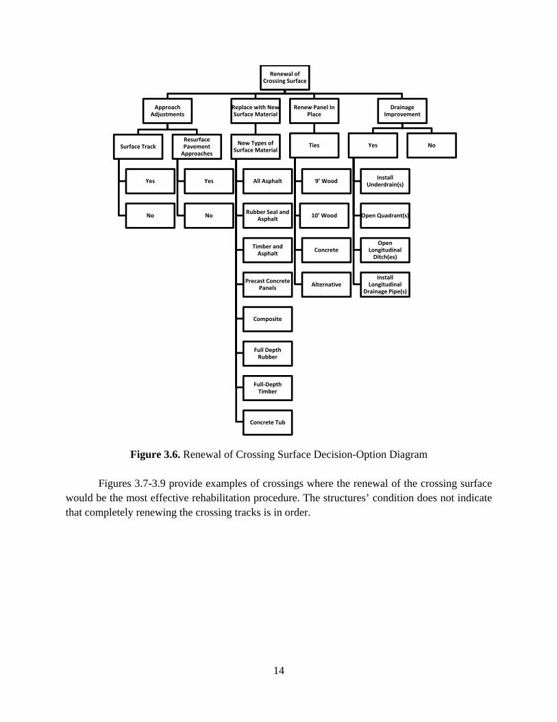
Figure 3.6 contains a decision-option diagram that outlines the primary considerations for crossing surface renewal; it provides a list of potential tie and crossing surface replacements.
14
Figure 3.6. Renewal of Crossing Surface Decision-Option Diagram
Figures 3.7-3.9 provide examples of crossings where the renewal of the crossing surface would be the most effective rehabilitation procedure. The structures’ condition does not indicate that completely renewing the crossing tracks is in order.
Renewal of Crossing Surface
Approach Adjustments
Surface Track
Yes
No
Resurface Pavement
Approaches
Yes
No
Replace with New Surface Material
New Types of Surface Material
All Asphalt
Rubber Seal and Asphalt
Timber and Asphalt
Precast Concrete Panels
Composite
Full Depth Rubber
Full-Depth Timber
Concrete Tub
Renew Panel In Place
Ties
9’ Wood
10’ Wood
Concrete
Alternative
Drainage Improvement
Yes
Install Underdrain(s)
Open Quadrant(s)
Open Longitudinal
Ditch(es)
Install Longitudinal
Drainage Pipe(s)
No

15
Figure 3.7. Completely Deteriorated surface.
Figure 3.8. Deteriorated surface.

16
Figure 3.9. Deteriorated all timber crossing, still smooth.
Determining Proper Surface Material for Surface Renewal
If field investigations reveal that the existing crossing surface needs replacement, the crossing’s characteristics will influence the selection of a proper surface material. The choice of crossing surface material greatly impacts overall project cost, installation time, and the future performance of the crossing. Several factors influence the choice of surface material, including:
Average Annual Daily Traffic (AADT)
Percentage Truck/Heavy Vehicle Traffic
Daily Train Traffic
Train Tonnage
Average Train Speed
The KYTC crossing inventory should be consulted for information on the crossing. After checking this resource, project managers will have a better foundation upon which to base their selection of surface material.
Types of Crossing Surfaces
This section describes surfacing materials that are the most commonly used at crossings. It also discusses under what circumstances each surface is appropriate. While the descriptions do serve as a guide for selecting crossing surfaces, the decision relies on context-dependent factors and must be determined after field investigation.

17
All Asphalt crossings can be used for low volume or rural crossings. The only material needed for this surface is asphalt, which is placed in between and on the field sides of the rails.
A Rubber Seal and Asphalt Crossing is used for medium to high volume crossings. This surface includes asphalt in the crossing’s center, rubber strips that enclose the rails, and asphalt, which is placed against the rubber on the field sides.
All Asphalt
Rubber Seal and Asphalt

18
Timber and Asphalt Crossings are also suitable crossings with medium to high volumes. For this surface, asphalt is laid in center, wood timbers are placed on both sides of the rails, and asphalt deposited against the timber on the field sides.
Concrete Panels are generally selected for crossings on high-traffic roads; this surface is created by inserting concrete panels between the rails and on the field sides. It is considered a premium surface.
Timber and Asphalt
Concrete Panels

19
Full-Depth Rubber is a type of surface that is applied to the full-width concrete surface. It is considered a premium surface generally used on high traffic highways. There is a higher material cost associated with it.
Full-Depth Timber consists of wood timbers, which run parallel to the track; they are laid between the rails as well as on their exterior. Like full-depth rubber and concrete, they are also used for high traffic volumes and are considered a premium material.
Full-Depth Rubber
Full-Depth Timber

20
Composite surfaces are similar to full-depth timber surfaces but consist of various types of finely divided waste products that are mixed with polymeric adhesives to bind the materials. They are mostly used on high volume crossings, and the cost of installation and materials is high compared those used on more common crossing surfaces.
Concrete tub crossings are used rarely compared to similar premium crossing materials. They are generally used in conjunction with high volume highways and low speed/tonnage rail lines.
Composite
Concrete Tub

21
General Guideline for Crossing Material Selection
The following table provides guidance for selecting the proper crossing surface material. Recommendations are based on train tonnage, vehicular traffic, and truck traffic; these numbers are expressed in car equivalents per day. Several other factors, as discussed above, may influence the decision on the crossing surface used. In the table “standard” encompasses more economical crossing surfaces, such as rubber seal and asphalt, all-asphalt, and timber and asphalt. “Premium” includes surfaces that are more costly and require more extensive rehabilitation when they deteriorate. Premium surfaces include concrete panel, concrete tub, full-depth timber, full-depth rubber, and composite.
RAILROAD MGT CAR EQUIVALENTS PER DAY
0-50,000 50,000-100,000 100,000+
0-20 STANDARD STANDARD PREMIUM
20+ STANDARD PREMIUM PREMIUM
*Car Equivalents Per Day = # of trucks x 100 per day + # of cars per day
Complete Renewal of Crossing Surface, Track Panel, and Underlying Support
Crossings commonly exhibit significant settlement due to the pumping of fines from the trackbed. This creates uneven, rough crossings for highway vehicles. Track settlement, in some cases, may be substantial enough to adversely impact train operations. A factor that contributes to the failure of trackbed support, when fines are removed, is damage to the underlying drainage network. Often the underlying support has insufficient load carrying capacity, which is further exacerbated by fines contaminating the ballast.
Figure 3.10 represents the decision sequence that is applied when a crossing surface, track panel, and underlying support are completely renewed. Under this scenario, all present elements are totally removed and replaced with new materials having increased and therefore adequate load-carrying properties. Also, the adequacy of the drainage should be addressed and appropriate improvements selected. Usually, this process entails assessing pavement approaches, and in many cases they will be raised to match the adjusted top-of-rail elevations of the track. The track approaches are typically adjusted vertically and elevated slightly, as the crossing area is surfaced before the new surface crossing is set into place.

22
Two critical decisions in this scenario are the selection of track support materials and the type of crossing surface. Determining the proper support materials is a vital part of rehabilitation. The quality of the support significantly affects the crossing surface’s performance. Premium crossing materials are able to compensate for poor quality support, but this comes at a much higher price. Generally, establishing quality and resilient underlying support is the most cost-effective way to improve crossing performance. Commonly used support material combinations include:
All-Granular Subballast and Ballast
Asphalt Underlayment and Ballast
All-Granular Subballast, Asphalt Underlayment, and Ballast
All-Granular Subballast, Geofabric, and Ballast
Geofabric and Ballast

23
Figure 3.10. Complete Renewal of Crossing Surface, Track Panel, and Underlying Trackbed Support Decision-Option Diagram
Figures 3.11-3.14 illustrate crossings that will require a complete renewal of the crossing surface, track panel, and underlying support. These crossings also exhibited significant settlement due to their underlying supports failing.
Complete Renewal of Crossing Surface,
Track Panel, and Underlying Support
Approach Adjustments
Surface Track
Resurface Pavement
Approaches
Four Welds Track Panel
Ties
9’ Wood
10’ Wood
Concrete
Alternative
Rail and Anchors
115/119 lb
132 lb
136 lb
Fasteners
Cut Spike
Premium
New Surface Material
All Asphalt
Rubber Seal and Asphalt
Timber and Asphalt
Precast Concrete Panels
Composite
Full Depth Rubber
Full Depth Timber
Concrete Tub
Drainage Improvement
Yes
Install Underdrain(s)
Open Quadrant(s)
Open Longitudinal Ditch(es)
Install Longitudinal Drainage Pipe(s)
No
Support Materials
Granular Subballast &
Ballast
Asphalt & Ballast
Granular Subballast &
Asphalt & Ballast
Granular Subballast &
Geofabric & Ballast
Geofabric & Ballast

24
Figure 3.11. Poor quality support.
Figure 3.12. Settled and pumping crossing, lack of support.

25
Figure 3.13. Settlement and surface deterioration.
Figure 3.14. Excessive settlement and pumping.

26
CHAPTER 4
Visual Guide to Evaluate Crossing Surface Conditions
The section provides a visual guide to facilitate readers when they inspect crossings. To aid with evaluation, this section contains images of crossing surfaces in a wide range of conditions. It includes examples of all cross surfaces that are frequently used, and grades each surface as good, fair, or poor. As with other information presented in this manual, this visual guide is not meant to be prescriptive, it is an aide that can give readers a starting point to begin field inspections. It is, therefore, just one tool that readers can take advantage of to decide how to proceed with crossing rehabilitation.
Concrete Panel – Good Condition

27
Concrete Panel – Fair Condition
Concrete Panel – Poor Condition

28
Composite – Good Condition
Composite – Fair Condition

29
Composite – Poor Condition
Full-Depth Timber – Good Condition

30
Full-Depth Timber – Fair Condition
Full-Depth Timber – Poor Condition

31
Timber and Asphalt – Good Condition
Timber and Asphalt – Fair Condition

32
Timber and Asphalt – Poor Condition
All Asphalt – Good Condition

33
All Asphalt – Fair Condition
All Asphalt – Poor Condition

34
Rubber Seal and Asphalt – Good Condition
Rubber Seal and Asphalt – Fair Condition

35
Rubber Seal and Asphalt – Poor Condition
Full-Depth Rubber – Good Condition
36
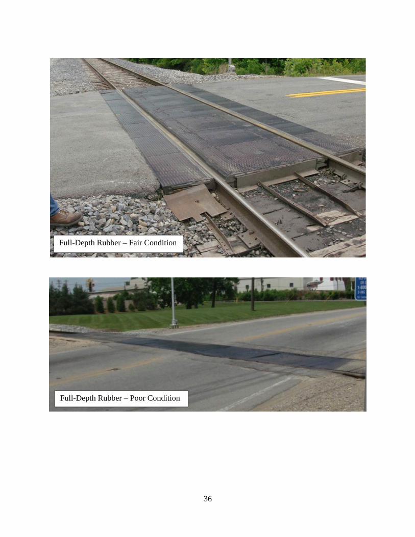
Full-Depth Rubber – Fair Condition
Full-Depth Rubber – Poor Condition

37
Concrete Tub – Good Condition
Concrete Tub – Poor Condition

38
CHAPTER 5
Rehabilitation Activities
After completing pre-rehabilitation planning and choosing a rehabilitation procedure, construction can begin. This section addresses the activities that must be undertaken during the actual rehabilitation of the crossing. For simplification, this section demonstrates the activities that would be adopted when using an asphalt underlayment. Although it would be possible to outline general principles at an abstract level, using a case study demonstrates to readers how a rehabilitation specific project moves forward. Alternatives to an asphalt underlayment were discussed earlier in this manual; the principles listed below can be used for other rehabilitation procedures.
Activities
Removal and Excavation Construction begins with the removal of the old crossing surface and track panel. Under normal conditions, the trackbed is excavated an approximate depth of 28 in. (70 cm) below the top of rail. Backhoes, hydraulic excavators, track loaders, and dozers assist with these activities. Dump trucks (either highway or hi-rail) are needed onsite to move fouled ballast and other excavated materials offsite. Compact Subgrade with Vibratory Roller (if required)
Dump and Spread Subballast A subballast layer is optional when asphalt underlayment is used. There is added benefit when both layers are used. Subballast should be dumped on top of the subgrade and spread with a backhoe, dozer blade, or loader or excavator bucket to a depth of at least six inches (150 mm).
Compact Subballast Compact the subballast using a common vibratory, steel wheeled roller.
Dump and Spread Asphalt Underlayment If included, an asphalt layer should extend 1.5-2 ft. (0.45-0.6 m) beyond the end of the ties; it should stretch a predetermined distance beyond the ends of the crossing to establish a transition zone. The recommended minimum distance for the transition zone is 25-100 ft. (8-30 m (Asphalt Institute, 1998). Backhoes, dozer blades, loader buckets, or excavator buckets can be used to spread the asphalt. Compact Asphalt Underlayment When compacting the asphalt, a standard roller, preferably a steel-wheeled, vibratory type will yield the best results. A compaction level of 95 percent is desirable, which is usually

39
achieved if compaction occurs while the mix is 200-300°F (95-150°C). After compaction, the layer of asphalt will serve as the crossing’s foundation. To facilitate asphalt drainage, leave a slight crown or side slope on the asphalt.
Dump and Spread Ballast Using the loader, dump the ballast atop the asphalt so that an 8-12 in. (200-300 mm) layer will remain after compaction. As with setting asphalt layer, spread the ballast with a backhoe, dozer blade, loader bucket, or excavator bucket.
Compact Ballast The same roller used on the asphalt and/or subballast for compaction can be used to compact the ballast. This reduces consolidation of the ballast and settlement of the crossing.
Replace Track Panel Maneuver the new track panel into place on top of the compacted ballast using the onsite equipment. If the rail has expanded to a degree that the panel will not fit, trim off the excess.
Bolt Joints Once the panel is in place, temporarily secure the new panel to the old rail using joint bars. If time permits, the rail can be welded during the track outage.
Add Cribbing Ballast Dump additional ballast into the track; this provides the necessary foundation to elevate the track, make adjustments, and fill in the cribs between the ties.
Surface, Tamp, and Broom If track needs to be raised, at this point it can be elevated.
Install Surface
Approaches Mill any repaved approaches to reduce the thickness and/or remove defects. Not all areas will require milling. Sweep the old pavement – if needed – and apply a tack coat to the surface. After completing this, paving may begin. The asphalt may be placed by truck, hand, or a paving machine. A vibratory roller can assist with compaction. If the approaches are going to be very long, the best practice is to use a paving machine.
Spray Water The final step is to spray water on the asphalt to cool it. Spraying water minimizes rutting of the new asphalt if the highway is immediately opened to traffic. This activity is normally not necessary unless the crossing will immediately handle turning highway traffic[jc1].[a2]

40
Primary Material Details Several layers of materials comprise the crossing structure. The new subgrade or existing
roadbed provides the foundation the various layers are placed on.
Asphalt The asphalt mixture used to renew a crossing is separated into two categories: 1) Asphalt for the underlayment, which is placed within the track structure (optional) and 2) Asphalt that fills trenches beside the track on the highway approaches (required) as well as asphalt for the transitional crossing surface approaches (optional). For the asphalt underlayment, a mix of paving grade asphalt and densely graded mineral aggregates, similar to that used for highway pavement applications, should be used. The maximum aggregate size is normally 1.0-1.5 in. (25-37 mm) for a typical base mix. To optimize asphalt for a highway base mix, increase the asphalt cement content by 0.5 percent.
Approximately six to eight inches (150-200 mm) compacted asphalt thickness should be laid depending upon the quality of the roadbed support. At least 0.42 ton/track ft. (1.25 metric tons/track meter) is needed. This value assumes a 12 ft (3.7 m) wide, six in. (150 mm) thick layer of asphalt, with a density of 140 lb./ft3 (2250 kg/m3).
To provide a smooth approach to the crossing, use additional asphalt mix to fill in the trenches adjacent to the track as well as to pave the highway approaches. The amount of asphalt needed depends on the crossing’s width, the depth desired for the approaches, and the required approach lengths. An asphalt surface mix meeting highway/governmental specifications is typically adequate for this application. On high-traffic highways, the use of Superpave asphalt mixes is recommended.
Ballast The ballast layer is placed on the asphalt underlayment (or granular subballast layer) to reduce the unit loading pressures. Granite or similar mainline ballast is preferable, as it does not crush and degrade as easily. When ballast is added to the top of the asphalt underlayment, the rocks should slightly penetrate the asphalt surface as this increases the shear strength across the layers. This is simple to execute when the ballast is immediately distributed and compacted before the compacted asphalt layer cools significantly.
Track Panel Replace the existing track panel that is removed from the crossing with a new pre-assembled track panel. A new panel should be sized to fit into the gap created by removing the old track panel while still allowing for some expansion of the rail before it is placed in the gap. Track panel should be composed of all new ties to provide maximum strength and extended life. The typical panel length is 80 ft. (24.3 m).
Crossing Surface The crossing surface material is based on the volume and composition of the highway traffic utilizing the crossing.

41
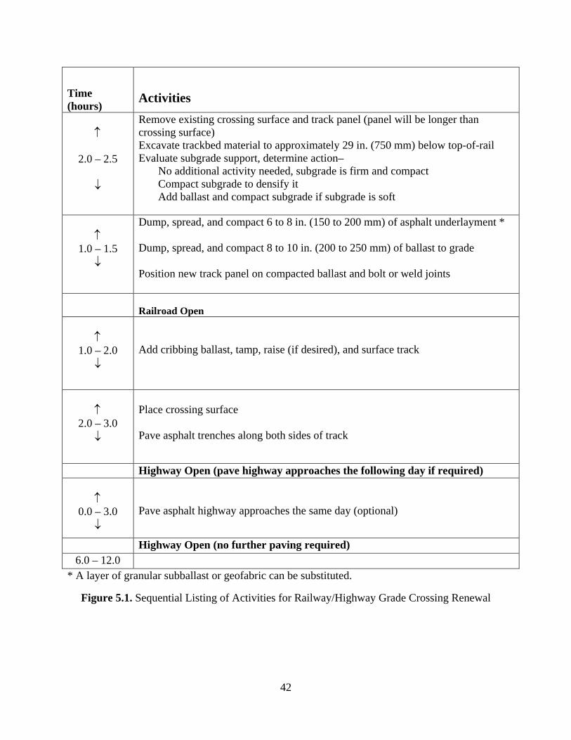
Sequential List of Activities
Figure 5.1 summarizes the rehabilitation activities discussed above using the asphalt underlayment method. The necessary activities in the rehabilitation process are listed in order, with estimates for the amount of time necessary to complete each one. This diagram may help establish temporal benchmarks for each process in the rehabilitation phase of the project. It may also inform selection of appropriate equipment and labor allocation. Figures 5.2 and 5.3 illustrate the major activities involved with the renewal of two railway/highway grade crossings.
42
Time (hours)
Activities
2.0 – 2.5
Remove existing crossing surface and track panel (panel will be longer than crossing surface) Excavate trackbed material to approximately 29 in. (750 mm) below top-of-rail Evaluate subgrade support, determine action– No additional activity needed, subgrade is firm and compact Compact subgrade to densify it Add ballast and compact subgrade if subgrade is soft
1.0 – 1.5
Dump, spread, and compact 6 to 8 in. (150 to 200 mm) of asphalt underlayment * Dump, spread, and compact 8 to 10 in. (200 to 250 mm) of ballast to grade Position new track panel on compacted ballast and bolt or weld joints
Railroad Open
1.0 – 2.0
Add cribbing ballast, tamp, raise (if desired), and surface track
2.0 – 3.0
Place crossing surface Pave asphalt trenches along both sides of track
Highway Open (pave highway approaches the following day if required)
0.0 – 3.0
Pave asphalt highway approaches the same day (optional)
Highway Open (no further paving required) 6.0 – 12.0
* A layer of granular subballast or geofabric can be substituted.
Figure 5.1. Sequential Listing of Activities for Railway/Highway Grade Crossing Renewal

43
Figure 5.2. Typical Fast-Track Crossing Renewal Operations Using Asphalt Underlayment on U.S. 25 (Main Street) in Richmond.

44
Figure 5.3. Typical Fast-Track Crossing Renewal Operations Using Asphalt Underlayment at Bull Creek in Floyd County

45
CHAPTER 6
Post-Project Administration
After completing rehabilitation, it is necessary to evaluate whether all facets of the project have been completed in the manner specified by KYTC before work commenced. Once installation is complete, any debris interfering with the crossing must be discarded or placed at a safe distance from the track. Such debris includes:
Brush, Trees, and other Vegetation
Fouled Ballast
Old Crossing Materials
Soil and Rock Any damage to the drainage system within the crossing perimeter must be repaired. Ditches and pipe inlets must be cleaned and sloped away from the crossing surface. Soon after completion, it is imperative that site inspections are conducted, for a variety of reasons. They ensure that the crossing has been completed to specifications. A qualified Cabinet member should be on hand during all work on the crossing rehabilitation. This further establishes KYTC as the authoritative body responsible for overseeing crossing rehabilitation while also promoting the use of best practices. If KYTC personnel are not present at the rehabilitation, a member of the Railroad Division should conduct an inspection of the crossing project within 15 days of the rehabilitation’s completion.
Furthermore, a follow-up inspection should be performed no less than one year following the rehabilitation. Inspection should take note of, but not be limited to, the degree of settling in the crossing, the amount of deterioration of the crossing surface, the amount of deterioration of the highway approaches, and the presence of settling and/or pumping of mud on the railroad approaches. These data would contribute to future Pre-Project Administration and standard procedural processes by objectively showing the cost effectiveness of the crossing as well as the durability of materials used and how they have responded to particular site conditions.
The importance of post-rehabilitation inspection cannot be overstated. It is critical for the projects at hand, as well as those under consideration, and should be pursued in the future.

46
ACKNOWLEDGMENTS
This research was funded by the Kentucky Transportation Cabinet through the Kentucky Transportation Center.

A-1
APPPENDIX A
Highway/Railway At-Grade Crossing Condition Evaluation Form

A-2
HIGHWAY/RAILWAY AT-GRADE CROSSING CONDITION EVALUATION
Agency _________________________________________Date_______________
Location of Crossing:
DOT Number _______________ Route Number/Street Name _________________________
County _______________________ City (specify in or near) _________________________
GPS: Latitude __________________________ Longitude______________________________
Highway Classification:
Rural Highway ____ or City Street ____; Primary ____, Secondary ____, or Collector ____
Highway Information:
Mile Point __________, ADT ____________, % Trucks _________, Haul Route (y/n)________
Railroad:
Company ____________________, Division ___________________, Mile Post ___________
Primary Limits, From __________________________ To _____________________________
Railway Line Classification:
Primary Mainline Tonnage: Heavy _____, Moderate _____, Light _____
Secondary Mainline Tonnage: Heavy _____, Moderate _____, Light _____
Branch Line ___________________________ Siding/Yard Track _______________________
Crossing:
Surface Material: Rubber Seal/Asphalt _____, Timber/Asphalt _____, Composite _____,
Concrete Panel _____, All Rubber _____, All Timber _____,
Concrete Tub _____, or All Asphalt _____
Number of Tracks _______, Number of Highway Lanes ______, Length of Crossing _______ft.
Pavement Approach Material: Asphalt _____, Concrete _____, Other ___________________

A-3
Qualitative Assessment of Roughness/Rideability of Crossing:
Check the Applicable Scale
_____ (5) Very Smooth
Almost unnoticeable at highway speeds Suggested Speed – Urban 30 mph, Rural 50 mph Comment – Exhibits new crossing appearance, Excellent condition
_____ (4) A Very Slight Bump –
Hardly noticeable by vehicle occupants Suggested Speed – Urban 30 mph, Rural 50 mph Comment – Smooth, solid, not worn, Excellent condition
_____ (3) A Bump Felt –
Not serious enough to affect the vehicle occupants Suggested Speed – Urban 30 mph, Rural 50 mph Comment – Slightly worn but solid, some roughness, Good condition
_____ (2) Noticeable Jar –
Uncomfortable but not severe, some speed adjustment for safety Suggested Speed – Urban 30 mph, Rural 50 mph Comment – Crossing loose and rough, surface area between tracks broken causing
rough ride, Fair condition
_____ (1) Very Uncomfortable –
Vehicle is noticeably jolted or shaken Vehicle definitely has to be slowed down to cross tracks Suggested Speed – Urban 10-15 mph, Rural 25-30 mph Comment – Crossing broken, rough, area between tracks pot holed, surface too high or
too low, Poor condition
_____ (0) Vehicle Severely Jolted –
A racking experience, crossing should be traversed at at speed less than 10 mph Suggested Speed – Urban 10 mph max, Rural 10 mph max. Comment – Crossing broken, ties loose, rotted or missing, rails high, low or loose, Bad
condition

A-4
Qualitative Assessment of Crossing Surface Material:
Check the Applicable Scale
_____ Excellent – Appears in new condition
_____ Good – Minor defects, still in sound condition
_____ Fair – Noticeable aging, some minor cracks
_____ Poor – Breaking apart, loose rail and crossing material
Comments ____________________________________________________________________
Qualitative Assessment of Crossing Pavement Approaches:
Check the Applicable Scale
_____ Excellent – New of nearly new condition, excellent workmanship
_____ Good – Some age, but still in sound condition
_____ Fair – Noticeable aging and wear, some minor cracks, some rutting
_____ Poor – Breaking apart, potholing, rutting
Comments ____________________________________________________________________
Highway Geometric Issues: Improve (yes or no) _____
Narrow Crossing _______________________ Pole/Post/Tree ____________________________
Vertical Hump _________________________Vertical Sag _______________________________
Major Contributor to Roughness (Yes or No) _______ Other _____________________________
Comments _____________________________________________________________________
Drainage Issues: Improve (yes or no) _____
Open Quadrant (s) __________________ Improve Transverse Drainage ___________________
Improve Longitudinal Drainage _______________________ Other ________________________

A-5
Track Support Issues: Improve (yes or no) _____
Crossing Settlement __________________Crossing Mud Pumping ________________________
Track Approach Settlement ____________ Track Approach Pumping ______________________
Other _________________________________________________________________________
Overall Assessment for Rehabilitation: (check the appropriate)
Only Adjustment/Improvements to the Highway Pavement Approaches _____
Only Renewal of Crossing Surface _____
Complete Renewal of Crossing Surface, Track Panel, and Underlying Support _____
Overall Comments:
______________________________________________________________________________
______________________________________________________________________________
______________________________________________________________________________
______________________________________________________________________________
______________________________________________________________________________
Evaluator’s Name _____________________________ Title __________________________
Company ____________________________Phone Number ____________________
Email Address ______________________________