PKP Polish Railway Lines’ investment plans >> Creating a World Class Rail Network

1
The LONDON MIDLAND and
SCOTTISH RAILWAY
RAILWAY TELEGRAPHS
AND THEIR
PROTECTION FROM POWER LINES
L. G. Warburton LMS Society Monologue No 8

2
Contents Introduction Chapter 1 Railway Company constructed cradle guards. Chapter 2 Power Company constructed cradle guards. Acknowledgements Acknowledgements South Western Electricity Board Overhead Line Manual Edmundsons Electricity Corporation Overhead Line manual. Railway Signalling & Telecommunications, Railway Gazette. Marcus Palmen. Gregory Fox. Foreward On the 25th January 1935 the 11.44 express from Manchester Central to Sheffield ran into a Central Electricity Board 33,000 volt overhead line that fell across the railway line at Cheadle Heath. At the time there was an exceptional gale that caused the earth wire to swing within arcing distance of 132,000 volt conductors nine feet above, with the result that the earth wire burned through and fell across the live conductors of the 33,000 volt line that in turn burned through and fell across the railway. There was no damage to the engine, rolling stock or signalling, and there were no complaints from passengers. LMS Works Committee Minute No.3675 prompted these few notes on the way railway telegraphs are protected from overhead power line conductors.

3
Introduction. It is hard to imagine the countryside completely devoid of overhead lines of any kind, but that was how it was in the first years of the railways of Britain. Then came railway telegraphs with the once familiar pole lines running alongside the tracks. Those of us old enough will remember the up and down movement of these wires when viewed from the carriage windows. Around the 1900s electric power companies came into existence starting in a very small way to supply electric tramways and street lamps, with any surplus supplying domestic consumers adjacent to the power station. From this small beginning power quickly spread through the larger cities and towns, fed mainly by underground cables with many municipalities running their own power stations. This led to villages adjacent to the town also receiving a supply, but with housing being more open, overhead lines were utilised to distribute the power being much more economical than underground cables. In taking electricity further a field it would not be long before it became necessary to cross a railway line with their attendant telegraph wires. There must have been much consternation about this by the railway companies and the railway inspectorate concerned with railway safety. As, should power lines fall onto the telegraphs, or track circuits the safety of the railway could be jeopardised and/or train services disrupted with the block telegraphs temporarily out of order. There are three solutions;-
1. To place the railway telegraphs underground. 2. To place the power lines underground. 3. To erect devices to guard and protect the telegraphs.
Whichever method was chosen the power company had to bear the cost and therefore the cheapest agreed option would be adopted where possible. It should also be mentioned that the problem also existed where power lines crossed roads, most of which had GPO telegraphs present up until quite recent times.. Before considering how the railway was crossed, a brief look at power line construction would be relevant. In its simplest terms a power line has a support that could be wood, reinforced concrete, steel or a lattice steel tower. The voltages are likely to be 6,600, 11,000, 33,000, 66,000, 132,000, 275,000 or 400,000ac, with the last three all being national grid transmission lines as opposed to distribution voltages. The 275 and 400kv lines did not exist in LMS days and in the mid 1970s most 132kv lines were designated a distribution voltage and virtually all lines of this voltage were passed over from the Central Electricity Generating Board to local Electricity Board control. When grid lines crossed the railway, the telegraphs were always placed underground and when low voltage lines domestic lines crossed i.e. 415/240 volts ac, the conductors were insulated. Ignoring steel towers, each pole has some form of steelwork fitted to which insulators are attached of which there are two types known as pin insulators and strain disc insulators. The former are used to simply support the conductor as it passes over the insulator, whilst the latter are used in conjunction with clamps to terminate a length of conductor. It will be seen the pin insulator simply supports the weight of the conductor, but the strain disc insulator must bear the full tension of the line. The photograph captions will point out these details. Pole spacing or span length on the distribution voltages varies between 300 feet and 450 feet depending on the conductors used, with an aluminium alloy span being less than cadmium copper, hard drawn copper or steel cored aluminium. In addition to the actual weight of the conductor itself, calculations were based on conductors having a 3/8” thick radial coating of ice.
4
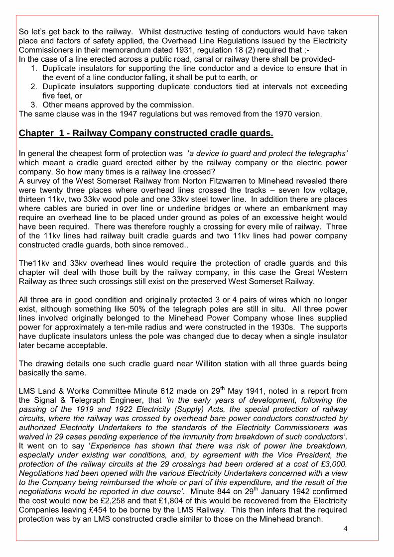
So let’s get back to the railway. Whilst destructive testing of conductors would have taken place and factors of safety applied, the Overhead Line Regulations issued by the Electricity Commissioners in their memorandum dated 1931, regulation 18 (2) required that ;- In the case of a line erected across a public road, canal or railway there shall be provided-
1. Duplicate insulators for supporting the line conductor and a device to ensure that in the event of a line conductor falling, it shall be put to earth, or
2. Duplicate insulators supporting duplicate conductors tied at intervals not exceeding five feet, or
3. Other means approved by the commission. The same clause was in the 1947 regulations but was removed from the 1970 version. Chapter 1 - Railway Company constructed cradle guards. In general the cheapest form of protection was ‘a device to guard and protect the telegraphs’ which meant a cradle guard erected either by the railway company or the electric power company. So how many times is a railway line crossed? A survey of the West Somerset Railway from Norton Fitzwarren to Minehead revealed there were twenty three places where overhead lines crossed the tracks – seven low voltage, thirteen 11kv, two 33kv wood pole and one 33kv steel tower line. In addition there are places where cables are buried in over line or underline bridges or where an embankment may require an overhead line to be placed under ground as poles of an excessive height would have been required. There was therefore roughly a crossing for every mile of railway. Three of the 11kv lines had railway built cradle guards and two 11kv lines had power company constructed cradle guards, both since removed.. The11kv and 33kv overhead lines would require the protection of cradle guards and this chapter will deal with those built by the railway company, in this case the Great Western Railway as three such crossings still exist on the preserved West Somerset Railway. All three are in good condition and originally protected 3 or 4 pairs of wires which no longer exist, although something like 50% of the telegraph poles are still in situ. All three power lines involved originally belonged to the Minehead Power Company whose lines supplied power for approximately a ten-mile radius and were constructed in the 1930s. The supports have duplicate insulators unless the pole was changed due to decay when a single insulator later became acceptable. The drawing details one such cradle guard near Williton station with all three guards being basically the same. LMS Land & Works Committee Minute 612 made on 29th May 1941, noted in a report from the Signal & Telegraph Engineer, that ‘in the early years of development, following the passing of the 1919 and 1922 Electricity (Supply) Acts, the special protection of railway circuits, where the railway was crossed by overhead bare power conductors constructed by authorized Electricity Undertakers to the standards of the Electricity Commissioners was waived in 29 cases pending experience of the immunity from breakdown of such conductors’. It went on to say ‘Experience has shown that there was risk of power line breakdown, especially under existing war conditions, and, by agreement with the Vice President, the protection of the railway circuits at the 29 crossings had been ordered at a cost of £3,000. Negotiations had been opened with the various Electricity Undertakers concerned with a view to the Company being reimbursed the whole or part of this expenditure, and the result of the negotiations would be reported in due course’. Minute 844 on 29th January 1942 confirmed the cost would now be £2,258 and that £1,804 of this would be recovered from the Electricity Companies leaving £454 to be borne by the LMS Railway. This then infers that the required protection was by an LMS constructed cradle similar to those on the Minehead branch.

5
Figure 1.
Details of a railway constructed cradle guard as illustrated in the book ‘Railway Signalling and Communications’, Railway Gazette c.1930. Figure 2.
Details a railway constructed cradle guard near Williton on the old GWR Minehead Branch.
L. G. Warburton Dwg. T1. Plate 1.

6
Portrays the Blue Anchor railway constructed cradle guard complete with backstays but without any railway telegraphs as on 17th. September 1997. The wires between the poles can be seen vertically bonded together for earthing purposes by the poles nearest to the camera with an earth wire running down the poles. It should be stated that not all railway wires were to do with communications as wires ran from out of sight signals to repeaters in the signal box to indicate the signal had operated or the flame was lit. Power circuits could also be included to trickle charge batteries for the operation of signals, points etc from supply mains, such circuits would utilize insulated wires.
L. G. Warburton. Plate 2.
Taken on 9th September 1997 this picture portrays the Minehead Power Company 11,000 volt wood pole line of triangular construction with the pole top circuit complete with the required duplicate pin type insulators and catchment bracket that earthed a conductor should it break on the span crossing the railway at Williton. The conductors which are 0.08 sq. inch steel cored aluminium are also tied together at not less that 5’ 0” centres. The top insulators are the pin type simply supporting the conductors. The line also has a “T” off fed from the top circuit via pull down fuse isolators on the lower cross-arm to the circuit on the centre cross-arm, which, being a termination has strain disc insulators and is suitably back-stayed as indeed is the span crossing the railway.
L. G. Warburton. Plate 3.

7
A railway crossing pole having strain disc insulators terminating the conductors on both sides of the cross-arm with bowes connecting the terminated conductors together via pin type insulators mounted on the top of the cross-arm. The span crossing the railway has the required duplicate insulators spaced by bridles with the conductors tied together with the catchment bracket below.
L. G. Warburton. Plate 4.
This LMS Railway constructed telegraph line guard of several spans is near Bibbington Sidings between Chapel-en-le Frith and Buxton. Several power lines are crossing at this point including a 132.000volt National Grid line with the “H” pole lines being either 66 or 33,000 volts. The train, hauled by 49392, is the 8.45am Rowsley to Adswood brought to a stand for the brakes to be pinned down. Photo. J. W. Sutherland, courtesy of Foxline Ltd.
Plate 5

8
A view of the same crossing from the opposite direction with banker 49281 on 18th June 1960.
Photo. J. W. Sutherland, courtesy Foxline Ltd.
Chapter 2 - Power Company constructed cradle guards.
It is worth noting that prior to nationalisation in 1948 vast areas of the countryside were without power. As an example, In the West Country, West Devon, Exmoor and Dartmoor had little or no power, not to mention rural areas of Somerset and Devon much nearer to large towns. Indeed out of 34,200 farms and smallholdings in the South Western Electricity Board area only 6,330 had a supply and at best about only 10% of those without power were near enough to mains to be possibly connected. Around 1950 a massive Rural Development programme was instigated to ‘Bring Power to the People’ that took almost twenty years to complete thus doing away with generators and 12v batteries for those with ‘Hornby Dublo’ model railways.

9
The reason for referring to this is to point out that taking electricity out of town to the surrounding villages meant that more railway crossings were likely, not to mention road crossings. To illustrate this point, we saw in Chapter 1 that there were three Minehead Power Company railway Crossings all within ten miles of Minehead. A survey on the eleven miles of railway between Bridgwater and Taunton on the old GWR main line revealed four 11kv cradle guards all erected after 1957. No pre-war power line was noted apart from a 33kv steel tower line erected c.1932 as part of the original National Grid. Power line conductors rarely fail – poles might break in freak storm conditions but conductors rarely break and if they did the chances of it doing so in a span crossing a railway must be more than winning the National Lottery. In fact around 1950, a delegation from the Midlands Electricity Board visited the USA to report on their system planning, live line working, system protection etc where unsurprisingly no cradle guards were erected. It was cheaper to pay for the damage to a telephone exchange or whatever than to go to the expense of building guards every time road or rail telegraphs are crossed for situations that do not occur. Notwithstanding, Britain still continued to build cradle guards until the advent of PVC, when under certain conditions either the power line conductor or the telephone wires were PVC insulated. Today one rarely sees a cradle guard over a road, as all the BT circuits are either underground, PVC insulated or in the form of a catenary cable and the cradle has been removed. On the other hand the railway cradles still exist in spite of the fact railway overhead telegraphs all now generally run in concrete troughing. Technology moves on as fibre optic communication cables are now fitted to the earth wires on national grid lines. Clearly the cost of the four pole structure as dealt with in chapter 1 would be much greater than fixing the cradle guard to the same poles that were supporting the power line and accordingly the practice of the railway providing the protection of it’s telegraphs ceased for 11 and 33kv crossings it most, if not all circumstances. Shortly after nationalisation the requirement for duplicate insulators and bridles on road, rail and canal crossings was withdrawn and the newly formed Electricity Boards instigated their own designs based on the relevant British Standard specification. The cradle guards and pole arrangements shown here represent those of the South Western Electricity Board and no doubt in other areas of the country designs would differ in detail. Board designs were replaced on the 1970s by Electricity Supply Industry standards BS1320 to which all boards would apply and which did not contain and design for a cradle guard. Summary. Low voltage 415/240volt lines – Insulated conductors. 11kv, 33kv and 66kv – Cradle guards up to c.1960. 132kv, 275kv and 400kv – Telegraphs under-grounded. It is to be hoped this unusual railway subject has proved to be of interest and so the next time you travel by train in your area, look out for power line crossings and old cradle guards and if possible take photographs as they are a dying breed. If you find any, then send the author a copy. Figure 1.

10
Portrays the South Western Electricity Board methods and criteria for both 11,000 and 33,000 volt lines. L. G. Warburton Dwg. T2. Plate 1.
Somewhere on the Somerset levels an 11,000volt ‘H’ pole to Drawing SCGA 2/16 is being erected using a falling derrick. L. G. Warburton collection. Plate 2.

11
With the poles now erected, the linesmen are binding the 4swg copper cradle rods to the 0.10 sq inch copper cradle wires using 14swg soft drawn copper wire. They are standing on a platform fixed to temporary 0.10sq. inch conductors running through line termination clamps attached to the poles. The cradle is earthed, being pre 1959, as after this date the stays would be fitted with insulators, the whole arrangement being un-earthed. The whole operation is being carried out under the watchful eye of the BR flagman as Hall class engine 4973 ‘Sweeney Hall’ speeds by hauling a fitted freight. There are ten pairs of telegraph wires involved. Not sure what the ‘elf & safety folk would think about this now? Note the trackside grass is cut and the weed free cess with the ballast having a nice clean edge.
L. G. Warburton collection Plate 3.
A SWEB constructed railway cradle to Drawing SCGA 2/15 at Huntworth near Bridgwater using 46 foot long poles of 1957 vintage with 0.10sq. inch conductors on pin type insulators and earthed as the stays are plain with no insulators. With pin type insulators a catchment bracket is required at the end of the crossarms to prevent a conductor from slipping off the crossarm should the binding of the conductor to the pin insulator fail Such an
arrangement with strain disc termination insulators is not necessary. 18th September 1997. L. G. Warburton.

12
Plate 4.
A SWEB 33,000volt heavy construction overhead line near Creech St. Michael, Taunton with a railway cradle guard utilizing 0.15 Aluminium alloy, copper equivalent conductors on ‘H’ type poles. The poles are again 46 feet long that were the longest normally used and dated 1956. L. G. Warburton Plate 5.
Shows a post 1959 cradle guard with insulated stays crossing the Kent and East Sussex Railway on 28th September 2001. This is a South Eastern Electricity Board design.
L. G. Warburton.

13
Plate 6.
Portrays the Bridgwater Main to Bowhayes Cross 33,000volt tower line crossing the A39 road at Spaxton on 1st October 1997 and since dismantled. The picture is included to show just how large cradle guards could be that could equally apply to a railway crossing.
L. G. Warburton. Plate 7.
To show such cradles were not unique to this country, this picture features a cradle guard on the Sishen to Saldanha iron ore line at Lambert’s Bay, South Africa, taken on 7th August 2002. L. G. Warburton.

14
Published by L. G. Warburton, “Adsborough Cottage”, Thurloxton, Taunton TA2 8RF, Somerset. e-mail – [email protected] L G Warburton has asserted his moral right to be identified as the Author of this work in accordance with the Copyright Designs and Patent Act 1998
This monologue belongs to a series produced by members of the LMS Society to provide a background to the activities and achievements of the LMS Railway during its existence from 1st January 1923 to 31st December 1947 Details of other publications in the series and of the wider bibliography of members of the LMS Society, refer to the Society's website
www.lmssociety.org.uk Any other requests for information should be addressed to:-