RAILWAY OCCURRENCE REPORT R97C0147 - Bureau · PDF fileRAILWAY OCCURRENCE REPORT R97C0147 ......
45
RAILWAY OCCURRENCE REPORT R97C0147 RUNAWAY/DERAILMENT CANADIAN PACIFIC RAILWAY TRAIN NO. 353-946 LAGGAN SUBDIVISION FIELD, BRITISH COLUMBIA 02 DECEMBER 1997
Transcript of RAILWAY OCCURRENCE REPORT R97C0147 - Bureau · PDF fileRAILWAY OCCURRENCE REPORT R97C0147 ......

RAILWAY OCCURRENCE REPORT
R97C0147
RUNAWAY/DERAILMENT
CANADIAN PACIFIC RAILWAY
TRAIN NO. 353-946
LAGGAN SUBDIVISION
FIELD, BRITISH COLUMBIA
02 DECEMBER 1997


The Transportation Safety Board of Canada (TSB) investigated this occurrence for the purpose of advancing
transportation safety. It is not the function of the Board to assign fault or determine civil or criminal liability.
Railway Occurrence Report
Runaway/Derailment
Canadian Pacific Railway Train No. 353-946 Laggan Subdivision Field, British Columbia 02 December 1997
Report Number R97C0147
Synopsis
On 02 December 1997, at approximately 1200 mountain standard time, Canadian Pacific Railway westward
train No. 353-946 derailed 66 cars during an uncontrolled high-speed descent on a steep portion of the Laggan
Subdivision known as AField Hill.@ The three crew members were not injured.
The Board determined that the crew was unable to control the train speed after the train was set in motion on
the steep descending grade with a depleted air brake system and a dynamic brake, which can be used to
supplement the air brake, that was not engaged. A series of inappropriate train handling decisions resulted in
the depletion of the train air brake system. Railway operating procedures did not prohibit the practice of
recharging the air brake system while descending Field Hill. The use of a pneumatic control recovery procedure
which was different than that required by the railway operating manual prevented the dynamic brake from
engaging. The locomotive pneumatic control recovery feature and the Integrated Function Display were not
designed with sufficient regard to error tolerance. Further, railway training and supervision did not ensure that
the locomotive engineer had an adequate knowledge and understanding of all aspects of the operation of the GE
AC 4400 locomotive. The performance of the locomotive engineer may have been affected by fatigue.
Ce rapport est également disponible en français.


TABLE OF CONTENTS
TRANSPORTATION SAFETY BOARD iii
1.0 Factual Information .................................................................................. 1
1.1 The Accident ................................................................................................................... 1
1.2 Operating Instructions - Field Hill .................................................................................. 4
1.3 Injuries ............................................................................................................................. 5
1.4 Particulars of the Track ................................................................................................... 5
1.5 Occurrence Site Information ........................................................................................... 5
1.6 Personnel Information ..................................................................................................... 6
1.7 Hours of Work and Rest Requirements .......................................................................... 7
1.8 Fatigue ............................................................................................................................. 8
1.9 Train Information ............................................................................................................ 9
1.10 Locomotive Equipment and Operation ........................................................................... 9
1.10.1 GE AC 4400 Integrated Function Display Screens ...................................................... 10
1.11 Pneumatic Control Recovery ........................................................................................ 11
1.11.1 Pneumatic Control Recovery Procedures ..................................................................... 11
1.11.2 Equipment Design Principles ........................................................................................ 12
1.12 Dynamic Brake Operation ............................................................................................ 13
1.13 Air Brakes Operation .................................................................................................... 14
1.14 Running Brake Test ...................................................................................................... 15
1.15 Method of Train Control ............................................................................................... 15
1.16 Train and Locomotive Inspections ............................................................................... 15
1.17 Locomotive Engineer Training ..................................................................................... 15
1.18 Experience and Supervision .......................................................................................... 17
1.19 Transport Canada Requirements ................................................................................... 17
1.20 Other Information ......................................................................................................... 18
1.20.1 Operating Bulletins ....................................................................................................... 18
1.20.2 Other Occurrences ......................................................................................................... 18
1.21 Weather Information ..................................................................................................... 18

TABLE OF CONTENTS
iv TRANSPORTATION SAFETY BOARD
2.0 Analysis .................................................................................................. 19
2.1 Introduction ................................................................................................................... 19
2.2 Train Operation ............................................................................................................. 19
2.3 Pneumatic Control Recovery and Locomotive Control System Design ...................... 20
2.4 Training and Supervision .............................................................................................. 21
2.5 Fatigue ........................................................................................................................... 22
3.0 Conclusions ............................................................................................ 23
3.1 Findings ......................................................................................................................... 23
3.2 Causes ........................................................................................................................... 24
4.0 Safety Action .......................................................................................... 25
4.1 Action Taken ................................................................................................................. 25
4.1.1 Operating Bulletins ....................................................................................................... 25
4.1.2 Operations ..................................................................................................................... 26
4.1.3 Training ......................................................................................................................... 27
4.1.4 Locomotive Design Changes ........................................................................................ 28
4.1.5 Environmental Response ............................................................................................... 28
4.1.6 Transport Canada .......................................................................................................... 28
5.0 Appendices
Appendix A - Sketch of the Track in the Occurrence Area .............................................................. 31
Appendix B - Glossary ...................................................................................................................... 33

TABLE OF CONTENTS
TRANSPORTATION SAFETY BOARD v


FACTUAL INFORMATION
TRANSPORTATION SAFETY BOARD 1
1.0 Factual Information
1.1 The Accident
Canadian Pacific Railway (CPR) train No. 353-946 (train 353), a loaded unit grain train, departed Calgary,
Alberta, Mile 0.0 of the Laggan Subdivision at 0652 mountain standard time (MST)1, travelling westward to
Field, British Columbia, Mile 136.6. The train was operated from Calgary to Stephen, Alberta, Mile 123.0,
without incident, arriving at approximately 1150. At Stephen, the track begins a 13.5-mile descent of
approximately 1,250 vertical feet to Field, Mile 136.6 (see Appendix A).
At Mile 125.1, the crew observed an AAdvance Clear to Stop@ signal indication which means AProceed, next
signal is displaying Clear to Stop, be prepared to stop at second signal.@ The next signal was at the east switch
at Partridge, at Mile 126.8, and the second next signal was at the west switch at Partridge, at Mile 128.7.
The maximum permissible speed between Stephen and Field is 20 mph with a restriction of 15 mph between
Mile 125.7 and the east switch at Partridge, Mile 126.8.
1 All times are MST (Coordinated Universal Time (UTC) minus seven hours) unless otherwise stated.
At the east station mile sign, Partridge, Mile 125.8, the recorded train speed was 14 mph, with throttle in power
and a minimum (seven pounds per square inch (psi)) brake pipe pressure reduction. A CPR special instruction
required a supplementary (i.e. additional) brake application at this location. The purpose of this instruction is to
encourage the amount of air brake application to be balanced against the grade so that a stop at any location
between Mile 125.7 and Field can be made to enable subsequent movement without releasing the brakes. This
brake application was not performed (see Section 1.13 for an explanation of the train air brakes operation).

FACTUAL INFORMATION
2 TRANSPORTATION SAFETY BOARD
As the train approached the east switch at Partridge, travelling at 25 mph, the crew observed a AClear to Stop@
indication that required them to prepare to stop the train at the next signal, at the west switch at Partridge (Mile
128.7). The train was still accelerating past the east switch in full dynamic braking (DB)2 with a minimum
brake pipe pressure reduction when the locomotive engineer made a full service brake application. The
conductor stated that he was aware that the train speed was approximately 10 mph higher than the authorized
15 mph when the train was approaching the east switch, but he did not take any corrective action because he
felt that the locomotive engineer had the train under control. Because the train slowed more than anticipated,
the locomotive engineer gradually decreased DB application and advanced the throttle to pull the train
westward to clear the east switch. However, the full service brake application caused the train to stall at
Mile 128.1, with the rear of the train just clear of the east switch, and the head end of the train about 4,000 feet
from the west switch. Since the signal at the west switch was not visible from this location, the locomotive
engineer decided to move to a point where the crew could observe the signal. The descending grade at this
location was 2.2 per cent. The locomotive engineer was aware that an eastward train was approaching the west
switch to take the siding at Partridge, but had not yet arrived. He placed the combined controller in dynamic
brake and released the train brakes. The speed of the train increased rapidly to 19 mph approaching the west
switch. After a series of ineffective service brake applications, starting at 5.6 mph with full DB applied, the
locomotive engineer initiated an emergency brake application and stopped the train with the lead locomotive
approximately 500 feet east of the signal.
When an emergency brake application occurs, a pneumatic control (PC) switch operates automatically to reduce
the locomotive to idle and nullify power and DB, effectively placing the locomotive in neutral. The purpose of
this feature is to ensure that the locomotive is not energized while the train brakes are in emergency and before
the train has been brought to a stop. A white indicator light on the locomotive Integrated Function Display
(IFD) displaying APCS Open@ shows that the PC switch has been activated. The PC switch will not reset until
after a 60-second delay has elapsed and then only through a specific locomotive control sequence. When the
locomotive engineer initiated the emergency brake application, the 60-second delay was triggered. The
60-second delay is the time required to ensure that brake pipe vent valves on each car of the train have reset and
the cars are ready to be recharged.
2 The dynamic brake is a locomotive braking system that uses the locomotive traction motors to retard the
rotation of the locomotive drive axles and can be used alone or in conjunction with the train air brake system.

FACTUAL INFORMATION
TRANSPORTATION SAFETY BOARD 3
After the train stopped, and while waiting for the eastward train to clear the west switch, the locomotive
engineer and the conductor discussed their options with respect to recovering from the emergency brake
application and how they should proceed down the steep grade. They realized that the train air brake system
was likely depleted. A trainman trainee was on the locomotive but did not take part in this discussion. The
options discussed included whether to apply retainers3 or hand brakes
4, or to release the train brakes and
recharge the air brake system while moving, using DB to control speed. Although they had just used an
emergency brake application to stop their train because full DB and supplemental service brake applications
could not control the speed, they jointly decided to take the latter option. It was their belief that the two
locomotives, equipped with powerful extended-range DB, could control the train speed while the air brake
system recharged. They had used this procedure on previous occasions without problems and they did not
believe that the weather conditions were likely to degrade train brake response. They also believed that the
curves in the track ahead would have a retarding effect on their train. In addition, the conductor had a train
line-up list, which led them to conclude that they would not be required to meet any other trains between
Partridge and Field, Mile 136.6.
With the train still in an emergency brake application, and after approximately six minutes had elapsed on the
IFD, the locomotive engineer moved the throttle/DB handle (combined controller) from idle to the ADB
applied@ zone. When the signal at the west end of Partridge displayed AClear,@ he moved the train automatic
brake handle from emergency to release. Although CPR=s General Operating Instructions (GOI), which are not
equipment-specific, required that the combined controller remain in the idle position, it was a common practice
to place the combined controller in the ADB applied@ zone before releasing the train brakes when recovering PC
on General Motors (GM) locomotives and it did not adversely affect PC recovery or DB operation. However,
the locomotive being operated was a General Electric (GE).
The locomotive engineer interpreted a slight increase in engine speed to mean that DB was engaging. He
recalled that he had waited for the 60-second countdown indicator light (located in the air brake message
window on the IFD screen) to extinguish before releasing the train brakes and that he had interpreted this to
mean that the PC had been recovered. He did not recall seeing the white APCS Open@ indicator light
illuminated.
3 Retainer valve - A valve on all freight cars through which brake cylinder pressure is exhausted. The valve can
be manually set to retain brake cylinder pressure or restrict its rate of exhaust.
4 Hand brake - a hand-operated brake system on each rail car capable of creating the equivalent braking force of
the air brake system.
After the train brakes were released, the train accelerated to about 16 mph in about 500 feet. At this point, the
locomotive engineer began making incremental brake pipe pressure reductions totalling 26 psi, but the train
continued to accelerate. The conductor advised the locomotive engineer that he did not think that the DB was
working, in part because he could not hear the sounds normally associated with an operating DB system. The
locomotive engineer looked at his combined control lever and replied that the locomotive was in full DB. He

FACTUAL INFORMATION
4 TRANSPORTATION SAFETY BOARD
did not notice that there was no DB effort registering on the yellow DB braking effort bar on the IFD or that the
APCS Open@ light was illuminated.
The train entered the east portal of the Upper Spiral Tunnel (Mile 129.0) at about 25 mph and continued to
accelerate to approximately 46 mph when the locomotive engineer made an emergency brake application. At
about this time, 29 cars separated from the 84-car train, 16 of which derailed inside the Upper Spiral Tunnel
while passing through a 10-degree curve. The last 13 cars remained upright on the track behind the 16 derailed
cars. The head end of the train continued to accelerate.
The conductor made an emergency radio broadcast to alert anyone in the area of their runaway train. He then
spoke to the rail traffic controller (RTC) and advised him that the train was out of control.
The train continued uncontrolled, with the brakes in emergency, over the next five miles, reaching speeds of up
to 50 mph. While travelling at about 47 mph through a nine-degree curve at Mile 134.4, the two locomotives
separated from the remaining 55 cars, 50 of which derailed. The last five cars remained upright on the track.
During this time, the locomotive engineer recovered his DB function, and using DB and the independent
locomotive brake, was able to bring the locomotives under control and continue to Field.
1.2 Operating Instructions - Field Hill
The maximum authorized freight train speed on Field Hill for westward trains was 20 mph, with the exception
of a 15 mph speed restriction for trains hauling in excess of maximum tonnage (applicable to train 353) for the
assigned horsepower for the ascending grade approaching Stephen. CPR Time Table 82 special instructions
stated in part:
Maximum speed 12 to 15 mph at Stephen, maximum speed 15 mph between Stephen and public
crossing Mile 123.9 (and) Maximum speed 15 mph between Mile 125.7 and east siding switch
Partridge . . . .
In addition, these instructions stated:
If brake release is necessary, a running release must not be attempted unless the train speed allows a
full recharge of braking system. A stop must be made to recharge braking system if brakes released
under adverse weather conditions.

FACTUAL INFORMATION
TRANSPORTATION SAFETY BOARD 5
When reapplying train brakes, make an initial brake application. Under adverse weather conditions,
train brakes must be reapplied as quickly as practicable after commencing movement to maintain
conditioning of equipment. This application must be made before using dynamic brake . . . .
A supplementary reduction (2-4 psi) must be made before passing east station mile sign Partridge . .
. . Dynamic braking and/or additional supplementary reductions will be used to balance the train
through to Field. Stopping at any location between Mile 125.7 and Field should be made to enable
subsequent movement without releasing brakes.
1.3 Injuries
The crew members were not injured.
1.4 Particulars of the Track
The portion of the subdivision from Stephen to Field, known as Field Hill, is single main track, with two
designated sidings. The average descending grade is 2.2 per cent5 in the westward direction. There are sharp
curves and several tunnels, including two spiral tunnels (see Appendix A).
The track is comprised of 136-pound continuous welded rail, crushed rock ballast, with steel ties in the tunnels
and wood ties on open track.
The track is normally inspected a minimum of two times per week. The last track inspection before the
derailment was carried out on the morning of the accident. There were no deficiencies noted during this
inspection at the two derailment locations.
The track is designed for a maximum operating speed of 20 mph.
1.5 Occurrence Site Information
The 16 derailed cars at the first derailment site completely blocked the Upper Spiral Tunnel. At the second
derailment site (Figure 2), cars were scattered down the steep embankment that sloped towards the Kicking
Horse River.
About 1,500 feet of track was destroyed in the Upper Spiral Tunnel, and 1,000 feet at the second derailment
site. Sixty-four of the 66 derailed grain hopper cars were destroyed. Approximately 10,200 tons of grain was
spilled, about 9,000 tons of which was recovered.
5 A grade of 1.8 per cent and greater is considered to be a mountain grade.

FACTUAL INFORMATION
6 TRANSPORTATION SAFETY BOARD
1.6 Personnel Information
The crew consisted of a conductor, a locomotive engineer and a trainman trainee. The trainee was making his
first road trip. The conductor and locomotive engineer met the qualifications for their respective positions and
met fitness and rest requirements.

FACTUAL INFORMATION
TRANSPORTATION SAFETY BOARD 7
The locomotive engineer=s experience consisted of working as a trainman/conductor based in Medicine Hat
from 1983 to 1988. In 1988, he entered the locomotive engineers training program, but was unsuccessful in
completing the basic training. He returned to work as a conductor, operating mostly on the Laggan Subdivision
until re-entering the locomotive engineers program at Calgary in October 1995. He successfully completed the
training program and qualified as a locomotive engineer in June 1996. After qualification, he was off duty for
five months. When he returned to work, he worked as a spare locomotive engineer when an assignment was
available, otherwise he worked as a conductor on the Laggan Subdivision. He had about one year=s experience
as a spare locomotive engineer.
The locomotive engineer was working as a spare at his home terminal (Calgary), and had a duty window6 from
1900 to 0700. The night of 30 November 1997, he slept from 2230 to 0700 the next morning. At 2100, 01
December 1997, after having rested for 2.5 hours, he was called to report for duty at 2300 and was off duty at
0300 on 02 December. Local calling practices permitted a locomotive engineer either to work another tour of
duty after a Ashort turn@7 (provided he met rest and maximum hours of duty requirements) or to book rest. At
0330, 02 December, the locomotive engineer accepted a call for his second tour of duty to commence at 0530
to operate train 353 from Calgary to Field. Since he had been off duty for about 48 hours previous to the short
turn, he took a second tour of duty. Had he not taken the assignment, he could have booked rest after the short
turn and still retained his position on the spare board on the expiration of his rest. When the accident occurred,
the locomotive engineer had slept approximately 2.5 hours in the previous 29 hours.
The conductor had worked the last four years on the Laggan Subdivision. He qualified for the position of
conductor in January 1978. His previous experience consisted of working as a yard helper and yard foreman in
Alyth Yard for 22 years. The conductor was not trained or qualified as a locomotive engineer.
The conductor had a duty window from 0500 to 1500 and had been off duty about 48 hours before this
assignment. He had a good night of sleep on 30 November and he slept about five hours before he received his
call at 0330, 02 December 1997, to commence work at 0530 to operate train 353 from Calgary to Field.
1.7 Hours of Work and Rest Requirements
Maximum hours of service requirements are applicable to railway operating employees in any class of train
service. These requirements specify that no employee shall be on duty in excess of 18 hours in a 24-hour
period; the maximum time on duty in a single tour of duty is 12 hours, and 16 hours in case of work train
service or in case of emergency.
6 A duty window is a designated work period within 24 hours when the employee must be available to accept
work assignments. Duty windows were instituted as a fatigue countermeasure subsequent to the CANALERT >95 study.
7 A short turn is usually in proximity to the home terminal, is shorter in duration than a minimum day (8 hours
or 100 miles) and allows the locomotive engineer to retain his or her position on the spare board.

FACTUAL INFORMATION
8 TRANSPORTATION SAFETY BOARD
Mandatory time off-duty requirements apply only to employees who are called from an employee pool and do
not otherwise have a regularly scheduled assignment or to employees who are called into pool service from
other classes of train service. Employees covered by these requirements who have been on duty in excess of 10
hours will not be required to go on duty in pool service for at least 8 hours.
The spare board was split into two 12-hour segments, from 0700 to 1859 and 1900 to 0659. Employees on the
spare board are required to protect one of these two windows but are not called during the other. The intended
purpose of this arrangement was to guarantee employees the opportunity to obtain sufficient rest. Under this
arrangement, the locomotive engineer had the right to book 18 hours of personal rest at his home terminal.
1.8 Fatigue
Research has shown that performance on cognitive and mental problem solving, vigilance and communication
tasks shows a 30 per cent decrement after 18 hours of wakefulness. After 48 hours, a 60 per cent decrement was
indicated. Performance degradation, or impairment, is progressive, becoming worse as time awake increases.8
Fatigue can lead to slowed reactions to normal or emergency stimuli. It takes longer to perceive, interpret,
understand and react to objects and events. Fatigued operators may take procedural shortcuts that they would
not consider when they are alert because they do not recognize an increasing level of risk. People are poor
judges of their own alertness or fatigue levels. AIndividuals (especially sleepy individuals) do not reliably
estimate their alertness and performance.@9
Fatigue in the railway industry has been managed by a combination of disciplinary action and regulations
specifying mandatory off-duty time and maximum on-duty time. As well, collective bargaining agreements
cover maximum on-duty time requirements, and locomotives are equipped with automated vigilance devices. In
response to a directive from Transport Canada (TC) to develop a plan to reduce the risk of train crew fatigue,
Canadian railways and the Brotherhood of Locomotive Engineers (BLE) established a joint labour-management
steering committee and, with expert assistance, developed, implemented and tested a comprehensive Alertness
Assurance Process outlined in a report entitled CANALERT >9510.
On 27 April 1997, CPR and the BLE signed a memorandum of understanding (MOU) that implemented duty
windows for pool locomotive engineers on the Brooks and Laggan subdivisions.
In April 1997, the locomotive engineer on this assignment had received Canalert Lifestyle Training. This
training was offered to all Calgary operating employees working on the Brooks and Laggan subdivisions.
8 R.G. Angus et al., ASustained Operations Study: From the Field to the Laboratory,@ Why We Nap: Evolution,
Chronobiology and Functions of Polyphasic and Ultrashort Sleep, ed. C. Stampi (Boston: 1992), pp. 217-241.
9 M. Rosekind et al., Crew Factors in Flight Operations X: Alertness Management in Flight Operations, NASA
Technical Memorandum DOT/FAA/RD-93/18, NASA Ames Research Center, 1994.
10 CANALERT >95 Phase II, Circadian Technologies Inc., May 1996.

FACTUAL INFORMATION
TRANSPORTATION SAFETY BOARD 9
1.9 Train Information
The train was powered by two GE AC 4400 locomotives and consisted of 84 loaded grain hopper cars. It was
approximately 5,120 feet in length and weighed about 11,350 tons.
1.10 Locomotive Equipment and Operation
GE AC 4400 locomotives were put in service by CPR in 1995. Before 1995, CPR=s fleet mainly comprised
GM-manufactured locomotives, primarily the GM SD40-2F and SD40-2 type.
The GE AC 4400 locomotive air brake control is electronic/pneumatic with microcomputer control; the GM
SD40-2F and SD40-2 locomotives air brake controls are mechanical/pneumatic.
CPR=s SD40-2 and SD40-2F (9000 series) locomotive fleet was equipped with locomotive engineer control
stands of three different configurations. The earlier SD40-2 models had a GM Electro-Motive Division (EMD)
control stand that used a single throttle lever, or combined controller, to control power and dynamic brake.
Later models used an Association of American Railroads (AAR) control stand that had separate control levers
for power and dynamic brake operation. The SD40-2F (9000 series) has a control console (desk type) with a
combined power/dynamic handle on a master controller similar to that on a GE AC 4400 locomotive (see
Figures 3 and 4).

FACTUAL INFORMATION
10 TRANSPORTATION SAFETY BOARD

FACTUAL INFORMATION
TRANSPORTATION SAFETY BOARD 11
1.10.1 GE AC 4400 Integrated Function Display Screens
The GE AC 4400 locomotives, unlike the GM fleet, are equipped with liquid crystal IFD screens that display
multiple locomotive and train functions. The IFD integrates many of the locomotive control indicators that were
previously displayed on a number of dials and gauges at various locations accessible to the locomotive
engineer.
The IFD uses digital and analog displays with a combination of colours, flashing and steady indications for
various locomotive functions. The indicator for PC operation is illuminated steady white with the label APCS
Open@ in the middle of the light (see Figure 5). The braking effort bar (yellow) and tractive effort bar (green)
are shown on the same screen. The IFD was configured in accordance with the AAR Manual of Standards and
Recommended Practices for locomotive system integration.

FACTUAL INFORMATION
12 TRANSPORTATION SAFETY BOARD

FACTUAL INFORMATION
TRANSPORTATION SAFETY BOARD 13
Locomotive functions on most GM SD40-2F and SD40-2 locomotives are displayed by lights and gauges at a
number of locations within the cab (see Figure 4). The PC light is shown in red on most GM locomotives.
1.11 Pneumatic Control Recovery
1.11.1 Pneumatic Control Recovery Procedures
CPR=s General Operating Instructions (GOI) for recovering the PC were the same for GE and GM locomotives.
To recover the PC following an emergency brake application, Section 15 stated in part:
(i) Ensure the throttle [combined controller] is in IDLE position;
(ii) Place the automatic brake valve handle in EMERGENCY position; and
(iii) Wait 60 seconds, then return the automatic brake valve handle to the RELEASE position,
pausing briefly in the HANDLE OFF position.

FACTUAL INFORMATION
14 TRANSPORTATION SAFETY BOARD
On GM SD40-2F locomotives, the PC will recover when the combined controller is placed anywhere in the DB
operating zone, provided the 60-second time delay has elapsed and the automatic brake handle is returned from
the EMERGENCY position to the RELEASE position, after pausing briefly in the HANDLE OFF position. The
PC indicator light extinguishes and both power and DB are re-established.
On GE AC 4400 locomotives, the PC will not recover with the combined controller in the DB zone; however,
the automatic brake will release once the 60-second time delay has elapsed and the automatic brake valve
handle is returned from the EMERGENCY position to the RELEASE position, after pausing briefly in the
HANDLE OFF position. The APCS Open@ indicator light on the IFD will remain illuminated as a status
indication. There is no alarm to indicate that access to power and DB has not been restored. To recover PC, it is
then necessary to move the combined controller briefly into DB SET-UP or IDLE.

FACTUAL INFORMATION
TRANSPORTATION SAFETY BOARD 15
1.11.2 Equipment Design Principles
It is an accepted principle of design that equipment should be intrinsically safe; i.e., where possible, the design
should not allow an error to result in an accident. This principle is known as error tolerance. To do this, an
understanding of the causes of error is developed, and the equipment is designed to minimize those causes.
Interlocks are often employed to ensure that an action does not occur inadvertently or out of sequence.
Furthermore, errors that are made should be visible and reversible; i.e., it should be readily apparent that an
error has been made, and it should be clear how to undo that error. Compelling visual or audible alarms are
employed to draw the attention of the operator to the exact nature of the error. Finally, administrative controls,
such as rules, regulations and general operating instructions, can be used to reduce the likelihood of error in
situations where the design does not alert the operator to an error.
Mode errors develop in situations where a control has more than one function associated with it. A mode error
is said to have occurred when an operator=s knowledge and understanding of the status of the system is
erroneous. The resultant problems are typically relatively difficult to manage because of the lack of awareness
of the relationship between the problem and the mode state.
1.12 Dynamic Brake Operation
The DB system is designed to be used as a supplementary braking system, including but not limited to control
train speed on long descending grades. Because the braking force is concentrated at the locomotives, DB must
be gradually applied and released to regulate train slack. It can be used alone or in conjunction with the train air
brakes and operates by electrically converting the traction motors of a moving locomotive into electric
generators which act to retard the driving axles of the locomotives to supply a retarding force. The energy
generated is converted into heat through resistors known as DB grids. While in DB, it is common for engine
RPM to increase above idle, to power blowers that assist in cooling the DB grids.
There are two types of dynamic brakes, the standard and the extended range. The extended-range DB develops
its maximum retarding force between 6 mph and 23 mph, while the standard DB is largely ineffective below 10

FACTUAL INFORMATION
16 TRANSPORTATION SAFETY BOARD
mph and develops its maximum retarding force at 23 mph. Once the maximum DB is reached, the retarding
force decreases gradually as the speed increases.
Most GM locomotives in use on CPR are equipped with a standard DB whereas the GE AC 4400 locomotives
have the extended-range DB.
A review of the performance of the two GE AC 4400 locomotives by the locomotive manufacturer, given the
weight of the train and the physical characteristics of the track, revealed the following:
- two GE AC 4400 locomotives can generate a maximum of 156,000 pounds/feet of DB force;
- by comparing the calculated versus the observed acceleration rates, it appears that the train air brakes were
providing approximately 185,000 pounds/feet of braking force; and
- even if maximum DB force was available, the combined braking force of DB brake and air brake would
have been less than that required to control the train at maximum track speed.
1.13 Air Brakes Operation
The air brake system is the primary means of controlling speed and stopping a train. Every car is equipped with
an auxiliary and emergency air reservoir. The auxiliary reservoir provides stored air for normal brake
applications while the emergency reservoir provides additional air for emergency braking. Both reservoirs are
connected through control valves and recharging is directed through the brake pipe from the locomotives.
Control valves on individual cars and locomotives respond to changes in brake pipe pressure. A reduction in
brake pipe pressure causes the control valves to direct air from the auxiliary air reservoirs to the brake cylinders
which apply the train brakes. The level of braking is directly proportional to the amount of reduction of brake
pipe pressure through the automatic brake valve.
In the event of a rapid reduction in brake pipe pressure, either through a breech in the brake pipe or an
operator-initiated opening of an emergency valve, the control valves direct air from both the auxiliary and
emergency reservoirs to the brake cylinders. The emergency reservoirs are slightly larger than the auxiliary
reservoirs. This additional volume increases brake cylinder pressure during an emergency brake application.
When an emergency brake application is released, the control valve on each car connects the auxiliary reservoir
and brake cylinder air to the brake pipe, assisting in quick build up of brake
pipe pressure. In this condition, with the general state of charge of the individual brake system on each car
much lower than is normal, air brakes will release at a significantly lower brake pipe pressure. The required
practice when reapplying the air brake shortly after a release would be to reduce the brake pipe pressure 6 to
7 psi below the rear-end brake pipe pressure. The locomotive engineer did not adhere to this practice. He
recalled that the rear-end brake pipe pressure was 50 psi before he released the emergency brake at the west end
of Partridge.
The GE Operating Manual for CPR AC 4400 Locomotives states:

FACTUAL INFORMATION
TRANSPORTATION SAFETY BOARD 17
WARNING : STOPPING HAZARD. Under no circumstances should a train be permitted to continue in
operation if the brake pipe pressure falls below 45 psi. If this situation occurs, the train must be stopped,
and the brake pipe recharged to the railroad particular setting. Failure to comply with this warning may
result in the inability to control or stop the train.

FACTUAL INFORMATION
18 TRANSPORTATION SAFETY BOARD
CPR Operating Manual, Section 16, Item 3.5 (Use of Automatic Brake Valve) states:
Should locomotive brake pipe pressure be reduced below 48 psi during service brake application, the train
must be stopped and brake pipe system recharged.
CPR did not have specific instructions for Field Hill requiring that the trains which have had an emergency
brake application remained stopped until the brake system had been recharged.
1.14 Running Brake Test
CPR Prairie District Time Table 82 Special Instruction Item 1 required that a Arunning brake test@ (a test of
brakes made on a moving train to ascertain that the brakes are operating) be made between Mile 112.0 and Mile
113.0. This test was to ensure that the brakes were operating properly before reaching the steep descending
grade west of Stephen. It was not performed by the train crew. The locomotive engineer recalled that he had
successfully used the train brake numerous times before that point and therefore he did not think that a test was
necessary.
1.15 Method of Train Control
The method of train control on the Laggan Subdivision is the Centralized Traffic Control System (CTC),
authorized by the Canadian Rail Operating Rules (CROR), and supervised by an RTC in Calgary.
1.16 Train and Locomotive Inspections
The two locomotives had been inspected at Calgary with no problems noted. However, the incoming operating
crew members advised the outgoing crew members of an intermittent flashing light on the display of the Train
Information and Braking System (TIBS) on the lead locomotive, but they did not consider this problematic and
that the DB cut-out switch seal was broken on the trailing locomotive, but the switch was on. When tested, the
DB functioned normally. A pull-by inspection of the train was performed on departure and no problems were
noted.
1.17 Locomotive Engineer Training
CPR=s locomotive engineer training consisted of classroom training, familiarization trips, and 16 weeks of
on-the-job training. Additional time was given for the on-the-job training, if necessary.

FACTUAL INFORMATION
TRANSPORTATION SAFETY BOARD 19
The training program covered the following subjects:
$ safety and accident prevention;
$ locomotive operation and troubleshooting;
$ train and locomotive air brake systems;
$ safety and general rules;
$ operating rules;
$ air brake rules;
$ remote locomotive operation; and
$ train handling instructions, fuel conservation and track/train dynamics.
Following the classroom instruction, the trainees were assigned to work with a certified locomotive engineer
instructor for familiarization training. This familiarization training consisted of riding locomotives and
observing locomotive and train operations from a locomotive engineer=s point of view. Upon completion of
familiarization training, trainees returned to the classroom for a review of rules, mechanical and air brake
training. Written examinations were administered approximately 16 weeks after the initial training began and
are intended to test students on long-term retention during the learning process. A passing grade of not less than
90 per cent for rules examinations and not less than 85 per cent for all mechanical examinations was required
by CPR.
The final 16 weeks of on-the-job training consisted of the trainee being assigned to various certified locomotive
engineer instructors so experience could be obtained on different types of equipment and train movements. It
was expected that this on-the-job training would expose the trainee to a variety of train handling situations and
techniques. A trained locomotive engineer must be prepared to operate a variety of locomotives in road,
switcher and yard service. However, railway companies in Canada do not issue any type of certification card
that indicates whether the locomotive engineer has received training and demonstrated proficiency on a
particular type of locomotive.
When CPR introduced the GE AC 4400 locomotives in 1995, certified locomotive engineers were given a
four-hour transition course outlining the operating procedures for these locomotives.
After the transition training in 1995, GE AC 4400 locomotive training was included in the regular locomotive
engineer training program. This portion of the training was approximately three hours in duration. The training
covered the operating characteristics of the DB function and the recovery procedures after emergency and
penalty brake applications. This training did not specifically identify the circumstances under which an
emergency brake application could be released without recovering the PC on GE locomotives, as this feature
was not generally known to railway instructors before the occurrence. The locomotive manufacturer indicated
that the locomotives were built to design specifications set by the railway, including those for the PC recovery
feature. CPR advises that it never issued specifications to GE on how the PC recovery system was to work and
that this was GE=s design which CPR accepted without the knowledge that it worked differently than other
locomotives. However, the PC recovery system on the GE locomotive functioned as prescribed in CPR=s GOI
(quoted in part in section 1.11.1 of this report), while most other locomotives did not require strict adherence to
the approved method of PC recovery. According to the locomotive engineer, during classroom training, he

FACTUAL INFORMATION
20 TRANSPORTATION SAFETY BOARD
received no structured hands-on training on the use of the IFD and was given five minutes to familiarize
himself on a desktop simulation of the IFD.
The locomotive engineer completed 127 job-training trips, 11 of which involved GE AC 4400 locomotives and
included 3 trips westward and 5 trips eastward on the Laggan Subdivision. He completed an additional 28 trips
westward and 20 trips eastward on the Laggan Subdivision with other types of locomotives. Performance
evaluation reports submitted by locomotive engineer trainers ranged from Aas required@ to Aexcellent.@
1.18 Experience and Supervision
During the six months before this occurrence, the locomotive engineer had operated 41 trains on the Laggan
Subdivision, 25 of which were westward movements. Only one train had been powered by GE AC 4400
locomotives. All of the other trains were equipped with GM locomotives.
CPR has a policy that requires that the performance of locomotive engineers, conductors, yard masters, and
RTCs be evaluated at least once per year (Conducting and Reporting Efficiency Tests, Form 200). The
proficiency tests are performed by superintendents, operating officers, engineering officers, and supervisors
from the engineering and operating departments. However, at no time after he was certified as a locomotive
engineer in June 1996 had the performance of this locomotive engineer been evaluated, nor was there an
efficiency performance test11 made by supervisors.
1.19 Transport Canada Requirements
TC requires that a locomotive engineer obtain a railway company-determined overall post-training mark of at
least 80 per cent in the following subjects in order for the employee to maintain status as a locomotive engineer
or conductor and that such tests be taken at intervals not exceeding three years:
$ Canadian Rail Operating Rules;
$ railway radio regulations;
$ dangerous goods handling;
$ train marshalling;
$ air brake systems and tests;
11 Efficiency performance tests are random evaluations of an employee while on the job.
$ locomotive operation;
$ train handling; and
$ freight car and train inspection.
Candidates must also demonstrate competency in performing practical train operating duties to railway
instructors and examiners.

FACTUAL INFORMATION
TRANSPORTATION SAFETY BOARD 21
TC inspectors ride trains and audit railway training programs for compliance to the qualification standards.
Although the qualification requirements specify broad categories for railway operating employee qualification,
they do not prescribe the specific nature of training required. These are matters considered by TC to be the
responsibility of the railway company.
1.20 Other Information
1.20.1 Operating Bulletins
On 01 December 1997, the day before the accident, the railway had issued an Operating Bulletin identifying a
potential problem with GE AC 4400 locomotives on Locotrol IV-equipped trains. The bulletin indicated that
the nature of the problem had not been conclusively determined, but that, during attempted PC recovery, train
brakes had begun to release before actual PC recovery. Due to the time when the crew came on duty and the
distribution of the bulletin, it was not available to the crew of train 353 at the location where they came on
duty.
1.20.2 Other Occurrences
On 13 April 1996, a freight train handling 112 cars travelled uncontrolled between Mile 128.9 (Upper Spiral
Tunnel) and Field, reaching a speed of 34 mph. There was no derailment and no one was injured as a result of
this incident (TSB report No. R96C0086).
On 02 January 1998, a similar incident occurred on Field Hill when a 112-car freight train travelled
uncontrolled between Mile 128.9 and Field, reaching a speed of 42 mph. There was no derailment and no one
was injured as a result of this incident (TSB occurrence No. R98C0001).
1.21 Weather Information
The temperature was minus 13 degrees Celsius. The skies were clear. The wind was calm.

ANALYSIS
22 TRANSPORTATION SAFETY BOARD
2.0 Analysis
2.1 Introduction
This occurrence followed the uncontrolled train movement of 13 April 1996 investigated by the TSB.
Subsequent to this occurrence, an uncontrolled train movement occurred at this location on 02 January 1998.
In view of the continuing difficulty associated with operating trains safely down Field Hill, this analysis will
focus on the following issues:
$ train operation;
$ PC recovery and locomotive control system design;
$ training and supervision; and
$ fatigue.
2.2 Train Operation
Railway operating procedures provided some guidance for train operation from Stephen to Field, specifically on
the manner of braking to be used in preparation for and during the descent of Field Hill. By not making the
recommended supplementary brake application at the east station mile sign for Partridge, the locomotive
engineer allowed the train to accelerate above the required speed. This necessitated the use of excessive
amounts of air brake to gain control of the train, led to the depletion of the service brake air supply and
ultimately resulted in an undesired stop or stall of the train. The decision to release the brakes from this location
was questionable. Since the opposing train had not yet cleared the siding, another stop at the west end of
Partridge was foreseeable. Whereas by waiting until the opposing train had cleared the siding, it is probable that
train 353 would have averted the requirement for that stop.
When the train brakes were released from the full service application, the combined controller was in the ADB
applied@ zone. This did not adversely affect DB function because the PC was not involved. The locomotive
engineer then made a series of ineffective incremental brake applications. The required practice when
re-applying the brake shortly after a release is to first reduce brake pipe pressure at least 6 to 7 psi below the
brake pipe pressure reading at the rear end of the train. This was not done. When it became apparent that the
train could not be controlled in full DB with the automatic brake valve in the fully applied position, the
locomotive engineer initiated an emergency brake application, which brought the train to a stop at the west end
of Partridge. These events depleted the air in the air brake system. The state of charge of the air brake system
and the inability to stop at the west end of Partridge, with a full service brake application and full dynamic
brake, should have given the locomotive engineer another reference for the effectiveness of the DB on this
train.
In order to fully recharge the train air brake system, it would have been necessary to either apply hand brakes or
retainers. The crew decided not to apply hand brakes or retainers because they believed it would be safe to
begin descending the remainder of Field Hill controlling train speed with DB while the air brake system

ANALYSIS
TRANSPORTATION SAFETY BOARD 23
recharged. However, the locomotive engineer then followed an unapproved procedure of PC recovery that,
while functionally acceptable for GM locomotives, resulted in the release of the train brakes without regaining
DB on GE locomotives. Once the air brakes were released, the locomotive engineer presumed that DB was
functioning and did not observe the APCS Open@ light or the DB braking effort bar on the IFD. By the time he
realized that DB was not functioning, the train had accelerated to 16 mph before reapplying the air brakes. He
continued to make a series of ineffective brake applications until the train accelerated to the point where its air
brake system could not overcome the train=s inertia on the steep mountain grade. When the speed of the train
increased to a point where the design speed of the track was exceeded, the train derailed.
Applying hand brakes to hold the train stationary while recharging the brake system, or using retainers to retain
brake cylinder pressure on selected cars after the train brakes were released, would have ensured that train 353
safely descended the remainder of the hill, but would have caused significant delay to the train. Without a
procedure requiring the use of hand brakes or retainers, the locomotive engineer and the conductor relied on
their past experiences. Since it was not known that the air brakes could be released without regaining effective
DB function on these GE locomotives, the locomotive engineer did not anticipate problems. If retainers were
used and DB were fully applied, it is still possible that additional air brakes may have been required to control
the speed of the train. This was not the required PC recovery procedure, but it was the common practice on GM
locomotives.
The absence of explicit operating instructions requiring that the train brakes be fully charged before descending
Field Hill contributed to the crew=s decision to descend the hill with the air brake system depleted. This, in
conjunction with the locomotive engineer not knowing that a non-standard PC recovery method would not work
on this particular model of locomotive (GE AC 4400) and the application of a non-standard PC recovery
procedure, led to the uncontrolled movement of the train.
2.3 Pneumatic Control Recovery and Locomotive Control System Design
The locomotive engineer did not notice the APCS Open@ indication on the IFD screen. While the exact reason
for this could not be ascertained, the indicator (small white continuous light) was not a sufficiently compelling
display to the locomotive engineer to stimulate the desired reaction. In contrast, the APCS Open@ light on most
GM locomotives is red, which is a more compelling warning that the PC switch is open. There were, however,
several cues that may have falsely reinforced the locomotive engineer=s belief that the PC switch had reset:

ANALYSIS
24 TRANSPORTATION SAFETY BOARD
$ the extinguishing of the time-out message in the air brake message window on the IFD;
$ the emergency brake application release;
$ a slight increase in engine RPM after DB was selected; and
$ the sound of locomotive compressors.
In this circumstance, the locomotive engineer was confronted with an integrated display screen with more than
20 display operating parameters with which he had little experience, as compared to the more familiar
conventional analogue dials and indicator lights. The locomotive engineer=s lack of reference to the critical
indicators on the IFD illustrates his inexperience with these types of displays.
The control manipulation sequencing for PC recovery procedure employed by the locomotive engineer was
effective on GM locomotives and commonly used. However, it was not the approved procedure for either the
GM or GE AC 4400 locomotives. CPR supervisors were aware that a procedure different from that outlined in
their operating instructions was in common practice, but were not aware that this procedure, when applied to
GE locomotives, would release the air brakes but not recover PC and not restore power and DB. While the use
of the specified GOI procedure would have led to PC recovery, this aspect of the locomotive control system
design is not error-tolerant. Ideally, all locomotive systems should be in the same manner and have appropriate
countermeasures that can be taken so that a control error does not result in a potentially unsafe condition; i.e.,
release of the brakes without PC recovery.
The design of the locomotive control system allowed the locomotive engineer to release the train brakes
without immediate access to DB and power. This resulted in a mode error, in which the locomotive engineer
did not have an accurate appreciation of the operating state of the locomotive. This made the task of assessing
the problem and choosing an appropriate response relatively difficult. A more error-tolerant design, including a
more compelling display, could have precluded the release of the train brakes without PC recovery and thereby
averted this mode error.
2.4 Training and Supervision
The locomotive engineer=s lack of familiarity with the differences between the IFD screen used on GE
locomotives and the conventional instrumentation used on GM locomotives contributed to his inability to
recognize that the DB was not engaged. Although he did not know that the automatic brake would release
before PC recovery on this locomotive, a more thorough knowledge of the IFD may have led him to wait until
the APCS Open@ light extinguished before releasing the automatic brake or to notice the absence the yellow DB
amperage bar. The training offered to locomotive engineers did not ensure that they had sufficient
understanding and proficiency in the use of the IFD and in the ramifications of deviating from the required PC
recovery procedures.
The railway company introduced new technology in the form of the GE AC 4400 locomotives which interacted
with common local practice in an unanticipated and undesirable fashion. Although the crew members of train
353 did not follow required procedures, it was critical for them to understand the consequences of deviating
from these procedures. While the locomotives were built to design specifications endorsed by the railway, the

ANALYSIS
TRANSPORTATION SAFETY BOARD 25
railway accepted the manufacturer=s specifications relating to the PC recovery. Locomotive engineer trainers
were unaware that the PC recovery characteristics of the new locomotives, as described in the GOI, would not
allow the unapproved PC recovery method commonly used on GM locomotives to work, and therefore, they
were unable to apprise locomotive engineers of those characteristics. Certification, post-certification follow-up
and performance monitoring did not determine that there were gaps in locomotive engineer knowledge and
understanding of GE AC 4400 locomotives. Without a minimum standard to authorize and evaluate the level of
locomotive engineer qualifications, particularly outlining proficiency on locomotive type, locomotive engineers
can continue to be placed in a position of operating a locomotive for which they are not fully qualified to
operate.
2.5 Fatigue
When the locomotive engineer chose not to book rest at the completion of his short turn, he placed himself in a
position of potentially being on duty for 18 hours in a 24-hour period. Had he booked rest, he would have
positioned himself at the bottom of the list and lost the remuneration for the trip to Field. Although the
locomotive engineer=s work/rest cycle was within company and government requirements and he had taken the
lifestyle training on recommended sleep patterns, he had only had 2.5 hours of rest in the previous 29 hours
before this accident occurred. The system of remuneration and scheduling for locomotive engineers may
increase the risk that employees will work in a fatigued condition to avoid financial loss. While rest and
maximum duty time requirements exist, the current approach does not integrate elements such as remuneration
and scheduling into a comprehensive approach to fatigue management.
The locomotive engineer=s ability to make critical operating decisions and assess the consequences of those
decisions may have been impaired by fatigue. He made a number of decisions that were inconsistent with safe
train handling procedures, such as not making the required subsequent brake pipe reduction at Mile 125.8, and
choosing to control train speed with DB while recharging the train brakes when he had previously demonstrated
that the DB was insufficient to control train speed. The effects of fatigue on his performance may have been
exacerbated by his lack of familiarity with the GE locomotive.

CONCLUSIONS
26 TRANSPORTATION SAFETY BOARD
3.0 Conclusions
3.1 Findings
1. The locomotive engineer made a series of operating decisions that required him to make full service
brake application followed by an emergency brake application on a steep descending grade, thereby
depleting the air brake system on the train.
2. In the absence of railway operating instructions requiring the specific use of hand brakes or
retainers on Field Hill, it was within approved procedures to attempt to recharge the air brake
system while descending the hill.
3. CPR did not have specific instructions for Field Hill requiring that the trains which have had an
emergency brake application remain stopped until the brake system has been recharged.
4. The performance of the locomotive engineer may have been affected by fatigue which would have
impaired his ability to make critical operating decisions.
5. It was not generally known by railway operations supervisors or employees that the train brakes
would release without access to dynamic braking (DB) or power when the combined controller was
placed in DB mode before the reset of the pneumatic control (PC) switch on GE AC 4400
locomotives after an emergency brake application.
6. The control system for PC recovery was built to a GE specification that was accepted by CPR
without knowing the consequences if an unapproved PC recovery procedure were used.
7. The locomotive engineer=s processing of information from the Integrated Function Display (IFD)
screen (on the GE AC 4400 locomotive), resulted in the train air brakes being released before the
recovery of DB. In addition, these systems were not designed to make it readily apparent to the
locomotive engineer that an error had been made nor did they indicate clearly how to reverse the
error.
8. The training provided to locomotive engineers did not ensure that they had sufficient understanding
and proficiency in the use of the IFD screen on GE AC 4400 locomotives or other system
differences between GM and GE locomotives. Without a minimum standard that will authorize or
evaluate the level of locomotive engineer qualifications, particularly outlining the proficiency on
locomotive type, the ability to accurately assess locomotive engineer proficiency is limited.

CONCLUSIONS
TRANSPORTATION SAFETY BOARD 27
3.2 Causes
The crew was unable to control the train speed after the train was set in motion on the steep descending grade
with a depleted air brake system and a dynamic brake, which can be used to supplement the air brake, that was
not engaged. A series of inappropriate train handling decisions resulted in the depletion of the train air brake
system. Railway operating procedures did not prohibit the practice of recharging the air brake system while
descending Field Hill. The use of a pneumatic control recovery procedure which was different than that
required by the railway operating manual prevented the dynamic brake from engaging. The locomotive
pneumatic control recovery feature and the Integrated Function Display were not designed with sufficient
regard to error tolerance. Further, railway training and supervision did not ensure that the locomotive engineer
had an adequate knowledge and understanding of all aspects of the operation of the GE AC 4400 locomotive.
The performance of the locomotive engineer may have been affected by fatigue.

SAFETY ACTION
28 TRANSPORTATION SAFETY BOARD
4.0 Safety Action
4.1 Action Taken
4.1.1 Operating Bulletins
On 05 December 1997, the railway issued an Operating Bulletin concerning emergency pneumatic control (PC)
recovery procedures on all GE AC 4400 locomotives. This bulletin stressed adherence to the existing General
Operating Instructions (GOI), and indicated that automatic brake release was possible without PC recovery if
the throttle/dynamic braking (DB) handle was not placed in idle before releasing the train brakes.
In addition, on 05 December 1997, the railway issued Operating Bulletin No. 188, which states:
Effective immediately please add the following new instruction to GOI Section 15.
14.3 Emergency Brake Recovery Procedure - Retainers/Handbrakes
IF
- a train is standing on a grade which is greater than 1.5%
AND
- it is the second emergency brake application on that grade
AND
- the locomotive brakes are not sufficient to prevent train movement.
THEN
- do NOT attempt to recover the emergency PC until hand brakes or retaining valves are set
as follows:
1. set retaining valves to the high pressure (HP) position on at least 50 percent of the loaded
cars;
OR
2. apply hand brakes on at least 50 percent of the cars. The hand brakes must not be released
until after the train air brake system is fully recharged.
NOTE: This does not alter the requirement to apply hand brakes or retainers when conditions
are such that their use is considered necessary after one emergency.

SAFETY ACTION
TRANSPORTATION SAFETY BOARD 29
4.1.2 Operations
On 01 December 1997, the railway had issued an Operating Bulletin identifying a potential problem with GE
AC 4400 locomotives on Locotrol IV-equipped trains. The bulletin indicated that the nature of the problem had
not been conclusively determined, but that, during attempted PC recovery, train brakes had begun to release
before actual PC recovery.
Following resumption of operations, on 10 December 1997, CPR committed operating officers to accompany
crews on every train operating westward on the Field Hill for a period of 11 days to monitor operating
procedures and compliance with operating instructions on Field Hill.
CPR issued bulletins on 05 December 1997, addressing emergency brake recovery procedures on Field Hill,
and warned crews concerning the PC recovery on all GE AC 4400 locomotives. PC recovery warning labels
have been applied to the locomotives.
Subsequent to the 02 January 1998 incident, on 05 January 1998, seven operating officers and eight
experienced locomotive engineers were assigned riding trains, between Lake Louise and Field, to monitor train
crew performance pertaining to the issues addressed in the new bulletins, revised speed restrictions on Field
Hill, and the proper method of using the train braking systems on the steep grade. CPR issued two bulletins
which addressed train operations in severe weather conditions and snow accumulation above top of rail, and
another which mandated an emergency brake application if train speed reached 24 mph when descending Field
Hill.
New train handling procedures were developed for Field Hill and are now included in the Prairie District Time
Table footnotes for the Laggan Subdivision, effective 01 July 1998. Included in this bulletined information are
instructions mandating a fully charged train brake system when descending Field Hill, the use of retainers
and/or hand brakes, specific instructions when stop and go is required on Field Hill and substantial reductions
in permitted speed.
On 15 May 1998, CPR=s technical training support group produced a Field Hill Job Aid for crews operating on
the Laggan Subdivision. This pamphlet contains event-specific instructions for moving from a stop after
releasing the train automatic brake, emergency PC recovery, and communication loss with train in emergency
for both Locotrol II and Locotrol IV systems on GM and GE locomotives. Application of similar instructions to
other CPR trackage on heavy grades was examined on a case-by-case basis.

SAFETY ACTION
30 TRANSPORTATION SAFETY BOARD
Similar action was taken by the British Columbia District with crews operating out of Revelstoke, both for
Field Hill and Albert Canyon. The following operating bulletins were issued and are continued to be carried in
the district=s monthly operating bulletin:
BCO-184 97-12-01 Emergency PC Recovery Locotrol IV
BCO-187 97-12-05 Retainers/Handbrakes after emergency
BCO-188 97-12-05 Emergency PC Recovery GE AC4400
BCO-204 97-12-30 Emergency Recovery/Retainers/Handbrakes
BCO-174 98-06-30 Emergency Recovery Procedure on grades 1.5 % or greater
Revelstoke managers conducted a safety blitz from 05 December to 15 December, during which time these
bulletins were personally given to each running trade employee along with the company=s safety message on the
subject. These were discussed at length with all employees. Trains were again ridden around the clock from 19
January to 22 January with each train required to stop at Albert Canyon on a 2.4 per cent descending grade with
the train stopped in emergency and recovered properly.
There was a round-the-clock safety blitz on the Cranbrook Subdivision starting 05 December and running for
five days followed by a blitz from 13 January to 15 January. All of the above bulletins were issued and
discussed with employees operating on the Fording Subdivision, along with pertinent sections of the GOI. The
long-term response is to do a safety blitz at regular intervals on the Fording Subdivision while highlighting
issues related to the Laggan Subdivision derailment.
4.1.3 Training
CPR has initiated changes to its training program for both conductors and locomotive engineers. A special
AField Hill Module,@ to present to conductor candidates who are working out of Calgary, has been developed to
cover the procedures to be used in applying retainers and hand brakes when operating trains on Field Hill. The
on-the-job training portion of the module will provide a total of eight trips on Field Hill with an instructor.
The procedure for requalifying locomotive engineers for Field Hill has been changed. Locomotive engineers are
being requalified in the following categories: ascending and descending the steep grade of Field Hill,
performing stop and go functions at Partridge, and full service stop and release at Cathedral, while maintaining
proper control of the train.
A Field Hill specific check list has been developed to be used in conjunction with the Locomotive Engineer
Evaluation Form (Form 912) to reflect special requirements when evaluating the performance of locomotive
engineers on Field Hill.

SAFETY ACTION
TRANSPORTATION SAFETY BOARD 31
A GE AC 4400 full-cab simulator is currently in place at CPR=s training centre. It is equipped with functional
IFD and integrated cab electronics (ICE) screens and with a desktop control stand. This is in addition to the
existing AAR 105 locomotive simulator.
CPR has developed a Crew Resource Management training module and a pilot presentation was delivered in
August 1999. It was designed to train employees in communication skills, situational awareness, and human
factors. The training will be included in all new locomotive engineer and conductor programs, including
re-certification training. The module was also designed to be cross-functional and flexible enough to be used by
mechanical services, engineering services, and others within the company. Transport Canada officials will be
invited to participate in the training program.
4.1.4 Locomotive Design Changes
CPR has revised the DB specification for locomotives. All future purchases of locomotives of any model will
be equipped with a ADB holding@ feature. When an emergency application occurs, a locomotive equipped with
DB holding maintains the ability to generate DB effort, even when the APCS Open@ alarm appears.
CPR is also modifying all of its GE AC locomotives so that the APCS Open@ alarm is displayed in red on the
IFD screen.
4.1.5 Environmental Response
CPR used vacuums, augers, excavators and hand sweeping to recover the majority of the spilled grain.
Subsequently, CPR employed the use of an electric fence to deter animals from acclimatising themselves to this
unnatural food source. A part-time park warden was also employed to assist with monitoring the site.
4.1.6 Transport Canada
Transport Canada conducted a series of inspections and testing of air brakes and retainer valves on targeted
railway rolling stock to determine the level of condition and maintenance. Some concerns were raised as a
result of the tests, particularly with the performance of some truck-mounted brakes, retainer valves, and with
testing of air brake components on repair tracks and in shops. As a result, CPR has issued a General Bulletin
Order to train crews on the use of

SAFETY ACTION
32 TRANSPORTATION SAFETY BOARD
retainer valves when operating between Stephen and Field. Furthermore, CPR has issued a Mechanical Bulletin
to all shops and repair tracks to test and ensure proper maintenance of the retainer valves. CPR has advised that
it would continue to look at this on a long-term basis.
Transport Canada advised that, on the issue of fatigue, the Railway Association of Canada has established a
Working Group, consisting of railway management and union (UTU/BLE) officials, to formulate new rules
concerning hours of work and rest requirements for railway operating employees in the workplace, i.e., both
yard and road services. This proposed industry-wide rule has been progressed to the consultation process with
the affected parties at the end of 1999.
This report concludes the Transportation Safety Board=s investigation into this occurrence. Consequently, the
Board, consisting of Chairperson Benoît Bouchard, and members Jonathan Seymour, Charles Simpson, W.A.
Tadros and Henry Wright, authorized the release of this report on 10 December 1999.


APPENDICES
34 TRANSPORTATION SAFETY BOARD
Appendix A - Sketch of the Track in the Occurrence Area

APPENDICES
TRANSPORTATION SAFETY BOARD 35

APPENDICES
TRANSPORTATION SAFETY BOARD 37
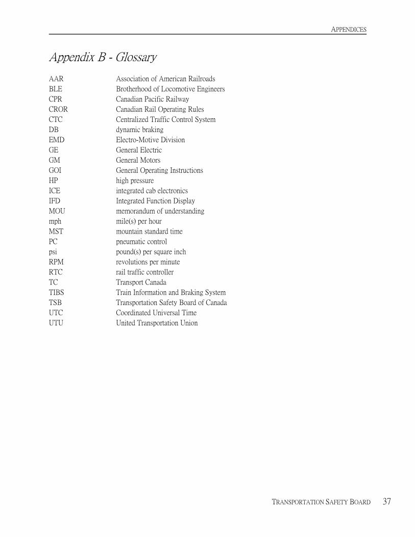
Appendix B - Glossary
AAR Association of American Railroads
BLE Brotherhood of Locomotive Engineers
CPR Canadian Pacific Railway
CROR Canadian Rail Operating Rules
CTC Centralized Traffic Control System
DB dynamic braking
EMD Electro-Motive Division
GE General Electric
GM General Motors
GOI General Operating Instructions
HP high pressure
ICE integrated cab electronics
IFD Integrated Function Display
MOU memorandum of understanding
mph mile(s) per hour
MST mountain standard time
PC pneumatic control
psi pound(s) per square inch
RPM revolutions per minute
RTC rail traffic controller
TC Transport Canada
TIBS Train Information and Braking System
TSB Transportation Safety Board of Canada
UTC Coordinated Universal Time
UTU United Transportation Union