Railroad Flatcar Bridges for Economical Bridge … Flatcar Bridges for Economical Bridge Replacement...
13
Railroad Flatcar Bridges for Economical Bridge Replacement Systems Justin D. Doornink, Terry J. Wipf, and F. Wayne Klaiber Iowa State University 2901 S. Loop Drive, Suite 3100 Ames, IA 50010-8632 [email protected], [email protected], [email protected] ABSTRACT The use of Railroad Flatcars (RRFCs) as the superstructure in low-volume bridges has been investigated in a research project at Iowa State University. These alternative bridges will enable county engineers to replace old, inadequate county bridges for less money and in a shorter construction time than required for a conventional bridge. A feasibility study completed in 1999 by the Bridge Engineering Center at Iowa State University determined that RRFC structures have adequate strength to support Iowa legal traffic loads. In a follow-up research project, two RRFC demonstration bridges with different substructures and types and lengths of RRFCs were designed, constructed, and tested to validate the conclusions of the feasibility study. Bridge behavior predicted by grillage models was supported by data from field load tests, and thus, design recommendations were developed for determining live load distribution in the RRFC bridges. Moreover, it was determined that the engineered RRFC bridges had live load stresses significantly below the steel yield strength and deflections significantly lower than the AASHTO Bridge Design Specification limits. Finally, it was proven that RRFC bridges can be constructed for considerably less money and in a shorter construction time than required for a conventional bridge. Based on the results of this research, it has been determined that through proper RRFC selection, connection, and engineering design, RRFC bridges are a viable, economic alternative for low-volume road bridges. Key words: field testingreplacement structuresRRFC (railroad flatcar) bridges Proceedings of the 2003 Mid-Continent Transportation Research Symposium, Ames, Iowa, August 2003. © 2003 by Iowa State University. The contents of this paper reflect the views of the author(s), who are responsible for the facts and accuracy of the information presented herein.
-
Upload
truongtram -
Category
Documents
-
view
220 -
download
1
Transcript of Railroad Flatcar Bridges for Economical Bridge … Flatcar Bridges for Economical Bridge Replacement...

Railroad Flatcar Bridges for Economical Bridge Replacement Systems
Justin D. Doornink, Terry J. Wipf, and F. Wayne Klaiber Iowa State University 2901 S. Loop Drive, Suite 3100 Ames, IA 50010-8632 [email protected], [email protected], [email protected]
ABSTRACT
The use of Railroad Flatcars (RRFCs) as the superstructure in low-volume bridges has been investigated in a research project at Iowa State University. These alternative bridges will enable county engineers to replace old, inadequate county bridges for less money and in a shorter construction time than required for a conventional bridge.
A feasibility study completed in 1999 by the Bridge Engineering Center at Iowa State University determined that RRFC structures have adequate strength to support Iowa legal traffic loads. In a follow-up research project, two RRFC demonstration bridges with different substructures and types and lengths of RRFCs were designed, constructed, and tested to validate the conclusions of the feasibility study.
Bridge behavior predicted by grillage models was supported by data from field load tests, and thus, design recommendations were developed for determining live load distribution in the RRFC bridges. Moreover, it was determined that the engineered RRFC bridges had live load stresses significantly below the steel yield strength and deflections significantly lower than the AASHTO Bridge Design Specification limits. Finally, it was proven that RRFC bridges can be constructed for considerably less money and in a shorter construction time than required for a conventional bridge. Based on the results of this research, it has been determined that through proper RRFC selection, connection, and engineering design, RRFC bridges are a viable, economic alternative for low-volume road bridges.
Key words: field testingreplacement structuresRRFC (railroad flatcar) bridges
Proceedings of the 2003 Mid-Continent Transportation Research Symposium, Ames, Iowa, August 2003. © 2003 by Iowa State University. The contents of this paper reflect the views of the author(s), who are responsible for the facts and accuracy of the information presented herein.

INTRODUCTION
Approximately eighty-one percent of Iowa’s 25,000 bridges are on secondary roads, and thus, are the responsibility of the counties. The number of bridges in Iowa ranks it 6th in the nation while Iowa’s population ranks 30th. Therefore, the state’s tax base is limited, and as a result, Iowa county engineers have inadequate funds to properly address the secondary road bridge problems. To address this problem, the Bridge Engineering Center at Iowa State University (ISU) investigated the feasibility of using railroad flatcars (RRFCs) as the superstructure on low-volume bridges. Railroad flatcars offer several attractive characteristics that make them desirable for superstructures; they are easy and quick to install, can be used on existing or new abutments, are available in various lengths, require low maintenance, and are relatively inexpensive. In 1999, results from a feasibility study indicated that properly designed RRFC bridges can carry Iowa legal loads (1).
Addressing the recommendations from the 1999 ISU feasibility study, a follow-up research project was initiated in 2000 to design and construct two RRFC demonstration bridges (See Figure 1) (2). Buchanan and Winnebago Counties in Iowa expressed interest in using the RRFC bridge concept since it was envisioned that a RRFC bridge could be constructed for less than one half the cost of a conventional bridge. Therefore, the objectives of the follow-up research were to 1) develop a process for selecting structurally adequate flatcars, 2) develop design and construction guidelines for these alternative LVR bridges, and 3) design, construct, and test two demonstration bridges. The following tasks were undertaken to meet the research objectives:
1. Thorough inspection and selection of readily available, decommissioned RRFCs.
2. Construction and testing of a laboratory connection specimen that simulated a connection between RRFCs.
3. Design and construction of two RRFC demonstration bridges with different types of flatcars, span lengths, and substructures.
4. Field load testing of the RRFC bridges before and after the flatcars were connected.
5. Comparison of analytical and experimental results.
6. Development of a simplified design methodology.
RRFC INSPECTION AND SELECTION
The bridges to be replaced in Buchanan and Winnebago counties were 39 ft (11.9 m) and 56 feet (17.1 m) long (out-to-out), respectively, and thus, it was desired to find RRFCs of similar size. While searching for flatcar suppliers, it was found that most railroad salvage yards own or have access to decommissioned flatcars. Erman Corporation, who supplied the RRFCs for the project, searched for decommissioned RRFCs of the desired lengths and located 56-ft (17.1-m) v-deck RRFCs, 85-ft (25.9-m) RRFCs, and two types of 89-ft (27.1-m) RRFCs. Selection of adequate RRFCs is critical to the success of RRFC bridges, and therefore, five criteria were developed and used to evaluate each type of flatcar.
Doornink, Wipf, and Klaiber 2

(a) Buchanan County Bridge (b) Winnebago County Bridge
FIGURE 1. Photographs of the Completed RRFC Demonstration Bridges
(1) Member Sizes, Support Locations, and Load Transfer Capabilities
To support Iowa legal loads, the RRFC members must be of sufficient size to meet strength and serviceability criteria. The structural elements of each RRFC can be categorized by: decking, girders, secondary members, and transverse members. The decking is the top steel plating on each RRFC; griders and secondary members are oriented longitudinally on the RRFC. Girders are the largest members in the RRFC, and thus, support most of the loads since they are supported at the piers and/or abutments. Each typical RRFC has three girders – two exterior and one interior. The transverse members are connected orthogonally to the longitudinal members, and thus, function to transfer loads from the secondary members to the girders. Secondary members are the remaining longitudinal members that typically transfer load from the decking to the transverse members.
When inspecting RRFCs, it is important to identify regions that are adequate to serve as support locations at the piers and/or abutments. For most RRFCs, the girders will be supported at the piers and/or abutments on the bolsters, or wheel locations on the RRFC. If supported at areas other than the bolster areas, the members need to be checked for adequate strength and stability in the bearing area.
(2) Member Straightness/Damage
While many flatcars have been decommissioned because new designs have made them obsolete or their net worth has depreciated to essentially zero, some flatcars have been removed from service because they have been damaged. Deformed members will not adequately carry or distribute loads, and in addition, they may have been yielded or buckled. Therefore, visual inspection, use of string lines, etc., should be used to determine that all structural members are straight; flatcars with deformed or buckled members, or those with obvious signs of repair, should be rejected.
Doornink, Wipf, and Klaiber 3

(3) Member Connections
RRFC members are either connected by rivets or welds. Rivets, however, can lose significant strength over time primarily due to corrosion. Even if all rivets appear to be in good condition at the time RRFCs are inspected, to avoid future problems, it is recommended that only RRFCs with welded member connections be used. Although fatigue issues should not typically be a concern with bridges on low-volume roads, all welded connections need to be visually inspected to ensure that fatigue cracks are not already present.
(4) Uniform and Matching Cambers
Since several RRFCs must be connected transversely to provide the desired bridge width, careful attention should be given to the camber of each RRFC. Although it was found that cambers are essentially the same for most RRFCs of a particular type, some flatcar cambers do vary from the norm. Not only will significantly differing cambers cause problems when connecting the flatcars, but it could also cause difficulties when trying to construct a smooth driving surface.
(5) RRFC Availability
The use of RRFCs on low-volume bridges is obviously subject to the availability of decommissioned flatcars. Flatcars are removed from service because new designs make them obsolete or because their net worth has depreciated to essentially zero. However, it is recommended that flatcars be selected that have been removed from service because of obsolescence. In addition, if possible, select a type of RRFC that is abundantly available so that bridges may be constructed repetitively, and thus, not requiring new designs.
Using these five criteria and a simplified grillage analysis to evaluate each type of RRFC, it was determined that the 56-ft (17.1-m) v-deck style RRFC and the 89-ft (27.1-m) style RRFC shown in Figure 2 were the best flatcars for the Buchanan County Bridge (BCB) and the Winnebago County Bridge (WCB), respectively.
(b) 89-ft RRFC
15
30 25
24
8’ –
22 75”
2724
9’ – 4.5”
(a) 56-ft RRFC
FIGURE 2. Cross-sections of the RRFCs Used
BRIDGE DESIGN AND CONSTRUCTION
In addition to investigating two different RRFC superstructures, it was possible to design, construct, and investigate different substructures as well as RRFC connections in the demonstration bridges. With the exception of the piling driven for the abutments of each bridge,
Doornink, Wipf, and Klaiber 4

all construction was completed with local maintenance personnel and equipment. Details of each bridge are presented in the following sections.
Buchanan County Bridge
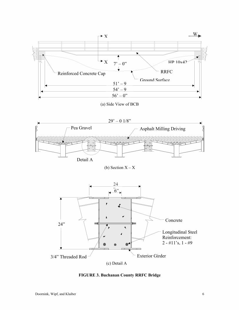
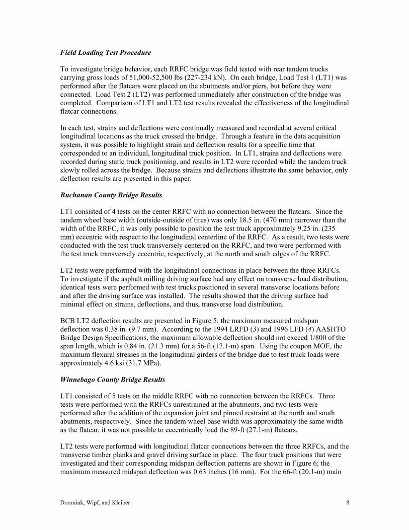
The flatcars for the BCB were supported at their ends, which were checked for strength and stability, on 3-ft (314 mm) square, reinforced concrete cap beams with backwalls; each cap beam was supported by five HP 10x42 steel piling (See Figure 3a). The use of reinforced concrete in the substructure allowed for an integral abutment at one end of the bridge with an expansion joint at the other end. Longitudinal flatcar connections consisting of reinforced concrete beams with transverse threaded rods spaced 24 in. (610 mm) on center were installed between the flatcars for distributing live loads efficiently among the three RRFCs (See Figure 3b and Figure 3c). To ensure that the longitudinal connections supported their own self weight, midspan shoring was used during construction of the connections, which reduced the dead load being distributed to the steel structural members. After structurally connecting the RRFCs, a layer of pea gravel was placed on the RRFCs to facilitate deck drainage. This was followed by installation of an asphalt milling driving surface approximately 5.5 in. (140 mm) and 9.0 in. (229 mm) deep, respectively, at the edges and middle of the bridge (with respect to the tops of the flanges on the exterior members). Finally, a guardrail system was attached.
Winnebago County Bridge
The WCB demonstration bridge is a three span structure because preliminary calculations determined that the 89-ft RRFCs would be inadequate for a single span (See Figure 4a). Therefore, the 89-ft (27.1-m) flatcars were supported by steel-capped piers and abutments at the RRFCs’ bolsters and ends, resulting in a 66-ft (20.1 m) main span with two 10-ft (3.0 m) end spans. The use of steel as the substructure saved construction time by eliminating the need for concrete formwork and curing time. A sheet pile wall provided roadway support at each abutment. For connection between adjacent RRFCs, the top half of the exterior channels above the deck surface was removed on the exterior girders, and longitudinal plates were welded to the top and bottom of the trimmed, exterior channels to form a structural tube (See Figure 4b and Figure 4c). The tube was reinforced with transverse threaded rods on approximately 24 in. (610 mm) centers, and a single #5 longitudinal reinforcement bar was added for crack control prior to filling the void with concrete. After connecting the flatcars, the south ends of the RRFCs were welded to the abutment to restrain vertical and horizontal translation, and expansion joints (which prevented vertical translation) were added to the north ends of the RRFCs, and on each pier. Recycled timber planks were installed transversely and connected to the flatcars to help provide transverse load distribution. A gravel driving surface was placed on top of the timber planks, and a guardrail system was installed.
RRFC BRIDGE PERFORMANCE
Laboratory Tensile Coupon Testing
ASTM tensile tests were performed on steel coupons from both the 56-ft (17.1-m) flatcar and the 89-ft (27.1-m) flatcar. The proportional limit and modulus of elasticity (MOE) from the stress-strain diagrams for both types of flatcars were determined to be approximately 40 ksi (275 MPa) and 29,000 ksi (200,000 MPa), respectively. Thus, a conservative yield strength was assumed to be 36 ksi (248 MPa) for both flatcars.
Doornink, Wipf, and Klaiber 5
(c) Detail A
Longitudinal Steel Reinforcement: 2 - #11’s, 1 - #9
Concrete
3/4” Threaded Rod
624” ”
24”
(b) Section X – X
Detail A
Pea Gravel Asphalt Milling Driving S f
29’ – 0 1/8”
(a) Side View of BCB
56’ – 0”
X
X
Reinforced Concrete Cap RRFC
Ground Surface
HP 10x42 7’ – 0”
51’ – 9 54’ – 9
W
Exterior Girder
FIGURE 3. Buchanan County RRFC Bridge
Doornink, Wipf, and Klaiber 6

Steel Piling
Steel Cap
66’ – 0”
N
(a) Side view of WCB
12’ – 6”
X
X
10’ –10’ –
Sheet Piling
89’ – 0”
RRFC
Ground Surface
1/2” x 6” x 24” Longitudinal Plates(24 in. spaces)
7”
7”
#5 Longitudinal Reinforcement
Trimmed Exterior Channel
3/4” Threaded Rod
ConcreteWeld
Deck
1/2” x 5” x 24” Longitudinal Plates(24 in. spaces)
(c) Detail A
Detail A
26’ – 9 1/2”
Timber Planks
Gravel Driving Surface
(b) Section X – X
FIGURE 4. Winnebago County RRFC Bridge
Doornink, Wipf, and Klaiber 7
Field Loading Test Procedure
To investigate bridge behavior, each RRFC bridge was field tested with rear tandem trucks carrying gross loads of 51,000-52,500 lbs (227-234 kN). On each bridge, Load Test 1 (LT1) was performed after the flatcars were placed on the abutments and/or piers, but before they were connected. Load Test 2 (LT2) was performed immediately after construction of the bridge was completed. Comparison of LT1 and LT2 test results revealed the effectiveness of the longitudinal flatcar connections.
In each test, strains and deflections were continually measured and recorded at several critical longitudinal locations as the truck crossed the bridge. Through a feature in the data acquisition system, it was possible to highlight strain and deflection results for a specific time that corresponded to an individual, longitudinal truck position. In LT1, strains and deflections were recorded during static truck positioning, and results in LT2 were recorded while the tandem truck slowly rolled across the bridge. Because strains and deflections illustrate the same behavior, only deflection results are presented in this paper.
Buchanan County Bridge Results
LT1 consisted of 4 tests on the center RRFC with no connection between the flatcars. Since the tandem wheel base width (outside-outside of tires) was only 18.5 in. (470 mm) narrower than the width of the RRFC, it was only possible to position the test truck approximately 9.25 in. (235 mm) eccentric with respect to the longitudinal centerline of the RRFC. As a result, two tests were conducted with the test truck transversely centered on the RRFC, and two were performed with the test truck transversely eccentric, respectively, at the north and south edges of the RRFC.
LT2 tests were performed with the longitudinal connections in place between the three RRFCs. To investigate if the asphalt milling driving surface had any effect on transverse load distribution, identical tests were performed with test trucks positioned in several transverse locations before and after the driving surface was installed. The results showed that the driving surface had minimal effect on strains, deflections, and thus, transverse load distribution.
BCB LT2 deflection results are presented in Figure 5; the maximum measured midspan deflection was 0.38 in. (9.7 mm). According to the 1994 LRFD (3) and 1996 LFD (4) AASHTO Bridge Design Specifications, the maximum allowable deflection should not exceed 1/800 of the span length, which is 0.84 in. (21.3 mm) for a 56-ft (17.1-m) span. Using the coupon MOE, the maximum flexural stresses in the longitudinal girders of the bridge due to test truck loads were approximately 4.6 ksi (31.7 MPa).
Winnebago County Bridge Results
LT1 consisted of 5 tests on the middle RRFC with no connection between the RRFCs. Three tests were performed with the RRFCs unrestrained at the abutments, and two tests were performed after the addition of the expansion joint and pinned restraint at the north and south abutments, respectively. Since the tandem wheel base width was approximately the same width as the flatcar, it was not possible to eccentrically load the 89-ft (27.1-m) flatcars.
LT2 tests were performed with longitudinal flatcar connections between the three RRFCs, and the transverse timber planks and gravel driving surface in place. The four truck positions that were investigated and their corresponding midspan deflection patterns are shown in Figure 6; the maximum measured midspan deflection was 0.63 inches (16 mm). For the 66-ft (20.1-m) main
Doornink, Wipf, and Klaiber 8

span, according to the 1994 LRFD and 1996 LFD AASHTO Bridge Design Specifications, the maximum allowable deflection should not exceed 0.99 in. (25 mm). Using the coupon MOE, it was determined that the maximum flexural stresses in the longitudinal girders from test truck loads were approximately 7.1 ksi (48.8 MPa).
Doornink, Wipf, and Klaiber 9

Doornink, Wipf, and Klaiber 10
-0.500
-0.400
-0.300
-0.200
-0.100
0.000
0.100
Def
lect
ion
(in.)
Test 1 Test 2 Test 3
Test 4 Test 5 Test 6
Y
Truck A
72” X
72”
Truck A Truck BX Y
1 138.75 -2 253.50 -3 24.00 -4 198.00 -5 24.00 253.006 67.75 209.75
Transverse Position(in.)LT2 Test
Note: Truck B only used in Test 5 and Test 6.
Truck B
N
FIGURE 5. LT2 Midspan Deflections in the BCB

-0.700
-0.600
-0.500
-0.400
-0.300
-0.200
-0.100
0.000
Def
lect
ion
(in.)
Test 1 Test 2 Test 3 Test 4
X 72”
1234
124.75297.50124.75 *
Transverse Truck Position, X(in.)
LT2 Test
24.00
* Speed = 30 mph
E
FIGURE 6. LT2 Midspan Deflections in the WCB
Summary of RRFC Bridge Performance
The deflection patterns for both bridges in LT2 showed that both types of longitudinal connections helped effectively distribute loads transversely across the bridge, and thus, utilized the combined strength of all three flatcars to support the live load. When the maximum live load stresses from the field testing are combined with calculated dead load stresses, the maximum resultant stresses in the longitudinal girders of the BCB and WCB were approximately 12.7 ksi and 16.7 ksi, respectively. Thus, the maximum stresses in the longitudinal members of both
Doornink, Wipf, and Klaiber 11

bridges were well below the conservative yield strength of 36 ksi (248 MPa), and the maximum deflections were significantly less than the AASHTO requirements. Therefore, it has been verified that RRFC bridges can adequately handle Iowa legal loads for tandem trucks.
THEORETICAL ANALYSIS
A grillage model of each bridge was developed using ANSYS, finite element software. When the test truck loads from LT1 and LT2 were applied to each model, the results from the grillage model were in good agreement with the results obtained from the field testing, and thus, showed that stresses and deflections on these types of bridges are predictable. As a result, design recommendations were developed to simplify live load distribution calculations in RRFC bridges.
RRFC BRIDGE CONSTRUCTION COSTS
The economics of the RRFC alternative bridges may be illustrated by comparing RRFC bridge costs with those of a conventional structure. Each 56-ft (17.1-m) RRFC cost $6,500, and each 89-ft (27.1-m) RRFC cost $9,700; both prices included shipping to the bridge site. If the labor and equipment costs are disregarded for each bridge, the BCB and WCB RRFC bridges cost approximately $20 per square foot
and $26 per square foot, respectively. If the actual costs for the county labor and equipment are included, the BCB and WCB RRFC bridge costs would be $39 per square foot and $37 per square foot, respectively. The rationale for excluding the county labor and equipment costs from the RRFC bridge
costs is that they were already budgeted expenses by the county. Thus, those costs would have existed throughout the construction season, regardless of the bridge replacement alternative. Therefore, only the materials and contracted labor associated with the RRFC bridges were extra expenses to the counties. The county alternative to each RRFC bridge was to contract for a concrete slab bridge costing approximately $65 per square foot.
CONCLUSION
Through the design, construction, field testing, and analysis of two RRFC demonstration bridges, it has been determined that RRFC bridges are a viable, economical alternative for low-volume bridges. The success of these demonstration bridges may be directly linked to the careful selection of the RRFC, design of the longitudinal connections between flatcars, and overall design and construction practices.
Therefore, results of this research have introduced a new, efficient, and engineered low-volume bridge replacement that in some situations will help improve secondary road transportation.
Doornink, Wipf, and Klaiber 12
Doornink, Wipf, and Klaiber 13
ACKNOWLEDGEMENTS
The study presented in this paper was conducted by the Bridge Engineering Center at Iowa State University through funding provided by the Iowa Department of Transportation, Highway Division; and the Iowa Highway Research Board. The authors wish to thank Brian Keierleber, Buchanan County Engineer; Jim Witt, Winnebago County Engineer; and personnel for their cooperation and assistance with this project. In addition, a special thanks is extended to Doug Wood, ISU Research Laboratory Manager, and various ISU students for their help with the construction, instrumentation, and field testing of the demonstration bridges.
The opinions, findings, and conclusions expressed in this publication are those of the authors and not necessarily those of the Iowa Department of Transportation.
REFERENCES
1. Wipf, T.J, F.W. Klaiber, and T.L. Threadgold. Use of Railroad Flat Cars for Low-Volume Road Bridges. Iowa DOT Project TR-421. Iowa Department of Transportation. 1999, pp.141.
2. Wipf, T.J, F.W. Klaiber, and J.D. Doornink. Demonstration Project Using Railroad Flatcars for Low-Volume Bridges. Iowa DOT Project TR-444. Iowa Department of Transportation. 2003, pp. 193.
3. AASHTO LRFD Bridge Design Specifications, First Edition, SI Units. American Association of State Highway and Transportation Officials (AASHTO). Washington, D.C. 1994.
4. Standard Specifications for Highway Bridges, Sixteenth Edition. American Association of State Highway and Transportation Officials (AASHTO). Washington, D.C. 1996.


![Reduction of inertial seismic forces in bridges by using ...€¦ · backwall. According to the Eurocode 8 - Part 2 [3], based on technical and economical criteria, checking of expansion](https://static.fdocuments.net/doc/165x107/5e9a74a92d46ce5e6270498d/reduction-of-inertial-seismic-forces-in-bridges-by-using-backwall-according.jpg)