Railcar loading systems - Easyfairs · On Spot loading facilities are filling stations for rail...
20
Railcar loading systems Railcar loading systems transferring liquid hydrocarbons Dipl.-Ing. SCHERZER GmbH LOADING YOUR FUEL www.scherzer.net
Transcript of Railcar loading systems - Easyfairs · On Spot loading facilities are filling stations for rail...

Railcar loading systemsRailcar loading systems transferring liquid hydrocarbons
Dipl.-Ing. SCHERZER GmbH
LOADING YOUR FUEL
www.scherzer.net

Welcome to Dipl.Welcome to Dipl.--Ing. SCHERZER GmbHIng. SCHERZER GmbH The company’s field of activities includes the planning and turn-key construction of plants for handling and storing liquid and gaseous products. Based on more than 45 years of experience in these sectors, the company offers a high degree of professional-ism and is a leader in its field.
Our customers from the petroleum and chemical industries and from a range of other sectors at home and abroad value our groundbreaking technology and our high quality standards as well as our ability to address custom applications while optimizing the economic and environmental aspects of our designs.
Quality Quality -- Safety Safety -- ServiceService Social and environmental policy requirements place high demands on our company on a daily basis, as do constantly changing safety guidelines. These standards are our top priority. Consequently, all areas of the company are subject to a quality management system and certified in accordance with DIN EN ISO 9001:2008.
As a specialized company, we do, of course, have all legal permits necessary to operate both in Germany and abroad.
Our subsidiary, SCHERZER Umwelttechnik GmbH, will handle our after-sales service, allowing us to be there for you long after a successful start-up. Maintenance, the pro-curement of spare parts, and other important services will guarantee the continuous operation of your plant.
Range of services Range of services Our comprehensive range of services includes:
Concept design including essential performance characteristics
Basic engineering
Detail engineering
Delivery of equipment
Assembly of unit (for turnkey contracts)
Supervision (for assembly by customer)
Training
Commissioning
Performance check
Documentation and handover
Services
Scope of supplies and services Our portfolio covers a wide range, allowing us to meet almost every requirement. In addi-tion to new construction, it also comprises the retrofit, conversion or expansion of ex-isting plants for the loading and unloading of:
Railcars
Tank trucks
Ships
for transshipment of:
Light products (petrol/gasoline, diesel, jet fuel, etc.)
Dark products (crude oil, bitumen, etc.)
Chemical products (arenes, acids, etc.)
Stable gas condensate
Liquid gases (propane, butane, LPG, etc.)
Biodiesel / Bioethanol
The scope of our services covers also the new construction and reconstruction of tank farms as well as peripheral components and sys-tems such as:
Vapor recovery units (VRU)
Vapor pendulum systems
Fire-fighting systems
Product and pump systems
Drainage systems
Power-supply systems
Automation technology
Control and monitoring systems
Product data logging
Railroad lines
Company profile:

Railcar loading systemsRailcar loading systems
for liquid hydrocarbons
Dipl.-Ing. SCHERZER GmbH plans and designs storage and handling facilities custom-tailored to the customer´s individual needs in compliance with the applicable national standards and regulations.
The facilities are configured as specified by the customer or based on our extensive years of experience.
Design of loading and rail car positioning systems
Degree of automation (electrical/instrumentation)
PC systems (loading computer, visualization computer, tank management systems)
Data logging systems weighing scale/meter (mass, volume)
Safety equipment (fire fighting, emergency and signalling systems)
Storage capacities (tanks, tank equipment)
Ancillary systems (pumps, recovery systems VRU)
Construction services (for turn-key plants)
Supervision of construction (for non-turnkey plants)
Commissioning of plants
Training of plant operatives
The concept of On Spot rail car loading facilities handling liquid hydrocarbons and mix-tures thereof meets the highest requirements in terms of fire protection and operation-al safety and user-friendliness of the complete automated plant.
Dipl.-Ing. SCHERZER GmbH has specialized in loading systems for rail cars using the On Spot principle for discriminating customers worldwide and for all types of rail cars.
Design pressure: 1.6 MPa PN16 ; 230 psi
Design temperature: + 50°C / - 60°C ; 122 deg F / -76 deg F
High operational safety: operability guarantee with specified design data
Plant performance: guarantee of required daily and annual capacities
Quality assurance: when handling more than one liquid hydrocarbon via multi-product distributor.
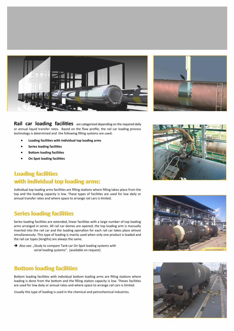
Rail car loading facilities are categorized depending on the required daily
or annual liquid transfer rates. Based on the flow profile, the rail car loading process technology is determined and the following filling systems are used:
Loading facilities with individual top loading arms
Series loading facilities
Bottom loading facilities
On Spot loading facilities
Loading facilities Loading facilities with individual top loading arms: with individual top loading arms: Individual top loading arms facilities are filling stations where filling takes place from the top and the loading capacity is low. These types of facilities are used for low daily or annual transfer rates and where space to arrange rail cars is limited.
Series loading facilities Series loading facilities Series loading facilities are extended, linear facilities with a large number of top loading arms arranged in series. All rail car domes are opened, the top loading arm is manually inserted into the rail car and the loading operation for each rail car takes place almost simultaneously. This type of loading is mainly used when only one product is loaded and the rail car types (lengths) are always the same.
Also see: „Study to compare Tank car On Spot loading systems with serial loading systems”. (available on request)
Bottom loading facilities Bottom loading facilities Bottom loading facilities with individual bottom loading arms are filling stations where loading is done from the bottom and the filling station capacity is low. Theses facilities are used for low daily or annual rates and where space to arrange rail cars is limited.
Usually this type of loading is used in the chemical and petrochemical industries.

What exactly areWhat exactly are
OnOn--Spot loading facilities ?Spot loading facilities ?
On Spot loading facilities are filling stations for rail cars with a top loading system and a high filling capacity. The filling of rail cars is similar to a flow line system (sequential procedure). The filling pipe is arranged inside the On Spot facilities on a hydraulically movable filling pipe slide. The slide can be moved in the X and Y direction, and the fill-ing tube is adjustable in the Z direction.
The rail cars are put in place by a locomotive in front of the On Spot facility.
The first rail car is pulled in by a car pulling device or a remote-controlled shunting vehi-cle and positioned under the filling station.
The filling pipe is moved from the control stand in the operator room located close to the track or between the tracks on a steel structure elevation of approx. 3,700 mm (12 feet) and inserted into the rail car dome. Then, the rail car is loaded.
When loading is complete the car pulling device/shunting vehicle positions the next rail car under the filling station. This goes on until the last rail car of a group of coupled rail cars has been loaded.
Folding stairs are provided in front of and behind the filling station used to open and close the domes.
Flowrate and temperature signals are subject to calibration and are generated through sensors, meters or weighbridges. In addition, these signals are data logged and can be remotely viewed in realtime or accessed in various time intervals. (at the filling station concerned).
On Spot facilities are additionally split into run-through track facilities and dead-end track facilities. This, however, has relevance for the feeding of rail cars only.
For On Spot facilities the track length must be twice the length of a group of coupled rail cars.
Types of On Spot facilities:
On Spot facilities are differentiated by the number of tracks and filling stations.
Facilities range from single-track facilities with one filling station to double-track facili-ties with four or more filling stations.
The design depends on the required daily and annual loading capacities and the square footage available for the coupled rail cars as well as the pump capacity.
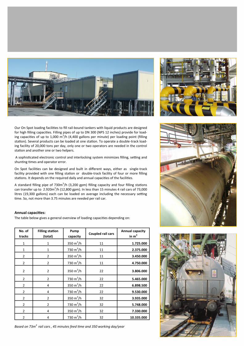
Our On Spot loading facilities to fill rail-bound tankers with liquid products are designed for high filling capacities. Filling pipes of up to DN 300 (NPS 12 inches) provide for load-ing capacities of up to 1,000 m3/h (4,400 gallons per minute) per loading point (filling station). Several products can be loaded at one station. To operate a double-track load-ing facility of 20,000 tons per day, only one or two operators are needed in the control station and another one or two helpers.
A sophisticated electronic control and interlocking system minimizes filling, setting and shunting times and operator error.
On Spot facilities can be designed and built in different ways, either as single-track facility provided with one filling station or double-track facility of four or more filling stations. It depends on the required daily and annual capacities of the facilities.
A standard filling pipe of 730m3/h (3,200 gpm) filling capacity and four filling stations can transfer up to 2.920m3/h (12,800 gpm). In less than 15 minutes 4 rail cars of 73,000 litres (19,300 gallons) each can be loaded on average including the necessary setting time. So, not more than 3.75 minutes are needed per rail car.
Annual capacities:
The table below gives a general overview of loading capacities depending on:
Based on 73m3 rail cars , 45 minutes feed time and 350 working day/year
No. of
tracks
Filling station
(total)
Pump
capacity Coupled rail cars
Annual capacity
in m3
1 1 350 m3/h 11 1.725.000
1 1 730 m3/h 11 2.375.000
2 2 350 m3/h 11 3.450.000
2 2 730 m3/h 11 4.750.000
2 2 350 m3/h 22 3.806.000
2 2 730 m3/h 22 5.465.000
2 4 350 m3/h 22 6.898.500
2 4 730 m3/h 22 9.530.000
2 2 350 m3/h 32 3.935.000
2 2 730 m3/h 32 5.748.000
2 4 350 m3/h 32 7.330.000
2 4 730 m3/h 32 10.335.000

Advantages of the SCHERZER filling tube equipment:
The SCHERZER filling tube is fabricated on very sturdy machine equipment. (The weight of a filling tube amounts to approx. 1700 kg (3,500 lbs). Quite a number of the filling tubes supplied by us have been in service for more than 40 years. The wall thicknesses of the tubes range from 10 – 20 mm (0.4 to 0.8 inches). The guide faces of the tubes are ground and hard chromium plated. The components in contact with the tank car are made of brass or red bronze such as the sealing plate (Russian railcars), the sealing pad of NBR.
Longitudinal and transverse movement if the filling tube for exact position is hydrau-lically remote controlled.
The sealing plate for i.a. Russian railcars is supported on springs between the filling tube and the tank car dome. The cutting edges are protected by sturdy brass strips. The seal-ing plate is vulcanised on a brass plate and screwed to the spring supported carrying plate, thus the sealing can be replaced without difficulty and at low cost.
The sealing bellow for i.a. Non-Russian railcars is fitted on the bellow socket for a com-plete sealing of the railcar dome. A replacement of the sealing bellow (made of 7.5 mm (0.3 inch) thick NBR can be made simply and at low cost.
The compensator allows flexible deflection of the conduit and internal tube. It is not necessary to position the filling tube exactly in the centre on top of the dome opening. The lower filling tube is automatically centred by inflating the sealing bellows. (This version is not possible for Russian tank cars with a sealing plate version)
During the whole loading process, the claws contact the dome tightly. The sealing bel-lows is therefore not subjected to rubbing movement; thus the bellows have a long lifetime cycle.
The gas is returned via a separate high-quality telescopic tube with multiple sealing, with no “low points” to trap condensate. Thus it is ensured that no condensate can accumulate in the system as compared with the hose return systems used formerly.
Sealing of the filling tube after moving out from the tank car is by two (2) O rings and ensures absolute tightness. Residual amounts dripping from the tube walls collect in the tube (max. 10 – 15 l (3 to 5 gallons)).
These residual amounts are automatically drained into the tank car during the next loading process. If this mixture (for product changes only) cannot be accepted in special cases it is possible to drain the residue automatically.
The PCS controlled loading process meets all safety requirements. On request, each filling tube position can be shown visually, and the filling tube lift can be limited depend-ing on the type of tank car used.
High safety in operation is achieved by continuous monitoring of the following sensors: The overfilling safeguard, overpressure safeguard and continuous loading display.
During the last 40 years, more than 210 filling tubes have been mounted and commis-sioned in Austria, Belgium, Bulgaria, Czech Republic, Germany, Great Britain, Hungary, Iran, Lithuania, Poland, Romania, Russia, Slovakia and Switzerland. Due to on-going and continuous improvement and new developments, we are able to offer a sophisticated system meeting state of the art requirements.

Project design and documentationProject design and documentation
The On Spot facilities for liquid hydrocarbons and the related equipment planned and
designed by Dipl.-Ing. SCHERZER GmbH represent state-of-the-art technology and com-
ply with the national statutory provisions for design, e.g. <<UP AUTN 96>> . All require-
ments of national regulations are observed in project planning .
The project documentation is prepared in the following steps:
Basic design (e.g. in Russia as per item 4 SNiP 11-01-95)
Expert report
Permitting for project operation
Project scoping (building permit)
Detailed design (engineering documentation)
Rail construction
Tank construction
Above and below ground structures
Steel construction
Piping
Electrical/instrumentation
Soils report (geological soil investigation)
Surveying (project siting)
Expert report of suppliers’ equipment (by experts)
Operation permit of supplied equipment (e.g. Roztechnadzor)
Final documentation (as-built)
Operation manual
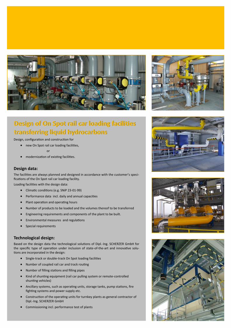
Design of On Spot rail car loading facilities Design of On Spot rail car loading facilities transferring liquid hydrocarbons transferring liquid hydrocarbons Design, configuration and construction for
new On Spot rail car loading facilities,
or
modernization of existing facilities.
Design data: The facilities are always planned and designed in accordance with the customer’s speci-fications of the On Spot rail car loading facility.
Loading facilities with the design data:
Climatic conditions (e.g. SNiP 23-01-99)
Performance data incl. daily and annual capacities
Plant operation and operating hours
Number of products to be loaded and the volumes thereof to be transferred
Engineering requirements and components of the plant to be built.
Environmental measures and regulations
Special requirements
Technological design: Based on the design data the technological solutions of Dipl.-Ing. SCHERZER GmbH for the specific type of operation under inclusion of state-of-the-art and innovative solu-tions are incorporated in the design:
Single-track or double-track On Spot loading facilities
Number of coupled rail car and track routing
Number of filling stations and filling pipes
Kind of shunting equipment (rail car pulling system or remote-controlled shunting vehicles)
Ancillary systems, such as operating units, storage tanks, pump stations, fire fighting systems and power supply etc.
Construction of the operating units for turnkey plants as general contractor of Dipl.-Ing. SCHERZER GmbH
Commissioning incl. performance test of plants

Rail car loading facilities are designed and configured in accordance with the customer’s specifications.
Design example (2 rails / 4 filling stations) :
Double-track facility up to: 2 x 32 rail cars
Loading capacity approx. 400 rail cars/d
Workforce 4
Daily capacity max.: 29,368 m³/d (7,750,000 gallons per day) 22,026 mt/d
Annual capacity (350 days): 7,709,100 T
Description of technological operating systems
The double-track loading facility is designed for max. 32 rail cars/track. The rail cars are positioned automatically under the filling station by a car pulling device or shunting vehicle.
For access the rail cars have mobile folding stairs arranged in front of and behind the filling station to open and close the rail car dome.
Filling systems
Major components of the filling systems for each filling station are:
Hydraulic filling pipe incl. telescopic gas pipe
Articulated arms for product and displaced vapors
Product distributor with quality assurance system
Monitoring system for filling pipe positioning
Controlled product double valves DN 250 for each product
Controlled gas valves and detonation arrestors DN100/150
Folding stairs, 5-step, with monitored parking position
Horizontally movable for safe rail car access
Pneumatic actuation
Provided with protecting cage
Earth tester for monitored forced earthing of the filling pipe and the rail car during the loading operation (Eastern Europe).
Filling control
To avoid electrostatic charging while filling of the rail car takes place, the initial volumetric flow is limited to approx. 300 m³/h (1,320 gpm) per filling station.
To measure the volumetric flow, either a cali-brated volume/mass flow meter or a weigh-bridge is used.
The output signal of the data logging system is processed by the SPC and used to control the electro-pneumatic control valve.
The filling control is used to:
Pre-set loading quantities/rail car
keep the flow rate
switch off automatically as soon as the pre-set quantities have been reached, in a controlled manner and free of pressure surges. (no dynamic pressure surges).

Process control and instrumentation systems Control and visualisation of the whole process by process control and instrumentation systems (e.g. WinCC of Siemens) and PCS control systems.
Server/client based process control system with centralized data storage based on Win-dows computer systems
Creation of redundant systems:
Process connection of PCS control systems (e.g. Simatik S7 of Siemens) via bus systems (Industrial Ethernet or Profibus)
Integration of tank storage management systems, quantity recording systems admitted by the calibration authorities, and ID card reading systems into the whole concept
Connection of tank measuring equipment (e.g. radar filling level measuring systems) with OPC (OLE for Process Control)
Connection of process signals in PCS control systems via standardised field bus systems (Profibus-DP, Profibus-PA)
Coupling to external systems and their integration into the process automation systems as far as possible via standardized or user specific protocols (e.g. Profibus, Modbus, 3964R, RK512 or other)
SAP connections of loading computer systems and customer specific adaptations are possible.
Process visualisation
Complex On Spot railcar loading facilities including all sub-systems such as VRU systems, fire fighting systems, power supply systems, shunting units, product tanks, product pumps, piping systems, etc. are provided with subordinate machine-near operation and monitoring systems based on Windows computer systems.
Visualisation and process operation in visualisation pictures specifically prepared for this process.
Specification and check of process parameters
Visualisation, recording and archiving of alarms
Incorporation of subordinate process visualisation systems
into the process control system
Data logging
The data logging subject to calibration for the
loading quantity/rail car is effected by the:
Weighbridge under the filling station, or
Coriolis mass flow meters and volumeter
provided with turbine and slide vane sys-
tems respectively.
The decision which type of data logger is to be
used is taken in the basic design and depends
on a number of project requirements.
As a rule a Corolis mass flow meter or volu-
meter is useful for small product quantities.
But if future extensions are planned, a weigh-
bridge should be provided from the start. In
such case the car pit can be planned as col-
lecting pit to meet the requirements of the
waste water management regulations.
The weighbridges can be individual or inter-
connected weighbridges depending on the
plant concept and the various rail car types.
Up to three weighbridges are typical in the
overall concept.
ControlControl–– and automation systemsand automation systems
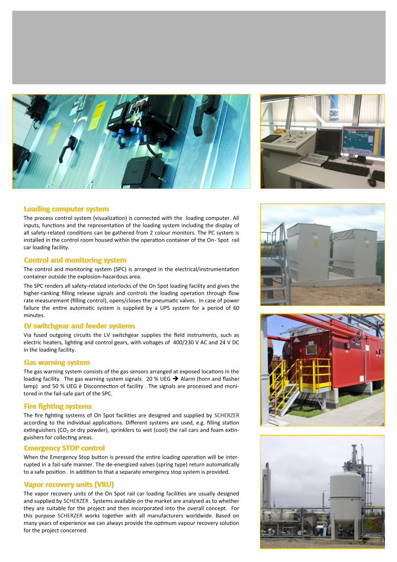
Loading computer systemLoading computer system The process control system (visualization) is connected with the loading computer. All inputs, functions and the representation of the loading system including the display of all safety-related conditions can be gathered from 2 colour monitors. The PC system is installed in the control room housed within the operation container of the On- Spot rail car loading facility.
Control and monitoring system Control and monitoring system The control and monitoring system (SPC) is arranged in the electrical/instrumentation container outside the explosion-hazardous area.
The SPC renders all safety-related interlocks of the On Spot loading facility and gives the higher-ranking filling release signals and controls the loading operation through flow rate measurement (filling control), opens/closes the pneumatic valves. In case of power failure the entire automatic system is supplied by a UPS system for a period of 60 minutes.
LV switchgear and feeder systems LV switchgear and feeder systems Via fused outgoing circuits the LV switchgear supplies the field instruments, such as electric heaters, lighting and control gears, with voltages of 400/230 V AC and 24 V DC in the loading facility.
Gas warning systemGas warning system The gas warning system consists of the gas sensors arranged at exposed locations in the loading facility. The gas warning system signals: 20 % UEG Alarm (horn and flasher lamp) and 50 % UEG è Disconnection of facility . The signals are processed and moni-tored in the fail-safe part of the SPC.
Fire fighting systemsFire fighting systems The fire fighting systems of On Spot facilities are designed and supplied by SCHERZER according to the individual applications. Different systems are used, e.g. filling station extinguishers (CO2 or dry powder), sprinklers to wet (cool) the rail cars and foam extin-guishers for collecting areas.
Emergency STOP controlEmergency STOP control When the Emergency Stop button is pressed the entire loading operation will be inter-rupted in a fail-safe manner. The de-energized valves (spring type) return automatically to a safe position. In addition to that a separate emergency stop system is provided.
Vapor recovery units (VRU)Vapor recovery units (VRU) The vapor recovery units of the On Spot rail car loading facilities are usually designed and supplied by SCHERZER . Systems available on the market are analysed as to whether they are suitable for the project and then incorporated into the overall concept. For this purpose SCHERZER works together with all manufacturers worldwide. Based on many years of experience we can always provide the optimum vapour recovery solution for the project concerned.
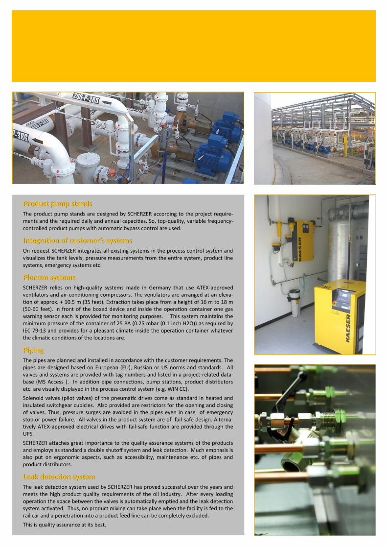
Product pump standsProduct pump stands The product pump stands are designed by SCHERZER according to the project require-ments and the required daily and annual capacities. So, top-quality, variable frequency-controlled product pumps with automatic bypass control are used.
Integration of customer’s systems Integration of customer’s systems On request SCHERZER integrates all existing systems in the process control system and visualizes the tank levels, pressure measurements from the entire system, product line systems, emergency systems etc.
Plenum systemsPlenum systems SCHERZER relies on high-quality systems made in Germany that use ATEX-approved ventilators and air-conditioning compressors. The ventilators are arranged at an eleva-tion of approx. + 10.5 m (35 feet). Extraction takes place from a height of 16 m to 18 m (50-60 feet). In front of the boxed device and inside the operation container one gas warning sensor each is provided for monitoring purposes. This system maintains the minimum pressure of the container of 25 PA (0.25 mbar (0.1 inch H2O)) as required by IEC 79-13 and provides for a pleasant climate inside the operation container whatever the climatic conditions of the locations are.
PipingPiping The pipes are planned and installed in accordance with the customer requirements. The pipes are designed based on European (EU), Russian or US norms and standards. All valves and systems are provided with tag numbers and listed in a project-related data-base (MS Access ). In addition pipe connections, pump stations, product distributors etc. are visually displayed in the process control system (e.g. WIN CC).
Solenoid valves (pilot valves) of the pneumatic drives come as standard in heated and insulated switchgear cubicles. Also provided are restrictors for the opening and closing of valves. Thus, pressure surges are avoided in the pipes even in case of emergency stop or power failure. All valves in the product system are of fail-safe design. Alterna-tively ATEX-approved electrical drives with fail-safe function are provided through the UPS.
SCHERZER attaches great importance to the quality assurance systems of the products and employs as standard a double shutoff system and leak detection. Much emphasis is also put on ergonomic aspects, such as accessibility, maintenance etc. of pipes and product distributors.
Leak detection systemLeak detection system The leak detection system used by SCHERZER has proved successful over the years and meets the high product quality requirements of the oil industry. After every loading operation the space between the valves is automatically emptied and the leak detection system activated. Thus, no product mixing can take place when the facility is fed to the rail car and a penetration into a product feed line can be completely excluded.
This is quality assurance at its best.

Rail car pulling devices and Rail car pulling devices and
remoteremote--controlled shunting vehicles controlled shunting vehicles
SCHERZER uses high-quality shunting equipment made in Germany. The shunting sys-
tems available on the market have been developed to fit the rough conditions of an On
Spot facility. SCHERZER does the programming itself and relies on an automatic posi-
tioning of rail cars under the filling station and on the weighbridge respectively and a
machine oriented visualization.
A whole range of shunting systems is used. Depending on the application, buffer cars
with or without siding or pusher cars directly acting onto wagon wheels are used, which
rail cars can run on.
Buffer cars are used when the number of coupled rail cars is large. Special sidings are
provided for through tracks.
Pusher cars directly acting onto wagon wheels are used for up to 11 coupled rail cars
and have the big advantage that they can be ‚run over’ by the rail cars. An auxiliary track
is no longer required with the new facility because this car can run on the main track.
Remote-controlled shunting vehicles
Compared to conventional cable systems remote-controlled shunting vehicles are par-
ticularly useful, especially when it comes to installation and maintenance (no founda-
tions and cables).
Diesel-driven shunting vehicles are also very flexible, e.g. may be used on several load-
ing tracks and to feed and remove coupled rail cars.
Centrifugal fansCentrifugal fans On Spot facilities for loading Russian rail car types use special ATEX-approved centrifugal
fans. They provide special protection against emergent hydrocarbon vapors from the
dome while filling takes place. Standard control is by a vacuum system.

The containers designed by SCHERZER are fully equipped when supplied. All switch-gear cubicles, operator panels, control points, ventilation systems, heating system etc. are completely installed and wired on a terminal strip. Prior to delivery they undergo a detailed performance test including all sub-systems to the extent possible at the factory. The end user is invited to witness such test. All equipment including desks, chairs, thermometers, shelves, writing utensils, light fittings etc. are supplied.
Electrical/Instrumentation container The standard type of this container is a combined unit split into:
Compressor room (optional),
equipped with a ready-to-use redundant compressor for instrument air, dew point –60°C (-76 deg F).
Electrical/instrumentation room,
equipped with a ready-to-use control and monitoring system, LV switchgear and UPS for voltage supply of the automatic system in case of power failure.
The electrical/instrumentation room is also provided with heating, lighting and air-conditioning system.
In Russia, for example, the electrical room is provided with an automatic CO2 extin-guishing system. A temporary workplace for the maintenance and service personnel is also provided.
CO2 extinguishing system The CO2 extinguishers are arranged in the area of the On Spot rail car loading facility. The CO2 container is supplied completely equipped and ready for use. In case of fire the extinguishers are triggered automatically by the fire alarm system (UV/IR alarm system) or manually by the push button call point on the operator panels.
After installation at the factory the systems and system components undergo a thor-ough functional test. During this test all communications are put into operation and to the extent possible, components are tested, too. Usually the end user witnesses such test for the purpose of pre-acceptance.
Operation container inside the
On Spot facility
This container is designed in accordance with
the plant concept.
For facilities with 2 filling stations the con-
tainer will be approx. 9 m (30 feet) long, and
for 4 filling stations the container will be
approx. 16 m (50 feet) long. The side win-
dows are made of laminated glass and are
inclined at an optimal angle to the filling sta-
tion.
The installation and cabling of vents, opera-
tor panels, network cabinets including net-
work connection distributors and all neces-
sary accessories takes place at the factory
prior to shipping the unit to the site.
Also provided are all necessary computer
systems for a safe operation of the facility.
The operation container is the central control
station of the On Spot facility and is perma-
nently manned as long as the facility runs.
Here, all systems are monitored and the load-
ing data checked.
In accordance with IEC 79-13 this container is
designed for an internal pressure of over 200
Pa (0.8 inch H2O). Local requirements (e.g.
UP-AUTN-96 ) will be met.
After installation at the factory the systems
and system components undergo a thorough
functional test. During this test all communi-
cations are put into operation and to the
extent possible, components are tested, too.
Usually the end user witnesses such test for
the purpose of pre-acceptance.
Electrical/instrumentation, operation and
CO2 extinguisher containers

Supervision,
Training,
Commissioning Training, supervision and commissioning is performed by highly qualified specialists of
Dipl.-Ing. SCHERZER GmbH.
In-house training is generally combined with the function – test of the facility. Therefore
it is secured that training activities are performed directly at control systems of the facil-
ity. During training, substantial functions are explained as well as the complete engi-
neering system such as tag number system, circuit diagram etc.
Our specialists of supervision are sub – classified regarding Mechanic, earth work and
foundations, electric and MSR. Further a Chief supervisor for coordination and as the
contact person for the customer is foreseen. Detailed schedules and organization sheets
and plans for supervision and commissioning are worked out.
After Sales Service
Our After Sales Service are performed by the specialists of our subsidiary company
SCHERZER Umwelttechnik GmbH.
Maintenance contracts can be settled directly and will be split between mechanical
section and EMSR. Short term fault analyses are carried out by a remote diagnosis with
VPN or modem connection for a quick solution of problems. These checks can be made
from the headquarter in Germany or from regional offices located in more close proxim-
ity to the end-user location
.
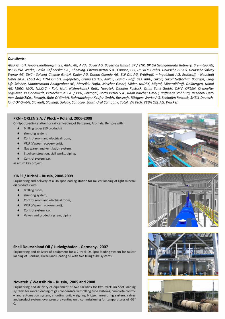
PKN - ORLEN S.A. / Plock – Poland, 2006-2008 On-Spot Loading station for rail car loading of Benzenes, Aromats, Benzole with :
6 filling tubes (10 products),
shunting system,
Control room and electrical room,
VRU (Vapour recovery unit),
Gas warn- and ventilation system,
Steel construction, civil works, piping,
Control system a.o.
as a turn key project.
KINEF / Kirishi – Russia, 2008-2009 Engineering and delivery of a On-spot loading station for rail car loading of light mineral oil products with:
8 filling tubes,
shunting system,
Control room and electrical room,
VRU (Vapour recovery unit),
Control system a.o.
Valves and product system, piping
Shell Deutschland Oil / Ludwigshafen - Germany, 2007 Engineering and delivery of equipment for a 2 track On-Spot loading system for railcar loading of Benzine, Diesel and Heating oil with two filling tube systems.
Novatek / Westsibiria – Russia, 2005 and 2008 Engineering and delivery of equipment of two facilities for two track On-Spot loading systems for railcar loading of gas condensate with filling tube systems, complete control – and automation system, shunting unit, weighing bridge, measuring system, valves and product system, over pressure venting unit, commissioning for temperatures of -55°C.
Our clients:
AGIP GmbH, Angarsknefteorgsintez, ARAL AG, AVIA, Bayer AG, Bayernoil GmbH, BP / TNK, BP Oil Grangemouth Refinery, Brenntag AG, BSL BUNA Werke, Ceska Rafinerska S.A., Cheming, Chemo-petrol S.A., Conoco, CPI, DEFROL GmbH, Deutsche BP AG, Deutsche Solvay Werke AG, DHC - Solvent Chemie GmbH, Didier AG, Donau Chemie AG, ELF OIL AG, Erdölraff. – Ingolstadt AG, Erdölraff. - Neustadt GmbH&Co., ESSO AG, FINA GmbH, Jugopetrol, Grupa LOTOS, KINEF, Leuna - Raff. ges. mbH, Lukoil, Lukoil Neftochim Bourgas, Lurgi Life Scienсe, Mannesmann Anlagenbau AG, Mazeikiu Nafta, Melcher GmbH, Mider, MIDEX, Migrol, Mineralölraff. Dollbergen, Minol AG, MIRO, MOL, N.I.O.C. - Kala Naft, Nizhnekamsk Raff., Novatek, Ölhafen Rostock, Omni Tank GmbH, ÖMV, ORLEN, Orsknefte-orgsintez, PCK-Schwedt, Petrochemia S.A. / PKN, Petrogal, Porta Petrol S.A., Raab Karcher GmbH, Raffinerie Vohburg, Reederei Dett-mer GmbH&Co., Rosneft, Ruhr Öl GmbH, Ruhrtanklager Kaufer GmbH, Russneft, Rüttgers Werke AG, Seehafen Rostock, SHELL Deutsch-land Oil GmbH, Slavneft, Slovnaft, Solvay, Sonacop, South Ural Company, Total, VA Tech, VEBA OEL AG, Wacker.
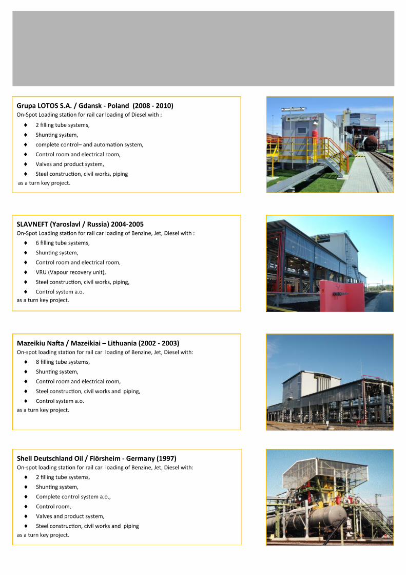
Grupa LOTOS S.A. / Gdansk - Poland (2008 - 2010) On-Spot Loading station for rail car loading of Diesel with :
2 filling tube systems,
Shunting system,
complete control– and automation system,
Control room and electrical room,
Valves and product system,
Steel construction, civil works, piping
as a turn key project.
SLAVNEFT (Yaroslavl / Russia) 2004-2005 On-Spot Loading station for rail car loading of Benzine, Jet, Diesel with :
6 filling tube systems,
Shunting system,
Control room and electrical room,
VRU (Vapour recovery unit),
Steel construction, civil works, piping,
Control system a.o.
as a turn key project.
Mazeikiu Nafta / Mazeikiai – Lithuania (2002 - 2003) On-spot loading station for rail car loading of Benzine, Jet, Diesel with:
8 filling tube systems,
Shunting system,
Control room and electrical room,
Steel construction, civil works and piping,
Control system a.o.
as a turn key project.
Shell Deutschland Oil / Flörsheim - Germany (1997) On-spot loading station for rail car loading of Benzine, Jet, Diesel with:
2 filling tube systems,
Shunting system,
Complete control system a.o.,
Control room,
Valves and product system,
Steel construction, civil works and piping
as a turn key project.
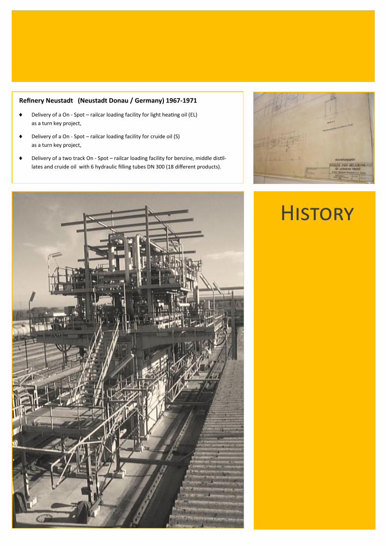
Refinery Neustadt (Neustadt Donau / Germany) 1967-1971
Delivery of a On - Spot – railcar loading facility for light heating oil (EL)
as a turn key project,
Delivery of a On - Spot – railcar loading facility for cruide oil (S)
as a turn key project,
Delivery of a two track On - Spot – railcar loading facility for benzine, middle distil-
lates and cruide oil with 6 hydraulic filling tubes DN 300 (18 different products).
History

Main office Adlerstr. 16a
45307 Essen - Germany
Telefon: +49 / 201 / 855 14 - 0
Fax: +49 / 201 / 55 14 04
E-Mail: [email protected]
www.Scherzer.net
Office Rostock Dierkower Damm 38d
18146 Rostock - Germany
Telefon: +49 / 381 / 453 69 47
Fax: +49 / 381 / 453 69 45
E-Mail: [email protected]
www.Scherzer.net
Office Moscow ILM / Dr. Peter Igenbergs
Podkopaevskij Per D. 9, Bau 2
109028 Moscow / Russia
Telefon: +7 / 495 / 624 02 28
Fax: +7 / 495 / 624 50 87
E-Mail: [email protected]
Further representatives in:
Balkan Republics
Belgium
Benin
Czech Republic
France
Hungary
India
Iran
Italy
Poland
Portugal
Russian Federation and C.I.S.
Slovakia
Turkey
USA / Canada
Stand: 08/2013
Other brochures of Dipl.-Ing. SCHERZER GmbH
Company profile
Railcar loading systems
Railcar unloading systems
Railcar filling tube systems
Study to compare tank car on spot loading systems with
serial loading systems
LPG loading and unloading systems
Tank truck loading and unloading systems
Ship loading and unloading systems
Tankfarms, handling plants and
Vapor Recovery Units (VRU)
Detailed reference list
We are pleased to send you a brochure on request.
Dipl.-Ing. SCHERZER GmbH
LOADING YOUR FUEL