Radiometry - University of California, San Diego · distance r from a small emitting area dA 1? ......
7
1 CSE 252A Radiometry Radiometry Computer Vision I CSE252A Lecture 5-Part II CSE 252A Radiometry Radiometry • Read Chapter 4 of Ponce & Forsyth • Solid Angle • Irradiance • Radiance • BRDF • Lambertian/Phong BRDF CSE 252A Measuring Angle Measuring Angle • The solid angle subtended by an object from a point P is the area of the projection of the object onto the unit sphere centered at P. • Measured in steradians, sr • Definition is analogous to projected angle in 2D • If I’m at P, and I look out, solid angle tells me how much of my view is filled with an object CSE 252A Solid Angle Solid Angle • By analogy with angle (in radians), the solid angle subtended by a region at a point is the area projected on a unit sphere centered at that point • The solid angle subtended by a patch area dA is given by dw = dA cosJ r 2 CSE 252A Radiance Radiance • Power is energy per unit time • Radiance: Power traveling at some point in a specified direction, per unit area perpendicular to the direction of travel, per unit solid angle • Symbol: L(x,θ,φ • Units: watts per square meter per steradian : w/(m 2 sr 1 ) x dA q dw w q d dA P L ) cos ( = CSE 252A Radiance transfer Radiance transfer What is the power received by a small area dA 2 at distance r from a small emitting area dA 1 ? From definition of radiance w q d dA P L ) cos ( = From definition of solid angle 2 cos r dA d q w = 2 1 2 1 2 2 1 1 1 cos cos cos q q w q dA dA r L d LdA P = = > -
Transcript of Radiometry - University of California, San Diego · distance r from a small emitting area dA 1? ......

1
CSE 252A
RadiometryRadiometry
Computer Vision ICSE252A
Lecture 5-Part II
CSE 252A
RadiometryRadiometry
• Read Chapter 4 of Ponce & Forsyth
• Solid Angle• Irradiance• Radiance• BRDF• Lambertian/Phong BRDF
CSE 252A
Measuring AngleMeasuring Angle
• The solid angle subtended by an object from a point P is the area of the projection of the object onto the unit sphere centered at P.
• Measured in steradians, sr• Definition is analogous to projected angle in 2D• If I’m at P, and I look out, solid angle tells me how
much of my view is filled with an object CSE 252A
Solid AngleSolid Angle
• By analogy with angle (in radians), the solid angle subtended by a region at a point is the area projected on a unit sphere centered at that point
• The solid angle subtended by a patch area dA is given by
dω =dAcosϑ
r2
CSE 252A
Radiance Radiance • Power is energy per unit time
• Radiance: Power traveling at some point in a specified direction, per unit area perpendicular to the direction of travel, per unit solid angle
• Symbol: L(x,θ,φ)
• Units: watts per square meter per steradian : w/(m2sr1)
x
dA
θ
dω
ωθ ddAP
L)cos(
=
CSE 252A
Radiance transfer Radiance transfer What is the power received by a small area dA2 at distance r from a small emitting area dA1?
From definition of radiance
ωθ ddAP
L)cos(
=
From definition of solid angle
2
cosr
dAd
θω =
21212
2111
coscos
cos
θθ
ωθ
dAdArL
dLdAP
=
= >−
2
CSE 252A
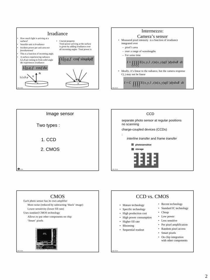
IrradianceIrradiance• How much light is arriving at a
surface?• Sensible unit is Irradiance• Incident power per unit area not
foreshortened• This is a function of incoming angle. • A surface experiencing radiance
L(x,θ,φ) coming in from solid angle dω experiences irradiance:
• Crucial property: Total power arriving at the surface is given by adding irradiance over all incoming angles Total power is
( ) ωφφθ dxL cos,,
( )∫Ω
φθθφφθ ddxL sincos,,
NφL(x,θ,φ)
x x
CSE 252A
Intermezzo:Intermezzo:Camera’s sensorCamera’s sensor
• Measured pixel intensity is a function of irradiance integrated over – pixel’s area– over a range of wavelengths– For some time
• Ideally, it’s linear to the radiance, but the camera response C(.) may not be linear
∫ ∫ ∫ ∫ =t x y
dtdydxdqyxstyxEIλ
λλλ )(),(),,,(
= ∫ ∫ ∫ ∫
t x y
dtdydxdqyxstyxECIλ
λλλ )(),(),,,(
CSE 252A
Image sensor
Two types :
è
1. CCD
2. CMOS
CSE 252A
CCD
separate photo sensor at regular positionsno scanning
charge-coupled devices (CCDs)
: interline transfer and frame transfer
photosensitive
storage
CSE 252A
CMOSCMOSEach photo sensor has its own amplifier
More noise (reduced by subtracting ‘black’ image)Lower sensitivity (lower fill rate)
Uses standard CMOS technologyAllows to put other components on chip‘Smart’ pixels
CSE 252A
CCD vs. CMOSCCD vs. CMOS
• Mature technology• Specific technology• High production cost• High power consumption• Higher fill rate• Blooming• Sequential readout
• Recent technology• Standard IC technology• Cheap• Low power• Less sensitive• Per pixel amplification• Random pixel access• Smart pixels• On chip integration
with other components

3
CSE 252A
Color CamerasColor Cameras
We consider 3 concepts:
1. Prism (with 3 sensors)2. Filter mosaic3. Filter wheel
… and X3
CSE 252A
Prism Prism colourcolour cameracameraSeparate light in 3 beams using dichroic prismRequires 3 sensors & precise alignmentGood color separation
CSE 252A
Filter mosaic Filter mosaic Coat filter directly on sensor
Demosaicing (obtain full colour & full resolution image)
CSE 252A
Filter wheelFilter wheelRotate multiple filters in front of lensAllows more than 3 colour bands
Only suitable for static scenes
CSE 252A
Prism vs. mosaic vs. wheelPrism vs. mosaic vs. wheelWheel
1GoodAverageLowMotion3 or more
approach# sensorsSeparationCostFramerateArtefactsBands
Prism3
HighHighHighLow
3
High-endcameras
Mosaic1
AverageLowHighAliasing
3
Low-endcameras
Scientific applications
CSE 252A
new color CMOS sensornew color CMOS sensorFoveon’sFoveon’s X3X3
better image qualitysmarter pixels

4
CSE 252A
Example: Radiometry of thin lensesExample: Radiometry of thin lenses
( ) ( )22 cos/cos
cos/'cos'
ββδ
ααδδω
zA
zA ==
2
'coscos
'
=
zz
AA
βα
δδ
( )3
2
2
2
cos4cos/
cos4
απ
ααπ
==Ω
zd
zd
βαδπ
βδδ coscos4
cos 32
ALzd
ALP
=Ω=
βαδδπ
δδ
coscos'4'
32
AA
Lzd
AP
E
==
Lzd
E
= α
π 42
cos4
E: Image irradianceL: emitted radianced : Lens diamterZ: depthα: Angle of patch from optical axis CSE 252A
Light at surfacesLight at surfaces
Many effects when light strikes a surface -- could be:
• transmitted– Skin, glass
• reflected– mirror
• scattered– milk
• travel along the surface and leave at some other point
• absorbed– sweaty skin
Assume that• surfaces don’t fluoresce
– e.g. scorpions, detergents • surfaces don’t emit light (i.e.
are cool)• all the light leaving a point is
due to that arriving at that point
CSE 252A
BRDFBRDFWith assumptions in previous slide• Bi-directional Reflectance Distribution
Function ρ(θin, φin ; θout, φout)
•• Ratio of incident irradiance to Ratio of incident irradiance to emitted radianceemitted radiance
• Function of– Incoming light direction:
θin , φin– Outgoing light direction:
θout , φout
n(θin,φin)
(θout,φout)
( ) ( )( ) ωφφθ
φθφθφθρ
dxLxL
xininini
outoutooutoutinin cos,;
,;,;,; =
CSE 252A
CSE 252A
Surface Reflectance ModelsSurface Reflectance Models
• Lambertian• Phong• Physics-based
– Specular [Blinn 1977], [Cook-Torrance 1982], [Ward 1992]
– Diffuse [Hanrahan, Kreuger 1993]
– Generalized Lambertian [Oren, Nayar 1995]
– Thoroughly Pitted Surfaces [Koenderink et al 1999]
• Phenomenological[Koenderink, Van Doorn 1996]
Common Models Arbitrary Reflectance
• Non-parametric model• Anisotropic• Non-uniform over surface• BRDF Measurement [Dana et
al, 1999], [Marschner ]
CSE 252A
Lambertian (Diffuse) SurfaceLambertian (Diffuse) Surface
• BRDF is a constant called the albedo
• Emitted radiance is NOT a function of outgoing direction – i.e. constant in all directions.
• For lighting coming in single direction, emitted radiance is proportional to cosine of the angle between normal and light direction
Lr = N . ωι

5
CSE 252A
Lambertian reflectionLambertian reflection
• Lambertian• Matte• Diffuse
Light is radiated equally in all directions
CSE 252A
Specular Reflection: Smooth SurfaceSpecular Reflection: Smooth Surface
N
CSE 252A
Rough Specular SurfaceRough Specular Surface
Phong Lobe
CSE 252A
CSE 252A
GonioreflectometersGonioreflectometers
• Three degrees of freedom spread among light source, detector, and/or sample
CSE 252A
GonioreflectometersGonioreflectometers
• Three degrees of freedom spread among light source, detector, and/or sample
6
CSE 252A
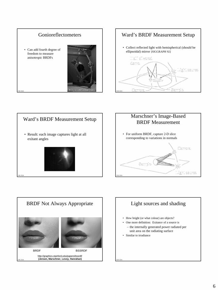
GonioreflectometersGonioreflectometers
• Can add fourth degree of freedom to measure anisotropic BRDFs
CSE 252A
Ward’s BRDF Measurement SetupWard’s BRDF Measurement Setup
• Collect reflected light with hemispherical (should be ellipsoidal) mirror [SIGGRAPH 92]
CSE 252A
Ward’s BRDF Measurement SetupWard’s BRDF Measurement Setup
• Result: each image captures light at all exitant angles
CSE 252A
Marschner’sMarschner’s ImageImage--BasedBasedBRDF MeasurementBRDF Measurement
• For uniform BRDF, capture 2-D slice corresponding to variations in normals
CSE 252A
BRDF Not Always AppropriateBRDF Not Always Appropriate
http://graphics.stanford.edu/papers/bssrdf/(Jensen, Marschner, Levoy, Hanrahan)
BRDF BSSRDF
CSE 252A
Light sources and shadingLight sources and shading
• How bright (or what colour) are objects?• One more definition: Exitance of a source is
– the internally generated power radiated per unit area on the radiating surface
• Similar to irradiance
7
CSE 252A
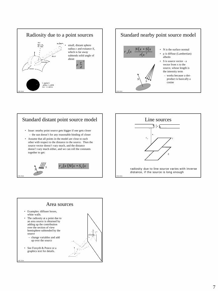
RadiosityRadiosity due to a point sourcesdue to a point sources
• small, distant sphere radius ε and exitance E, which is far away subtends solid angle of about
πεd
2
CSE 252A
Standard nearby point source modelStandard nearby point source model
• N is the surface normal• ρ is diffuse (Lambertian)
albedo• S is source vector - a
vector from x to the source, whose length is the intensity term– works because a dot-
product is basically a cosine
( ) ( ) ( )( )
•2xr
xSxNxdρ
NS
CSE 252A
Standard distant point source modelStandard distant point source model
• Issue: nearby point source gets bigger if one gets closer– the sun doesn’t for any reasonable binding of closer
• Assume that all points in the model are close to each other with respect to the distance to the source. Then the source vector doesn’t vary much, and the distance doesn’t vary much either, and we can roll the constants together to get:
( ) ( ) ( )( )xSxNx dd •ρN
S
CSE 252A
Line sources Line sources
radiosity due to line source varies with inverse distance, if the source is long enough
CSE 252A
Area sourcesArea sources• Examples: diffuser boxes,
white walls.• The radiosity at a point due to
an area source is obtained by adding up the contribution over the section of view hemisphere subtended by the source – change variables and add
up over the source
• See Forsyth & Ponce or a graphics text for details.