Radio Test Report AIR-RM-VBLE2-K9= - fccid.io · Cisco Systems, Inc. Company Confidential Radio...
103
Radio Test Report No: EDCS - 11757914 Page No: 1 of 114 This document is uncontrolled. Please refer to the electronic copy within EDCS for the most up to date version. Cisco Systems, Inc. Company Confidential Radio Test Report AIR-RM-VBLE2-K9= BLE Beacon Point Module FCC ID: LDK825321596 IC: 2461NͲ825321596 2400-2483.5 MHz Against the following Specifications: CFR47 Part 15.247 RSS-247 RSS-Gen Cisco Systems 170 West Tasman Drive San Jose, CA 95134 Author: Chris Blair Tested By: Chris Blair Approved By: See EDCS Revision: See EDCS
Transcript of Radio Test Report AIR-RM-VBLE2-K9= - fccid.io · Cisco Systems, Inc. Company Confidential Radio...

Radio Test Report No: EDCS - 11757914
Page No: 1 of 114
This document is uncontrolled. Please refer to the electronic copy within EDCS for the most up to date version. Cisco Systems, Inc. Company Confidential
Radio Test Report
AIR-RM-VBLE2-K9=
BLE Beacon Point Module
FCC ID: LDK825321596
IC: 2461N 825321596
2400-2483.5 MHz
Against the following Specifications:
CFR47 Part 15.247 RSS-247 RSS-Gen
Cisco Systems
170 West Tasman Drive San Jose, CA 95134
Author: Chris Blair
Tested By: Chris Blair
Approved By: See EDCS
Revision: See EDCS

Radio Test Report No: EDCS - 11757914
Page No: 2 of 114
This document is uncontrolled. Please refer to the electronic copy within EDCS for the most up to date version. Cisco Systems, Inc. Company Confidential
This report replaces any previously entered test report under EDCS – This test report has been electronically authorized and archived using the CISCO Engineering Document Control system. Test Report Template EDCS# 703456
SECTION 1: OVERVIEW ......................................................................................................................................... 4
1.1 TEST SUMMARY ................................................................................................................................................... 4
SECTION 2: ASSESSMENT INFORMATION ...................................................................................................... 5
2.1 GENERAL ............................................................................................................................................................. 52.2 UNITS OF MEASUREMENT .................................................................................................................................... 52.3 DATE OF TESTING (INITIAL SAMPLE RECEIPT DATE TO LAST DATE OF TESTING) ................................................... 72.4 REPORT ISSUE DATE ............................................................................................................................................ 72.5 TESTING FACILITIES ............................................................................................................................................. 72.6 EQUIPMENT ASSESSED (EUT) ............................................................................................................................. 82.7 EUT DESCRIPTION ............................................................................................................................................... 8
SECTION 3: RESULT SUMMARY ......................................................................................................................... 9
3.1 RESULTS SUMMARY TABLE ................................................................................................................................. 9
SECTION 4: SAMPLE DETAILS ........................................................................................................................... 12
APPENDIX A: EMISSION TEST RESULTS ................................................................................................... 13
MAXIMUM CHANNEL POWER .................................................................................................................................. 13A.1 DUTY CYCLE ............................................................................................................................................. 14A.2 6DB BANDWIDTH ...................................................................................................................................... 21A.3 OCCUPIED BANDWIDTH ................................................................................................................................ 26A.4 MAXIMUM CONDUCTED OUTPUT POWER .................................................................................................... 31A.5 POWER SPECTRAL DENSITY ......................................................................................................................... 37A.6 CONDUCTED SPURIOUS EMISSIONS .............................................................................................................. 43A.7 CONDUCTED BAND EDGE ............................................................................................................................ 54
APPENDIX B: EMISSION TEST RESULTS .................................................................................................... 62
B.1 RADIATED SPURIOUS EMISSIONS ................................................................................................................. 62B.2 RECEIVER SPURIOUS EMISSIONS ................................................................................................................. 80B.3 RADIATED EMISSIONS 30MHZ TO 1GHZ ..................................................................................................... 87B.4 AC CONDUCTED EMISSIONS ........................................................................................................................ 92
APPENDIX C: LIST OF TEST EQUIPMENT USED TO PERFORM THE TEST ...................................... 96
APPENDIX D: ABBREVIATION KEY AND DEFINITIONS ........................................................................ 99
APPENDIX E: PHOTOGRAPHS OF TEST SETUPS .................................................................................... 100
APPENDIX F: SOFTWARE USED TO PERFORM TESTING .................................................................... 111
APPENDIX G: TEST PROCEDURES .............................................................................................................. 112
APPENDIX H: SCOPE OF ACCREDITATION (A2LA CERTIFICATE NUMBER 1178-01) ................. 113
APPENDIX I: TEST ASSESSMENT PLAN ..................................................................................................... 114

Radio Test Report No: EDCS - 11757914
Page No: 3 of 114
This document is uncontrolled. Please refer to the electronic copy within EDCS for the most up to date version. Cisco Systems, Inc. Company Confidential
APPENDIX J: WORST CASE JUSTIFICATION ............................................................................................. 114

Radio Test Report No: EDCS - 11757914
Page No: 4 of 114
This document is uncontrolled. Please refer to the electronic copy within EDCS for the most up to date version. Cisco Systems, Inc. Company Confidential
Section 1: Overview
1.1 Test Summary The samples were assessed against the tests detailed in section 3 under the requirements of the following specifications: Specifications CFR47 Part 15.247 RSS-247 Issue 2: Feb 2017 RSS-Gen Issue 4: Nov 2014

Radio Test Report No: EDCS - 11757914
Page No: 5 of 114
This document is uncontrolled. Please refer to the electronic copy within EDCS for the most up to date version. Cisco Systems, Inc. Company Confidential
Section 2: Assessment Information
2.1 General This report contains an assessment of an apparatus against Radio Standards based upon tests carried out on the
samples submitted. The testing was performed by and for the use of Cisco systems Inc:
With regard to this assessment, the following points should be noted:
a) The results contained in this report relate only to the items tested and were obtained in the period between the
date of the initial assessment and the date of issue of the report. Manufactured products will not necessarily
give identical results due to production and measurement tolerances.
b) The apparatus was set up and exercised using the configuration and modes of operation defined in this report
only.
c) Where relevant, the apparatus was only assessed using the susceptibility criteria defined in this report and the
Test Assessment Plan (TAP).
d) All testing was performed under the following environmental conditions:
Temperature 15°C to 35°C (54°F to 95°F)
Atmospheric Pressure 860mbar to 1060mbar (25.4" to 31.3")
Humidity 10% to 75*%
1. All AC testing was performed at one or more of the following supply voltages:
110V 60 Hz (+/-20%)
2.2 Units of Measurement The units of measurements defined in the appendices are reported in specific terms, which are test dependent. Where radiated measurements are concerned these are defined at a particular distance. Basic voltage measurements are defined in units of [dBuV] As an example, the basic calculation for all measurements is as follows: Emission level [dBuV] = Indicated voltage level [dBuV] + Cable Loss [dB] + Other correction factors [dB] The combinations of correction factors are dependent upon the exact test configurations [see test equipment lists for further details] and may include:- Antenna Factors, Pre Amplifier Gain, LISN Loss, Pulse Limiter Loss and Filter Insertion Loss.. Note: to convert the results from dBuV/m to uV/m use the following formula:- Level in uV/m = Common Antilogarithm [(X dBuV/m)/20] = Y uV/m

Radio Test Report No: EDCS - 11757914
Page No: 6 of 114
This document is uncontrolled. Please refer to the electronic copy within EDCS for the most up to date version. Cisco Systems, Inc. Company Confidential
Measurement Uncertainty Values
voltage and power measurements ± 2 dB
conducted EIRP measurements ± 1.4 dB
radiated measurements ± 3.2 dB
frequency measurements ± 2.5 10-7
temperature measurements ± 0.7ºC.
humidity measurements ± 2.5%
DC and low frequency measurements ± 2.5%.
Where relevant measurement uncertainty levels have been estimated for tests performed on the apparatus. This uncertainty represents an expanded uncertainty expressed at approximately the 95% confidence level using a coverage factor of k=2.
Radiated emissions (expanded uncertainty, confidence interval 95%) 30 MHz - 300 MHz +/- 5.1 dB 300 MHz - 1000 MHz +/- 5.5 dB 1 GHz - 10 GHz +/- 5.3 dB 10 GHz - 18GHz +/- 5.2 dB 18GHz - 26.5GHz +/- 4.1 dB 26.5GHz - 40GHz +/- 3.9 dB Conducted emissions (expanded uncertainty, confidence interval 95%) 150kHz - 30 MHz +/- 3.1 dB A product is considered to comply with a requirement if the nominal measured value is below the limit line. The product is considered to not be in compliance in case the nominal measured value is above the limit line.
This report must not be reproduced except in full, without written approval of Cisco Systems.

Radio Test Report No: EDCS - 11757914
Page No: 7 of 114
This document is uncontrolled. Please refer to the electronic copy within EDCS for the most up to date version. Cisco Systems, Inc. Company Confidential
2.3 Date of testing (initial sample receipt date to last date of testing) 06-JUN-2017 to 03-OCT-2017
2.4 Report Issue Date
Cisco uses an electronic system to issue, store and control the revision of test reports. This system is called the Engineering Document Control System (EDCS). The actual report issue date is embedded into the original file on EDCS. Any copies of this report, either electronic or paper, that are not on EDCS must be considered uncontrolled
2.5 Testing facilities This assessment was performed by: Chris Blair Testing Laboratory Cisco Systems, Inc.
125 West Tasman Drive (Building P)
San Jose, CA 95134
USA Headquarters Cisco Systems, Inc.
170 West Tasman Drive
San Jose, CA 95134
USA
Registration Numbers for Industry Canada Cisco System Site Address Site Identifier
Building P, 10m Chamber 125 West Tasman Dr
San Jose, CA 95134
United States
Company #: 2461N-2
Building P, 5m Chamber 125 West Tasman Dr
San Jose, CA 95134
United States
Company #: 2461N-1
Building I, 5m Chamber 285 W. Tasman Drive
San Jose, California 95134
United States
Company #: 2461M-1
Building 7, 5m Chamber 425 E. Tasman Drive
San Jose, California 95134
United States
Company #: 2461N-3
Radio Test Report No: EDCS - 11757914
Page No: 8 of 114
This document is uncontrolled. Please refer to the electronic copy within EDCS for the most up to date version. Cisco Systems, Inc. Company Confidential
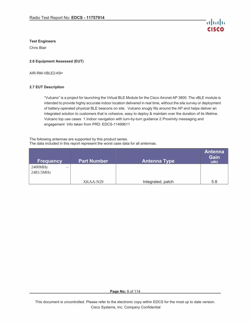
Test Engineers
Chris Blair
2.6 Equipment Assessed (EUT) AIR-RM-VBLE2-K9=
2.7 EUT Description
“Vulcano” is a project for launching the Virtual BLE Module for the Cisco Aironet AP 3800. The vBLE module is intended to provide highly accurate indoor location delivered in real time, without the site survey or deployment of battery-operated physical BLE beacons on site. Vulcano snugly fits around the AP and helps deliver an integrated solution to customers that is cohesive, easy to deploy & maintain over the duration of its lifetime. Vulcano top use cases 1. Indoor navigation with turn-by-turn guidance 2. Proximity messaging and engagement Info taken from PRD: EDCS-11499611
The following antennas are supported by this product series. The data included in this report represent the worst case data for all antennas.
Frequency Part Number Antenna Type
Antenna Gain (dBi)
2400MHz – 2483.5MHz
XKAA-N29 Integrated, patch 5.8

Radio Test Report No: EDCS - 11757914
Page No: 9 of 114
This document is uncontrolled. Please refer to the electronic copy within EDCS for the most up to date version. Cisco Systems, Inc. Company Confidential
Section 3: Result Summary
3.1 Results Summary Table Conducted emissions
BasicStandard
Technical Requirements / Details Result
FCC 15.247 RSS-247
6dB Bandwidth Systems using digital modulation techniques may operate in the 2400-2483.5MHz band. The minimum 6dB bandwidth shall be at least 500 kHz
Pass
FCC 15.247 RSS-247
99% & 26 dB Bandwidth: The 99% occupied bandwidth is the frequency bandwidth such that, below its lower and above its upper frequency limits, the mean powers are each equal to 0.5% of the total mean power of the given emission. There is no limit for 99% OBW. The 26 dB emission is the width of the emission that is constrained by the frequencies associated with the two outermost amplitude points (upper and lower frequencies) that are attenuated by 26 dB relative to the maximum level measured in the fundamental emission.
Pass
FCC 15.247 RSS-247
Output Power: 15.247 The maximum conducted output power of the intentional radiator for systems using digital modulation in the 2400-2483.5 MHz band shall not exceed 1 Watt (30dBm). If transmitting antennas of directional gain greater than 6 dBi are used, the maximum conducted output power shall be reduced by the amount in dB that the directional gain of the antenna exceeds 6 dBi. RSS-247 For DTSs employing digital modulation techniques operating in the band 2400-2483.5 MHz, the maximum peak conducted output power shall not exceed 1W. Except as provided in Section 5.4(e), the e.i.r.p. shall not exceed 4 W.
Pass
FCC 15.247 RSS-247
Power Spectral Density For digitally modulated systems, the power spectral density conducted from the intentional radiator to the antenna shall not be greater than 8 dBm in any 3 kHz band during any time interval of continuous transmission.
Pass

Radio Test Report No: EDCS - 11757914
Page No: 10 of 114
This document is uncontrolled. Please refer to the electronic copy within EDCS for the most up to date version. Cisco Systems, Inc. Company Confidential
FCC 15.247 RSS-247
Conducted Spurious Emissions / Band-Edge: In any 100 kHz bandwidth outside the frequency band in which the spread spectrum or digitally modulated device is operating, the RF power that is produced shall be at least 20 dB below that in the 100 kHz bandwidth within the band that contains the highest level of the desired power, based on either an RF conducted or a radiated measurement, provided that the transmitter demonstrates compliance with the peak conducted power limits. If the transmitter complies with the conducted power limits based on the use of root-mean-square averaging over a time interval, as permitted under section 5.4(d), the attenuation required shall be 30 dB instead of 20 dB. Attenuation below the general field strength limits specified in RSS-Gen is not required.
Pass
FCC 15.247 RSS-247 FCC 15.205 RSS-Gen
Restricted band: Unwanted emissions falling within the restricted bands, as defined in FCC 15.205 (a) and RSS-Gen 8.10 must also comply with the radiated emission limits specified in FCC 15.209 (a) and RSS-Gen 8.9
Pass
Radiated Emissions (General requirements)
Basic Standard Technical Requirements / Details Result
FCC 15.209 RSS-Gen
TX Spurious Emissions: Except as provided elsewhere in this subpart, the emissions from an intentional radiator shall not exceed the field strength levels specified in the filed strength limits table in this section. Unwanted emissions falling within the restricted bands, as defined in FCC 15.205 (a) and RSS-Gen 8.10 must also comply with the radiated emission limits specified in FCC 15.209 (a) and RSS-Gen 8.9
Pass
RSS-Gen RX Spurious Emissions: RSS-Gen 8.9 Except when the requirements applicable to a given device state otherwise, emissions from licence-exempt transmitters shall comply with the field strength limits shown in Table 4 and Table 5 below. Additionally, the level of any transmitter emission shall not exceed the level of the transmitter’s fundamental emission. RSS-Gen 8.10 Restricted Bands Unwanted emissions that fall into restricted bands of Table 6 shall comply with the limits specified in RSS-Gen; and (c ) Unwanted emissions that do not fall within the restricted frequency bands of Table 6 shall comply either with the limits specified in the applicable RSS or with those specified in this RSS-Gen.
Pass
FCC 15.207 RSS-Gen
AC conducted Emissions: Except when the requirements applicable to a given device state otherwise, for any radio apparatus equipped to operate from the public utility AC power supply, either directly or indirectly (such as with a battery charger), the radio frequency voltage of emissions conducted back onto the AC power lines in the frequency range of 0.15 MHz to 30 MHz shall not exceed the limits shown in the table in these sections. The more stringent limit applies at the frequency range boundaries.
Pass

Radio Test Report No: EDCS - 11757914
Page No: 11 of 114
This document is uncontrolled. Please refer to the electronic copy within EDCS for the most up to date version. Cisco Systems, Inc. Company Confidential

Radio Test Report No: EDCS - 11757914
Page No: 12 of 114
This document is uncontrolled. Please refer to the electronic copy within EDCS for the most up to date version. Cisco Systems, Inc. Company Confidential
Section 4: Sample Details
Note: Each sample was evaluated to ensure that its condition was suitable to be used as a test sample prior to the commencement of testing. Please also refer to the “Justification for worst Case test Configuration” section of this report for further details on the selection of EUT samples.
4.1 Sample Details
Sample No.
Equipment Details Manufacturer
Hardware Rev. Firmware Rev. Software Rev. Serial Number
S01 AIR-RM-VBLE2-K9= WNC 20 apfw-0.1.11711-master-94b1
2017-08-03_00:19:33_UTC
KWC2121083K
S02 AIR-AP3802E-B-K9 Cisco 068-100532-01 2.4.18 = NSS FW ver.
8.5.107.2 FOC20310WKV
S03 ADP-48DR BC LPS Delta 341-100460-01 NA NA DAB2016S1HV S04 AIR-RM-VBLE2-K9= WNC 20 apfw-0.1.11711-m
aster-94b1 2017-08-03_00:19:33_UTC
KWC2120068S
S05 AIR-RM-VBLE2-K9= WNC 20 apfw-0.1.11711-master-94b1
2017-08-03_00:19:33_UTC
KWC21210855
S06 ADP-48DR BC
Delta 341-100460-01
NA NA DAB2016S1JD
S07 AIR-AP3802E-B-K9
Cisco 068-100532-01 2.4.18 = NSS FW ver.
8.5.107.2 FOC20310W7Q
4.2 System Details
System # Description Samples 1 Radio Conducted Emissions Tests S01, S02, S03 2 RSE S04, S02, S03 3 AC Conducted Emissons S05, S06, S07 4.3 Mode of Operation Details
Mode# Description Comments1 Continuous Transmitting,
Conducted Tests Continuous transmit. 62.4% duty cycle. 390us on, 235us off, regular. BLE (GFSK). See Appendix J for details.
2 Continuous Transmitting, Radiated Tests
Continuous transmit. 87.5% duty cycle. 1094us on, 156us off, regular. BLE (GFSK). See Appendix J for details.
Radio Test Report No: EDCS - 11757914
Page No: 13 of 114
This document is uncontrolled. Please refer to the electronic copy within EDCS for the most up to date version. Cisco Systems, Inc. Company Confidential
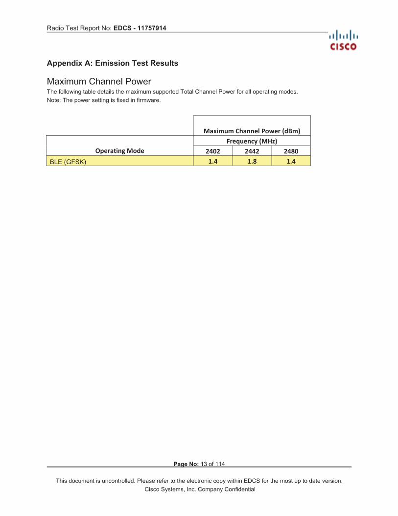
Appendix A: Emission Test Results Maximum Channel Power The following table details the maximum supported Total Channel Power for all operating modes. Note: The power setting is fixed in firmware.
Maximum Channel Power (dBm)Frequency (MHz)
Operating Mode 2402 2442 2480BLE (GFSK) 1.4 1.8 1.4

Radio Test Report No: EDCS - 11757914
Page No: 14 of 114
This document is uncontrolled. Please refer to the electronic copy within EDCS for the most up to date version. Cisco Systems, Inc. Company Confidential
A.1 Duty Cycle
Duty Cycle Test Requirement From KDB 558074, Section 6
6.0 Duty cycle, transmission duration and maximum power control level Preferably, all measurements of maximum conducted (average) output power will be performed with the EUT transmitting continuously (i.e., with a duty cycle of greater than or equal to 98%). When continuous operation cannot be realized, then the use of sweep triggering/signal gating techniques can be utilized to ensure that measurements are made only during transmissions at the maximum power control level. … When continuous transmission cannot be achieved and sweep triggering/signal gating cannot be implemented, alternate procedures are provided that can be used to measure the average power; however, they will require an additional measurement of the transmitter duty cycle. Within this guidance document, the duty cycle refers to the fraction of time over which the transmitter is on and is transmitting at its maximum power control level. The duty cycle is considered to be constant if variations are less than ± 2 percent, otherwise the duty cycle is considered to be non-constant.
Duty Cycle Test Method From KDB 558074, Section 6:
The zero-span mode on a spectrum analyzer or EMI receiver if the response time and spacing between bins on the sweep are sufficient to permit accurate measurements of the on and off times of the transmitted signal. Set the center frequency of the instrument to the center frequency of the transmission. Set RBW OBW if possible; otherwise, set RBW to the largest available value. Set VBW RBW. Set detector = peak or average. The zero-span measurement method shall not be used unless both RBW and VBW are > 50/T and the number of sweep points across duration T exceeds 100. (For example, if VBW and/or RBW are limited to 3 MHz, then the zero-span method of measuring duty cycle shall not be used if T 16.7 microseconds.)
Duty Cycle Test Information Tested By : Chris Blair
Date of testing:
August 8, 2017
Test Result : Duty cycle = 62.4% Test Equipment See Appendix C for list of test equipment Samples, Systems, and Modes System Number
Description Samples System under test
Support equipment
1 EUT S01 Support S02, S03

Radio Test Report No: EDCS - 11757914
Page No: 15 of 114
This document is uncontrolled. Please refer to the electronic copy within EDCS for the most up to date version. Cisco Systems, Inc. Company Confidential
Duty Cycle Data Table Duty Cycle table and screen captures are shown below for power/psd modes. Channel
ModeDataRate
On time(ms) Total Time (ms)
Duty Cycle(%)
Correction Factor (dB) =10*log (1/x), where x = dutycycle
2402 BLE (GFSK) 1Mbps .390 .625 62.4% 10*log (1/.624) = +2.05dB2442 BLE (GFSK) 1Mbps .390 .625 62.4% 10*log (1/.624) = +2.05dB2480 BLE (GFSK) 1Mbps .390 .625 62.4% 10*log (1/.624) = +2.05dB
Duty Cycle Data Screenshots

Radio Test Report No: EDCS - 11757914
Page No: 16 of 114
This document is uncontrolled. Please refer to the electronic copy within EDCS for the most up to date version. Cisco Systems, Inc. Company Confidential

Radio Test Report No: EDCS - 11757914
Page No: 17 of 114
This document is uncontrolled. Please refer to the electronic copy within EDCS for the most up to date version. Cisco Systems, Inc. Company Confidential

Radio Test Report No: EDCS - 11757914
Page No: 18 of 114
This document is uncontrolled. Please refer to the electronic copy within EDCS for the most up to date version. Cisco Systems, Inc. Company Confidential

Radio Test Report No: EDCS - 11757914
Page No: 19 of 114
This document is uncontrolled. Please refer to the electronic copy within EDCS for the most up to date version. Cisco Systems, Inc. Company Confidential

Radio Test Report No: EDCS - 11757914
Page No: 20 of 114
This document is uncontrolled. Please refer to the electronic copy within EDCS for the most up to date version. Cisco Systems, Inc. Company Confidential

Radio Test Report No: EDCS - 11757914
Page No: 21 of 114
This document is uncontrolled. Please refer to the electronic copy within EDCS for the most up to date version. Cisco Systems, Inc. Company Confidential
A.2 6dB Bandwidth 6dB Bandwidth Test Requirement
For the FCC: 15.247 (2)
Systems using digital modulation techniques may operate in the 902–928 MHz, 2400–2483.5 MHz, and 5725–5850 MHz bands. The minimum 6 dB bandwidth shall be at least 500 kHz.
For Industry Canada: RSS-247 5.2 (a)
5.2 Digital transmission systems DTSs include systems that employ digital modulation techniques resulting in spectral characteristics similar to direct sequence systems. The following applies to the bands 902-928 MHz and 2400-2483.5 MHz: a) The minimum 6 dB bandwidth shall be 500 kHz.
6dB Bandwidth Test Procedure
Ref. KDB 558074 D01 DTS Meas Guidance v04, 8.2 Option 2 ANSI C63.10: 2013 6dB BWTest Procedure 1. Set the radio in the continuous transmitting mode. 2. Allow the trace to stabilize. 3. Setting the x-dB bandwidth mode to -6dB within the measurement set up function. 4. Select the automatic OBW measurement function of an instrument to perform bandwidth measurement. 5. Capture graphs and record pertinent measurement data.
Ref. KDB 558074 D01 DTS Meas Guidance v04, 8.2 Option 2 ANSI C63.10: 2013 section 11.8.2 Option 2 6dB BWTest parameters

Radio Test Report No: EDCS - 11757914
Page No: 22 of 114
This document is uncontrolled. Please refer to the electronic copy within EDCS for the most up to date version. Cisco Systems, Inc. Company Confidential
Samples, Systems, and Modes System Number
Description Samples System under test
Support equipment
1 EUT S01 Support S02, S03
Tested By : Chris Blair
Date of testing:
August 8, 2017
Test Result : PASS Test Equipment See Appendix C for list of test equipment 6dB Bandwidth Data Table
Frequency (MHz) Mode
Data Rate (Mbps) 6dB BW (kHz) Minimum (kHz)
Margin (kHz)
2402 BLE (GFSK) 1 721.4 500 221.4 2442 BLE (GFSK) 1 728.3 500 228.3 2480 BLE (GFSK) 1 726.6 500 226.6

Radio Test Report No: EDCS - 11757914
Page No: 23 of 114
This document is uncontrolled. Please refer to the electronic copy within EDCS for the most up to date version. Cisco Systems, Inc. Company Confidential
6dB Bandwidth, 2402 MHz, 1Mbps, GFSK

Radio Test Report No: EDCS - 11757914
Page No: 24 of 114
This document is uncontrolled. Please refer to the electronic copy within EDCS for the most up to date version. Cisco Systems, Inc. Company Confidential
6dB Bandwidth, 2442 MHz, 1Mbps, GFSK

Radio Test Report No: EDCS - 11757914
Page No: 25 of 114
This document is uncontrolled. Please refer to the electronic copy within EDCS for the most up to date version. Cisco Systems, Inc. Company Confidential
6dB Bandwidth, 2480 MHz, 1Mbps, GFSK

Radio Test Report No: EDCS - 11757914
Page No: 26 of 114
This document is uncontrolled. Please refer to the electronic copy within EDCS for the most up to date version. Cisco Systems, Inc. Company Confidential
A.3 Occupied Bandwidth Occupied Bandwidth Test Requirement The 99% occupied bandwidth is the frequency bandwidth such that, below its lower and above its upper frequency limits, the mean powers are each equal to 0.5% of the total mean power of the given emission. There is no limit for 99% OBW. The 26 dB emission is the width of the emission that is constrained by the frequencies associated with the two outermost amplitude points (upper and lower frequencies) that are attenuated by 26 dB relative to the maximum level measured in the fundamental emission.
Occupied Bandwidth Test Method
Ref. ANSI C63.10: 2013 26 BW & 99% BW Test Procedure 1. Set the radio in the continuous transmitting mode. 2. Allow the trace to stabilize. 3. Setting the x-dB bandwidth mode to -26dB & OBW to 99% within the measurement set up function. 4. Select the automatic OBW measurement function of an instrument to perform bandwidth measurement. 5. Capture graphs and record pertinent measurement data.
Ref. ANSI C63.10: 2013 section 6.9.3 26 BW & 99% BW Test parameters

Radio Test Report No: EDCS - 11757914
Page No: 27 of 114
This document is uncontrolled. Please refer to the electronic copy within EDCS for the most up to date version. Cisco Systems, Inc. Company Confidential
Samples, Systems, and Modes System Number
Description Samples System under test
Support equipment
1 EUT S01 Support S02, S03
Tested By : Chris Blair
Date of testing:
August 8, 2017
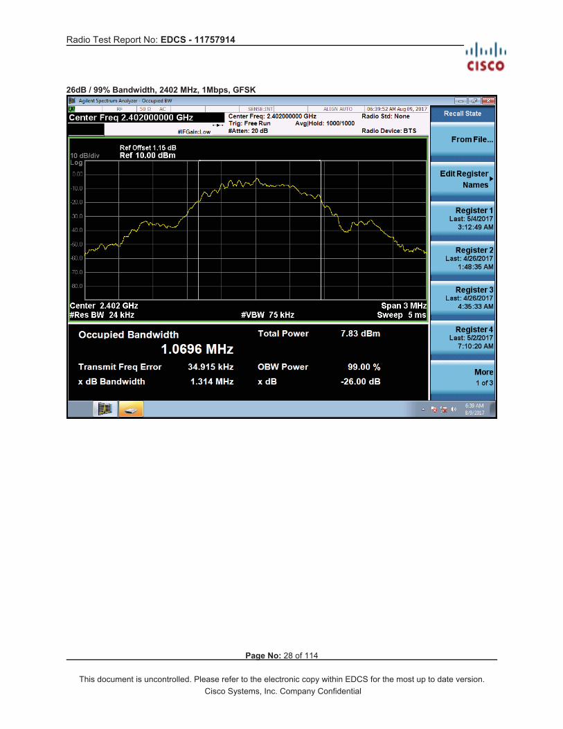
Test Result : PASS Test Equipment See Appendix C for list of test equipment Occupied Bandwidth Data Table
Frequency (MHz) Mode
Data Rate (Mbps)
26dB BW (MHz)
99% BW (MHz)
2402 BLE (GFSK) 1 1.314 1.07 2442 BLE (GFSK) 1 1.317 1.07 2480 BLE (GFSK) 1 1.319 1.07
Radio Test Report No: EDCS - 11757914
Page No: 28 of 114
This document is uncontrolled. Please refer to the electronic copy within EDCS for the most up to date version. Cisco Systems, Inc. Company Confidential
26dB / 99% Bandwidth, 2402 MHz, 1Mbps, GFSK

Radio Test Report No: EDCS - 11757914
Page No: 29 of 114
This document is uncontrolled. Please refer to the electronic copy within EDCS for the most up to date version. Cisco Systems, Inc. Company Confidential
26dB / 99% Bandwidth, 2442 MHz, 1Mbps, GFSK

Radio Test Report No: EDCS - 11757914
Page No: 30 of 114
This document is uncontrolled. Please refer to the electronic copy within EDCS for the most up to date version. Cisco Systems, Inc. Company Confidential
26dB / 99% Bandwidth, 2480 MHz, 1Mbps, GFSK

Radio Test Report No: EDCS - 11757914
Page No: 31 of 114
This document is uncontrolled. Please refer to the electronic copy within EDCS for the most up to date version. Cisco Systems, Inc. Company Confidential
A.4 Maximum Conducted Output Power Maximum Conducted Output Power Test Requirement FCC, 15.247: (b) The maximum peak conducted output power of the intentional radiator shall not exceed the following: (3) For systems using digital modulation in the 902-928 MHz, 2400-2483.5 MHz, and 5725-5850 MHz bands: 1 Watt. As an alternative to a peak power measurement, compliance with the one Watt limit can be based on a measurement of the maximum conducted output power. Maximum Conducted Output Power is defined as the total transmit power delivered to all antennas and antenna elements averaged across all symbols in the signaling alphabet when the transmitter is operating at its maximum power control level. Power must be summed across all antennas and antenna elements. The average must not include any time intervals during which the transmitter is off or is transmitting at a reduced power level. If multiple modes of operation are possible (e.g., alternative modulation methods), the maximum conducted output power is the highest total transmit power occurring in any mode. (4) The conducted output power limit specified in paragraph (b) of this section is based on the use of antennas with directional gains that do not exceed 6 dBi. Except as shown in paragraph (c) of this section, if transmitting antennas of directional gain greater than 6 dBi are used, the conducted output power from the intentional radiator shall be reduced below the stated values in paragraphs (b)(1), (b)(2), and (b)(3) of this section, as appropriate, by the amount in dB that the directional gain of the antenna exceeds 6 dBi. Industry Canada, RSS-247:
5.4 Transmitter output power and equivalent isotropically radiated power (e.i.r.p.) requirements d) For DTSs employing digital modulation techniques operating in the bands 902-928 MHz and 2400-2483.5 MHz, the maximum peak conducted output power shall not exceed 1W. The e.i.r.p. shall not exceed 4 W, except as provided in section 5.4(e).
As an alternative to a peak power measurement, compliance can be based on a measurement of the maximum conducted output power. The maximum conducted output power is the total transmit power delivered to all antennas and antenna elements, averaged across all symbols in the signalling alphabet when the transmitter is operating at its maximum power control level. Power must be summed across all antennas and antenna elements. The average must not include any time intervals during which the transmitter is off or transmitting at a reduced power level. If multiple modes of operation are implemented, the maximum conducted output power is the highest total transmit power occurring in any mode.
Maximum Conducted Output Power Test Method Ref. KDB 558074 D01 DTS Meas Guidance v04 ANSI C63.10: 2013 Maximum Conducted Output power Test Procedure 1. Set the radio in the continuous transmitting mode at full power 2. Compute power by integrating the spectrum across the EBW (or alternatively entire 99% OBW) of the signal using the instrument’s band power measurement function. The integration shall be performed using the spectrum analyzer band-power measurement function with band limits set equal to the EBW or the OBW band edges.
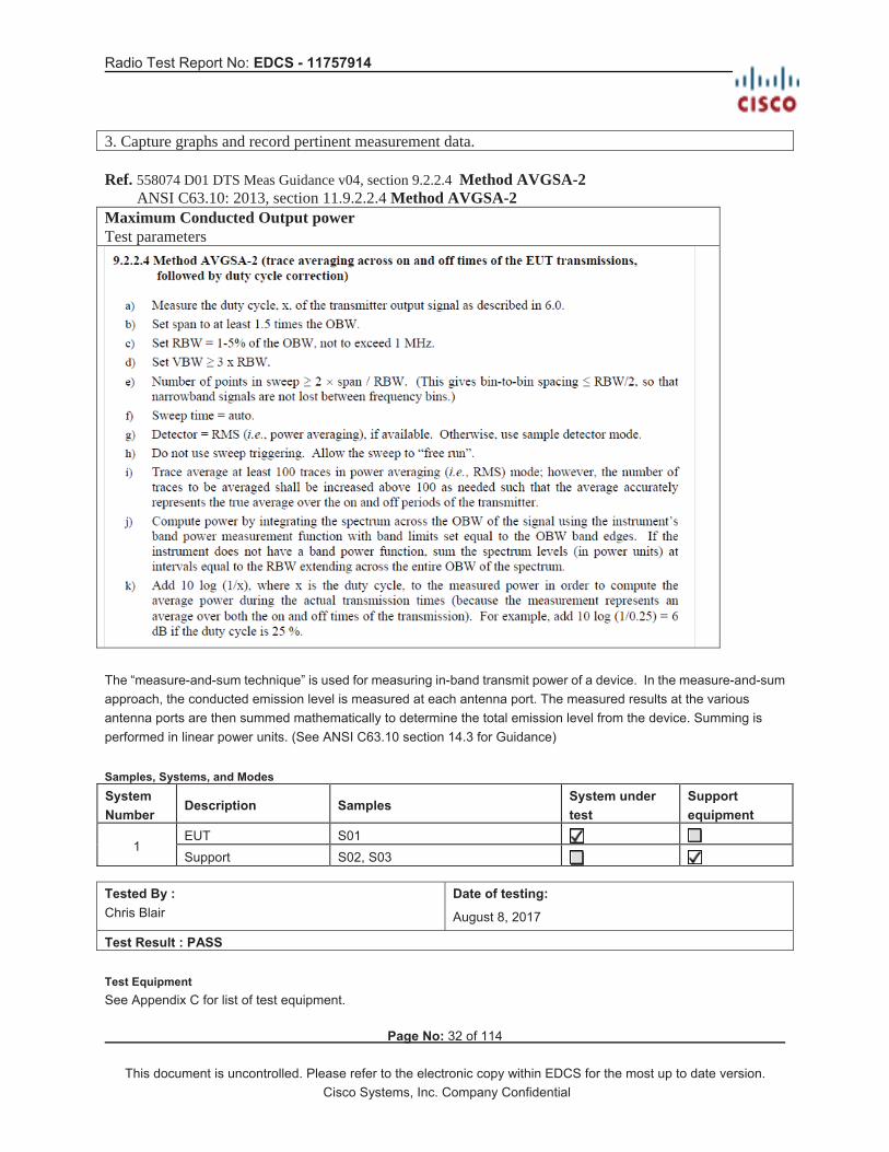
Radio Test Report No: EDCS - 11757914
Page No: 32 of 114
This document is uncontrolled. Please refer to the electronic copy within EDCS for the most up to date version. Cisco Systems, Inc. Company Confidential
3. Capture graphs and record pertinent measurement data.
Ref. 558074 D01 DTS Meas Guidance v04, section 9.2.2.4 Method AVGSA-2 ANSI C63.10: 2013, section 11.9.2.2.4 Method AVGSA-2 Maximum Conducted Output power Test parameters
The “measure-and-sum technique” is used for measuring in-band transmit power of a device. In the measure-and-sum approach, the conducted emission level is measured at each antenna port. The measured results at the various antenna ports are then summed mathematically to determine the total emission level from the device. Summing is performed in linear power units. (See ANSI C63.10 section 14.3 for Guidance)
Samples, Systems, and Modes System Number
Description Samples System under test
Support equipment
1 EUT S01 Support S02, S03
Tested By : Chris Blair
Date of testing:
August 8, 2017
Test Result : PASS Test Equipment See Appendix C for list of test equipment.

Radio Test Report No: EDCS - 11757914
Page No: 33 of 114
This document is uncontrolled. Please refer to the electronic copy within EDCS for the most up to date version. Cisco Systems, Inc. Company Confidential
Maximum Conducted Output Power Data Table
Freq
uenc
y (M
Hz)
Mode Tx
Pat
hs
Cor
rela
ted
Ant
enna
Gai
n (d
Bi)
Dut
y C
ycle
(%)
Cor
rect
ion
Fact
or (d
B)
= 10
*log
(1/x
) whe
re x
= d
uty
cycl
e
Tx 1
Max
Pow
er (d
Bm
)
Tx 2
Max
Pow
er (d
Bm
)
Tx 3
Max
Pow
er (d
Bm
)
Tx 4
Max
Pow
er (d
Bm
)
Tota
l Tx
Cha
nnel
Pow
er (d
Bm
)
Tota
l TX
Cha
nnel
Pow
er (d
Bm
),
corr
ecte
d fo
r dut
y cy
cle
Lim
it (d
Bm
)
Mar
gin
(dB
)
2402 BLE(GFSK) 1 5.8 62.4% +2.05 0.68 0.68 +1.37 30 28.63
2442 BLE(GFSK) 1 5.8 62.4% +2.05 0.24 0.24 +1.81 30 28.19
2480 BLE(GFSK) 1 5.8 62.4%
+2.050.62 0.62 +1.43 30 28.57

Radio Test Report No: EDCS - 11757914
Page No: 34 of 114
This document is uncontrolled. Please refer to the electronic copy within EDCS for the most up to date version. Cisco Systems, Inc. Company Confidential
Maximum Conducted Output Power, 2402 MHz, 1Mbps, GFSK

Radio Test Report No: EDCS - 11757914
Page No: 35 of 114
This document is uncontrolled. Please refer to the electronic copy within EDCS for the most up to date version. Cisco Systems, Inc. Company Confidential
Maximum Conducted Output Power, 2442 MHz, 1Mbps, GFSK

Radio Test Report No: EDCS - 11757914
Page No: 36 of 114
This document is uncontrolled. Please refer to the electronic copy within EDCS for the most up to date version. Cisco Systems, Inc. Company Confidential
Maximum Conducted Output Power, 2480 MHz, 1Mbps, GFSK
Radio Test Report No: EDCS - 11757914
Page No: 37 of 114
This document is uncontrolled. Please refer to the electronic copy within EDCS for the most up to date version. Cisco Systems, Inc. Company Confidential
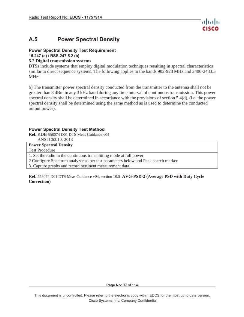
A.5 Power Spectral Density Power Spectral Density Test Requirement 15.247 (e) / RSS-247 5.2 (b) 5.2 Digital transmission systems DTSs include systems that employ digital modulation techniques resulting in spectral characteristics similar to direct sequence systems. The following applies to the bands 902-928 MHz and 2400-2483.5 MHz: b) The transmitter power spectral density conducted from the transmitter to the antenna shall not be greater than 8 dBm in any 3 kHz band during any time interval of continuous transmission. This power spectral density shall be determined in accordance with the provisions of section 5.4(d), (i.e. the power spectral density shall be determined using the same method as is used to determine the conducted output power). Power Spectral Density Test Method Ref. KDB 558074 D01 DTS Meas Guidance v04 ANSI C63.10: 2013 Power Spectral Density Test Procedure 1. Set the radio in the continuous transmitting mode at full power 2.Configure Spectrum analyzer as per test parameters below and Peak search marker 3. Capture graphs and record pertinent measurement data.
Ref. 558074 D01 DTS Meas Guidance v04, section 10.5 AVG-PSD-2 (Average PSD with Duty Cycle Correction)

Radio Test Report No: EDCS - 11757914
Page No: 38 of 114
This document is uncontrolled. Please refer to the electronic copy within EDCS for the most up to date version. Cisco Systems, Inc. Company Confidential
Power Spectral Density Test parameters
The “Measure and add 10 log(N) dB technique”, where N is the number of outputs, is used for measuring in-band Power Spectral Density. With this technique, spectrum measurements are performed at each output of the device, and the quantity 10 log(4) (or 6dB) is added to the worst case spectrum value before comparing to the emission limit. (See ANSI C63.10 section 14.3.2.3 ) Samples, Systems, and Modes System Number
Description Samples System under test
Support equipment
1 EUT S01 Support S02, S03
Tested By : Chris Blair
Date of testing:
August 8, 2017
Test Result : PASS Test Equipment See Appendix C for list of test equipment

Radio Test Report No: EDCS - 11757914
Page No: 39 of 114
This document is uncontrolled. Please refer to the electronic copy within EDCS for the most up to date version. Cisco Systems, Inc. Company Confidential
Power Spectral Density Data Table
Freq
uenc
y (M
Hz)
Mode
Tx P
aths
Cor
rela
ted
Ant
enna
Gai
n (d
Bi)
Dut
y C
ycle
(%)
Cor
rect
ion
Fact
or (d
B)
= 10
*log
(1/x
) whe
re x
= d
uty
cycl
e
Tx 1
PSD
(dB
m/3
kHz)
Tx 2
PSD
(dB
m/3
kHz)
Tx 3
PSD
(dB
m/3
kHz)
Tx 4
PSD
(dB
m/3
kHz)
Hig
hest
PSD
val
ue p
er a
nten
na
(dB
m/3
kHz)
, cor
rect
ed fo
r dut
y cy
cle.
Tota
l PSD
(dB
m/3
kHz)
1
Lim
it (d
Bm
/3kH
z)
Mar
gin
(dB
)
2402 BLE(GFSK) 1 5.8 62.4%
+2.0515.085 13.035 13.035 8 21.035
2442 BLE(GFSK) 1 5.8 62.4%
+2.0514.000 11.950 11.950 8 19.950
2480 BLE(GFSK) 1 5.8 62.4%
+2.0514.469 12.419 12.419 8 20.419
1 PSD is presented in dBm/10kHz, per the test method cited. This is conservative and < the PSD in dBm/3kHz.

Radio Test Report No: EDCS - 11757914
Page No: 40 of 114
This document is uncontrolled. Please refer to the electronic copy within EDCS for the most up to date version. Cisco Systems, Inc. Company Confidential
Power Spectral Density, 2402 MHz, 1Mbps, GFSK

Radio Test Report No: EDCS - 11757914
Page No: 41 of 114
This document is uncontrolled. Please refer to the electronic copy within EDCS for the most up to date version. Cisco Systems, Inc. Company Confidential
Power Spectral Density, 2442 MHz, 1Mbps, GFSK

Radio Test Report No: EDCS - 11757914
Page No: 42 of 114
This document is uncontrolled. Please refer to the electronic copy within EDCS for the most up to date version. Cisco Systems, Inc. Company Confidential
Power Spectral Density, 2480 MHz, 1Mbps, GFSK

Radio Test Report No: EDCS - 11757914
Page No: 43 of 114
This document is uncontrolled. Please refer to the electronic copy within EDCS for the most up to date version. Cisco Systems, Inc. Company Confidential
A.6 Conducted Spurious Emissions Conducted Spurious Emissions Test Requirement 15.205 / RSS-Gen Radiated emissions which fall in the restricted bands, as defined in Section 15.205(a) and RSS-GEN section 8.10, must also comply with the radiated emission limits specified in Section 15.209(a) (see Section 15.205(c)) and RSS-Gen section 8.9 RSS-Gen 8.9 Except when the requirements applicable to a given device state otherwise, emissions from licence-exempt transmitters shall comply with the field strength limits shown in Table 4 and Table 5 below. Additionally, the level of any transmitter emission shall not exceed the level of the transmitter’s fundamental emission. RSS-Gen 8.10��b��Unwanted emissions that fall into restricted bands of Table 6 shall comply with the limits specified in RSS-Gen; and (c ) Unwanted emissions that do not fall within the restricted frequency bands of Table 6 shall comply either with the limits specified in the applicable RSS or with those specified in this RSS-Gen. Conducted Spurious Emissions Test Method Ref. KDB 558074 D01 DTS Meas Guidance v04 ANSI C63.10: 2013 Conducted Spurious Emissions Test Procedure 1. Connect the antenna port(s) to the spectrum analyzer input. 2. Place the radio in continuous transmit mode 3. Configure Spectrum analyzer as per test parameters below (be sure to enter all losses between the transmitter output and the spectrum analyzer). 4. Use the marker function to determine the maximum spurs amplitude level. 5. The “measure-and-sum technique” is used for measuring in-band transmit power of a device. In the measure-and-sum approach, the conducted emission level is measured at each antenna port. The measured results at the various antenna ports are then summed mathematically to determine the total emission level from the device. Summing is performed in linear power units. The worst case output is recorded. (see ANSI C63.10 2013 section 14.3.2.2 ) 6. Capture graphs and record pertinent measurement data.
Ref. 558074 D01 DTS Meas Guidance v04 section 11.1b, 11.2-3, 12.2.4 & 12.2.5.3 ANSI C63.10: 2013 section 11.10.3 & 11.12.2.4 & 11.12.2.5.3 Conducted Spurious Emissions Test parameters Span = 30 MHz-18GHz / 18GHz –Tenth Harmonic RBW = 1 MHz VBW 3 x RBW for Peak, 1kHz for Average Sweep = Auto couple Detector = Peak Trace = Max Hold. KDB 558074 D01 DTS Meas Guidance v04 section 12.2.2 © add the max antenna gain + ground reflection factor (4.7 dB for frequencies between 30 MHz and 1000 MHz, and 0 dB for frequencies > 1000 MHz).

Radio Test Report No: EDCS - 11757914
Page No: 44 of 114
This document is uncontrolled. Please refer to the electronic copy within EDCS for the most up to date version. Cisco Systems, Inc. Company Confidential
Samples, Systems, and Modes System Number
Description Samples System under test
Support equipment
EUT S01 Support S02, S03
Tested By : Chris Blair
Dates of testing:
August 15, 2017 & September 19-20, 2017
Test Result : PASS Test Equipment See Appendix C for list of test equipment Conducted Spurious Emissions Data Table - Peak
Freq
uenc
y (M
Hz)
Mode Tx P
aths
Cor
rela
ted
Ant
enna
Gai
n
(dB
i)
Tx 1
Spu
r Pow
er (d
Bm
)
Tota
l Con
duct
ed S
pur
(dB
m) =
Tx
1 Sp
ur p
ower
(d
Bm
) + A
nten
na G
ain
(dB
i) +
Gro
und
Ref
lect
ion
Fact
or (d
B),
if ap
plic
albl
e.
Lim
it (d
Bm
)
Mar
gIn
(dB
)
2402 BLE (GFSK) 1 5.8 51.39 45.59 21.25 24.342442 BLE (GFSK) 1 5.8 49.50 43.70 21.25 22.452480 BLE (GFSK) 1 5.8 47.83 42.03 21.25 20.78
Conducted Spurious Emissions Data Table – Average *Separate average measurements (RBW=1kHz) not performed, since peak measurements were under average limits for average (-41.25dBm).
Freq
uenc
y (M
Hz)
Mode Tx P
aths
Cor
rela
ted
Ant
enna
G
ain
(dB
i)
Tx 1
Spu
r Pow
er
(dB
m)*
Tota
l Con
duct
ed S
pur
(dB
m)
Lim
it (d
Bm
)
Mar
gIn
(dB
)
2402 BLE (GFSK) 1 5.8 51.39 45.59 41.25 4.342442 BLE (GFSK) 1 5.8 49.50 43.70 41.25 2.452480 BLE (GFSK) 1 5.8 47.83 42.03 41.25 0.78

Radio Test Report No: EDCS - 11757914
Page No: 45 of 114
This document is uncontrolled. Please refer to the electronic copy within EDCS for the most up to date version. Cisco Systems, Inc. Company Confidential
Conducted Spurs Peak, 1-18GHz, 2402MHz, BLE (GFSK) 5.8dBi antenna gain reflected in limit line: -41.25dBm (avg limit) – 5.8dBi = -47.05dBm.

Radio Test Report No: EDCS - 11757914
Page No: 46 of 114
This document is uncontrolled. Please refer to the electronic copy within EDCS for the most up to date version. Cisco Systems, Inc. Company Confidential
Conducted Spurs Peak, 1-18GHz, 2442MHz, BLE (GFSK) 5.8dBi antenna gain reflected in limit line: -41.25dBm (avg limit) – 5.8dBi = -47.05dBm.

Radio Test Report No: EDCS - 11757914
Page No: 47 of 114
This document is uncontrolled. Please refer to the electronic copy within EDCS for the most up to date version. Cisco Systems, Inc. Company Confidential
Conducted Spurs Peak, 1-18GHz, 2480MHz, BLE (GFSK) 5.8dBi antenna gain reflected in limit line: -41.25dBm (avg limit) – 5.8dBi = -47.05dBm.

Radio Test Report No: EDCS - 11757914
Page No: 48 of 114
This document is uncontrolled. Please refer to the electronic copy within EDCS for the most up to date version. Cisco Systems, Inc. Company Confidential
Conducted Spurs Peak, 18-26GHz, 2402MHz, BLE (GFSK) 5.8dBi antenna gain reflected in limit line: -41.25dBm (avg limit) – 5.8dBi = -47.05dBm.

Radio Test Report No: EDCS - 11757914
Page No: 49 of 114
This document is uncontrolled. Please refer to the electronic copy within EDCS for the most up to date version. Cisco Systems, Inc. Company Confidential
Conducted Spurs Peak, 18-26GHz, 2442MHz, BLE (GFSK) 5.8dBi antenna gain reflected in limit line: -41.25dBm (avg limit) – 5.8dBi = -47.05dBm.

Radio Test Report No: EDCS - 11757914
Page No: 50 of 114
This document is uncontrolled. Please refer to the electronic copy within EDCS for the most up to date version. Cisco Systems, Inc. Company Confidential
Conducted Spurs Peak, 18-26GHz, 2480MHz, BLE (GFSK) 5.8dBi antenna gain reflected in limit line: -41.25dBm (avg limit) – 5.8dBi = -47.05dBm.

Radio Test Report No: EDCS - 11757914
Page No: 51 of 114
This document is uncontrolled. Please refer to the electronic copy within EDCS for the most up to date version. Cisco Systems, Inc. Company Confidential
Conducted Spurs Peak, 30M-1GHz, 2402MHz, BLE (GFSK) 5.8dBi antenna gain and 4.7dB ground reflection factor reflected in limit line: -41.25dBm (avg limit) – 5.8dBi – 4.7dB = -51.75dBm.

Radio Test Report No: EDCS - 11757914
Page No: 52 of 114
This document is uncontrolled. Please refer to the electronic copy within EDCS for the most up to date version. Cisco Systems, Inc. Company Confidential
Conducted Spurs Peak, 30M-1GHz, 2442MHz, BLE (GFSK) 5.8dBi antenna gain and 4.7dB ground reflection factor reflected in limit line: -41.25dBm (avg limit) – 5.8dBi – 4.7dB = -51.75dBm.

Radio Test Report No: EDCS - 11757914
Page No: 53 of 114
This document is uncontrolled. Please refer to the electronic copy within EDCS for the most up to date version. Cisco Systems, Inc. Company Confidential
Conducted Spurs Peak, 30M-1GHz, 2480MHz, BLE (GFSK) 5.8dBi antenna gain and 4.7dB ground reflection factor reflected in limit line: -41.25dBm (avg limit) – 5.8dBi – 4.7dB = -51.75dBm.

Radio Test Report No: EDCS - 11757914
Page No: 54 of 114
This document is uncontrolled. Please refer to the electronic copy within EDCS for the most up to date version. Cisco Systems, Inc. Company Confidential
A.7 Conducted Band Edge Conducted Band Edge Test Requirement 15.247 (d) In any 100 kHz bandwidth outside the frequency band in which the spread spectrum or digitally modulated intentional radiator is operating, the radio frequency power that is produced by the intentional radiator shall be at least 20 dB below that in the 100 kHz bandwidth within the band that contains the highest level of the desired power, based on either an RF conducted or a radiated measurement, provided the transmitter demonstrates compliance with the peak conducted power limits. If the transmitter complies with the conducted power limits based on the use of RMS averaging over a time interval, as permitted under paragraph (b)(3) of this section, the attenuation required under this paragraph shall be 30 dB instead of 20 dB. Attenuation below the general limits specified in §15.209(a) is not required. In addition, radiated emissions which fall in the restricted bands, as defined in §15.205(a), must also comply with the radiated emission limits specified in §15.209(a) (see §15.205(c)). RSS-247 5.5 Unwanted emissions In any 100 kHz bandwidth outside the frequency band in which the spread spectrum or digitally modulated device is operating, the RF power that is produced shall be at least 20 dB below that in the 100 kHz bandwidth within the band that contains the highest level of the desired power, based on either an RF conducted or a radiated measurement, provided that the transmitter demonstrates compliance with the peak conducted power limits. If the transmitter complies with the conducted power limits based on the use of root-mean-square averaging over a time interval, as permitted under section 5.4(d), the attenuation required shall be 30 dB instead of 20 dB. Attenuation below the general field strength limits specified in RSS-Gen is not required. 15.205 / RSS-Gen Radiated emissions which fall in the restricted bands, as defined in Section 15.205(a), and RSS-Gen 8.10 must also comply with the radiated emission limits specified in Section 15.209(a) (see Section 15.205(c)) and RSS-Gen 8.9. Conducted Bandedge Test Method Ref. KDB 558074 D01 DTS Meas Guidance v04 ANSI C63.10: 2013 Conducted Bandedge Test Procedure 1. Connect the antenna port(s) to the spectrum analyzer input. 2. Place the radio in continuous transmit mode. Use the procedures in KDB 558074 D01 DTS Meas Guidance v04 to substitute conducted measurements in place of radiated measurements. 3. Configure Spectrum analyzer as per test parameters below (be sure to enter all losses between the transmitter output and the spectrum analyzer). 4. Place a marker at the end of the restricted band closest to the transmit frequency to show compliance. Also measure any emissions in the restricted bands. 5. The “measure-and-sum technique” is used for measuring in-band transmit power of a device. In the measure-and-sum approach, the conducted emission level is measured at each antenna port. The measured results at the various antenna ports are then summed mathematically to determine the total emission level from the device. Summing is performed in linear power units. The worst case output is recorded. 6. Place a marker at the end of the restricted band closest to the transmit frequency to show compliance. Also measure any emissions in the restricted bands 7. Capture graphs and record pertinent measurement data.
Radio Test Report No: EDCS - 11757914
Page No: 55 of 114
This document is uncontrolled. Please refer to the electronic copy within EDCS for the most up to date version. Cisco Systems, Inc. Company Confidential
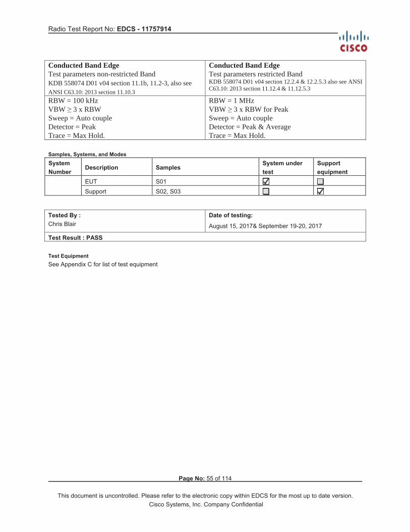
Conducted Band Edge Test parameters non-restricted Band KDB 558074 D01 v04 section 11.1b, 11.2-3, also see ANSI C63.10: 2013 section 11.10.3
Conducted Band Edge Test parameters restricted Band KDB 558074 D01 v04 section 12.2.4 & 12.2.5.3 also see ANSI C63.10: 2013 section 11.12.4 & 11.12.5.3
RBW = 100 kHz VBW 3 x RBW Sweep = Auto couple Detector = Peak Trace = Max Hold.
RBW = 1 MHz VBW 3 x RBW for Peak Sweep = Auto couple Detector = Peak & Average Trace = Max Hold.
Samples, Systems, and Modes System Number
Description Samples System under test
Support equipment
EUT S01 Support S02, S03
Tested By : Chris Blair
Date of testing:
August 15, 2017& September 19-20, 2017
Test Result : PASS Test Equipment See Appendix C for list of test equipment

Radio Test Report No: EDCS - 11757914
Page No: 56 of 114
This document is uncontrolled. Please refer to the electronic copy within EDCS for the most up to date version. Cisco Systems, Inc. Company Confidential
Conducted Band Edge (Non-Restricted Band 2390-2400MHz) - Peak
Cha
nnel
and
Ban
dEd
ge F
requ
ency
(M
Hz)
Mode Tx P
aths
Max
pow
er in
100
kHz
BW
(d
Bm
)
Pow
er in
100
kHz
BW
at
band
edg
e (d
Bm
)
Tota
l Atte
nuat
ion
(dB
)
Lim
it (d
B)
Mar
gIn
(dB
)
24022400 BLE (GFSK) 1 0.79 57.51 58.3 30 28.3
Conducted Band Edge - Peak
Cha
nnel
and
B
and
Edge
Fr
eque
ncy
(MH
z)
Mode Tx P
aths
Cor
rela
ted
Ant
enna
G
ain
(dB
i)
Tx 1
Ban
d Ed
ge L
evel
(d
Bm
)
Tota
l Ban
d Ed
ge
Leve
l (dB
m) =
Tx
1 Sp
ur p
ower
(dB
m) +
A
nten
na G
ain
(dB
i)
Lim
it (d
Bm
)
Mar
gIn
(dB
)
24022390 BLE (GFSK) 1 5.8 63.24 57.44 21.25 36.1924802483.5 BLE (GFSK) 1 5.8 54.45 48.65 21.25 27.4
Conducted Band Edge - Average
Cha
nnel
and
B
and
Edge
Fr
eque
ncy
(MH
z)
Mode Tx P
aths
Cor
rela
ted
Ant
enna
G
ain
(dB
i)
Tx 1
Ban
d Ed
ge L
evel
(d
Bm
)
Tota
l Ban
d Ed
ge
Leve
l (dB
m) =
Tx
1 Sp
ur p
ower
(dB
m) +
A
nten
na G
ain
(dB
i)
Lim
it (d
Bm
)
Mar
gIn
(dB
)
24022390 BLE (GFSK) 1 5.8 72.805 67.005 41.25 25.75524802483.5 BLE (GFSK) 1 5.8 64.795 57.44 41.25 16.19

Radio Test Report No: EDCS - 11757914
Page No: 57 of 114
This document is uncontrolled. Please refer to the electronic copy within EDCS for the most up to date version. Cisco Systems, Inc. Company Confidential
Conducted Band Edge, channel=2402 MHz, BLE (GFSK), Peak – Non-Restricted Band 2390-2400MHz

Radio Test Report No: EDCS - 11757914
Page No: 58 of 114
This document is uncontrolled. Please refer to the electronic copy within EDCS for the most up to date version. Cisco Systems, Inc. Company Confidential
Conducted Band Edge, channel=2402 MHz, BLE (GFSK), Average +2.05dB correction factor for duty cycle included in ref level offset. 5.8dBi antenna gain reflected in limit line: -41.25dBm – 5.8dBi = -47.05dBm.

Radio Test Report No: EDCS - 11757914
Page No: 59 of 114
This document is uncontrolled. Please refer to the electronic copy within EDCS for the most up to date version. Cisco Systems, Inc. Company Confidential
Conducted Band Edge, 2402 MHz, BLE (GFSK), Peak 5.8dBi antenna gain reflected in limit line: -41.25dBm – 5.8dBi = -47.05dBm.

Radio Test Report No: EDCS - 11757914
Page No: 60 of 114
This document is uncontrolled. Please refer to the electronic copy within EDCS for the most up to date version. Cisco Systems, Inc. Company Confidential
Conducted Band Edge, 2480 MHz, BLE (GFSK), Average +2.05dB correction factor for duty cycle included in ref level offset. 5.8dBi antenna gain reflected in limit line: -41.25dBm – 5.8dBi = -47.05dBm.

Radio Test Report No: EDCS - 11757914
Page No: 61 of 114
This document is uncontrolled. Please refer to the electronic copy within EDCS for the most up to date version. Cisco Systems, Inc. Company Confidential
Conducted Band Edge, 2480 MHz, BLE (GFSK), Peak 5.8dBi antenna gain reflected in limit line: -41.25dBm – 5.8dBi = -47.05dBm.

Radio Test Report No: EDCS - 11757914
Page No: 62 of 114
This document is uncontrolled. Please refer to the electronic copy within EDCS for the most up to date version. Cisco Systems, Inc. Company Confidential
Appendix B: Emission Test Results Testing Laboratory: Cisco Systems, Inc., 125 West Tasman Drive & 425 East Tasman Drive, San Jose, CA 95134, USA
B.1 Radiated Spurious Emissions 15.205 / RSS-Gen: Radiated emissions which fall in the restricted bands, as defined in Section
15.205(a) and RSS-Gen 8.10, must also comply with the radiated emission limits specified in Section 15.209(a) (see Section 15.205(c)) and RSS-Gen 8.9.
Ref. ANSI C63.10: 2013 section 4.1.4.2.2, 4.1.4.2.3, 6.6.4 & 11.12.2
Using Vasona, configure the spectrum analyzer as shown below (be sure to enter all losses between the transmitter output and the spectrum analyzer). Place the radio in continuous transmit mode.
Span: 1GHz – 18GHz / 18GHz – 26.5GHz Sweep Time: Coupled Resolution Bandwidth: 1MHz Video Bandwidth: 3 MHz for peak, 1 kHz for average Detector: Peak Terminate the access Point RF ports with 50 ohm loads.
Maximize Turntable (find worst case table angle), Maximize Antenna (find worst case height) Save 2 plots: 1) Average Plot (Vertical and Horizontal), Limit= 54dBuV/m @3m
2) Peak plot (Vertical and Horizontal), Limit = 74dBuV/m @3m Place a marker at the end of the restricted band closest to the transmit frequency to show compliance. Also measure any emissions in the restricted bands.
This report represents the worst case data for all supported operating modes and antennas. System Number Description Samples System under
test Support equipment
EUT S04 Support S03, S02
Tested By : Chris Blair
Date of testing:
August 18-25, 2017
Test Result : PASS See Appendix C for list of test equipment Note that duty cycle was increased to 87.5% for RSE. This duty cycle was not available at the time that conducted tests were done. See Appendix J for details.
Radio Test Report No: EDCS - 11757914
Page No: 63 of 114
This document is uncontrolled. Please refer to the electronic copy within EDCS for the most up to date version. Cisco Systems, Inc. Company Confidential
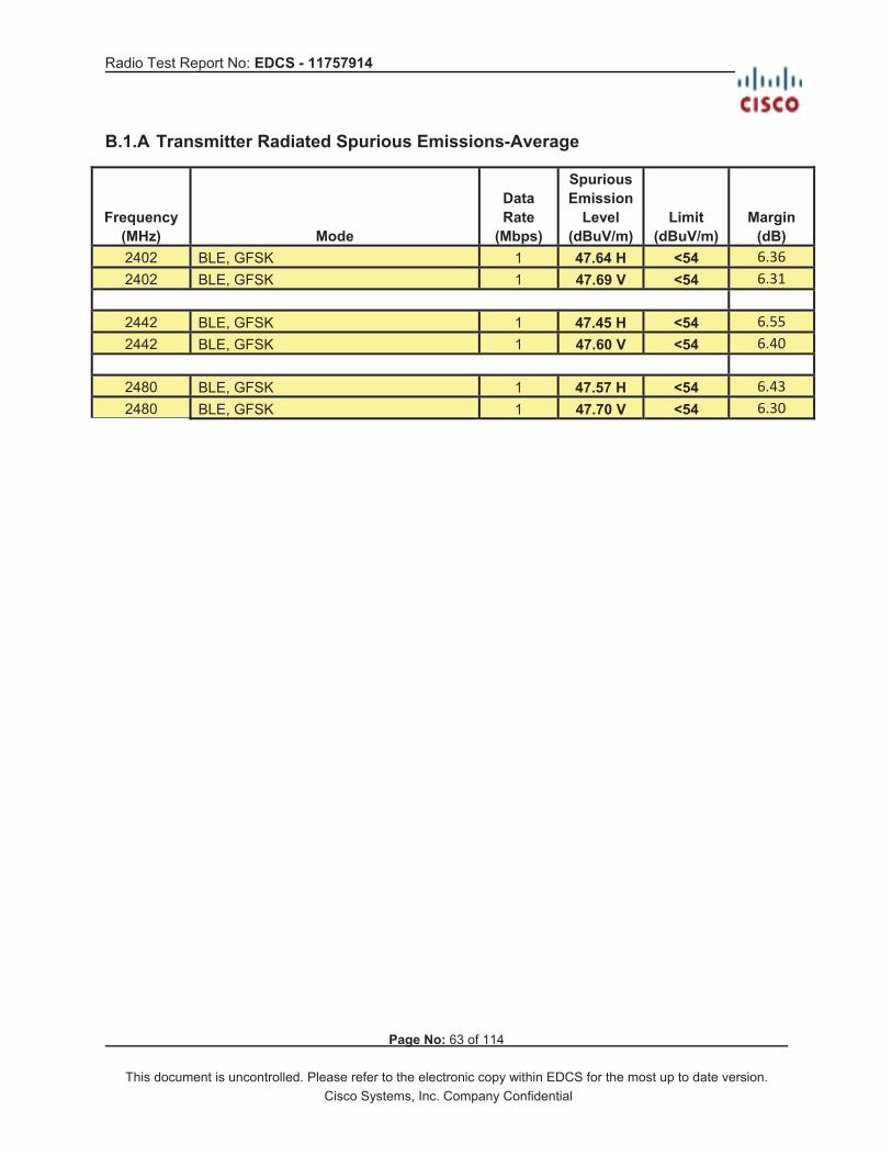
B.1.A Transmitter Radiated Spurious Emissions-Average
Frequency (MHz) Mode
Data Rate
(Mbps)
Spurious Emission
Level (dBuV/m)
Limit (dBuV/m)
Margin (dB)
2402 BLE, GFSK 1 47.64 H <54 6.36 2402 BLE, GFSK 1 47.69 V <54 6.31
2442 BLE, GFSK 1 47.45 H <54 6.55 2442 BLE, GFSK 1 47.60 V <54 6.40
2480 BLE, GFSK 1 47.57 H <54 6.43 2480 BLE, GFSK 1 47.70 V <54 6.30

Radio Test Report No: EDCS - 11757914
Page No: 64 of 114
This document is uncontrolled. Please refer to the electronic copy within EDCS for the most up to date version. Cisco Systems, Inc. Company Confidential
B.1.A.1 Radiated Transmitter Spurs, 2402 MHz, BLE (GFSK) , Average (1-18GHz), H
Radio Test Report No: EDCS - 11757914
Page No: 65 of 114
This document is uncontrolled. Please refer to the electronic copy within EDCS for the most up to date version. Cisco Systems, Inc. Company Confidential
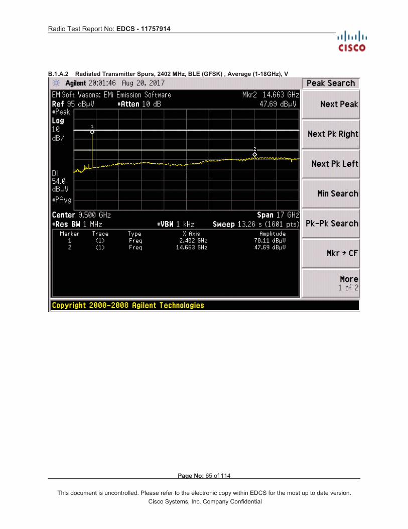
B.1.A.2 Radiated Transmitter Spurs, 2402 MHz, BLE (GFSK) , Average (1-18GHz), V

Radio Test Report No: EDCS - 11757914
Page No: 66 of 114
This document is uncontrolled. Please refer to the electronic copy within EDCS for the most up to date version. Cisco Systems, Inc. Company Confidential
B.1.A.3 Radiated Transmitter Spurs, 2442 MHz, BLE (GFSK) , Average (1-18GHz), H

Radio Test Report No: EDCS - 11757914
Page No: 67 of 114
This document is uncontrolled. Please refer to the electronic copy within EDCS for the most up to date version. Cisco Systems, Inc. Company Confidential
B.1.A.4 Radiated Transmitter Spurs, 2442 MHz, BLE (GFSK) , Average (1-18GHz), V

Radio Test Report No: EDCS - 11757914
Page No: 68 of 114
This document is uncontrolled. Please refer to the electronic copy within EDCS for the most up to date version. Cisco Systems, Inc. Company Confidential
B.1.A.5 Radiated Transmitter Spurs, 2480 MHz, BLE (GFSK) , Average (1-18GHz), H

Radio Test Report No: EDCS - 11757914
Page No: 69 of 114
This document is uncontrolled. Please refer to the electronic copy within EDCS for the most up to date version. Cisco Systems, Inc. Company Confidential
B.1.A.6 Radiated Transmitter Spurs, 2480 MHz, BLE (GFSK) , Average (1-18GHz), V

Radio Test Report No: EDCS - 11757914
Page No: 70 of 114
This document is uncontrolled. Please refer to the electronic copy within EDCS for the most up to date version. Cisco Systems, Inc. Company Confidential
B.1.A.7 Radiated Transmitter Spurs, All rate, All modes, Average (18-26.5GHz)
Radio Test Report No: EDCS - 11757914
Page No: 71 of 114
This document is uncontrolled. Please refer to the electronic copy within EDCS for the most up to date version. Cisco Systems, Inc. Company Confidential
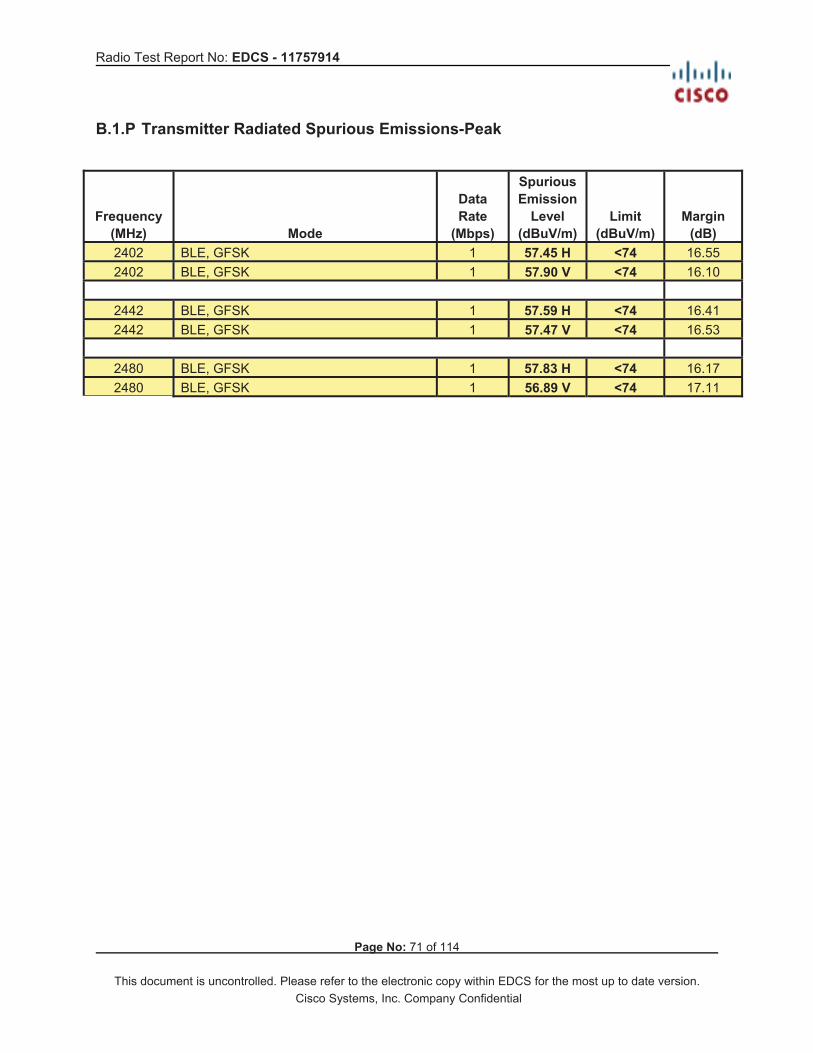
B.1.P Transmitter Radiated Spurious Emissions-Peak
Frequency (MHz) Mode
Data Rate
(Mbps)
Spurious Emission
Level (dBuV/m)
Limit (dBuV/m)
Margin (dB)
2402 BLE, GFSK 1 57.45 H <74 16.55 2402 BLE, GFSK 1 57.90 V <74 16.10
2442 BLE, GFSK 1 57.59 H <74 16.41 2442 BLE, GFSK 1 57.47 V <74 16.53
2480 BLE, GFSK 1 57.83 H <74 16.17 2480 BLE, GFSK 1 56.89 V <74 17.11

Radio Test Report No: EDCS - 11757914
Page No: 72 of 114
This document is uncontrolled. Please refer to the electronic copy within EDCS for the most up to date version. Cisco Systems, Inc. Company Confidential

Radio Test Report No: EDCS - 11757914
Page No: 73 of 114
This document is uncontrolled. Please refer to the electronic copy within EDCS for the most up to date version. Cisco Systems, Inc. Company Confidential
B.1.P.1 Radiated Transmitter Spurs, 2402 MHz, BLE (GFSK), Peak (1-18GHz), H

Radio Test Report No: EDCS - 11757914
Page No: 74 of 114
This document is uncontrolled. Please refer to the electronic copy within EDCS for the most up to date version. Cisco Systems, Inc. Company Confidential
B.1.P.2 Radiated Transmitter Spurs, 2402 MHz, BLE (GFSK), Peak (1-18GHz), V

Radio Test Report No: EDCS - 11757914
Page No: 75 of 114
This document is uncontrolled. Please refer to the electronic copy within EDCS for the most up to date version. Cisco Systems, Inc. Company Confidential
B.1.P.3 Radiated Transmitter Spurs, 2442 MHz, BLE (GFSK), Peak (1-18GHz), H

Radio Test Report No: EDCS - 11757914
Page No: 76 of 114
This document is uncontrolled. Please refer to the electronic copy within EDCS for the most up to date version. Cisco Systems, Inc. Company Confidential
B.1.P.4 Radiated Transmitter Spurs, 2442 MHz, BLE (GFSK), Peak (1-18GHz), V
Radio Test Report No: EDCS - 11757914
Page No: 77 of 114
This document is uncontrolled. Please refer to the electronic copy within EDCS for the most up to date version. Cisco Systems, Inc. Company Confidential
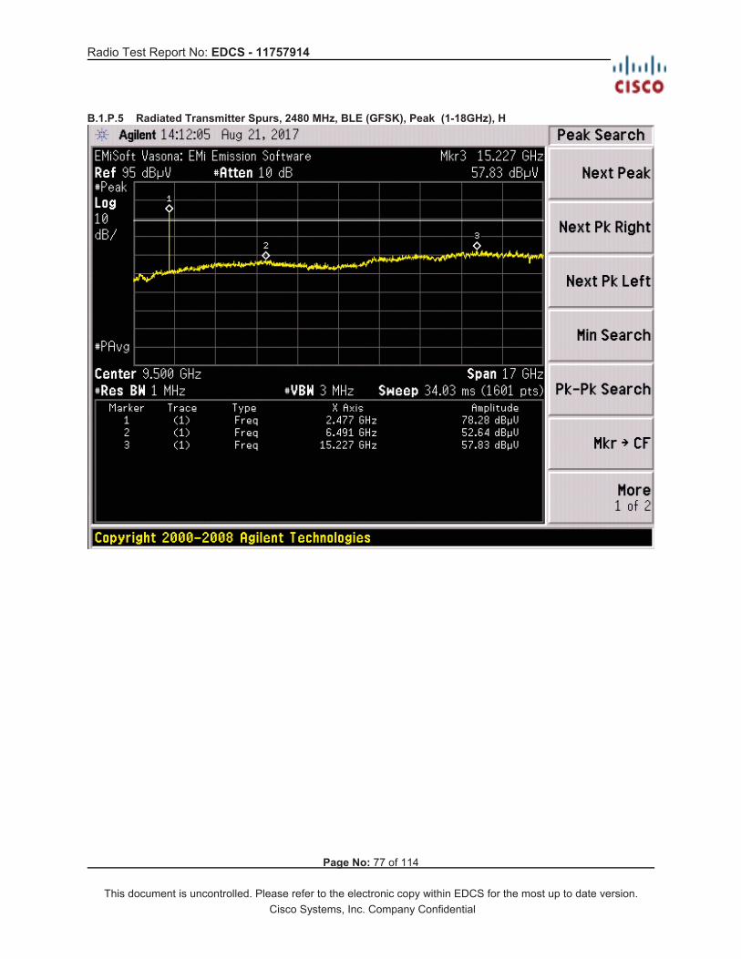
B.1.P.5 Radiated Transmitter Spurs, 2480 MHz, BLE (GFSK), Peak (1-18GHz), H

Radio Test Report No: EDCS - 11757914
Page No: 78 of 114
This document is uncontrolled. Please refer to the electronic copy within EDCS for the most up to date version. Cisco Systems, Inc. Company Confidential
B.1.P.6 Radiated Transmitter Spurs, 2480 MHz, BLE (GFSK), Peak (1-18GHz), V

Radio Test Report No: EDCS - 11757914
Page No: 79 of 114
This document is uncontrolled. Please refer to the electronic copy within EDCS for the most up to date version. Cisco Systems, Inc. Company Confidential
B.1.P.7 Radiated Transmitter Spurs, All rate, All modes, Peak (18-26.5GHz)

Radio Test Report No: EDCS - 11757914
Page No: 80 of 114
This document is uncontrolled. Please refer to the electronic copy within EDCS for the most up to date version. Cisco Systems, Inc. Company Confidential
B.2 Receiver Spurious Emissions RSS-GEN: Receivers are required to comply with the limits of spurious emissions as set out in this section. Receiver emission measurements are to be performed as per the normative test method referenced in section 3. Radiated emissions which fall in the restricted bands, as defined in RSS-Gen section 8.10, must also comply with the radiated emission limits specified in RSS-Gen section 8.9. For emissions at frequencies below 1 GHz, measurements shall be performed using a CISPR quasi-peak detector and the related measurement bandwidth. At frequencies above 1 GHz, measurements shall be performed using a linear average detector with a minimum resolution bandwidth of 1 MHz. Test Procedure Ref. RSS-GEN sec 8.9 & 8.10
ANSI C63.10: 2013 section 4.1.4.2.2, 4.1.4.2.3, 6.6.4 & 11.12.2 Using Vasona, configure the spectrum analyzer as shown below (be sure to enter all losses between the transmitter output and the spectrum analyzer). Place the radio in continuous Rx mode.
Span: 1GHz – 18GHz / 18GHz – 26.5GHz Sweep Time: Coupled Resolution Bandwidth: 1MHz Video Bandwidth: 3MHz for Peak, 1 kHz for average Detector: Peak Radiated emission measurements shall be performed with the receiver antenna connected to the receiver antenna terminals.
Maximize Turntable (find worst case table angle), Maximize Antenna (find worst case height) Save plot: 1) Average Plot (Vertical and Horizontal), Limit= 54dBuV/m @3m 2) Peak Plot (Vertical and Horizontal), Limit= 74dBuV/m @3m
This report represents the worst case data for all supported operating modes and antennas. System Number Description Samples System under
test Support equipment
EUT S04 Support S03, S02
Tested By : Chris Blair
Date of testing: August 18-25, 2017 Peak & Average Measurements
Test Result : PASS See Appendix C for list of test equipment

Radio Test Report No: EDCS - 11757914
Page No: 81 of 114
This document is uncontrolled. Please refer to the electronic copy within EDCS for the most up to date version. Cisco Systems, Inc. Company Confidential
B.2.A Receiver Radiated Spurious Emissions (Average Measurements)
B.2.A.1 Radiated Receiver Spurs, BLE (GFSK), Average (1-18GHz) Horizontal

Radio Test Report No: EDCS - 11757914
Page No: 82 of 114
This document is uncontrolled. Please refer to the electronic copy within EDCS for the most up to date version. Cisco Systems, Inc. Company Confidential
B.2.A.2 Radiated Receiver Spurs, BLE (GFSK), Average (1-18GHz), Vertical

Radio Test Report No: EDCS - 11757914
Page No: 83 of 114
This document is uncontrolled. Please refer to the electronic copy within EDCS for the most up to date version. Cisco Systems, Inc. Company Confidential
B.2.A.3 Radiated Receiver Spurs, BLE (GFSK), Average (18-26.5GHz), H+V

Radio Test Report No: EDCS - 11757914
Page No: 84 of 114
This document is uncontrolled. Please refer to the electronic copy within EDCS for the most up to date version. Cisco Systems, Inc. Company Confidential
B.2.P Receiver Radiated Spurious Emissions (Peak Measurements)
B.2.P.1 Radiated Receiver Spurs, BLE (GFSK), Peak (1-18GHz), Horizontal

Radio Test Report No: EDCS - 11757914
Page No: 85 of 114
This document is uncontrolled. Please refer to the electronic copy within EDCS for the most up to date version. Cisco Systems, Inc. Company Confidential
B.2.P.2 Radiated Receiver Spurs, BLE (GFSK), Peak (1-18GHz), Vertical

Radio Test Report No: EDCS - 11757914
Page No: 86 of 114
This document is uncontrolled. Please refer to the electronic copy within EDCS for the most up to date version. Cisco Systems, Inc. Company Confidential
B.2.P.3 Radiated Receiver Spurs, BLE (GFSK), Peak (18-26.5GHz)

Radio Test Report No: EDCS - 11757914
Page No: 87 of 114
This document is uncontrolled. Please refer to the electronic copy within EDCS for the most up to date version. Cisco Systems, Inc. Company Confidential
B.3 Radiated Emissions 30MHz to 1GHz 15.205 / 15.209 / RSS-Gen: Radiated emissions which fall in the restricted bands, as defined in Section 15.205(a) and RSS-GEN section 8.10, must also comply with the radiated emission limits specified in Section 15.209(a) (see Section 15.205(c)) and RSS-Gen section 8.9.
Test Procedure Ref. ANSI C63.10: 2013 section 6.5
Using Vasona, configure the spectrum analyzer as shown below (be sure to enter all losses between the transmitter output and the spectrum analyzer). Place the radio in continuous transmit mode.
Span: 30MHz – 1GHz Sweep Time: Coupled Resolution Bandwidth: 100kHz Video Bandwidth: 300kHz Detector: Peak for Pre-scan, Quasi-Peak
. Compliance shall be determined using CISPR quasi-peak detection; however, peak detection is permitted as an alternative to quasi-peak detection.
Terminate the access Point RF ports with 50 ohm loads.
Maximize Turntable (find worst case table angle), Maximize Antenna (find worst case height) This report represents the worst case data for all supported operating modes and antennas. System Number Description Samples System under
test Support equipment
EUT S04 Support S03, S02
Tested By : Chris Blair
Date of testing:
August 29, 2017
Test Result : PASS See Appendix C for list of test equipment

Radio Test Report No: EDCS - 11757914
Page No: 88 of 114
This document is uncontrolled. Please refer to the electronic copy within EDCS for the most up to date version. Cisco Systems, Inc. Company Confidential
Transmitter Radiated Emission
EMiSoft - Vasona Results
Test Radiated Emissions [Electric Field]
Class/Spec B / B RE FCC 30M-1GHz (3M)
Range 30 - 1000MHz
For cblair
Template RSE 15.209 30m-1GHz
Date/Time 29 Aug 17/14:52, Status: Filed on
Graphical Data
Formal Data
No Frequency
MHz
Raw
dBuV
Cable
Loss
AF dB Level
dBuV/m
Measure
Type
Pol Hgt
cm
Azt
Deg
Limit
dBuV/m
Margin
dB
Pass
/Fail
Comment
1 44.245 25.8 .7 10.8 37.3 Quasi Max V 106 169 40.0 -2.7 Pass hand/wide
2 212.891 26.7 1.4 10.5 38.6 Quasi Max H 128 347 43.5 -4.9 Pass hand
3 66.362 24.3 .8 7.9 33.0 Quasi Max V 113 260 40.0 -7.0 Pass hand
4 80.000 22.5 .9 7.4 30.7 Quasi Max V 144 314 40.0 -9.3 Pass hand
5 79.116 22.8 .8 7.5 31.1 Quasi Max V 125 348 40.0 -8.9 Pass hand/wide
Debug Data

Radio Test Report No: EDCS - 11757914
Page No: 89 of 114
This document is uncontrolled. Please refer to the electronic copy within EDCS for the most up to date version. Cisco Systems, Inc. Company Confidential
No Frequency
MHz
Raw
dBuV
Cable
Loss
AF dB Level
dBuV/m
Measure
Type
Pol Hgt
cm
Azt
Deg
Limit
dBuV/m
Margin
dB
Pass
/Fail
Comment
1 44.55 27.9 0.7 10.6 39.2 Peak [Scan] V 100 132 40 -0.8 Pass
2 213.087 26.6 1.4 10.5 38.5 Peak [Scan] H 100 352 43.5 -5 Pass
3 66.375 25.4 0.8 7.9 34.1 Peak [Scan] V 100 288 40 -5.9 Pass
4 79.106 25.3 0.8 7.5 33.7 Peak [Scan] V 100 325 40 -6.3 Pass
5 208.844 23.7 1.4 10.5 35.6 Peak [Scan] H 150 324 43.5 -7.9 Pass
6 848.438 11.7 2.8 22.1 36.5 Peak [Scan] H 100 291 46 -9.5 Pass

Radio Test Report No: EDCS - 11757914
Page No: 90 of 114
This document is uncontrolled. Please refer to the electronic copy within EDCS for the most up to date version. Cisco Systems, Inc. Company Confidential
Receiver Radiated Emission
EMiSoft - Vasona Results
est Radiated Emissions [Electric Field]
Class/Spec B / B RE FCC 30M-1GHz (3M)
Range 30 - 1000MHz
For cblair
Template RSE 15.209 30m-1GHz
Date/Time 29 Aug 17/16:09, Status: Filed on
Graphical Data
Formal Data
No Frequency
MHz
Raw
dBuV
Cable
Loss
AF dB Level
dBuV/m
Measureme
nt Type
Pol Hgt
cm
Azt
Deg
Limit
dBuV/m
Margin
dB
Pass
/Fail
Comment
1 44.244 25.1 .7 10.8 36.5 Quasi Max V 111 285 40.0 -3.5 Pass wide/hand
2 212.897 26.6 1.4 10.5 38.5 Quasi Max H 137 348 43.5 -5.0 Pass hand
3 66.363 23.8 .8 7.9 32.5 Quasi Max V 137 271 40.0 -7.5 Pass hand
4 78.844 22.3 .8 7.5 30.7 Quasi Max V 132 300 40.0 -9.3 Pass wide/hand
5 79.999 22.9 .9 7.4 31.1 Quasi Max V 108 314 40.0 -8.9 Pass wide/hand
Debug Data
No Frequency
MHz
Raw
dBuV
Cable
Loss
AF dB Level
dBuV/m
Measureme
nt Type
Pol Hgt
cm
Azt
Deg
Limit
dBuV/m
Margin
dB
Pass
/Fail
Comment

Radio Test Report No: EDCS - 11757914
Page No: 91 of 114
This document is uncontrolled. Please refer to the electronic copy within EDCS for the most up to date version. Cisco Systems, Inc. Company Confidential
1 43.944 27.7 0.7 11 39.4 Peak [Scan] V 100 201 40 -0.6 Pass
2 213.087 26.7 1.4 10.5 38.6 Peak [Scan] H 100 338 43.5 -4.9 Pass
3 66.375 26 0.8 7.9 34.7 Peak [Scan] V 100 252 40 -5.3 Pass
4 78.5 25.4 0.8 7.5 33.8 Peak [Scan] V 100 101 40 -6.2 Pass
5 208.844 23.6 1.4 10.5 35.4 Peak [Scan] H 150 323 43.5 -8.1 Pass

Radio Test Report No: EDCS - 11757914
Page No: 92 of 114
This document is uncontrolled. Please refer to the electronic copy within EDCS for the most up to date version. Cisco Systems, Inc. Company Confidential
B.4 AC Conducted Emissions
FCC 15.207 (a) & RSS-Gen 8.8 Except when the requirements applicable to a given device state otherwise, for any radio apparatus equipped to operate from the public utility AC power supply, either directly or indirectly (such as with a battery charger), the radio frequency voltage of emissions conducted back onto the AC power lines in the frequency range of 0.15 MHz to 30 MHz shall not exceed the limits shown in the table in these sections. The more stringent limit applies at the frequency range boundaries. Measurement Procedure Accordance with ANSI C63.10:2013 section 6.2
Using Vasona, configure the spectrum analyzer as shown below (be sure to enter all losses between the transmitter output and the spectrum analyzer). Place the radio in continuous transmit mode.
Span: 150 KHz – 30 MHz Sweep Time: Coupled Resolution Bandwidth: 9 KHz Video Bandwidth: 30 KHz Detector: Quasi-Peak / Average
System Number Description Samples System under
test Support equipment
EUT S05 Support S06, S07
Tested By : Chris Blair
Date of testing: 03 Oct 2017
Test Result : PASS
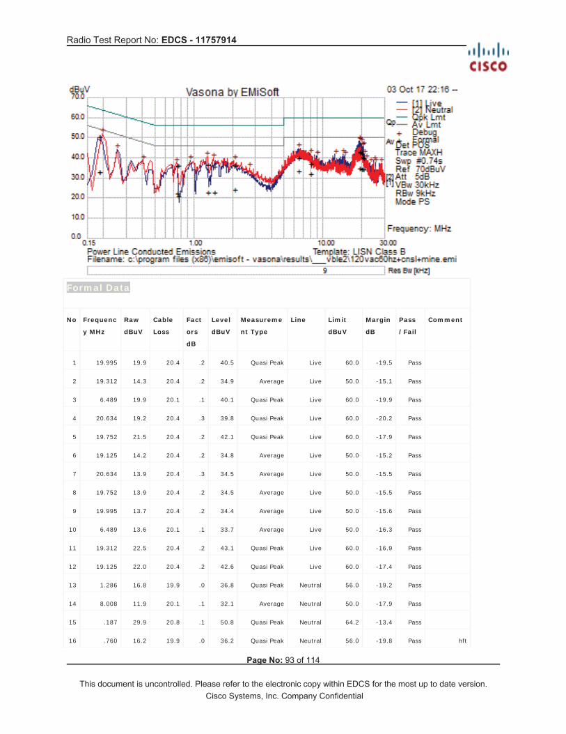
Radio Test Report No: EDCS - 11757914
Page No: 93 of 114
This document is uncontrolled. Please refer to the electronic copy within EDCS for the most up to date version. Cisco Systems, Inc. Company Confidential
Formal Data
No Frequenc
y MHz
Raw
dBuV
Cable
Loss
Fact
ors
dB
Level
dBuV
Measureme
nt Type
Line Limit
dBuV
Margin
dB
Pass
/Fail
Comment
1 19.995 19.9 20.4 .2 40.5 Quasi Peak Live 60.0 -19.5 Pass
2 19.312 14.3 20.4 .2 34.9 Average Live 50.0 -15.1 Pass
3 6.489 19.9 20.1 .1 40.1 Quasi Peak Live 60.0 -19.9 Pass
4 20.634 19.2 20.4 .3 39.8 Quasi Peak Live 60.0 -20.2 Pass
5 19.752 21.5 20.4 .2 42.1 Quasi Peak Live 60.0 -17.9 Pass
6 19.125 14.2 20.4 .2 34.8 Average Live 50.0 -15.2 Pass
7 20.634 13.9 20.4 .3 34.5 Average Live 50.0 -15.5 Pass
8 19.752 13.9 20.4 .2 34.5 Average Live 50.0 -15.5 Pass
9 19.995 13.7 20.4 .2 34.4 Average Live 50.0 -15.6 Pass
10 6.489 13.6 20.1 .1 33.7 Average Live 50.0 -16.3 Pass
11 19.312 22.5 20.4 .2 43.1 Quasi Peak Live 60.0 -16.9 Pass
12 19.125 22.0 20.4 .2 42.6 Quasi Peak Live 60.0 -17.4 Pass
13 1.286 16.8 19.9 .0 36.8 Quasi Peak Neutral 56.0 -19.2 Pass
14 8.008 11.9 20.1 .1 32.1 Average Neutral 50.0 -17.9 Pass
15 .187 29.9 20.8 .1 50.8 Quasi Peak Neutral 64.2 -13.4 Pass
16 .760 16.2 19.9 .0 36.2 Quasi Peak Neutral 56.0 -19.8 Pass hft

Radio Test Report No: EDCS - 11757914
Page No: 94 of 114
This document is uncontrolled. Please refer to the electronic copy within EDCS for the most up to date version. Cisco Systems, Inc. Company Confidential
17 1.428 16.0 19.9 .0 36.0 Quasi Peak Neutral 56.0 -20.0 Pass
18 .187 12.3 20.8 .1 33.2 Average Neutral 54.2 -21.0 Pass
19 .187 29.8 20.8 .1 50.7 Quasi Peak Neutral 64.2 -13.5 Pass hft
20 2.071 16.5 20.0 .1 36.5 Quasi Peak Neutral 56.0 -19.5 Pass
21 .747 16.1 19.9 .0 36.1 Quasi Peak Neutral 56.0 -19.9 Pass
22 .187 12.1 20.8 .1 33.0 Average Neutral 54.2 -21.2 Pass hft
23 2.071 4.1 20.0 .1 24.1 Average Neutral 46.0 -21.9 Pass
24 8.008 17.0 20.1 .1 37.2 Quasi Peak Neutral 60.0 -22.8 Pass
25 1.428 3.0 19.9 .0 23.0 Average Neutral 46.0 -23.0 Pass
26 1.286 2.9 19.9 .0 22.9 Average Neutral 46.0 -23.2 Pass
27 .747 2.5 19.9 .0 22.5 Average Neutral 46.0 -23.5 Pass
28 .760 .9 19.9 .0 20.9 Average Neutral 46.0 -25.1 Pass hft
No Frequenc
y MHz
Raw
dBuV
Cable
Loss
Fact
ors
dB
Level
dBuV
Measureme
nt Type
Line Limit
dBuV
Margin
dB
Pass
/Fail
Comment
1 19.299 27.8 20.4 .2 48.4 Peak [Scan] Live 50.0 -1.6 Pass
2 .195 31.3 20.8 .1 52.1 Peak [Scan] Neutral 53.8 -1.7 Pass
3 19.135 27.6 20.4 .2 48.2 Peak [Scan] Live 50.0 -1.8 Pass
4 19.747 27.0 20.4 .2 47.6 Peak [Scan] Live 50.0 -2.4 Pass
5 20.642 25.1 20.4 .3 45.8 Peak [Scan] Live 50.0 -4.2 Pass
6 19.985 24.8 20.4 .2 45.4 Peak [Scan] Live 50.0 -4.6 Pass
7 6.493 24.7 20.1 .1 44.8 Peak [Scan] Live 50.0 -5.2 Pass
8 1.269 20.7 19.9 .0 40.6 Peak [Scan] Neutral 46.0 -5.4 Pass
9 1.419 19.8 19.9 .0 39.8 Peak [Scan] Neutral 46.0 -6.2 Pass
10 .254 23.8 20.5 .0 44.4 Peak [Scan] Live 51.6 -7.2 Pass
11 2.060 18.7 20.0 .0 38.7 Peak [Scan] Neutral 46.0 -7.3 Pass
12 .941 18.7 19.9 .0 38.6 Peak [Scan] Live 46.0 -7.4 Pass
13 14.224 21.6 20.3 .2 42.0 Peak [Scan] Live 50.0 -8.0 Pass
14 8.001 21.7 20.1 .1 41.9 Peak [Scan] Neutral 50.0 -8.1 Pass
15 20.926 21.2 20.4 .3 41.8 Peak [Scan] Live 50.0 -8.2 Pass
16 12.403 21.5 20.2 .1 41.8 Peak [Scan] Live 50.0 -8.2 Pass
Radio Test Report No: EDCS - 11757914
Page No: 95 of 114
This document is uncontrolled. Please refer to the electronic copy within EDCS for the most up to date version. Cisco Systems, Inc. Company Confidential
17 .732 17.6 19.9 .0 37.6 Peak [Scan] Neutral 46.0 -8.4 Pass
18 14.732 20.8 20.3 .2 41.2 Peak [Scan] Live 50.0 -8.8 Pass
19 .404 18.9 20.0 .0 39.0 Peak [Scan] Neutral 47.8 -8.8 Pass
20 9.045 20.7 20.1 .1 40.9 Peak [Scan] Live 50.0 -9.1 Pass
21 21.687 18.5 20.4 .3 39.1 Peak [Scan] Live 50.0 -10.9 Pass
22 2.687 15.1 20.0 .0 35.1 Peak [Scan] Neutral 46.0 -10.9 Pass
23 24.896 17.7 20.5 .3 38.5 Peak [Scan] Live 50.0 -11.5 Pass
24 23.194 16.8 20.4 .3 37.5 Peak [Scan] Live 50.0 -12.5 Pass
25 25.448 16.7 20.5 .3 37.5 Peak [Scan] Live 50.0 -12.5 Pass
26 28.119 16.3 20.5 .4 37.3 Peak [Scan] Neutral 50.0 -12.7 Pass

Radio Test Report No: EDCS - 11757914
Page No: 96 of 114
This document is uncontrolled. Please refer to the electronic copy within EDCS for the most up to date version. Cisco Systems, Inc. Company Confidential
Appendix C: List of Test Equipment Used to perform the test
Equip# Manufacturer/ Model Description Last Cal Next Due Test Item
Test Equipment used for Radiated Emissions (Radio)
32544 ETS Lindgren 3117 Double Ridged Horn Antenna
12 Jul 2017
12 Jul 2018
54393 Huber+Suhner Sucoflex 102 RF Cable 2.4mm - N Type 18GHz
27 Apr 2017
27 Apr 2018
54398 Huber+Suhner Sucoflex 102 RF Cable 2.4mm - N Type 18GHz
27 Apr 2017
27 Apr 2018
56053 Miteq TTA1800-30-HG
SMA 18GHz Pre Amplifier
08 Mar 2017
08 Mar 2018
55178 Huber+Suhner Sucoflex 106PA
RF Type N Antenna Cable 18 GHz 8.5m
02 Dec 2016
02 Dec 2017
25640 Micro-coax UFB311A-0-2720-520520
Coaxial Cable, 272.0 in. to 18GHz
02 Dec 2016
02 Dec 2017
25660 Micro-coax UFB311A-1-0840-504504
Coaxial Cable, 84.0 in. to 18GHz
02 Dec 2016
02 Dec 2017
40604 Keysight 4440A Spectrum Analyzer 3Hz-26.5GHz
11 Nov 2016
11 Nov 2017
51688 Dynawave 5400-9810-6251
SMA 50 Ohm Termination 18GHz
29 Jun 2017
29 Jun 2018
53964 Newport iBTHP-5-DB9
5 inch Temp/RH/Press Sensor w/20ft cable
09 Feb 2017
09 Feb 2018
33041 Fluke 175 True RMS DMM 01 Jun 2017
01 Jun 2018
35237 Stanley 33-696
TAPE RULE 5M NA NA
35233 Stanley 33-696
TAPE RULE 5M NA NA
34072 SCHAFFNER RSG 2000
Reference Spectrum Generator, 1-18GHz NA NA
37557 JFW 50HF-010N
Attenuator 02 Feb 2017
02 Feb 2018
4226 Emco 3115 Horn Antenna NA NA
20490 Keysight 8710-1765
PRESET TORQUE WRENCH, 8lb-in
06 Feb 2017
06 Feb 2018
8113 Cisco NSA 5m Chamber
NSA 5m Chamber
31 Aug 2016
31 Aug 2017
43024 Cisco Above 1GHz Site Cal
1GHz Cispr Site Verification
03 Oct 2016
03 Oct 2017
34740 ETS Lindgren 3117 Double Ridged Horn Antenna
19 Oct 2016
19 Oct 2017

Radio Test Report No: EDCS - 11757914
Page No: 97 of 114
This document is uncontrolled. Please refer to the electronic copy within EDCS for the most up to date version. Cisco Systems, Inc. Company Confidential
39126 Cisco TH0118
Mast Mount Preamplifier Array, 1-18GHz
02 May 2017
02 May 2018
39131 Cisco TH0118-PS
Power Supply for TH0118 1-18GHz Preamplifier
NA NA
37234 JFW 50CB-015
Control Box, GPIB
NA NA
38404 Sunol Sciences JB1 Combination Antenna, 30MHz-2GHz
05 Oct 2016
05 Oct 2017
5732 York CNE V COMPARISON NOISE EMITTER
NA NA
55589 Keysight 5173B EXG-B MW ANALOG SIGNAL GENERATOR
07 Jul 2017
07 Jul 2018
18231 Rhode & Schwarz ESI 40 RECEIVER TEST 20Hz-40GHz
03 Feb 2017
03 Feb 2018
36710 Cisco 1840 18-40GHz EMI Test Head/Verification Fixture
17 Nov 2016
17 Nov 2017
Test Equipment used for AC Mains Conducted Emissions (EMC)
04003 Fischer Custom Communications FCC-801-M2-32A
CDN, 2-LINE, 32A 2017-03-16 2018-03-16
005466 Keithley580 Micro-Ohmmeter 2016-10-31 2017-10-31 056329 Pasternack PE5019-1 Torque Wrench 2017-03-01 2018-03-01
041933 Newport iBTHP-5-DB9 5 inch Temp/RH/Press Sensor w/20ft cable
2016-12-22 2017-12-22
045991 Fischer Custom Communications F-090527-1009-2
Lisn Adapter 2017-06-15 2018-06-15
049468 Coleman RG223 BNC 25 ft Cable 2017-03-10 2018-03-10 008357 Coleman RG-223 1.5 ft RG-223 Cable 2017-04-12 2018-04-12 046715 Bird5-T-MB 5W 50 Ohm BNC Termination 4GHz 2017-03-16 2018-03-16 008496 FCC-450B-2.4-N Instrumentation Limiter 2017-05-16 2018-05-16 033041 Fluke175 Multimeter 2017-06-01 2018-06-01
018963 York CNE V Comparison Noise Emitter, 30 - 1000MHz
NA NA
045050 Rohde & Schwarz ESCI EMI Test Receiver 2016-11-09 2017-11-09
045990 Fischer Custom Communications F-090527-1009-1
Line Impedance Stabilization Network 2017-06-15 2018-06-15
007448 Fischer Custom Communications F-201-32mm
Absorbing Clamp NA NA
046714 Bird5-T-MB 5W 50 Ohm BNC Termination 4GHz 2016-11-28 2017-11-28 049531 TTE H785-150K-50-21378 High Pass Filter 2017-05-03 2018-05-03 054647 Stanley33-605 10meter Measuring Tape NA NA
Test Equipment Used for RF Conducted Tests

Radio Test Report No: EDCS - 11757914
Page No: 98 of 114
This document is uncontrolled. Please refer to the electronic copy within EDCS for the most up to date version. Cisco Systems, Inc. Company Confidential
55980 Keysight N9020A-508
MXA Signal Analyzer, 10Hz-8.4GHz
11 Oct 2016
11 Oct 2017
51799 Huber+Suhner Sucoflex101PE
40 GHz Cable, K-Type
16 Nov 2016
16 Nov 2017
51802 Huber+Suhner Sucoflex101PE
40 GHz Cable, K-Type
16 Nov 2016
16 Nov 2017
6335 Lufft 5063-33W
Dial Hygrometer 16 Aug 2017
16 Aug 2018
20490 Keysight 8710-1765
PRESET TORQUE WRENCH, 8lb-in
06 Feb 2017
06 Feb 2018
33041 Fluke 175 True RMS DMM 01 Jun 2017
01 Jun 2018
55191 York EMC Series CGE03C
Comb Generator NA NA
49516 Keysight N9030A-550
PXA Signal Analyzer, 3Hz to 50GHz
02 Nov 2016
02 Nov 2017
6324 Lufft 5063-33W
Dial Hygrometer 02 Nov 2016
02 Nov 2017
54058 Aeroflex 40AH2W-20
SMA Attenuator, 20 dB 40GHz
21 Apr 2017
21 Apr 2018

Radio Test Report No: EDCS - 11757914
Page No: 99 of 114
This document is uncontrolled. Please refer to the electronic copy within EDCS for the most up to date version. Cisco Systems, Inc. Company Confidential
Appendix D: Abbreviation Key and Definitions The following table defines abbreviations used within this test report. Abbreviation Description Abbreviation Description
EMC Electro Magnetic Compatibility F Degrees Fahrenheit EMI Electro Magnetic Interference C Degrees Celsius EUT Equipment Under Test Temp Temperature ITE Information Technology Equipment S/N Serial Number TAP Test Assessment Schedule Qty Quantity ESD Electro Static Discharge emf Electromotive force EFT Electric Fast Transient RMS Root mean square EDCS Engineering Document Control
System Qp Quasi Peak
Config Configuration Av Average CIS# Cisco Number (unique identification
number for Cisco test equipment) Pk Peak
Cal Calibration kHz Kilohertz (1x10³) EN European Norm MHz MegaHertz (1x10⁶) IEC International Electro technical
Commission GHz Gigahertz (1x10⁹)
CISPR International Special Committee on Radio Interference
H Horizontal
CDN Coupling/Decoupling Network V Vertical LISN Line Impedance Stabilization
Network dB decibel
PE Protective Earth V Volt GND Ground kV Kilovolt (1x10³) L1 Line 1 V Microvolt (1x10⁻⁶) L2 Line2 A Amp L3 Line 3 A Micro Amp (1x10⁻⁶) DC Direct Current mS Milli Second (1x10⁻³) RAW Uncorrected measurement value,
as indicated by the measuring device
S Micro Second (1x10⁻⁶)
RF Radio Frequency S Micro Second (1x10⁻⁶) SLCE Signal Line Conducted Emissions m Meter Meas dist Measurement distance Spec dist Specification distance N/A or NA Not Applicable SL Signal Line (or Telecom Line) P Power Line L Live Line N Neutral Line R Return S Supply AC Alternating Current

Radio Test Report No: EDCS - 11757914
Page No: 100 of 114
This document is uncontrolled. Please refer to the electronic copy within EDCS for the most up to date version. Cisco Systems, Inc. Company Confidential
Appendix E: Photographs of Test Setups

Radio Test Report No: EDCS - 11757914
Page No: 112 of 114
This document is uncontrolled. Please refer to the electronic copy within EDCS for the most up to date version. Cisco Systems, Inc. Company Confidential
Appendix G: Test Procedures
Measurements were made in accordance with KDB 558074 - D01 DTS Meas Guidance v04 KDB 662911 - MIMO ANSI C63.4 2014 Unintentional Radiators ANSI C63.10 2013 Intentional Radiators
Test procedures are summarized below FCC 2.4GHz Test Procedures EDCS # 1445042 FCC 2.4GHz RSE Test Procedures EDCS # 1480386

Radio Test Report No: EDCS - 11757914
Page No: 113 of 114
This document is uncontrolled. Please refer to the electronic copy within EDCS for the most up to date version. Cisco Systems, Inc. Company Confidential
Appendix H: Scope of Accreditation (A2LA certificate number 1178-01) The scope of accreditation of Cisco Systems, Inc. can be found on the A2LA web page at: http://www.a2la.org/scopepdf/1178-01.pdf

Radio Test Report No: EDCS - 11757914
Page No: 114 of 114
This document is uncontrolled. Please refer to the electronic copy within EDCS for the most up to date version. Cisco Systems, Inc. Company Confidential
Appendix I: Test Assessment Plan Compliance Test Plan (Excel) EDCS# 11670323 Target Power Tables: NA. UUT only has 1 power setting
Appendix J: Worst Case Justification The UUT is BLE, and only has 1 mode (BLE, GFSK), and 1 power setting for all domains. The power is set in radio firmware, and is not accessible to the user. The duty cycle was 62.4% for conducted measurements, but was increased to 87.5% for RSE. At the time of conducted tests, 62.4% was the only duty cycle that was available to the test engineer (0x25 HCI). A correction factor (+2.05dB) corresponding to the actual duty cycle (62.4%) was used in calculations for conducted tests. Radiated tests were performed subsequently, and 87.5% duty cycle was the highest available (0x7D HCI), and was used for those tests. Although 2 duty cycles were used, [1] RSE testing was done at the highest duty cycle available, and [2] conducted tests were compensated by duty cycle correction factor. Both of these scenarios exceed the expected use of the transmitter, as the UUT is intended to receive 90-95% of the time.