Radio Signal Analyzer - OVH · Radio Signal Analyzer (RSA) is a user-friendly software to analyse...
25
1 Note: Only the last version of this document available on the sigfox technical system documentation is official and applicable. This document is confidential and is the property of Sigfox. It shall not be copied and / or disclosed to third parties, in any form without SIGFOX written permission.” Radio Signal Analyzer User guide March 2018
Transcript of Radio Signal Analyzer - OVH · Radio Signal Analyzer (RSA) is a user-friendly software to analyse...
1
Note: Only the last version of this document available on the sigfox technical system documentation is official and applicable. This document is confidential and is the property of Sigfox. It shall not be copied and / or disclosed to third parties, in any form without SIGFOX written permission.”
Radio Signal Analyzer User guide
March 2018

2
Contents
1. GENERAL INFORMATION ............................................................................................................ 3
1.1 SYSTEM OVERVIEW ....................................................................................................................... 3 1.2 TESTING EQUIPMENT ..................................................................................................................... 3 1.3 TECHNICAL CHARACTERISTICS ....................................................................................................... 3
2. REQUIREMENTS ........................................................................................................................... 4
2.1 HARDWARE .................................................................................................................................. 4 2.2 SOFTWARE ................................................................................................................................... 4 2.3 DEVICE......................................................................................................................................... 5
3. OS INTERFACE ............................................................................................................................. 6
4. APPLICATION INTERFACE .......................................................................................................... 7
4.1 TESTER SELECTION ....................................................................................................................... 8 4.2 DEVICE CONFIGURATION ............................................................................................................... 8 4.3 DEVICE RF INPUT ......................................................................................................................... 9 4.4 MAIN TABS .................................................................................................................................... 9 4.5 SETUP INFORMATION ................................................................................................................... 10
5. RF MEASUREMENT WINDOW ................................................................................................... 11
6. INFO /…/ VERDICTS WINDOW ................................................................................................... 12
6.1 INFORMATION, PREREQUISITES AND EQUIPMENT .......................................................................... 12 6.2 VERDICTS ................................................................................................................................... 13
7. SIGFOX VERIFIED™ TESTS ...................................................................................................... 14
7.1 TX-BPSK (TEST MODE 0) .......................................................................................................... 14 7.2 TX-PROTOCOL (TEST MODE 1) ................................................................................................ 15 7.3 RX-PROTOCOL (TEST MODE 2) ............................................................................................... 16 7.4 RX-GFSK (TEST MODE 3) .......................................................................................................... 17 7.5 RX-SENSITIVITY (TEST MODE 4) ............................................................................................. 17 7.6 TX-SYNTH (TEST MODE 5) ........................................................................................................ 18
8. EXPORT RESULTS ..................................................................................................................... 19
ANNEX: USB BOOT GUIDE ................................................................................................................ 21
PREREQUISITES................................................................................................................................... 21 ISO CREATION .................................................................................................................................... 21 USB BOOT .......................................................................................................................................... 22 SETTING PREFERENCES (KEYBOARD AND TIME) ..................................................................................... 24 CUTECOM ........................................................................................................................................... 25

3
1. General information
1.1 System overview Radio Signal Analyzer (RSA) is a user-friendly software to analyse Sigfox’ signals. It can decode frames and analyse a device RF signal (Modulation, Demodulation, Ultra Narrow Band Spectrum shaping occupation, Datarate accuracy, Phase accuracy, Frequency dynamic drift …). This software compares the results with the Sigfox Verified™ requirements as a summary and allows to make a pre-certification of the device. The detailed Sigfox Verified test procedures are available for each Radio Configuration on https://build.sigfox.com/sigfox-verified-certification
1.2 Testing equipment Radio Signal Analyzer can be used with various testing equipment. Some options and test results will differ depending on the equipment used. As the main available equipment is the Sigfox SDR Dongle, it is the one used in this guide. Radio Signal Analyzer, run with the SDR Dongle, is intended to be only used for pre-certification tests and do not replace any certification tests in test houses or Sigfox labs. Some tests will not provide conclusive results. The Sigfox SDR dongle is designed for use connected to a computer, in a laboratory and not a manufacturing environment. SDR dongle is not calibrated in frequency and RF level. It must not be used to calibrate your device in frequency and RF level. It must not be used for manufacturing/production tests. It must not be used to calibrate your RSSI level in device RX mode Using the dongle without attenuator could result in permanent damage to the equipment. If these recommendations are not followed, there is no warranty on the validity of the results.
1.3 Technical characteristics All tests for Sigfox Verified™ certification must be executed in conducted mode. There is no warranty on the test results if RF measurements are executed in radiated mode. For more information on the Sigfox SDR dongle technical characteristics please refer to the datasheet (https://resources.sigfox.com/document/sigfox-sdr-dongle).
4
2. Requirements
2.1 Hardware For running Radio Signal Analyser, it is required to use a computer with:
• 64-bit compatible processor
• 2 GB RAM minimum
• USB boot capability
• USB 2.0 High Speed port (for SDR Dongle)
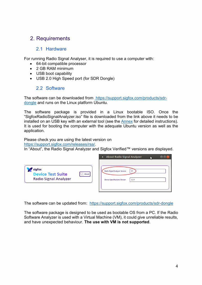
2.2 Software The software can be downloaded from https://support.sigfox.com/products/sdr-dongle and runs on the Linux platform Ubuntu. The software package is provided in a Linux bootable ISO. Once the “SigfoxRadioSignalAnalyzer.iso” file is downloaded from the link above it needs to be installed on an USB key with an external tool (see the Annex for detailed instructions). It is used for booting the computer with the adequate Ubuntu version as well as the application.
Please check you are using the latest version on https://support.sigfox.com/releases/rsa/. In “About”, the Radio Signal Analyzer and Sigfox Verified™ versions are displayed.
The software can be updated from: https://support.sigfox.com/products/sdr-dongle The software package is designed to be used as bootable OS from a PC. If the Radio Software Analyzer is used with a Virtual Machine (VM), it could give unreliable results, and have unexpected behaviour. The use with VM is not supported.

5
2.3 Device The device under development must have a SMA or U.FL connector to be used in conducted mode. The person running the tests must be able to activate the test modes from the device library. To demodulate the signal, the device ID field should be populated In case of a device with operational ID, you need to set up the private key with the default key: 00112233445566778899AABBCCDDEEFF.

6
3. OS interface After the USB boot up connect the SDR dongle to the computer.
On the desktop, there are pre-set shortcuts to:
• Radio Signal Analyzer application
• CuteCom terminal (for AT commands, see the Annex)
• Useful web pages (latest version of this user guide, the test procedures and RC specifications).
• An extra shortcut can appear for external USB storage device. By default, the keyboard is set to English “qwerty”, in order to change it, please refer to the Annex. When the computer goes to “sleep’” mode, if the session gets locked or suspended, the system will request a password to resume the session. The password is “rsa”. Note: make sure you have the right language setting for you keyboard.
7
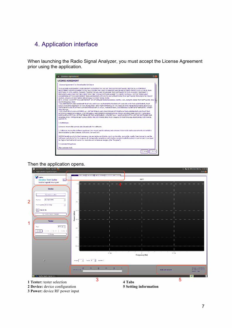
4. Application interface When launching the Radio Signal Analyzer, you must accept the License Agreement prior using the application.
Then the application opens. 2
1 1 Tester: tester selection
2 Device: device configuration
3 Power: device RF power input
4 Tabs
5 Setting information
4
5 3
8
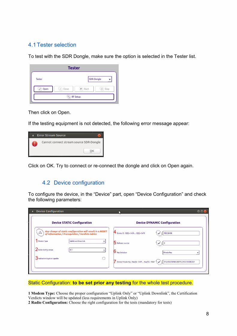
4.1 Tester selection To test with the SDR Dongle, make sure the option is selected in the Tester list.
Then click on Open. If the testing equipment is not detected, the following error message appear:
Click on OK. Try to connect or re-connect the dongle and click on Open again.
4.2 Device configuration To configure the device, in the “Device” part, open “Device Configuration” and check the following parameters:
Static Configuration: to be set prior any testing for the whole test procedure. 1 Modem Type: Choose the proper configuration “Uplink Only” or “Uplink Downlink”, the Certification
Verdicts window will be updated (less requirements in Uplink Only)
2 Radio Configuration: Choose the right configuration for the tests (mandatory for tests)
2
3
1
4
5
6
7

9
3 Payload encryption capable: yes or no
Dynamic Configuration: can be set in-between tests according to the test procedure. 4 Device ID: Write the device ID number (remove any default value. If less than 8 characters, add 0 before)
5 Rollover counter: Used with payload encryption
6 Key Selection: Choose public or private key (if known)
7 Device Private Key Default value: Test Private Key
The configuration is saved as soon as selected or filled, hence any change in the static configuration will reset the test results. The red dot beside Device Configuration means that there is an error in the dynamic configuration.
4.3 Device RF input Evaluate the device’s power emissions.
To be in the best condition, the Band Power should be between -40 and -15 dBFS (dB relative to full scale) when the device is emitting.
RF power input should be adjusted to guaranty maximum reliability on RF measurements.
4.4 Main tabs
FFT (Fast Fourier Transform): display signal on all sigfox band
Demodulation: display all frames recorded by the equipment from the given device ID.

10
RF Measurement: displays all RF analysis Frequency Distribution: display the frequency distribution of the device under test Info/Prereq/Equipment/Verdicts: contains information and verdicts required for the report
Note: The tabs Information, Prerequisite and Equipment should be documented prior running the tests.
4.5 Setup information
The information is displayed on the bottom right corner of the screen.
Radio switched to RX: RSA is listening to the device. Radio switched to TX: RSA is emitting to the device. The UL Frequency, DL Frequency and Datarate are the corresponding values for selected Radio Configuration.

11
5. RF Measurement Window All RF Measurement are done with the same Test Mode (mentioned in the Test Procedure). If more than 3 frames are sent, the worst value stays in memory for the final verdict.
The green line shows Sigfox’ spectrum limit.

12
6. Info /…/ Verdicts Window Sigfox SDR dongle cannot target all verdicts (sensitivity, listen before talk feature, calibration etc..) so external setup is needed to take the remaining tests before submitting to Verified Certification.
6.1 Information, Prerequisites and Equipment The information required on these three tabs should be filled out prior running the tests and must be completed before exporting the results.
Prerequisites must include the steps and commands used (see the Be prepared for Sigfox Verified™ Certification document).
If you have different test setups, you can save them and load them as needed.
13
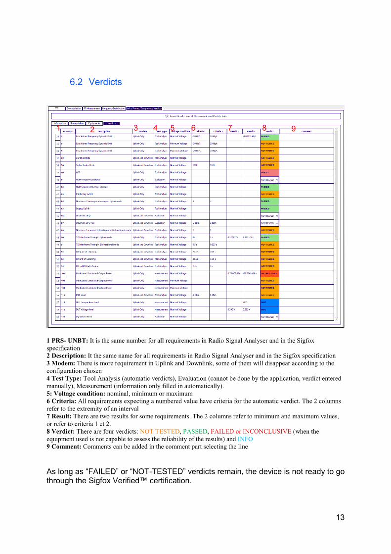
6.2 Verdicts
1 PRS- UNBT: It is the same number for all requirements in Radio Signal Analyser and in the Sigfox
specification
2 Description: It the same name for all requirements in Radio Signal Analyser and in the Sigfox specification
3 Modem: There is more requirement in Uplink and Downlink, some of them will disappear according to the
configuration chosen
4 Test Type: Tool Analysis (automatic verdicts), Evaluation (cannot be done by the application, verdict entered
manually), Measurement (information only filled in automatically).
5: Voltage condition: nominal, minimum or maximum
6 Criteria: All requirements expecting a numbered value have criteria for the automatic verdict. The 2 columns
refer to the extremity of an interval
7 Result: There are two results for some requirements. The 2 columns refer to minimum and maximum values,
or refer to criteria 1 et 2.
8 Verdict: There are four verdicts: NOT TESTED, PASSED, FAILED or INCONCLUSIVE (when the
equipment used is not capable to assess the reliability of the results) and INFO
9 Comment: Comments can be added in the comment part selecting the line
As long as “FAILED” or “NOT-TESTED” verdicts remain, the device is not ready to go through the Sigfox Verified™ certification.
1 2 3 4 5 6 7 8 9
14
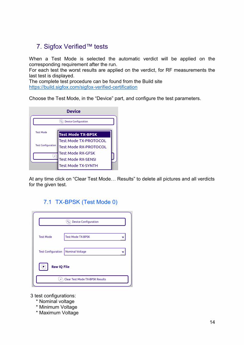
7. Sigfox Verified™ tests When a Test Mode is selected the automatic verdict will be applied on the corresponding requirement after the run. For each test the worst results are applied on the verdict, for RF measurements the last test is displayed. The complete test procedure can be found from the Build site https://build.sigfox.com/sigfox-verified-certification Choose the Test Mode, in the “Device” part, and configure the test parameters.
At any time click on “Clear Test Mode… Results” to delete all pictures and all verdicts for the given test.
7.1 TX-BPSK (Test Mode 0)
3 test configurations: * Nominal voltage * Minimum Voltage * Maximum Voltage

15
The Test TX-BPSK must be run for all 3 voltages. Test coverage: Spectrum measurement, Datarate measurement, Dynamic Drift measurement, Phase measurement, Envelope measurement, Static Drift measurement, Power measurement Explanation: The RF Measurement part of the certification is done on several frames at a fixed frequency (For example, in RC1 it is 868.13 MHz). From these transmissions, RSA will be able to make a verdict on all UPLINK RF parameters. If one of those transmissions is out of specification, the associated verdict will be marked as failed. You can see the results in the “RF Measurement” tab and the verdicts in "Info / Prereq / Equipment / Verdicts" -> "Verdicts". This test mode does not require to have a specific ID, but if not recognised, the modulation column will display “wrong ID”
7.2 TX-PROTOCOL (Test Mode 1)
2 test configurations: * Protocol * Frequency Distribution Test coverage: Uplink Protocol, Timings, Frequency Distribution Explanation: The uplink protocol must be tested on all types of frames (Data and OOB) for all the possible payload lengths (Bit, 1 - 12 Bytes) the Sigfox library could generate. It also checks the frequency distribution in the Sigfox band to see if it is homogeneous or not. This test mode should be run with the actual Device ID and its private key, but can be run in public key if not available. The demodulated frames are displayed in the "Demodulation" tab and the frequency distribution in the "Frequency Distribution" tab. You can also see the verdicts in the tab "Info / Prereq / Equipment / Verdicts" -> "Verdicts"

16
7.3 RX-PROTOCOL (Test Mode 2)
3 test configurations: * Standard * Start of listening * End of listening Test coverage: Downlink Protocol, Timings, GFSK Response Listening Window Explanation: The downlink protocol is validated on reception of the OOB frame. In the Standard mode, the timer is set to the middle of the listening window. In the Start of listening, the timer is set to the shortest possible timing value for a GFSK response configured in a Sigfox base station. In the End of listening, the timer is set to the longest possible timing value for a GFSK response configured in a Sigfox base station. You can see the verdicts in the tab "Info / Prereq / Equipment / Verdicts" -> "Verdicts"

17
7.4 RX-GFSK (Test Mode 3)
Test coverage: GFSK demodulation. Explanation: The RX-GFSK mode does not use the library to decode a GFSK response, it expects a constant pattern which is the same size as a Sigfox GFSK response. In this mode, the application will send periodically this constant pattern to the device, the device stays in listening mode until the GFSK stops. Manually fill the verdicts in the tab "Info / Prereq / Equipment / Verdicts" -> "Verdicts".
7.5 RX-SENSITIVITY (Test Mode 4)
Test coverage: Device Link Budget with Sigfox Protocol Explanation: The RX-SENSITIVITY test mode is working as the standard downlink protocol with changed feature (1 frame sent, 1 frame received) to accelerate the test.

18
In this mode, the program will build and send response to the device at a controlled output level to evaluate the link budget. (not valid with SDR-Dongle, it can only test the behaviour, not the sensitivity). Visualize the demodulated frames in the "Demodulation" tab. You can also see the verdicts in the tab "Info / Prereq / Equipment / Verdicts" -> "Verdicts".
7.6 TX-SYNTH (Test Mode 5)
Test coverage: Device Frequency Step Explanation: The TX-SYNTH test mode is used to characterize the capability for a device to generate a define frequency. It will ensure that the device can use a maximum of the Sigfox Band. Visualize the demodulated frames in the "Demodulation" tab. You can also see the verdicts in the tab "Info / Prereq / Equipment / Verdicts" -> "Verdicts".

19
8. Export Results The Radio Signal Analyser software will generate a package containing: * Graph plots * IQ Wave * Product picture * Information / Prerequisites / Equipment / Verdicts It is important to fill the Information / Prerequisites / Equipment tabs to generate a full VALID report (Not-tested or empty comment in these tables are considered as failed). You will find in the destination folder a SigfoxVerifiedCertification.tar.gz archive containing the full package. Do not edit or modify this folder in any way. From this package, Sigfox can generate the PDF report for the certification.
Click on “Export results” from the Verdicts tab. You must select an empty destination folder or create a new one to save your results. You can export directly on an external drive (NOT the bootable USB key currently used). Warning: the process will delete all content of the destination folder before exporting Steps to export the full package: 1) Select the folder where the files will be sent to and click open:
Once you have clicked “Open”, you won’t be able to cancel the export process.

20
2) You can select a picture of the device (size limited to 4MB, in .png format) to add to the export files or skip this step:
3) You can add the I/Q recording (in .raw format) to the export files:
4) If the files were saved locally, copy them on an external or online storage for later access.

21
Annex: USB boot guide
Prerequisites
• The latest .iso file downloaded on the computer
• a 2 GB USB key
• a tool to format the file on a bootable USB key. (here UNetbootin)
ISO creation
Download UNetbootin at this address: http://unetbootin.github.io/ according to the computer OS.
It is a simple prebuilt program it won’t be installed on the computer, just run it.
Select “Diskimage” – “ISO” – path to /SigfoxRadioSignalAnalyzer.iso
You can add persistent memory to save your settings during your sessions (300 MB in this example)
Select “Type” USB Drive” and the mounted drive that was enumerated in the OS (here F:\).
22
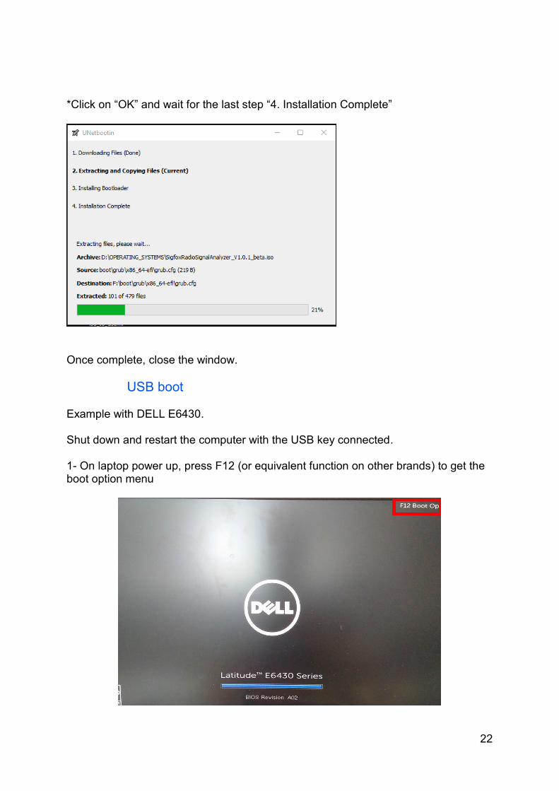
*Click on “OK” and wait for the last step “4. Installation Complete”
Once complete, close the window.
USB boot Example with DELL E6430. Shut down and restart the computer with the USB key connected. 1- On laptop power up, press F12 (or equivalent function on other brands) to get the boot option menu

23
2- Then select the USB device to boot (take care if you’re in secure boot, it could create some issues).
Depending on the application used to create the booting USB you may get another screen, select “Try without installing”.

24
Setting preferences (keyboard and time) By default, the keyboard of the ISO is set to QWERTY, to change it, go to: System -> Preferences -> Hardware -> Keyboard Click on the Layouts tab to add relevant keyboard languages.
The time zone is set for GMT. To change to a different time zone, go to: System -> Administration -> Time and Date
To unlock the access, the password is the same as the user name.

25
CuteCom Example of the CuteCom terminal: