Balun-klinikka · Balun-klinikka OH2AP, OH2Z, OH2AA, OH2K 2013 Matti Hohtola OH7SV
Radio FUNdamentals THINGS TO LEARN, PROJECTS TO BUILD, AND GEAR TO USE
The Coax Balun
H a v e you read the great series of CQ articles on ferrite baluns written by Jerry Sevick, W2FMI? If not, better get out your back copies of this magazine and go over this important and interesting information.
Jerry mentions air-core coax baluns in passing, but the main theme of his work deals with ferrite-core devices. However, there is a place in the world for the air-core design, and I'd like to discuss here two interesting, inexpensive baluns of this type.
An advantage of the ferrite-core balun is it has a greater frequency range and is usually more compact than its air-core counterpart. And conversely, the air-core balun is larger and more bulky than the ferrite equivalent, especially if the former is wound with coax as the conductor.
The air-core coax balun, on the other hand, can be made cheaply and is not subject to core saturation, which can cause a number of unpleasant things to happen. The balun core can saturate and overheat with accompanying power loss, causing an increase in harmonic generation and intermodulation.
It is interesting and easy to build an air-core balun, and here are some coax types with which you can experiment and draw your own conclusions as to their utility.
The 1-to-1 Coax Balun
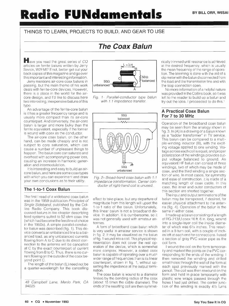
The first I read of a wideband coax balun was in the 1959 publication Principles of Single Sideband, published by the Collins Radio Company. This book discussed baluns in the chapter describing feed systems suited to 52 ohm coax line (which had become the feedline of choice in the 1950s). A simple parallel-conductor balun was described (fig. 1). This device converts an unbalanced line to a balanced load, as any unbalanced currents flowing from A to C due to its direct connection to the antenna will be cancelled at C by the exact counterpart of current flowing from B to C. Thus, there is no current flowing on the outside of the coax beyond point C.
The length of the balun (L) need not be a quarter-wavelength for the cancelling
48 Campbell Lane, Menlo Park, CA 94025
j" J B
A
Fig. 1- Parallel-conductor type balun with 1:1 impedance transfer.
Fig. 2- Broad-band coax balun with 1:1 impedance transformation. Center con
ductor of right-hand coil is unused.
effect to take place, but any departure of magnitude from this length will upset the 1-to-1 ratio of the balun. Unfortunately, this linear balun is not a broadband device. In addition, it is cumbersome, so it was not generally used with amateur antennas.
A form of broadband coax balun which is very useful in amateur service is shown in fig. 2. It may be visualized as the balun of fig. 1 wound into a coil. This physical representation does not cover the real operation of the device, which is somewhat more complex. However, a coiled coax balun is capable of operating over a much wider range of frequencies than is its linear counterpart, shown in fig. 1, without upsetting the impedance at the output termination.
The coax balun is wound to a diameter limited by the bending radius of the coax (about 15 times the cable diameter). The ends of the resulting coil are then symmet
rically trimmed until resonance is achieved at the desired frequency, which is usually the mean frequency of the range of operation. The trimming is done with the aid of a dip meter with the balun disconnected from the load and the transmission line and with the loop connection open.
No more information of a helpful nature was provided in the Collins book, so it was left to the reader to build up a balun and try out the idea. I proceeded to do this.1
A Practical Coax Balun For 7 to 30 MHz
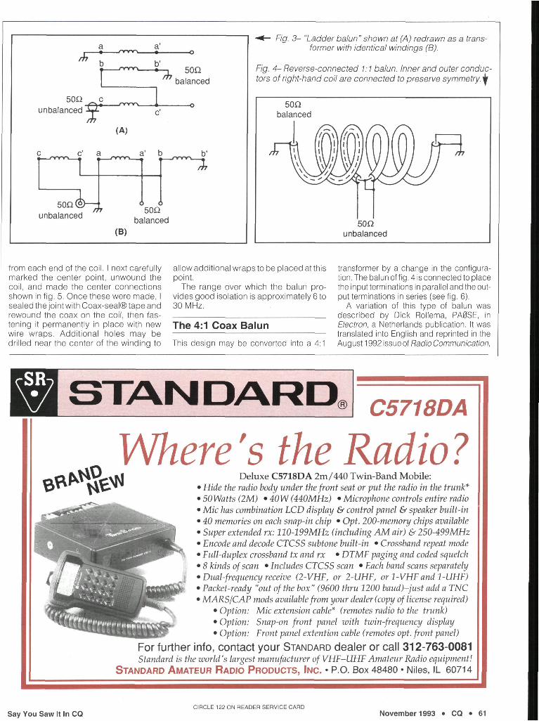
Operation of the broadband coax balun may be seen from the analogy shown in fig. 3. In (A) is a drawing of a balun known as a "ladder transformer" in TV service. This balun can be compared to a multiple-winding inductor (B), with the exciting voltage applied to one winding. Voltage across each coil is equal, and proper polarization of the windings provides output voltage balanced to ground. An equivalent HF balun can consist of three windings, two of which may be made of coax, and the third winding a single section of wire. In most cases, for symmetry and ease of construction, it is made of a matching length of coax cable. In this case, the inner and outer conductors of this section are shorted together.
The input and outputterminations of the balun may be transposed, if desired, for easier physical attachment to the antenna (fig. 4). Operation of the balun is the same in either case.
I made up a balun consisting of a length of RG-213/U coax 16 ft. 6 in. long, wound into a single-layer coil the inside diameter of which was 63/4 inches. This resulted in a 9-turn coil, with a couple of inches left at each end for connections. I used a section of gray PVC water pipe as the coil form.
I wound the coil on the form temporarily and marked the points on the PVC corresponding to the ends of the winding. I then removed the winding and drilled small holes through the wall of the form at each spot previously marked with the pencil. The coil was then rewound on the form and held in place temporarily with plastic wire wraps passed through the holes I had just drilled. The center junction of the winding is exactly 41/2 turns
60 • CQ • November 1993 Say You Saw It In CQ
JT
50Q unbalanced r u — m n n _ . c a
50Q(°> unbalanced m
(A)
a'
b b'
tmzr ^7 50fi
balanced
a' b
6 6 50Q
balanced
•^— F/'gr. 3- "Ladder balun" shown at (A) redrawn as a transformer with identical windings (B).
Fig. 4- Reverse-connected 1:1 balun. Inner and outer conductors of right-hand coil are connected to preserve symmetry, jf
(B)
50Q balanced
50Q unbalanced
from each end of the coil. I next carefully allow additional wraps to be placed at this marked the center point, unwound the coil, and made the center connections shown in fig. 5. Once these were made, I sealed the joint with Coax-seal® tape and rewound the coax on the coil, then fastening it permanently in place with new wire wraps. Additional holes may be drilled near the center of the winding to
point. The range over which the balun pro
vides good isolation is approximately 6 to 30 MHz.
The 4:1 Coax Balun
This design may be converted into a 4:1
transformer by a change in the configuration. The balun of fig. 4 is connected to place the input terminations in parallel and the output terminations in series (see fig. 6).
A variation of this type of balun was described by Dick Rollema, PA0SE, in Electron, a Netherlands publication. It was translated into English and reprinted in the August 1992 issue of Radio Communication,
STANDARD. C5718DA
Where's the Radio ? Deluxe C5718DA 2m/440 Twin-Band Mobile:
• Hide the radio body under the front seat or put the radio in the trunk* • 50Watts (2M) • 40W (440MHz) • Microphone controls entire radio • Mic has combination LCD display & control panel & speaker built-in • 40 memories on each snap-in chip • Opt. 200-memory chips available • Super extended rx: 110-199MHz (including AM air) & 250-499MHz • Encode and decode CTCSS subtone built-in • Crossband repeat mode • Full-duplex crossband tx and rx • DTMF paging and coded squelch • 8 kinds of scan • Includes CTCSS scan • Each band scans separately • Dual-frequency receive (2-VHF, or 2-UHF, or 1-VHF and 1-UHF) • Packet-ready "out of the box" (9600 thru 1200 baud)-just add a TNC • MARS/CAP mods available from your dealer (copy of license required)
• Option: Mic extension cable* (remotes radio to the trunk) • Option: Snap-on front panel with twin-frequency display • Option: Front panel extention cable (remotes opt. front panel)
For further info, contact your STANDARD dealer or call 312-763-0081 Standard is the world's largest manufacturer of VHF-UHF Amateur Radio equipment!
STANDARD AMATEUR RADIO PRODUCTS, INC. • P.O. Box 48480 • Niles, IL 60714
CIRCLE 122 ON READER SERVICE CARD
Say You Saw It In CQ November 1993 • CQ • 61
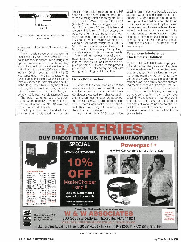
Fig. 5- Close-up of center connection of the balun.
a publication of the Radio Society of Great Britain.
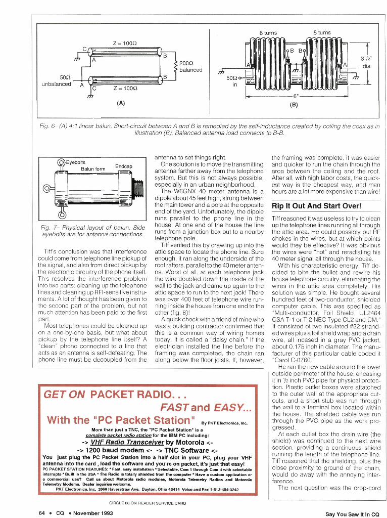
The 4:1 design uses small-diameter 75 ohm coax (RG-59/U, or equivalent). This particular coax is chosen, even though the optimum impedance value for the winding should be about half the value of the terminating load—in this case 200 ohms. Not having any 100 ohm coax at hand, the RG-59 was substituted. The balun consists of 16 turns, split at the center, wound on a PVC form 31/2 inches in diameter and about 6 inches long. Instead of making the balun of a single, tapped length of coax, two separate pieces were used, making in effect, two adjacent coils, each with eight turns of coax.
The balun windings are cross-connected at the ends (A to A and C to C). I used short pieces of No. 12 stranded hookup wire to do the job.
I built up a balun and it worked okay, but I felt that I could obtain a more con
stant transformation ratio across the HF bands if I used a higher impedance coax for the winding. After snooping around, I found that The Wiremanz listed RG-62A/U (95 ohm) coax in their catalog (stock number 141). I ordered 20 feet of this line and rewound the balun. As I expected, the balance and transformation ratio was much better than that achieved in the RG-59/U configuration, the new winding providing an operating range of 3.5 to 30 MHz. Performance dropped off above 29 MHz, but I think this was probably due to my relatively long interconnecting leads.
The maximum power level of the 4:1 balun is unknown. The RG- 62A/U coax is rather fragile stuff, so I limited the applied power to 150 watts. At this power it performed in a satisfactory manner with no sign of heating or deterioration.
Balun Construction
The ends of the coax windings are the weak points of the coax baluns. The outer conductor must be tinned, and the inner conductor protected from physical strain. After the terminating leads are attached, the coax ends must be protected from the weather with Coax-seal®, or the equivalent. Balun mounting will depend upon the individual installation.
I found that black ABS plastic pipe
used for drain lines was equally as good as the PVC pipe and easier to cut and handle. ABS end caps can be obtained and epoxied in position when the balun is complete. An outline of my low-power balun, designed for use with an off-center fed, multiband antenna is shown in fig. 7. I didn't epoxy the end caps on; rather I fastened them to the coil form by means of sheet-metal screws. In that way I could dismantle the balun if I wished to make any changes.
Telephone Interference The Ultimate Solution
My friend Tiff, W6GNX, has been plagued off and on over the years with bad telephone interference. Once he discovered that an unused phone sitting in the corner of the room picked up his 40 meter signal even when it was disconnected from the line! And the telephone answering machine was a puzzlement. Interference on it varied, depending on where it was placed in the house, and moving some telephones from room to room created different levels of interference in them. Line filters, such as described in my past columns, helped some phones, but there were other phones, Tiff found, that even the best line filter could not completely help.
BUY DIRECT FROM US, THE MANUFACTURER!
YAESU/MAXON FNB-2 10.8v @ 600 MAH FNB-3/3A 9.6v @ 1200 MAH FNB-4 12v © 750 MAH FNB-4A 12v @ 1000 MAH
*FNB-10(S) 7.2v@ 1150 MAH FNB-12(S) 12vO 600 MAH equiv. to FNB-11 (%" shorter) FNB-17 7.2V 8 600 MAH
"Same size case as FNB-12 •FNB-25 7.2v ® 600 MAH FNB-26 7.2V @ 1000 MAH
"FNB-26-S 7.2v ® 1500 MAH TNB-26A 9.6V @ 800 MAH *Same size as FNB-26 case FNB27 12v @ 600 MAH
"FNB-27S 12v m 800 MAH "{%" longer than FNB27)
€& NYS residents add 8 1/4% sales tax. Add $4.00 for postage and handling.
SPECIAL FOR THE
MONTH OF NOVEMBER
10% OFF
MasterCharger I and I I '
Look for December's special of the month
Monthly discounts applicable to end-users only
Powerpac+® 6 V for Camcorders & 12 V for 2-way
Prices and Specifications sub|ect to change without notice
800 South Broadway, Hicksville, N.Y. 11801
MADE IN THE U.S.A.
SEND FOR FREE CATALOG
In U.S. & Canada Call Toll Free (800) 221-0732 • In NYS (516) 942-0011 • FAX (516) 942-1944
CIRCLE 131 ON READER SERVICE CARD
62 • CQ • November 1993 Say You Saw It In CQ
50Q unbalanced A
z = ioon
;200Q • balanced
8 turns
(B)
8 turns
p t 3V2" riia
1=L-&
A, |
Fig. 6- (A) 4:1 linear balun. Short-circuit between A and B is remedied by the self-inductance created by coiling the coax as in illustration (B). Balanced antenna load connects to B-B.
@=
(o) [ Eyebolts Balun form
—
ndcap
1 Fig. 7- Physical layout of balun. Side eyebolts are for antenna connections.
Tiff's conclusion was that interference could come from telephone line pickup of the signal, and also from direct pickup by the electronic circuitry of the phone itself. This resolves the interference problem into two parts: cleaning up the telephone lines and cleaning up RFI-sensitive instruments. A lot of thought has been given to the second part of the problem, but not much attention has been paid to the first part.
Most telephones could be cleaned up on a one-by-one basis, but what about pickup by the telephone line itself? A "clean" phone connected to a line that acts as an antenna is self-defeating. The phone line must be decoupled from the
antenna to set things right. One solution is to move the transmitting
antenna farther away from the telephone system. But this is not always possible, especially in an urban neighborhood.
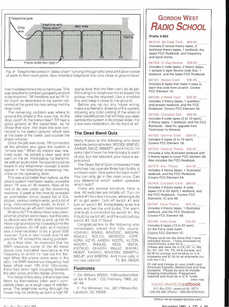
The W6GNX 40 meter antenna is a dipole about 45 feet high, strung between the main tower and a pole at the opposite end of the yard. Unfortunately, the dipole runs parallel to the phone line in the house. At one end of the house the line runs from a junction box out to a nearby telephone pole.
Tiff verified this by crawling up into the attic space to locate the phone line. Sure enough, it ran along the underside of the roof rafters, parallel to the 40 meter antenna. Worst of all, at each telephone jack the wire doubled down the inside of the wall to the jack and came up again to the attic space to run to the next jack! There was over 400 feet of telephone wire running inside the house from one end to the other (fig. 8)!
A quick check with a friend of mine who was a building contractor confirmed that this is a common way of wiring homes today. It is called a "daisy chain." If the electrician installed the line before the framing was completed, the chain ran along below the floor joists. If, however,
GET ON PACKET RADIO... FAST and EASY...
With the "PC Packet Station" By PKT Electronics, Inc.
More than just a TNC, the "PC Packet Station" is a complete packet radio station for the IBM PC including:
-> VHF Radio Transceiver by Motorola <--> 1200 baud modem <• -> TNC Software <-
You just plug the PC Packet Station into a half slot in your PC, plug your VHF antenna into the card , load the software and you're on packet, it's just that easy! PC PACKET STATION FEATURES: • Fast, easy installation * Selectable, Com 1 through Com 4 with selectable interrupts * Built in the USA * The Radio is totally shielded from the computer * Have a custom application or a commercial use? Call us about Motorola radio modules, Motorola Telemetry Radios and Motorola Telemetry Modems. Dealer inquiries welcome.
PKT Electronics, Inc. 2668 Haverstraw Ave. Dayton, Ohio 45414 Voice and Fax 1 -513-454-0242
CIRCLE 86 ON READER SERVICE CARD
64 • CQ • November 1993
the framing was complete, it was easier and quicker to run the chain through the area between the ceiling and the roof. After all, with high labor costs, the quickest way is the cheapest way, and man hours are a lot more expensive than wire!
Rip It Out And Start Over!
Tiff reasoned it was useless to try to clean up the telephone lines running all through the attic area. He could possibly put RF chokes in the wires, but at which points would they be effective? It was obvious the wires were "hot" and reradiating his 40 meter signal all through the house.
With his characteristic energy, Tiff decided to bite the bullet and rewire his house telephone circuitry, eliminating the wires in the attic area completely. His solution was simple. He bought several hundred feet of two-conductor, shielded computer cable. This was specified as "Multi-conductor, Foil Shield, UL2464 CSA T-1 or T-2 NEC Type CL2 and CM." It consisted of two insulated #22 stranded wires plus a foil shield wrap and a drain wire, all incased in a gray PVC jacket, about 0.175 inch in diameter. The manufacturer of this particular cable coded it "Carol C-0760."
He ran the new cable around the lower outside perimeter of the house, encasing it in 1/2 inch PVC pipe for physical protection. Plastic outlet boxes were attatched to the outer wall at the appropriate cutouts, and a short stub was run through the wall to a terminal box located within the house. The shielded cable was run through the PVC pipe as the work progressed.
At each outlet box the drain wire (the shield) was continued to the next wire section, providing a continuous shield running the length of the telephone line. Tiff reasoned that the shielding, plus the close proximity to ground of the chain, would do away with the annoying interference.
The next question was the drop-cord
Say You Saw It In CQ
' Telephone pole
Attic area
Phone outlet box (typ)
Fig. 8- Telephones wired in "daisy chain" running through attic area and down inside of walls to floor-level jacks. New shielded telephone line runs close to ground level.
from the telephone pole to the house. This was telephone company property and not to be touched. Tiff therefore put an RF filter (such as described in my earlier columns) at the point his new wiring met the drop cord.
The remaining problem was where to ground the shield of the coax line. At the drop cord? At the transmitter? Tiff had a good ground at the transmitter, so he chose that spot. The drain line was connected to the station ground, which was at the base of his tower, just outside the shack window.
Once the job was done, Tiff connected all the phones and gave the system a "smoke test." When 40 meters was relatively quiet, he picked a clear spot and went on the air, modulating his transmitter with an audio tone. No sound could be heard in any telephone—except a weak signal in the telephone answering machine on his operating desk.
This was a lot better than before, as the phone system had been nearly unusable when Tiff was on 40 meters. Now all he had to do was clean up the answering machine. A peek at the innards revealed an unshielded circuit board full of ICs, diodes, various components, and a lot of long, interconnecting leads. In brief, it functioned as an efficient radio receiver!
What to do? The daisy chain was clean, all other phones were clean, but this pesky device was still able to pick up his 40 meter signal and pump it (weakly) into the phone system. As Tiff said, all it needed was a beat-oscillator to be a good SSB receiver! Tune in next month and I'll tell you how Tiff solved this vexing problem.
As a final note, he observed that the SWR response curve of the 40 meter dipole now indicated resonance at the frequency to which he had cut the flattop! When the phone wires were in the attic, the SWR resonance frequency had been offset over 100 kHz! Obviously, there had been tight coupling between the attic wires and the dipole antenna.
The moral of this story is that telephone filters by themselves often won't completely clean up a tough case of interference. The telephone wiring through the house may be picking up such a high RF
signal level that the filter can't do its job. Rerouting the telephone line to lessen the pickup may be required. Use a shielded line and keep it close to the ground.
Before you rip out any house wiring, make a schematic drawing of the system, showing any color coding of the wires or other identification that will help you reassemble the system in its proper order. For a two-wire installation, its not hard at all!
The Dead Band Quiz
Many thanks to the following who have sent me personal notes: W20QI , W9PVD, AA4GR, N4UZ, WB8SFT, and K1KLO. I'm sorry I don't have the time to reply to each of you, but rest assured, your input is appreciated.
The Dead Band Quiz concerned three switches that operate three light bulbs in a closed room. One switch for each bulb? You can only go in the room once. Can you determine which switch operates which bulb?
There are several solutions. Here is one. All switches are initially off. Turn on switch #1 for a few minutes, allowing bulb #1 to get warm. Turn off switch #1 and turn on switch #2. Immediately enter the room and feel the unlit bulbs. The warm unlit bulb is controlled by switch # 1 , the lit bulb by switch #2, and the cold bulb by switch #3. Got it? Good.
Congratulations to the following who immediately solved this little puzzle: KD4VAU, W5IKB, WN2SQC, W6GPM, WA5JCI, W2LCV, WD9DDO, K2PF, K5RA, KZ1R, AA9DH, W2ZPL, KL7DN, W4GRY, W4GJG, AE5E, W60K, KB7WJQ, KE4ARH, W6JJZ, W4EHU, NH6ZF, KA3VVC, WA2DWV, WB6BYU, N8SJP, and WB6IYM. And more calls in my next column! 73, Bill, W6SAI
Footnotes 1. Orr, William, W6SAI, "A Broadband Bal-un for A Buck," CQ, February 1966, pp. 42-44.
2. The Wireman, Inc., 261 Pittman Rd., Landrum, SC 29356.
GORDON WEST
RADIO SCHOOL Prefix 0-823
08731X No Code Tech. $49.95 Includes 2 novice theory tapes, 2 technical theory tapes, 1 textbook, the latest FCC Rulebook, and frequency and band charts.
087328 21-Day Novice $39.95 Includes 2 code tapes, 2 theory tapes, 1 sample 5 wpm Novice code test, 1 textbook, and the latest FCC Rulebook.
087301 Novice Code $39.95 Includes 6 tapes that make it easy to learn the code from scratch. Covers FCC Element 1A.
087336 2-Week Tech. $34.95 Includes 2 theory tapes, 1 question-and-answer textbook, and the FCC Rulebook. Covers FCC Element 3A.
087360 Complete Gen. $69.95 Includes 6 code tapes (5 to 13 wpm), 2 theory tapes, 1 textbook, and the FCC Rulebook. Ideal for upgrade from Technician to General.
087352 General Code $39.95 Includes 6 tapes (5 to 13 wpm). Covers FCC Element 1B.
087344 General Theory $34.95 Includes a fully illustrated textbook with 2 theory tapes to cover FCC element 3B. Also includes the FCC Rulebook.
087379 Adv. Theory $44.95 Includes 4 theory tapes, 1 illustrated textbook, and the FCC Rulebook. Covers FCC Element 4A.
087409 Complete Extra $69.95 Includes 4 theory tapes, 6 code tapes (13 to 22 wpm) 1 textbook, and the FCC Rulebook. Covers FCC Elements 1C and 4B.
087387 Extra Theory $44.95 Includes 4 theory tapes, 1 illustrated textbook, and the FCC Rulebook. Covers FCC Element 4B.
087395 Extra Code $44.95 Includes 6 tapes (13 to 22 wpm) for the Extra code exam. Covers FCC Element 1C.
Please send me the items that I have indicated above. I have enclosed my check/money order for $_ (Please add sales tax in CA, DC, IL, MA, NJ, NY, OH, PA, TN, VA & Canada, and $3.00 for postage and handling for U.S. shipments and $7.00 for all shipments outside the U.S.) Or call and charge on your credit card. American Express, MasterCard and Visa accepted. Please be sure to include shipping instructions. Prepayment required and must be in U.S. funds.
DRAU 1093
RADIO AMATEURCallbOOk P.O. Box 2013 Lakewood, NJ 08701
1-908-905-2961 (Phone) 1-908-363-0338 (Fax)
CIRCLE 144 ON READER SERVICE CARD
K u „ n m K n H i Q Q o • r * n