Radio Frequency Identification Design and Simulation · or a single item in a retail outlet. A key...
5
Abstract—In this paper design and simulation of the Radio Frequency Identification Antenna (RFID) is present ,main part for RFID is the Antenna, design antenna using CST program to get the real results and micro wind and spice to calculated the frequency of the antenna design in the new technology of RFID needing long distance for reading of the information, the main core of transmit and receive the information is the antenna so the design of the antenna is relevant in this paper the design and simulation of the antenna is given using CST STUDIO and Micro wind the magnetic field is present ,S – parameter in both linear and dB , both frequency and time domain signal are simulated S-parameter in both linear and dB are calculating and field energy. Index Terms— Radio-Frequency Identification (RFID), Antenna, CST, modelling and Simulation, and Tags I. INTRODUCTION FID systems can be used just about anywhere, from clothing tags to missiles to pet tags to food anywhere that a unique identification system is needed. The tag can carry information as simple as a pet owners name and address or the cleaning instruction on a sweater to as complex as instructions on how to assemble a car. Some auto manufacturers use RFID systems to move cars through an assembly line. At each successive stage of production, the RFID tag tells the computers what the next step of automated assembly one of the key differences between RFID and bar code technology is RFID eliminates the need for line-of-sight reading that bar coding depends on. Also, RFID scanning can be done at greater distances than bar code scanning. High frequency RFID systems (850 MHz to 950 MHz and 2.4 GHz to 2.5 GHz) offer transmission ranges of more than 90 feet, although wavelengths in the 2.4 GHz range are absorbed by water (the human body) and therefore has limitations. Radio-frequency identification, or RFID, is a promising enterprise resource-management technology, but price has slowed adoption after enormous initial buzz. A RFID tag, or transponder, can be attached to materials and goods to automatically transmit data to receivers and then supply- chain management (SCM), ERP and other software. RFID tags can be used to identify pallets of goods in a warehouse Manuscript received 22March 2014 ; revised 2April2014. Ahmed Telba is with King Saud university Electrical Engineering Department Saudi Arabia (corresponding author e-mail: atelba@ ksu.edu.sa). Khalid Jamil was with PSATRI King Saud university (e-mail: [email protected]). This work is supported by NPST program by King Saud University, Project Number 12-ELE2462– 02 or a single item in a retail outlet. A key to RFID adoption is tying indoor tracking to overall SCM systems. UHF RFID system can be divided to two parts, readers and tags. Generally, an RFID system contains several readers and a large amount of tags in practical application. The collision problems of both tags and readers are resolved in the arithmetic [1] and MAC protocol [2]. II. TYPES OF RFID RFID systems can be classified according to the radio frequency used, the type of modulation used to communicate and the type of tag used in the system. Radio Frequency: The radio frequency is defined as the frequency of the sine wave generated by the reader to send a request to the tag. Carrier wave frequency is of primary importance in determining data transfer rates. In practical terms the rate of data transfer is influenced primarily by the frequency of the carrier wave used to carry the data between the tag and its reader. Generally speaking the higher the frequency and higher of data transfer that can be achieved. Three frequency ranges are generally pre-defined in RFID systems as low, intermediate (medium) and high as shown in Table.1 A. Low Frequency RFID The advantage of low frequency RFID is that unlike high frequency RFID systems, they do not require a line of sight between the transponder and the reader antenna. They have an operating range of between 1 and 3 metres. They can use low power levels, therefore making them more acceptable for licensing. The transponders are quite inexpensive, and the low frequency allows for reads through non-metallic. B. Medium Frequency RFID Radio Frequency Identification Design and Simulation Ahmed Telba Member, IAENG, Member IEEE, Khalid Jamil R TABLE I: RFID FREQUENCY BANDS Frequency Range Frequency Low 100-500 kHz Intermediate 10-15 MHz High 2.4-5.8 GHz Proceedings of the World Congress on Engineering 2014 Vol I, WCE 2014, July 2 - 4, 2014, London, U.K. ISBN: 978-988-19252-7-5 ISSN: 2078-0958 (Print); ISSN: 2078-0966 (Online) WCE 2014
Transcript of Radio Frequency Identification Design and Simulation · or a single item in a retail outlet. A key...

Abstract—In this paper design and simulation of the Radio
Frequency Identification Antenna (RFID) is present ,main part
for RFID is the Antenna, design antenna using CST program
to get the real results and micro wind and spice to calculated
the frequency of the antenna design in the new technology of
RFID needing long distance for reading of the information, the
main core of transmit and receive the information is the
antenna so the design of the antenna is relevant in this paper
the design and simulation of the antenna is given using CST
STUDIO and Micro wind the magnetic field is present ,S –
parameter in both linear and dB , both frequency and time
domain signal are simulated S-parameter in both linear and dB
are calculating and field energy.
Index Terms— Radio-Frequency Identification (RFID),
Antenna, CST, modelling and Simulation, and Tags
I. INTRODUCTION
FID systems can be used just about anywhere, from
clothing tags to missiles to pet tags to food anywhere
that a unique identification system is needed. The tag
can carry information as simple as a pet owners name and
address or the cleaning instruction on a sweater to as
complex as instructions on how to assemble a car. Some
auto manufacturers use RFID systems to move cars through
an assembly line. At each successive stage of production, the
RFID tag tells the computers what the next step of
automated assembly one of the key differences between
RFID and bar code technology is RFID eliminates the need
for line-of-sight reading that bar coding depends on. Also,
RFID scanning can be done at greater distances than bar
code scanning. High frequency RFID systems (850 MHz to
950 MHz and 2.4 GHz to 2.5 GHz) offer transmission
ranges of more than 90 feet, although wavelengths in the 2.4
GHz range are absorbed by water (the human body) and
therefore has limitations.
Radio-frequency identification, or RFID, is a promising
enterprise resource-management technology, but price has
slowed adoption after enormous initial buzz. A RFID tag, or
transponder, can be attached to materials and goods to
automatically transmit data to receivers and then supply-
chain management (SCM), ERP and other software. RFID
tags can be used to identify pallets of goods in a warehouse
Manuscript received 22March 2014 ; revised 2April2014.
Ahmed Telba is with King Saud university Electrical Engineering
Department Saudi Arabia (corresponding author e-mail: atelba@
ksu.edu.sa). Khalid Jamil was with PSATRI King Saud university (e-mail:
[email protected]). This work is supported by NPST program by King
Saud University, Project Number 12-ELE2462– 02
or a single item in a retail outlet. A key to RFID adoption is
tying indoor tracking to overall SCM systems.
UHF RFID system can be divided to two parts, readers
and tags. Generally, an RFID system contains several
readers and a large amount of tags in practical application.
The collision problems of both tags and readers are resolved
in the arithmetic [1] and MAC protocol [2].
II. TYPES OF RFID
RFID systems can be classified according to the radio
frequency used, the type of modulation used to communicate
and the type of tag used in the system.
Radio Frequency: The radio frequency is defined as the
frequency of the sine wave generated by the reader to send a
request to the tag. Carrier wave frequency is of primary
importance in determining data transfer rates. In practical
terms the rate of data transfer is influenced primarily by the
frequency of the carrier wave used to carry the data between
the tag and its reader. Generally speaking the higher the
frequency and higher of data transfer that can be achieved.
Three frequency ranges are generally pre-defined in RFID
systems as low, intermediate (medium) and high as shown in
Table.1
A. Low Frequency RFID
The advantage of low frequency RFID is that unlike high
frequency RFID systems, they do not require a line of sight
between the transponder and the reader antenna. They have
an operating range of between 1 and 3 metres. They can use
low power levels, therefore making them more acceptable
for licensing. The transponders are quite inexpensive, and
the low frequency allows for reads through non-metallic.
B. Medium Frequency RFID
Radio Frequency Identification Design and
Simulation
Ahmed Telba Member, IAENG, Member IEEE, Khalid Jamil
R
TABLE I: RFID FREQUENCY BANDS
Frequency
Range
Frequency
Low 100-500 kHz
Intermediate 10-15 MHz
High 2.4-5.8 GHz
Proceedings of the World Congress on Engineering 2014 Vol I, WCE 2014, July 2 - 4, 2014, London, U.K.
ISBN: 978-988-19252-7-5 ISSN: 2078-0958 (Print); ISSN: 2078-0966 (Online)
WCE 2014
Medium frequency RFID (typically 13.56 MHz) is used in
Emergency Action Notification (EAS) systems and ISM
(Industrial, Scientific and Medical) applications. They have
a medium read range, medium data transfer rate, but are less
able to permit solids. While the medium frequency RFID
systems are more orientation sensitive than the low
frequency system, they still do not require a line of sight
between the reader and the transponder.
C. High Frequency RFID
High frequency RFID (typically more than 900 MHz) is
less acceptable internationally due to licensing issues. These
systems are available with operating ranges of 30 metres or
more. However, to obtain these ranges, high power levels
are required. The ability of these transponders to read
through solids is very limited, and it is generally accepted
that a line of sight is required between the transponder and
the reader unit. The advantage of the high frequency RFID
systems is that they have very high data transfer rates
afforded to them by the very high carrier frequency.
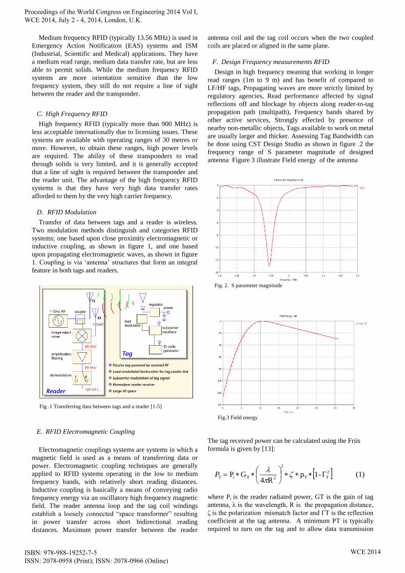
D. RFID Modulation
Transfer of data between tags and a reader is wireless.
Two modulation methods distinguish and categories RFID
systems; one based upon close proximity electromagnetic or
inductive coupling, as shown in figure 1, and one based
upon propagating electromagnetic waves, as shown in figure
1. Coupling is via ‘antenna’ structures that form an integral
feature in both tags and readers.
E. RFID Electromagnetic Coupling
Electromagnetic couplings systems are systems in which a
magnetic field is used as a means of transferring data or
power. Electromagnetic coupling techniques are generally
applied to RFID systems operating in the low to medium
frequency bands, with relatively short reading distances.
Inductive coupling is basically a means of conveying radio
frequency energy via an oscillatory high frequency magnetic
field. The reader antenna loop and the tag coil windings
establish a loosely connected “space transformer” resulting
in power transfer across short bidirectional reading
distances. Maximum power transfer between the reader
antenna coil and the tag coil occurs when the two coupled
coils are placed or aligned in the same plane.
F. Design Frequency measurements RFID
Design in high frequency meaning that working in longer
read ranges (1m to 9 m) and has benefit of compared to
LF/HF tags, Propagating waves are more strictly limited by
regulatory agencies, Read performance affected by signal
reflections off and blockage by objects along reader-to-tag
propagation path (multipath), Frequency bands shared by
other active services, Strongly effected by presence of
nearby non-metallic objects, Tags available to work on metal
are usually larger and thicker. Assessing Tag Bandwidth can
be done using CST Design Studio as shown in figure .2 the
frequency range of S parameter magnitude of designed
antenna Figure 3 illustrate Field energy of the antenna
The tag received power can be calculated using the Friis
formula is given by [13]:
where Pi is the reader radiated power, GT is the gain of tag
antenna, λ is the wavelength, R is the propagation distance,
ζ is the polarization mismatch factor and ΓT is the reflection
coefficient at the tag antenna. A minimum PT is typically
required to turn on the tag and to allow data transmission
Fig. 2. S parameter magnitude
Fig.3 Field energy
Fig .1 Transferring data between tags and a reader [1-5]
(1) -1pR4
GP 2
T
2
2TiT TP
Proceedings of the World Congress on Engineering 2014 Vol I, WCE 2014, July 2 - 4, 2014, London, U.K.
ISBN: 978-988-19252-7-5 ISSN: 2078-0958 (Print); ISSN: 2078-0966 (Online)
WCE 2014

through a backscatter wave. The corresponding
backscattered received power at the reader can be expressed
in the form
where GR is the gain of reader antenna and ΓR is the
reflection coefficient at the reader antenna.
The investigation of EM wave propagation, attenuation,
radiation, and scattering in soil is more complicated. It is
well known that soil electrical properties affect the EM
wave’s propagation properties and thus the radiation and
backscattering characteristics of an RFID system. For oil and
mining sectors, there are many factors that should be
included for a reliable estimate of an RFID system
performance. These include electromagnetic waves
propagation in soil instead of free space (soil frequency-
dependent electrical conductivity (σ) and soil moisture,
distance of propagation (R), etc), potential interferences and
degradation due to real environmental conditions. We will
develop a realistic model in the frequency domain to
investigate EM wave’s propagation and its attenuation in
infinite half-space soil medium. If a plane wave
approximation is used for the attenuation, the depth of
penetration into the materials is known as skin depth. The
skin depth depends on the frequency of the RFID reader
antenna used to transmit EM energy into soil and soil
properties. It is given by the following formula:
where σ is the electrical conductivity and μ is the magnetic
permeability. The corresponding signal attenuation (α) is
given by
In addition to investigating EM wave propagation in soil,
one of our objectives is to implement near field UHF RFID
systems using existing and modified reader modules and tag
ICs. The approach is to use special near-field reader
antennas and tags. New special reader antennas and tags will
be designed and implemented to create strong localized
magnetic field region.
The important parameters that used RFID Antenna Design
are the Gain: Radiation and Directionality of Power this
appear in figure. 4 the far field in all coordinate of the
designed antenna at frequency F=980MHz.
Radio-Frequency Identification (RFID) is the use of RF
radiation to identify physical objects. Automated
identification systems include RFID and bar code systems.
Unlike bar code systems, RFID systems eliminate “line-of-
sight to object” requirements. Figure 5 illustrates a
simplified RFID system. The system uses radio reader-tag
transmissions to identify a tagged object. Each RFID tag
contains an identification number. The RFID reader detects
tags through RF radiation backscattered from RFID tags.
The tag system rectifies the received RF signal to power the
tag circuitry and send a tag identification signal to the reader
[1].
III. RFID SYSTEM APPLICATIONS
IV. RFID OPERATING FREQUENCY BANDS
RFID systems are categorized by; tag powering
techniques, and tag-reader communication protocols. These
aspects help define read range, cost, and available features.
Figure 5.2 lists frequency bands commonly used in RFID
systems. LF (125 and 134 kHz) and HF (13.56 MHz) RFID
systems utilize inductive coupling with typical read ranges
less than 60cm. UHF RFID has read range up to 3m.
Microwave (e.g.: 2.4 GHz) RFID systems with radiative
coupling have read ranges of approximately1m due to
environmental effects, microwave RFID cannot penetrate
water and metal ,along with UHF tags designs that operate
near metal and high water content surfaces, UHF RFID
systems are gaining popularity [3].
Fig .5.1 RFID systems [2]
Fig 5.2: RFID frequency Bands [3]
(3) 2
(2) -1pR4
GGP 2
T
2
4
2
2
TRiR RP
(4) 1- 12
12
Fig. 4. The far field at frequency F=980MHz
Proceedings of the World Congress on Engineering 2014 Vol I, WCE 2014, July 2 - 4, 2014, London, U.K.
ISBN: 978-988-19252-7-5 ISSN: 2078-0958 (Print); ISSN: 2078-0966 (Online)
WCE 2014
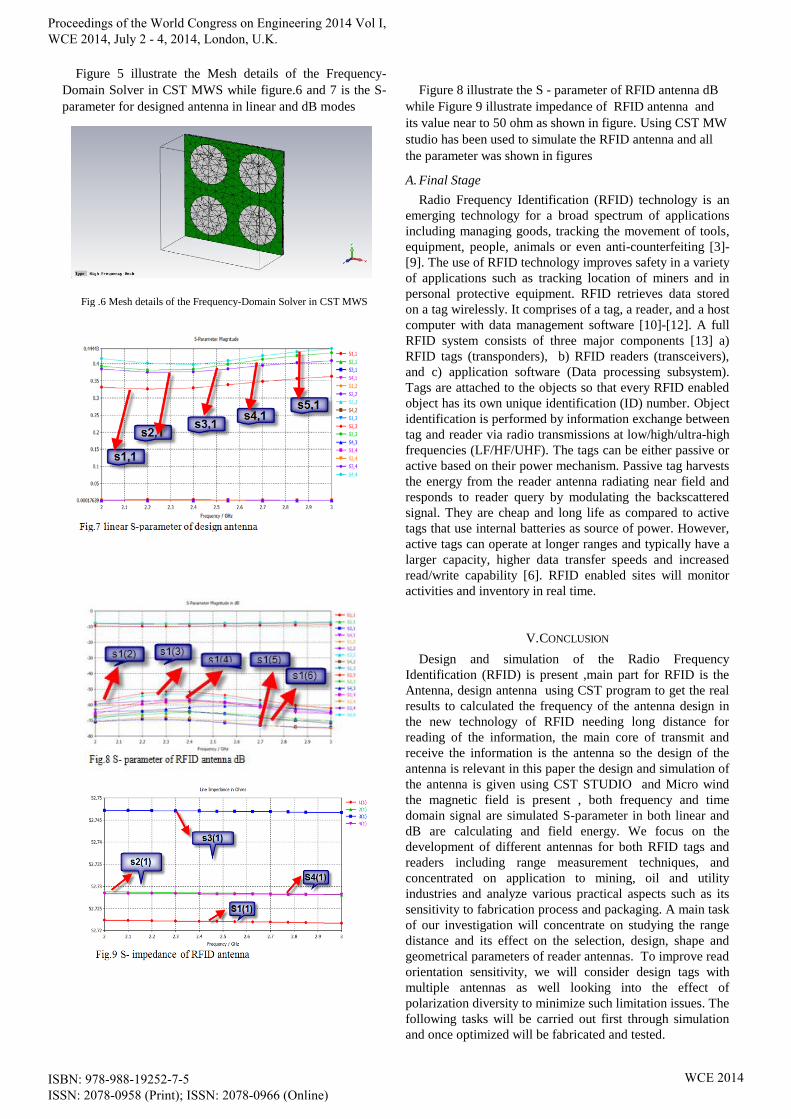
Figure 5 illustrate the Mesh details of the Frequency-
Domain Solver in CST MWS while figure.6 and 7 is the S-
parameter for designed antenna in linear and dB modes
Figure 8 illustrate the S - parameter of RFID antenna dB
while Figure 9 illustrate impedance of RFID antenna and
its value near to 50 ohm as shown in figure. Using CST MW
studio has been used to simulate the RFID antenna and all
the parameter was shown in figures
A. Final Stage
Radio Frequency Identification (RFID) technology is an
emerging technology for a broad spectrum of applications
including managing goods, tracking the movement of tools,
equipment, people, animals or even anti-counterfeiting [3]-
[9]. The use of RFID technology improves safety in a variety
of applications such as tracking location of miners and in
personal protective equipment. RFID retrieves data stored
on a tag wirelessly. It comprises of a tag, a reader, and a host
computer with data management software [10]-[12]. A full
RFID system consists of three major components [13] a)
RFID tags (transponders), b) RFID readers (transceivers),
and c) application software (Data processing subsystem).
Tags are attached to the objects so that every RFID enabled
object has its own unique identification (ID) number. Object
identification is performed by information exchange between
tag and reader via radio transmissions at low/high/ultra-high
frequencies (LF/HF/UHF). The tags can be either passive or
active based on their power mechanism. Passive tag harvests
the energy from the reader antenna radiating near field and
responds to reader query by modulating the backscattered
signal. They are cheap and long life as compared to active
tags that use internal batteries as source of power. However,
active tags can operate at longer ranges and typically have a
larger capacity, higher data transfer speeds and increased
read/write capability [6]. RFID enabled sites will monitor
activities and inventory in real time.
V. CONCLUSION
Design and simulation of the Radio Frequency
Identification (RFID) is present ,main part for RFID is the
Antenna, design antenna using CST program to get the real
results to calculated the frequency of the antenna design in
the new technology of RFID needing long distance for
reading of the information, the main core of transmit and
receive the information is the antenna so the design of the
antenna is relevant in this paper the design and simulation of
the antenna is given using CST STUDIO and Micro wind
the magnetic field is present , both frequency and time
domain signal are simulated S-parameter in both linear and
dB are calculating and field energy. We focus on the
development of different antennas for both RFID tags and
readers including range measurement techniques, and
concentrated on application to mining, oil and utility
industries and analyze various practical aspects such as its
sensitivity to fabrication process and packaging. A main task
of our investigation will concentrate on studying the range
distance and its effect on the selection, design, shape and
geometrical parameters of reader antennas. To improve read
orientation sensitivity, we will consider design tags with
multiple antennas as well looking into the effect of
polarization diversity to minimize such limitation issues. The
following tasks will be carried out first through simulation
and once optimized will be fabricated and tested.
Fig .6 Mesh details of the Frequency-Domain Solver in CST MWS
Fig.7 linear S-parameter of design antenna
Fig.8 S- parameter of RFID antenna dB
Proceedings of the World Congress on Engineering 2014 Vol I, WCE 2014, July 2 - 4, 2014, London, U.K.
ISBN: 978-988-19252-7-5 ISSN: 2078-0958 (Print); ISSN: 2078-0966 (Online)
WCE 2014

ACKNOWLEDGMENT
This work is supported by NPST program by King Saud
University, Project Number 12-ELE2462– 02.
REFERENCES
[1] D. M. Dobkin, The RF in RFID: Passive UHF RFID in Practice.
Newnes, 2007.
[2] "Quick Introduction to RFID," PolyGAIT RFID Tutorial. PolyGAIT,
Web. 14 Jan 2010. http://www.polygait.calpoly.edu//tutorial.htm>.
[3] M. Abbak, and I. Tekin, "RFID Coverage Extension Using
Microstrip-Patch Antenna Array [Wireless Corner]," Antennas and
Propagation Magazine, IEEE , vol.51, no.1, pp.185-191, Feb. 2009 .
[4] H. Stockman, "Communication by Means of Reflected Power,"
Proceedings of the IRE , vol.36, no.10, pp. 1196- 1204, Oct. 1948.
[5] W.-K. Chen, Linear Networks and Systems (Book style). Belmont,
CA: Wadsworth, 1993, pp. 123–135.
[6] S.-L. Chen, and K.-H. Lin, “A slim RFID tag antenna design for
metallic object applications,” IEEE Antennas and Wireless
Propagat. Lett., vol. 7, pp. 729-732, 2008.
[7] G. Marrocco, “The art of UHF RFID antenna design: impedance-
matching and size-reduction techniques,” IEEE Antennas and
Propagat. Magazine, vol. 50, pp. 66-79, 2008.
[8] K. Finkenzeller, RFID Handbook, 2nd ed. New York: Wiley, 2003.
[9] P. V. Nikitin, K. V. S. Rao, S. F. Lam, V. Pillai, R. Martinez, and H.
Heinrich, “Power reflection coefficient analysis for complex
impedances in RFID tag design,” IEEE Trans. Microw. Theory
Tech., vol. 53, pp. 2721–2715, 2005.
[10] M. Hirvonen, K. Jaakkola, P. Pursula, and J. Säily, “Dual-band
platform tolerant antennas for radio-frequency identification,” IEEE
Trans. Antenna Propagat. vol. 54, pp. 2632-2637, 2006.
[11] K. V. Seshagiri Rao, P. V. Nikitin, and S. F. Lam, “Antenna design
for UHF RFID tags: a review and a practical application,” IEEE
Trans. Antenna Propagat. vol. 53, pp. 3870-3876, 2005.
[12] G. Marrocco, “Gain-Optimized self-resonant meander line antennas
for RFID applications,” IEEE Antennas and Wireless Propagat.
Lett., vol. 2, pp. 302-305, 2003
[13] D. J. Hind, "Radio frequency identification and tracking systems in
hazardous areas," Fifth International Conference on Electrical Safety
in Hazardous Environments, pp. 215-227, 1994.
Proceedings of the World Congress on Engineering 2014 Vol I, WCE 2014, July 2 - 4, 2014, London, U.K.
ISBN: 978-988-19252-7-5 ISSN: 2078-0958 (Print); ISSN: 2078-0966 (Online)
WCE 2014