Radiative and Convective Heat Transfer in Buildings · 61 Chapter 3 Radiative and Convective Heat...
24
61 Chapter 3 Radiative and Convective Heat Transfer in Buildings A mixture of conduction, radiation and convection is taking place all over the thermal system of buildings. Wherever a solid surface exists, the convection between the surface and the fluid adjacent to it and the radiation between the surface and the other surfaces take place at the same time. When one can be neglected compared with the other of the two modes of heat transfer, it is quite easy to estimate the heat flow with reasonable accuracy. But when one is comparable to the other in magnitude, the problem must be solved taking account of both radiation and convection simultaneously. In this chapter the combination of radiative heat transfer and convective heat transfer that occurs on the outside and the inside surfaces is discussed. 3.1. FILM COEFFICIENT In the calculation of heat gain or heat loss through exterior walls, a film coefficient is used in the determination of thermal transmittance of walls. The value of the film coefficient is usually higher for the outside surface of the wall than for the inside, because air movement along the surface is different. It is usually implied that both outside and inside film coefficients include the effects of radiation and convection at the surfaces. Hence the value of the film coefficient is the sum of the values of radiative heat transfer coefficient and convective heat transfer coefficient and in this sense the film coefficient is often called the combined surface heat transfer coefficient. The method of handling the radiative and convective heat transfer as a combined effect is convenient in heat transfer calculation, but this tends to lead to misunderstanding. It sometimes happens that the surface receives heat from the fluid by convection and discharges heat to the surroundings by radiation. Failure to recognise real conditions may lead to erroneous results. The outside film coefficient is primarily related to the wind speed and it is often quoted that surface roughness contributes to its value to a considerable degree. The larger the value of the film coefficient, the larger the heat loss or heat gain through walls and in practice higher values are likely to be selected. However, in considering surfaces irradiated by the sun, the heat gain due to solar radiation on the outside surface is greater when wind speed is lower and consequently the film coefficient is lower. It is obvious that the sol-air temperature is higher when the film coefficient is lower, viz.,
Transcript of Radiative and Convective Heat Transfer in Buildings · 61 Chapter 3 Radiative and Convective Heat...

61
Chapter 3
Radiative and Convective Heat Transfer in Buildings
A mixture of conduction, radiation and convection is taking place all over the thermal system of buildings. Wherever a solid surface exists, the convection between the surface and the fluid adjacent to it and the radiation between the surface and the other surfaces take place at the same time. When one can be neglected compared with the other of the two modes of heat transfer, it is quite easy to estimate the heat flow with reasonable accuracy. But when one is comparable to the other in magnitude, the problem must be solved taking account of both radiation and convection simultaneously. In this chapter the combination of radiative heat transfer and convective heat transfer that occurs on the outside and the inside surfaces is discussed.
3.1. FILM COEFFICIENT
In the calculation of heat gain or heat loss through exterior walls, a film coefficient is used in the determination of thermal transmittance of walls. The value of the film coefficient is usually higher for the outside surface of the wall than for the inside, because air movement along the surface is different. It is usually implied that both outside and inside film coefficients include the effects of radiation and convection at the surfaces. Hence the value of the film coefficient is the sum of the values of radiative heat transfer coefficient and convective heat transfer coefficient and in this sense the film coefficient is often called the combined surface heat transfer coefficient. The method of handling the radiative and convective heat transfer as a combined effect is convenient in heat transfer calculation, but this tends to lead to misunderstanding. It sometimes happens that the surface receives heat from the fluid by convection and discharges heat to the surroundings by radiation. Failure to recognise real conditions may lead to erroneous results.
The outside film coefficient is primarily related to the wind speed and it is often quoted that surface roughness contributes to its value to a considerable degree. The larger the value of the film coefficient, the larger the heat loss or heat gain through walls and in practice higher values are likely to be selected. However, in considering surfaces irradiated by the sun, the heat gain due to solar radiation on the outside surface is greater when wind speed is lower and consequently the film coefficient is lower. It is obvious that the sol-air temperature is higher when the film coefficient is lower, viz.,
62
a
0
sε θ
αIaθ += (3.1)
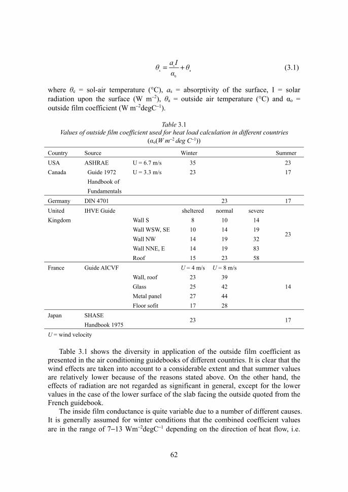
where θe = sol-air temperature (°C), as = absorptivity of the surface, I = solar radiation upon the surface (W m−2), θa = outside air temperature (°C) and αo = outside film coefficient (W m−2degC−1).
Table 3.1 Values of outside film coefficient used for heat load calculation in different countries
(αo(W m−2 deg C−1)) Country Source Winter Summer USA Canada
ASHRAE Guide 1972 Handbook of Fundamentals
U = 6.7 m/s U = 3.3 m/s
35 23
23 17
Germany DIN 4701 23 17 United Kingdom
IHVE Guide Wall S Wall WSW, SE Wall NW Wall NNE, E Roof
sheltered 8
10 14 14 15
normal 10 14 19 19 23
severe 14 19 32 83 58
23
France Guide AICVF Wall, roof Glass Metal panel Floor sofit
U = 4 m/s 23 25 27 17
U = 8 m/s 39 42 44 28
14
Japan SHASE Handbook 1975
23 17
U = wind velocity
Table 3.1 shows the diversity in application of the outside film coefficient as presented in the air conditioning guidebooks of different countries. It is clear that the wind effects are taken into account to a considerable extent and that summer values are relatively lower because of the reasons stated above. On the other hand, the effects of radiation are not regarded as significant in general, except for the lower values in the case of the lower surface of the slab facing the outside quoted from the French guidebook.
The inside film conductance is quite variable due to a number of different causes. It is generally assumed for winter conditions that the combined coefficient values are in the range of 7−13 Wm−2degC−1 depending on the direction of heat flow, i.e.

63
horizontal, downward or upward flow. It must be remembered, however, that this could be applied only to the inside surface of exterior walls or roofs when the temperatures of other interior surfaces of walls, ceiling and floor are equal to the room air temperature. In fact, they are all different. In the case of intermittent air conditioning, the temperature of interior surfaces is quite different from the room air temperature and the effect of radiation and convection at the surface of exterior walls varies accordingly. The real problem occurs when one tries to calculate the heat flow from the interior surface to room air of vice versa, because no one knows the real value of the combined film coefficient for such cases. It is important to note that radiation takes place between one surface and the other and convection between surface and fluid as shown in Fig. 3.1.
Fig. 3.1. Heat flow of exterior wall. θr: room air temperature, θw: interior wall surface
temperature.
3.2. RADIATIVE HEAT TRANSFER COEFFICIENT
From the practical point of view it is very convenient that the rate of radiative heat transfer from one surface to the other is expressed in the form:
121r21r )(α AθθH −= (3.2)
where θ1 and θ2 = temperatures of surface 1 and surface 2 respectively (°C), αr = radiative heat transfer coefficient, Hr12 = rate of radiative heat transfer from surface 1 to surface 2 (W), A1 = area of surface 1.
It is well known, however, that the radiative heat transfer is proportional to the difference of the absolute temperature to the fourth power of the two surfaces. The configuration of two surfaces relative to each other is also important. It is well known that the radiation emitted by a black body is proportional to the absolute temperature of the surface to the fourth power according to Stefan-Boltzmann's Law which states:
4b TσR = (3.3)

64
where Rb = radiation emitted by the perfect black surface that absorbs all radiation of any wavelength (Wm−2), σ = black body constant (= 5・67×10−8Wm−2K−4) and T = absolute temperature of the black surface (K).
The radiation emitted by a general surface is expressed by:
4b εε TσRR == (3.4)
where ε is the emissivity of the surface. Kirchhoff’s Law states that emissivity is equal to absorptivity for a specified temperature of the surface. The fundamental equation of radiative heat transfer between two surfaces is expressed in the following:
)( 42
412112121r TTσFAεεH −= (3.5)
where T1 and T2 = absolute temperatures of surface 1 and 2 respectively (K), ε1 and ε2 = emissivity of surface 1 and 2 respectively, F12 = form factor for surface 2 viewed from surface 1.
Equation (3.5) is valid only when ε1 and ε2 are close to unity but this is often used because most building materials have an emissivity of around 0・9.
Fig. 3.2. Various configurations of two surfaces. Surface 1 is (a) parallel to surface 2, (b) enclosed with surface 2, (c) enclosed with surface 2 and a reflective surface R.
In general, the effective radiation constant combining the black body constant, the emmissivity of two surfaces and the form factor is introduced into the equation, viz.
)( 42
4121121r TTσAH −= (3.6)
where σ12 is the effective radiation constant (Wm−2K−4). For special cases of configuration, σ12 can be expressed as follows as shown in Fig. 3.2:
(a) Two surfaces are parallel. (Fig. 3.2(a)):
σ
εε
σ
1111
21
21−+
= (3.7)

65
(b) Surface 1 is completely enclosed with surface 2. (Fig. 3.2(b)):
σ
εAA
ε
σ
−+
=111
1
22
1
1
21 (3.8)
(c) There is a reflective surface other than surface 1 and surface 2. (Fig. 3.2(c)):
σ
εAA
εF
σ
−+
−+
′
=11111
1
22
1
121
21 (3.9)
Fig. 3.3. Mean temperature of two surfaces.
where F′12 is F12 plus the fraction of the radiation reaching surface 2 after repetition of reflection by the reflecting surface R to be expressed as:
R2R1
R21R1212 FF
FFFF'+
+= (3.10)
where F1R, FR1 and FR2 are form factors from the surface of the left subscript to see the surface of the right subscript.
Equating the eqns. (3.2) and (3.5) αr can be derived on an approximate basis. From the relationship as shown in Fig. 3.3, when ΔT is taken as:
ΔTT TΔTTT −=+= m2m 1
where Tm is average temperature of T1 and T2, eqn. (3.6) may be rewritten as:
])()[( 4m
4m2112 r1 ΔTTΔTTσAH −−+=
66
≑ 3m211 .Δ8 T TσA ⋅
)(4 213
m211 θθTσA −=
Hence
αr ≑ 3m21 Tσ4 (3.11)
For example, in the case of eqn. (3.7), where ε1 = ε2 = 0・9 and Tm = 300 K, it follows that:
1238 CdegWm153001067583304 −−− ⋅=××⋅×⋅×=rα
The radiative heat transfer coefficient αr thus derived is often used in the approximate estimation of radiation exchange between two surfaces.
3.3. CONVECTIVE HEAT TRANSFER COEFFICIENT
The convective heat transfer coefficient is also a useful invention whereby the heat transfer by convection between the solid surface and the fluid in the vicinity of the surface can easily be estimated by a simple formula:
)(α a0cc θθq −= (3.12)
where qc = the rate of convective heat transfer (Wm−2), αc = convective heat transfer coefficient (Wm−2degC−1), θ0 = solid surface temperature (°C), and θa = ambient fluid temperature (°C).
Because of the complexity in the mechanism of convective heat transfer, the value of αc is dependent upon many different factors such as (1) configuration, (2) velocity of fluid flow, (3) temperature difference between surface and fluid and (4) physical properties of the fluid such as thermal conductivity, kinematic viscosity, specific weight, specific heat, thermal diffusivity, viscosity and volumetric expansion coefficient.
In expressing the convective heat transfer coefficient for such a great number of factors, the method known as dimensional analysis is normally used. The idea of the dimensional analysis is to decrease the number of variables associated with the convective heat transfer coefficient through the theoretical and experimental determination of the exponents of those dimensionless numbers for which a specific relationship can be established. The following is a list of the dimensionless numbers often used in air conditioning.

67

68
Nusselt number Nu = λdcα Reynolds number Re = νud Prandtl number Pr = aν (3.13) Grashof number Gr = 23dΔ νθβg Graetz number Gz = lλγuCdπ p 42
It is important to note that the convective heat transfer coefficient occurs in the Nusselt number. Thus the relationship among the dimensionless numbers can be expressed in general as:
dcba . k GzGrPrReNu = (3.14)
where k, a, b, c and d are constants determined by the different conditions as shown in Table 3.2.
It must be remembered that the relationship discussed in the mechanical engineering field is valid only when the fluid flows uniformly along the surface. For example, the relationship for laminar flow of forced convection along a flat plate surface is expressed by the relationship of three dimensionless numbers, namely:
333.05.0 PrRe6640Nu .⋅= (3.14a)
Six variables such as αc, d, λ, u, v and a are involved in the dimensionless numbers given by eqn. (3.14a).
3.4. RADIATION FROM THE ATMOSPHERE
Any surface on the earth emits radiation to the sky according to the surface temperature and at the same time receives radiation from the atmosphere, the balance being called the effective radiation. Since this amounts to as high as 100 Wm−2 during clear nights, this is often called nocturnal radiation. This high amount occurs because the atmosphere emits much less radiation than the black solid surface having the same temperature as the ambient air.
Brunt found out that the long-wave radiation falling on the earth is essentially dependent on the water vapour content in the atmosphere and presented the following formula, viz.,
eba +=Br (3.15)
where e = water vapour pressure (mb), a and b = constants. Br is called the emissivity of atmosphere, meaning the ratio of radiation from the atmosphere to the radiation from a black hemisphere whose temperature is equal to the ambient air

69
temperature. The constants a and b have been obtained by a number of meteorologists and the values proposed by Yamamoto are introduced here [3.1], viz.,
a = 0・51 and b = 0・066
In the case when the water vapour pressure of f (kPa) is used instead of e (mb), b = 0・209and the amount of atmospheric radiation qa (Wm−2) is to be expressed by:
)2090510(4a a fσTq ⋅+⋅= (3.16)
where Ta = absolute temperature of ambient air (K). In reality, the atmospheric radiation is the radiation emitted by the water vapour particles in the atmosphere. In consequence, it can be considered that the lower the water vapour content of the atmosphere, the larger the effective radiation emitted from the surface on the earth to the outer space.
It would be interesting to calculate the hypothetical temperature of the sky hemisphere if the sky vault were a black solid hemispherical surface under the conditions of, say outside air temperature −10°C and relative humidity 90%.
As the saturated water vapour pressure for −10°C is 0・286 kPa, the water vapour pressure at 90% relative humidity can be obtained as 3180902860f ⋅=⋅÷⋅= Hence 629031802090510 ⋅=⋅×⋅+⋅=Br .
The hypothetical temperature of the sky hemisphere Tx (K) can be calculated from the condition that .σTσT 4
a 4
x 6290 ⋅= Hence Tx = 4 6290 ⋅ (273−10) = 234K = −39°C. This means that to neglect the effects of atmospheric radiation would possibly give rise to a considerable error in heat loss calculations.
Brunt’s formula is based on the clear night sky. For cloudy sky the formula could be modified by using Philipps’ research results [3.2]. Philipps made a comparison of the atmospheric radiation between clear and cloudy days and obtained the following results, viz., with reference to Fig. 3.4:
Fig. 3.4. Long wavelength radiation exchange at ground surface.
)1()( co4e
4e KRTσRTσ −−=− (3.17)
where Te = ground surface temperature (K), R, Ro = atmospheric radiation on cloudy and clear days respectively (Wm−2), Kc = reduction factor dependent upon the height

70
of cloud as shown in Table 3.3.
Table 3.3 Kc value
Since Br4
ao TσR = , it can be seen that the atmospheric radiation in cloudy conditions is also related to the ground surface temperature as expressed by:
c4ec
4a )1(Br KTσKTσR +−= (3.18)
When part of the sky is overcast, the atmospheric radiation in general qaG can be expressed by the following, taking cc as total cloud amount in tenths.
4c cc
4a cc
ccoaG
)1( )1(
σTKcBrσTKcRccRq
+−=+−=
(3.19)
Where cc is cloud cover ratio:
10c
ccc =
3.5. HEAT BALANCE AT THE OUTSIDE SURFACE OF BUILDINGS
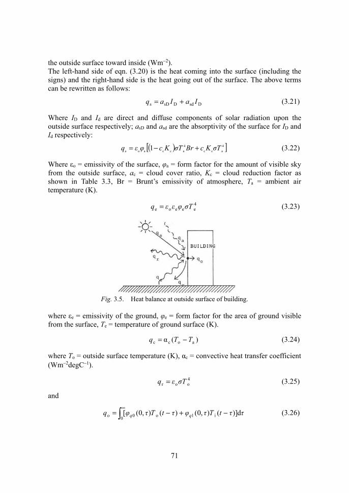
At the outside surface, of a building, there are always two components of heat, that coming into and that leaving the surface. The temperature of the surface is determined in such a way that the heat balance is to be maintained. The heat balance equation at the outside surface can be expressed as in the following in reference to Fig. 3.5.
orceas qqqqqq ++=++ (3.20)
where qs = solar radiation absorbed by the surface (Wm−2), qa = atmospheric radiation absorbed by the surface (Wm−2), qe = radiation from ground absorbed by the surface (Wm−2), qc = convective heat transfer from the surface to the ambient air (Wm−2), qr = radiation emitted by the surface (Wm−2) and qo = heat conduction from
71
the outside surface toward inside (Wm−2). The left-hand side of eqn. (3.20) is the heat coming into the surface (including the signs) and the right-hand side is the heat going out of the surface. The above terms can be rewritten as follows:
DsdDsDs IaIaq += (3.21)
Where ID and Id are direct and diffuse components of solar radiation upon the outside surface respectively; asD and asd are the absorptivity of the surface for ID and Id respectively:
( )[ ]4a cc
4a ccaoa 1 σTKcBrσTKcφεq +−= (3.22)
Where εo = emissivity of the surface, φa = form factor for the amount of visible sky from the outside surface, ac = cloud cover ratio, Kc = cloud reduction factor as shown in Table 3.3, Br = Brunt’s emissivity of atmosphere, Ta = ambient air temperature (K).
4eeeoe Tσφεεq = (3.23)
Fig. 3.5. Heat balance at outside surface of building.
where εe = emissivity of the ground, φe = form factor for the area of ground visible from the surface, Te = temperature of ground surface (K).
)(α aocc TTq −= (3.24)
where To = outside surface temperature (K), αc = convective heat transfer coefficient (Wm−2degC−1).
4oor Tσεq = (3.25)
and
∞
−+−=0 i1o0o d)](),0()(),0([ ττtTτφτtTτφq q q (3.26)

72
where φq0(0, τ), φq1(0, τ) are impulse responses of the outside surface heat flow against the outside surface temperature and inside surface temperature respectively (Wm−2deg C−1), Ti(t) = inside surface temperature at time t (K).
Using response factors instead of impulse response, qo may be expressed in the form of a time series as in the following:
∞
=−− ⋅+⋅=
0jjni,jjno,jno, )( TYTXq (3.27)
where Xj and Yj are response factors of the exterior wall (Wm−2degC−1), To,n, Ti,n are outside and inside surface temperature of the exterior wall respectively at time t = nΔt(K), qo,n is the heat flow at the outside surface of exterior wall at time t = nΔt.
Assuming that the instantaneous heat transfer through the exterior wall is proportional to the temperature difference across the wall, the following comes true:
)( oo τTTKq −′= (3.28)
where K′ = overall heat transfer coefficient from the outside surface of the exterior wall to the room air (Wm−2degC−1), Tr = room air temperature (K).
Hence the heat balance equation can be solved for outside surface temperature applying eqn. (3.21)−(3.28) to eqn. (3.20).
The heat balance equation, assuming eqn. (3.28) is valid, can be reduced to:
)(α
1 4oo
co TσεA
KT −
+′= (3.29)
where
acrc4aeeo
4aao αBr TTKIaTσφεεTσφεA +′+++= (3.30)
As this equation includes to in the right-hand side of it, iteration is necessary to arrive at the real value of To.
Example: Obtain heat loss from a double pane glass window under the following conditions in the winter evening of clear sky.
K273,mmHg4,0 , CdegWm12α
,0,90ε,920ε,50 , CdegWm3′
ea12
c
eoea12
=====
=⋅=⋅=⋅===−
−
TTfI
a φφ K c
Solution:
(1) Value A is calculated first from eqn. (3.30)
0343832731229337326755090
)40760510(73267550909204
4
⋅=×+×+⋅×⋅×⋅×⋅+
⋅+⋅⋅×⋅×⋅×⋅×⋅=
A

73
(2) )034383675920(123
1 4oo ⋅+×⋅×⋅−
+= TT
(3) Assuming To = 273, eqn. (3.29) gives
89272)03438375289(151
o ⋅=⋅×⋅−=T
(4) Assuming To =272・9, it gives To = 272・91
(5) This is quite close to the assumed value. Using To = 272・9, the heat loss is:
2Wm360)9272293(3 −⋅=⋅−= q
By way of comparison, if one took the value of thermal transmittance as:
402
31
121
1 ⋅=+
=K
Neglecting the atmospheric radiation, the heat gain could be estimated as:
2Wm48)9272293(402 −=⋅−⋅= q
This is smaller than the above value of 60.3 by about 20%.
The above procedure is not complicated because the iteration need not be done more than twice, even if the value in the first assumption is quite far from the true value.
When the combined radiative and convective film coefficient is used in calculation, the equivalent temperature drop for nocturnal radiation may be introduced into the heat loss calculation. It must be remembered that the radiative component in the film coefficient is defined as the radiative heat transfer coefficient between a point on the outside surface and the hypothetical black hemispherical surface surrounding the point as shown in Fig. 3.6, namely:
Fig. 3.6. Presumed black sky vault with air temperature.

74
4a
4o0aoro ε)(α TσTσTT −=− (3.31)
and rocoo ααα += (3.32)
where αco, αro = outside convective and radiative heat transfer coefficients respectively (Wm−2degC−1).
Then the equation of heat loss from the outside surface to the ambient atmosphere is given by:
zaooo )(α qθθq +−= (3.33)
where θo = outside surface temperature (°C), θa = ambient air temperature (°C) and:
( )[ ]{ }4e eecccca
4a oz 11 σTεφKaBrKaφ σσεq −+−−= (3.34)
Equation (3.33) may be expressed by applying the sol-air temperature concept to nocturnal radiation such as,
−−=
o
zaooo α
α qθθq (3.35)
The last term in this equation qz/αo may be called equivalent temperature drop due to nocturnal radiation against the ambient temperature. Then the heat gain, including the effect of solar radiation, is expressed by
−−−= o
o
z
o
saoo αα
α θqq
θq (3.36)
−−−= r
o
z
o
sa αα
θqq
θK (3.37)
where θr = room air temperature (°C), K = overall heat transfer coefficient across the wall (Wm−2degC−1), qs = solar radiation absorbed at the outside surface (Wm−2).
The advantage of using eqn. (3.37) is that heat gain can be obtained without deriving the outside surface temperature as required for the method using eqn. (3.33). It must be noted, however, that αr should be determined as accurately as possible by adequate assumptions.
If αr = 5(Wm−2degC−1) is used in the preceding example,
552
31
171
1and17125αo ⋅=+
==+= K
( )( ) 46637214170210920
732675905.0)]40760510(5.01[(732675920 44z
⋅=⋅−⋅×⋅=⋅×⋅×⋅×−⋅+⋅−⋅×⋅×⋅= q
75
2
o
Wm5607323552
174663020552
−⋅=⋅×⋅=
⋅−−⋅=
q
This turns out quite close to 60・3 which was derived from the more rigorous solution using an iteration procedure. The error could be greater for a sunlit surface when the value of αr could not be determined accurately and for cloudy days.
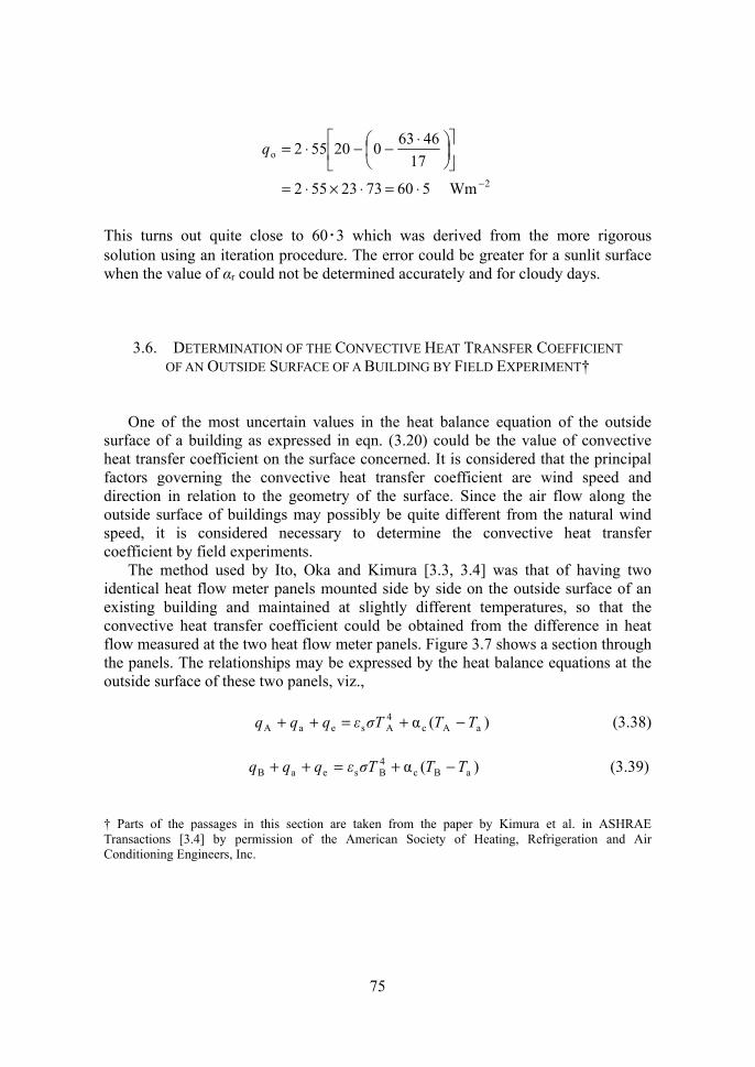
3.6. DETERMINATION OF THE CONVECTIVE HEAT TRANSFER COEFFICIENT OF AN OUTSIDE SURFACE OF A BUILDING BY FIELD EXPERIMENT†
One of the most uncertain values in the heat balance equation of the outside surface of a building as expressed in eqn. (3.20) could be the value of convective heat transfer coefficient on the surface concerned. It is considered that the principal factors governing the convective heat transfer coefficient are wind speed and direction in relation to the geometry of the surface. Since the air flow along the outside surface of buildings may possibly be quite different from the natural wind speed, it is considered necessary to determine the convective heat transfer coefficient by field experiments.
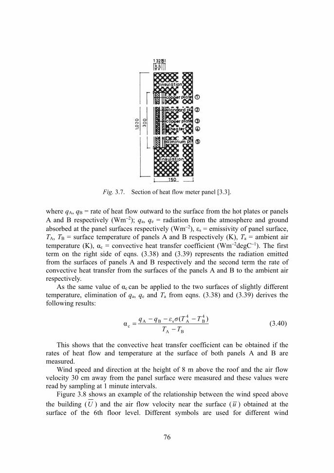
The method used by Ito, Oka and Kimura [3.3, 3.4] was that of having two identical heat flow meter panels mounted side by side on the outside surface of an existing building and maintained at slightly different temperatures, so that the convective heat transfer coefficient could be obtained from the difference in heat flow measured at the two heat flow meter panels. Figure 3.7 shows a section through the panels. The relationships may be expressed by the heat balance equations at the outside surface of these two panels, viz.,
)(α aAc4AseaA TTTσεqqq −+=++ (3.38)
)(α aBc
4BseaB TTTσεqqq −+=++ (3.39)
† Parts of the passages in this section are taken from the paper by Kimura et al. in ASHRAE Transactions [3.4] by permission of the American Society of Heating, Refrigeration and Air Conditioning Engineers, Inc.
76
Fig. 3.7. Section of heat flow meter panel [3.3].
where qA, qB = rate of heat flow outward to the surface from the hot plates or panels A and B respectively (Wm−2); qa, qe = radiation from the atmosphere and ground absorbed at the panel surfaces respectively (Wm−2), εs = emissivity of panel surface, TA, TB = surface temperature of panels A and B respectively (K), Ta = ambient air temperature (K), αc = convective heat transfer coefficient (Wm−2degC−1). The first term on the right side of eqns. (3.38) and (3.39) represents the radiation emitted from the surfaces of panels A and B respectively and the second term the rate of convective heat transfer from the surfaces of the panels A and B to the ambient air respectively.
As the same value of αc can be applied to the two surfaces of slightly different temperature, elimination of qa, qe and Ta from eqns. (3.38) and (3.39) derives the following results:
BA
4B
4AsBA
c)(
αTT
TTσεqq
−−−−
= (3.40)
This shows that the convective heat transfer coefficient can be obtained if the rates of heat flow and temperature at the surface of both panels A and B are measured.
Wind speed and direction at the height of 8 m above the roof and the air flow velocity 30 cm away from the panel surface were measured and these values were read by sampling at 1 minute intervals.
Figure 3.8 shows an example of the relationship between the wind speed above the building (U ) and the air flow velocity near the surface ( u ) obtained at the surface of the 6th floor level. Different symbols are used for different wind

77
directions to the wall surface as indicated. It can be observed that u is approximately
31 to
51 of U when U is greater than 2m/s and the surface is
windward, and that u remains around 0・5m/s when the surface is leeward or when U is less than 2m/s and the surface is windward.
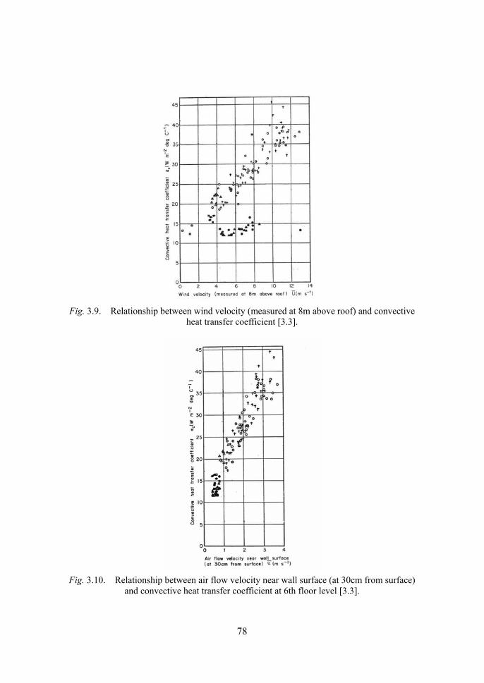
Figure 3.9 shows the plots of the convective heat transfer coefficient (αc)
calculated according to the above procedure against the wind speed above the building (U ) using the same symbols corresponding to the cases in Fig. 3.8.
It is seen that αc increases with the increase of U when the surface is windward and αc remains around 14 Wm−2degC−1 when the surface is leeward. Although the points are quite scattered, it is important to note that αc can be as low as 12Wm−2degC−1.
Plots of the convective heat transfer coefficient (αc) against the air flow velocity near the surface ( u ) are shown in Fig. 3.10. Here the scatter of the points is less divergent than the scatter in Fig. 3.9 and this u − αc relationship is mostly independent of the relative wind direction to the surface.
This would imply that the relationship between the convective heat transfer coefficient and the wind speed and direction might possibly be broken into two relationships, U − u relationship and u − αc relationship, using the air flow velocity near the surface as a reference parameter. It was found in additional tests that there was no significant difference in the U − u relationship when the value of air flow velocity was measured 10 cm or 20 cm away from the surface, instead of 30cm.
78
Fig. 3.9. Relationship between wind velocity (measured at 8m above roof) and convective
heat transfer coefficient [3.3].
Fig. 3.10. Relationship between air flow velocity near wall surface (at 30cm from surface)
and convective heat transfer coefficient at 6th floor level [3.3].

79
Eight sets of measurements similar to the above were made at different locations on the building surface as illustrated in Fig. 3.11.
As in the preceding example it was found again that the scatter of points in the U − αc relationship was very divergent and quite different with different cases, whereas the scatter in the u − αc relationship as shown in Fig. 3.12 was less divergent, independent of relative wind direction to the surface, and fairly consistent with different panel locations showing the patterns quite similar to that shown in Fig. 3.10.
Fig. 3.11. Positions and symbols of the measurement made at the north wall surface
of test building [3.3]
Fig. 3.12. Relationship between air flow velocity near the wall surface [3.3], (left) at the
3rd floor level, (right) at the 4th floor level.

80
The difference in the U −αc relationship with different locations on the building surface was apparent. A slight increase in u /U with height for the middle part of the building and a slight increase in u /U with distance toward the edge of the building for the 3rd and 4th floor are noticeable. This might have been to a high degree due to the configuration of surroundings as well as that of the building concerned.
In addition, it was often observed that the values were as low as 6Wm−2degC−1 on either floor under calm conditions or on the leeward surface.
It can be concluded that the test results on an actual building did not agree with the conventional relationships between convective heat transfer coefficient and air flow velocity along the surface if the wind speed was used as the air flow velocity in the formulas. This is because of the characteristic difference between convective heat transfer in the wind tunnel and in the actual building. When the building surface is leeward, the effect of wind speed is hardly observed.
It is obvious that the relationship between wind speed and the convective heat transfer coefficient can be broken down into two characteristic relationships: the relationship between wind speed and air flow velocity near the surface which is dependent upon the relative wind direction to the surface and the surface location in the building, and the relationship between convective heat transfer coefficient and the air flow velocity near the surface. The latter relationship is found to be fairly consistent and independent of either the wind direction relative to the surface or the surface location on the building. This breakdown seems necessary for the estimation of the convective heat transfer coefficient, especially when the air temperature near the surface is different from the ambient dry bulb temperature, although the experiments under summer conditions have not been carried out.
The following is an algorithm for computer calculation of the convective heat transfer coefficient on the outside surface derived from the experiments described in the above.
Input U = wind speed in general (m/s) θ = wind direction (angle measured clockwise from north) (degrees) ε = wall azimuth (positive degrees westward from south and negative
eastward) Output u = air velocity near the outside surface (m/s) αc = convective heat transfer coefficient (Wm−2degC−1)
Calculation sequence (1) Calculate wind direction relative to the wall surface γ
γγ γ θεγ
−=>−+=360,180If
180 (3.41)
If -45≦γ≦45, the surface is windward and otherwise the surface is leeward
(2) Calculate air velocity near the outside surface u

81
(i) If the surface is windward:
502for2502for
⋅=≤⋅=>
u U Uu U
(3.42)
(ii) If the surface is leeward:
Uu 05030 ⋅+⋅= (3.43)
(3) Calculate convective heat transfer coefficient αc
uαc 6774 ⋅+⋅= (3.44)
3.7. RADIATION AND CONVECTION HEAT EXCHANGE INSIDE THE ROOM
Radiation and convection are always taking place in a mixed mode inside the room whether it is air-conditioned or not. Radiation occurs among the inside surfaces of the room and convection occurs between the air in the room and the surfaces of the room.
The values of the inside surface heat transfer coefficient used in the calculations of heat transfer across the wall are given in Table 3.4, where the values are different with the direction of heat flow: upward, downward or horizontally and these values include the effects of both radiation and convection. It must be remembered,
Table 3.4 Inside film coefficient αi (Wm−2degC−1)
82
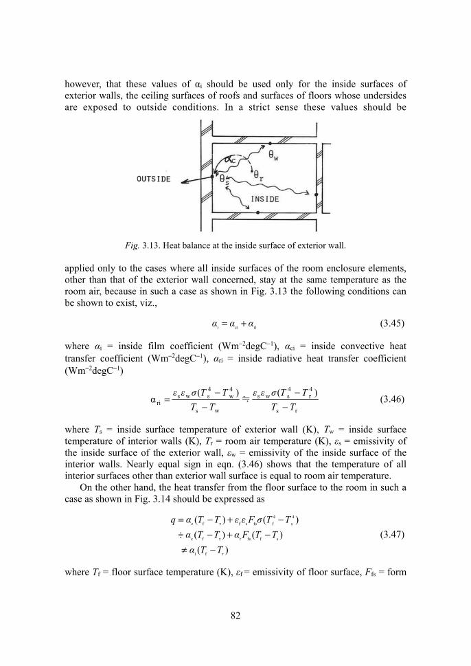
however, that these values of αi should be used only for the inside surfaces of exterior walls, the ceiling surfaces of roofs and surfaces of floors whose undersides are exposed to outside conditions. In a strict sense these values should be
Fig. 3.13. Heat balance at the inside surface of exterior wall.
applied only to the cases where all inside surfaces of the room enclosure elements, other than that of the exterior wall concerned, stay at the same temperature as the room air, because in such a case as shown in Fig. 3.13 the following conditions can be shown to exist, viz.,
ricii ααα += (3.45)
where αi = inside film coefficient (Wm−2degC−1), αci = inside convective heat transfer coefficient (Wm−2degC−1), αri = inside radiative heat transfer coefficient (Wm−2degC−1)
rs
4r
4sws
ws
4w
4sws
ri)()(
αTT
TTσεεTT
TTσεε
−−
−−
= ≒ (3.46)
where Ts = inside surface temperature of exterior wall (K), Tw = inside surface temperature of interior walls (K), Tr = room air temperature (K), εs = emissivity of the inside surface of the exterior wall, εw = emissivity of the inside surface of the interior walls. Nearly equal sign in eqn. (3.46) shows that the temperature of all interior surfaces other than exterior wall surface is equal to room air temperature.
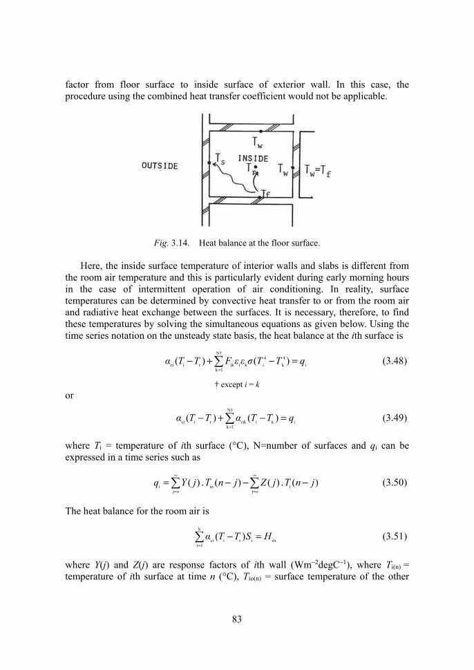
On the other hand, the heat transfer from the floor surface to the room in such a case as shown in Fig. 3.14 should be expressed as
)(
)()( )()(
fi
sffsrτfc
4s
4f fssfτfc
τTTαTTFαTTα
TTσFεεTTαq
−≠−+−
−+−= (3.47)
where Tf = floor surface temperature (K), εf = emissivity of floor surface, Ffs = form
≑
83
factor from floor surface to inside surface of exterior wall. In this case, the procedure using the combined heat transfer coefficient would not be applicable.
Fig. 3.14. Heat balance at the floor surface.
Here, the inside surface temperature of interior walls and slabs is different from
the room air temperature and this is particularly evident during early morning hours in the case of intermittent operation of air conditioning. In reality, surface temperatures can be determined by convective heat transfer to or from the room air and radiative heat exchange between the surfaces. It is necessary, therefore, to find these temperatures by solving the simultaneous equations as given below. Using the time series notation on the unsteady state basis, the heat balance at the ith surface is
i
N†
1k
4k
4i kiikrici )()( qTTσεεFTTα =−+−
= (3.48)
† except i = k or
=
=−+−N†
1kikirikrici )()( qTTαTTα (3.49)
where Ti = temperature of ith surface (°C), N=number of surfaces and qi can be expressed in a time series such as
)( . )()( . )( ij
ioj
i jnTjZjnTjYqoo
−−−= ∞
=
∞
= (3.50)
The heat balance for the room air is
exiri
k
1ici )( HSTTα =−
= (3.51)
where Y(j) and Z(j) are response factors of ith wall (Wm−2degC−1), where Ti(n) = temperature of ith surface at time n (°C), Tio(n) = surface temperature of the other

84
side of ith wall (°C), Si = area of ith surface (m2), Hex = heat extraction from the space (W). This deals only with sensible heat and latent heat is considered separately. These simultaneous equations may be expressed in a matrix form as shown below referring to Fig. 3.15.
=
−
−+−−−
−−−+−−−−−+
=
ex
2
1
1cc33c22c11c
crc3r2r1r
2c2r23r2r2c21r
1c1r13r12r1r1c
2
1
ααααα
αααααα
αααααααααααα
Hq
SSSSS
TT
TT
kk
iiikk
kkkkkk
k
k
r
k
(3.52)
Fig. 3.15. Radiation exchange at inside surface.
where
2)( 3
kikiikrik
N†
1krikrik
/TTσεεFα
αα
+=
== (3.53)
The heat flow qi is again a function of the temperature at the other surface of the enclosure, which in most cases is unknown. Then another set of simultaneous equations must be combined with the above equations. It is necessary, therefore, to set up assumptions so that the simultaneous equations can be solved. The most general one would be that the temperature on the other side of enclosure would be assumed on a reasonably realistic basis.
It would be interesting to construct a model for the entire thermal system of a building including all boundary conditions, but this might become too complicated to yield a final solution.
![Natural convective magneto-nanofluid flow and radiative ... radiative heat transfer past a moving vertical plate ... Sheik- holeslami and Ganji ... and Oztop and Abu-Nada [43] is given](https://static.fdocuments.net/doc/165x107/5ad64e5a7f8b9a5b538b51fc/natural-convective-magneto-nanofluid-flow-and-radiative-radiative-heat-transfer.jpg)