3300 Xl-8mm-Proximity-transducer-system Datasheet 141194 Cda 000 0 (1)
Upload
duongduongCategory
view
230download
0
Specifications and Ordering Information Part Number 141595-01
Rev. F(07/13)
Page 1 of 30
Bently Nevada* Asset Condition Monitoring Radiation Resistant Proximity Transducer System
Description The Radiation Resistant Proximity Transducer System consists of:
a 0.300 or 0.420 Radiation Resistant probe a Radiation Resistant extension cable a XL Radiation Resistant Proximitor* Sensor
The Bently Nevada Radiation Resistant Proximity Transducer System permits machinery monitoring on pumps, motors, and other rotating machinery operating in gamma-radiation environments. The Radiation Resistant Proximity Transducer System maintains its signal integrity better than standard Bently Nevada systems when exposed to gamma-radiation environments. The systems are available with probe diameters of 0.300 and 0.420 inches, each with different linear ranges. The 0.300 system comes in 15-, 40-, and 110-foot lengths while the 0.420 system is available in the 15-foot length only. The longer 40- and 110-foot systems allow you to remotely locate the Proximitor Sensor minimizing the rate of radiation exposure and extending the operational life of the Proximitor Sensor.
The 330280 Proximitor Sensor is backward compatible and interchangeable with the 36363 0.300 Proximitor Sensor, and the 330281 Proximitor Sensor is backward compatible and interchangeable with the 23268 0.420 Proximitor Sensor.
The Radiation Resistant Proximity Transducer System is compatible with 3300 and 3500 Series Monitoring Systems that have been modified to use the previous 36363 or 23268 Radiation Resistant Systems. Please contact your local sales professional for information on specific monitor modifications.
Proximitor Sensor
The XL Proximitor Sensor incorporates numerous improvements over previous designs. Its physical packaging permits high-density DIN-rail installation. It can also be mounted in a traditional panel mount configuration, where it shares an identical “footprint” to older 4-hole mounted Proximitor Sensor designs. Both mounting base options provide electrical isolation, and eliminate the need for separate isolator plates. Improved RFI/EMI immunity allows the XL Proximitor Sensor to achieve European CE mark approvals without requiring special shielded conduit or metallic housings, resulting in lower installation costs and complexity.
The XL’s SpringLoc terminal strips require no special installation tools and facilitate faster, more robust field wiring connections by eliminating screw-type clamping mechanisms that can loosen.

Specifications and Ordering Information Part Number 141595-01
Rev. F(07/13)
Page 2 of 30
Specifications Unless otherwise noted, the following specifications are for a Proximitor* Sensor, extension cable and probe at +22°C (+72 °F) with a -24 Vdc power supply, a 10 k load, and an AISI E4140 steel target. Unless noted, these specifications apply before irradiation.
Electrical
Accepts one non-contacting Radiation Resistant Proximity Probe and Extension Cable.
Power:
Requires -17.5 Vdc to -26 Vdc without barriers at 18 mA maximum consumption. Operation at a more positive voltage than -23.5 Vdc can result in reduced linear range.
Output Resistance:
50
0.300 Probe dc resistance (nominal) (Rprobe):
1.6 + 0.426 /m (0.130 /ft)
0.420 Probe dc resistance (nominal) (Rprobe):
2.5 + 0.410 /m (0.125 /ft)
Extension cable dc resistance (nominal)
Center conductor (Rcore):
0.36 /m (0.11 /ft)
Shield conductor (Rjacket):
0.023 /m (0.007 /ft)
Extension cable capacitance (nominal):
63 pF/m (19.2 pF/ft)
Field wiring:
0.2 to 1.5 mm2 (16 to 24 AWG) Recommend using 3-conductor shielded triax cable field wiring. Maximum length of 305 metres (1,000 feet) between the XL Proximitor Sensor and the monitor. See the frequency response graph for signal roll off at high frequencies when using longer field wiring lengths.
Linear Range:
0.300 inch, 15-foot system:
Linear range begins at –4.5 Vdc, approximately 0.5 mm (20 mils) from target and is from 0.5 to 1.75 mm (20 to 70 mils).
0.300 inch, 40-foot system:
Linear range begins at –4.5 Vdc, approximately 1 mm (40 mils) from target and is from 1 to 2.25 mm (40 to 90 mils).
0.300 inch, 110-foot system:
Linear range begins at –4.5 Vdc, approximately 1 mm (40 mils) from target and is from 1 to 2.25 mm (40 to 90 mils).
0.420 inch, 15-foot system:
Linear range begins at –5.0 Vdc, approximately 1.0 mm (40 mils) from target and is from 1.0 to 3.3 mm (40 to 130 mils).

Specifications and Ordering Information Part Number 141595-01
Rev. F(07/13)
Page 3 of 30
Incremental Scale Factor (ISF)
0.300 inch, 15-foot system:
3.94 mV/µm (100 mV/mil) ±15% including interchangeability error when measured in increments of 0.25 mm (10 mils) over the 1.25 mm (50 mil) linear range.
0.300 inch, 40-foot system:
3.94 mV/µm (100 mV/mil) ±17% including interchangeability error when measured in increments of 0.25 mm (10 mils) over the 1.25 mm (50 mil) linear range.
0.300 inch, 110-foot system:
3.94 mV/µm (100 mV/mil) ±20% including interchangeability error when measured in increments of 0.25 mm (10 mils) over the 1.25 mm (50 mil) linear range.
0.420 inch, 15-foot system:
3.94 mV/µm (100 mV/mil) ±15% including interchangeability error when measured in increments of 0.25 mm (10 mils) over the 2.25 mm (90 mil) linear range.
Frequency Response:
15-foot systems:
0 to 10 kHz: +0, -3dB, with up to 305 metres (1000 feet) of field wiring.
40-foot system:
0 to 9 kHz: +0, -3dB, with up to 305 metres (1000 feet) of field wiring.
110-foot system:
0 to 5 kHz: +0, -3dB, with up to 305 metres (1000 feet) of field wiring.
Mechanical
Probe tip material:
Fiberglass reinforced epoxy with anhydride curing.
Probe case material:
300 series stainless steel
Probe and Extension cable specifications:
85 coaxial, Tefzel® insulated cable.
Proximitor sensor material:
A308 aluminum
Extension cable armor (optional):
Flexible stainless steel with Tefzel® outer jacket.
Tensile strength (maximum rated):
133 N (30.0 pounds) probe case to probe lead and probe lead to extension cable connectors.
Connector material:
Gold-plated brass
Probe case torque:
33.9 Nm (300 inlb)
Total System Weight (typical):
1.0 kg (2.2 lb)

Specifications and Ordering Information Part Number 141595-01
Rev. F(07/13)
Page 4 of 30
Environmental Limits
Probe operating and storage temperature range:
-29 °C to +150 °C (-20 °F to +302 °F)
Extension Cable operating and storage temperature range:
-29 °C to +150 °C (-20 °F to +302 °F)
Proximitor sensor operating and storage temperature range:
-51 °C to +100 °C (-60 °F to +212 °F)
Relative humidity:
Less than a 3% change in Average Scale Factor (ASF) when tested in accordance with IEC standard 68-2-66.
System radiation limit:
6.0 Mrads (gamma maximum integrated dose)
Note: We recommend a maximum 6
Mrads exposure. See the Summary
Testing Report at the end of this
document for more details.
Radiation degradation factor:
After 6.0 Mrads gamma:
0.300 System
15-Foot System
40-Foot System
110-Foot System
Average scale factor change
-5.7%
-12.2%
-17.0%
Voltage change at linear range end
-0.4V
-1V
-1.1V
0.420 Proximitor
15-Foot System
Average scale factor change
-21.6%
Voltage change at linear range end
-0.56V
Electrical Classification
Complies with the EMC and low voltage directive
Ordering Information
Radiation Resistant Probes
36448
0.300 inch, 3/8-24 UNF thread, 5/16 inch wrench flats, without armor
27482
0.300 inch, 3/8-24 UNF thread, 5/16 inch wrench flats, with armor
36447
0.300 inch, M10 x 1 thread, 8 mm wrench flats, without armor
36446
0.300 inch, M10 x 1 thread, 8 mm wrench flats, with armor
Part Number – AXX – BXX - CXX
A: Unthreaded Length Option

Specifications and Ordering Information Part Number 141595-01
Rev. F(07/13)
Page 5 of 30
English thread configurations:
Maximum unthreaded length: 8.8 in Minimum unthreaded length: 0.0 in Example: 0 4 = 0.4 in Note: Unthreaded length must be at least 0.8
inches less than the case length. Order in increments of 0.1 inch.
Metric thread configurations:
Maximum unthreaded length: 230 mm Minimum unthreaded length: 0.0 mm Example: 0 6 = 60 mm Note: Unthreaded length must be at least 20
mm less than the case length. Order in increments of 10 mm.
B: Overall Case Length Option
English thread configurations:
Order in increments of 0.1 inch Maximum case length: 9.6 in Minimum case length: 0.8 in Example: 2 4 = 2.4 in
Metric thread configurations:
Order in increments of 10 mm Maximum case length: 250 mm Minimum case length: 20 mm Example: 0 6 = 60 mm
C: Total Electrical Length Option 1 8 18 inches (0.46 metre) 3 6 36 inches (0.91 metre)
36448 and 27482 Probes only 7 2 72 inches (1.82 metre)
Reverse Mount Radiation Resistant Probes
27485 – AXX 0.300 inch, 3/8-24 UNF threads
A: Total Electrical Length Option 1 8 18 inches (0.46 metre) 3 6 36 inches (0.91 metre)
19056 – AXX 0.420 inch, 3/8-24 UNF threads
A: Total Electrical Length Option 3 6 36 inches (0.91 metre)
0.300 Radiation Resistant Extension Cable
27490 – AXXXX-BXX
A: Cable Length Option 0 0 9 0 9.0 feet (2.74 metres) 0 1 2 0 12.0 feet (3.66 metres) 0 1 3 5 13.5 feet (4.12 metres) 0 3 4 0 34.0 feet (10.36 metres) 0 3 7 0 37.0 feet (11.28 metres) 0 3 8 5 38.5 feet (11.73 metres) 1 0 4 0 104.0 feet (31.70 metres) 1 0 7 0 107.0 feet (32.60 metres) 1 0 8 5 108.5 feet (33.08 metres)
B: Armor Option 0 0 Without armor 0 1 With armor
0.420 Radiation Resistant Extension Cable
127502 – AXX
A: Armor Option 0 0 Without armor 0 1 With armor
Note: Length = 12.0 feet (3.66 metres) only
0.300 inch Radiation Resistant Proximitor Sensor
330280 – AXX--BXX
A: System Length Option 0 1 5 15 feet (4.6 metres) 0 4 0 40 feet (12.2 metres) 1 1 0 110 feet (33.5 metres)
B: Mounting Option 0 0 Panel Mount Hardware 0 1 Din Mount Hardware
0.420 inch Radiation Resistant Proximitor Sensor
330281 – AXX--BXX
A: System Length Option 0 1 5 15 feet (4.6 metres)
B: Mounting Option 0 0 Panel Mount Hardware 0 1 Din Mount Hardware

Specifications and Ordering Information Part Number 141595-01
Rev. F(07/13)
Page 6 of 30
Accessories 175462-01
Manual
02173100
Tefzel® bulk field wire. 1.0 mm2 (18 AWG), 3-conductor, twisted cable, drain wire, and aluminum shield. Specify length in feet.
138492-01
Replacement panel-mount mounting pad
138493-01
Replacement DIN-mount mounting pad
148722-01
XL Test Plug. The XL Test Plug contains three small test pins attached to three color-coded wires 1 metre in length, each terminated in a banana plug. The 3-pin adapter plugs into the test pinholes on XL-style Proximitor Sensors. It is used to check the performance of the Proximitor Sensor from the test pin holes in the terminal strip without requiring the removal of the field wiring.
04310310
XL Proximitor Sensor Panel-mount Screws. Package includes four 6-32 UNC thread forming mounting screw.
04301007
3/8-24 Probe Lock Nut with safety wire holes. Single probe lock nut with two holes drilled through the nut in order to secure the lock nut in place with safety wire.
04301008
M10 x 1 Probe Lock Nut with safety wire holes. Single probe lock nut with two holes drilled through the nut in order to secure
the lock nut in place with safety wire.
00510400
Male extension cable connector for probes and extension cables.
00510401
Female extension cable connector.
163356
Connector Crimp Tool Kit. Includes connector installation instructions, and carrying case.
Product Disposal Statement Customers and third parties, who are not member states of the European Union, who are in control of the product at the end of its life or at the end of its use, are solely responsible for the proper disposal of the product. No person, firm, corporation, association or agency that is in control of product shall dispose of it in a manner that is in violation of any applicable federal, state, local or international law. Bently Nevada Inc. is not responsible for the disposal of the product at the end of its life or at the end of its use.
Compliance and Certifications EMC Standards Electrical Safety Standards EN61010-1 European Community Directives: Low Voltage Directive 2006/95/EC EU Declarations of Conformity are available from www.bently.com

Specifications and Ordering Information Part Number 141595-01
Rev. F(07/13)
Page 7 of 30
Graphs and Figures
-16
-14
-12
-10
-8
-6
-4
-2
00 10 20 30 40 50 60 70 80 90 100Gap (mils)
Ou
tpu
t (V
olt
s)
23 deg C (73 deg F) 0 deg C (32 deg F) 45 deg C (113 deg F)
-20
-15
-10
-5
0
5
10
15
20
ISF
Err
or
(%)
-16
-12
-8
-4
0
4
8
12
16D
SL
Err
or
(mils
)
-0.4
-0.3
-0.2
-0.1
0.0
0.1
0.2
0.3
0.4
0.0 0.3 0.5 0.8 1.0 1.3 1.5 1.8 2.0 2.3 2.5Gap (mm)
DS
L E
rro
r (m
m)
Figure 1: Typical Radiation Resistant 0.300” 15-ft System over ambient Temperature Range

Specifications and Ordering Information Part Number 141595-01
Rev. F(07/13)
Page 8 of 30
-16
-12
-8
-4
0
4
8
12
16
DS
L E
rro
r (m
ils)
-0.4
-0.3
-0.2
-0.1
0.0
0.1
0.2
0.3
0.4
0.0 0.3 0.5 0.8 1.0 1.3 1.5 1.8 2.0 2.3 2.5Gap (mm)
DS
L E
rro
r (m
m)
-20
-15
-10
-5
0
5
10
15
20
ISF
Err
or
(%)
-14
-12
-10
-8
-6
-4
-2
00 10 20 30 40 50 60 70 80 90 100Gap (mils)
Ou
tpu
t (V
olt
s)
23 deg C (73 deg F) 66 deg C (150 deg F)
107 deg C (225 deg F) 149 deg C (300 deg F)
Figure 2: Typical Radiation Resistant 0.300” 15-ft Probe Only @ Th

Specifications and Ordering Information Part Number 141595-01
Rev. F(07/13)
Page 9 of 30
-16
-12
-8
-4
0
4
8
12
16
DS
L E
rro
r (m
ils)
-0.4
-0.3
-0.2
-0.1
0.0
0.1
0.2
0.3
0.4
0.0 0.3 0.5 0.8 1.0 1.3 1.5 1.8 2.0 2.3 2.5Gap (mm)
DS
L E
rro
r (m
m)
-20
-15
-10
-5
0
5
10
15
20
ISF
Err
or
(%)
-14
-12
-10
-8
-6
-4
-2
00 10 20 30 40 50 60 70 80 90 100Gap (mils)
Ou
tpu
t (V
olt
s)
23 deg C (73 deg F) -29 deg C (-20 deg F)
Figure: 3 Typical Radiation Resistant 0.300” 15-ft Probe Only @ Tc

Specifications and Ordering Information Part Number 141595-01
Rev. F(07/13)
Page 10 of 30
-6
-5
-4
-3
-2
-1
0
1
100 1000 10000 100000
Frequency (Hz)
Mag
nit
ud
e (d
B)
0 m (0 ft) 150 m (500 ft) 300 m (1000 ft)
600 m (2000 ft) 1500 m (5000 ft) 3600 m (12000 ft)
Figure 4: Frequency Response, typical Radiation Resistant 0.300” 15-ft System with varying lengths of field wiring attached, no barriers

Specifications and Ordering Information Part Number 141595-01
Rev. F(07/13)
Page 11 of 30
-100
-80
-60
-40
-20
0
20
100 1000 10000 100000
Frequency (Hz)
Ph
ase
Lag
(d
eg)
0 m (0 ft) 150 m (500 ft) 300 m (1000 ft)
600 m (2000 ft) 1500 m (5000 ft) 3600 m (12000 ft)
Figure 5: Phase Response, typical Radiation Resistant 0.300” 15-ft System with varying lengths of field wiring attached, no barriers

Specifications and Ordering Information Part Number 141595-01
Rev. F(07/13)
Page 12 of 30
-16
-14
-12
-10
-8
-6
-4
-2
020 30 40 50 60 70 80 90 100Gap (mils)
Ou
tpu
t (V
olt
s)
23 deg C (73 deg F) 0 deg C (32 deg F) 45 deg C (113 deg F)
-20
-15
-10
-5
0
5
10
15
20
ISF
Err
or
(%)
-12
-8
-4
0
4
8
12
DS
L E
rro
r (m
ils)
-0.3
-0.2
-0.1
0.0
0.1
0.2
0.3
0.5 0.8 1.0 1.3 1.5 1.8 2.0 2.3 2.5Gap (mm)
DS
L E
rro
r (m
m)
Figure 6: Typical Radiation Resistant 0.300” 40-ft System over ambient Temperature Range

Specifications and Ordering Information Part Number 141595-01
Rev. F(07/13)
Page 13 of 30
-16
-12
-8
-4
0
4
8
12
16
DS
L E
rro
r (m
ils)
-0.4
-0.3
-0.2
-0.1
0.0
0.1
0.2
0.3
0.4
0.5 0.8 1.0 1.3 1.5 1.8 2.0 2.3 2.5Gap (mm)
DS
L E
rro
r (m
m)
-20
-15
-10
-5
0
5
10
15
20
ISF
Err
or
(%)
-14
-12
-10
-8
-6
-4
-2
020 30 40 50 60 70 80 90 100Gap (mils)
Ou
tpu
t (V
olt
s)
23 deg C (73 deg F) 66 deg C (150 deg F)
107 deg C (225 deg F) 149 deg C (300 deg F)
Figure 7: Typical Radiation Resistant 0.300” 40-ft Probe Only @ Th

Specifications and Ordering Information Part Number 141595-01
Rev. F(07/13)
Page 14 of 30
-16
-12
-8
-4
0
4
8
12
16
DS
L E
rro
r (m
ils)
-0.4
-0.3
-0.2
-0.1
0.0
0.1
0.2
0.3
0.4
0.5 0.8 1.0 1.3 1.5 1.8 2.0 2.3 2.5Gap (mm)
DS
L E
rro
r (m
m)
-20
-15
-10
-5
0
5
10
15
20
ISF
Err
or
(%)
-14
-12
-10
-8
-6
-4
-2
020 30 40 50 60 70 80 90 100Gap (mils)
Ou
tpu
t (V
olt
s)
23 deg C (73 deg F) -29 deg C (-20 deg F)
Figure 8: Typical Radiation Resistant 0.300” 40-ft Probe Only @ Tc

Specifications and Ordering Information Part Number 141595-01
Rev. F(07/13)
Page 15 of 30
-6
-5
-4
-3
-2
-1
0
1
100 1000 10000 100000
Frequency (Hz)
Mag
nit
ud
e (d
B)
0 m (0 ft) 150 m (500 ft) 300 m (1000 ft)
600 m (2000 ft) 1500 m (5000 ft) 3600 m (12000 ft)
Figure 9: Frequency Response, typical Radiation Resistant 0.300” 40-ft System with varying lengths of field wiring attached, no barriers
-100
-80
-60
-40
-20
0
20
100 1000 10000 100000
Frequency (Hz)
Ph
ase
Lag
(d
eg)
0 m (0 ft) 150 m (500 ft) 300 m (1000 ft)
600 m (2000 ft) 1500 m (5000 ft) 3600 m (12000 ft)
Figure 10: Phase Response, typical Radiation Resistant 0.300” 40-ft System with varying lengths of field wiring attached, no barriers

Specifications and Ordering Information Part Number 141595-01
Rev. F(07/13)
Page 16 of 30
-16
-14
-12
-10
-8
-6
-4
-2
020 30 40 50 60 70 80 90 100Gap (mils)
Ou
tpu
t (V
olt
s)
23 deg C (73 deg F) 0 deg C (32 deg F) 45 deg C (113 deg F)
-20
-15
-10
-5
0
5
10
15
20
ISF
Err
or
(%)
-16
-12
-8
-4
0
4
8
12
16
DS
L E
rro
r (m
ils)
-0.4
-0.3
-0.2
-0.1
0.0
0.1
0.2
0.3
0.4
0.5 0.8 1.0 1.3 1.5 1.8 2.0 2.3 2.5Gap (mm)
DS
L E
rro
r (m
m)
Figure 11: Typical Radiation Resistant 0.300” 110-ft System over ambient Temperature Range

Specifications and Ordering Information Part Number 141595-01
Rev. F(07/13)
Page 17 of 30
-16
-12
-8
-4
0
4
8
12
16
DS
L E
rro
r (m
ils)
-0.4
-0.3
-0.2
-0.1
0.0
0.1
0.2
0.3
0.4
0.5 0.8 1.0 1.3 1.5 1.8 2.0 2.3 2.5Gap (mm)
DS
L E
rro
r (m
m)
-20
-15
-10
-5
0
5
10
15
20
ISF
Err
or
(%)
-14
-12
-10
-8
-6
-4
-2
020 30 40 50 60 70 80 90 100Gap (mils)
Ou
tpu
t (V
olt
s)
23 deg C (73 deg F) 66 deg C (150 deg F)
107 deg C (225 deg F) 149 deg C (300 deg F)
Figure 12: Typical Radiation Resistant 0.300” 110-ft Probe Only @ Th

Specifications and Ordering Information Part Number 141595-01
Rev. F(07/13)
Page 18 of 30
-16
-12
-8
-4
0
4
8
12
16
DS
L E
rro
r (m
ils)
-0.4
-0.3
-0.2
-0.1
0.0
0.1
0.2
0.3
0.4
0.5 0.8 1.0 1.3 1.5 1.8 2.0 2.3 2.5Gap (mm)
DS
L E
rro
r (m
m)
-20
-15
-10
-5
0
5
10
15
20
ISF
Err
or
(%)
-14
-12
-10
-8
-6
-4
-2
020 30 40 50 60 70 80 90 100Gap (mils)
Ou
tpu
t (V
olt
s)
23 deg C (73 deg F) -29 deg C (-20 deg F)
Figure 13: Typical Radiation Resistant 0.300” 110-ft Probe Only @ Tc

Specifications and Ordering Information Part Number 141595-01
Rev. F(07/13)
Page 19 of 30
-6
-5
-4
-3
-2
-1
0
1
100 1000 10000 100000
Frequency (Hz)
Mag
nit
ud
e (d
B)
0 m (0 ft) 150 m (500 ft) 300 m (1000 ft)
600 m (2000 ft) 1500 m (5000 ft) 3600 m (12000 ft)
Figure 14: Frequency Response, typical Radiation Resistant 0.300” 110-ft System with varying lengths of field wiring attached, no barriers
Specifications and Ordering Information Part Number 141595-01
Rev. F(07/13)
Page 20 of 30
-100
-80
-60
-40
-20
0
20
100 1000 10000 100000
Frequency (Hz)
Ph
ase
Lag
(d
eg)
0 m (0 ft) 150 m (500 ft) 300 m (1000 ft)
600 m (2000 ft) 1500 m (5000 ft) 3600 m (12000 ft)
Figure 15: Phase Response, typical Radiation Resistant 0.300” 110-ft System with varying lengths of field wiring attached, no barriers

Specifications and Ordering Information Part Number 141595-01
Rev. F(07/13)
Page 21 of 30
-16
-14
-12
-10
-8
-6
-4
-2
00 10 20 30 40 50 60 70 80 90 100 110 120 130 140 150Gap (mils)
Ou
tpu
t (V
olt
s)
23 deg C (73 deg F) 0 deg C (32 deg F) 45 deg C (113 deg F)
-20
-15
-10
-5
0
5
10
15
20
ISF
Err
or
(%)
-12
-8
-4
0
4
8
12
DS
L E
rro
r (m
ils)
-0.3
-0.2
-0.1
0.0
0.1
0.2
0.3
0.0 0.3 0.5 0.8 1.0 1.3 1.5 1.8 2.0 2.3 2.5 2.8 3.0 3.3 3.6 3.8Gap (mm)
DS
L E
rro
r (m
m)
Figure 16: Typical Radiation Resistant 0.420” 15-ft System over ambient Temperature Range

Specifications and Ordering Information Part Number 141595-01
Rev. F(07/13)
Page 22 of 30
-12
-8
-4
0
4
8
12
DS
L E
rro
r (m
ils)
-0.3
-0.2
-0.1
0.0
0.1
0.2
0.3
0.0 0.3 0.5 0.8 1.0 1.3 1.5 1.8 2.0 2.3 2.5 2.8 3.0 3.3 3.6 3.8Gap (mm)
DS
L E
rro
r (m
m)
-20
-15
-10
-5
0
5
10
15
20
ISF
Err
or
(%)
-16
-14
-12
-10
-8
-6
-4
-2
00 10 20 30 40 50 60 70 80 90 100 110 120 130 140 150Gap (mils)
Ou
tpu
t (V
olt
s)
23 deg C (73 deg F) 66 deg C (150 deg F)
107 deg C (225 deg F) 149 deg C (300 deg F)
Figure 17: Typical Radiation Resistant 0.420” 15-ft Probe Only @ Th

Specifications and Ordering Information Part Number 141595-01
Rev. F(07/13)
Page 23 of 30
-12
-8
-4
0
4
8
12
DS
L E
rro
r (m
ils)
-0.3
-0.2
-0.1
0.0
0.1
0.2
0.3
0.0 0.3 0.5 0.8 1.0 1.3 1.5 1.8 2.0 2.3 2.5 2.8 3.0 3.3 3.6 3.8Gap (mm)
DS
L E
rro
r (m
m)
-16
-14
-12
-10
-8
-6
-4
-2
00 10 20 30 40 50 60 70 80 90 100 110 120 130 140 150Gap (mils)
Ou
tpu
t (V
olt
s)
23 deg C (73 deg F) -29 deg C (-20 deg F)
-20
-15
-10
-5
0
5
10
15
20
ISF
Err
or
(%)
Figure 18: Typical Radiation Resistant 0.420” 15-ft Probe Only @ Tc

Specifications and Ordering Information Part Number 141595-01
Rev. F(07/13)
Page 24 of 30
-6
-5
-4
-3
-2
-1
0
1
100 1000 10000 100000
Frequency (Hz)
Mag
nit
ud
e (d
B)
0 m (0 ft) 150 m (500 ft) 300 m (1000 ft)
600 m (2000 ft) 1500 m (5000 ft) 3600 m (12000 ft)
Figure 19: Frequency Response, typical Radiation Resistant 0.420” 15-ft System with varying lengths of field wiring attached, no barriers

Specifications and Ordering Information Part Number 141595-01
Rev. F(07/13)
Page 25 of 30
-100
-80
-60
-40
-20
0
20
100 1000 10000 100000
Frequency (Hz)
Ph
ase
Lag
(d
eg)
0 m (0 ft) 150 m (500 ft) 300 m (1000 ft)
600 m (2000 ft) 1500 m (5000 ft) 3600 m (12000 ft)
Figure 20: Phase Response, typical Radiation Resistant 0.420” 15-ft System with varying lengths of field wiring attached, no barriers
7.7 [0.31]
5.1 [0.20]
2.5 [0.10]
1
2
3
45 67
8
1. Unthreaded Length “AA” 5. 8 (5/16) Wrench Flats, 4 each
2. Case Length “BB” 6. Miniature Male Coaxial Connector 7.23 (0.285) Outside Diameter Maximum
3. Total Length “CC”, ±7% 7. 14.3 (9/16) Hex for 3/8-24 thread type 17.0 (0.67) Hex for M10 thread type
4. Coaxial Tefzel® cable 4.3 (0.17) Outside Diameter Maximum
8. Case, 300 Series SST, 3/8-24 UNF-2A or M10 thread
Figure 21: Radiation-resistant Proximity Probe, standard mount
36448, 3/8-24 UNF-2A threads
36447, M10x1 threads
Specifications and Ordering Information Part Number 141595-01
Rev. F(07/13)
Page 26 of 30
76
5.1 [0.20]
2.5 [0.10]
7.7 [0.31]
1
25
3
4
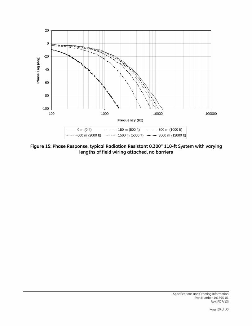
1. Unthreaded Length “AA” 5. Case, 300 Series SST, 3/8-24 UNF-2A or M10 thread
2. Case Length “BB” 6. 14.3 (9/16) Hex for 3/8-24 thread type 17.0 (0.67) Hex for M10 thread type
3. Total Length “CC”, ±7% 7. Miniature Male Coaxial Connector 7.23 (0.285) Outside Diameter Maximum
4. Tefzel® Coated Armor, 9.6 (0.377) diameter
Figure 22: 0.300” Radiation-resistant Proximity Probe, standard mount armored
27482, 3/8-24 UNF-2A threads
36446, M10x1 threads
43
7.62 [0.30]
11.1 [0.44]7.92 [0.31]
2
1
5
5.1 [0.20]
30.5 [1.20]
5.0 [0.20]
10.2 [0.40]
1. 11.1 (7/16) Hex 4. Miniature Male Coaxial Connector 7.23 (0.285) Outside Diameter Maximum
2. Case, 300 Series SST, 3/8-24 UNF-2A 5. Total Length “C”, ±7%
3. Coaxial Tefzel® cable 4.3 (0.17) Outside Diameter Maximum.
Figure 23: 27485, 0.300” Radiation-resistant Proximity Probe, Reverse Mount, 3/8-24 UNF-2A threads

Specifications and Ordering Information Part Number 141595-01
Rev. F(07/13)
Page 27 of 30
5
1
2
3 4
30.5 [1.20]
5.1 [0.20]
11.1 [.44]
10.7 [.42]
10.2 [0.40]
8.9 [0.35]
1. 7/16 Hex 4. Miniature Male Coaxial Connector 7.23 (0.285) Outside Diameter Maximum
2. Case, 300 Series SST, 3/8-24 UNF-2A 5. Total Length “C”, +25%, -10% 3. Coaxial Tefzel® cable 4.3 (0.17) Outside Diameter Maximum.
Figure 24: 19056, 0.420” Radiation-resistant Proximity Probe, Reverse Mount, 3/8-24 UNF-2A threads
6
1 42
5
3
1. Miniature Male Coaxial Connector 7.2 (0.285) Max. Diameter
4. Miniature Female Coaxial Connector 7.2 (0.285) Max. Diameter
2. Coaxial Tefzel® cable 4.3 (0.17) Outside Diameter Maximum. 5. 305 ± 152 (12.0 ± 6), 2 places
3. Tefzel® Coated Armor, 9.6 (0.377) diameter
6. 27490 .300 cable, Total Length “A”, ±7% 127502, .420 cable, Total Length = 12 feet (3.66 metres) +20%/-10%
Figure 25: Radiation-resistant Extension Cable
27490, 0.300 extension cable

Specifications and Ordering Information Part Number 141595-01
Rev. F(07/13)
Page 28 of 30
127502, 0.420 extension cable
1
63.5 [2.50]
81.3 [3.20]
50.8 [2.00]
61.2 [2.41]
50.8 [2.00]
2
1. Mounting Option “B” = “00” 2. 4.0 (0.158) diameter mounting thru holes,
qty 4
Figure 26: 330280 and 330281, Panel Mount Radiation-resistant XL Proximitor Sensor
1
3
2
70.8 [2.79]
31.7 [1.25]
1. Mounting Option “B” = “01” 2. 35mm DIN rail not included
2. 89.4 (3.52) Additional 3.0 (0.12) clearance required to remove DIN rail
Figure 27: 330280 and 330281, DIN Rail Mount Radiation-resistant XL Proximitor Sensor

Specifications and Ordering Information Part Number 141595-01
Rev. F(07/13)
Page 29 of 30
81(3.2)
(2.50)
(0.20)5.1
(2.41)61.2
(2.00)50.8
(3.20)81.3
(2.00)50.8
63.5
79.2 [3.12]50.8 [2.00]
50.8 [2.00]
50.8 [2.00]
60.5 [2.38]
Figure 28: Physical mounting characteristics showing interchangeability of the 3000 and XL Radiation Resistant Proximitor Sensors when 4-hole mounting
Notes: 1. All dimensions on figures are in millimeters (inches) unless otherwise noted. 2. Standard mount 0.300probes supplied with 17 mm or 9/16 inch lock nut. 3. Reverse mount probes not available with armor. 4. Letters inside quotation marks on figures refer to probe ordering options. 5. Stainless steel armor is supplied with Tefzel® outer jacket. 6. Coaxial cable contains Tefzel® dielectric and outer jacket.
Specifications and Ordering Information Part Number 141595-01
Rev. F(07/13)
Page 30 of 30
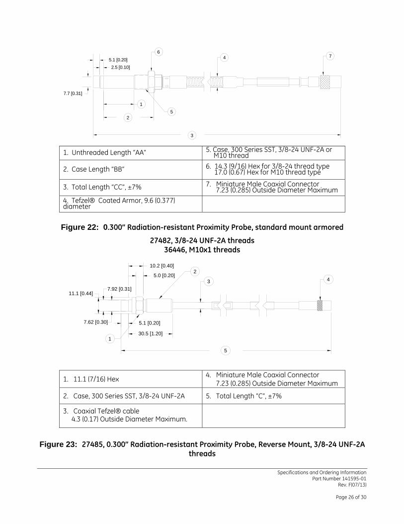
Summary- Radiation Testing Report Bently Nevada Inc. completed a series of tests to insure that the product will meet the specifications contained in this document. The information below outlines the details regarding the testing and irradiation. The customer can use this information to validate how the product is used and infer how the product could change with gamma-radiation exposures. Listed below are limitations and boundary conditions.
Important items about the testing: The Device Under Test (DUT) will have the largest parameter shift when the unit is powered up and being irradiated at the same
time. The gamma-radiation was from a Co60 source. A number of 16-inch-long rods were placed in a circular pattern around the DUT to
establish uniform radiation and exposure levels around the DUT. The length of the rods ensured that the top and bottom of the DUT were also being irradiated, albeit at a slightly lower level. The dosage rate is the sum effect of all of the rays intersecting at the DUT.
The product was not designed or tested:
to be a part of the control loop as the product design is for monitoring purposes only, for LOCA (loss of coolant accident), sometimes called LOC (loss of coolant), events, to withstand neutron radiation, or for spike or burst events.
Observation: As a note: A number of the units were tested and at no time did any of the units fail. The numbers of units tested at the higher radiation levels did not constitute a significant sample size to guarantee the product at these higher levels. Any observation or extrapolation of this data is not a guarantee of the product performance.
9 Mrads
ASF Change Voltage change @ linear range end
-7.61% -0.57 Vdc
ASF = Average Scale Factor
* Denotes a trademark of Bently Nevada, Inc., a wholly owned subsidiary of General Electric Company. Tefzel® is a registered trademark of E.I. du Pont de Nemours and Company.
© 2000 – 2013 Bently Nevada, Inc. All rights reserved.
Printed in USA. Uncontrolled when transmitted electronically.
1631 Bently Parkway South, Minden, Nevada USA 89423
Phone: 775.782.3611 Fax: 775.215.2873 www.ge-mcs.com/bently