Radiation Protection and Dose Optimisation - eanm.org€¦ · Radiation Protection and Dose...
124
Produced with the kind Support of Radiation Protection and Dose Optimisation A Technologist’s Guide Produced with the kind Support of Publications · Brochures
Transcript of Radiation Protection and Dose Optimisation - eanm.org€¦ · Radiation Protection and Dose...
Produced with the kind Support of
Radiation Protection and Dose Optimisation
A Technologist’s Guide
Produced with the kind Support of
Publications · Brochures
2
Editors Rep, Sebastijan (Ljubljana)Santos, Andrea (Lisbon)Testanera, Giorgio (Milan)
ContributorsAlessio, AdamBailey, ElizabethBrusa, AnnaBrzozowska, BeataChiesa, Carlode Nile, Maria Chiarade Palma, DiegoFahey, FredericFragoso Costa, PedroGilmore, DavidGoodkind, AlisonKriszan, Aron KrisztianLundholm, LovisaMira, MartaOuwens, Marga Rep, SebastijanRomero, ElizabethSantos, Ana IsabelWojcik, AndrzejZanette, Consuelo
EAN
M
3
Foreword . . . . . . . . . . . . . . . . . . . . . . . . . . . . . . . . . . . . . . . . . . . . . . . . . . . . . . . . . . . . . . . . . . . . . . . . . . . . . . . 4 Pedro Fragoso Costa
Introduction . . . . . . . . . . . . . . . . . . . . . . . . . . . . . . . . . . . . . . . . . . . . . . . . . . . . . . . . . . . . . . . . . . . . . . . . . . . . 5 Andrea Santos
Chapter 1 Interaction of Radiation with Matter . . . . . . . . . . . . . . . . . . . . . . . . . . . . . . . . . . . . 6 Aron Krisztian Krizsan
Chapter 2 Dosimetry Fundamentals . . . . . . . . . . . . . . . . . . . . . . . . . . . . . . . . . . . . . . . . . . . . . .15 Carlo Chiesa, Marta Mira, Maria Chiara de Nile, Consuelo Zanette, Anna Brusa
Chapter 3 International Basic Saftey Standards . . . . . . . . . . . . . . . . . . . . . . . . . . . . . . . . . .36 Pedro Fragoso Costa
Chapter 4 Radiobiology Principles . . . . . . . . . . . . . . . . . . . . . . . . . . . . . . . . . . . . . . . . . . . . . . . .46 Lovisa Lundholm, Beata Brzozowska, Andrzej Wojcik
Chapter 5 Radionuclide Dose Optimisation for Diagnostic Procedures (*) . . . . . . .56 Frederic H . Fahey, Alison B . Goodkind, David Gilmore
Chapter 6 CT Dose Optimisation (*) . . . . . . . . . . . . . . . . . . . . . . . . . . . . . . . . . . . . . . . . . . . . . . .71 Frederic Fahey, Elizabeth Romero, Adam Alessio
Chapter 7 Dose Optimisation for Radionuclide Therapy . . . . . . . . . . . . . . . . . . . . . . . . . .79 Marga Ouwens
Chapter 8 Paediatric Dose Optimisation . . . . . . . . . . . . . . . . . . . . . . . . . . . . . . . . . . . . . . . . . .93 Diego de Palma, Ana Isabel Santos
Chapter 9 Occupational Radiation Protection . . . . . . . . . . . . . . . . . . . . . . . . . . . . . . . . . . . .99 Sebastijan Rep
Chapter 10 Nuclear Medicine Department Design . . . . . . . . . . . . . . . . . . . . . . . . . . . . . . . 107 Elizabeth Bailey
*Articles were written with the kind support of and in cooperation with the
Table of Contents
4
ForewordPedro Fragoso Costa
Since its inception, more than 20 years ago, the EANM Technologist Committee (EANM-TC) has contributed greatly in encouraging professional development and scientific exchange amongst nuclear medicine tech-nologists (NMTs) . The Technologist’s Guide series is one of the most successful EANM-TC endeavours, with an ongoing yearly release since 2004 . These brochures have become not only a valuable tool in the clinical work-place but also a reference for educational purposes .
After a long series of clinical guides, it was decided to shift to a more technical, but equally important field: Radiation Protection and Dose Reduction . The major rationale for this choice was the fact that NMTs, radiogra-phers and all medical radiation professionals will have radiation protection concerns, in-dependently of the specific set-up (i .e . nu-clear cardiology, PET/CT, conventional NM or therapeutic NM) . Furthermore, the newly defined EU Euratom Directive [1] is to take ef-fect in 2018; therefore investing in education and training in the field of radioprotection at this moment is timely and purposeful . Fi-nally, this publication presents an excellent opportunity to become acquainted with the
most modern internal and external dosime-try calculation methods and radiological risk assessment and to gain an insight into the European legal requirements in respect of protection against ionising radiation .
This brochure is the product of a multidis-ciplinary team of health radiation experts, to whom I am extremely grateful . I would like to thank the EANM Physics Committee, SNMMI-TS (Society of Nuclear Medicine and Molecular Imaging Technologist Section) and ANZSNM (Australian and New Zealand Society of Nuclear Medicine) for helping to ensure the outstanding quality of this book . I am very much indebted to Andrea Santos, Sebastijan Rep and Giorgio Testanera for their dedication in reviewing and editing this guide in record time . Finally, thanks are due to Rick Mills and Sonja Niederkofler for their support in language editing and logis-tics, the EANM Board, the EANM Technologist Committee and all of those involved in the Technologist Guide project .
Pedro Fragoso CostaChair, EANM Technologist Committee
Reference1 . European Council Directive 2013/59/Euratom on basic safety standards for protection against the dangers arising from
exposure to ionising radiation and repealing Directives 89/618/Euratom, 90/ 641/Euratom, 96/29/Euratom, 97/43/Euratom and 2003/122/ Euratom . Official Journal of the European Union; 2014;L13:1-17 .

EAN
M
5
IntroductionAndrea Santos
Since the beginning of the 20th century, ionis-ing radiation has been employed in medicine for both diagnostic and therapeutic purpos-es . The belief that radioactive sources could heal many different diseases led to a rapid increase in the usage of radioactive material; in conjunction with the lack of knowledge of the biological effects of radiation, this result-ed in many accidents and numerous patholo-gies in both patients and operators .
Ionising radiation procedures for medical purposes have been invaluable in improving patient care . Accordingly, the use of radiation in medicine has continued to increase over the years, accompanied by improvements in safety standards . Nuclear medicine (NM) has been deeply involved in this process . Both applications – diagnostic and therapeutic – showed great initial potential and import-ant advances have repeatedly been achieved over the intervening decades .
The development of NM has been accompa-nied by great responsibility, since the safety of both the professional and the patient depends on the correct use of radiation . The professional should not be harmed by the radiation need-ed to perform each procedure and the patient should only be exposed to radiation after the benefit/risk ratio has been considered .
This year’s Technologist’s Guide aims to give an overview on the principles of radiation protec-tion and to provide the professional with the knowledge required in order to act in accor-
dance with these principles . A further intention is to set out the principles of dose optimisation . There is a consensus that all NM procedures must be justified; furthermore, the radiation used in each procedure must be carefully calcu-lated and based on rigorous quality standards .
This book starts with overviews on the inter-action of radiation with matter and the fun-damentals of dosimetry . It continues by cov-ering the international basic safety standards and radiobiology principles . The basic con-cepts of dose optimisation for diagnostic and therapeutic procedures involving the use of radionuclides are explained, and an individual chapter focuses specifically on dose optimis-ation in the paediatric population . After this, aspects of occupational radiation protection are covered, and finally the design of an NM department is discussed, keeping in mind the particularities that need to be considered in order to ensure compliance with radiation protection standards . Each chapter includes a description of the specific role of NMTs as main actors in procedures who also bear re-sponsibility for the application of radiation protection in daily practice .
In closing, I would like to express my grati-tude to all the authors, co-editors and profes-sionals who have contributed their time and expertise to help ensure the realisation of this project: Radiation Protection and Dose Optimi-sation – A Technologist’s Guide.
Andrea Santos
6
Chapter 1: Interaction of Radiation with MatterAron Krisztian Krizsan
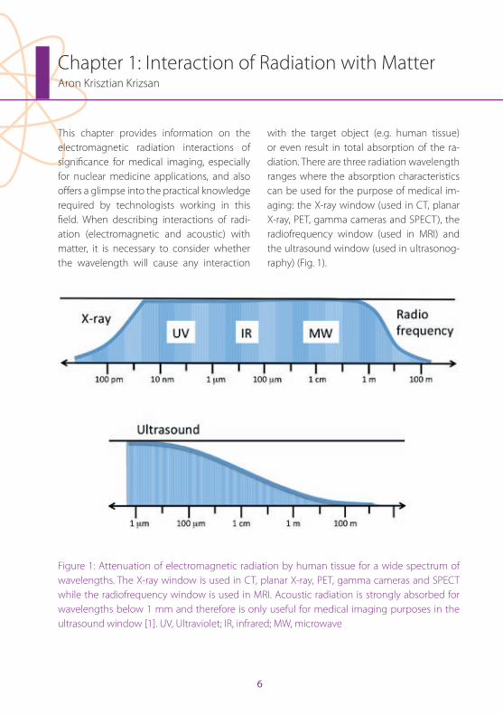
This chapter provides information on the electromagnetic radiation interactions of significance for medical imaging, especially for nuclear medicine applications, and also offers a glimpse into the practical knowledge required by technologists working in this field . When describing interactions of radi-ation (electromagnetic and acoustic) with matter, it is necessary to consider whether the wavelength will cause any interaction
with the target object (e .g . human tissue) or even result in total absorption of the ra-diation . There are three radiation wavelength ranges where the absorption characteristics can be used for the purpose of medical im-aging: the X-ray window (used in CT, planar X-ray, PET, gamma cameras and SPECT), the radiofrequency window (used in MRI) and the ultrasound window (used in ultrasonog-raphy) (Fig . 1) .
Figure 1: Attenuation of electromagnetic radiation by human tissue for a wide spectrum of wavelengths . The X-ray window is used in CT, planar X-ray, PET, gamma cameras and SPECT while the radiofrequency window is used in MRI . Acoustic radiation is strongly absorbed for wavelengths below 1 mm and therefore is only useful for medical imaging purposes in the ultrasound window [1] . UV, Ultraviolet; IR, infrared; MW, microwave
EAN
M
7
Chapter 1: Interaction of Radiation with Matter
Ionisation, excitation and bremsstrahlung Let us consider a radiation interaction as a single system . The comparison of the system before and after the interaction reveals that some quantities remain the same following the interaction . These quantities are often referred to as being conserved in the interac-tion . Such conserved quantities include total energy, momentum and electric charge . With respect to ionisation, a distinction is drawn between directly ionising particles (charged particles) and indirectly ionising particles (uncharged particles) . Directly ionising par-ticles comprise the alpha particles (helium nuclei), beta particles (electrons), protons and any other nuclei . Indirectly ionising parti-cles are the photons (in the adequate energy range) and neutrons . While there is a definite difference between the classical and quan-tum electrodynamic explanations of interac-tions between particles, within this chapter the classical model is applicable since the focus is on which particles will survive, where they go and what happens to their energy . On the atomic scale it is practical to use the energy units of electron volt (eV), which is by definition the amount of energy that an electron gains when it travels through a po-tential difference of 1 volt (numerically 1 eV = 1 .6×10-19 J) .
An atom becomes ionised when it ejects at least one electron . Below an energy limit of 13 .6 eV, radiation is not able to induce ion-isation; therefore, radiation with an energy
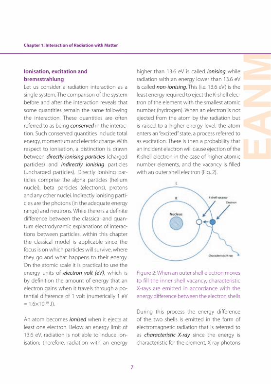
higher than 13 .6 eV is called ionising while radiation with an energy lower than 13 .6 eV is called non-ionising . This (i .e . 13 .6 eV) is the least energy required to eject the K-shell elec-tron of the element with the smallest atomic number (hydrogen) . When an electron is not ejected from the atom by the radiation but is raised to a higher energy level, the atom enters an “excited” state, a process referred to as excitation . There is then a probability that an incident electron will cause ejection of the K-shell electron in the case of higher atomic number elements, and the vacancy is filled with an outer shell electron (Fig . 2) .
Figure 2: When an outer shell electron moves to fill the inner shell vacancy, characteristic X-rays are emitted in accordance with the energy difference between the electron shells
During this process the energy difference of the two shells is emitted in the form of electromagnetic radiation that is referred to as characteristic X-ray since the energy is characteristic for the element, X-ray photons
8
of different energy being emitted according to the characteristics of the electron shells of the atom . The incident electrons may only be repelled by the nucleus, and while they are continuously accelerated in the electric field of the nucleus, electromagnetic radiation is emitted in the X-ray spectrum . This is the so-called bremsstrahlung process . The clas-sical electromagnetic explanation derives from the fact that an electric charge moving with constant velocity would not emit elec-tromagnetic radiation, whereas in the event
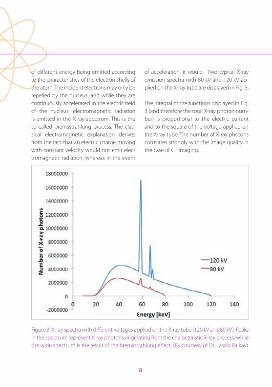
of acceleration, it would . Two typical X-ray emission spectra with 80 kV and 120 kV ap-plied on the X-ray tube are displayed in Fig . 3 .
The integral of the functions displayed in Fig . 3 (and therefore the total X-ray photon num-ber) is proportional to the electric current and to the square of the voltage applied on the X-ray tube . The number of X-ray photons correlates strongly with the image quality in the case of CT imaging .
Figure 3: X-ray spectra with different voltages applied on the X-ray tube (120 kV and 80 kV) . Peaks in the spectrum represent X-ray photons originating from the characteristic X-ray process, while the wide spectrum is the result of the bremsstrahlung effect . (By courtesy of Dr . Laszlo Balkay)
Chapter 1: Interaction of Radiation with Matter
EAN
M
9
Radioactive decay and characteristics of radiationThe nuclide of an atom can be unstable in the presence of a certain ratio of protons and neutrons, leading to an emission pro-cess called radioactive decay . Radioactive decay has three major forms: alpha (α), beta (β) and gamma (γ) . In the case of α-emission, expulsion of a helium nucleus from the atom occurs, that consists of two neutrons and two protons . Alpha decay occurs primarily among heavy elements that are of little in-terest in nuclear medicine . Beta decay can occur in two forms: β- and β+ . During β- decay a neutron in the nucleus is converted into a proton and an electron, followed by ejec-tion of the electron together with a neutrino (ν) . The electron in this case is referred to as a β- particle while the neutrino is a “particle” that has no mass or electric charge . In the case of β+ decay, a proton in the nucleus is transformed into a neutron and the so-called positron, which is the anti-particle of the electron . This process is followed by emis-sion of the positron together with a neutri-no . We sometimes refer to α- and β-particles as charged particles because they carry an electric charge . Gamma emission can occur in several ways . The atom may have three different states: the most stable arrangement of the nucleons, called the ground state; a very unstable state with only a transient exis-tence, which is termed the excited state; and a further unstable state that, however, has a life-time longer than 10-12 s and is called the metastable state [2] . The nuclear transitions
between different nucleon arrangements in-volve discrete and exact amounts of energy and therefore can result (in the direction of the ground state) in emission of particles or γ-rays . The energy difference between the states determines the γ-ray energy . Even a β-
emission with a metastable daughter nucle-us can result in a final γ-ray emission [2] . An-other route for γ-photon emission is through a β+ decay, when the ejected positron loses kinetic energy by inelastic interactions with atomic electrons . Then, a temporary particle called the positronium is formed with a final electron . This is followed by the annihilation process, while the mass of the positron and the electron are converted into two 511-keV γ-photons, which are emitted simultaneously at about 180° with respect to each other [3] .
Interaction of γ-rays and X-rays with matterAs described in the preceding sections, the dif-ference between X-rays and γ-rays derive from their origin and are not necessarily observable in their energy . Both are forms of electromag-netic radiation and have a certain probability of passing through different processes based on their energy . The energy of X-rays and γ-rays in nuclear medicine applications regu-larly causes three kinds of interactions: photo-electric absorption, Compton scatter and pair production . The last-mentioned occurs when a photon interacts with the electric field of a charged particle and the photon disappears while its energy is used to create a positive–negative electron pair (an electron and a
10
positron) . Because both the positron and the electron have a rest mass equivalent to 0 .511 MeV, the minimum photon energy necessary for pair production is 1 .022 MeV . In nuclear medicine applications this photon energy is rarely used, and therefore we focus below on the other two interactions .
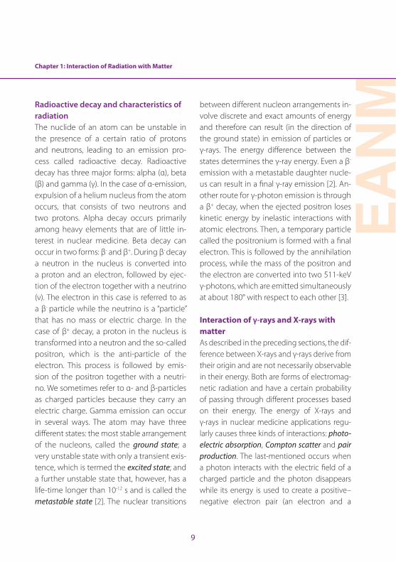
During the photoelectric effect or photoelec-tric absorption (PEA), the target atom absorbs the total energy of the incident photon . While the photon disappears, this energy is used to eject one of the orbital electrons, which is therefore called a photoelectron. The kinetic energy of the photoelectron is equal to the difference between the incident photon en-ergy and the binding energy of the electron shell from which it was ejected [2] . The kinetic energy of the photoelectron is deposited in the near site of the interaction during exci-tation and ionisation processes . Photoelec-tron ejection from the innermost electron shell is most probable if sufficient incident
photon energy is available . A schematic rep-resentation of PEA is shown in Fig . 4 .
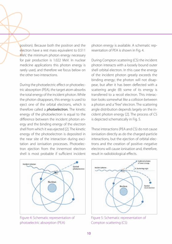
During Compton scattering (CS) the incident photon interacts with a loosely bound outer shell orbital electron . In this case the energy of the incident photon greatly exceeds the binding energy; the photon will not disap-pear, but after it has been deflected with a scattering angle (θ) some of its energy is transferred to a recoil electron . This interac-tion looks somewhat like a collision between a photon and a “free” electron . The scattering angle distribution depends largely on the in-cident photon energy [2] . The process of CS is depicted schematically in Fig . 5 .
These interactions (PEA and CS) do not cause ionisation directly as do the charged-particle interactions, but the ejection of orbital elec-trons and the creation of positive–negative electrons will cause ionisation and, therefore, result in radiobiological effects .
Figure 4: Schematic representation of photoelectric absorption (PEA)
Figure 5: Schematic representation of Compton scattering (CS)
Chapter 1: Interaction of Radiation with Matter
EAN
M
11
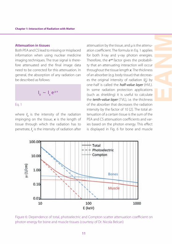
Attenuation in tissues Both PEA and CS lead to missing or misplaced information when using nuclear medicine imaging techniques . The true signal is there-fore attenuated and the final image data need to be corrected for this attenuation . In general, the absorption of any radiation can be described as follows:
I0 ~ Ix eμ x
Eq . 1
where I0 is the intensity of the radiation impinging on the tissue, x is the length of tissue through which the radiation has to penetrate, Ix is the intensity of radiation after
attenuation by the tissue, and µ is the attenu-ation coefficient . The formula in Eq . 1 applies for both X-ray and γ-ray photon energies . Therefore, the eµx factor gives the probabili-ty that an attenuating interaction will occur throughout the tissue length x . The thickness of an absorber (e .g . body tissue) that decreas-es the original intensity of radiation (I0) by one-half is called the half-value layer (HVL) . In some radiation protection applications (such as shielding) it is useful to calculate the tenth-value layer (TVL), i .e . the thickness of the absorber that decreases the radiation intensity by the factor of 10 [2] . The total at-tenuation of a certain tissue is the sum of the PEA and CS attenuation coefficients and var-ies based on the photon energy . This effect is displayed in Fig . 6 for bone and muscle
Figure 6: Dependence of total, photoelectric and Compton scatter attenuation coefficient on photon energy for bone and muscle tissues (courtesy of Dr . Nicola Belcari)
12
density tissues . It can be observed that PEA becomes less dominant at around 50 keV and that most of the interactions are CS for higher photon energies .
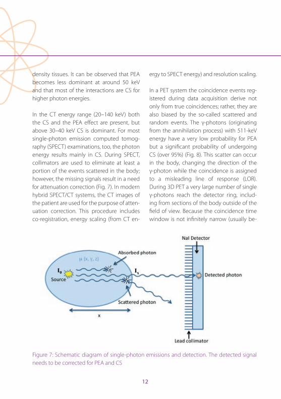
In the CT energy range (20–140 keV) both the CS and the PEA effect are present, but above 30–40 keV CS is dominant . For most single-photon emission computed tomog-raphy (SPECT) examinations, too, the photon energy results mainly in CS . During SPECT, collimators are used to eliminate at least a portion of the events scattered in the body; however, the missing signals result in a need for attenuation correction (Fig . 7) . In modern hybrid SPECT/CT systems, the CT images of the patient are used for the purpose of atten-uation correction . This procedure includes co-registration, energy scaling (from CT en-
ergy to SPECT energy) and resolution scaling .
In a PET system the coincidence events reg-istered during data acquisition derive not only from true coincidences; rather, they are also biased by the so-called scattered and random events . The γ-photons (originating from the annihilation process) with 511-keV energy have a very low probability for PEA but a significant probability of undergoing CS (over 95%) (Fig . 8) . This scatter can occur in the body, changing the direction of the γ-photon while the coincidence is assigned to a misleading line of response (LOR) . During 3D PET a very large number of single γ-photons reach the detector ring, includ-ing from sections of the body outside of the field of view . Because the coincidence time window is not infinitely narrow (usually be-
Figure 7: Schematic diagram of single-photon emissions and detection . The detected signal needs to be corrected for PEA and CS
Chapter 1: Interaction of Radiation with Matter
EAN
M
13
tween 5 and 10 ns), there is a high likelihood that two single photons from two different annihilation events will arrive during the giv-en coincidence time window, resulting in a random coincidence event . These random events then contribute to the noise level of the final images . The final detected count rate will consist of the count rates mentioned above as:
M ~ Atten × T + S + R
Eq . 2 .
where M is the measured count rate, Atten is the attenuation effect, T is the true count rate, S is the scatter count rate and R is the random count rate . Random events, atten-uation and CS will result in a distorted PET
signal and therefore have a great impact on the image data . Because of the geome-try of the patient, these interactions cause severe attenuation that is more prominent in the inner parts of the body and lower at the surface . As discussed above, the results of these interactions are the removal of primary photons from a given LOR and the potential detection of scattered photons in a different LOR . Thus, attenuation and scatter are side effects of the same physical process . Cor-rections are necessary and include removal of the estimated scatter fraction from the LORs . Moreover, it is necessary subsequently to correct each LOR for the fraction of events missing from that LOR .
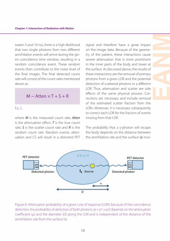
The probability that a γ-photon will escape the body depends on the distance between the annihilation site and the surface (x) mul-
Figure 8: Attenuation probability of a given Line of response (LOR): because of the coincidence detection, the probability of detection of both photons (p = p1 × p2) depends on the attenuation coefficient (µ) and the diameter (D) along the LOR and is independent of the distance of the annihilation site from the surface (x)
14
tiplied by the attenuation coefficient of the tissue (µ) . The probability of detecting both photons is the product of the individual probabilities that one of the photons will es-cape the body [4] . Therefore, only the diame-ter (D) of the patient along the LOR contrib-utes to the equation of this probability (Eq . 3), regardless of the distance of the annihilation site from the surface:
p = p2× p1 = e-μ(D-x) × e -μx = e-μD
Eq . 3
Attenuation of the signal from a given LOR can be measured with different algorithms from CT or MR images of the same patient . This so-called µ-map is generated using a bilinear scaling method in the case of CT im-ages . For MRI, segmentation algorithms are routinely employed, using a Dixon sequence . Besides attenuation correction, scatter and random corrections are performed on the
raw data of PET images . It must be empha-sised that all corrections will contribute to the overall noise characteristics of the recon-structed images, while the average image pixel values will be unbiased and will refer more closely to the true signal .
Acknowledgements. The author would like to express his gratitude to Dr . Laszlo Balkay for his advice and thoughtful conversations during the writing process, and to Dr . Nicola Belcari for his help in the figure presentations .
References
1 . Ernst R, Bodenhausen G, Wokaun A . Principles of nu-clear magnetic resonance in one and two dimensions . Oxford: Oxford Science Publications; 1990 .
2 . Cherry SR, Sorenson JA, Phelps ME . Physics in nuclear medicine . 3rd ed . Philadelphia: Saunders; 2003 .
3 . Hendee WR, Ritenour ER . Medical imaging physics . 4th ed . New York: Wiley-Liss; 2002 .
4 . Cherry SR, Dahlbom M . PET: physics, instrumentation and scanners . In: Phelps ME, ed . PET, molecular imaging and its biological applications . Berlin Heidelberg New York: Springer; 2004 .
EAN
M
15
Chapter 2: Dosimetry Fundamentals for Technologists: Dosimetry in Radionuclide TherapyCarlo Chiesa, Marta Mira, Maria Chiara De Nile, Consuelo Zanette and Anna Brusa
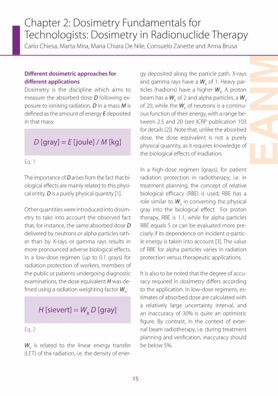
Different dosimetric approaches for different applicationsDosimetry is the discipline which aims to measure the absorbed dose D following ex-posure to ionising radiation . D in a mass M is defined as the amount of energy E deposited in that mass:
D [gray] = E [joule] / M [kg]
Eq . 1
The importance of D arises from the fact that bi-ological effects are mainly related to this physi-cal entity . D is a purely physical quantity [1] .
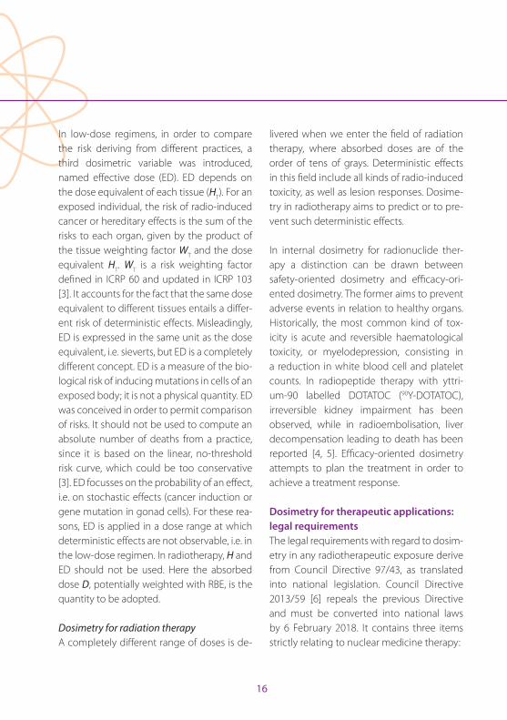
Other quantities were introduced into dosim-etry to take into account the observed fact that, for instance, the same absorbed dose D delivered by neutrons or alpha particles rath-er than by X-rays or gamma rays results in more pronounced adverse biological effects . In a low-dose regimen (up to 0 .1 grays) for radiation protection of workers, members of the public or patients undergoing diagnostic examinations, the dose equivalent H was de-fined using a radiation weighting factor WR:
H [sievert] = WR D [gray]
Eq . 2
WR is related to the linear energy transfer (LET) of the radiation, i .e . the density of ener-
gy deposited along the particle path . X-rays and gamma rays have a WR of 1 . Heavy par-ticles (hadrons) have a higher WR . A proton beam has a WR of 2 and alpha particles, a WR of 20, while the WR of neutrons is a continu-ous function of their energy, with a range be-tween 2 .5 and 20 (see ICRP publication 103 for details [2]) . Note that, unlike the absorbed dose, the dose equivalent is not a purely physical quantity, as it requires knowledge of the biological effects of irradiation .
In a high-dose regimen (grays), for patient radiation protection in radiotherapy, i .e . in treatment planning, the concept of relative biological efficacy (RBE) is used; RBE has a role similar to WR in converting the physical gray into the biological effect . For proton therapy, RBE is 1 .1, while for alpha particles RBE equals 5 or can be evaluated more pre-cisely if its dependence on incident α-partic-le energy is taken into account [3] . The value of RBE for alpha particles varies in radiation protection versus therapeutic applications .
It is also to be noted that the degree of accu-racy required in dosimetry differs according to the application . In low-dose regimens, es-timates of absorbed dose are calculated with a relatively large uncertainty interval, and an inaccuracy of 30% is quite an optimistic figure . By contrast, in the context of exter-nal beam radiotherapy, i .e . during treatment planning and verification, inaccuracy should be below 5% .
16
In low-dose regimens, in order to compare the risk deriving from different practices, a third dosimetric variable was introduced, named effective dose (ED) . ED depends on the dose equivalent of each tissue (HT) . For an exposed individual, the risk of radio-induced cancer or hereditary effects is the sum of the risks to each organ, given by the product of the tissue weighting factor WT and the dose equivalent HT . WT is a risk weighting factor defined in ICRP 60 and updated in ICRP 103 [3] . It accounts for the fact that the same dose equivalent to different tissues entails a differ-ent risk of deterministic effects . Misleadingly, ED is expressed in the same unit as the dose equivalent, i .e . sieverts, but ED is a completely different concept . ED is a measure of the bio-logical risk of inducing mutations in cells of an exposed body; it is not a physical quantity . ED was conceived in order to permit comparison of risks . It should not be used to compute an absolute number of deaths from a practice, since it is based on the linear, no-threshold risk curve, which could be too conservative [3] . ED focusses on the probability of an effect, i .e . on stochastic effects (cancer induction or gene mutation in gonad cells) . For these rea-sons, ED is applied in a dose range at which deterministic effects are not observable, i .e . in the low-dose regimen . In radiotherapy, H and ED should not be used . Here the absorbed dose D, potentially weighted with RBE, is the quantity to be adopted .
Dosimetry for radiation therapyA completely different range of doses is de-
livered when we enter the field of radiation therapy, where absorbed doses are of the order of tens of grays . Deterministic effects in this field include all kinds of radio-induced toxicity, as well as lesion responses . Dosime-try in radiotherapy aims to predict or to pre-vent such deterministic effects .
In internal dosimetry for radionuclide ther-apy a distinction can be drawn between safety-oriented dosimetry and efficacy-ori-ented dosimetry . The former aims to prevent adverse events in relation to healthy organs . Historically, the most common kind of tox-icity is acute and reversible haematological toxicity, or myelodepression, consisting in a reduction in white blood cell and platelet counts . In radiopeptide therapy with yttri-um-90 labelled DOTATOC (90Y-DOTATOC), irreversible kidney impairment has been observed, while in radioembolisation, liver decompensation leading to death has been reported [4, 5] . Efficacy-oriented dosimetry attempts to plan the treatment in order to achieve a treatment response .
Dosimetry for therapeutic applications: legal requirementsThe legal requirements with regard to dosim-etry in any radiotherapeutic exposure derive from Council Directive 97/43, as translated into national legislation . Council Directive 2013/59 [6] repeals the previous Directive and must be converted into national laws by 6 February 2018 . It contains three items strictly relating to nuclear medicine therapy:
Chapter 2: Dosimetry Fundamentals for Technologists: Dosimetry in Radionuclide Therapy
EAN
M
17
1 . Definition 81: “radiotherapeutic” means pertaining to radiotherapy, including nu-clear medicine for therapeutic purposes.
2 . Article 56 (the Optimisation principle ap-plied to radiotherapy): For all medical ex-posure of patients for radiotherapeutic purposes, exposures of target volumes shall be individually planned and their delivery appropriately verified taking into account that doses to non-target volumes and tissues shall be as low as reasonably achievable and consistent with the intend-ed radiotherapeutic purpose of the expo-sure.
3 . Article 57: Responsibilities:
1. Member States shall ensure that: (a) any medical exposure takes place under the
clinical responsibility of a practitioner; (b) the practitioner, the medical physics expert
and those entitled to carry out practical as-pects of medical radiological procedures are involved, as specified by Member States, in the optimisation process.
It is therefore clearly stated that nuclear med-icine treatments: • cannot be considered different from
external beam radiation therapy (EBRT);
• should be planned (and verified) individually, through dosimetry of target and non-target volumes;
• should be optimised, i .e . delivered with reasonably low dosage, but not so low
as to negate the therapeutic effect of the treatment .
Article 57, a real novelty, remarks on the legal responsibility for ensuring compliance with the optimisation principle .
For a number of historical and practical reasons, the activity to be administered in radionuclide therapy is at present chosen using empirical or raw dosimetric methods . Pre-treatment dosimetry (treatment plan-ning) is only seldom applied . The same can be said for peri-treatment dosimetry (verifi-cation) .
Note that radionuclide therapy is often de-livered in a series of administrations . This is the case in treatments of thyroid cancer with radioiodine and of neuroendocrine tumours with radiolabelled somatostatin analogues (radiopeptides) or iodine-131 metaiodoben-zylguanidine (131I-mIBG) . Verification dosim-etry performed during the first administra-tion can be used as treatment planning for the subsequent administrations, with the limitation that a variation in tumour uptake following one administration (therapeutic response) will also alter the normal organ uptake .
Dosimetry methodsAlthough “dosimetry” literally means “mea-surement of the dose”, internal dosimetry is always a rather indirect dose calculation . For this purpose, three main methods have been developed:
18
1 . The Medical Internal Radiation Dose (MIRD) schema [7–10]
2 . Convolution methods (MIRD pamphlet 17 [8])3 . Patient-specific Monte Carlo-based meth-
ods
These methods are characterised by in-creasing levels of accuracy and complexity . However, their basic needs are the same: quantitative evaluations of the activity content in metabolically active tissues or perfused volumes and of the variations in this activity over time . This represents a pro-found difference from EBRT dosimetry . The dose distribution from an accelerator beam or from a sealed source (brachytherapy) can be simulated, using as input data a CT scan of the patient and the beam or the source characteristic . In radionuclide therapy, the activity biodistribution and its physiologi-cal variation over time must be studied by sequential patient data collection . This may include thyroid uptake measurements, im-ages, blood sampling, whole body counts, and collection of urine samples, depending on the injected radiopharmaceutical and the aim of dosimetry . The frequency and time framework of data collection depend on the nature of the treated disease and on the clearance of the used agent . The conse-quence may be a non-negligible workload for both the patient and the division . This argument, often used in the past against in-ternal dosimetry, is weak when one consid-ers that a complete EBRT treatment requires daily irradiation for weeks .
The Medical Internal Radiation Dose (MIRD) schema for organ dosimetryThe simplest dosimetry method was pro-posed by the MIRD Committee [7–10] . De-spite its apparently complicated formalism, we try here to develop its main concepts in a non-rigorous but didactic way, following a paper by Mike Stabin [11] . We also use the most popular and historical nomenclature (MIRD Primer 1991) [7], though a new, official, but still unused nomenclature was published in MIRD pamphlet 21 (2009) [8] .
The schema was originally conceived to eval-uate mean absorbed dose at organ level and was based on the classification of an organ as source or target . A source organ is perfused or displays uptake of the radioactive agent, while target organs passively receive irradi-ation from source organs . Within this frame-work, it is important to distinguish between two kinds of radiation:
• Non-penetrating radiation, which is incapable of going beyond the borders of the source organ to reach other organs . Such radiation is typically charged particles (beta particles, positrons, alpha particles) .
• Penetrating radiation, capable of transferring energy from a source to a target organ . Such radiation is typically gamma rays or X-rays .
Two important points should be noted . First, the MIRD schema has been extended from the organ level down to the cellular
Chapter 2: Dosimetry Fundamentals for Technologists: Dosimetry in Radionuclide Therapy
EAN
M
19
level, where the source region may be the cell membrane, and the target region, the nucleus . In this case, the classification of charged particles as “non-penetrating radi-ation” should be revised, since any of these particles can reach the cell nucleus from the membrane . Second, remaining at the or-gan level, consider, for instance, 131I thyroid uptake . Here, 94% of the absorbed dose is attributable to beta rays and only 6% to 364-keV photons . For liver uptake of the same isotope, the contribution of gamma rays increases to 25% . The relative amount of absorbed dose from gamma rays reaches a
maximum of 42% if we consider the largest source for the standard 73-kg male, i .e . its whole body, uniformly filled by radioiodine . If, on the other hand, 177Lu is considered, the low photon abundance means that 96% of the liver dose is due to beta rays, and only 4% to gamma rays . Therefore, for beta-gam-ma emitters in clinical use, the highest ab-sorbed dose is delivered to source organs by beta particles . This fact is highly relevant in understanding the implications of the MIRD schema in the following different situations of increasing complexity .
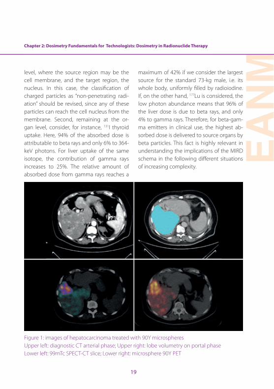
Figure 1: images of hepatocarcinoma treated with 90Y microspheres Upper left: diagnostic CT arterial phase; Upper right: lobe volumetry on portal phase Lower left: 99mTc SPECT-CT slice; Lower right: microsphere 90Y PET

20
Consider as an example an organ subject to self-irradiation only from non-penetrating radiation: a liver lobe injected with 90Y mi-crospheres (Fig . 1) . Such devices are perma-nently trapped in capillaries and release their beta energy in tissue until complete decay has occurred . At each time instant, the lobe dose rate dD/dt (Gy/min) is proportional to the activity burden . Let us introduce the pro-portionality constant, called S:
dD/dt = S A(t)
Eq . 3
The differential absorbed dose to the organ during a small interval of time dt, during which the activity can be considered con-stant, is given by the dose rate times dt:
dD = S A(t) dt
Eq . 4
The total absorbed dose is given by the sum of all the time intervals, from the zero time (administration) to infinite time . A sum of dif-ferential terms is mathematically performed by an integral:
D = S ∫ A(t) dt
Eq . 5
Since 90Y microspheres are permanently trapped, the time-activity curve (TACT curve) in the lobe is given by the mono-exponential decay curve of the administered activity A0 of 90Y, with a half-life T1/2 = 64 .2 h and a decay constant λ = ln2 / T1/2:
A(t) = A0 exp(- λ t)
Eq . 6
The integral in eq . (5) can be easily solved:
∫ A(t) dt = ∫ A0 exp(- λ t) = A0 ∫ exp(- λ t) = A0 / λ
Eq . 7
Finally the absorbed dose is given by:
D = S A0 / λ
Eq . 8
The integral in eq . (7) has a simple physical meaning . The activity A(t) is by definition the number of decays per second . A(t) multiplied by the time dt in eq . (4) gives the number of decays during the interval dt . The integral [eq . (7)] is therefore the total number of de-cays (NDs) of 90Y nuclides in the liver lobe, from the administration to infinite time:
Chapter 2: Dosimetry Fundamentals for Technologists: Dosimetry in Radionuclide Therapy
EAN
M
21
∫ A(t) dt = NDs
Eq . 9
Then
D = S × NDs
Eq . 10
It is no surprise that the absorbed dose is proportional to the number of decays in the organ .
The problem now is the value of the parame-ter S . This, too, can be easily calculated (in this first easy case) . Solving eq . (10) for S, we have:
S = D / NDs
Eq . 11
S is the absorbed dose per one decay . From the definition of absorbed dose, it can be in-ferred that this quantity is given by the mean beta energy (933 keV) emitted by 90Y divided by the perfused region mass M:
S = 933 keV / M
Eq . 12
We now have all the parameters needed to compute the absorbed dose to the injected portion of liver with mass M liver from 90Y mi-crospheres:
D = 933 keV / M × A0 / λ
Eq . 13
This can be approximated, compacting the physical constant into a formula:
D [Gy] = 50 / M [kg] × A0 [GBq]
Eq . 14
The multiplication symbol “×” was intention-ally inserted . It refers to the basic splitting of the MIRD dose calculation into two factors (eq . 10) . The absorbed dose in eq . (13) is the product of two independent terms: the first one (50/M), i .e . the S term, accounts for the isotope emitted energy and organ geometry (mass), while the second in this case is simply the injected activity .
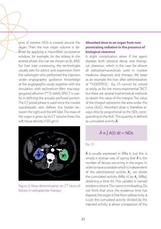
Note that for an accurate dosimetric estima-tion, the organ or the perfused portion mass M should be carefully evaluated (Fig . 1 upper left, Fig . 2) . This is usually done by contouring the organ under study or its portions on CT slices . This necessary step is performed by technologists in a number of centres . For a more accurate determination, a first raw vol-
22
ume of interest (VOI) is created around the organ . Then the true organ volume is de-fined by applying a Hounsfield acceptance window; for example, for the kidney in the arterial phase, this can be chosen as [0, 400] . For liver lobe contouring, the technologist usually asks for advice and supervision from the radiologist who performed the injection under angiographic guidance . Knowledge of the angiographic study together with the simulation with technetium-99m macroag-gregated albumin (99mTc-MAA) SPECT is use-ful in defining the actually perfused portion . The CT portal phase is used since the medial suprahepatic vein defines the border be-tween the right and the left lobe . The mass of the organ is given by its CT volume times the soft tissue density (1 .03 g/cc) .
Figure 2: Mass determination on CT slices of kidney in radiopeptide therapy
Absorbed dose to an organ from non-penetrating radiation in the presence of biological clearanceA slight complication arises if the agent displays both physical decay and biologi-cal clearance, which is the case for almost all radiopharmaceuticals used in nuclear medicine diagnosis and therapy . We keep as an example the liver after administration of 90Y-DOTATOC . Eq . (7) cannot be solved as easily as for the mono-exponential TACT, but there are several mathematical methods to obtain the value of the integral . The value of the integral represents the area under the curve (AUC) . Absorbed dose is therefore al-ways directly proportional to the NDs, corre-sponding to the AUC . This quantity is defined as cumulated activity Ã:
à = ∫ A(t) dt = NDs
Eq . 15
à is usually expressed in MBq h, but this is simply a strange way of saying that à is the number of decays occurring in the organ . In order to have a variable which is independent of the administered activity A0, we divide the cumulated activity (MBq h) by A0 (MBq), obtaining a time (h) . This variable is named residence time τ . This name is misleading . Do not think that once the residence time has elapsed, the organ is free from radioactivity . τ is just the cumulated activity divided by the injected activity . τ allows comparison of the
Chapter 2: Dosimetry Fundamentals for Technologists: Dosimetry in Radionuclide Therapy
EAN
M
23
absorbed dose per unit activity . For any given isotope, the higher is τ, the higher will be the absorbed dose per unit activity .
τ = Ã / A0
Eq . 16
The basic MIRD equation is:
D = S × Ã
Eq . 17
The simplicity of the MIRD methodology is evident in this product . For 90Y only, S is giv-en by eq . (12) . The second term depends on the liver clearance, i .e . on organ biokinetics, which is an individual characteristic . Other, probably more familiar examples of biokinet-ics in diagnostics are the kidney TACT curves in a dynamic study .
Here we confront the key point concerning the need for individualised dosimetry: Every individual shows his or her own clearance curve (TACT) in his or her organs and for each injected radiopharmaceutical. This implies that in order to achieve complete dosimetry, i .e . optimised radionuclide therapy, the TACT of each source organ has to be determined in each individual patient . This is usually done with a sequence of scans . Biokinetics may change even for the same patient after a ther-
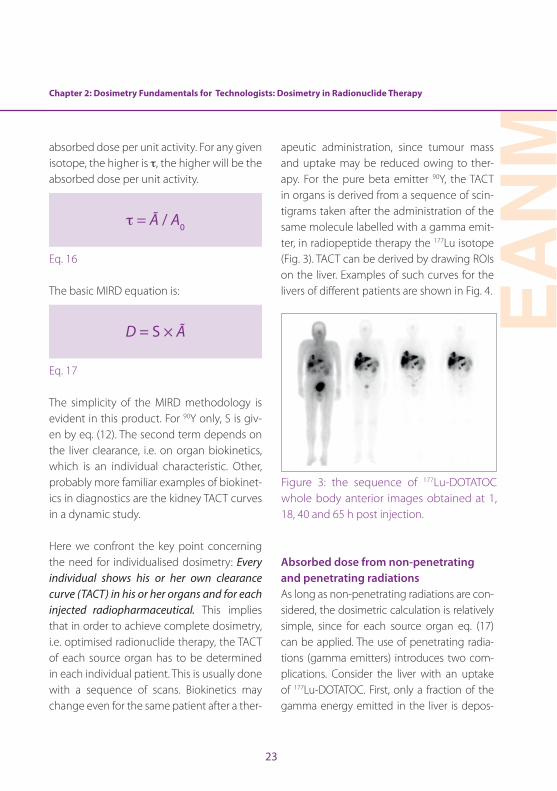
apeutic administration, since tumour mass and uptake may be reduced owing to ther-apy . For the pure beta emitter 90Y, the TACT in organs is derived from a sequence of scin-tigrams taken after the administration of the same molecule labelled with a gamma emit-ter, in radiopeptide therapy the 177Lu isotope (Fig . 3) . TACT can be derived by drawing ROIs on the liver . Examples of such curves for the livers of different patients are shown in Fig . 4 .
Figure 3: the sequence of 177Lu-DOTATOC whole body anterior images obtained at 1, 18, 40 and 65 h post injection .
Absorbed dose from non-penetrating and penetrating radiations As long as non-penetrating radiations are con-sidered, the dosimetric calculation is relatively simple, since for each source organ eq . (17) can be applied . The use of penetrating radia-tions (gamma emitters) introduces two com-plications . Consider the liver with an uptake of 177Lu-DOTATOC . First, only a fraction of the gamma energy emitted in the liver is depos-
24
ited in the liver itself . The S value computation becomes non-trivial . Second, another fraction of gamma energy is deposited out of the liv-er, irradiating all the other target organs . The notation Ss←s (S “from source to source”) is in-troduced for the self-irradiation, and we have a large set of St←s values (S “from source s to target t”) for cross-irradiation . An additional op-erational complexity arises from the fact that after a 177Lu-DOTATOC administration, there are several source organs, primarily liver, spleen, kidney and circulating activity . We need the set of St←s for any possible cross-irradiation .
The often mentioned simplicity of the MIRD schema is apparently lost . This is false, since
all these S values (Snyder’s factors) were cal-culated by the MIRD committee using Mon-te Carlo simulations . These values are now available in tables for many isotopes . They are also available online [12] . Therefore, con-sidering again eq . (17), the main advantage of the MIRD method is that S values are avail-able . Clinical dosimetrists have to measure the biokinetics only, and to determine à for all source organs, i .e . only the second term in eq . (17) . The basic data required for calcu-lation of the S value, used to determine the absorbed fraction for self- and cross-irradia-tion, are the total energy emission for each isotope (physical isotope properties) and the organ geometry .
0.00
0.05
0.10
0.15
0.20
0.25
0.30
0.35
0.40
0 24 48 72
Fractio
nofinjected
activ
ity
t(h)
minimumresidencetime=0.55h
maximumresidencetime=68h
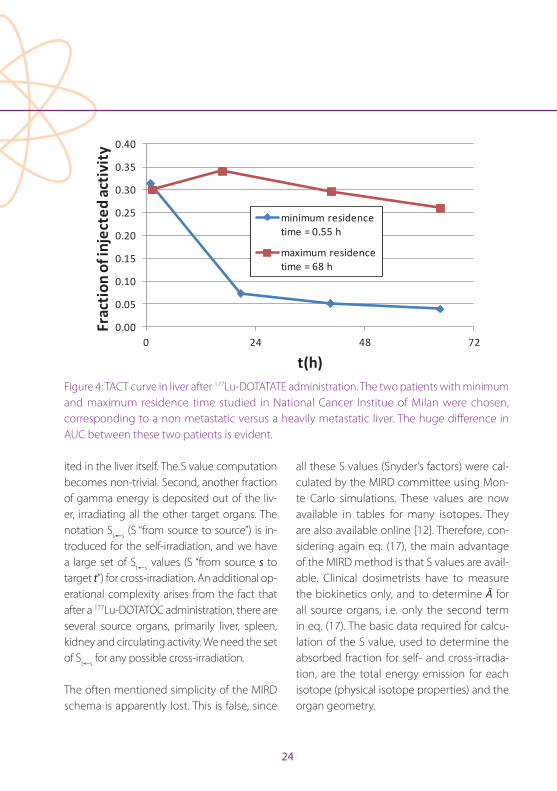
Figure 4: TACT curve in liver after 177Lu-DOTATATE administration . The two patients with minimum and maximum residence time studied in National Cancer Institue of Milan were chosen, corresponding to a non metastatic versus a heavily metastatic liver . The huge difference in AUC between these two patients is evident .
Chapter 2: Dosimetry Fundamentals for Technologists: Dosimetry in Radionuclide Therapy
EAN
M
25
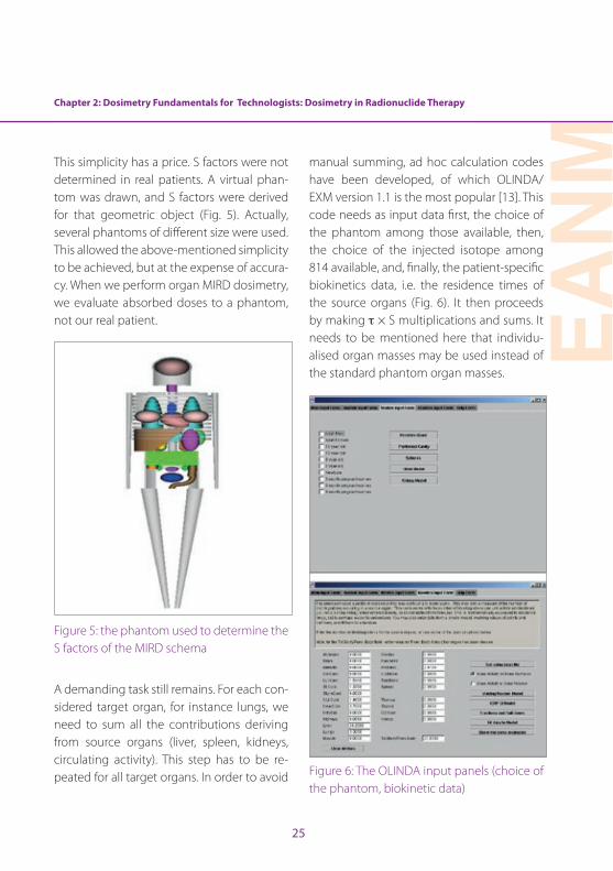
This simplicity has a price . S factors were not determined in real patients . A virtual phan-tom was drawn, and S factors were derived for that geometric object (Fig . 5) . Actually, several phantoms of different size were used . This allowed the above-mentioned simplicity to be achieved, but at the expense of accura-cy . When we perform organ MIRD dosimetry, we evaluate absorbed doses to a phantom, not our real patient .
Figure 5: the phantom used to determine the S factors of the MIRD schema
A demanding task still remains . For each con-sidered target organ, for instance lungs, we need to sum all the contributions deriving from source organs (liver, spleen, kidneys, circulating activity) . This step has to be re-peated for all target organs . In order to avoid
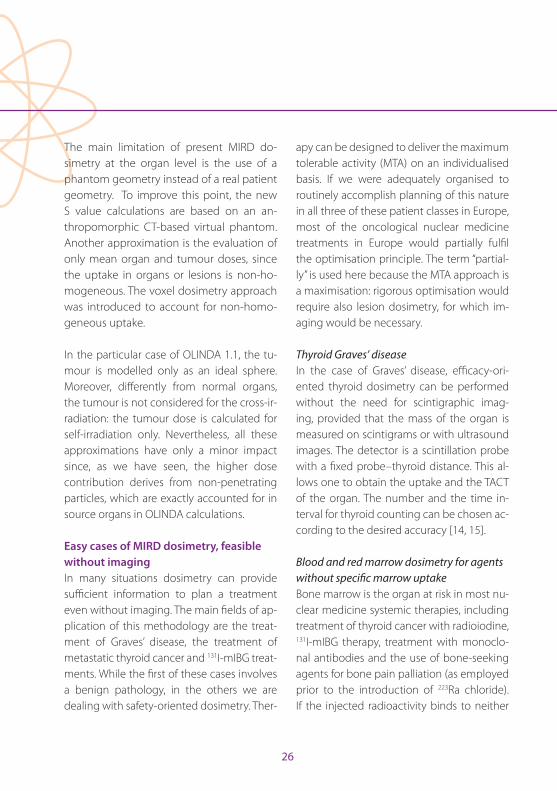
manual summing, ad hoc calculation codes have been developed, of which OLINDA/EXM version 1 .1 is the most popular [13] . This code needs as input data first, the choice of the phantom among those available, then, the choice of the injected isotope among 814 available, and, finally, the patient-specific biokinetics data, i .e . the residence times of the source organs (Fig . 6) . It then proceeds by making τ × S multiplications and sums . It needs to be mentioned here that individu-alised organ masses may be used instead of the standard phantom organ masses .
Figure 6: The OLINDA input panels (choice of the phantom, biokinetic data)
26
The main limitation of present MIRD do-simetry at the organ level is the use of a phantom geometry instead of a real patient geometry . To improve this point, the new S value calculations are based on an an-thropomorphic CT-based virtual phantom . Another approximation is the evaluation of only mean organ and tumour doses, since the uptake in organs or lesions is non-ho-mogeneous . The voxel dosimetry approach was introduced to account for non-homo-geneous uptake .
In the particular case of OLINDA 1 .1, the tu-mour is modelled only as an ideal sphere . Moreover, differently from normal organs, the tumour is not considered for the cross-ir-radiation: the tumour dose is calculated for self-irradiation only . Nevertheless, all these approximations have only a minor impact since, as we have seen, the higher dose contribution derives from non-penetrating particles, which are exactly accounted for in source organs in OLINDA calculations .
Easy cases of MIRD dosimetry, feasible without imaging In many situations dosimetry can provide sufficient information to plan a treatment even without imaging . The main fields of ap-plication of this methodology are the treat-ment of Graves’ disease, the treatment of metastatic thyroid cancer and 131I-mIBG treat-ments . While the first of these cases involves a benign pathology, in the others we are dealing with safety-oriented dosimetry . Ther-
apy can be designed to deliver the maximum tolerable activity (MTA) on an individualised basis . If we were adequately organised to routinely accomplish planning of this nature in all three of these patient classes in Europe, most of the oncological nuclear medicine treatments in Europe would partially fulfil the optimisation principle . The term “partial-ly” is used here because the MTA approach is a maximisation: rigorous optimisation would require also lesion dosimetry, for which im-aging would be necessary .
Thyroid Graves’ diseaseIn the case of Graves’ disease, efficacy-ori-ented thyroid dosimetry can be performed without the need for scintigraphic imag-ing, provided that the mass of the organ is measured on scintigrams or with ultrasound images . The detector is a scintillation probe with a fixed probe–thyroid distance . This al-lows one to obtain the uptake and the TACT of the organ . The number and the time in-terval for thyroid counting can be chosen ac-cording to the desired accuracy [14, 15] .
Blood and red marrow dosimetry for agents without specific marrow uptakeBone marrow is the organ at risk in most nu-clear medicine systemic therapies, including treatment of thyroid cancer with radioiodine, 131I-mIBG therapy, treatment with monoclo-nal antibodies and the use of bone-seeking agents for bone pain palliation (as employed prior to the introduction of 223Ra chloride) . If the injected radioactivity binds to neither
Chapter 2: Dosimetry Fundamentals for Technologists: Dosimetry in Radionuclide Therapy
EAN
M
27
bone nor red marrow nor blood particles, an easy method of dosimetry for blood or red marrow is possible provided that the TACT of the activity concentration in blood sam-ples and the whole-body activity burden are measured [16, 17] . The necessary instrumen-tation is a gamma counter to count blood samples and a spectroscopic probe or Gei-ger counter to count the patient body, with a reproducible patient–detector distance . Data collection should last several days, and ide-ally up to the 6th day for blood sampling in radioiodine therapy .
131I-mIBG whole-body dosimetryThis method was developed as a simpli-fication of red marrow dosimetry to treat neuroblastoma in children, in whom repeat-ed blood withdrawal is inappropriate . In 131I-mIBG therapy of paediatric patients, the whole-body dose has been demonstrated to correlate with haematological toxicity [18] . A limit of 2 Gy whole-body absorbed dose is generally accepted . Since this kind of therapy is based on repeated administra-tions, peri-therapeutic dosimetry after the first administration can be used to plan the subsequent administrations . The dosimetric method is based on a sequence of whole-body counts (minimum two per day) taken during the hospitalisation for therapy using a Geiger counter fixed on the ceiling above the patient’s bed or a portable counter at a fixed distance from the patient . Usually the geometric mean G = √A P of anterior A and posterior P counts is considered . The TACT
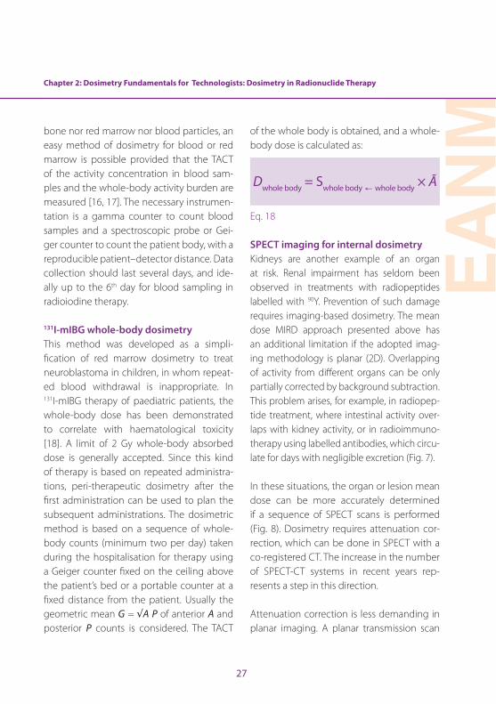
of the whole body is obtained, and a whole-body dose is calculated as:
Dwhole body = Swhole body ← whole body × Ã
Eq . 18
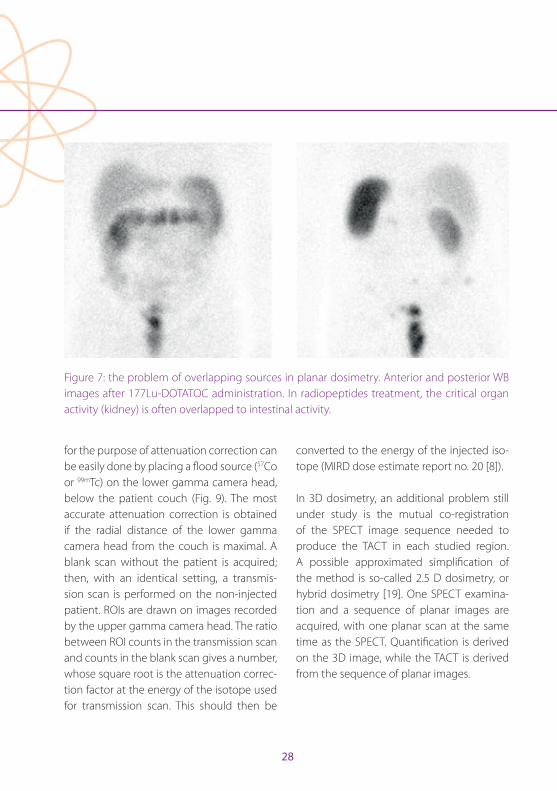
SPECT imaging for internal dosimetryKidneys are another example of an organ at risk . Renal impairment has seldom been observed in treatments with radiopeptides labelled with 90Y . Prevention of such damage requires imaging-based dosimetry . The mean dose MIRD approach presented above has an additional limitation if the adopted imag-ing methodology is planar (2D) . Overlapping of activity from different organs can be only partially corrected by background subtraction . This problem arises, for example, in radiopep-tide treatment, where intestinal activity over-laps with kidney activity, or in radioimmuno-therapy using labelled antibodies, which circu-late for days with negligible excretion (Fig . 7) .
In these situations, the organ or lesion mean dose can be more accurately determined if a sequence of SPECT scans is performed (Fig . 8) . Dosimetry requires attenuation cor-rection, which can be done in SPECT with a co-registered CT . The increase in the number of SPECT-CT systems in recent years rep-resents a step in this direction .
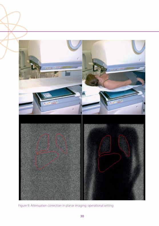
Attenuation correction is less demanding in planar imaging . A planar transmission scan
28
for the purpose of attenuation correction can be easily done by placing a flood source (57Co or 99mTc) on the lower gamma camera head, below the patient couch (Fig . 9) . The most accurate attenuation correction is obtained if the radial distance of the lower gamma camera head from the couch is maximal . A blank scan without the patient is acquired; then, with an identical setting, a transmis-sion scan is performed on the non-injected patient . ROIs are drawn on images recorded by the upper gamma camera head . The ratio between ROI counts in the transmission scan and counts in the blank scan gives a number, whose square root is the attenuation correc-tion factor at the energy of the isotope used for transmission scan . This should then be
converted to the energy of the injected iso-tope (MIRD dose estimate report no . 20 [8]) .
In 3D dosimetry, an additional problem still under study is the mutual co-registration of the SPECT image sequence needed to produce the TACT in each studied region . A possible approximated simplification of the method is so-called 2 .5 D dosimetry, or hybrid dosimetry [19] . One SPECT examina-tion and a sequence of planar images are acquired, with one planar scan at the same time as the SPECT . Quantification is derived on the 3D image, while the TACT is derived from the sequence of planar images .
Figure 7: the problem of overlapping sources in planar dosimetry . Anterior and posterior WB images after 177Lu-DOTATOC administration . In radiopeptides treatment, the critical organ activity (kidney) is often overlapped to intestinal activity .

Chapter 2: Dosimetry Fundamentals for Technologists: Dosimetry in Radionuclide Therapy
EAN
M
29
Figure 8: SPECT-CT dosimetry after 177Lu-DOTATOC administration .critical organ activity (kidney) is often overlapped to intestinal activity .
PET imaging for internal dosimetryPET imaging is now a routine in dosimetry [20], especially after 90Y radioembolisation (Fig . 1, lower right) . Here the problem is the infinitesimal positron emission from 90Y (32 per million decays), which requires acquisi-tion times of 15 min per bed position with two bed positions to cover the liver and results in unavoidably noisy images despite the long acquisition time . The huge advan-tage in radioembolization dosimetry derives from the permanent trapping of micro-spheres: just one scan is sufficient since TACT is given by the physical decay of 90Y .
The enhanced image quality in comparison with SPECT is outstanding in iodine imaging . Iodine-124 PET should be used for accurate staging after thyroidectomy, given the low diagnostic sensitivity of 131I whole-body scan,
and not only for dosimetric purposes [21] .
Convolution and direct Monte Carlo methodsConvolution methods go beyond the evalu-ation of organ mean dose . They aim to com-pute the absorbed dose point by point, at any location in the studied object . Voxel do-simetry and dose point kernel dosimetry are similar in that the dose from a point or voxel source to the surroundings is calculated . This calculation is repeated for all source voxels, adding the contribution of each source vox-el to all target voxels . This process is termed convolution . It overcomes the phantom ge-ometry limits of the MIRD approach . Snyder (S) factors from voxel to voxel are also avail-able . Commercial software can be employed for dosimetry using convolution methods .
Convolution methods can be successfully applied to homogeneous tissues, while in inhomogeneous tissues or at organ–organ interfaces (e .g . bone–tissue or liver–lung), direct Monte Carlo simulation is the most reliable, though also the most demanding calculation . It is based on the simulation of each single radionuclide decay, following the history of the emitted beta and gamma rays, with their probabilistic interactions . The deposited energy from each interaction is recorded . The process is repeated with a dif-ferent random fate for some ten millions of decays, obtaining a 3D inhomogeneous ab-sorbed dose distribution .
30
Figure 9: Attenuation correction in planar imaging: operational setting
Chapter 2: Dosimetry Fundamentals for Technologists: Dosimetry in Radionuclide Therapy
EAN
M
31
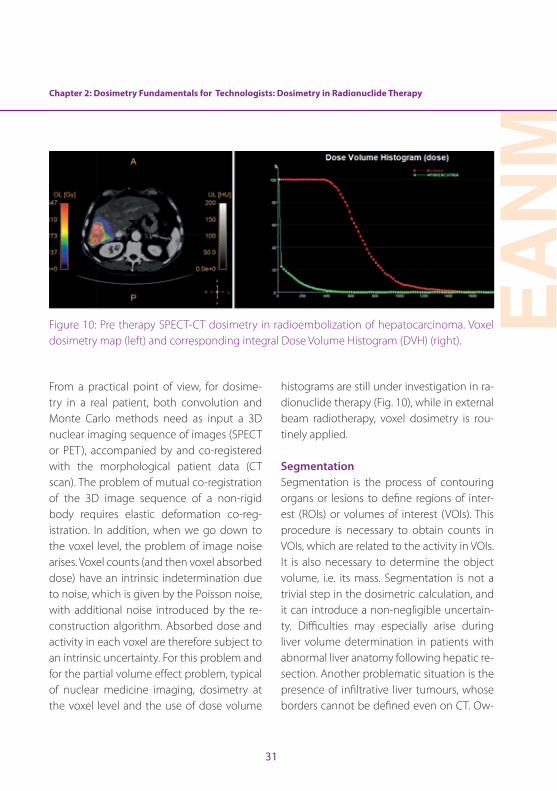
Figure 10: Pre therapy SPECT-CT dosimetry in radioembolization of hepatocarcinoma . Voxel dosimetry map (left) and corresponding integral Dose Volume Histogram (DVH) (right) .
From a practical point of view, for dosime-try in a real patient, both convolution and Monte Carlo methods need as input a 3D nuclear imaging sequence of images (SPECT or PET), accompanied by and co-registered with the morphological patient data (CT scan) . The problem of mutual co-registration of the 3D image sequence of a non-rigid body requires elastic deformation co-reg-istration . In addition, when we go down to the voxel level, the problem of image noise arises . Voxel counts (and then voxel absorbed dose) have an intrinsic indetermination due to noise, which is given by the Poisson noise, with additional noise introduced by the re-construction algorithm . Absorbed dose and activity in each voxel are therefore subject to an intrinsic uncertainty . For this problem and for the partial volume effect problem, typical of nuclear medicine imaging, dosimetry at the voxel level and the use of dose volume
histograms are still under investigation in ra-dionuclide therapy (Fig . 10), while in external beam radiotherapy, voxel dosimetry is rou-tinely applied .
SegmentationSegmentation is the process of contouring organs or lesions to define regions of inter-est (ROIs) or volumes of interest (VOIs) . This procedure is necessary to obtain counts in VOIs, which are related to the activity in VOIs . It is also necessary to determine the object volume, i .e . its mass . Segmentation is not a trivial step in the dosimetric calculation, and it can introduce a non-negligible uncertain-ty . Difficulties may especially arise during liver volume determination in patients with abnormal liver anatomy following hepatic re-section . Another problematic situation is the presence of infiltrative liver tumours, whose borders cannot be defined even on CT . Ow-
32
ing to the need for segmentation, dosimetry is dependent on the skills of the operator . The optimal threshold for segmenting an ob-ject in order to obtain quantitatively accurate information is a general problem in nuclear medicine, an example being segmentation for FDG PET target volume delineation for ra-diotherapy treatment planning [22] .
Segmentation requires knowledge of basic anatomy . For this reason, technologists can be usefully employed in this activity . During this work they are usually supervised by an experienced radiologist .
QuantificationRegardless of the kind of dosimetry, the amount of activity in source regions (organs or voxels) needs to be determined . The first requirement is an accurate dose calibrator to measure the administered activity and its residue . In whole-body dosimetry, quan-tification is immediate since the first body count is taken immediately after the admin-istration, before urinary bladder voiding . Set-ting the correspondence between obtained initial whole body counts and the known injected activity allows one to proportionally calculate the activity burden in subsequent counts . This is called “patient relative calibra-tion” . Calibration of the gamma counter is required to convert the blood sample count rate in a tube into activity, with a correction for non-linearity effects .
The quantification on images is more com-plex . In contrast to PET scanners, gamma cameras were not conceived to be quantita-tive . Only the last model of a producer was developed ad hoc, with new hardware and software, in order to provide quantitative SPECT, and then only for 99mTc . PET scanners are usually considered quantitative, but is-sues arise when non-conventional isotopes are employed, such as 90Y [23] or 124I .
Quantitative imaging requires the imple-mentation of all the possible corrections for physical effects (attenuation, scatter, dead time, partial volume effect, resolution recov-ery and, for PET, random correction and time of flight) . A system calibration is then nec-essary, to convert the count rate in a VOI to activity . This requires a phantom containing a known activity: such a phantom can be a point source or an extended phantom, or a hot insert in a water phantom . If a phan-tom is used, an absolute system calibration is performed . In some particular situations, each patient can be the “calibration phan-tom” for him- or herself . In the case of liver radioembolisation, the known activity can be imaged on one SPECT or PET scan and can be set in correspondence with the obtained counts (patient relative calibration method, cf . above) . Technologists can play a useful role in the calibration process owing to their technical competence on scanners and their authorisation to handle radioactivity .
Chapter 2: Dosimetry Fundamentals for Technologists: Dosimetry in Radionuclide Therapy
EAN
M
33
The necessity of the technologist in clinical dosimetry The Dosimetry Committee of the EANM has been actively promoting the implementa-tion of dosimetric optimisation of radionu-clide therapy for more than a decade . It is not predictable when and to what extent such optimisation will be accomplished . What is beyond doubt is that such an advance on a large scale cannot happen without the em-ployment of technologists . By law, physicists have the responsibility for dose calculations, but several preliminary operations can and should be done by technologists .
In the Nuclear Medicine Division of the National Cancer Institute of Milan, several theses on dosimetry have been written by technologists, including two that addressed in particular the role of the technologist in clinical dosimetry . In such institutions, not only data acquisition (patient handling and scanning, whole body counting, blood sample counting) but also segmentation is ordinarily performed by technologists . Tech-nologists therefore have an essential role in the implementation of clinical dosimetry in radionuclide treatments .
Guidelines of the EANM Dosimetry CommitteeThe EANM website, under the section “publi-cation” [24], offers a list of published dosime-try guidelines that are freely downloadable .
DisclosureCarlo Chiesa received honoraria during the past two years from BTG Biocompatibles for lectures, consultancy and one symposium during the 2015 EANM Congress . He was supported by BTG Biocompatibles at the last two EANM Congresses . In 2015 he was also a consultant for MedPace core lab .
The other authors have nothing to disclose .
Ethical policyThis work has an educational goal . All clini-cal images contained herein were acquired for diagnostic or therapeutic purposes for patient care, after procurement of signed informed consent, before this chapter was compiled . Images were copied here for edu-cational purposes .
34
References
1 . ICRU Report 67: Absorbed-dose specification in nu-clear medicine . International Commission on Radiation Units and Measurements, July 2002 . Ashford, Kent, UK: Nuclear Technology Publishing . http://www .ntp .org .uk . ISSN 1473-6691 .
2 . http://www .icrp .org/publications .asp
3 . Sgouros G, Roeske JC, McDevitt MR, Palm S, Allen BJ, Fisher DR, et al . MIRD Pamphlet No . 22 (abridged): ra-diobiology and dosimetry of alpha-particle emitters for targeted radionuclide therapy . J Nucl Med 2010;51:311–328 .
4 . Kennedy AS, McNeillie P, Dezarn WA, Nutting C, Sangro B, Wertman D, et al . Treatment parameters and outcome in 680 treatments of internal radiation with resin 90Y-mi-crospheres for unresectable hepatic tumors . Int J Radiat Oncol Biol Phys 2009;74:1494–1500 .
5 . Mazzaferro V, Sposito C, Bhoori S, Romito R, Chiesa C, Morosi C, et al . Yttrium90 radioembolization for inter-mediate-advanced hepatocarcinoma: a phase II study . Hepatology 2013;57:1826–1837 .
6 . http://eur-lex .europa .eu/legal-content/EN/TXT/PD-F/?uri=CELEX:32013L0059&from=EN
7 . Loevinger R, Budinger TF, Watson EE . MIRD primer for absorbed dose calculations . Society of Nuclear Med-icine, 1991 .
8 . http://www .snmmi .org/ClinicalPractice/content .aspx-?ItemNumber=4363
9 . Sgouros G . Dosimetry of internal emitters J Nucl Med 2005;46:18s–27s .
10 . Zanzonico PB . Internal radionuclide radiation dosimetry: a review of basic concepts and recent developments . J Nucl Med 2000;41:297–308 .
11 . Stabin M . Demystifying internal dose calculations . www .doseinfo-radar .com/demystify .doc
12 . http://www .doseinfo-radar .com; also Health Physics 2003;85:294–310 .
13 . Stabin MG, Sparks RB, Crowe E . OLINDA/EXM: the sec-ond-generation personal computer software for inter-nal dose assessment in nuclear medicine . J Nucl Med 2005;46:1023–1027 .
14 . Hänscheid H, Canzi C, Eschner W, Flux G, Luster M, Stri-gari L, Lassmann M . EANM Dosimetry Committee Series on Standard Operational Procedures for Pre-Therapeutic Dosimetry II . Dosimetry prior to radioiodine therapy of benign thyroid diseases . 2013 . http://www .eanm .org/publications/guidelines/index .php?navId=37
15 . Hänscheid H, Canzi C, Eschner W, Flux G, Luster M, Strigari L, Lassmann M . EANM Dosimetry Committee Series on Standard Operational Procedures for Pre-Ther-apeutic Dosimetry II . Dosimetry prior to radioiodine therapy of benign thyroid diseases (Supplement) . 2013 . http://www .eanm .org/publications/guidelines/index .php?navId=37
16 . Lassmann M, Hänscheid H, Chiesa C, Hindorf C, Flux G, Luster M . EANM Dosimetry Committee Series on Standard Operational Procedures for Pre-Therapeutic Dosimetry I . Blood and bone marrow dosimetry in dif-ferentiated thyroid cancer therapy . 2008 . http://www .eanm .org/publications/guidelines/index .php?navId=37
17 . Hindorf C, Glatting G, Chiesa C, Lindén O, Flux G . EANM Dosimetry Committee guidelines for bone marrow and whole-body dosimetry . http://www .eanm .org/publica-tions/guidelines/index .php?navId=37
18 . Fielding SL, Flower MA, Ackery D, Kemshead JT, Lashford LS, Lewis I . Dosimetry of iodine 131 metaiodobenzil-guanidine for treatment of resistant neuroblastoma: results of a UK study . Eur J Nucl Med 1991;18:308–316 .
19 . Ferrer L, Kraeber-Bodéré F, Bodet-Milin C, Rousseau C, Le Gouill S, Wegener WA, et al . Three methods assessing red marrow dosimetry in lymphoma patients treated with radioimmunotherapy . Cancer 2010;116 (4 Sup-pl):1093–1100 .
20 . Lhommel R, van Elmbt L, Goffette P, Van den Eynde M, Jamar F, Pauwels S, Walrand S . Feasibility of 90Y TOF PET-based dosimetry in liver metastasis therapy using SIR-Spheres . Eur J Nucl Med Mol Imaging 2010;37:1654–1662 .
Chapter 2: Dosimetry Fundamentals for Technologists: Dosimetry in Radionuclide Therapy
EAN
M
35
21 . Wierts R, Brans B, Havekes B, Kemerink G, Halders S, Schaper N, et al . Dose-response relationship in differen-tiated thyroid cancer patients undergoing radioiodine treatment assessed by means of 124I PET/CT . J Nucl Med 2016;57:1027–1032 . Feb 25 .
22 . Brambilla M,_ Matheoud R, Secco C, Loi G, Krengli M, Inglese E . Threshold segmentation for PET target vol-ume delineation in radiation treatment planning: the role of target-to-background ratio and target size . Med Phys 2008;35:1207–1213 .
23 . Willowson KP, Tapner M, The QUEST Investigator Team, Bailey DL . A multicentre comparison of quantitative 90Y PET/CT for dosimetric purposes after radioembolization with resin microspheres – The QUEST Phantom Study . Eur J Nucl Med Mol Imaging 2015;42:1202–1222 .
24 . http://www .eanm .org/publications/guidelines/index .php?navId=37
36
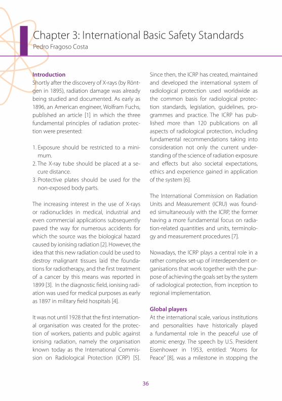
Chapter 3: International Basic Safety StandardsPedro Fragoso Costa
IntroductionShortly after the discovery of X-rays (by Rönt-gen in 1895), radiation damage was already being studied and documented . As early as 1896, an American engineer, Wolfram Fuchs, published an article [1] in which the three fundamental principles of radiation protec-tion were presented:
1 . Exposure should be restricted to a mini-mum .
2 . The X-ray tube should be placed at a se-cure distance .
3 . Protective plates should be used for the non-exposed body parts .
The increasing interest in the use of X-rays or radionuclides in medical, industrial and even commercial applications subsequently paved the way for numerous accidents for which the source was the biological hazard caused by ionising radiation [2] . However, the idea that this new radiation could be used to destroy malignant tissues laid the founda-tions for radiotherapy, and the first treatment of a cancer by this means was reported in 1899 [3] . In the diagnostic field, ionising radi-ation was used for medical purposes as early as 1897 in military field hospitals [4] .
It was not until 1928 that the first internation-al organisation was created for the protec-tion of workers, patients and public against ionising radiation, namely the organisation known today as the International Commis-sion on Radiological Protection (ICRP) [5] .
Since then, the ICRP has created, maintained and developed the international system of radiological protection used worldwide as the common basis for radiological protec-tion standards, legislation, guidelines, pro-grammes and practice . The ICRP has pub-lished more than 120 publications on all aspects of radiological protection, including fundamental recommendations taking into consideration not only the current under-standing of the science of radiation exposure and effects but also societal expectations, ethics and experience gained in application of the system [6] .
The International Commission on Radiation Units and Measurement (ICRU) was found-ed simultaneously with the ICRP, the former having a more fundamental focus on radia-tion-related quantities and units, terminolo-gy and measurement procedures [7] .
Nowadays, the ICRP plays a central role in a rather complex set-up of interdependent or-ganisations that work together with the pur-pose of achieving the goals set by the system of radiological protection, from inception to regional implementation .
Global playersAt the international scale, various institutions and personalities have historically played a fundamental role in the peaceful use of atomic energy . The speech by U .S . President Eisenhower in 1953, entitled: “Atoms for Peace” [8], was a milestone in stopping the
EAN
M
37
Chapter 3: International Basic Safety Standards
“nuclear race” with the former Soviet Union and in delivering a sense of security that the nuclear disasters from Hiroshima and Naga-saki would not be repeated . This speech also laid down the ideological background for the creation of the International Atomic Energy Agency (IAEA) and the United Nations Scien-tifi c Committee on the Eff ects of Atomic Ra-diation (UNSCEAR) . The latter, created in 1955, became the offi cial international authority responsible for controlling the levels and ef-fects of ionising radiation from all possible sources, whether peaceful, military, man-made or natural [9] . In 1957 the IAEA was cre-ated and empowered to take actions on the development of nuclear energy for peaceful purposes, to provide materials and assistance
for practical applications of atomic energy (e .g . energy, industry and health) relevant to the needs of underdeveloped areas of the world, to foster the exchange of scientifi c and technical knowledge and, fi nally, to establish or adopt nuclear safety standards [10] .
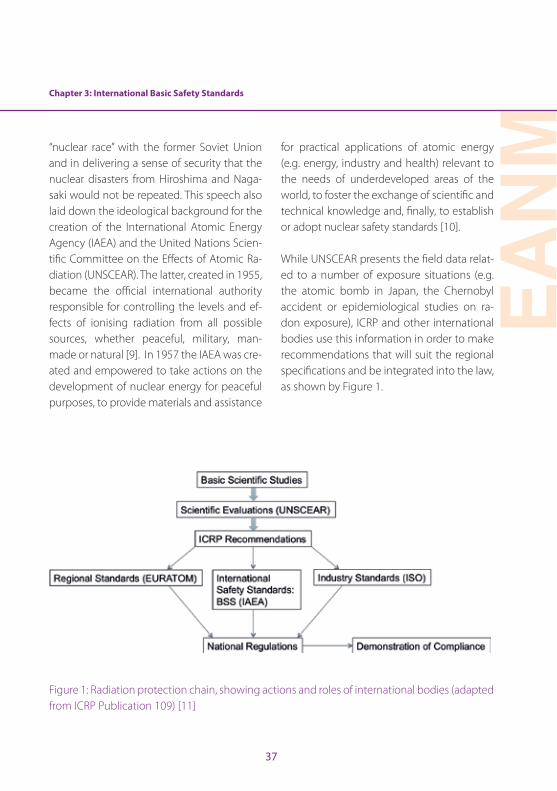
While UNSCEAR presents the fi eld data relat-ed to a number of exposure situations (e .g . the atomic bomb in Japan, the Chernobyl accident or epidemiological studies on ra-don exposure), ICRP and other international bodies use this information in order to make recommendations that will suit the regional specifi cations and be integrated into the law, as shown by Figure 1 .
Figure 1: Radiation protection chain, showing actions and roles of international bodies (adapted from ICRP Publication 109) [11]
38
International System of Radiological ProtectionSince its foundation, the International Sys-tem of Radiological Protection has been subject to many updates and fundamental changes . Over the years, not only have dose quantities and their units been redefined, but weighting factors and body-related dose quantities have been revised and dose limita-tions for occupational and public exposures, redefined . Despite the continual implemen-tation of this self-optimisation process, the fundamental principles of radiation protec-tion were in fact defined in the first ICRP rec-ommendations in 1958 [12]: “The objectives of radiation protection are to prevent or minimise somatic injuries and to minimise the deterioration of the genetic constitution of the population” . Nowadays, this principle has been reformulated as the prevention of deterministic effects caused by high doses (mainly of an acute nature and appearing after a known dose threshold) and the re-duction of stochastic effects caused by both high and low doses and that can be detected a long time after exposure [13] .
The concept of dose has been introduced as the quantity of interest relating physical measurements with biological effects of ra-diation . The term “dose” has been medically appropriated in analogy to the pharmaco-logical dose, as used in the prescription of a medicine [14] . However, there are situations in which exposure to radiation is not related to a medical act . Differentiation of exposure situations is, therefore, a fundamental topic
in radiation protection . There are three cate-gories of exposure:
• Occupational exposures: those exposures that occur in a range of industries, medical institutions, educational and research establishments and nuclear fuel cycle facilities [15]
• Public exposures: exposures to natural radiation sources and man-made sources [16]
• Medical exposures: exposures of patients and comforters, carers or volunteers in research and in diagnostic, interventional and therapeutic procedures [17]
Three exposure situations have been de-fined, which are considered to encompass the entire range of possible situations involv-ing exposure [18]:
• Planned exposure situations: those situations in which a radioactive source is introduced or operated in a set-up designed for that purpose
• Emergency exposure situations: unexpected situations that arise from planned exposures and require urgent attention
• Existing exposure situations: situations that exist regardless of any protective act or decision, mainly regarded as natural background radiation
The use of radiation in Nuclear Medicine is a planned exposure situation . All workers and facilities need to be under regulatory
Chapter 3: International Basic Safety Standards
EAN
M
39
control, with appropriate authorisation from the competent authority in order to operate . There are situations in which incidents, acci-dents or errors (e .g . radiopharmaceutical mis-administration, spills or contamination) result in a potential exposure [19] . A potential ex-posure may result from an accident involving a source or an event or sequence of events of a probabilistic nature, including equipment failures and operating errors .
The most important part in a system of radio-logical protection is the ruling principles that apply to all situations and persons involved . Again, there are three fundamental princi-ples of radiation protection [13]:
1 . The principle of justification: Any change to an exposure situation (e .g . a decision to perform a PET/CT scan, changing from an existing exposure to a planned exposure situation) should result in a net benefit to the individual .
2 . The principle of optimisation of protection: The likelihood of incurring exposures, the number of people exposed and the mag-nitude of their individual doses should all be kept as low as reasonably achievable (this is commonly known as the ALARA principle), taking into account economic and societal factors .
3 . The principle of limitation of doses: The total dose to any individual from planned expo-sures, with the exception of medical expo-sures of patients, should not exceed the
established limits (only applies to the occu-pational and public exposure categories) .
IAEA International Basic Safety Standards (IBSS)As mentioned previously, the development and application support of safety standards is a statutory function of the IAEA . To achieve this mission, IAEA periodically publishes Safety Standard Series, which cover nuclear safety, radiation safety, transport safety and waste safety . The IBSS are a part of the safe-ty requirements category within the IAEA scheme . The latest IBSS [20] is a joint effort of the European Commission (EC), the Food and Agriculture Organization of the United Nations (FAO), the IAEA, the International Labour Organization (ILO), the OECD Nuclear Energy Agency (OECD/NEA), the Pan Ameri-can Health Organization (PAHO), the United Nations Environment Programme (UNEP) and the World Health Organization (WHO) and uses the latest recommendations pro-vided by ICRP [13], in particular with atten-tion to the possible exposure situations .
In general all safety standards follow the fundamental principle of protecting people from the hazardous effects of ionising radi-ation . In all possible interactions in which a radioactive source could produce damage to an individual, there is a role for protec-tion . There is, however, a difference between these two concepts: while radiation protec-tion is mainly focussed in controlling expo-sure to a source, to attenuate its effects, ra-diation safety is about maintaining control
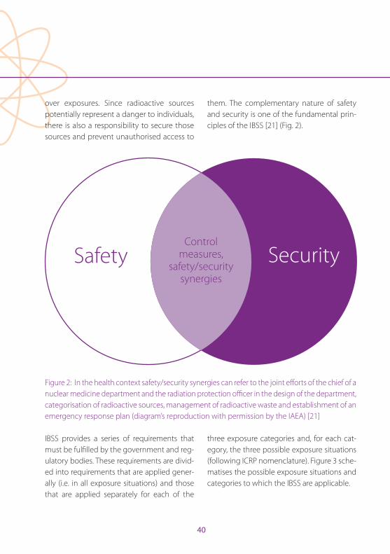
40
over exposures . Since radioactive sources potentially represent a danger to individuals, there is also a responsibility to secure those sources and prevent unauthorised access to
them . The complementary nature of safety and security is one of the fundamental prin-ciples of the IBSS [21] (Fig . 2) .
Safety Security
Control measures,
safety/security synergies
Figure 2: In the health context safety/security synergies can refer to the joint efforts of the chief of a nuclear medicine department and the radiation protection officer in the design of the department, categorisation of radioactive sources, management of radioactive waste and establishment of an emergency response plan (diagram’s reproduction with permission by the IAEA) [21]
IBSS provides a series of requirements that must be fulfilled by the government and reg-ulatory bodies . These requirements are divid-ed into requirements that are applied gener-ally (i .e . in all exposure situations) and those that are applied separately for each of the
three exposure categories and, for each cat-egory, the three possible exposure situations (following ICRP nomenclature) . Figure 3 sche-matises the possible exposure situations and categories to which the IBSS are applicable .
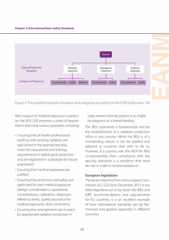
Chapter 3: International Basic Safety Standards
EAN
M
41
Type of exposure Situation
Category of Exposure Occupational Occupational OccupationalPublic Public PublicMedical
Planned Exposure
Emergency Exposure
Existing Exposure
Source
Figure 3: The possible exposure situations and categories according to the ICRP publication 103
With respect to medical exposure in particu-lar, the IBSS [20] presents a series of require-ments that have various purposes, including:
• Ensuring that all health professionals working with ionising radiation are specialised in the appropriate area, meet the educational and training requirements in radiological protection and are registered in a database for future assessment
• Ensuring that medical exposures are justified
• Ensuring that protection and safety are optimised for each medical exposure (design considerations, operational considerations, calibration, diagnostic reference levels, quality assurance for medical exposures, dose constraints)
• Ensuring that arrangements are in place for appropriate radiation protection in
cases where a female patient is or might be pregnant or is breast-feeding
The IBSS represents a fundamental tool for the establishment of a radiation protection office in any country . While the IBSS is of a non-binding nature, it can be applied and adapted in countries that wish to do so . However, if a country asks the IAEA for IBSS co-sponsorship, then compliance with the security standards is a condition that must be met in order to receive assistance .
European legislationThe recent directive from the European Com-mission (EC) [22] from December 2013 is the latest legislative act to lay down the IBSS and ICRP recommendations and requirements for EU countries . It is an excellent example of how international standards can be har-monised and applied regionally in different countries .
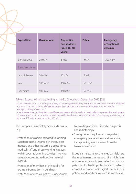
42
Type of limit Occupational Apprentices and students (aged 16–18 years)
Public Emergency occupational exposure
Effective dose 20 mSva 6 mSv 1 mSv <100 mSvd
Equivalent doses:
Lens of the eye 20 mSvb 15 mSv 15 mSv
Skin 500 mSvc 150 mSvc 150 mSvc
Extremities 500 mSv 150 mSv 150 mSv
Table 1: Exposure limits according to the EU Directive of December 2013 [22]a In special situations up to 50 mSv/year, as long as the averaged dose in any 5 consecutive years is not above 20 mSv/yearb In special situations up to 50 mSv/year, as long as the total dose in any 5 consecutive years is under 100 mSvc Averaged over any area of 1 cm2
d In exceptional situations, in order to save life, prevent severe radiation-induced health effects or prevent the development of catastrophic conditions, a reference level for an effective dose from external radiation of emergency workers may be set above 100 mSv, but not exceeding 500 mSv
The European Basic Safety Standards ensure [23]:
• Protection of workers exposed to ionising radiation, such as workers in the nuclear industry and other industrial applications, medical staff and those working in places with indoor radon or in activities involving naturally occurring radioactive material (NORM)
• Protection of members of the public, for example from radon in buildings
• Protection of medical patients, for example
by avoiding accidents in radio-diagnosis and radiotherapy
• Strengthened requirements regarding emergency preparedness and response, incorporating lessons learnt from the Fukushima accident
Especially relevant to the medical field are the requirements in respect of a high level of competence and clear definition of com-petencies for health professionals in order to ensure the proper radiological protection of patients and workers involved in medical ra-
Chapter 3: International Basic Safety Standards
EAN
M
43
diation (as set out in the European Directive 2013/59/Euratom [24]) . The directive is also an excellent reference document, since it includes modern technical data (e .g . activity concentration values for exemption or clear-ance of materials that can be applied, radia-tion weighing factors, tissue weighing factors and effective dose calculation formulas) re-lated mainly to the latest ICRP publication . At the same time it provides new dose limits, in particular with regard to the eye lens . Table 1 summarises the yearly dose limits for work-ers (covering all authorised practices) and for apprentices and students (aged between 16 and 18 years) who, during the course of their studies, are obliged to work with radioactive sources and the general public . The emergen-cy occupational exposure limit is also shown; it must be ensured that emergency workers liable to incur an effective dose exceeding 100 mSv are informed in advance of the risks and the available protection methods .
All recent publications have placed special emphasis on the use of optimisation tools when managing planned exposures . The annual effective dose limit is a regulatory act that applies to different groups of profession-als (e .g . health professionals, reactor operators and researchers) . Since this is non-specific to the nature of each individual occupation, it is never to be expected that medical technol-ogists will even approach the effective dose limit within any given year . In these cases, a prospective upper bound of individual dos-es, known as dose constraint, can be used to
define the range of options considered in the process of optimisation for a given radiation source in a planned exposure situation .
Nuclear medicineThe practice of nuclear medicine is regulat-ed by the member states’ authorities, whose stance is influenced by the existing recom-mendations (Fig . 1) . The IAEA provides, in addition to the general IBSS, practice-specific regulatory guidance, including with respect to the safe practice of nuclear medicine [25] .
All aspects of nuclear medicine are subject to safety requirements, including certification, application of radiation principles (justification of practices, limitation of doses and optimisa-tion of protection), quality assurance of proce-dures and equipment, facility design and secu-rity of sources . In all these areas, health profes-sionals have the responsibility for protection and safety, and the avoidance of accidental exposures resulting from decisions, operation/handling of sources or equipment . Potential accidental exposures may relate to the patient (e .g . radiopharmaceutical misadministration), the health professional (e .g . loss of radioactive shipment, damage to Tc-generator or radioac-tive spills) or all persons in the department (e .g . fire) . In order to avoid or minimise occurrenc-es of these kinds, it is essential for the health professional both to possess knowledge of the factors that may lead to accidental exposures and to provide written operational protocols and materials (i .e . emergency kit) to be used in the event that such exposures occur .
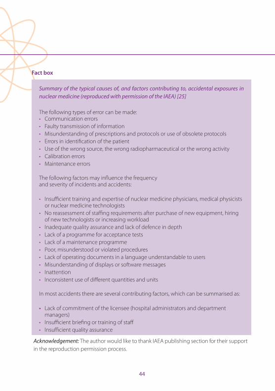
44
Fact box Summary of the typical causes of, and factors contributing to, accidental exposures in nuclear medicine (reproduced with permission of the IAEA) [25]
The following types of error can be made:• Communication errors• Faulty transmission of information• Misunderstanding of prescriptions and protocols or use of obsolete protocols• Errors in identification of the patient• Use of the wrong source, the wrong radiopharmaceutical or the wrong activity• Calibration errors• Maintenance errors The following factors may influence the frequency and severity of incidents and accidents:
• Insufficient training and expertise of nuclear medicine physicians, medical physicists or nuclear medicine technologists
• No reassessment of staffing requirements after purchase of new equipment, hiring of new technologists or increasing workload
• Inadequate quality assurance and lack of defence in depth• Lack of a programme for acceptance tests• Lack of a maintenance programme• Poor, misunderstood or violated procedures• Lack of operating documents in a language understandable to users• Misunderstanding of displays or software messages• Inattention• Inconsistent use of different quantities and units
In most accidents there are several contributing factors, which can be summarised as:
• Lack of commitment of the licensee (hospital administrators and department managers)
• Insufficient briefing or training of staff • Insufficient quality assurance
Acknowledgement: The author would like to thank IAEA publishing section for their support in the reproduction permission process .
Chapter 3: International Basic Safety Standards
EAN
M
45
References
1 . Fuchs WC . Effect of the Röntgen rays on the skin . West-ern Electrician 1896;291 .
2 . Sansare K, Khanna V, Karjodkar F . Early victims of X-rays: a tribute and current perception . Dentomaxillofacial Radiol 2011;40:123–125 . doi:10 .1259/dmfr/73488299 .
3 . Mould RF . A century of X rays and radioactivity in medi-cine . 2nd ed . London: CRC Press/Taylor & Francis Group; 1993 .
4 . Churchill WS . The story of the Malakind field force . Lon-don: Longman’s Green & Co .; 1898 .
5 . Kang KW . History and organizations for radiological protection . J Korean Med Sci 2016;31:S4–S5 .
6 . Clarke RH, Valentin J . The history of ICRP and the evo-lution of its policies: Invited by the Commission in Oc-tober 2008 . Ann ICRP 2009;39:75–110 . doi:10 .1016/j .icrp .2009 .07 .009 .
7 . Tailor LS . History of the international commission on ra-diological units and measurements . Health Phys 1958;1 .
8 . Eisenhower DD . Address before the General Assem-bly of the United Nations on Peaceful Uses of Atomic Energy . In: Woolley GPaJT, ed . New York: The American Presidency Project; 1953 .
9 . United Nations Scientific Committee on the Effects of Atomic Radiation (UNSCEAR) http://www .unscear .org/unscear/about_us/history .html .
10 . International Atomic Energy Agency, History of the In-ternational Atomic Energy Agency . The first forty years . Vienna: IAEA; 1997 .
11 . ICRP . Application of the Commission’s recommenda-tions for the protection of people in emergency expo-sure situations . ICRP Publication 109 . Ann ICRP 2009;39 .
12 . ICRP . Recommendations of the International Commis-sion on Radiological Protection . ICRP Publication 1 . Ann ICRP 1958 .
13 . ICRP . The 2007 recommendations of the International Commission on Radiological Protection . ICRP Publica-tion 103 . Ann ICRP 2007;37 .
14 . Carlsson GA . 1 - Theoretical basis for dosimetry A2 . In: Kase KR, Bjärngard BE, Attix FH, eds . The dosimetry of ionizing radiation, vol I . New York: Academic Press; 1985:1–75 .
15 . International Atomic Energy Agency . Occupational ra-diation protection . Safety Guide No RS-G-11 . Vienna: IAEA; 1999 .
16 . United Nations Scientific Committee on the Effects of Atomic Radiation (UNSCEAR) . Sources and effects of ionizing radiation . Vol 1, Annex B . Exposures of the public and workers from various sources of radiation . New York; 2008 .
17 . United Nations Scientific Committee on the Effects of Atomic Radiation (UNSCEAR) . Sources and effects of ionizing radiation . Vol 1, Annex A . Medical radiation exposures . New York; 2008 .
18 . John RC . Radiation protection principles . J Radiol Prot 2012;32:N81 .
19 . International Atomic Energy Agency . Nuclear medicine physics: A handbook for teachers and students . Vienna: IAEA; 2014 .
20 . International Atomic Energy Agency, Radiation Pro-tection and Safety of Radiation Sources . International basic safety standards . Series No GSR Part 3 . Vienna: IAEA; 2014 .
21 . International Atomic Energy Agency . IAEA safety glos-sary terminology used in nuclear safety and radiation protection, 2007 edition . Vienna: IAEA; 2007 .
22 . European Council Directive 2013/59/Euratom on basic safety standards for protection against the dangers aris-ing from exposure to ionising radiation and repealing Directives 89/618/Euratom, 90/641/Euratom, 96/29/Eur-atom, 97/43/Euratom and 2003/122/ Euratom . Official Journal of the European Union 2014;L13:1–17 .
23 . European Commission . https://ec .europa .eu/energy/en/topics/nuclear-energy/radiation-protections .
24 . Summary of the European Directive 2013/59/Euratom: Essentials for health professionals in radiology . Insights into Imaging 2015;6:411-417 . doi:10 .1007/s13244-015-0410-4 .
25 . International Atomic Energy Agency . Applying radiation safety standards in nuclear medicine . Safety Reports Series No 40 . Vienna: IAEA; 2005 .
46
Chapter 4: Radiobiological PrinciplesLovisa Lundholm, Beata Brzozowska and Andrzej Wojcik**Author responsible for the integrity of the work as a whole
IntroductionA mechanistic understanding of biological effects of ionising radiation is essential for proper evaluation of health risks . Ionising ra-diation has the potential to disrupt the struc-ture of organic molecules in cells . Thanks to efficient repair mechanisms, damaged molecules can be repaired, but this process is not error free and may cause mutations, cell death or cell transformation, leading to cancer . Quantification of cancer risk, as well as the risk of other stochastic detriments, is possible through epidemiological studies . However, after exposure to low radiation doses, the effects are so limited that epidemi-ological analyses often lack statistical power . It is here that a mechanistic understanding is of particular importance because it provides reassurance that the risk level extrapolated from the high dose region is not underesti-mated . This chapter gives a very brief review of the biological radiation effects on cells and organisms .
Physical principles of radiation interaction, LET and RBEThe interaction between incoming radiation and the biological material can be described in terms of ionisation and excitation events . Different types of radiation induce different ionisation patterns . For example, X-ray pho-tons interact sparsely with atoms, while al-pha particles create well-localised tracks with dense energy deposition . The energy lost during interaction of radiation with atoms can be measured and is characterised by a
variable called linear energy transfer (LET), which is given in units of keV µm-1 . The LET is defined as a ratio of the amount of ener-gy, dE, lost by a particle and the length of a track, dl, in a medium where the energy was imparted . The cut-off value of 10 keV µm-1 is used by the International Commission on Radiological Protection (ICRP) to discriminate between low LET radiations with LET <10 keV µm-1 (e .g . photons, electrons) and high LET radiation >10 keV·µm-1 (e .g . alpha particles, heavy ions) . LET is an average quantity al-lowing description of the energy deposition along a certain distance . At the microscopic level, the energy deposition may vary strong-ly within this distance . The reason for this is that the interaction cross-section (which de-scribes the probability of an interaction) of a charged particle increases as the particle los-es its energy along a track . This relation is not linear and the interaction cross-section of an incoming particle is highest at the end of the track, resulting in a large energy deposition in a small volume of matter . This “burst” of en-ergy at the end of a track is called the Bragg peak . It is applied clinically in hadron thera-py using protons and heavy ions to deliver a high dose inside the tumour while the tissue ahead of and behind the tumour is spared .
The energy deposited in a mass unit of living matter gives the absorbed dose, expressed in Gy, with 1 Gy corresponding to 1 J kg-1 . The absorbed dose is a physical quantity that is used to describe the effect of radiation . Al-though the same value of the absorbed dose
EAN
M
47
Chapter 4: Radiobiological Principles
is used for different radiation qualities, their biological effects per unit dose differ . This difference is described by an experimentally derived value of relative biological effective-ness (RBE) . RBE is derived from experiments where a tested radiation is compared with standard radiation, which is X-rays of 250 keV or gamma radiation from a caesium-137 or cobalt-60 source . RBE is defined as the ratio between the absorbed dose of the standard radiation and the dose of the tested radia-tion, both resulting in the same biological effect . RBE strongly depends on the experi-mental setup used for its assessment, e .g . the energies of particles, the biological material and the analysed biological endpoint . RBE is strictly related to LET, initially increasing until it reaches a peak at about 100 keV µm-1 . At higher LET, RBE values decrease due to a so-called overkill effect which results from two related phenomena: (1) an accumulation of damage per hit cell above a level which is sufficient to cause a detriment and (2) a de-crease in the number of hit cells [1] .
Cellular effects of radiationRadiation-induced DNA damageAll cell organelles can be damaged by radi-ation, but the principal target of radiation exposure is the genetic material of the cell, the deoxyribonucleic acid (DNA) . Maintain-ing the stability of genes is essential for cell survival . When the incoming particle directly ionises atoms in macromolecules like DNA it is called a direct effect of radiation (Fig . 1) . This is the dominant process after high LET
radiation . About 75% of the cell mass is wa-ter, which is targeted when radiation causes indirect effects . This is the main result of low LET radiation . In the process of water radioly-sis, a water molecule becomes ionised and the highly reactive free radical ion H2O
+ is formed . The indirect effect occurs when H2O
+ reacts with water to form hydroxyl radical OH·, which can diffuse short distances and damage the DNA . This effect relies on the ox-ygen concentration; if the DNA radical reacts rapidly with an oxygen molecule, it forms a reactive oxygen species RO2·, which via fur-ther reactions yields the chemically stable ROOH in the DNA . In the absence of oxygen, however, the DNA radical can be chemically restored to its reduced form by an H+ ion to produce H2O, and is therefore assumed to cause a threefold lower level of DNA dam-age . Consequently, the presence of proton donors reduces the level of damage by scav-enging free radicals . Examples of such radi-oprotectors are sulfhydryl (SH) compounds like amifostine . These indirect effects are also most easily modified by radiosensitisers during cancer therapy .
Three major types of radiation-induced DNA lesion occur in an irradiated cell: base dam-age (BD), single-strand breaks (SSBs) and double-strand breaks (DSBs) . 1 Gy of gam-ma radiation has been estimated to induce >1000 BD, about 1000 SSBs and 20–40 DSBs per cell . In comparison, the spontaneous frequencies of these three types of damage are >50,000 total lesions per cell per day . The
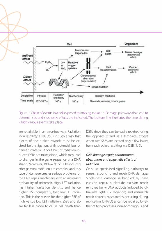
48
critical lesion is the DSB, because it leads to a disruption of the DNA molecule . Most spon-taneous DSBs are products of enzymatic ac-tivity and are regarded as “clean” in that they
Figure 1: Chain of events in a cell exposed to ionising radiation . Damage pathways that lead to deterministic and stochastic effects are indicated . The bottom line illustrates the time during which various events take place
are repairable in an error-free way . Radiation induces “dirty” DNA DSBs in such a way that pieces of the broken strands must be ex-cised before ligation, with potential loss of genetic material . About half of radiation-in-duced DSBs are misrejoined, which may lead to changes in the gene sequence of a DNA strand . Moreover, 30%–40% of DSBs induced after gamma radiation are complex and this type of damage creates serious problems for the DNA repair machinery, with an increased probability of misrepair . High LET radiation has higher ionisation density, and hence higher DSB complexity, than low LET radia-tion . This is the reason for the higher RBE of high versus low LET radiation . SSBs and BD are far less prone to cause cell death than
DSBs since they can be easily repaired using the opposite strand as a template, except when two SSBs are located only a few bases from each other, resulting in a DSB [1, 2] .
DNA damage repair, chromosomal aberrations and epigenetic effects of radiationCells use specialised signalling pathways to sense, respond to and repair DNA damage . Single-base damage is handled by base excision repair, nucleotide excision repair removes bulky DNA adducts induced by ul-traviolet light (UV radiation) and mismatch repair corrects mismatches occurring during replication . DNA DSBs can be repaired by ei-ther of two processes, non-homologous end
Chapter 4: Radiobiological Principles
EAN
M
49
joining (NHEJ) or homologous recombina-tion (HR), where NHEJ is suggested to be the primary repair mechanism for the majority of DSBs . NHEJ occurs in all cell cycle phases and joins DNA ends directly; therefore it is re-garded as the more error-prone repair path-way . HR is active during late S/G2 phase only, where it uses the undamaged homologous strand as a template, and thus is an error-free process . The first attempt to repair damage is made by NHEJ, but if it is unsuccessful there is a switch to HR . For example, HR repairs a larger fraction of high LET-induced damage, where NHEJ is impeded by the complexity of the damage . Another factor that promotes the preferential use of HR is location of the DSB in a region of a more condensed, heter-ochromatic structure [3] .
Despite these repair processes, the probabil-ity of damage misrepair increases with dam-age complexity . Short or long sequences of DNA may be deleted, inverted or translocat-ed to another chromosome . Chromosomal aberrations are changes large enough to be visible at the level of chromosomes, which can be visualised by microscopic staining . Radiation induces chromosome-type aber-rations following irradiation in G1, chroma-tid-type aberrations after irradiation in G2 or both after exposure in S phase . Stable aber-rations can persist in the progeny of irradi-ated cells since the chromosomes have ex-changed genetic material without changing their overall structure . Unstable aberrations, exemplified by dicentric chromosomes, in-
volve a markedly changed chromosomal morphology and cells carrying them may di-vide a few times but will eventually die .
Epigenetic changes can also be induced by radiation exposure . These are heritable changes in gene expression that do not al-ter the DNA sequence per se, such as DNA methylation or acetylation/methylation of residues in histone proteins which wrap up the DNA . There is a global decrease in DNA methylation within one day after radiation exposure of normal cells . Mouse data show that epigenetic alterations could be inherited transgenerationally, but this area of research has not yet been thoroughly investigated [4] .
Cell death modes Cells may survive with mutated DNA but still experience delayed cell death . Alternatively, due to the accumulation of several muta-tions or genomic rearrangements, neoplas-tic cell transformation and cancer can arise . Following a high dose of radiation, the DNA damage may exceed a cell type-specific threshold, causing failure to repair damage and promote cell death instead . Death can occur before or after the first post-radiation mitosis; the latter is commonly called mitot-ic catastrophe and is thought to be a domi-nant event after radiation, although only as a pre-process . The mechanism of death is the active, programmed death, termed apopto-sis, or, in cases of high radiation doses and especially lack of oxygen or energy, necrosis . Cells can also go into permanent cell cycle

50
arrest, senescence . Since radiation-induced cell death can occur at different time points after exposure, the most commonly used method of measuring cell survival is to assess the ability of cells to form clones, clonogenic cell survival [1] .
Normal tissue response to radiationThe effects of ionising radiation at the level of tissues and organisms can be divided into deterministic and stochastic events . Deter-ministic effects originate from cell death events . If a high number of irradiated cells die, this will lead to necrosis of the tissue . Hence, deterministic effects show a dose threshold that corresponds to the dose which kills a sufficiently high number of cells for the tissue to break down . The threshold dose depends on the tissue type, but also on the irradiated volume . Moreover, lowering the dose rate, or splitting the dose into fractions, has a sparing effect on deterministic effects . Importantly, deterministic effects show a direct correla-tion between the dose and severity .
Deterministic effects occur in two phases: a prodromal phase and a late, acute phase . Examples of the prodromal phase are skin reddening, vomiting or dizziness . The nature of these reactions is not understood . Follow-ing moderate doses of radiation, prodromal effects disappear after a few days and late effects occur after a time delay which may be months or years . Very high doses of radiation induce consequential late effects, meaning an immediate transfer from prodromal ef-
fects to late effects . The immune system is always triggered by deterministic effects, so extensive damage of organs and tissues is associated with a massive inflammatory response that by itself can be detrimental and potentiate the radiation effect . Follow-ing whole-body exposure this can lead to multi-organ dysfunction syndrome (MODS) .
Stochastic effects originate from cells that survive a dose of radiation with mutated DNA, which, in turn, can lead to neoplastic transformation . They are probabilistic in na-ture in that it is impossible to predict wheth-er a particular cell will carry a mutation or not . Consequently, stochastic effects have no dose threshold . In contrast to deterministic effects, the severity of a radiation-induced neoplasm is independent of the dose . The only relationship between the dose and the effect is the probability of cancer induction . It is important to bear in mind that radia-tion-induced cancers carry no “fingerprint of exposure” . In other words, they cannot be distinguished from cancers induced by other agents . This is the reason why it is generally difficult to estimate the risk of cancer induc-tion by low doses of radiation (below ca . 200 mGy whole-body exposure), where the inci-dence of spontaneous cancers is much high-er than that of radiation-induced cancers [2] .
Tumour tissue response to radiationRadiotherapy and the four RsTumour cells have acquired a number of char-acteristics that distinguish them from normal
Chapter 4: Radiobiological Principles
EAN
M
51
cells . Several of these hallmarks of cancer are relevant for their response to radiation: ability to sustain proliferative signalling, evasion of growth suppressors, resistance of cell death, genome instability and mutations, and tu-mour-promoting inflammation [5] . Different tumour types also display differences in their inherent radiosensitivity, which provide a basis for the choice of radiotherapy among other treatment modalities such as surgery, chemotherapy, targeted therapy and immu-notherapy .
The aim of radiotherapy is to eradicate cancer cells by delivering the prescribed dose of ion-ising radiation to the tumour with minimal damage to surrounding healthy tissues . This is achieved with the help of various physical techniques . At the same time, efficient tu-mour control must take into consideration the radiosensitivity of cancer cells, which may vary even within a single tumour . Hence, clin-ical radiobiology deals with the relationship between a given physical absorbed dose, the resulting biological response and the factors that influence this relationship .
One of these factors is the partial pressure of molecular oxygen inside a cell . Well-oxygen-ated cells are more sensitive to radiation than hypoxic cells because oxygen participates in the indirect effect of radiation (Fig . 1) . Conse-quently, inactivation of hypoxic cells requires a higher dose than inactivation of normoxic cells . Depending on the localisation inside the body and the density of blood vessels,
tumours can have variable levels of oxygen supply . Within a tumour hypoxic cells form populations in areas distant from blood ves-sels . Hypoxic tumours are generally more difficult to cure . The difference in radiosen-sitivity between hypoxic and normoxic cells is particularly strong for low-LET radiation like photons, where the indirect effect of ra-diation dominates . This is one of the reasons why hadron therapy is believed to be most efficient in curing hypoxic tumours . The ratio of doses required to give the same killing ef-fect in normoxic and hypoxic cells is called the oxygen enhancement ratio (OER) [1] .
The time schedule of irradiation has a big impact on the final consequence of patient treatment during radiotherapy . In curative external beam radiotherapy the total dose prescribed to the tumour (usually 50–80 Gy) is divided into multiple smaller fractions of 2 Gy per day . That this form of therapy yields the best curative results with minimal side effects has been established empirically . Bi-ologically, the fractionation method is based on four elementary principles called the 4 Rs of radiotherapy: (1) repair, (2) redistribution, (3) reoxygenation and (4) repopulation . 1: Tumour cells generally proliferate faster than normal cells and thus have less time to repair the DNA damage before they enter mitosis and suffer from mitotic catastrophe . Hence, they are more sensitive to fractionated irradi-ation than normal cells . 2: Radiation induces a cell cycle arrest in the relatively radiosensi-tive G
2 phase of the cell cycle . This leads to
52
a redistribution of the cells in the cell cycle so that each next fraction of radiation hits cells that are blocked in G2, leading to a high level of cell death . 3: As cells become nor-moxic they begin to proliferate and become radiosensitive . 4: In the first line, radiation kills normoxic, proliferating tumour cells . As these die, hypoxic cells move towards blood vessels and become normoxic . This process of reoxygenation needs some time; hence irradiations should not be carried out during weekends [1] .
Radioresistance and cancer stem cellsAnother level of complexity is added when consideration is given to tumour hetero-geneity, which is not directly related to the oxygen status . Not all tumour cells respond equally to radiation, and accumulating evi-dence supports the concept of cancer stem cells (or tumour-initiating cells), which are resistant to radio- and chemotherapy . This subpopulation of cells is believed to be re-sponsible for tumour regrowth as well as metastasis . Suggested mechanisms of can-cer stem cell radioresistance include both intrinsic factors, such as altered DNA damage repair capacity, enhanced reactive oxygen species defence and activated cell survival pathways, and extrinsic factors, e .g . mainte-nance of a hypoxic niche . Radiation could also induce microenvironmental changes through release of growth factors and cyto-kines from cancer-associated fibroblasts and macrophages, which might confer cellular plasticity [6] .
Low and high dose rate in brachytherapyBrachytherapy can be performed at a low dose rate, for example as done in treatment of thyroid cancer with iodine-131 . Here, the high affinity of the thyroid gland for iodine is exploited . Another form of low dose rate brachytherapy is applied in prostate can-cer patients treated with iodine-125 seeds (called permanent brachytherapy) . Seeds are left permanently in the body and irradiation ends when iodine-125 has decayed . As an alternative to seeds, high-activity radioactive sources (iridium-192) can be used in an af-terloading setup that yields a high dose rate . In prostate cancer treatment, the choice be-tween low and high dose rate brachytherapy is based on tumour stage but also on eco-nomic and practical factors [5] .
Irradiation in utero – developmental and teratogenic effects and cancer The embryo and foetus represent the most radiosensitive stages during the lifetime of a human . Various stages of pregnancy demon-strate different specificities with respect to radiation effects . Gametes and the embryo during the preimplantation stage are char-acterised by extreme sensitivity to the lethal effects of radiation . This is described as an “all or nothing effect”: gametes and embryos either die or survive as normal, with a negli-gible level of detrimental effects . The lack of genetic transgenerational effects among the children of Hiroshima and Nagasaki survivors can be explained by this mechanism .
Chapter 4: Radiobiological Principles
EAN
M
53
Radiation exposure of the embryo after it has implanted in the uterus can lead to three types of effects: growth and mental retarda-tion, malformations and cancer . There is little indication for a threshold of dose . Among Hiroshima and Nagasaki survivors, growth re-tardation was evident only when the embryo was exposed before week 16 of pregnancy . Mental retardation occurred predominantly following exposure during weeks 8–15, with a four times lower level of effect between weeks 15 and 25 . Congenital malformations are uncommon among the atomic bomb survivors, but based on animal studies and women exposed to radiation for medical pur-poses it is understood that they are induced only when the embryo is exposed during organogenesis (weeks 3–8 of pregnancy) [1] .
In their famous “Oxford study” from 1954, Al-ice Stewart and co-workers showed for the first time that diagnostic irradiation in utero leads to an increased risk of leukaemia during early childhood [7] . The result expanded data from atomic bomb survivors, among whom a large relative risk of childhood leukaemia (10 cases instead of the expected 1 .6) was observed among teenagers exposed at the age of 0–9 years [8] . The interest in estimating the risk of childhood cancers has increased in recent years because of modern methods of medical radiography such as paediatric com-puted tomography (CT) . Also, questions have been posed as to whether there is a thresh-old of dose and whether chronic irradiation is equally as effective as acute irradiation . In this
context, it is of interest that two large epide-miological studies, published recently, have shown that natural background radiation is a risk factor in childhood leukaemia, with the lowest effect detectable after an accumulat-ed dose to the bone marrow of 5 mGy [9, 10] . Thus, there is ample evidence that exposure to low doses of radiation, both acutely (as in CT scanning) and chronically (as in areas of high natural background radiation), increases the risk of childhood leukaemia . It is import-ant to note that the level of risk estimated in these studies is consistent with predictions of models based upon data from studies of moderate to high doses received after birth at a high dose rate [8] .
Practical application of radiobiology principles The principles of radiological protection are based on biological and medical evidence of radiation effects . The principles are devel-oped by the ICRP based on scientific data that are regularly summarised by the United Nations Scientific Committee on the Effects of Atomic Radiation (UNSCEAR) and the Bi-ological Effects of Ionizing Radiation (BEIR) group of the National Research Council (NRC) of the USA . ICRP publishes recommen-dations which are generally implemented into legal systems of all countries . The latest recommendation was published in 2007 [11] .
The ICRP assumes that no deterministic ef-fects occur in any tissue in the absorbed dose range up to around 100 mGy (low LET or high
54
LET) . In the case of stochastic effects, notably cancer, epidemiological and experimental studies provide evidence of radiation risk at doses below 100 mSv (effective dose, see be-low) . At the same time, results of biological experiments on cells and animals support the hypothesis that cancer can arise from a DNA mutation in a single cell . Consequently, no dose threshold exists for stochastic effects and the ICRP assumes that even at doses below about 100 mSv a given increment in dose will produce a directly proportionate increment in the probability of incurring can-cer . This dose-response model is generally known as “linear non-threshold” or LNT . The ICRP emphasises that whilst the LNT model remains a scientifically plausible element in its practical system of radiological protection, its adoption is to a large extent guided by the requirement to follow the precautionary principle which is generally applied in health protection .
An important dose concept in radiological protection is the effective dose, which is used for optimising planned radiation exposures . It is calculated based on radiation and tissue weighing factors . The latter are derived from epidemiological results describing the risk of organ-specific cancers following exposure to radiation . The major source of information is the Life Span Study (LSS) on atomic bomb survivors in Hiroshima and Nagasaki . The ear-ly evidence was based on cancer mortality data . Thanks to an improved cancer registry system in Japan, current risk estimate can be
based on cancer incidence, providing more reliable estimates of risk principally because cancer incidence can allow for more accurate diagnosis .
The atomic bomb survivors were exposed to an acute dose of radiation and statistical-ly significant results on cancer induction are seen only after doses in excess of 200 mSv . However, the nominal risk coefficients for stochastic effects derived from the LSS study are used to predict cancer incidence follow-ing occupational or environmental exposure, which is generally low and chronic . For de-terministic effects it is known that reducing the dose rate of radiation is associated with a sparing effect . The question arises as to whether the risk coefficients derived from the LSS study should be lowered when they are being applied to low, chronic exposure scenarios . Based on the results of biological experiments, the ICRP decided to introduce a dose and dose rate effectiveness factor (DDREF) of 2, which reduces by half the nominal risk coefficients when applied to low and chronic exposure scenarios . Due to lack of statistical power, current results from epidemiological studies on cohorts environ-mentally or occupationally exposed to low dose rate radiation do not permit a precise estimate of DDREF . Currently, the value of 2 for DDREF is being debated and a task group of the ICRP is critically evaluating all available evidence in an attempt to come up with a more reliable value [12] .
Chapter 4: Radiobiological Principles
EAN
M
55
References
1 . Hall EJ, Giaccia AJ . Radiobiology for the radiologist . 7th ed . Philadelphia, Baltimore, New York: Lippincott Wil-liams & Wilkins Publishers; 2012 .
2 . Wojcik A, Martin CJ . Biological effects of ionizing radi-ation . In: Martin CJ, Sutton DG, eds . Practical radiation protection . Oxford: Oxford University Press; 2015:21–38 .
3 . Kakarougkas A, Jeggo PA . DNA DSB repair pathway choice: an orchestrated handover mechanism . Br J Ra-diol 2014;87:20130685 .
4 . Zielske SP . Epigenetic DNA methylation in radiation bi-ology: on the field or on the sidelines? J Cell Biochem 2015;116:212–217 .
5 . Skowronek J . Low-dose-rate or high-dose-rate brachytherapy in treatment of prostate cancer – be-tween options . J Contemp Brachytherapy 2013;5:33–41 .
6 . Lundholm L, Haag P, Zong D, Juntti T, Mork B, Lewen-sohn R, Viktorsson K . Resistance to DNA-damaging treatment in non-small cell lung cancer tumor-initiat-ing cells involves reduced DNA-PK/ATM activation and diminished cell cycle arrest . Cell Death Dis 2013;4:e478 .
7 . Stewart A, Webb J, Giles D, Hewitt D . Malignant disease in childhood and diagnostic irradiation in utero . Lancet 1956;271:447 .
8 . Wakeford R . The risk of childhood leukaemia following exposure to ionising radiation – a review . J Radiol Pro-tect 2013;33:1–25 .
9 . Kendall GM, Little MP, Wakeford R, Bunch KJ, Miles JC, Vincent TJ, et al . A record-based case-control study of natural background radiation and the incidence of childhood leukaemia and other cancers in Great Britain during 1980-2006 . Leukemia 2013;27:3–9 .
10 . Spycher BD, Lupatsch JE, Zwahlen M, Roosli M, Niggli F, Grotzer MA, et al . Background ionizing radiation and the risk of childhood cancer: a census-based nationwide co-hort study . Environ Health Perspect 2015;123:622–628 .
11 . ICRP 103 . 2007 recommendations of the Internation-al Commission on Radiological Protection . Ann ICRP 2007;21 .
12 . Ruhm W, Woloschak GE, Shore RE, Azizova TV, Grosche B, Niwa O, et al . Dose and dose-rate effects of ionizing radiation: a discussion in the light of radiological protec-tion . Radiat Environ Biophys 2015;54:379–401 .
56
Chapter 5: Dose Optimisation for Diagnostic ProceduresFrederic H . Fahey, Alison B . Goodkind and David Gilmore
Introduction The fields of nuclear medicine and molecular imaging continue to grow due to the abili-ty of the employed procedures to provide physicians with unique information . Specifi-cally, these procedures provide insights into patients’ physiology and metabolic process-es rather than information on anatomy and structure, as delivered by other imaging mo-dalities . Because disease functional chang-es typically are visible before anatomical changes, nuclear medicine can allow for ear-ly detection and evaluation of the extent of disease; it can also establish whether or not disease is progressing and assist in evaluat-ing the effectiveness of a given treatment . Nuclear medicine methodologies reveal in-formation about nearly all human systems, including the heart and the brain as well as the musculoskeletal, gastrointestinal and urological systems . Nuclear medicine can also be essential for imaging various types of cancer . In addition, these modalities are min-imally invasive and safe as they utilise only trace amounts of radiopharmaceuticals and, thus, are non-toxic and non-allergenic [1] . Not only is nuclear medicine often essential for diagnosis, but it can also play an import-ant role in the treatment of many diseases, an example being the administration of 131I for the treatment of thyroid disease . More recently, targeted radionuclide therapy has been shown to be useful in the treatment of bone metastases from prostate cancer and neuroendocrine tumours .
According to the National Council on Radi-ation Protection and Measurements (NCRP) Report 160, nuclear medicine procedures have increased from 6 .3 million in 1984 to 18 million in 2006 [2] . This increase has led to a rise in per capita annual radiation dose to the US population from nuclear medicine pro-cedures . In 2006, the per capita annual dose to the US population from nuclear medicine was estimated to be 0 .8 mSv compared to 0 .14 mSv in 1982, with a large fraction of this dose attributed to nuclear cardiology .
This increase in the utilisation of nuclear med-icine procedures has led to an increase in ion-ising radiation exposure and thus the possible risk of adverse health effects . Bearing in mind that concerns regarding these risks have been expressed by the media and the general pub-lic, the nuclear medicine professional needs to have a solid understanding of their nature and magnitude, as well as of the factors that can affect the radiation dose to our patients and ourselves . Having this understanding will allow us to better communicate with patients regarding the potential benefits and risks as-sociated with nuclear medicine procedures . This can be essential for the patient’s health . If a procedure providing important clinical in-formation is not performed due to fear of radi-ation, it can be detrimental to the patient . This chapter will discuss dose optimisation, which considers the potential risk from undergoing a nuclear medicine procedure, as well as the many benefits that these imaging modalities have to offer patients . Ultimately, performing
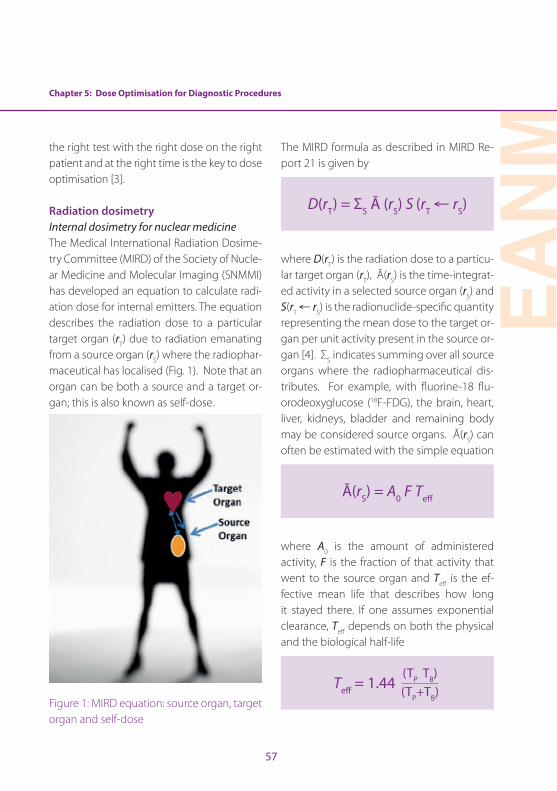
EAN
M
57
Chapter 5: Dose Optimisation for Diagnostic Procedures
the right test with the right dose on the right patient and at the right time is the key to dose optimisation [3] .
Radiation dosimetryInternal dosimetry for nuclear medicineThe Medical International Radiation Dosime-try Committee (MIRD) of the Society of Nucle-ar Medicine and Molecular Imaging (SNMMI) has developed an equation to calculate radi-ation dose for internal emitters . The equation describes the radiation dose to a particular target organ (rT) due to radiation emanating from a source organ (rS) where the radiophar-maceutical has localised (Fig . 1) . Note that an organ can be both a source and a target or-gan; this is also known as self-dose .
Figure 1: MIRD equation: source organ, target organ and self-dose
The MIRD formula as described in MIRD Re-port 21 is given by
D(rT) = ΣS Ã (rS) S (rT ← rS)
where D(rT) is the radiation dose to a particu-lar target organ (rT), Ã(rS) is the time-integrat-ed activity in a selected source organ (rS) and S(rT ← rS) is the radionuclide-specific quantity representing the mean dose to the target or-gan per unit activity present in the source or-gan [4] . ΣS indicates summing over all source organs where the radiopharmaceutical dis-tributes . For example, with fluorine-18 flu-orodeoxyglucose (18F-FDG), the brain, heart, liver, kidneys, bladder and remaining body may be considered source organs . Ã(rS) can often be estimated with the simple equation
Ã(rS) = A0 F Teff
where A0 is the amount of administered activity, F is the fraction of that activity that went to the source organ and Teff is the ef-fective mean life that describes how long it stayed there . If one assumes exponential clearance, Teff depends on both the physical and the biological half-life
Teff = 1.44 (TP TB)(TP+TB)
58
where TP and TB are the physical and biolog-ical half-lives for the particular radiopharma-ceutical and source organ . S(rT ← rS) is given by
S(rT ← rS) = Σi Δi φi/MT
where Δi is the mean energy per nuclear transformation for the ith radiation emitted by the radiopharmaceutical, φi is the fraction of energy emitted by the ith radiation from the source organ that is absorbed by the target organ and MT is the mass of the target organ . Σi indicates summing over all radiations, i, emitted from the radiopharmaceutical .
As one can see from the above formulas, the estimated dose depends on many fac-tors . Most notably, it depends directly on the amount of administered activity . With re-spect to internal dosimetry, this is the prima-ry dose index . Radiation dose also depends on the type and energy of the radiation [penetrating (gamma rays) versus non-pen-etrating (alphas/betas/positrons)] emitted by the associated radionuclide, the size, shape and composition of the source and target organ(s), the spacing between the source and target organ(s) and the type of material separating them, as well as on the energy ab-sorbed from ionising radiation per unit time within the source and target organ(s) . Models of patients of different sizes, from newborns to adults as well as pregnant women, have
been developed and adopted by a number of organisations such as the European As-sociation of Nuclear Medicine (EANM), the SNMMI and the International Commission on Radiation Protection (ICRP) . Thus, if one knows the amount of administered activity, the size of the patient and the biokinetics and physical properties of the radiopharma-ceutical in question, one can make a reason-able estimate of the radiation dose to all of the potential target organs . However, it has been estimated that the uncertainty in these estimates could be as much as a factor of 2 [5] .
The concept of effective dose (ED) was pro-posed by the ICRP to provide a risk-based parameter to allow different radiological practices to be compared . Effective dose was developed to be equivalent to the absorbed dose given to the whole body of the patient that would result in the same biological ef-fect . It is the weighted sum of the absorbed dose delivered to each target organ with each organ weighted by its radiation sensi-tivity . The formula is
ED = Σ HT × WT
where HT is dose to organ, T, and WT is the radiosensitivity weight assigned to that organ . Effective dose is based on a popu-lation-based estimate of radiation risk and does not apply to a specific patient (Table 1) . It should be noted that the risk-based organ

Chapter 5: Dose Optimisation for Diagnostic Procedures
EAN
M
59
weights are based on population averages across all ages and both genders and thus are not directly applicable to any individual patient . In particular, they do not reflect the higher risks associated with young children, as discussed in the next section .
Tissue or Organ ICRP 103
Gonads 0 .08
Red bone marrow 0 .12
Lung 0 .12
Colon 0 .12
Stomach 0 .12
Breast 0 .12
Bladder 0 .04
Liver 0 .04
Oesophagus 0 .04
Thyroid 0 .04
Skin 0 .01
Bone surface 0 .01
Brain 0 .01
Salivary glands 0 .01
Remainder 0 .12
Total 1 .00
Table 1: List of weights for effective dose (adapted from ICRP Report 103)
The ICRP has published standardised dose es-timates for many radiopharmaceuticals . This extensive set of dose estimates represents the best available understanding of the bio-
kinetics of the compounds [6] . Although the tabulated calculations from the ICRP calcula-tions include absorbed and effective doses to children, the biokinetic models used in these calculations are typically derived from adult data . Thus, the applicability of these models to children has not yet been ascertained . The UF phantom sets from the University of Florida provide anthropomorphic models of patients of a variety of sizes and shapes [7] . Another resource for dose estimation is the RADAR website, which also has data on stan-dardised dose methods, models and results . It is important to note that the effective dose is based on a population-based estimate of radiation risk and does not apply to a specific patient .
The primary factor affecting the radiation dose to the nuclear medicine patient is administered activity, as discussed above . However, there are many issues that can be considered when determining the optimal level of administered activity, including the patient size, the imaging time and the type of instrumentation used . The standardisa-tion of administered activities in children will be described in a subsequent section . For planar nuclear medicine and SPECT, factors regarding instrumentation may include the thickness and composition of the detector material, as well as the number of detectors . Another factor that contributes to dose is the choice of collimator (i .e . whether to use pinhole, ultra-high-resolution, high-reso-lution, general purpose or high-sensitivity
60
collimation) . With respect to PET, the design, composition and configuration of the detec-tor material comes into play . The diameter and axial extent of the detectors also affect the scanner sensitivity . One may also consid-er the effect that new approaches to image processing and tomographic reconstruction may have on image quality and their po-tential impact on dose reduction . Recent reports have indicated that the application of adaptive filtering or iterative reconstruc-tion with resolution recovery may allow for a dose reduction of a factor of 2 or more while maintaining or perhaps even improving im-age quality [8–11] .
There is limited information regarding the ac-tual practice of nuclear medicine procedures . Based on surveys of practice, diagnostic ref-erence levels may be developed to serve as guidelines to the clinical practitioner . In some instances, these levels may be regulat-ed to represent acceptable practice . At this point, very little survey data regarding nucle-ar medicine practice is available in the liter-ature . The SNMMI Dose Opt Task Force and the Intersociety Accreditation Commission (IAC) partnered to look at nuclear medicine practice data within the United States . The IAC provided data that had been submitted to them as part of the accreditation process . For technetium-99m methylene diphospho-nate (MDP) bone scans, data from 225 sites and 522 total patient studies were analysed . For 18F-FDG PET, 95 sites and 424 total pa-tients were analysed . The mean administered
activity was 930±118 (range 710–1315) MBq for 99mTc-MDP and 508±117 (range 108–875) MBq for 18F-FDG . There was no difference in administered activity according to the type of site (hospital, private, free-standing and multispecialty, mobile); although mo-bile units appeared to be associated with a higher activity, information was available for only a limited number of sites in both cases (n=1 and n=3 for 99mTc-MDP and 18F-FDG, re-spectively) . These data show that although a large percentage of the sites are reasonably consistent with regard to their administered activities, a wide variation still remains (Fig . 2) [12] .
Hybrid imagingPET/CT imaging using a single, hybrid device was introduced commercially around the turn of the century and its clinical impact was recognised immediately . Within 5 years of its introduction, PET-only devices were no lon-ger being marketed . The combination of the functional/molecular information provided by PET and with the anatomical information provide by CT were deemed invaluable by the clinician . A few years later, SPECT/CT was introduced . Although SPECT/CT has been shown to be valuable for a number of spe-cific clinical applications, its application has not been as widespread as that of PET/CT . The CT component of both PET and SPECT involves the use of X-rays that also expose the patient to ionising radiation, which is dis-cussed in this book . However, the total radi-ation dose to the patient is the sum of that
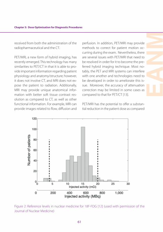
Chapter 5: Dose Optimisation for Diagnostic Procedures
EAN
M
61
received from both the administration of the radiopharmaceutical and the CT .
PET/MRI, a new form of hybrid imaging, has recently emerged . This technology has many similarities to PET/CT in that it is able to pro-vide important information regarding patient physiology and anatomy/structure; however, it does not involve CT, and MRI does not ex-pose the patient to radiation . Additionally, MRI may provide unique anatomical infor-mation with better soft tissue contrast res-olution as compared to CT, as well as other functional information . For example, MRI can provide images related to flow, diffusion and
perfusion . In addition, PET/MRI may provide methods to correct for patient motion oc-curring during the exam . Nevertheless, there are several issues with PET/MRI that need to be resolved in order for it to become the pre-ferred hybrid imaging technique . Most no-tably, the PET and MRI systems can interfere with one another and technologies need to be developed in order to ameliorate this is-sue . Moreover, the accuracy of attenuation correction may be limited in some cases as compared to that for PET/CT [13] .
PET/MRI has the potential to offer a substan-tial reduction in the patient dose as compared
Figure 2: Reference levels in nuclear medicine for 18F-FDG [12] (used with permission of the Journal of Nuclear Medicine)
62
to PET/CT beyond the elimination of the CT component . Utilising the SIGNA PET/MR, a time-of-flight (TOF) PET/MRI scanner, Queiroz et al . examined both phantom and clinical data . By increasing the PET axial FOV (25 vs 15 cm) and decreasing the PET ring diameter (622 vs 810 cm), the authors determined that PET/MRI could be performed with half of the administered activity [14] . It has also been shown that adopting the longer acquisition time associated with MRI for the PET scan can improve dose optimisation . Oehmigen et al . imaged a standardised phantom to compare the dose from PET/MRI under various time constraints (2, 4, 8 and 16 min) [15] . Ultimate-ly, they discovered that they could reduce ra-diotracer activity by compensating for longer imaging times . These findings could lead to a large decrease in dose amongst patients, while maintaining imaging quality . Specifical-ly, the effective dose for an FDG PET/CT scan is approximately 12–22 mSv; however, using PET/MRI, the effective dose could be as low as 1 .8 mSv . These quantities illustrate a potential for dose reduction of administered activity by a factor of 4–8 .
Radiation riskEstimation of the risk of adverse health ef-fects from exposure to ionising radiation in the dose range commonly encountered in clinical nuclear medicine involves the appli-cation of models based on the most current knowledge of pertinent epidemiological and biological data . However, these scientific data were acquired in a situation quite dissimilar
to clinical nuclear medicine, and one there-fore needs to extrapolate to the condition of interest . This may involve the extrapolation of high-dose data in humans or low-dose data in animals to low-dose (below 100 mSv) ef-fects in humans . Our basic understanding of the effects of exposure to ionising radiation on human health derives from the Life Span Study of the survivors of the bombings of Hi-roshima and Nagasaki, as reported by the Ra-diation Effects Research Foundation . In 2011, Ozasa et al published a review of these data . In this study, 86,600 subjects had been fol-lowed from 1950 to 2003, and it was estimat-ed that there had been 527 excess deaths from solid tumours in that population [16] . Other epidemiological studies have evalu-ated the risk of ionising radiation in humans, and, in general, their results corroborate the findings of the Life Span Study . Data from the Life Span Study clearly indicate a relationship between induction of solid cancer and ra-diation dose at levels >0 .5 Gy . However, un-certainties in the data make it difficult to es-timate the risk at the dose range associated with clinical nuclear medicine (i .e . 0 .05–0 .1 Gy) . Differences in dose rate or the fraction-ation of dose between the epidemiological subjects and nuclear medicine patients can also affect the accuracy of the estimation . For these reasons, the evaluation of findings from investigations in radiobiology can often provide valuable insights .
The National Academy of Sciences Com-mittee on the Biological Effects of Ionizing

Chapter 5: Dose Optimisation for Diagnostic Procedures
EAN
M
63
Radiation (BEIR) issued a report in 2006 that reviewed the state of knowledge in radia-tion epidemiology and biology at that time and developed models of radiation risk as a function of dose, sex and age at the time of exposure . This review was published in what is referred to as the BEIR VII Phase 2 re-port [17] . This report recommended a linear no-threshold model for cancer induction by ionising radiation in solid tumours and a linear quadratic model for leukaemia . Al-though some controversies exist regarding the scientific validity of the linear no-thresh-old model for estimating radiation risk at low doses, it may be considered a conservative and thereby prudent model for radiation safety purposes . According to the mod-els provided by the BEIR VII Phase 2 report, those exposed at an earlier age are in gen-eral at higher risk for cancer induction from ionising radiation than adults .
Cardiovascular nuclear medicineThe utilisation of myocardial perfusion im-aging (MPI) using radiopharmaceuticals has increased substantially over the past 30 years, such that it has become an essential component of the armamentarium available to assess patients for the risk of a significant myocardial event [18, 19] . In 2006, it was es-timated that nuclear cardiology accounted for 57% of the nuclear medicine procedures performed in the United States [2] . These studies are typically performed as a rest study followed by a stress study, resulting in an effective dose when using 99mTc-sestamibi
of between 10 and 13 mSv, depending on the actual administered activities . Therefore, nuclear cardiology accounts for about 85% of the total collective radiation dose from nu-clear medicine in the United States . On the other hand, more than half of the patients receiving radionuclide myocardial perfusion studies are over the age of 65 years and at lower risk of adverse effects from radiation than younger individuals .
Since nuclear cardiology is the most common nuclear medicine procedure and accounts for the largest contribution to the nuclear medicine collective dose, there have been a number of discussions regarding dose opti-misation in this arena [20–22] . In 2011, the Cardiovascular Council of the SNMMI issued a position paper [23] stating that “…radionu-clide MPI can provide scientifically validated, accurate, and in certain cases unique infor-mation for management of patients with known or suspected coronary artery disease at risk for major cardiovascular events . The radiation exposure risk associated with radio-nuclide MPI, albeit small and long term as op-posed to the higher and more immediate risk for major cardiovascular events, mandates careful adherence to appropriateness criteria and guidelines developed or endorsed by the Society of Nuclear Medicine, the Ameri-can Society of Nuclear Cardiology, the Amer-ican College of Cardiology and the American Heart Association . With recent developments in technology, there are many opportunities to further reduce radiation exposure and fur-
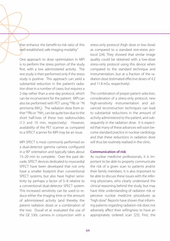
64
ther enhance the benefit-to-risk ratio of this well-established, safe imaging modality .”
One approach to dose optimisation in MPI is to perform the stress portion of the study first, with a low administered activity . The rest study is then performed only if the stress study is positive . This approach can yield a substantial reduction in the patient’s radia-tion dose in a number of cases, but requires a 2-day rather than a one-day protocol, which can be inconvenient for the patient . MPI can also be performed with PET using 82Rb or 13N ammonia (NH3) . The radiation dose from ei-ther 82Rb or 13NH3 can be quite low due to the short half-lives of these two radionuclides (1 .3 and 10 min, respectively) . However, availability of the PET scanner as compared to a SPECT scanner for MPI may be an issue .
MPI SPECT is most commonly performed on a dual-detector gamma camera configured in a 90° orientation and typically takes about 15–20 min to complete . Over the past de-cade, SPECT devices dedicated to myocardial SPECT have been developed that not only have a smaller footprint than conventional SPECT systems, but also have higher sensi-tivity by perhaps a factor of 5–8 relative to a conventional dual-detector SPECT system . This increased sensitivity can be used to re-duce either the imaging time or the amount of administered activity (and thereby the patient radiation dose) or a combination of the two . Duvall et al . evaluated the use of the GE 530c camera in conjunction with a
stress-only protocol (high dose or low dose) as compared to a standard rest-stress pro-tocol [24] . They showed that similar image quality could be obtained with a low-dose stress-only protocol using this device when compared to the standard technique and instrumentation, but at a fraction of the ra-diation dose (estimated effective doses of 4 .2 and 11 .8 mSv, respectively) .
The combination of proper patient selection, consideration of a stress-only protocol, new high-sensitivity instrumentation and ad-vanced reconstruction techniques can lead to substantial reductions in the amount of activity administered to the patient, and sub-sequently in the radiation dose . It is expect-ed that many of these advances will soon be-come standard practice in nuclear cardiology and that these reductions in radiation dose will thus be routinely realised in the clinic .
Communication of riskAs nuclear medicine professionals, it is im-portant to be able to properly communicate the risk of a given scan to patients and/or their family members . It is also important to be able to discuss these issues with the refer-ring physicians, who clearly understand the clinical reasoning behind the study, but may have little understanding of radiation risk or perceive nuclear medicine procedures as “high dose” . Reports have shown that inform-ing patients regarding radiation risk does not adversely affect their willingness to have an appropriately ordered scan [25] . First, the
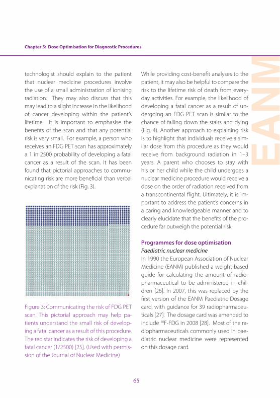
Chapter 5: Dose Optimisation for Diagnostic Procedures
EAN
M
65
technologist should explain to the patient that nuclear medicine procedures involve the use of a small administration of ionising radiation . They may also discuss that this may lead to a slight increase in the likelihood of cancer developing within the patient’s lifetime . It is important to emphasise the benefits of the scan and that any potential risk is very small . For example, a person who receives an FDG PET scan has approximately a 1 in 2500 probability of developing a fatal cancer as a result of the scan . It has been found that pictorial approaches to commu-nicating risk are more beneficial than verbal explanation of the risk (Fig . 3) .
Figure 3: Communicating the risk of FDG PET scan . This pictorial approach may help pa-tients understand the small risk of develop-ing a fatal cancer as a result of this procedure . The red star indicates the risk of developing a fatal cancer (1/2500) [25] . (Used with permis-sion of the Journal of Nuclear Medicine)
While providing cost-benefit analyses to the patient, it may also be helpful to compare the risk to the lifetime risk of death from every-day activities . For example, the likelihood of developing a fatal cancer as a result of un-dergoing an FDG PET scan is similar to the chance of falling down the stairs and dying (Fig . 4) . Another approach to explaining risk is to highlight that individuals receive a sim-ilar dose from this procedure as they would receive from background radiation in 1–3 years . A parent who chooses to stay with his or her child while the child undergoes a nuclear medicine procedure would receive a dose on the order of radiation received from a transcontinental flight . Ultimately, it is im-portant to address the patient’s concerns in a caring and knowledgeable manner and to clearly elucidate that the benefits of the pro-cedure far outweigh the potential risk .
Programmes for dose optimisationPaediatric nuclear medicineIn 1990 the European Association of Nuclear Medicine (EANM) published a weight-based guide for calculating the amount of radio-pharmaceutical to be administered in chil-dren [26] . In 2007, this was replaced by the first version of the EANM Paediatric Dosage card, with guidance for 39 radiopharmaceu-ticals [27] . The dosage card was amended to include 18F-FDG in 2008 [28] . Most of the ra-diopharmaceuticals commonly used in pae-diatric nuclear medicine were represented on this dosage card .
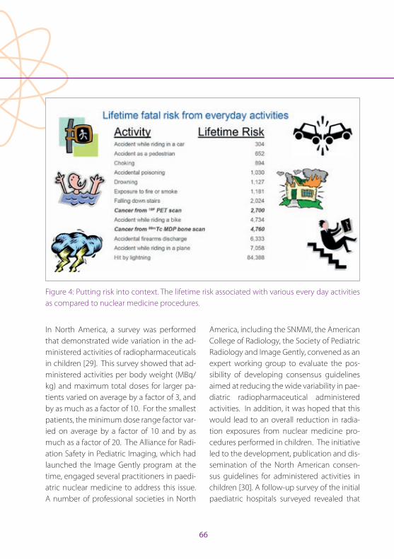
66
In North America, a survey was performed that demonstrated wide variation in the ad-ministered activities of radiopharmaceuticals in children [29] . This survey showed that ad-ministered activities per body weight (MBq/kg) and maximum total doses for larger pa-tients varied on average by a factor of 3, and by as much as a factor of 10 . For the smallest patients, the minimum dose range factor var-ied on average by a factor of 10 and by as much as a factor of 20 . The Alliance for Radi-ation Safety in Pediatric Imaging, which had launched the Image Gently program at the time, engaged several practitioners in paedi-atric nuclear medicine to address this issue . A number of professional societies in North
America, including the SNMMI, the American College of Radiology, the Society of Pediatric Radiology and Image Gently, convened as an expert working group to evaluate the pos-sibility of developing consensus guidelines aimed at reducing the wide variability in pae-diatric radiopharmaceutical administered activities . In addition, it was hoped that this would lead to an overall reduction in radia-tion exposures from nuclear medicine pro-cedures performed in children . The initiative led to the development, publication and dis-semination of the North American consen-sus guidelines for administered activities in children [30] . A follow-up survey of the initial paediatric hospitals surveyed revealed that
Figure 4: Putting risk into context . The lifetime risk associated with various every day activities as compared to nuclear medicine procedures .
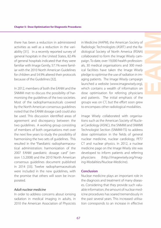
Chapter 5: Dose Optimisation for Diagnostic Procedures
EAN
M
67
there has been a reduction in administered activities as well as a reduction in the vari-ability [31] . In a recently reported survey of general hospitals in the United States, 82 .4% of general hospitals indicated that they were familiar with Image Gently, 57 .1% were famil-iar with the 2010 North American Guidelines for children and 54 .9% altered their protocols because of the Guidelines [32] .
In 2012, members of both the EANM and the SNMMI met to discuss the possibility of har-monising the guidelines of the two societies . Most of the radiopharmaceuticals covered by the North American consensus guidelines noted that the EANM dosage card could also be used . This discussion identified areas of agreement and discrepancy between the two guidelines . A working group consisting of members of both organisations met over the next few years to study the possibility of harmonising the two sets of guidelines . This resulted in the “Paediatric radiopharmaceu-tical administration: harmonization of the 2007 EANM paediatric dosage card” (ver-sion 1 .5 .2008) and the 2010 North American consensus guidelines document published in 2014 [33] . Twelve radiopharmaceuticals were included in the new guidelines, with the promise that others will soon be incor-porated .
Adult nuclear medicineIn order to address concerns about ionising radiation in medical imaging in adults, in 2010 the American Association of Physicists
in Medicine (AAPM), the American Society of Radiologic Technologists (ASRT) and the Ra-diological Society of North America (RSNA) collaborated to form the Image Wisely cam-paign . To date, over 19,000 health profession-als, 30 medical organisations and 300 med-ical facilities have taken the Image Wisely pledge to optimise the use of radiation in im-aging patients . The Image Wisely campaign launched a website (www .imagewisely .org), which contains a wealth of information on dose optimisation for referring physicians and patients . The initial emphasis of the groups was on CT, but the effort soon grew to encompass other radiological modalities .
Image Wisely collaborated with organisa-tions such as the American Society of Nucle-ar Cardiology (ASNC), the SNMMI and SNMMI Technologist Section (SNMMI-TS) to address dose optimisation in the fields of general nuclear medicine, nuclear cardiology, PET/CT and nuclear physics . In 2012, a nuclear medicine page on the Image Wisely site was developed to inform patients and referring physicians (http://imagewisely .org/Imag-ing-Modalities/Nuclear-Medicine) .
ConclusionNuclear medicine plays an important role in the diagnosis and treatment of many diseas-es . Considering that they provide such valu-able information, the amount of nuclear med-icine procedures has soared tremendously in the past several years . This increased utilisa-tion corresponds to an increase in effective

68
dose amongst the world population . As a nu-clear medicine technologist it is important to understand the risk of such procedures and how to communicate the benefits as well as the potential harm from these procedures to patients, family members and attending phy-sicians . Having an understanding of internal dosimetry for PET, SPECT, PET/CT, SPECT/CT and PET/MRI, as well as a comprehension of how the appropriate dose is determined, will help to minimise risk and maximise the many benefits of nuclear medicine .
Chapter 5: Dose Optimisation for Diagnostic Procedures
EAN
M
69
References
1 . Fahey F, Treves ST, Lassmann M . Dose optimization in pediatric nuclear medicine . Clinical and Translational Imaging 2016;4:5–11 .
2 . Schauer DA, Linton OW . NCRP report No . 160 . Ioniz-ing radiation exposure of the population of the Unit-ed States, medical exposure—are we doing less with more, and is there a role for health physicists? Health Phys 2009;97:1–5 .
3 . Treves ST, Falone AE, Fahey FH . Pediatric nuclear medi-cine and radiation dose . Semin Nucl Med 2014;44:202–209 .
4 . Bolch WE, Eckerman KF, Sgouros G, Thomas SR . MIRD pamphlet no . 21: a generalized schema for radiophar-maceutical dosimetry—standardization of nomencla-ture . J Nucl Med 2009;50:477–484 .
5 . Stabin MG . Uncertainties in internal dose calculations for radiopharmaceuticals . J Nucl Med 2008;49:853–860 .
6 . Mattsson S, Johansson L, Svegborn SL, Liniecki J, Noßke D, Riklund K, et al . ICRP Publication 128: Radiation dose to patients from radiopharmaceuticals: a compendium of current information related to frequently used sub-stances . Ann ICRP 2015;44(2 suppl):7–321 .
7 . O’Reilly SE, Plyku D, Sgouros G, Fahey FH, Ted TS, Frey EC, et al . A risk index for pediatric patients undergoing diagnostic imaging with (99m) Tc-dimercaptosuccin-ic acid that accounts for body habitus . Phys Med Biol 2016;61:2319–2332 .
8 . Fahey F, Zukotynski K, Zurakowski D, Markelewicz R, Falone A, Vitello M, et al . Beyond current guidelines: reduction in minimum administered radiopharmaceu-tical activity with preserved diagnostic image quality in pediatric hepatobiliary scintigraphy . Eur J Nucl Med Mol Imaging 2014;41:2346–2353 .
9 . Hsiao EM, Cao X, Zurakowski D, Zukotynski KA, Drubach LA, Grant FD, et al . Reduction in radiation dose in mer-captoacetyltriglycerine renography with enhanced planar processing . Radiology 2011;261:907–915 .
10 . Stansfield EC, Sheehy N, Zurakowski D, Vija AH, Fahey FH, Treves ST . Pediatric 99mTc-MDP bone SPECT with ordered subset expectation maximization iterative reconstruction with isotropic 3D resolution recovery . Radiology 2010;257:793–801 .
11 . Sheehy N, Tetrault TA, Zurakowski D, Vija AH, Fahey FH, Treves ST . Pediatric 99mTc-DMSA SPECT performed by using iterative reconstruction with isotropic resolution recovery: improved image quality and reduced radio-pharmaceutical activity . Radiology 2009;251:511–516 .
12 . Alessio AM, Farrell MB, Fahey FH . Role of reference levels in nuclear medicine: a report of the SNMMI Dose Op-timization Task Force . J Nucl Med 2015;56:1960–1964 .
13 . Bolus NE, George R, Newcomer BR . PET/MRI: the blend-ed-modality choice of the future? J Nucl Med Technol 2009;37:63–71 .
14 . Queiroz MA, Delso G, Wollenweber S, Deller T, Zeimpekis K, Huellner M, et al . Dose optimization in TOF-PET/MR compared to TOF-PET/CT . PloS One 2015;10:e0128842 .
15 . Oehmigen M, Ziegler S, Jakoby BW, Georgi J-C, Paulus DH, Quick HH . Radiotracer dose reduction in integrated PET/MR: implications from National Electrical Manu-facturers Association phantom studies . J Nucl Med 2014;55:1361–1367 .
16 . Ozasa K, Shimizu Y, Suyama A, Kasagi F, Soda M, Grant EJ, et al . Studies of the mortality of atomic bomb survivors, Report 14, 1950-2003: an overview of cancer and non-cancer diseases . Radiat Res 2011;177:229–243 .
17 . National Research Council (US) Board on Radiation Ef-fects Research . Health risks from exposure to low levels of ionizing radiation: Beir VII phase II . Washington (DC): National Academic Press; 2006 .
18 . Berman DS, Shaw LJ, Min JK, Hachamovitch R, Abidov A, Germano G, et al . SPECT/PET myocardial perfusion imaging versus coronary CT angiography in patients with known or suspected CAD . Q J Nucl Med Mol Im-aging 2010;54:177–200 .
70
19 . Hachamovitch R, Berman DS, Shaw LJ, Kiat H, Cohen I, Cabico JA, et al . Incremental prognostic value of myo-cardial perfusion single photon emission computed tomography for the prediction of cardiac death: differ-ential stratification for risk of cardiac death and myocar-dial infarction . Circulation 1998;97:535–543 .
20 . Kaul P, Medvedev S, Hohmann SF, Douglas PS, Peterson ED, Patel MR . Ionizing radiation exposure to patients admitted with acute myocardial infarction in the United States . Circulation 2010;122:2160–2169 .
21 . Small GR, Chow BJ, Ruddy TD . Low-dose cardiac imag-ing: reducing exposure but not accuracy . Expert Rev Cardiovasc Ther 2012;10:89–104 .
22 . Small GR, Wells RG, Schindler T, Chow BJ, Ruddy TD . Ad-vances in cardiac SPECT and PET imaging: overcoming the challenges to reduce radiation exposure and im-prove accuracy . Can J Cardiol 2013;29:275–284 .
23 . Sadeghi MM, Schwartz RG, Beanlands RS, Al-Mallah MH, Bengel FM, Borges-Neto S, et al . Cardiovascular nuclear imaging . J Nucl Med 2011;52:1162–1164 .
24 . Duvall WL, Croft LB, Godiwala T, Ginsberg E, George T, Henzlova MJ . Reduced isotope dose with rapid SPECT MPI imaging: initial experience with a CZT SPECT cam-era . J Nucl Cardiol 2010;17:1009–1014 .
25 . Fahey FH, Treves ST, Adelstein SJ . Minimizing and com-municating radiation risk in pediatric nuclear medicine . J Nucl Med 2011;52:1240–1251 .
26 . Piepsz A, Hahn K, Roca I, Ciofetta G, Toth G, Gordon I, et al . A radiopharmaceuticals schedule for imaging in paediatrics . Paediatric Task Group European Association Nuclear Medicine . Eur J Nucl Med 1990;17:127–129 .
27 . Lassmann M, Biassoni L, Monsieurs M, Franzius C, Jacobs F, Dosimetry E, et al . The new EANM paediatric dosage card . Eur J Nucl Med Mol Imaging 2008;35:1748 .
28 . Lassmann M, Biassoni L, Monsieurs M, Franzius C, Dosim-etry E, Paediatrics C . The new EANM paediatric dosage card: additional notes with respect to F-18 . Eur J Nucl Med Mol Imaging 2008;35:1666–1668 .
29 . Treves ST, Davis RT, Fahey FH . Administered radiophar-maceutical doses in children: a survey of 13 pediatric hospitals in North America . J Nucl Med 2008;49:1024–1027 .
30 . Gelfand MJ, Parisi MT, Treves ST . Pediatric radiophar-maceutical administered doses: 2010 North American consensus guidelines . J Nucl Med 2011;52:318–322 .
31 . Fahey FH, Ziniel SI, Manion D, Treves ST . Effects of Image Gently and the North American guidelines: adminis-tered activities in children at 13 North American pedi-atric hospitals . J Nucl Med 2015;56:962–967 .
32 . Fahey FH, Ziniel SI, Manion D, Baker A, Treves ST . Ad-ministered activities for pediatric nuclear medicine pro-cedures and the impact of the 2010 North American guidelines on general hospitals in the United States . J Nucl Med 2016 57:1478–1485 .
33 . Lassmann M, Treves ST, Group ESPDHW . Paediatric ra-diopharmaceutical administration: harmonization of the 2007 EANM paediatric dosage card (version 1 .5 . 2008) and the 2010 North American consensus guidelines . Eur J Nucl Med Mol Imaging 2014;41:1036–1041 .

EAN
M
71
Chapter 6: Dose Optimisation of CT in Hybrid ImagingFrederic H . Fahey, Elizabeth Romero and Adam Alessio
IntroductionFor the past 15 years, hybrid imaging using CT has been an essential aspect of nuclear medicine imaging . Hybrid PET/CT scanners became commercially available around the turn of the century and by 2005, only 5 years later, PET-only scanners were no longer being marketed by any of the major manufacturers (Fig . 1A) . The combination of the functional and molecular imaging capabilities of PET with the superior anatomical correlation of CT was deemed invaluable by clinicians, par-ticularly in the field of oncology . In addition, the ability to utilise the rapidly acquired and relatively low-noise CT for attenuation correc-tion in lieu of the much slower transmission scan reduced the time required to perform a whole-body PET scan by close to 50% . More recently, SPECT/CT has been clinically estab-lished, particularly for certain medical indica-tions (Fig . 1B) . However, the use of CT expos-es the patient to ionising radiation in addition to that from the administration of the radio-pharmaceutical inherent to nuclear medicine .
As will be discussed, depending on how it is used and thereby how it is acquired, the CT can comprise a small or a considerable frac-tion of the radiation absorbed dose received by the patient . In this chapter, we will review the way CT is typically used in the context of hybrid imaging, how it is acquired, the range of associated radiation doses and approaches to optimise the acquisition in order to obtain the image information necessary to address the clinical question at hand while delivering the lowest possible radiation dose .
Uses of CT in hybrid imagingIn the practice of hybrid imaging, either PET/CT or SPECT/CT, the CT can be acquired and subsequently used for three distinct purpos-es or a combination thereof . In the first case, the CT portion can be used for attenuation correction of the emission scan (i .e . PET or SPECT) since it provides the photon trans-mission information necessary for this pur-pose . If the CT is only used for attenuation correction, the CT acquisition parameters can
Figure 1: PET/CT and SPECT/CT . Illustration of the major PET/CT (A) and SPECT/CT (B) scanner components for conventional designs
A B
72
be substantially reduced without impairing the ability of the CT to provide adequate at-tenuation correction [1] . Secondly, it can be used for anatomical correlation of the PET or SPECT data . In this instance, the CT need not be of diagnostic image quality, but it must be of a sufficient standard to permit correlation with the emission scan based on adequate depiction of the anatomical features of inter-est . Lastly, the CT may be acquired in a man-ner appropriate for a diagnostic CT study of the region of interest . If the patient requires a CT and an emission scan for diagnosis, the ability to acquire both in a single imaging session is not only convenient and efficient for the patient, but also allows dose reduc-tion by potentially eliminating the need for an additional CT scan . In many instances, the CT portion of hybrid imaging may be used for more than one of the above-mentioned purposes . For example, a CT of diagnostic quality may also be used for anatomical cor-relation and attenuation correction or a CT for anatomical correlation may also be used for attenuation correction . These three uses of CT have considerably different require-ments with respect to both the complexity of the image data acquisition and the radia-tion dose delivered to the patient .
The probability of detecting a photon emit-ted from the centre of the patient is lower than that of detecting a photon emitted from the patient’s periphery . In regions of the body where the tissue has similar attenu-ating properties, a single value for the linear
attenuation coefficient, µ, can be assumed and the correction can be substantially sim-plified . For example, in SPECT of the abdo-men, all of the soft tissue can be assumed to have a µ value similar to water (i .e . 0 .15 cm-1 for the 140-keV gamma ray emitted by 99mTc) and a first-order Chang correction can be ap-plied . However, this single tissue approach cannot be applied in the thorax, where the lungs have considerably different attenuat-ing properties compared to soft tissue . Thus, to adequately perform attenuation correc-tion for emission tomography in the thorax, one must incorporate transmission data into the reconstruction process, and CT has been shown to be very useful in this regard . In fact, this was one of the early motivations for the development of hybrid imaging . For CT-based attenuation correction to be applied, certain adjustments need to be made since the nature of CT does vary from that of emis-sion tomography .
The first adjustment is that the energy at which these studies are acquired is different . In CT, the tube voltage is typically between 80 and 140 kVp, and, thereby, the effective photon energy is probably between 40 and 80 keV whereas the photon energy associ-ated with SPECT (assuming 99mTc) and PET is routinely 140 or 511 keV, respectively [2] . In general, this necessitates a reasonably simple adjustment through application of a multilinear transformation between the re-constructed CT (or Hounsfield) unit and the corresponding linear attenuation coefficient
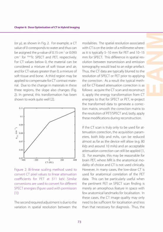
Chapter 6: Dose Optimisation of CT in Hybrid Imaging
EAN
M
73
(or µ), as shown in Fig . 2 . For example, a CT value of 0 corresponds to water and thus can be assigned the µ-value of 0 .15 cm-1 or 0 .093 cm-1 for 99mTc SPECT and PET, respectively . For CT values below 0, the material can be considered a mixture of soft tissue and air, and for CT values greater than 0, a mixture of soft tissue and bone . A third region may be applied to compensate for CT contrast mate-rial . Due to the change in materials in these three regions, the slope also changes (Fig . 2) . In general, this transformation has been shown to work quite well [2] .
Figure 2: Bi-linear scaling method used to convert CT pixel values to linear attenuation coefficients for PET at 511 keV . Similar conversions are used to convert for different SPECT energies (figure used with permission [1])
The second required adjustment is due to the variation in spatial resolution between the
modalities . The spatial resolution associated with CT is on the order of a millimetre where-as it is typically 5–10 mm for PET and 10–15 mm for SPECT . This difference in spatial res-olution between transmission and emission tomography would lead to an edge artefact . Thus, the CT data are typically blurred to the resolution of SPECT or PET prior to applying the correction . As a result the typical meth-od for CT-based attenuation correction is as follows: acquire the CT scan and reconstruct it, apply the energy transformation from CT energies to that for SPECT or PET, re-project the transformed data to generate a correc-tion matrix, smooth the correction matrix to the resolution of PET/SPECT and, lastly, apply these modifications during reconstruction .
If the CT scan is truly only to be used for at-tenuation correction, the acquisition param-eters, both kVp and mAs, can be reduced almost as far as the device will allow (e .g . 80 kVp and around 10 mAs) and an acceptable attenuation correction can still be applied [1, 3] . For example, this may be reasonable for brain PET, where MRI is the anatomical mo-dality of choice and CT is not used clinically . However, in many cases, the low-dose CT is used for anatomical correlation of the PET data . This can be particularly useful when the pertinent PET or SPECT scan finding is merely an amorphous feature in space with few anatomical landmarks for localisation . In these cases, the CT image quality may only need to be sufficient for localisation and less than that necessary for diagnosis . Thus, the
74
mAs can often be drastically reduced by a factor of possibly 3–5, depending on the task at hand and the size of the patient, leading to a considerable reduction in radiation dose to the patient compared to that for a diagnos-tic CT scan . The scan may also be easier to acquire, not requiring a breath hold or posi-tioning of the patient’s arms above the head for the entire scan .
Lastly, there may be instances where acquir-ing a diagnostic CT scan in conjunction with the PET scan makes the most sense . For ex-ample, it may be reasonable to acquire an abdominal/pelvic CT in conjunction with the PET scan, leading to a more efficient imaging approach as well as being more convenient for the patient . This approach may be partic-ularly helpful in children or other challenging patients, when the ability to perform both scans simultaneously may reduce the need for sedation or other approaches to immo-bilisation . On the other hand, diagnostic CT requires the highest radiation dose to be delivered to the patient . One should keep in mind that diagnostic CT is often applied to specific regions of the body such as the head/neck, the chest, the abdomen or the pelvis whereas the typical 18F-fluorodeoxy-glucose PET field of view encompasses all of these . Therefore, approaches that limit the diagnostic quality CT to the area of interest (e .g . to the abdomen and pelvis in the above example) while delivering a low dose to the rest of the field of view may be most appro-priate .
CT acquisition and dosimetryCT measures the differential absorption of X-rays passing through the patient and thus provides a 3D map of tissue density . The CT signal is more specifically related to electron density, which in many cases is well correlat-ed with mass density . X-rays are generated when electrons from the cathode of the x-ray tube are liberated via thermionic emission and accelerated towards the anode through an applied voltage . When the electrons strike the anode, they de-accelerate, leading to the production of bremsstrahlung and character-istic X-rays . The number of electrons striking the anode per second is characterised by the tube current in milliamperes (mA) . Thus the total number of electrons striking the anode is directly related to the product of the tube current and the duration of the exposure (in seconds) reported in mAs . Therefore, the total number of X-rays generated and subsequent-ly the X-ray dose to the patient is directly pro-portional to mAs . The voltage across the tube, reported as the kilovoltage peak (kVp), deter-mines the energy of the electrons striking the anode (in keV) by definition and thereby the maximum energy of the resultant X-rays . In addition, higher energy electrons are more ef-ficient at generating X-rays and higher energy X-rays are more likely to exit the tube and its filtration prior to reaching the patient . As a re-sult, the X-ray exposure or air kerma rate varies roughly as the square of the kVp .
The emitted X-rays, after passing through the patient, are detected by a two-dimensional
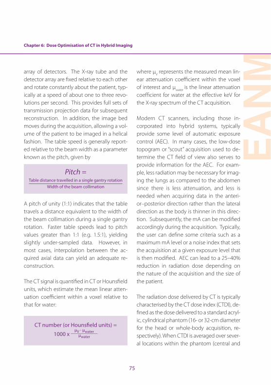
Chapter 6: Dose Optimisation of CT in Hybrid Imaging
EAN
M
75
array of detectors . The X-ray tube and the detector array are fixed relative to each other and rotate constantly about the patient, typ-ically at a speed of about one to three revo-lutions per second . This provides full sets of transmission projection data for subsequent reconstruction . In addition, the image bed moves during the acquisition, allowing a vol-ume of the patient to be imaged in a helical fashion . The table speed is generally report-ed relative to the beam width as a parameter known as the pitch, given by
Pitch = Table distance travelled in a single gantry rotation
Width of the beam collimation
A pitch of unity (1:1) indicates that the table travels a distance equivalent to the width of the beam collimation during a single gantry rotation . Faster table speeds lead to pitch values greater than 1:1 (e .g . 1 .5:1), yielding slightly under-sampled data . However, in most cases, interpolation between the ac-quired axial data can yield an adequate re-construction .
The CT signal is quantified in CT or Hounsfield units, which estimate the mean linear atten-uation coefficient within a voxel relative to that for water:
CT number (or Hounsfield units) =
1000 x μV - μwater
μwater
where μV represents the measured mean lin-ear attenuation coefficient within the voxel of interest and μwater is the linear attenuation coefficient for water at the effective keV for the X-ray spectrum of the CT acquisition .
Modern CT scanners, including those in-corporated into hybrid systems, typically provide some level of automatic exposure control (AEC) . In many cases, the low-dose topogram or “scout” acquisition used to de-termine the CT field of view also serves to provide information for the AEC . For exam-ple, less radiation may be necessary for imag-ing the lungs as compared to the abdomen since there is less attenuation, and less is needed when acquiring data in the anteri-or–posterior direction rather than the lateral direction as the body is thinner in this direc-tion . Subsequently, the mA can be modified accordingly during the acquisition . Typically, the user can define some criteria such as a maximum mA level or a noise index that sets the acquisition at a given exposure level that is then modified . AEC can lead to a 25–40% reduction in radiation dose depending on the nature of the acquisition and the size of the patient .
The radiation dose delivered by CT is typically characterised by the CT dose index (CTDI), de-fined as the dose delivered to a standard acryl-ic, cylindrical phantom (16- or 32-cm diameter for the head or whole-body acquisition, re-spectively) . When CTDI is averaged over sever-al locations within the phantom (central and
76
peripheral) and normalised by the pitch, it is referred to as CTDIvol . The dose–length prod-uct (DLP in units of mGy-cm) is the product of CTDIvol and the axial length of the CT acqui-sition in cm . DLP may be more closely linked to radiation risk as it also takes into account the extent of the scan . CTDIvol and DLP are routinely displayed on the CT operator’s con-sole during an acquisition and recorded in the structured dose report or in the DICOM head-er . It should be noted that these dose indices do not represent the radiation dose to a par-ticular patient, but that measured in standard phantoms . If the size of the patient is known, the CTDIvol can be modified and reported as the size-specific dose estimate (SSDE) [4] . Therefore, CT acquisition parameters should be reduced for smaller patients .
In order to investigate the range of expo-sures associated with the CT component of PET/CT, data for whole-body PET/CT from the American College of Radiology CT dose index registry were reviewed for over 28,000 PET/CT acquisitions from 35 facilities in the United States . The median values (and in-ter-quartile scores) for the CTDIvol and DLP re-ported for these scans were 6 .3 (4 .0, 9 .0) mGy and 541 (364, 831) mGy-cm, respectively . From these values, the estimates of the medi-an (and inter-quartile scores) of the effective dose are 8 .9 (6 .0, 13 .4) mSv [5] .
Best practice in patient positioning in CT acquisition for hybrid imagingPositioning of the patient during CT scan-
ning is important as it will affect the image quality as well as the dose of radiation that is delivered to the patient . The patient should be positioned so that the radiation from the X-ray beam is not applied to sensitive areas that do not need to be imaged . Using laser lights for positioning is helpful to ensure that the patient is in the isocentre of the gantry . If the patient is not in the isocentre then the dose delivered from the CT could be too low or too high . If the dose is too low, the image quality suffers and the scan may need to be repeated; too high and the patient receives unnecessary radiation dose . This, along with the use of a scout or topogram scan, can help in ensuring that the field of view is consistent with the exam that was ordered . For exam-ple, if a chest CT is ordered, the scout scan will show whether the entire chest cavity is in the field of view .
If motion is detected in a scan, it may need to be repeated; therefore it is essential that the patient is instructed to remain as still as possible during scanning and is positioned comfortably . If needed, soft positioning de-vices can be used to help the patient to hold still . In some paediatric patients or patients who are experiencing high amounts of anx-iety, a sedative can be administered to help with compliance during the scan .
Guidelines and national regulations for acquiring CT within hybrid imagingCT scans are routinely performed in the Unit-ed States and account for a large proportion
Chapter 6: Dose Optimisation of CT in Hybrid Imaging
EAN
M
77
of diagnostic radiology exams . The clinical in-formation that is gained from CT exams is in-credibly beneficial to patient outcomes and outweighs the risk that comes with the radi-ation exposure . However, in 2009 and 2010 reports were released regarding 400 patients who received radiation overdoses from a CT exam [6] . Similar reports regarding the risk of radiation have led to a growing concern regarding the safety of CT .
In the United States, the American College of Radiology (ACR) has published a practice pa-rameter for performing diagnostic CT scans [7] . This is not a set of rules but rather an educa-tional tool designed to advise on how to pro-vide care for patients undergoing CT scans . The audience for the ACR document is physicians . For technologists, the American Society of Radiologic Technologists (ASRT) has also pub-lished Computed Tomography Practice Stan-dards in their Practice Standards for Medical Imaging and Radiation Therapy [8] . Again, this is not a rule book, but a guide to appropriate practice in the performance of diagnostic CT .
National and local authorities may regulate what training and credentialling is required to perform CT in the context of hybrid im-aging . This varies greatly depending on the jurisdiction and may depend on whether the CT portion of the study is being used for di-agnostic purposes .
The field of radiology and CT continues to grow and evolve, with ongoing changes in
technology . Accordingly, all professionals working in the field need to ensure that they are fully acquainted with the latest develop-ments . Technologists need to be aware of published practice standards and the chang-es in regulations in order to perform scans that provide the best image quality and en-sure optimal patient care .
ConclusionThe addition of CT to both PET and SPECT has had a substantial impact on clinical prac-tice . However, CT exposes the patient to ion-ising radiation in addition to that associated with the administration of the radiopharma-ceutical . Therefore, basic knowledge of the physical aspects of CT and the factors that affect dose is essential for the nuclear med-icine professional involved in hybrid imaging . Care must also be taken to optimise the dose associated with CT . For example, the CT ac-quisition parameters should be adjusted de-pending on how the CT is to be used (i .e . for attenuation correction, anatomical correla-tion or diagnosis) and the size of the patient . Since PET/CT scans typically extend over a substantial portion of the patient’s body, it may be prudent to restrict the diagnostic study, when necessary, to the body region of clinical concern .
78
Chapter 6: Dose Optimisation of CT in Hybrid Imaging
References
1 . Fahey FH, Palmer MR, Strauss KJ, Zimmerman RE, Badawi RD, Treves ST . Dosimetry and adequacy of CT-based attenuation correction for pediatric PET: phantom study 1 . Radiology 2007;243:96–104 .
2 . Lonn A . Evaluation of method to minimize the effect of x-ray contrast in PET-CT attenuation correction . IEEE Medical Imaging Conference 2003;M6:146 .
3 . Rui X, Cheng L, Long Y, Fu L, Alessio AM, Asma E, et al . Ultra-low dose CT attenuation correction for PET/CT: analysis of sparse view data acquisition and recon-struction algorithms . Phys Med Biol 2015;60:7437–7460 .
4 . Boone J, Strauss K, Cody D, McCollough CH, McNitt-Gray MF, Toth TL . AAPM report No . 204: size-specific dose estimates (SSDE) in pediatric and adult body CT examinations . College Park, MD: American Association of Physicists in Medicine, 2013 .
5 . Alessio A, Sengupta D, Bhargavan-Chatfield M, Butler P, Kanal K, Fahey F . Survey of CT radiation dose levels during PET/CT from ACR CT Dose Index Registry . J Nucl Med 2015;56(Suppl 3):1696 .
6 . Harvey HB, Pandharipande PV . The federal government’s oversight of CT safety: regulatory possibilities . Radiology 2012;262:391–8 .
7 . ACR Practice Parameter for Performing and Interpret-ing Diagnostic Computed tomography (CT) . Reston, VA: 2014 .
8 . The Practice Standards for Medical Imaging and Radi-ation Therapy: Computed Tomography Practice Stan-dards . Albuquerque, NM: American Society of Radio-logic Technologists, 2015 .
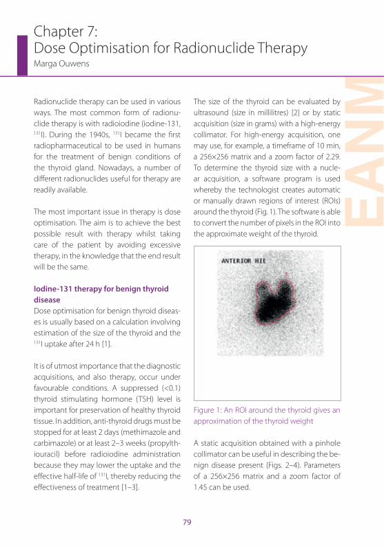
EAN
M
79
Chapter 7: Dose Optimisation for Radionuclide TherapyMarga Ouwens
Radionuclide therapy can be used in various ways . The most common form of radionu-clide therapy is with radioiodine (iodine-131, 131I) . During the 1940s, 131I became the first radiopharmaceutical to be used in humans for the treatment of benign conditions of the thyroid gland . Nowadays, a number of different radionuclides useful for therapy are readily available .
The most important issue in therapy is dose optimisation . The aim is to achieve the best possible result with therapy whilst taking care of the patient by avoiding excessive therapy, in the knowledge that the end result will be the same .
Iodine-131 therapy for benign thyroid diseaseDose optimisation for benign thyroid diseas-es is usually based on a calculation involving estimation of the size of the thyroid and the 131I uptake after 24 h [1] .
It is of utmost importance that the diagnostic acquisitions, and also therapy, occur under favourable conditions . A suppressed (<0 .1) thyroid stimulating hormone (TSH) level is important for preservation of healthy thyroid tissue . In addition, anti-thyroid drugs must be stopped for at least 2 days (methimazole and carbimazole) or at least 2–3 weeks (propylth-iouracil) before radioiodine administration because they may lower the uptake and the effective half-life of 131I, thereby reducing the effectiveness of treatment [1–3] .
The size of the thyroid can be evaluated by ultrasound (size in millilitres) [2] or by static acquisition (size in grams) with a high-energy collimator . For high-energy acquisition, one may use, for example, a timeframe of 10 min, a 256×256 matrix and a zoom factor of 2 .29 . To determine the thyroid size with a nucle-ar acquisition, a software program is used whereby the technologist creates automatic or manually drawn regions of interest (ROIs) around the thyroid (Fig . 1) . The software is able to convert the number of pixels in the ROI into the approximate weight of the thyroid .
Figure 1: An ROI around the thyroid gives an approximation of the thyroid weight
A static acquisition obtained with a pinhole collimator can be useful in describing the be-nign disease present (Figs . 2–4) . Parameters of a 256×256 matrix and a zoom factor of 1 .45 can be used .
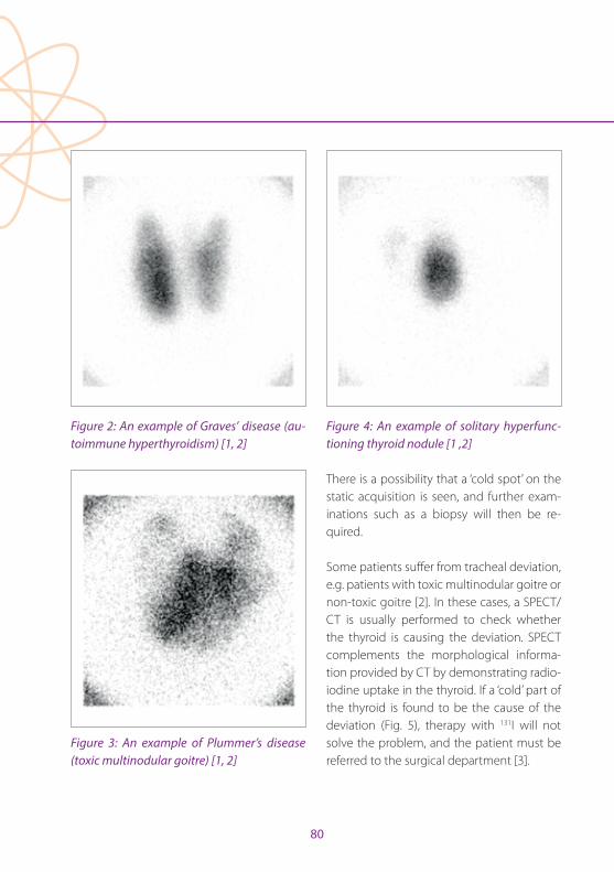
80
Figure 2: An example of Graves’ disease (au-toimmune hyperthyroidism) [1, 2]
Figure 3: An example of Plummer’s disease (toxic multinodular goitre) [1, 2]
Figure 4: An example of solitary hyperfunc-tioning thyroid nodule [1 ,2]
There is a possibility that a ‘cold spot’ on the static acquisition is seen, and further exam-inations such as a biopsy will then be re-quired .
Some patients suffer from tracheal deviation, e .g . patients with toxic multinodular goitre or non-toxic goitre [2] . In these cases, a SPECT/CT is usually performed to check whether the thyroid is causing the deviation . SPECT complements the morphological informa-tion provided by CT by demonstrating radio-iodine uptake in the thyroid . If a ‘cold’ part of the thyroid is found to be the cause of the deviation (Fig . 5), therapy with 131I will not solve the problem, and the patient must be referred to the surgical department [3] .
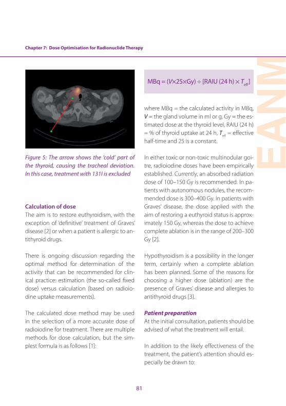
Chapter 7: Dose Optimisation for Radionuclide Therapy
EAN
M
81
Figure 5: The arrow shows the ‘cold’ part of the thyroid, causing the tracheal deviation. In this case, treatment with 131I is excluded
Calculation of doseThe aim is to restore euthyroidism, with the exception of ‘definitive’ treatment of Graves’ disease [2] or when a patient is allergic to an-tithyroid drugs .
There is ongoing discussion regarding the optimal method for determination of the activity that can be recommended for clin-ical practice: estimation (the so-called fixed dose) versus calculation (based on radioio-dine uptake measurements) .
The calculated dose method may be used in the selection of a more accurate dose of radioiodine for treatment . There are multiple methods for dose calculation, but the sim-plest formula is as follows [1]:
MBq = (V×25×Gy) ÷ [RAIU (24 h) × Teff]
where MBq = the calculated activity in MBq, V = the gland volume in ml or g, Gy = the es-timated dose at the thyroid level, RAIU (24 h) = % of thyroid uptake at 24 h, Teff = effective half-time and 25 is a constant .
In either toxic or non-toxic multinodular goi-tre, radioiodine doses have been empirically established . Currently, an absorbed radiation dose of 100–150 Gy is recommended . In pa-tients with autonomous nodules, the recom-mended dose is 300–400 Gy . In patients with Graves’ disease, the dose applied with the aim of restoring a euthyroid status is approx-imately 150 Gy, whereas the dose to achieve complete ablation is in the range of 200–300 Gy [2] .
Hypothyroidism is a possibility in the longer term, certainly when a complete ablation has been planned . Some of the reasons for choosing a higher dose (ablation) are the presence of Graves’ disease and allergies to antithyroid drugs [3] .
Patient preparation At the initial consultation, patients should be advised of what the treatment will entail .
In addition to the likely effectiveness of the treatment, the patient’s attention should es-pecially be drawn to:
82
• the slow onset of action of radioiodine
• the effect of radiation on the thyroid and the body
• the possibility of persistent or recurrent hyperthyroidism and what may be done about it
• the possibility of hypothyroidism and its symptoms, implications and treatment
• the need for regular follow-up to detect hypothyroidism [3] .
The nuclear medicine physician should in-form the patient of the common side effects of treatment:
• Nausea and vomiting are acute side effects . At lower doses there is a lower incidental risk .
• Patients with a large goitre may notice transient swelling of the goitre and dyspnoea . The swelling lasts for approximately 1 week following therapy and some discomfort or dyspnoea may be associated with it [1, 2] .
• Slight discomfort of the salivary glands may be present, but injury is uncommon [2] .
• Hypothyroidism is the main late side effect of radioiodine treatment . Its rate varies and its incidence continues to increase over time, so that life-long follow-up is essential [1, 2] .
• Administration of prednisone helps to prevent exacerbation of ophthalmopathy . The status of thyroid eye disease activity can be established by an experienced ophthalmologist [1–3] .
• A hypersensitivity reaction following the administration is very unlikely [2, 3] .
Absolute contra-indications [1–3] to therapy are pregnancy and breastfeeding:
• In female patients of childbearing potential, a routine pregnancy test should be performed within 72 h before the administration of 131I [1–3] .
• Breastfeeding should be stopped before administration of 131I .
Special recommendations and radiation pro-tection information, applicable with or with-out hospitalisation, must be orally discussed and, in addition, presented on paper [1, 2] prior to commencement of therapy:
• Depending upon national regulations, recommendations relating to conception may have to be provided . Generally, it is suggested that after 131I therapy, contraception should be used for 4–6 months by both men and women [1–3] .
• Breastfeeding may not be started after therapy .
• The patient should be encouraged to drink a large volume of fluid for a 24-h period following radioiodine therapy to lower the radiation dose to the bladder [2] .
• Contamination may occur at home . The most common cause of such contamination is radioactive urine . Sitting while urinating and washing of hands are important to prevent contamination .
Chapter 7: Dose Optimisation for Radionuclide Therapy
EAN
M
83
Another possibility is contamination with radioactive saliva . Tableware must not be shared before being cleaned (extra care must be taken when feeding children) and no kissing is permissible for a few days .
• The patient may need to take time off work/school for a period in accordance with the activity of radioiodine received and the nature of his or her work [2, 3] .
• The patient should avoid prolonged close contact with (small) children and pregnant women for a period in accordance with the activity of radioiodine received [2, 3] .
• Usually the patient is advised to keep a distance between themselves and (other) adults, and to keep contact times as short as possible for a limited amount of time, depending on the activity of radioiodine received . [2] .
• There may be restrictions on travel depending on the activity of radioiodine received [3] .
Iodine-131 therapy for thyroid carcinomaThere are multiple choices for establishing the necessary dose for radioiodine therapy, but administration of a ‘fixed dose’ of 131I is the simplest and most widely used method .
The indications for radioiodine are as follows:
• Remnant ablation: The dose may be 1 .11, 1 .85, 2 .59 or 3 .7 GBq, according to the volume of the tissue, the uptake and the level of thyroglobulin (Tg) [4, 5] (Fig . 6) .
• Lymph node metastases may be treated with 3 .7–6 .5 GBq . Cancers that extend through the thyroid capsule and have been incompletely resected are treated with 3 .7–7 .4 GBq [4, 5] .
• Patients with distant metastases are usually treated with 7 .4 GBq [4, 5]
The main goal is to ablate the thyroid tissue with one therapeutic dose . The thyroid tissue can be ablated successfully when it is small enough and there are no metastases . Metas-tases can also be treated, but with a palliative response . Therefore a patient with metasta-ses could return for further treatments [4] .
When the thyroid tissue is too large for abla-tion with only one therapeutic dose, or there are metastases in lymph nodes, an experi-enced surgeon is consulted to clarify wheth-er a second or third surgical intervention is possible before giving 131I therapy .
It is of utmost importance that the TSH val-ue exceeds 30 mIU/L [4] . This value may be obtained:
• At least 3–6 weeks after surgery in the absence of thyroid hormone replacement therapy [4, 5] .
• After 4–5 weeks of levothyroxine (LT4) withdrawal [4] or after 2–3 weeks of triiodothyronine withdrawal (LT3) [5] .
• After administration of recombinant TSH in two intramuscular injections on two consecutive days, if the patient is under hormonal treatment [4, 5] .
84
Patient preparation The nuclear medicine physician should in-form the patient of the most common side effects of treatment:
• An acute side effect is nausea and vomiting .
• Salivary dysfunction is the most common side effect associated with high-dose radioiodine . Prevention of salivary damage is an important issue .
• Salivation-inducing snacks, such as lemon candy, have proved helpful in preventing salivary side effects of 131I therapy . The sour ingredient stimulates the salivary glands to produce saliva, and the increase in salivary flow reduces radiation exposure . Lemon candy should not be used until at least 24 h following 131I therapy, because before that time it will just increase damage owing to a higher blood flow [4, 6] .
• Hypothyroidism will already be present owing to the thyroidectomy . The radioiodine therapy may exacerbate the hypothyroidism a little . Levothyroxine should be initiated a few days after radioiodine administration .
Absolute contra-indications [4] to therapy are pregnancy and breastfeeding .
• In female patients of childbearing potential, a routine pregnancy test should be performed within 72 h before each administration of 131I [4, 5] .
• Breastfeeding should be stopped 6–8 weeks before administration of 131I [4] .
Special recommendations and radiation pro-tection information must be orally discussed and, in addition, presented on paper prior to commencement of therapy [5]:
• Depending upon national regulations, recommendations relating to conception may have to be provided . Generally, it is suggested that after 131I therapy, contraception should be used for 4–6 months by both men and women [4] .
• Breastfeeding may not be started after therapy .
• Patients should be encouraged to drink a large volume of fluid for a 24-h period following radioiodine therapy to lower the radiation dose to the bladder [2] .
• Contamination may occur at home . The most common cause of such contamination is radioactive urine . Sitting while urinating and washing of hands are important to prevent contamination . Another possibility is contamination with radioactive saliva . Tableware must not be shared before being cleaned (extra care must be taken when feeding children) and no kissing is permissible for a few days .
• The patient may need to take time off work/school for a period of a duration in accordance with the activity of radioiodine received and the nature of his or her work [2, 3] .
• The patient should avoid prolonged close contact with (small) children and pregnant women for a period in accordance with the activity of radioiodine received [2, 3] .
Chapter 7: Dose Optimisation for Radionuclide Therapy
EAN
M
85
• Usually the patient is advised to keep a distance between themselves and (other) adults, and to keep contact times as short as possible for a limited amount of time, depending on the activity of radioiodine received [2] .
• There may be restrictions on travel in accordance with the activity of radioiodine received [3] .
Post-therapy whole-body scintigraphy is usually performed because of its high sen-sitivity in localising and characterising the extent of thyroid remnant and tumour and in detecting previously occult lesions . Scintig-raphy should not be performed sooner than 72 h or later than 7 days after radioiodine ad-ministration . Whenever available, SPECT or, preferably, SPECT/CT should be performed at the same time [4] . By providing a three-di-mensional image of involved lymph nodes, the SPECT study is an excellent way of vi-sualising lymph node lesions, whilst the CT component adds morphological information to the functional data furnished by SPECT alone [4, 5] .
Samarium-153 therapySamarium-153 (153Sm) EDTMP is a radiophar-maceutical that is effective in the treatment of painful metastatic disease of the skeletal system . The highest prevalence of such bone metastases occurs in prostate and breast carcinoma patients, in whom pain relief is the most important criterion for improve-ment in quality of life . Patients considered for
153Sm-EDTMP will have pain that limits nor-mal activities and/or is not easily controlled by regular analgesics . [7] .
Samarium-153 EDTMP concentrates in osteo-blastic lesions, with high tumour-to-normal bone tissue and tumour-to-soft tissue uptake ratios . While the benefits of 153Sm-EDTMP are evident after a single injection, treatment over a longer duration (weeks to months) is possible . The treatment can be repeated at an interval of at least 8 weeks, depending on the recovery of adequate bone marrow function .
The skeleton-seeking nature of this radio-pharmaceutical results in immediate delivery of beta radiation to disease localisations . Be-cause of the relatively long range of the beta particles emitted by 153Sm, the main dose-lim-iting factor in this treatment method is the toxicity to bone marrow cells . This toxicity restricts the maximum dose that can be used for the palliative treatment of painful skeletal metastases and precludes more extensive use of 153Sm-EDTMP in clinical settings .
Calculation of dosePatients are given a standard “fixed” dose: 37 MBq/kilogram body weight [7, 8] .
Patient preparationBefore the therapy is administered, some pre-cautions need to be taken . It must be ensured that kidney function is normal (owing to the excretion in urine) . Adequacy of bone mar-
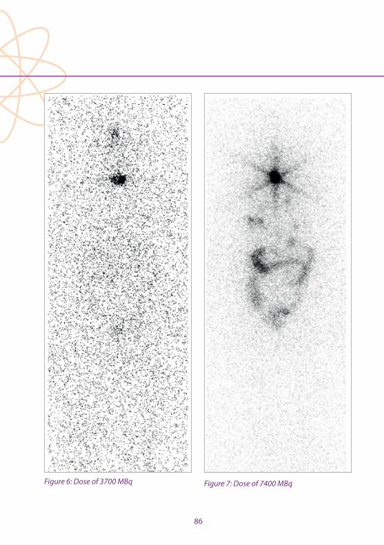
86
Figure 6: Dose of 3700 MBq Figure 7: Dose of 7400 MBq
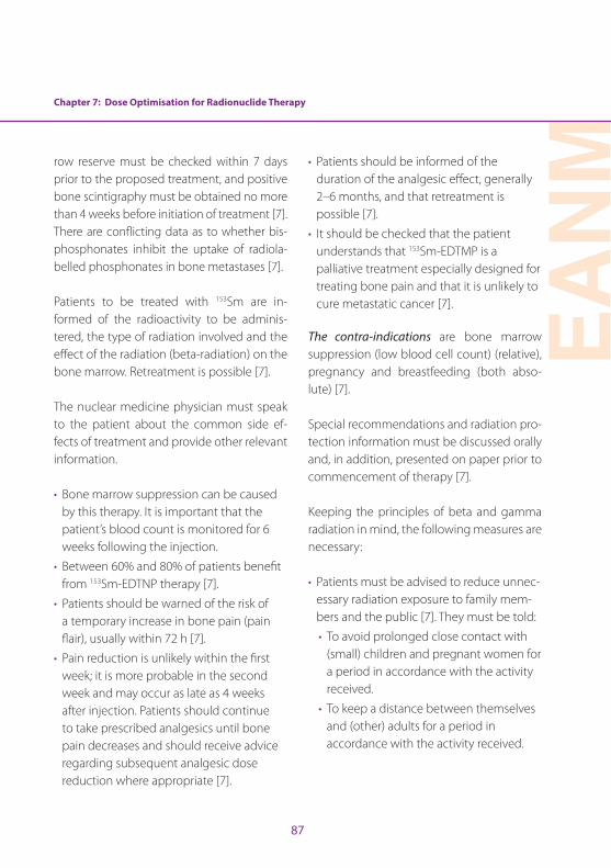
Chapter 7: Dose Optimisation for Radionuclide Therapy
EAN
M
87
row reserve must be checked within 7 days prior to the proposed treatment, and positive bone scintigraphy must be obtained no more than 4 weeks before initiation of treatment [7] . There are conflicting data as to whether bis-phosphonates inhibit the uptake of radiola-belled phosphonates in bone metastases [7] .
Patients to be treated with 153Sm are in-formed of the radioactivity to be adminis-tered, the type of radiation involved and the effect of the radiation (beta-radiation) on the bone marrow . Retreatment is possible [7] .
The nuclear medicine physician must speak to the patient about the common side ef-fects of treatment and provide other relevant information .
• Bone marrow suppression can be caused by this therapy . It is important that the patient’s blood count is monitored for 6 weeks following the injection .
• Between 60% and 80% of patients benefit from 153Sm-EDTNP therapy [7] .
• Patients should be warned of the risk of a temporary increase in bone pain (pain flair), usually within 72 h [7] .
• Pain reduction is unlikely within the first week; it is more probable in the second week and may occur as late as 4 weeks after injection . Patients should continue to take prescribed analgesics until bone pain decreases and should receive advice regarding subsequent analgesic dose reduction where appropriate [7] .
• Patients should be informed of the duration of the analgesic effect, generally 2–6 months, and that retreatment is possible [7] .
• It should be checked that the patient understands that 153Sm-EDTMP is a palliative treatment especially designed for treating bone pain and that it is unlikely to cure metastatic cancer [7] .
The contra-indications are bone marrow suppression (low blood cell count) (relative), pregnancy and breastfeeding (both abso-lute) [7] .
Special recommendations and radiation pro-tection information must be discussed orally and, in addition, presented on paper prior to commencement of therapy [7] .
Keeping the principles of beta and gamma radiation in mind, the following measures are necessary:
• Patients must be advised to reduce unnec-essary radiation exposure to family mem-bers and the public [7] . They must be told:
• To avoid prolonged close contact with (small) children and pregnant women for a period in accordance with the activity received .
• To keep a distance between themselves and (other) adults for a period in accordance with the activity received .
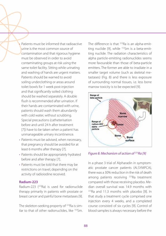
88
• Patients must be informed that radioactive urine is the most common source of contamination and that rigorous hygiene must be observed in order to avoid contaminating groups at risk using the same toilet facility . Sitting while urinating and washing of hands are urgent matters . Patients should be warned to avoid soiling underclothing or areas around toilet bowls for 1 week post-injection and that significantly soiled clothing should be washed separately . A double flush is recommended after urination . If their hands are contaminated with urine, patients should wash them abundantly with cold water, without scrubbing . Special precautions (catheterisation before and until 24 h after treatment [7]) have to be taken when a patient has unmanageable urinary incontinence .
• Patients must be advised, when necessary, that pregnancy should be avoided for at least 6 months after therapy [7] .
• Patients should be appropriately hydrated before and after therapy [7] .
• Patients must be told that there may be restrictions on travel, depending on the activity of radioiodine received .
Radium-223 Radium-223 (223Ra) is used for radionuclide therapy primarily in patients with prostate or breast cancer and painful bone metastases [9] .
The skeleton-seeking property of 223Ra is sim-ilar to that of other radionuclides, like 153Sm .
The difference is that 223Ra is an alpha-emit-ting nuclide [9], while 153Sm is a beta-emit-ting nuclide . The radiation characteristics of alpha particle-emitting radionuclides seems more favourable than those of beta-particle emitters . The former are able to irradiate in a smaller target volume (such as skeletal me-tastases) (Fig . 8) and there is less exposure of surrounding normal tissues, i .e . less bone marrow toxicity is to be expected [9] .
Figure 8: Mechanism of action of 223Ra [9]
In a phase 3 trial of Alpharadin in symptom-atic prostate cancer patients (ALSYMPCA), there was a 30% reduction in the risk of death among patients receiving 223Ra treatment compared with those receiving placebo . Me-dian overall survival was 14 .9 months with 223Ra and 11 .3 months with placebo [9] . In that study a treatment cycle comprised one injection every 4 weeks, and a completed course consisted of six cycles [9] . Control of blood samples is always necessary before the
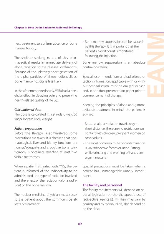
Chapter 7: Dose Optimisation for Radionuclide Therapy
EAN
M
89
next treatment to confirm absence of bone marrow toxicity .
The skeleton-seeking nature of this phar-maceutical results in immediate delivery of alpha radiation to the disease localisations . Because of the relatively short gestation of the alpha particles of these radionuclides, bone marrow toxicity is less likely .
In the aforementioned study, 223Ra had a ben-eficial effect in delaying pain and preserving health-related quality of life [9] .
Calculation of doseThe dose is calculated in a standard way: 50 kBq/kilogram body weight .
Patient preparationBefore the therapy is administered some precautions are taken . It is checked that hae-matological, liver and kidney functions are normal/adequate and a positive bone scin-tigraphy is obtained, revealing at least two visible metastases .
When a patient is treated with 223Ra, the pa-tient is informed of the radioactivity to be administered, the type of radiation involved and the effect of the radiation (alpha radia-tion) on the bone marrow .
The nuclear medicine physician must speak to the patient about the common side ef-fects of treatment:
• Bone marrow suppression can be caused by this therapy . It is important that the patient’s blood count is monitored following the injection .
Bone marrow suppression is an absolute contra-indication .
Special recommendations and radiation pro-tection information, applicable with or with-out hospitalisation, must be orally discussed and, in addition, presented on paper prior to commencement of therapy .
Keeping the principles of alpha and gamma radiation treatment in mind, the patient is advised:
• Because alpha radiation travels only a short distance, there are no restrictions on contact with children, pregnant women or other adults .
• The most common route of contamination is via radioactive faeces or urine . Sitting while urinating and washing of hands are urgent matters .
Special precautions must be taken when a patient has unmanageable urinary inconti-nence . The facility and personnelThe facility requirements will depend on na-tional legislation on the therapeutic use of radioactive agents [2, 7] . They may vary by country and by radionuclide, also depending on the dose .
90
When inpatient therapy is required, this should take place in an approved environ-ment with appropriately shielded rooms . The rooms must have separate washing and toi-let facilities and the patient must be under continuous surveillance by the staff [5, 7] .
The administration of 131I for the treatment of thyroid carcinoma is typically performed un-der hospitalisation (inpatient) and patients are discharged in accordance with national radioprotection regulations [5] .
The administration of all radionuclide thera-pies should be undertaken by appropriately trained medical staff with supporting nursing staff, when inpatient therapy is required, and an available medical physics expert . All of the clinical staff must know and respect the ra-diation protection measures relating to staff protection, handling of radiopharmaceuticals and patient safety . Lead shielding, lead dis-posal bins and lead transport holders are pro-vided to weaken the strength of the radiation . Staff must be aware of procedures for waste handling and disposal, handling of incidental contamination, and monitoring of personnel for accidental contamina-tion and control or limitation of its spread . Physicians responsible for treating patients should have a general knowledge of the pathophysiology and natural history of rele-vant diseases, should be familiar with alterna-tive forms of therapy and should be able to liaise closely with other physicians involved in patient management . Clinicians involved
in unsealed source therapy must also be knowledgeable about and comply with all applicable national and local legislation and regulations .
External and, more importantly, internal con-taminations need to be prevented; avoid-ance of internal contamination is especially important with 131I . Internal contamination, usually caused by accidental ingestion of a radionuclide, results in a higher dose to the personnel involved and is more difficult to eliminate than external contamination . The use of gloves when handling radioactivity is very important .
It is recommended to check personnel who have contact with patients treated with 131I (physicians, technologists, nursing staff ), for the possibility of internal contamination . The check can be performed periodically or at random . A check 24 hours after assisting therapy may result in a bigger chance of de-tection of an internal contamination . It is the responsibility of the health care professional to perform the appropriate checks, but na-tional regulations regularly demand checks twice a year, with supporting documenta-tion .
In many countries, therapies with 223Ra, 153Sm and low-dose radioiodine are performed in an outpatient setting .
In patients presenting with unmanageable urinary incontinence, inpatient treatment (if

Chapter 7: Dose Optimisation for Radionuclide Therapy
EAN
M
91
not regular standard of care) may be con-sidered, in accordance with the national legislations . This should be discussed before commencement of treatment . An indwelling catheter is recommended before therapy is given .
Radioiodine is preferentially administered orally (capsule), but can be administered in liquid form or intravenously in patients in whom vomiting is a problem . The liquid form has the advantages that it is less expensive and can be stored and easily dispensed as needed, but the risk of spoiling and contam-ination is higher [2] .
Samarium-153 and 223Ra are administered intravenously [7, 8] . Approval for the clini-cal use of radiopharmaceuticals may vary between countries . The choice of the ra-diopharmaceutical is based on the physical characteristics of the radionuclide in relation to the extent of metastatic disease, the bone marrow reserve and the availability of the ra-diopharmaceutical in individual countries [7] .
ConclusionIt is very important to administer the recom-mended dose for both diagnostic and ther-apeutic purposes . Thyroid disease is highly treatable with 131I, provided that precautions are maintained and radiation protection of the personnel involved is clearly under-stood . The patient needs to be informed of the need for prevention of contamination to other family members . The nuclear med-
icine technologist plays a major role in the diagnostic imaging and treatment of a pa-tient with thyroid disease; in particular, the technologist is responsible for performance of scintigraphy and dose calculations, there-by enabling the nuclear medicine physi-cian to make optimal treatment decisions . With 153Sm and 223Ra therapies, a “fixed dose” is used, and the patient also needs to be in-formed of the need for prevention of con-tamination . Certainly in the case of 223Ra therapy, the technologist plays an important role in patient care given that patients attend regularly for their treatment .
92
Chapter 7: Dose Optimisation for Radionuclide Therapy
References
1 . Piciu D . Section II . 2 . Radionuclide therapy in benign thyroid disease . In: Peștean C, Veloso Jéronimo V, Hogg P . Radionuclide metabolic therapy . Clinical aspects, do-simetry and imaging . A technologist’s guide . European Association of Nuclear Medicine; 2013:77–80 .
2 . Stokkel M, Handkiewicz Juank D, Lassmann M, Dietlein M, Luster M . EANM procedure guidelines for therapy of benign thyroid disease . Eur J Nucl Med Mol Imaging 2010;37:2218–2228 .
3 . Royal College of Physicians London . Radioiodine in the management of benign thyroid disease; clinical guide-lines . 2007 .
4 . Luster M, Clarke SE, Dietlein M, Lassman M, Lind P, Oyen WJG, et al . Guidelines for radioiodine therapy of differ-entiated thyroid cancer . Eur J Nucl Med Mol Imaging 2008;35:1941–1959 .
5 . Piciu D . Section II, 1 . Radionuclide therapy in thyroid carci-noma . In: Peștean C, Veloso Jéronimo V, Hogg P . Radionu-clide metabolic therapy . Clinical aspects, dosimetry and imaging . A technologist’s guide . European Association of Nuclear Medicine; 2013:61–76 .
6 . Nakada K, Ishibashi T, Takei T, Hirata K, Shinohara K, Katoh S, et al . Does lemon candy decrease salivary gland dam-age after radioiodine therapy for thyroid cancer . J Nucl Med 2005;46:261–266 .
7 . Bodei L, Lam M, Chiesa C, Flux G, Brans B, Chiti A . EANM procedure guideline for treatment of refractory metastat-ic bone pain . Eur J Nucl Med Mol Imaging 2008;35:1934–1940 .
8 . Mantel ES, Williams J . Section I, 1 . Principles in radionu-clide therapy . In: Peștean C, Veloso Jéronimo V, Hogg P . Radionuclide metabolic therapy . Clinical aspects, do-simetry and imaging . A technologist’s guide . European Association of Nuclear Medicine; 2013:9–17 .
9 . Shore ND . Radium-223 dichloride for metastatic castra-tion-resistant prostate cancer: The urologist’s perspective . Urology 2015;85:717–724 .
EAN
M
93
Chapter 8: Paediatric Dose OptimisationAna Isabel Santos and Diego De Palma
Paediatric population and the importance of dose optimisationThe paediatric population is a very inhomoge-neous patient group broadly encompassing those aged 0–18 years, the precise definition varying between countries in accordance with legal differences with respect to the up-per age limit . The distinction in medicine be-tween this group and adults is justified, given that the human body grows and matures up until roughly the age of 18 years . Growing or renewing tissues are more sensitive to the mutagenic effect of ionising radiation (which is why in adults the tissues more susceptible to radiation damage are the bone marrow and the gastrointestinal tract epithelium) . The younger the child, the larger the number of growing cells; this implies that children are much more sensitive to radiation damage than adolescents and that the latter are more sensitive than adults . Using the current system of risk assessment, the risk of developing a sol-id tumour after radiation exposure is about 3 times higher for a 1-year-old child and 1 .8 times higher for a 10-year-old child compared with an adult [1, 2] . Gender also influences the risk: compared with males, females are ex-posed to a further 50% increase in relative risk owing to the higher radiosensitivity of breast tissue and the associated incidence of breast cancer [ICRP 103] . An additional fact that con-tributes in explaining the higher radiosensitiv-ity of children is their longer life expectancy .
It is also to be borne in mind that a risk es-timate is a statistical entity derived from the
data available for much larger exposed pop-ulations such as the Japanese atomic bomb survivors [1, 3] or people living in Belarus and Ukraine at the time of the Chernobyl fallout [4] . Although, for example, no epide-miological study has to date found a defi-nite association between the diagnostic use of iodine-131 and increased risk of thyroid cancer [5, 6], the utmost attention and care are required in children when balancing the potential impact of exposure associated with a diagnostic procedure against the expected benefit .
Radiation burden and ways to minimise itIn nuclear medicine, the radiation burden associated with a procedure, measured as the effective dose (ED), is generally ex-pressed as mSv/MBq of administered ac-tivity of the radiopharmaceutical . The given value is modified according to the age of the child (for practical reasons, rounded at fixed reference ages), but the calculation admits as the only variable the amount of activity administered . All other factors in-fluencing the residence time of the radio-pharmaceutical in the body, e .g . frequency of voiding, bowel status, hydration, and renal function, are considered as constant or roughly divided into two categories (e .g . normal/abnormal renal function) . Radio-pharmaceuticals primarily undergo renal excretion; this means that the bladder is the critical organ for calculating the ED . Teach-ing a toilet-trained child to drink generously
94
Chapter 8: Paediatric Dose Optimisation
and to void the bladder at fixed intervals is a safe and simple way to reduce the radiation burden . Similarly, administration of small amounts of furosemide in a toddler helps, as does frequent changing of diapers .
With the increased use of hybrid cameras, concern over the additive radiation burden and risks of CT [7, 8] is increasing . When performing hybrid procedures involving CT, such as SPECT/CT and PET/CT, the im-portance of dose optimisation must not be neglected, and it has to be obtained mainly with the use of standardisation of low-dose protocols [2, 9, 10] .
The EANM dosage cardConsidering that in nuclear medicine, the ED received after the administration of a ra-diopharmaceutical depends on the admin-istered activity, there is a definite need to standardise and minimise the latter . The first version of the EANM dosage card was pre-pared and published in 1990 by members of the EANM Paediatric Committee [11] . At that time, the main purpose was to help in har-monising administered activities across Eu-rope; this card, substantially an “expert con-sensus paper”, used the child’s weight as the reference for scaling down activities . It has to be noted that the value was calculated us-ing body surface; the authors thereafter gave weight as the reference because it is easier to obtain and, in children, displays a direct relationship with body surface . A minimum was also set for each radiopharmaceutical,
in order to avoid an excessively long scan time . Another problem encountered at that time was the variability in adult reference activities, which was later partially overcome by the publication as law in many EC coun-tries of the Diagnostic Reference Levels . In 2005 an important paper [12] was published, aimed at defining a scaling system based on keeping the ED stable across the different ages . The authors found that radiopharma-ceuticals can be grouped into three classes, each with a different set of scaling factors . This led to the publication of a new version of the EANM dosage card [13], and for the first time an online dosage calculator was made available via the EANM website .
This version of the EANM dosage card re-ceived some criticism, mainly focussed on the “minimum activity to be administered” concept [14–17] . A footnote was then added admitting that experienced teams can use activities lower than those recommended, but asserting that the overall value of the card as a general reference remained intact [18] . After this publication, a joint EANM–SN-MMI group started a process aimed at har-monising recommendations between the two societies [19, 20] . The last update in this respect was published in 2014 [21, 22] and a further new version of the EANM paediatric dosage card is now available, both as an on-line calculator and as an App for Android/IOS devices [http://www .eanm .org/publications/dosage_calculator .php?navId=285] .
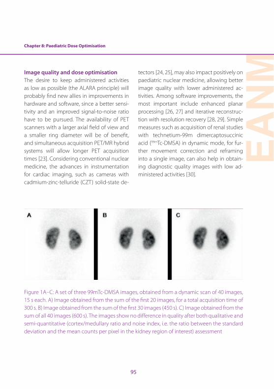
Chapter 8: Paediatric Dose Optimisation
EAN
M
95
Image quality and dose optimisationThe desire to keep administered activities as low as possible (the ALARA principle) will probably find new allies in improvements in hardware and software, since a better sensi-tivity and an improved signal-to-noise ratio have to be pursued . The availability of PET scanners with a larger axial field of view and a smaller ring diameter will be of benefit, and simultaneous acquisition PET/MR hybrid systems will allow longer PET acquisition times [23] . Considering conventional nuclear medicine, the advances in instrumentation for cardiac imaging, such as cameras with cadmium-zinc-telluride (CZT) solid-state de-
tectors [24, 25], may also impact positively on paediatric nuclear medicine, allowing better image quality with lower administered ac-tivities . Among software improvements, the most important include enhanced planar processing [26, 27] and iterative reconstruc-tion with resolution recovery [28, 29] . Simple measures such as acquisition of renal studies with technetium-99m dimercaptosuccinic acid (99mTc-DMSA) in dynamic mode, for fur-ther movement correction and reframing into a single image, can also help in obtain-ing diagnostic quality images with low ad-ministered activities [30] .
Figure 1A–C: A set of three 99mTc-DMSA images, obtained from a dynamic scan of 40 images, 15 s each . A) Image obtained from the sum of the first 20 images, for a total acquisition time of 300 s . B) Image obtained from the sum of the first 30 images (450 s) . C) Image obtained from the sum of all 40 images (600 s) . The images show no difference in quality after both qualitative and semi-quantitative (cortex/medullary ratio and noise index, i .e . the ratio between the standard deviation and the mean counts per pixel in the kidney region of interest) assessment

96
Best practice principlesWhile the need to estimate risk related to the radiation burden must always be kept in mind, this risk must not be allowed to over-shadow those risks associated with ionising radiation-free procedures when, like MRI, they require sedation, general anaesthesia or the use of contrast media .
Another clinical risk that must be weighed against the risk associated with radiation exposure is the danger of missing some clinically relevant information because of either (a) poor quality radionuclide imaging on account of a low count density or move-ment artefacts due to an excessively long ac-quisition time or (b) failure to perform what would have been a useful scan .
Take-home messagesThe process of dose optimisation and re-duction in paediatric nuclear medicine is a comprehensive one, with different and con-current approaches [10, 23] .
A practical approach to dose reduction en-tails:
• Compliance with the justification process: only studies capable of yielding results that may change the clinical management of the child should be performed, especially when dealing with benign diseases;
• Use of (basically) the activities calculated according the EANM paediatric dosage card;
• Use of rational systems to expedite elimination of the radiopharmaceutical via urine or stools;
• Careful evaluation of the impact of modern or new hardware/software technologies . For example, compared with PET/CT, PET/MRI requires a longer acquisition time per bed position, due to the MRI sequences . As PET image quality represents a product of acquisition time and radiotracer activity, the implication is that radiation exposure may be reduced by lowering the injected radiotracer activity .
Chapter 8: Paediatric Dose Optimisation
EAN
M
97
References
1 . Pierce DA, Shimizu Y, Preston DL, Vaeth M, Mabuchi K . Studies of the mortality of atomic bomb survi-vors . Report 12, Part I . Cancer: 1950-1990 . Radiat Res 1996;146:1–27 .
2 . Gelfand MJ . Dose reduction in pediatric hybrid and pla-nar imaging . Q J Nucl Med Mol Imaging 2010;54:379–388 .
3 . Ozasa K, Shimizu Y, Suyama A, Kasagi F, Soda M, Grant EJ, et al . Studies of the mortality of atomic bomb survivors, Report 14, 1950-2003: an overview of cancer and non-cancer diseases . Radiat Res 2012;177:229–243 .
4 . Fushiki S . Radiation hazards in children – lessons from Chernobyl, Three Mile Island and Fukushima . Brain Dev 2013;35:220–227 .
5 . Dickman PW, Holm L-E, Lundell G, Boice JD, Hall P . Thy-roid cancer risk after thyroid examination with 131I: a population-based cohort study in Sweden . Int J Cancer 2003;106:580–587 .
6 . Hahn K, Schnell-Inderst P, Grosche B, Holm LE . Thyroid cancer after diagnostic administration of iodine-131 in childhood . Radiat Res 2001;156:61–70 .
7 . Sodickson A . CT radiation risks coming into clearer fo-cus . BMJ 2013;346:f3102 .
8 . Mathews JD, Forsythe AV, Brady Z, Butler MW, Goergen SK, Byrnes GB, et al . Cancer risk in 680,000 people ex-posed to computed tomography scans in childhood or adolescence: data linkage study of 11 million Aus-tralians . BMJ 2013;346:f2360 .
9 . Treves ST, Falone AE, Fahey FH . Pediatric nuclear medi-cine and radiation dose . Semin Nucl Med 2014;44:202–209 .
10 . Fahey FH, Treves ST, Adelstein SJ . Minimizing and com-municating radiation risk in pediatric nuclear medicine . J Nucl Med 2011;52:1240–1251 .
11 . Piepsz A, Hahn K, Roca I, Ciofetta G, Toth G, Gordon I, et al . A radiopharmaceuticals schedule for imaging in paediatrics . Eur J Nucl Med 1990;17:1–3 .
12 . Jacobs F, Thierens H, Piepsz A, Bacher K, Wiele CV de, Ham H, et al . Optimised tracer-dependent dosage cards to obtain weight-independent effective doses . Eur J Nucl Med Mol Imaging 2005;32:581–588 .
13 . Lassmann M, Biassoni L, Monsieurs M, Franzius C, Jacobs F, for the EANM Dosimetry and Paediatrics Committees . The new EANM paediatric dosage card . Eur J Nucl Med Mol Imaging 2007;34:796–798 .
14 . Warbey VS, Schleyer PJ, Barrington SF, O’Doherty MJ . The new EANM paediatric dosage card — does it con-form to ALARA for PET/CT? Eur J Nucl Med Mol Imaging 2007;34:1881–1882 .
15 . Holm S, Borgwardt L, Loft A, Graff J, Law I, Højgaard L . Paediatric doses — a critical appraisal of the EANM paediatric dosage card . Eur J Nucl Med Mol Imaging 2007;34:1713–1718 .
16 . Lassmann M, Biassoni L, Monsieurs M, Franzius C, EANM Dosimetry and Paediatrics Committees . The new EANM paediatric dosage card: additional notes with respect to F-18 . Eur J Nucl Med Mol Imaging 2008;35:1666–1668 .
17 . Lassmann M, Biassoni L, Monsieurs M, Franzius C . The new EANM paediatric dosage card: additional notes with respect to F-18 . Eur J Nucl Med Mol Imaging 2008;35:2141 .
18 . Lassmann M, Biassoni L, Monsieurs M, Franzius C, Jacobs F . The new EANM paediatric dosage card . Eur J Nucl Med Mol Imaging 2009;36:1–2 .
19 . Gelfand MJ, Parisi MT, Treves ST, Pediatric Nuclear Med-icine Dose Reduction Workgroup . Pediatric radiophar-maceutical administered doses: 2010 North American consensus guidelines . J Nucl Med 2011;52:318–322 .
20 . Treves ST, Parisi MT, Gelfand MJ . Pediatric radio-pharmaceutical doses: new guidelines . Radiology 2011;261:347–349 .
21 . Treves ST, Lassmann M, for the EANM/SNMMI Pediatric Dosage Harmonization Working Group . International Guidelines for Pediatric Radiopharmaceutical Admin-istered Activities . J Nucl Med 2014;55:869–870 .
98
22 . Lassmann M, Treves ST, EANM/SNMMI Paediatric Dosage Harmonization Working Group . Paediatric radiophar-maceutical administration: harmonization of the 2007 EANM paediatric dosage card (version 1 .5 .2008) and the 2010 North American consensus guidelines . Eur J Nucl Med Mol Imaging 2014;41:1036–1041 .
23 . Fahey FH, Treves ST, Lassmann M . Dose optimization in pediatric nuclear medicine . Clin Transl Imaging [Online] 2016 . Available from: doi:10 .1007/s40336-015-0153-8
24 . Imbert L, Poussier S, Franken PR, Songy B, Verger A, Mo-rel O, et al . Compared performance of high-sensitivity cameras dedicated to myocardial perfusion SPECT: a comprehensive analysis of phantom and human im-ages . J Nucl Med 2012;53: 1897–1903 .
25 . Gunalp B . Role of cardiac ultrafast cameras with CZT solid-state detectors and software developments on radiation absorbed dose reduction to the patients . Ra-diat Prot Dosimetry 2015;165:461–463 .
26 . Hsiao EM, Cao X, Zurakowski D, Zukotynski KA, Drubach LA, Grant FD, et al . Reduction in radiation dose in mer-captoacetyltriglycerine renography with enhanced planar processing . Radiology 2011;261:907–915 .
27 . Fahey FH, Zukotynski K, Zurakowski D, Markelewicz R, Falone A, Vitello M, et al . Beyond current guidelines: reduction in minimum administered radiopharmaceu-tical activity with preserved diagnostic image quality in pediatric hepatobiliary scintigraphy . Eur J Nucl Med Mol Imaging 2014;41:2346–2353 .
28 . Sheehy N, Tetrault TA, Zurakowski D, Vija AH, Fahey FH, Treves ST . Pediatric 99mTc-DMSA SPECT performed by using iterative reconstruction with isotropic resolution recovery: improved image quality and reduced radio-pharmaceutical activity . Radiology 2009;251:511–516 .
29 . Stansfield EC, Sheehy N, Zurakowski D, Vija AH, Fahey FH, Treves ST . Pediatric 99mTc-MDP bone SPECT with ordered subset expectation maximization iterative reconstruction with isotropic 3D resolution recovery . Radiology 2010;257:793–801 .
30 . Piepsz A, Colarinha P, Gordon I, Hahn K, Olivier P, Roca I, et al . Guidelines on 99mTc-DMSA scintigraphy in children . [Online] EANM . pp . 1–7 . Available from: http://www .eanm .org/publications/guidelines/gl_paed_dmsa_scin .pdf [Accessed: 31 January 2016]
EAN
M
99
Chapter 9: Occupational Radiation ProtectionSebastijan Rep
IntroductionThe main task of radiation protection is to en-sure that the received radiation exposure is restricted to a minimum, thereby protecting everybody in the department . An important aspect of this process is knowledge and under-standing of radiation sources and of the meth-ods that can be used to limit exposure to these sources . This knowledge can be deployed to minimise external exposure as well as to pre-vent internal and external contamination .
The three basic methods used to reduce the external radiation hazard are (a) restriction of the time of exposure, (b) maximisation of the distance from the source and (c) shielding [1–4] . Good radiation protection practices require optimisation of these fundamental techniques .
Internal radiation exposure occurs when the body is contaminated internally with a radio-nuclide . Thus, internal radiation protection is concerned with preventing or minimising the deposition of radioactive substances in personnel .
Another important aspect in the radiation protection process is knowledge of the type of radiation emitted from the isotopes (sources), which is required for selection of the best available protection method [1, 2] .
Protection of workers against external radiation exposure TimeThe less time one spends standing in the field
of radiation, the lower is the dose received . Working at high speed, proper preparation and practice outside the range of radiation ensure that the actual exposure time is in-deed the minimum time needed to perform the tasks while simultaneously restricting the likelihood of error that would necessitate repeated performance of the same tasks . Examples of good practice that shorten the exposure time are:
• Precise planning and organisation of work
• Work rate
• Restrictions to ensure that personnel remain within the radiation field only for the actual duration of work
• Distribution of work among more staff
• Preparation of equipment in a clean environment
There is a direct linear relationship between radiation dose and time (dose = dose rate × time) . The radiation dose increases in linear fashion as the duration of exposure increases [5] .
DistanceRadiation dose rate decreases with increasing distance from the source . The decrease in the dose rate with distance is not linear: dose rate from a point radiation source decreases by the square of the distance . A radiation source can be regarded as a point source when one is within three times the largest dimension of the source . For this reason, almost all sources in nuclear medicine can be assumed to be
100
point sources . It is also important to note that for point sources in air the radiation spreads uniformly to all sides [6] .
When extrapolating from measurements at longer distances, assuming a point-source distribution can lead to significant overesti-mation of dose rates closer to the patient . A linear-source model with attenuation correc-tion can be used to more accurately reflect the activity distribution for some procedures . In a line-source model, the fall-off of the dose with distance depends on both the distance and the length of the source [1, 7] . In prac-tice, this implies that doubling the distance in any direction will reduce to one-quarter the value of the exposure .
Bearing in mind the above, maximisation of distance from the radiation source is a sim-ple and very effective method for reducing radiation exposure to workers . The distance between workers and the radioactive source can be maximised by using long-handled tools to keep radioactive materials well away from the body and by storing radioactive materials as far from workers as possible [8] .
The distance from the source of radiation is increased if:
• Pliers, tweezers and other adapted tools are used .
• Remotely operated tools are used .
• Television surveillance is used .
• One communicates at distance .
It is important to know how to derive the dose rate at a certain distance from a known dose rate at a different distance . In this case, a slightly modified equation is used for the dependence of dose rate on distance [1–4]:
I₁ * D₂₁ = I₂ * D₂₂
where I1 is the intensity at the original dis-tance (D1) and I2 is the intensity at a new dis-tance (D2) [5] .
ShieldingAlthough maximisation of distance from the source and limitation of the time of expo-sure are important measures for protection against external radiation, the shielding fac-tor is also very important for reduction of the dose rate in a nuclear medicine depart-ment . In practice the shielding depends on the type of work, the type of radiation, the total activity and the practice and workload of each area in the department . In fact, all departments are designed and built to in-corporate barriers that take these factors into account .
All sources used in nuclear medicine arrive in their own container (shield) and best practice warrants that all prepared activities and sources are manipulated or transported within this container, with additional protec-tion . The shielding normally varies between 3 and 6 mm of lead equivalent, according to the energy and type of radiation . However,
Chapter 9: Occupational Radiation Protection
EAN
M
101
protection can in fact be provided by any material with a sufficient thickness .
Due to the scattering of gamma rays and the bremsstrahlung, the radiation shield is diffi-cult to calculate . For this reason, it is advis-able to consult a radiation protection officer [1–4] . The method of shielding depends on the type of radiation . Gamma radiation de-creases exponentially with the thickness of the shield and can be written as:
D = Dx * 1
2n
where n is the number of half-value layers (HVL): n = d/d1/2 . DX indicates the dose rate without a shield and D, the dose rate with a shield (at the same distance from the source) [5] .
Values of HVL for photons with different en-ergies (keV) are shown in Table 1 .
The same equation can be written using the tenth-value layer (TVL):
D = Dx * 1
10n
where n is the number of tenth-value layers: n = d/d1/10 [5] .
These formulas include only photons that pass through the shield and do not entail any interaction . It turns out that the contribution
of stray radiation from the thick shielding is substantially higher than the attenuated ra-diation that comes directly from the source . Therefore, the equations shown are only es-timates [10] .
A 0 .25-mm lead apron will provide a dose re-duction of 59% for 99mTcO4 (140 keV) while a 0 .5-mm lead apron, weighing about 8 .5 kg, will provide a dose reduction of about 76% [11, 12] . A lead apron is of little use at higher energies, examples being 131I (360 keV) and 18F (511 keV) . Thus a 0 .25-mm lead apron will provide a calculated dose reduction of about 3% for 18F and 6% for 131I while a 0 .5-mm lead apron will provide a calculated dose reduc-tion of about 6% for 18F and 11% for 131I [13] .
Beta radiation contributes to external ex-posure in two ways: via the beta rays them-selves, i .e . fast electrons (or positrons), and via scattered radiation (bremsstrahlung) that is the result of interaction of the electrons or positrons with matter . Beta particles are relatively easy to stop, and therefore brems-strahlung is the major contributor to external exposure . The proportion of bremsstrahlung radiation can be reduced by using a material with a low atomic number Z (polyethylene, acrylic glass) instead of a high Z material . Therefore, the internal shield is intended only to stop beta particles and is enclosed by an outer sheath made of material with a high Z (lead), which reduces the bremsstrahlung [1, 14] .

102
Specific gamma-ray dose constant (Γ)For every isotope it is possible to use the specific gamma-ray dose constant (Γ) to esti-mate an absorbed dose . The constants of the isotopes more commonly used in nuclear medicine are published in the literature . The absorbed dose is directly proportional to the time of exposure and the activity at the point of origin and inversely proportional to the square of the distance from the same point . It can be seen from Table 2 that for 1 MBq of 18F at 1 m and for an exposure of 1 h, an ab-sorbed dose of 0 .143 mSv is obtained .
Protection of workers against internal radiation exposure Internal contamination is the presence of radioactive material inside the human body and results from the ingestion or inhalation of radioactive material (radionuclides) . The more common ways for radionuclides to en-ter the body are:
• With food and drink (ingestion)
• By breathing (inhalation)
• Through the skin (absorption)
• Through open wounds (absorption)
The received dose can depend on the mode of entry into the body . In contrast to exter-nal exposure, alpha and beta emitters are the most dangerous sources of internal exposure [1, 10] .
The concentration of radionuclides in the body decreases over time, in the absence
of new entry, because of natural radioactive decay and because of biological elimination from the body via the digestive tract, urinary tract and exhalation . Options for artificially accelerated washout of radionuclides in the body are very limited, so the main protective measure against internal exposure is preven-tion of entry of these materials into the body . Accordingly, protection begins with the prevention of contamination of the environ-ment in which people live and work .
Unlike in external exposure, in an internal ex-posure the doses received cannot be directly measured, but only calculated or estimated [15] .
Protection against internal exposure is based on the following principles:
• Limitation of open sources: radiation sources and processes that can cause radioactive contamination of surface or air should be limited to a reasonably small number of specific areas .
• Monitoring of areas with radiation sources: Premises on which there is radiation activity should be appropriately designed architecturally . Surfaces should be made of materials that allow efficient decontamination, and special care must be taken to ensure controlled drainage and good ventilation with air filtration . Work with open sources involving a possibility of contamination is carried
Chapter 9: Occupational Radiation Protection
EAN
M
103
out within a controlled area to which access is physically restricted . Only workers who meet certain conditions (regarding personal protective equipment, training, etc .) are allowed to work in this area, and at the exit there must be suitable equipment for measurement of personal contamination and, if needed, decontamination .
• Protection of workers: Eating, drinking and smoking must be strictly forbidden in areas where open sources are present .
• Protection of workers: Workers must always wear personal protective equipment when manipulating sources . This is intended to prevent contamination of the skin (through the wearing of protective clothing) and to limit the intake of radioactive substances by inhalation (through use of respiratory equipment) [10, 15] .
Effective half-lifeDifferent tissues and organs in the human body display differing susceptibility to a va-riety of radioactive isotopes . It is known that iodine accumulates in the thyroid, calcium in the bones, etc . Some other elements are evenly distributed throughout the body .
Also, radioactive isotopes of each element accumulate in specific target organs after entering the body . Thus, 90Sr and 223Ra ac-cumulate in the bones and 131I in the thy-roid while 60Co and 137Cs are distributed
throughout the body . No substance, radioac-tive or not, remains in the body indefinitely . Normal biological processes remove all sub-stances from the organism; their concentra-tion decreases approximately exponentially . On the basis of the biological and radioactive half-time, the effective half-time can be cal-culated . The equation for calculating the ef-fective half-life is:
TEF = TF * TB
TF + TB
where TEF is the effective half-life; TF is the half-time of the isotope and TB is the biologi-cal half-life [1, 5] .
Personnel monitoring for external and internal radiation exposure The best way to estimate the total dose to which a person has been exposed is by means of personal dosimetry . In the case of nuclear medicine both whole-body dosim-etry and extremity dosimetry are advised . External radiation exposure is measured by personnel monitoring devices .
Three main types of monitoring device are in use today: film badges, thermoluminescent dosimeters (TLD) and optically stimulated luminescent (OSL) dosimeters . If the body is exposed more or less equally, the dosimeter should be worn on the trunk of the body . This will allow the dose to internal organs to be estimated .
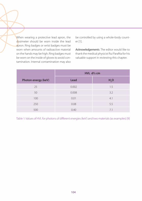
104
When wearing a protective lead apron, the dosimeter should be worn inside the lead apron . Ring badges or wrist badges must be worn when amounts of radioactive material on the hands may be high . Ring badges must be worn on the inside of gloves to avoid con-tamination . Internal contamination may also
be controlled by using a whole-body count-er [1] .
Acknowledgements . The editor would like to thank the medical physicist Rui Parafita for his valuable support in reviewing this chapter .
HVL d½ cm
Photon energy (keV) Lead H2O
25 0 .002 1 .5
50 0 .008 3 .2
100 0 .01 4 .1
250 0 .08 5 .5
500 0 .40 7 .1
Table 1: Values of HVL for photons of different energies (keV) and two materials (as examples) [9]
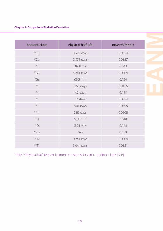
Chapter 9: Occupational Radiation Protection
EAN
M
105
Radionuclide Physical half-life mSv m2/MBq h
64Cu 0 .529 days 0 .0324
67Cu 2 .578 days 0 .0157
18F 109 .8 min 0 .143
67Ga 3 .261 days 0 .0204
68Ga 68 .3 min 0 .134
123I 0 .55 days 0 .0435
124I 4 .2 days 0 .185
125I 14 days 0 .0384
131I 8 .04 days 0 .0595
111In 2 .83 days 0 .0868
13N 9 .96 min 0 .148
15O 2 .04 min 0 .148
82Rb 76 s 0 .159
99mTc 0 .251 days 0 .0204
201Tl 3 .044 days 0 .0121
Table 2: Physical half-lives and gamma constants for various radionuclides [5, 6]
106
References
1 . Mattsson S, Hoeschen C, eds . Radiation protection in nuclear medicine . Berlin Heidelberg New York: Springer; 2013:109–128 .
2 . Le Heron J, Padovani R, Smith I, Czarwinski R . Radiation protection of medical staff . Eur J Radiol 2010;76:20–23 .
3 . Woodings S . Radiation protection recommendation for I-131 thyrotoxicis, thyroid cancer and phaeo-chromocytoma patients . Australas Phys Eng Sci Med 2004;27:118–128 .
4 . Markelewicz RJ Jr, Lorenzen WA, Shusterman S, Grant FD, Fahey FH, Treves ST . Radiation exposure to family care-givers and nurses of pediatric neuroblastoma patients receiving 131I-metaiodobenzylguanidine (131I-MIBG) therapy . Clin Nucl Med 2013;38:604–607 .
5 . Wells P, ed . Practical mathematics in nuclear medicine technology . Society of Nuclear Medicine; 1999:93–113 .
6 . Syeda NA . Physics and engineering of radiation detec-tion . Amsterdam: Elsevier; 2007:65–7 .
7 . Siegel JA, Marcus CS, Sparks RB . Calculating the ab-sorbed dose from radioactive patients: the line-source versus point-source model . J Nucl Med 2002;43:1241–1244 .
8 . Radiation Safety Manual Radioisotopes . Available at: http://www2 .bakersfieldcollege .edu/erp/Radiation/chp6 .htm (5 .6 .2016) .
9 . Markovic S, Spajic R . Radiacija i zdravje . Drustvo za bio-medicinsko inzenirstvo i medicinsko fiziko . Beograd 2001 .
10 . Khalil MM, ed . Basic sciences of nuclear medicine . Berlin Heidelberg New York: Springer; 2011:15–17 .
11 . Warren-Forward H, Cardew P, Clack L, McWhirter K, Johnson S, Wessel K . A comparison of dose savings of lead and lightweight aprons for shielding of 99m-tech-netium radiation . Radiat Prot Dosim 2007;124:89–96 .
12 . Ahmed S, Zimmer A, McDonald N, Spies S . The effec-tiveness of lead aprons in reducing radiation exposures from specific radionuclides . J Nucl Med 2007;48:470 .
13 . Saha GB . Physics and radiobiology of nuclear med-icine . 3rd ed . Berlin Heidelberg New York: Springer; 2006:56–70 .
14 . Office of Federal and State Materials and Environmen-tal Management Programs, US Nuclear Regulatory Commission . Consolidated guidance about materials licenses: program-specific guidance about medical use licenses . NUREG-1556 . 2008; vol 9, Rev . 2
15 . Turpin BK, Morris VR, Lemen L, Weiss BD, Gelfand MJ . Minimizing nuclear medicine technologist radiation ex-posure during 131I-MIBG therapy . Health Phys 2013;104 (2 Suppl 1):S43–S46 .
EAN
M
107
IntroductionDesigning a new department is time con-suming and complex; however, getting the design and layout correct will create an en-vironment that is safe and efficient for both staff and patients . Outlining the operations of the department and the types of service offered is the first step in developing a design plan, which can be modified throughout the project . The design process must ensure engagement with all the relevant stake-holders, both internal and external . External stakeholders, including referrers, should be consulted to better define the types of ser-vice to be offered (nuclear medicine and/or PET); this will enable you to estimate the expected number of patients and bookings, remembering to allow for future growth and development . Engaging the staff in review-ing the current workflows and protocols will assist with compliance if changes in process are required . Compliance with regulations is mandatory, with advice needed from the medical physicist and radiation safety expert on minimum room size, shielding and other services, with a particular focus on radiation shielding and occupancy rates . This chapter summarises the issues that need to be ad-dressed when designing a new department, provides a step-by-step guide to department design and outlines the role of the technolo-gist in the design process .
Requirements of a nuclear medicine departmentThe requirements of a new department will
depend on the functionality and services be-ing offered . The design and floorplan will vary significantly according to whether the de-partment will have a single gamma camera, a SPECT/CT, a PET/CT or a PET/MRI, whether it will have cardiac exercise stress testing fa-cilities and whether it will offer radionuclide therapy . Therefore one of the first steps in the process is to engage your invested stake-holders, including the institution (hospital) executive, referrers, other departments and clinical areas within the hospital and the pa-tients who will use the service . This process offers an ideal opportunity to review your current practice (if updating an existing de-partment) or to define the goals of the new department, which should help to identify the services to be provided and therefore the equipment needs . For example, if you are setting up a small single gamma camera practice in a small rural (non-metropolitan) hospital adjacent to a small radiology depart-ment, then it is likely that you will be required to provide routine non-urgent studies and an occasional urgent acute procedure and to operate Monday to Friday business hours (8 a .m . to 5 p .m .) . Therefore, a single SPECT/CT, a small hot lab, one office, a small reception with a waiting room to house up to five or six people, a shared reporting area with ra-diology and other standard features would be considered adequate . However, a large university hospital providing acute services, surgical and interventional procedures, can-cer care services, extensive outpatient clinics covering all specialties and a 24-hour emer-
Chapter 10: Nuclear Medicine Department DesignElizabeth Bailey
108
Chapter 10: Nuclear Medicine Department Design
gency department will likely have three or more SPECT/CT systems, at least one or two PET/CT scanners, cardiac stress testing facil-ities, lead-lined inpatient rooms for radionu-clide therapies and all the standard features needed to provide a comprehensive service . Knowing this information prior to designing the layout and workflow of the department will ensure that the new nuclear medicine department will meet the expectations and needs of patients and referrers .
Regulations and minimum standards at a lo-cal, state and national level can vary between countries . During the design process, consid-eration must also be given to international standards regulating radiation protection, shielding and waste storage, hot laborato-ry minimum specifications, gamma camera/SPECT/PET room layout and size and man-datory facility services based on department size and occupancy rate [1–5] . It is important to consult infection control and occupational safety guidelines as these will provide informa-tion on the number and location of patient/staff toilets and hand-wash basins, dirty utility rooms, waiting rooms, medical services includ-ing oxygen, suction, nurse call buttons, cardiac arrest/emergency alarm and closed circuit tele-vision (CCTV) monitoring . These must be taken into consideration when defining the layout and will impact on the space available for hot laboratories, uptake rooms for PET, changing rooms, cardiac stress testing facilities and con-sultation rooms, possibly affecting the number of services that can be performed .
Issues to consider when designing a nuclear medicine departmentWhen designing a nuclear medicine depart-ment, there are several factors and issues that should be considered . The project plan and development working group should include representation from each of the profession-al groups within the department, including nuclear medicine physicians, radiologists, nuclear medicine technologists, medical physicists, radiopharmacists and nursing and administrative staff . This will ensure that the department meets the needs of the patients, referrers and other important stakeholders while creating an efficient and safe work en-vironment for the employees .
Be aware of the other departments and clin-ical areas surrounding the new floorplan, especially paediatrics, ultrasound waiting rooms and maternity clinics, as this will im-pact on shielding requirements . Areas to be considered include not only those that are immediately adjacent to the department but also those above and below it . All attempts should be made to ensure that hot areas are not adjacent to high-risk areas; for example, the PET hot lab should not share a common wall with the maternity clinic .
It is common practice in most nuclear med-icine departments to install lead-lined glass in gamma camera control rooms so as to be able to observe the patient during the nu-clear medicine test . This is still recommend-ed for the nuclear medicine gamma camera
Chapter 10: Nuclear Medicine Department Design
EAN
M
109
area; however, CCTV monitoring is preferred for the PET unit as the thickness of lead glass needed to provide adequate shielding has a high refractory index, making it very diffi-cult to clearly and safely observe the patient . It is also very costly to install . Consideration should also be given to the use of CCTV monitoring in the hot patient waiting ar-eas, uptake rooms and radionuclide thera-py rooms throughout the nuclear medicine department . This will reduce staff radiation dose and allow the nursing and technologist staff to safely monitor the patients in a ‘cold’ non-radiation area .
In PET departments, the thickness of lead required to provide adequate shielding for staff can make doors very heavy and can represent a manual handling risk for staff . Therefore the designs should be reviewed in consultation with a medical physicist expert in order to ensure compliance with radia-tion safety regulations while minimising the occupational manual handling risks . A maze design may be an option that minimises the number of heavy doors required yet still pro-vides adequate radiation shielding .
The design should include clearly defined ‘hot’ and ‘cold’ areas throughout the department plan with restricted access to patients . The nuclear medicine department staff should have areas within the department such as the control room, staff recreation room and toilet that are non-radiation areas . These should be clearly identified in the design and workflow .
Consideration should also be given to the location of radiation-sensitive equipment such as gamma counters, dose calibrators and area monitors . If the background radi-ation level is too high, the measurements will be erroneous and therefore impact on clinical results . If this is unavoidable, then the rooms containing this type of equip-ment will need to be appropriately shielded . Given the higher risk of surface contami-nation and radiation spills in areas such as the hot laboratories, radiopharmacies and gamma and PET camera rooms, it is pref-erable that the flooring is continuous with no joins, non-absorbent and easy to clean . The bench surfaces ideally should be stain-less steel with a lip at the front to prevent spillage from bench to floor and continuous to the back surface or wall . The IAEA provide guidelines on radiation safety standards that incorporate radiopharmacy and hot labora-tory design [6] .
The relevant clinical staff, including the tech-nologist, will need to develop a concise list of the types of study and the radionuclides to be used in the department . If the de-partment is to offer a full suite of diagnostic procedures, PET tracers (with short and long half-lives), radioiodine therapies and other radionuclide therapies, then this will signifi-cantly affect the equipment needs, shielding, waste storage in the hot laboratories and quality control minimum standards . These must be defined before designing the layout and workflow of the new department .
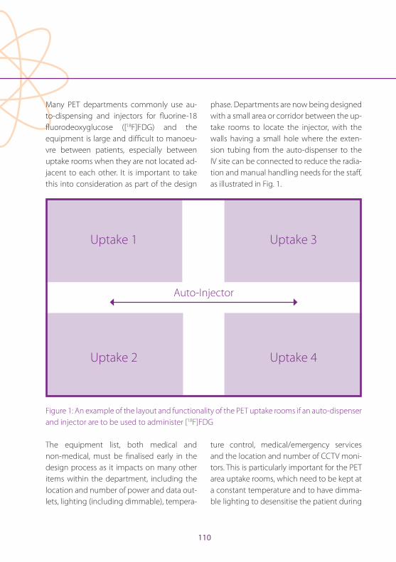
110
Many PET departments commonly use au-to-dispensing and injectors for fl uorine-18 fl uorodeoxyglucose ([18F]FDG) and the equipment is large and diffi cult to manoeu-vre between patients, especially between uptake rooms when they are not located ad-jacent to each other . It is important to take this into consideration as part of the design
phase . Departments are now being designed with a small area or corridor between the up-take rooms to locate the injector, with the walls having a small hole where the exten-sion tubing from the auto-dispenser to the IV site can be connected to reduce the radia-tion and manual handling needs for the staff , as illustrated in Fig . 1 .
Uptake 1
Uptake 2
Uptake 3
Uptake 4
Auto-Injector
Figure 1: An example of the layout and functionality of the PET uptake rooms if an auto-dispenser and injector are to be used to administer [18F]FDG
The equipment list, both medical and non-medical, must be fi nalised early in the design process as it impacts on many other items within the department, including the location and number of power and data out-lets, lighting (including dimmable), tempera-
ture control, medical/emergency services and the location and number of CCTV moni-tors . This is particularly important for the PET area uptake rooms, which need to be kept at a constant temperature and to have dimma-ble lighting to desensitise the patient during

Chapter 10: Nuclear Medicine Department Design
EAN
M
111
the uptake period . The ambient temperature in the gamma camera rooms will be critical to avoid damage to the sensitive NaI detec-tor crystals, especially if equipment is to be installed and not used for a significant time prior to department operation .
As part of the planning and development process, new workflows for patients and staff must be identified, especially with respect to the transit of patients into and out of the de-partment . It is preferable to avoid transiting through or past ‘cold’ staff areas when enter-ing and exiting the department, specifically the control rooms, reporting rooms and staff recreation rooms .
Layout and design considerationsDefining the types of study to be performed in the new department will determine the equipment needs and therefore the design and layout of the facility . There are, however, many common features that will be manda-tory in order to comply with local and nation-al regulations irrespective of the equipment to be installed . These include emergency services, radiation shielding, room sizes, in-fection control for location and number of hand-washing facilities, size of reception areas and office space and the minimum standards for patient holding bays . Organ-isations such as the American Association of Physicists in Medicine (AAPM), the Inter-national Council on Radiological Protection (ICRP) and the International Atomic Energy Agency (IAEA) provide guidelines on radia-
tion shielding calculations, room layout and method for determining occupancy rates [1, 4, 7] . Local and national health regulators often provide health facility guidelines that cover minimum room sizes, infection control standards, safe workplace recommendations and non-medical equipment needs [7, 8] .
The design plan and layout will vary depend-ing on whether you are renovating or build-ing within an existing floorspace as com-pared to being given a ‘blank canvas’ with the ability to design the space as required, which is often easier . Current design guidelines and regulations specific to the country and the area that you are building must be tak-en into consideration, as must the radiation safety regulations . There are many examples of effective department designs, especially for new PET departments, that have been successfully implemented [9] . The design lay-out examples given below list the potential medical and non-medical equipment nec-essary for a nuclear medicine department ranging in size from a small single gamma camera department to a larger department with multiple gamma cameras and PET/CT .
Example 1 – a single gamma camera, either SPECT or SPECT/CT (Fig. 2)• Waiting room to house up to six patients;
• Reception and administrative staff area with enough space for a single receptionist and an office for a practice manager;
• SPECT or SPECT/CT camera room with the radiation shielding determined as per the
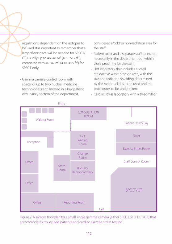
112
regulations, dependent on the isotopes to be used . It is important to remember that a larger fl oorspace will be needed for SPECT/CT, usually up to 46–48 m2 (495–517 ft2), compared with 40–42 m2 (430–455 ft2) for SPECT only;
• Gamma camera control room with space for up to two nuclear medicine technologists and located in a low patient occupancy section of the department,
considered a ‘cold’ or non-radiation area for the staff ;
• Patient toilet and a separate staff toilet, not necessarily in the department but within close proximity for the staff ;
• Hot laboratory that includes a small radioactive waste storage area, with the size and radiation shielding determined by the radionuclides to be used and the procedures to be undertaken;
• Cardiac stress laboratory with a treadmill or
Waiting Room
Reception
Offi ce
Offi ce
Offi ce Reporting Room
SPECT/CT
Staff Control Room
Exercise Stress Room
Toilet
Patient Trolley Bay
CONSULTATION ROOM
Hot Waiting Room
Change Room
Hot Lab/Radiopharmacy
Store Room
Entry
Exit
Figure 2: A sample fl oorplan for a small single gamma camera (either SPECT or SPECT/CT) that accommodates trolley bed patients and cardiac exercise stress testing
Chapter 10: Nuclear Medicine Department Design
EAN
M
113
bicycle to be used for myocardial perfusion studies . The room will need to be fitted with a full emergency services panel and cardiac arrest response trolley with a defibrillator . A separate changing room may be needed, depending on the number of studies to be performed per day;
• Consultation/injection room equipped with the materials needed for injection of the radiopharmaceuticals;
• Reporting room with one reporting workstation;
• A small storage room for general stock items and non-medical stores;
• A small staff room with a beverage bay and sitting area that is located in a ‘cold’ or non-radiation area of the department .
Example 2 – two gamma cameras, with 1 × SPECT and 1 × SPECT/CT (Fig. 3)• Waiting room to house up to ten patients;
• Reception and administrative staff area with enough space for two receptionist staff and an office for an office/data manager;
• SPECT camera room with the radiation shielding determined as per the regulations dependent on the isotopes to be used, size 40–42 m2 (430–455 ft2);
• SPECT/CT camera room with the radiation shielding determined as per the regulations dependent on the isotopes to be used . It is important to remember that a larger floorspace will be needed for SPECT/CT, usually up to 46–48 m2 (495–517 ft2);
• Gamma camera control room with space for up to three nuclear medicine technologists and located in a low patient occupancy section of the department, considered a ‘cold’ or non-radiation area for the staff;
• Patient toilet and a separate staff toilet;
• Hot laboratory and/or radiopharmacy for manufacture that includes a radioactive waste storage area . The size and equipment needs of the hot laboratory and waste storage will vary depending on the radionuclides used and the diagnostic or therapeutic services performed;
• Cardiac stress laboratory with a treadmill or bicycle to be used for myocardial perfusion studies . The room will need to be fitted with a full emergency services panel and cardiac arrest response trolley with a defibrillator;
• A pass-through hatch may be useful in certain areas within the department, for example between the hot laboratory and the cardiac exercise laboratory or the radionuclide therapy room . This will avoid staff transporting patient doses in heavy shielded canisters between rooms;
• A separate change room for the cardiac patients located either adjacent to or opposite the cardiac exercise stress room;
• A consultation or interview room with a patient trolley bed that can be used for brain perfusion and activation studies;
• An injection room equipped with the materials needed for administration of the radiopharmaceuticals to patients;
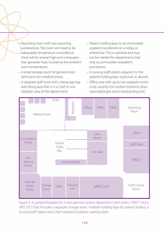
114
• Reporting room with two reporting workstations . The room will need to be adequately temperature controlled as there will be several high-end computers that generate heat, increasing the ambient room temperature;
• A small storage room for general stock items and non-medical stores;
• A separate staff room with a beverage bay and sitting area that is in a ‘cold’ or non-radiation area of the department;
• Patient holding bays to accommodate a patient transferred on a trolley or wheelchair . This is optional and may not be needed for departments that only accommodate outpatient procedures;
• A nursing staff station adjacent to the patient holding bays (optional, as above);
• Offi ce area with up to two separate rooms to be used by the nuclear medicine physi-cian/radiologist and a medical physicist,
Entry
Waiting Room
Consultation Room
Hot Waiting Room
Exercise Stress Room
Change Room
Toilet Treatment oom SPECT/CT
SPECT
Staff Toilet
Staff Control Room
Offi ce
Offi ceOffi ceOffi ce Reporting RoomRe
cept
ion
Hot Lab/
StoreRoom
Nurses Station
Patient Trolley
Bay
Figure 3: A sample fl oorplan for a two-gamma camera department with both a SPECT and a SPECT/CT that includes a separate change room, multiple holding bays for patient trolleys, a nursing staff station and a ‘hot’ radioactive patient waiting room

Chapter 10: Nuclear Medicine Department Design
EAN
M
115
radiopharmacist or chief nuclear medicine technologist;
• A separate shielded waiting room to be used by patients following administration of the radiopharmaceutical, especially for tests that require patients to wait between imaging time points or to be monitored, e .g . cardiac patients . It is important to remember that there is a requirement that all attempts be made to keep the exposure to members of the general public, especially pregnant women and small children, as low as reasonably achievable (ALARA) [10, 11] .
Example 3 – 1 × SPECT, 1 × SPECT/CT and 1 × PET/CT (Fig. 4)• The nuclear medicine department should
include the areas outlined in example 2; however, the waiting area will need space for up to 12 patients . The items listed below are specific to the PET/CT area .
• PET/CT camera room with a minimum size of 48–50 m2 (516–538 ft2) and the option to include radiation therapy lasers and treatment planning imaging palettes (‘flatbed’ palettes);
• A PET/CT equipment room that is temperature controlled, either in the camera room itself or located in a separate area in close proximity to the machine;
• A PET control room for up to three nuclear medicine technologists and a nurse;
• A separate PET patient toilet, which should be able to accommodate a patient in a wheelchair;
• A PET hot laboratory, which may include a small waste storage area if the facility will be using longer half-life tracers such as iodine-124 or copper-64;
• A consultation or interview room to be used for non-radioactive patients prior to injection;
• A common report room for both nuclear medicine and PET is preferable, with at least two reporting workstations, and it may be desirable to have a concertina door to separate the two reporting zones if needed;
• A separate change room located in the PET area close to the department exit so that patients can easily find the exit when finished, thereby minimising the PET staff radiation dose;
• Uptake rooms, with the number needed dependent on the type of PET system installed, the number and type of studies to be performed per day and the space available;
• If the facility will be performing studies on patients who require a higher level of care during the uptake period or plans to do complex procedures such as brain activation studies, catheterisation or anaesthetics, a larger uptake room (12–13 m2 or 125-139 ft2) will be required, fitted with full medical services including anaesthetics;
• A separate radiopharmacy specifically for manufacture, dispensing and tracer development . If a hot cell is required, remember to check the floor weighting and access to compressed air and

116
nitrogen . A hot cell can weigh up to 8 tonnes and require a large amount of space;
• A meeting room or combined meeting room/library is a good addition to larger departments to allow for internal as well as external meetings and to provide continuing education opportunities for the staff .
When defi ning the layout, functionality and workfl ow of the department, it is important to include clearly designated ‘cold’ or non-ra-diation areas for the staff at a reasonable dis-tance from any radioactive sources, includ-ing the patients, X-ray sources such as CT and the hot laboratories . A separate ‘hot’ waiting area located within the department with ap-propriate shielding is suggested to minimise
Figure 4: A sample fl oorplan for a larger department that includes two gamma cameras, both a SPECT and SPECT/CT, and a PET/CT . The addition of a meeting room/library can be used for continuing education of the staff and allows additional space for both internal and external clinical and non-clinical meetings
Offi ce
Offi ce Meeting Room
Offi ce
Cons
ulta
tion
Room
Repo
rtin
gRo
om
Chan
ge
Room
Upt
ake
1
Upt
ake
2
Toile
t
Upt
ake
3
Upt
ake
4
PET/CT
SPECT
SPECT/CTToilet
Consultation Room
StoreRoom N
urse
s Sta
tion
StoreRoom
ChangeRoom
ExerciseStressRoom
Hot Lab
Patient Trolley
Bay
SPECT Control Room
PET Control Room
Waiting Room
Reception
Ope
n O
ffi ce
Ar
ea
Staff Entry
PatientEntry
Entry/Exit
Chapter 10: Nuclear Medicine Department Design
EAN
M
117
the radiation exposure to reception and ad-ministrative staff as well as members of the general public . The use of mobile lead shields may be helpful, especially in the radionu-clide therapy areas, where nursing and other non-medical imaging staff may be monitor-ing the patient for medical complications .
Radionuclide therapy facilitiesThe equipment, floorspace, shielding, room layout and waste storage requirements will vary depending on the radionuclide thera-pies being provided and the radiation pro-tection legislation specific to each country . The radiation exposure rate for a patient at the time of discharge following radionuclide therapy and the waste storage and disposal guidelines, e .g . with regard to the need for sewerage holding tanks, vary significantly between countries [3, 4, 11] . The mandatory shielding based on the radionuclides to be used, the minimum room size and the sewer-age and waste requirements must be incor-porated during the design phase .
Newer radionuclide therapies using lute-tium-177 are commonly performed as a day procedure in most countries due to the low gamma emission (<15%) and the me-dium-energy beta emission . It is common practice to treat four to six patients in a single room, with each patient being administered 7–8 GBq and the treatment taking 4–6 h to perform . As part of the design process, con-sideration must be given to the total activity in the room at a given time as well as the oc-
cupancy rate of the room for staff, patients and visitors . The radiation shielding require-ments with respect to infrastructure such as walls, flooring and ceiling, internal protection devices including mobile or fixed personal protective equipment, the minimum room size to safely accommodate six patients and the need for a separate toilet impact significantly on the room layout; it must be ensured that a ‘cold’ zone is provided for the staff involved in administering the therapy and monitoring the patient [12] .
The use of radioactive iodine, specifically io-dine-131, for treatment of thyroid cancer or for labelling of mIBG or Lipiodol in the treat-ment of metastatic phaeochromocytoma, neuroblastoma or liver cancer, will require a fully equipped isolation room or ward . The room size, radiation shielding, waste storage facilities (including holding tanks for biolog-ical radioactive waste) and discharge expo-sure rates should be determined on the basis of the radiation regulations and guidelines for the individual country . Patients treated with iodine-131 must be admitted and iso-lated from the general public for a period of time that will vary between countries . The determination of the isolation period is based on a number of factors including the administered activity, the allowable exposure rate at the time of discharge and personal factors specific to the patient including living arrangements, cognitive ability and indepen-dence status as measured using, for example, ECOG performance status scoring [13] .
118
Radiation safety and regulatory considerationsThe radionuclides to be used in the depart-ment and the number of X-ray imaging equipment items, such as CT, to be installed will impact dramatically on the level of shielding required . The AAPM, ICRP and IAEA provide detailed guidelines on shielding re-quirements that are recognised internation-ally [10, 14] . These guidelines should be used under the guidance of a medical physics expert and consideration must be given to the routine doses administered for each pro-cedure and the number of studies to be per-formed per day as these factors will impact on the amount of any particular radioisotope that will be stored and used in the hot lab, and the radiation level of the unsealed (‘hot’ patient) sources moving throughout the de-partment .
The IAEA and local authorities from many oth-er countries provide comprehensive state-based, national and international guidelines on radiation protection and waste storage . Area monitoring of the background radia-tion and contamination in staff areas may be a regulatory requirement . This may include the checking and recording of contamina-tion on the skin or clothing for staff working in the hot laboratories, mandating the need for wall or bench mounted surveillance me-ters at the exit of the laboratory . Waste stor-age needs will be determined by the tracers and isotopes used, if they are gamma, beta or alpha emitters, the energy and half-life of
the products manufactured and the activi-ties . This is less of an issue in PET due to the short half-life of most PET tracers; however, if iodine-124 or copper-64 are to be used, then a heavily shielded long-life waste storage should be located near the PET laboratory [15] . These guidelines often include informa-tion on security of sources and each country will have specific regulations with which you will need to comply . It is therefore important to identify during the design phase a secure delivery access point for the daily radiophar-maceutical deliveries that uses a path with a low general public occupancy rate .
Nuclear medicine department design: A step-by-step guideThe process for designing a new department or remodelling an existing layout will vary between departments and even countries due to differences in the role of the various stakeholders and staff members and the mandated regulations . This is a step-by-step guide to designing a nuclear medicine de-partment from the perspective of a nuclear medicine technologist that can be used as a guide .
I . Identify the size, shape and location of the proposed floorspace .
II . List the equipment needs and the types of equipment that will be installed in the new department .
III . Review the guidelines and regulations specifically relating to minimum room size, room fit-out specifications such
Chapter 10: Nuclear Medicine Department Design
EAN
M
119
as medical services, power, and air conditioning as well as the fire safety and radiation safety regulations for shielding and occupancy . This should be done in consultation with a medical physicist or a radiation safety expert .
IV . Determine the department workflow for patients, staff and visitors . This will assist in defining the restricted and limited access areas, the ‘hot and ‘cold’ areas within the department and the location of staff amenities such as staff recreation room, lockers and toilet .
V . Draft a layout for the department to include all equipment and services .
VI . In consultation with the other relevant stakeholders, create a room data sheet for each area or room within the department that concisely defines the room specifications, both medical and non-medical .
VII . Review the room data sheets with a focus on lighting, temperature control (especially in the PET area), medical service needs for each space, power (including high voltage for rooms in which CT equipment is to be installed) and the type of flooring and bench surfaces in the radiation area, including camera rooms and hot laboratories . Review the number and location of data outlets for computing equipment and the location of CCTV monitors .
VIII . Modify the draft plan after reviewing the room data sheets and confirm
that the layout will meet the needs of the department and other invested stakeholders such as patients and referrers .
Technologist’s role in the design processThe technologist is an integral part of the de-sign team and is the best person to advise on workflows, clinical procedures and patient needs . There are certainly particular tasks for which the technologist should have owner-ship and these have been identified as:
a . Determine the patient, staff and general public workflow . This will include identifying how patients will move through the department when undergoing procedures . This may differ between outpatients and inpatients, between walking patients and patients who are in a wheelchair or bed bound, and between PET and other nuclear medicine procedures .
b . Provide details on the number of staff employed and their role within the department . This will help to identify staff who will require a separate office and to assess the need for any shared office space, separate physics laboratories, radiopharmacy facilities for manufacture and dispensing and meeting rooms or library facilities for ongoing education and professional development . It can also identify training needs and discrepancies in the skills of the existing staff .
120
c . Review the current types and number of studies performed daily, weekly and monthly and evaluate whether this will change in the new or updated facility . This information will be used to determine the equipment needs and the expected occupancy rates of the rooms and to identify any future staff education or training needs . The medical physics expert can then use this information to determine the shielding requirements for each space .
d . Accurately determine future storage needs . Storage of both clinical and non-clinical equipment can often be problematic in new facilities, so this assessment is important . It is common for a new department to increase its workload in the first 12 months of operation so the design must take into consideration future development and growth to include room for expansion .
e . Carefully review the room data sheets, which will list all services, equipment, furnishings and flooring for each area . Specifically look at:
ix . Lighting
x . Air conditioning or temperature control, especially in a PET facility
xi . Data and power outlets
xii . The height and depth of the benches, desks and workstations
xiii . The location of any CCTV monitoring to comply with the safety regulations for patient monitoring during a procedure
xiv . The optimal location of handwashing facilities to comply with infection control legislation
xv . What you will need in each of the rooms if you will be doing paediatric studies: perhaps a TV and/or DVD player in the camera room, a separate children’s area in the waiting room or extra storage for immobilisation devices
a . Review the manual handling policies and ensure compliance with these, especially in areas such as the hot laboratory and radiopharmacy where staff may be required to lift heavy equipment, e .g . molybdenum-99 generators . Similarly, review infection control standards to ensure that the design will comply with these and consider the number and location of hand-washing facilities, the need for a dirty utility or pan room, the types of flooring used in clinical areas and the benchtop surface materials for the hot laboratory .
b . If new equipment is to be installed, assess the staff education and training needs and develop a training programme in consultation with the manufacture . This will also include identifying changes in workflow and writing or updating any new protocols and procedures .
The technologist can also play an important part in reviewing the future direction of the
Chapter 10: Nuclear Medicine Department Design
EAN
M
121
department and consult with the other nu-clear medicine professionals to outline a plan for implementing any potential new services . This could be the testing of new tracers, the addition of new technologies such as PET/MRI and increasing staff participation in re-search .
ConclusionAs a technologist, being involved in the de-velopment and design of a new department or modifications to an existing department can be very rewarding and challenging . It will assist in developing your understand-ing of the importance of a well-designed department that has good workflow for pa-tients and staff, creating a safe environment for everyone . The most important step is to pre-plan the functionality and services to be offered and to understand the needs of the patients, referrers and institution that will be using your services . Allowing for future de-velopment and the introduction of new pro-cedures in the design plan will ensure that your department can be progressive, provide a high level of service and be a rewarding place to work .
122
References
1 . Madsen MT, Anderson JA, Halama JR, Kleck J, Simpkin DJ, Votaw JR, et al . AAPM Task Group 108: PET and PET/CT shielding requirements . Med Phys 2006;33:4–15 .
2 . Dondi M, Kashyap R, Pascual T, Paez D, Nunez-Miller R . Quality management in nuclear medicine for bet-ter patient care: the IAEA program . Semin Nucl Med 2013;43:167–171 .
3 . Kai M . Update of ICRP publications 109 and 111 . Health Phys 2016;110:213–216 .
4 . Paquet F, Etherington G, Bailey MR, Leggett RW, Lipsztein J, Bolch W, et al . ICRP publication 130: Occupational intakes of radionuclides: Part 1 . Ann ICRP 2015;44:5–188 .
5 . Lochard J . Application of the Commission’s recommen-dations: the 2013–2017 Committee 4 programme of work . Ann ICRP 2015;44(1 Suppl):33–46 .
6 . International Atomic Energy Agency . Applying radiation safety standards in nuclear medicine . Safety Report Se-ries No . 40 . Vienna: IAEA; 2005 .
7 . Voisin P . Standards in biological dosimetry: A require-ment to perform an appropriate dose assessment . Mu-tat Res Genet Toxicol Environ Mutagen 2015;793:115–122 .
8 . Zimmerman BE, Herbst C, Norenberg JP, Woods MJ . In-ternational guidance on the establishment of quality as-surance programmes for radioactivity measurement in nuclear medicine . Appl Radiat Isot 2006;64:1142–1146 .
9 . Peng BJ, Wu Y, Cherry SR, Walton JH . New shielding con-figurations for a simultaneous PET/MRI scanner at 7T . J Magn Reson 2014;239:50–56 .
10 . The 2007 Recommendations of the International Com-mission on Radiological Protection . ICRP publication 103 . Ann ICRP 2007;37:1–332 .
11 . Bevelacqua JJ . Practical and effective ALARA . Health Phys 2010;98 Suppl 2:S39–S47 .
12 . Bakker WH, Breeman WA, Kwekkeboom DJ, De Jong LC, Krenning EP . Practical aspects of peptide receptor radio-nuclide therapy with [177Lu][DOTA0, Tyr3]octreotate . Q J Nucl Med Mol Imaging 2006;50:265–271 .
13 . Sisson JC, Freitas J, McDougall IR, Dauer LT, Hurley JR, Brierley JD, et al . Radiation safety in the treatment of pa-tients with thyroid diseases by radioiodine 131I : practice recommendations of the American Thyroid Association . Thyroid 2011;21:335–346 .
14 . Rehani MM . Radiological protection in computed to-mography and cone beam computed tomography . Ann ICRP 2015;44(1 Suppl):229–235 .
15 . Nye JA, Dubose M, Votaw JR . A comparison of AAPM TG-108 PET/CT shielding recommendations to measure-ments in an oncology center . Med Phys 2009;36:5017–5021 .
EAN
M
123
ISBN: 978-3-902785-12-1
Publisher:European Association of Nuclear MedicineSchmalzhofgasse 26, 1060 Vienna, AustriaPhone: +43-(0)1-890 27 44 | Fax: +43-(0)1-890 44 27-9Email: offi ce@eanm .org | URL: www .eanm .org
Editors:Rep, Sebastijan (Ljubljana)Santos, Andrea (Lisbon)Testanera, Giorgio (Milan)
English Language Editing:Rick Mills
Project Management:Sonja Niederkofl er
Content:No responsibility is taken for the correctness of this information .Information as per date of printing September 2016 .
Layout & DesignRobert PunzEuropean Association of Nuclear MedicineSchmalzhofgasse 26, 1060 Vienna, AustriaPhone: +43-(0)1-890 27 44 | Fax: +43-(0)1-890 44 27-9Email: offi ce@eanm .org | URL: www .eanm .org
Printing“agensketterl” Druckerei GmbHDruckhausstraße 1, A-2540 Bad Vöslau, AustriaEmail: info@diedrucker .biz | URL: www .agensketterl .at
Imprint


![마더세이프라운드 radiation dose[윤석남 교수]](https://static.fdocuments.net/doc/165x107/55637202d8b42a3b708b4b92/-radiation-dose-.jpg)