Understanding Heat Transfer, Conduction, Convection and Radiation

R 35 Fhilips Res. Rep. 2, 55-67, 1947
RADIATION AND HEAT CONDUCTION INLIGHT-SCATTERING MATERIAL
by H. C. HAMAKER 536.24: 536.33
I. REFLECTION AND TRANSMISSION
SummaryOn the basis of a set rif simultaneous differential equations originallydue to S ch u s ter the transmission and reflection of light in light-scattering layers is discussed. Formulae previously developed byKub elk a and Mu n k are briefly recapitulated; they are extendedso as to describe the luminescence of fluorescent screens excited byX-rays or electron bombardment. Likewise formulae are derivedthat include temperature radiation.
1. Introduction
In 1905 Schuster 1) developed' a set of simultaneous differentialequations to describe the transmission of light through fog. Many yearslater the same set of equations was applied hy Dreosti 2) in dealing withtransmission and reflection phenomena in opal' glass, and. by Kub elk aand Munk 3) in discussing the coating properties of layers of paint.The original purpose of the present investigations was to extend this
theory so as to include temperature radiation and the combined effect ofradiation and heat conduction. These more complicated problems, however,will be reserved for a future paper. In the course ofthis work we came to theconclusion that the equations of Kub elka and Munk could, with ad-vantage, be written in a simpler form and that they could be 'extendedso as to apply to the radiation eurltted by a fluorescent screen irradiatedby X-rays *). These problems will form the main topic discussed below.
2: ,Basic' equationsOnly a one-dimensional case is considered (.fig. 1) and the total radiant
flux is plit up into two parts, viz:
J= the flux in the direction of the positive x axis andJ = the flux in the direction of the negative x axis.
On passing through the infinitesimal layer dx a fraction a.I.dx of the
*) My attention was drawn to this point by Dr Klasens of this laboratory. Prac-tical applications of various equations developed below will be found elsewhere inthis issue. .

56 H. C. HAMAKER
flux I will be absorbed and a fraction s.I.dx will be lost by scattering in a.hackward direction. On the other hand a quantity s.J.dx will be added byscattering from-the flux J, so that we obtain
dl~ =- (a + s) I + s.l , (la)
and by the same arguments *)
dJ. -=dx
(a + s) J - sI . (lb)
These are Sch uster's equations. Scattering sideways has been disre-garded, it being supposed that any loss of radiant energy in a sidewarddirection is compensated by an equal contribution from the neighbouringparts of the layer; this implies that the dimensions of the area investigatedmust be large compared with the thickness of the layer, a condition nearlyalways fu]filled in practical cases. It will also be evident that observationsto which equations (la) and (lb) are applied must be made under com-pletely diffuse illumination,
dl(
_X48ZTI
Fig. 1. The radiant flux is split up intó two parts: -I in the direction of positive x and Jinthe direction of negative x.
This last supposition is perhaps not' quite correct. It has been observed bySpijkerboer 4) and Dreosti 2) that the inténsity distribution over various angles aftertransmission through a light-scattering layer is independent of the intensity distributionof the incident light and of the thickness of the layer, provided this thickness exceeds acertain limit. The intensity distribution of the transmitted light for a thick layer may bedesignated as the specific distribution of the material in question; it will mainly depend onthe ratio of absorption to scattering (aJs). The author inclines to the opinion that when the.incident light happens to possess the specific intensity distribution then equations (1arand (lh) will strictly hold. If the distribution of the incident beam is different, it will be
*) It should be noted that equation (lb) can be deduced from (la) by interchanging Iand J and changing the sign of dx. This is a principle which also applies in more com-plicated cases (see for instance equations (28) and (32».

RADIATION ÀND HEAT CONDUCTION IN LIGHT-SCATTERING MATERIAL I 57
gradually transformed into the specific distribution as the light penetrates the layer, sothat from a certain thickness onwards equations (la) and (lh) can he applied. For verythin layers these equations may hreak down owing to the changes taking place in theintensity distribution.Whether we must preferably carry out our observations with completely diffuse light
or not depends on whether the specific distribution is near to the completely diffuse dis-tribution or not. For instance, in the case of pure absorbtien the specific distrlbution isevidently a parallel bundle incident at right angles, and equations (la) and (lh) applyif s is put equal to zero.To decide whcther these views are correct will require a theoretical investigation on the
basis of such integral equations as developed by Sch warzschild 5), King 6) andSp ijker b 0 er 4). This would appear to the author a profitable way ofattacking theproblem.,
In his original paper Sc h u ster assumed isotropic scattering, thefraction s being exactly one half of the total amount scattered. As pointedout by Dreosti, this is an unnecessary restriction; whether scattering issymmetric with respect to the y-z plane or not is immaterial, provided smeasures the fraction scattered backwards. . .'
To conclude this section it may he mentioned that according to a theo-retical investigation by Schwarzschild 6) equations (la) and (lb) fur-nish a satisfactory approximation to actual conditions. This is corroboratedby Judd's7) experimental verification ofthe equations of Kubelka andMunk:
Consequentlyequations (la) and (lb) may be adopted as a satisfactorybasis for the discuesion of such phenomena as we have in view.
3•. The general solution
Equations (la) and (lb) are solved by putting
I = Cl . e" + C2 • e-Gx; J = Ca . e" + C4 • e-a,; , (2)
only two of the four constants Cl .... C4 being arbitrary. The completesolution reduced to its simplest form is
1= A(l- (Jo) ea,,; +B(l + (Jo) e-a,x,J = A(l + (Jo) ea,x +B(l- (Jo) e-a,x ,
(3a)(3h)
where ,-----0'0 = 1a(a + 2s) ,
1/ a 0'0{Jo = , = ,(a + 2s) a + 2s
(4)
(5)
both roots being taken with the positive sign *). In these equations A and Bare two constants determined by the boundary conditions .
• ) This is of course a pure convention. It is only essential that both roots should have thesame sign:The suffix 0 added to a and {J might have been omitted in the present case, but hasbeen added in view of extensions which will be developed in a later paper.

I = 10 for x = ° annI = J = ° for x = + 00
(6)
58 H.C.HAMAKER
For instance in the simplest case, a layer infinitely thick stretching fromx = ° to x = + 00 with an incident beam of intensity 10,we have
from which we- obtain
10A = ° and B = ---
I + Po(7)
The intensity of the reflected beam is then
1- 'PoJ(O) = B(1 - Po) = 10 --_
1+ Poand the reflectivity is repesented by
J(O) 1- {JoReo = -- = ,
10 1+ {Jo(8)
an equation which may be of service in estimating the value ofthe constant{Jo from observations or estimates of the reflectivity of an infinitely thicklayer.
From (3) and (7) we find
so that 0"0 measures the rate of decay of the incident beam as we penetrateinto the interior of the layer; I is reduced to about 1% of its original valuewhen 0"0 x = 4'5. Consequently if we observe that certain specimens of '.porcelain are visibly transparent when 0'2 cm thick we may concludethat 0"0 (for visible light at least) must be ofthe order of 4'5/0'2 = 22·5 cm-I;likewise for a paint which in a layer of 0'01 cm completely covers the under-layer, 0"0 must be of the order of 4'5/,001 = 450 cm-I. In such a way 0"0 maybe estimated, when, as in most cases, no data are available from which itcan be calculated with accuracy.When considering a layer of finite thickness D applied to an underlayer
ofreflectivity r (fits. 2) the boundary conditions wiJl be:
I = 10 when x = 0,J= r.I whenx = + D. (9)
It has been found, however, that practically all our formulae are consi-derably simplified by introducing instead of r the related quantity
l-r(10)(1=
l+r

RADIATION AND HEAT CONDUCTION IN LIGHT-SCATTERING MATERIAL I 59
Thenl-e
T = --,l+e
and the boundary conditions (9) become
I= 10 when x = 0,(1+ e) J = (1- e) I when x = + D.
Whenever similar situations arise, the boundary conditions will consistentlybe used in this form.
After inserting equations (3) in (12) and solving for A and B we 'obtain
- 10. (e - (Jo) e-aoD
A = -(I-+----=-(J'o...,...)---:-(-e+-P-Co) eaDD-_ (i':___(J-o)-(-e-(J-o-) e-~-DD
B _ 10· (e + (Jo) ea,D •
- (1+ Po) (e + (Jo) ëa•D - (1 - (Jo) (e - (Jo) e-aoD
and consequently for the reflectivity of the layer
R = J(O)= A(1 + (Jo) + B(I- (Jo) =10 10 .(1 - (Jo) (e + Po) eUoD - (1 + (Jo) (e - (Jo) e-aDD
= (1+ (Jo) (e + (Jo) eUoD - (1 - (Jo) (e - (Jo) e-aDD •
This is Kubelka and Munk's equation, which has been experimenta11yverified by Judd and colloborators.When D is large equation (14) reduces to (8), as we sh~uld expect. The
same simplification is introduced if the underlayer possesses the samereflectivity as an infinite layer of the light-scattering material. This is
Fig. 2. A light-scattering layer (thickness D) applied to a reflecting underlayer (reflec-tivity r).
(11)
(12)
(13a)
(13b)
(14)

60 H. C. HA1tL\KER
mathematically realized by putting (J = {Jo (compare equations (8) and(17», which again reduces (14) to (8).In order to simplify our equations as much as possible the constants a
and s figuring in the differential equations (I) have above been replaced byGo and {Jo. K uh elk a and Munk used Ra:> and s and these two werecomputed by Ju d d from his ohservations. The three sets (a, s), ({Jo, Go)'or (Ra:>' s) are completely equivalent and the mutual relations betweenthem are covered by equations (4), (5) and (8). In addition we note thatthe following relations, which are easily derived from the equations justmentioned, may sometimes he 'useful in calculating one constant fromanother:
(1 ,)
Go = t S Ra:> - Ra:> '_ (IS)
I-Ra:>. {Jo = 1+ Ra:> '
s 2 e;~= (1 - Ra:> )2 •
(16)
(17)
By these relations and (11) equation (14) can readily be transformed intothe form given by Kubelka and Mun k.
A still more general case occurs when the light-scattering layer is en-closed between two transparent plates as indicated in fig. 3, for instancewhen we investigate a powder compressed between two glass plates. Letrl he the reflectivity and tI the transmissivity ofthe front plate (on the sideofnegative x), the same quantities for the back being r2 and t2• Then oftheincident intensity ID the fraction tI' ID will enter the light-scattering mate-rial and the boundary conditions will he
1 a
x.D-x "'Ill
Fig. 3. A light-scattering layer (thickness D) between two transparent plates (1 and 2)10 is the radiation incident from the left; J, is the amount reflected and It the amounttransmitted,
RADIATION AND HEAT CONDUCTION IN LIGHT SCATTERING MATERIAL I 61
when x = 0, and
(18b)
when x = D, (2t and e2 being defined by equation (10).
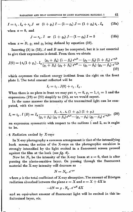
Inserting (3) in (18);A and B may be computed, but it is not essentialto give their expressions in detail. From them we obtain
which expresses the radiant energy incident from the right on the frontplate 1. The total amount reflected will be
When there is no plate in front we may put Tl = 0, el = 1, ti = 1 and theexpressions (19) or (20) simplify to (14), as we would expect.
In the same manner the intensity of the transmitted light can be com-puted, with the result:
-an expression symmetric with respect to the suffixes 1 and 2, as it oughtto be .
. 4 Radiation excited by X-raysIn X-ray photography a common arrangement is that ofthe intensifying
back screen; the action of the X-rays on the photographic emulsion isstrongly intensified by the light excited in a :fluorescent screen pressedagainst the film at the back (see fig. 4).
Now let No be the intensity of the X-ray beam at x = 0, that is afterpassing the photo-sensitive layer. On passing through the :fluorescentmaterial the X-ray intensity will decrease as
N= No.e-p",
where f-l is the total coefficient of X-ray absorption. The amount of Röntgenradiation absorbed between the plane x = X and x = X + dX is
-dN = f1 • No . e-Px dX
and an equivalent amount of :fluorescent light will be excited in this' in-finitesimallayer, viz.

di = k • fl .No . e-Px dX (21)
62 H. C.HAMAKER
the constant k measuring the efficiency of the fluorescence.Transmission of thisvisible light through the fluorescent layer will take
place according to equations (la, b), and the resulting intensity in the planex = 0, that is the light incident on the photographic plate, will now hecomputed.
Fig: 4. A layer of fluorescent material (thickness D) applied to a piece of cardboard, used. as an intensifying back screen in Xvray photography.
Let u~ suppose an amount of light di to be created in the layer dx atx =X, half of which is emitted to the right, the other half to the left.To find the resulting distribution of light intensities the layer must he. divided into two parts, viz: 0 < x <'X and X < x <D. Assuming
1= 11= Al(l- (Jo) ea•x+ Bl(1 + (Jo) e-a,x
J = Jl = Al(1+ (JO) ea,,,+ BI (1 - (Jo) e-a",
when 0 < x < X, and
(22a)
(22b)
I = 12 = A2(1- (Jo) ca", + B2(1 + (Jo) e-a,x
J = J2 = A2(1 + Po) ea,x + B2(1 - (Ju) e-a",
whenX < X <D,
the boundary conditions will he
(22c)
(22d)
11= Tl . Jl or (1 + el) 11- (1 - el) Jl= 0J1= J2 + t di, 12 = 11 + t diJ2 = T2 • 12or (1 + (2) J2 - (1 - t.?2) 12= 0
forx = 0 !forx= Xforx = D
(23)
Tl' el referring to the film and T2, e2 to the cardboard.

RADIATION AND HEAT CONDUCTION IN LIGHT-SCATTERING MATERIAL I 63
By combining (22) and (23) Al' B1, A2, and B2 may be calculated, and withthese we subsequently obtain
J1(0}= A1(1 + {Jo} + B1(1- {Jo}=1 . (e2 + {JO}eu.(D-X) - (e2 - {JO} e-u.(D-Xj
= 1fdL (1 + el) D- -- --- - D (24)(el + {Jo} (e2 + {Jo} eU' - (el - {Jo} (e2 -- {Jo} e-G·
and similarly
12(D)= A2(l - {Jo} eu•D + B2(1 + {Jo} e-G,D =
(n + {J } eU'x ( {J } e-u•x=-}di (1 + e ) -'<::1 po __ -=- (11 - 0 - • (25)
2 (el + {Jo} (e2 + {Jo} eu•D - (el - {Jo} (e2 - flo) e-G·D
for the radiation incident from the right on the photographic plate andfrom the left on the cardboard underlayer respectively. The latter quantityis not of essential interest in our present problem hut has been computedfor the sake of completeness. .To find the resultant intensities under X-ray irradiation we have to
replace di in (24) and ,(25) by the expression (21) and to integrate fromX = P to X = D, with the result:
According to circumstances these formulae can sometimes be simplified.For instance when D is large the terms e-u,D can be disregarded with res-pect to the term eu•D • We shall not consider these questions in detail here;for practical applications we may refer to a paper by Dr Kl.a sen s.An alternative method to treat the same problem is to start from the
differential equations
dl .<Ix = - (a + s) I + sj + .~.C e-PX
dj- = (a + s) J - sI - i C e-PXdx
which are deduced from equations (I) by adding the amount of radiationexcited by the X-rays, half ofwhich contributes to I and the other halfto J.
(28)

64 H. C. HAMAKER
By common principles the general solution of (28) is found to he
(92)
A and B must now be determined by the boundary conditions:
(1 + lh) J - (1 - (h) J = 0(1 + (12) J - (1 - (12) I = 0
whenx = 0,whenx= D.
(30)
That the expressions (26) and (27) result, may readily he verified.It should be mentioned that equations (28) are practically identical with
the equations used by D reo sti 2) in discussing the scattering of lightwhen the layer is illuminated by parallel rays of visible light. Owing toscattering and absorption the incident beam will decrease in intensityas C . e-kx from left to right. When a parallel beam of intensity H passesthe layer dx a fraction p.H.dx will he scattered in the forward direction(positive x) and a fraction q.lI.dx ill the backward direction (negative x).If to this scattered light we apply the principles adopted throughout thispaper we must have
dl-- = - (a + s) I + sJ + qCe-kx ,dx .
dJ= (a + s) J - sI - pCe-kx,
dx
(31)
the only difference from (28) being that the coefficients pand q are une-qual. The solution of (31) ~ illdescribe the amount of diffuse light emanatingfrom both sides of the layer. According to Dreosti's observations thistheory is in good accord with experiments.
5. Temperosure radiatiun
As a last problem we will consider a light-scattering layer heated to auniform temperature and investigate the resulting radiation. .
From the total radiant flux I in the direction of positive x a fractiona.I.dx is absorbed in the layer dx (fig. I). Consequently to conform toKirchhoff's law this layer dx will contribute by radiation the amounta.Eo.dx in the direction of negative x, where Eo designates the black-bodyradiation at the temperature and wavelength in question. The sameamount will 'of course be radiated in the opposite direction. By addingthese quantities to equations (1) we are led to

RADIATION AND HEAT CONDUCTION IN LIGHT·SCATTERING MATERIAL I 65
dl-- = - (a + s) I + sj + aEodx '-
dj-= (a + s) J - - sI - aEo
dx
(32)
which are solved by
1= A(1 - Po) ea,,,+ B(1 + Po} e-a,,,+ EoJ = A(1 + Po} ea?"+ 8(1- Po} e-a,,,+ Eo ..
(33)
If the light-scattering material is applied as a coating on an underlayer ofreflectivity r the boundary conditions will read:
1=0 forx = 0J = r.I + (1-·r) Eo or (1+ e) J - (1- e) 1 = 2eEo for x = IJ, (34)
the term (1- r) Eo representing the radiation contributed by the under-layer according to Kirchhoff's rule. After computing A and B we findfor the temperature radiation
where R is the reflectivity expressed by formula (14). This is again inkeeping with Kirchhoff's law.
Other cases may be worked out in the same manner.
6. The constants a, s, etc.
To conclude this paper we shall briefly recapitulate the data availableconcerning the magnitude of the constants a and s and the derived quan-tities ao and Reo. The most extensive observations were made by Juddand collaborators 7) who checked equation (14) for various ,materials.They computed Reo and s, from which, however, a and a can easily becalculated with the aid of equations (15) and (17). A few characteristicdata have. been collected in table 1. The dental silicate cements, having thelowest value of ao, are most transparent; next come the vitreous enamels,whereas the cold-water paints are very opaque; a coating of these of 0'01to 0'02 cm will suffice to mask the colour of the underlayer almost com-pletely. .
Some further data have been deduced by Dreosti for opal glassesand mast~ emulsions. His results are reproduced in table Il. The opalglass has optical properties of the same order as the dental silicate cementsof J udd, though they are somewhat more opaque. The mastix emulsions

R", scm-1
acm-1
sa
66 H. C. HAUAKER
TABLE I
R"" a and s according to observations by Judd and collaborators
I. Vitreous enamels
0·89 100 0·68 I 1I·7 1470·90 90 0·50 9·5 1800·89 64 0·435 I 7·5 1470·82 56 0·875 9·9 64
u. Cold-water paints (white)
0·88 900 7·35 lIS 1220·86 720 8·20 109 880·93 650 1·72 47·5 380
UI. Dental silicate cements
White 0·76 6·2 0·235 1·72 26·4White 0·50 3·6 0·90 2·70 4·0Light yellow 0·40 3·8 1·71 4·00 2·2Light yellowgrey 0·59 2·1 0·30 1·16 7"0Dark grey 0·16 1·7 3·74 5·15 0·45
-
TABLE II
R"" a and s observed by Dreosti, À = 5370 A
R", scm-1
acm-1
• Go
cm-1sa
1. Opal glasses· various samples,0·807 7·8 0·18 1·69 430·750 18·3 0·76 5·33 240·771 13·6 0·46 3·57 29·50·56 8·0 1·49 4·95 5·7
u. Mastix emulsions
Go
I0·39 I 0·31 0·147 0·336 2·1
G1 0·091 0·22 0·915 1·11 . 0·24G2 0·020 I 0·06 1·12 2·21 0·03
Ko
I0·338
I0·66 0·42 0·85 1·6
Kl 0·176 0·60 1·15 1·64 0·52K2 0·030 0·20 3·00 3·19 0·06
Emulsions K and G both contained 5 g mastix per litre. The average particle diameterwas 0·67 [J. for G and 0·49 [J. for K. In the sequenceKo, Kl' K2 acid fuchsine has been addedto the intermicellar fluid in increasing quantities. The exact concentrations have not beenstated, and the description of the emulsions is, on the whole, rather incomplete.
RADIATION AND HEAT CONDUCTION IN LIGHT SCATTERING MATERIAL I 67
are much more transparent. Unfortunately the description of these emul-sions is incomplete, but it is of interest to note that adding a dye to theHuid not only increases the absorption a but at the same time diminishesthe coefficient of scattering s. This clearly shows how closely these twoconstants are connected;' they are not independent of one another.
Eindhoven, October 1942.
REFERENCES1) A. Schuster, Astrophys. J. 21, 1, 1905.2) G. M. Dr eost i, Thesis, Utrecht 1930.3) P. Kubelka & F. Munk, Z. tech. Phys. 12, 593, 1931.4) J. Spijkerboer, Thesis, Utrecht 1917.5) K. Schwarzschild, Berl. Ber. 1914, p. lI83.6) L. V. King, Phil. Trans. Roy. Soc. London A 212, 375, 1912.7) D. B. Judd & collaborators, Bur. Stand. J. Res. 19, 317, 1937.
ABSTRACTS'(Continued from page 54)
1696: J. F. H. Custers and J. C. Riemersma, The texture of straight-rolled and of cross-rolled molybdenum, Physica 's-Grav.12, 195-208,1946. .
With the aid of pole figures the textures of straight-rolled and of cross-rolled molybdenum are determined. The pole figures thus obtained showthat earlier authors described these textures in a too simple way; they areat least twofold.For example, after cross-rolling, there is found besides the so-called (100)
[HO] tecture ((~OO)parallel to the rolling plane, and [110] parallel to therolling direction) a second texture, which is rotary symmetrical around thenormal to the rolling plane, and which has a (111) plane parallel to this plane.The texture of straight-rolled molybdenum turns out to be in good
agreement with the texture of straight-rolled iron, as determined byK urdjumow and Sachs; the texture of cross-rolled iron is not known.
1697: N. G. de Bruijn, A combinatorial problem, Proc. Kon. Ned.Akad. Wetenschappen Amsterdam 49, 758-764, 1946.
A Pn-cycle is defined as an ordered cycle of 2n digits 0 or 1 (i.e. a seriesof such digits placed on the circumference of a circle), such that the 2n
possible sets of n consecutiv~ digits of that cycle are all different '(as aconsequence, any ordered set of n digits 0 or 1occurs exactly once in thatcycle). Posthumus studied these cycles in connection with a practicalproblem of telecommunication, and was led to the conjecture, that thenumber of Pn-cycles be equal to 2N where N = 2n-I_n. This conjectureis proved to be correct, as follows from a theorem concerning a specialtype of networks. Another application of this theorem is mentioned too.
(Continued on page 79)