Radiant / Convector Gas Fire - Boiler...
11
5112107/02 This guide to be left with the owner OWNER GUIDE Model 347 Radiant / Convector Gas Fire Fitted with one of the following fascia Brava 4 Oxysafe Charm 4 Oxysafe or Esquire 4 Oxysafe (G. C. Number 32-032-62) THIS APPLIANCE IS FOR USE WITH NATURAL GAS (G20) THIS APPLIANCE IS SUITABLE ONLY FOR INSTALLATION IN THE UNITED KINGDOM (GB) AND THE REPUBLIC OF IRELAND (IE) ONLY. We trust that this guide gives sufficient details to enable the appliance to be operated and maintained satisfactorily. However, if further information is required, our Baxi Fires Division Technical Helpline will be pleased to help. Please telephone 08706 061 065 (National call rates apply in the United Kingdom). In the Republic of Ireland telephone 0044 8706 061 065. © Baxi Heating U.K. Ltd.
Transcript of Radiant / Convector Gas Fire - Boiler...

5112107/02
This guide to be left with the owner
OWNER GUIDE
Model 347Radiant / Convector Gas Fire
Fitted with one of the following fascia
Brava 4 OxysafeCharm 4 Oxysafe
orEsquire 4 Oxysafe
(G. C. Number 32-032-62)
THIS APPLIANCE IS FOR USE WITH NATURAL GAS (G20)THIS APPLIANCE IS SUITABLE ONLY FOR INSTALLATION IN THE UNITED
KINGDOM (GB) AND THE REPUBLIC OF IRELAND (IE) ONLY.
We trust that this guide gives sufficient details to enable the appliance to be operatedand maintained satisfactorily. However, if further information is required, our
Baxi Fires Division Technical Helpline will be pleased to help.Please telephone 08706 061 065 (National call rates apply in the United Kingdom). In
the Republic of Ireland telephone 0044 8706 061 065.
© Baxi Heating U.K. Ltd.

Safety First.Baxi Fires Division fires are CE Approved and designed to meet the appropriate British
Standards and Safety Marks.
Quality and Excellence.At the heart of every Baxi Fires Division fire.
All Baxi Fires Division fires are manufactured to the highest standards of quality andexcellence and are manufactured under a BS EN ISO 9001 quality system accepted by
the British Standards Institute.
The Highest StandardsBaxi Fires Division is a member of the Society of British Gas Industries which works to
ensure high standards of safety, quality and performance.
Careful InstallationBaxi Fires Division is a CORGI registered company. All our gas fires must be
installed by a competent CORGI Registered Installer in accordancewith our Installer Guide and should not be fitted directly on to a
carpet or floor of combustible material.
Baxi Fires Division, Erdington, Birmingham B24 9QPwww.firesandstoves.co.uk
Because our policy is one of constant development and improvement, details may vary slightly from thosegiven in this publication
Page 2
OWNER GUIDE

LIST OF CONTENTSSection PageSAFETY 3APPLIANCE DIMENSIONS 5GAS CONSUMPTION 6OPERATING YOUR FIRE 6The Oxysafe flame sensing and flue blockage safety system. 6To light the fire (Manual ignition). 6To light the fire (Electronic ignition). 7CLEANING YOUR FIRE 8REPLACING THE RADIANTS 8MAINTENANCE 9Battery replacement (Electronic ignition). 9Regular maintenance. 10Servicing. 10USEFUL TELEPHONE NUMBERS 11
This gas fire is designed to meet the most stringent quality, performance and safetyrequirements to provide you with many years’ trouble-free service.This guide aims to improve your understanding and appreciation of your gas fire byproviding simple and informative instructions to ensure that you benefit from theexcellent performance and features it has to offer.
SAFETY
Do have the fire installed by a competent person. In the United Kingdom, installationmust be in accordance with the latest edition of the Gas Safety (installation & use)Regulations. In the Republic of Ireland, installation must be in accordance with all
Page 3
OWNER GUIDE
IF YOU SMELL GASDON’T SMOKEEXTINGUISH ALL NAKED FLAMESDON’T TURN ELECTRICAL SWITCHES ON OR OFFTURN OFF THE GAS SUPPLY AT THE METEROPEN DOORS AND WINDOWS TO GET RID OF THE GASIMMEDIATELY CALL THE GAS EMERGENCY SERVICE – SEE YOUR LOCAL TELEPHONEDIRECTORY

national and local regulations in force. Do have the chimney swept prior to installation if it was previously used for solid fuel.Do have the fire installed in accordance with the installation instructionsDo allow a minimum clearance of 90mm from the top of the appliance fascia to theunderside of any shelf whether it is made from combustible or non-combustiblematerials. This clearance is necessary to allow the fascia to be lifted off for servicingand also allows sufficient access to operate the control knob. For a shelf made fromwood or other combustible materials deeper than 150mm add 12.5mm to the clearancefor every 25mm of additional shelf depth (See graph 1). Please bear this in mind if everyou add a shelf.
Do provide a suitable guard that complies with BS 8423 for the protection of youngchildren, the elderly and the infirm. Such a guard is also recommended for the protectionof pet animals. (Although this fire conforms to all the applicable standards, it is a heatingappliance and certain parts of its surface will become hot).Note: The guard supplied with the fire acts as a fireguard conforming to BS1945:1971and satisfies the Heating Appliance (Fireguard) (Safety) Regulations 1991.Do wait three minutes before attempting to relight if the fire is switched off or theflames are extinguished for any reason. (Your fire is fitted with a safety device that willautomatically shut off the gas supply to the fire if, for any reason, the flames go out.) Do get advice about the suitability of any wall covering near your fire. Soft wallcoverings (e.g. embossed vinyl, etc.) which have a raised pattern are easily affected byheat. They may, therefore, scorch or become discoloured when close to a heatingappliance. Please bear this in mind whenever you are considering redecorating.Do provide a minimum clearance of 50mm between the fascia sides and any corner wall
Page 4
OWNER GUIDE
Graph 1 Shelf clearances

having combustible material or other combustible surface which projects beyond thefront of the fire (See figure 1). Please bear this in mind if ever you are consideringaltering the room.
Don’t hang clothing, towels or any other fabrics over the fire.Don’t fill in the space behind the fascia.Don’t use the fire without the dress guard being in position.Don’t attempt to clean or service the fire until it has been switched off and allowed tocompletely.Don’t use the fire with damaged radiants.
APPLIANCE DIMENSIONS
Page 5
OWNER GUIDE
Figure 1. Dimensions and clearances
Model Dimension ‘A’ (mm) Dimension ‘B’ (mm) Dimension ‘C’ (mm)Brava 609 713 177Charm 609 713 177Esquire 609 708 177
GAS CONSUMPTION
Has a maximum natural gas input of 5.6kW (Gross)Has a maximum natural gas output of 4.0kW
Has a minimum natural gas input of 1.57kW (Gross)Has a minimum natural gas output of 1.0kW
OPERATING YOUR FIRE
The Oxysafe flame sensing and flue blockage safety system.For your safety, this appliance is fitted with a flue blockage safety device that will shutdown the appliance in the event of abnormal flue conditions. This device is NOT asubstitute for an independently mounted Carbon Monoxide detector. The device will also automatically shut off the gas supply to the fire if the pilot flamegoes out due to lack of oxygen or for any other reason.If this device starts to repeatedly shut off the gas, get expert advice.This device incorporates a probe that senses that the heat from the pilot flame is correct.If this probe is cool, the device will prevent any gas flow unless the control knob is helddown at the ignition position.If, for any reason, the flames go out when the fire is hot or if the fire is turned off whenhot, always wait at least three minutes before attempting to relight.
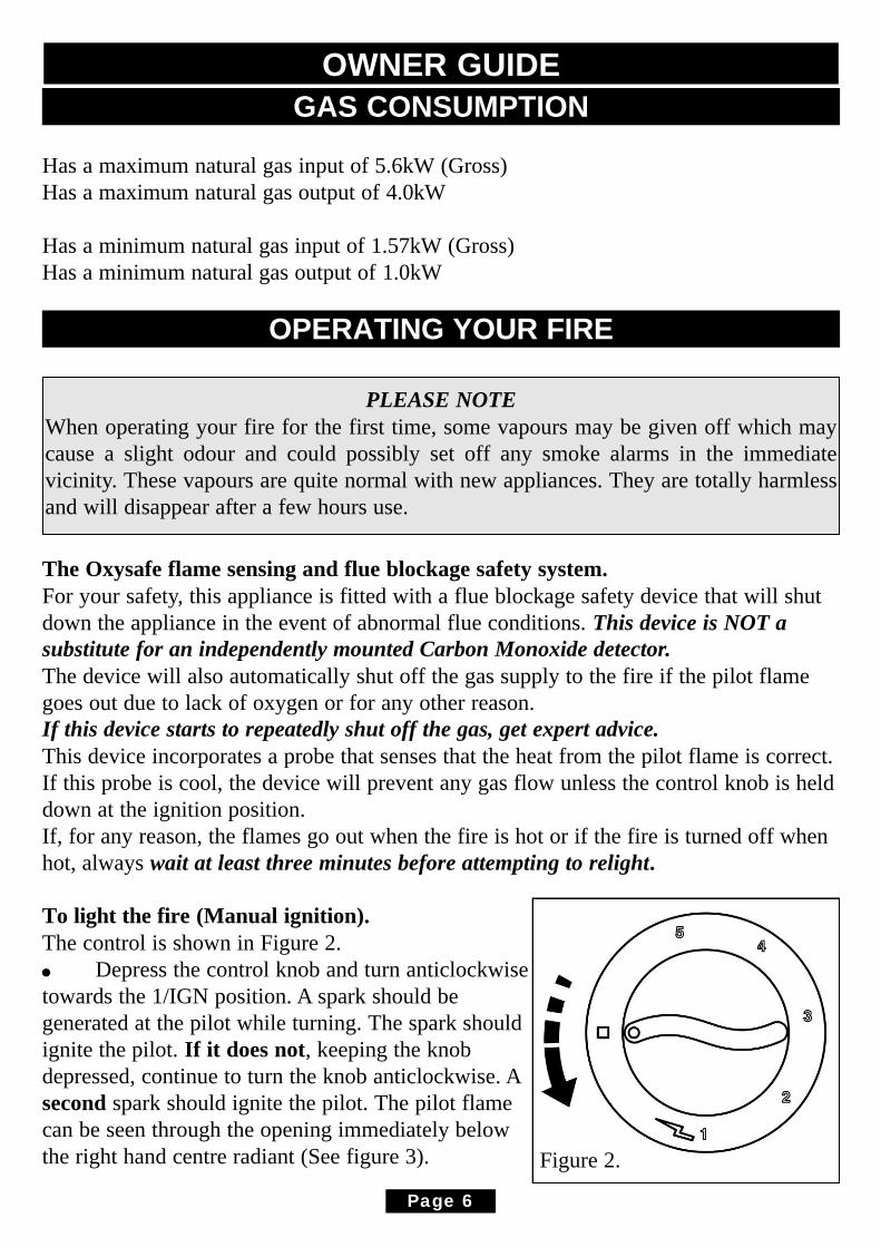
To light the fire (Manual ignition).The control is shown in Figure 2.! Depress the control knob and turn anticlockwisetowards the 1/IGN position. A spark should begenerated at the pilot while turning. The spark shouldignite the pilot. If it does not, keeping the knobdepressed, continue to turn the knob anticlockwise. Asecond spark should ignite the pilot. The pilot flamecan be seen through the opening immediately belowthe right hand centre radiant (See figure 3).
Page 6
OWNER GUIDE
PLEASE NOTEWhen operating your fire for the first time, some vapours may be given off which maycause a slight odour and could possibly set off any smoke alarms in the immediatevicinity. These vapours are quite normal with new appliances. They are totally harmlessand will disappear after a few hours use.
Figure 2.

If the pilot does not light, turn the knob back to OFF and try again.In the unlikely event of failure of the ignition mechanism the pilot can be lit with along match or taper – See the next page.! When the pilot has lit keep the knob depressed for about ten seconds to allow theflame sensing probe to warm up.The control knob can then be set to your preferred heat level. The settings are shown onthe table opposite.
To light the fire (Electronic ignition).The control is shown in figure 2.! Depress the control knob slightly and turn anticlockwise towards the 1/IGNposition. Do not apply too much pressure as this will cause resistance to be felt. Depressthe control knob. Sparks should be generated at the pilot. The sparks should ignite thepilot. If the pilot does not light, turn the control knob back to the‘OFF’ position and tryagain. The pilot flame can be seen through the opening immediately below the righthand centre radiant (See figure 3).
If no sparks are generated at the pilot the battery may have no power. The battery canbe replaced as shown later in this guide.In the unlikely event of failure of the ignition mechanism or where a replacementbattery is not available the pilot can be lit with a long match or taper – See next page.
! When the pilot has lit keep the control knob depressed for about ten seconds to allow the flame sensing probe to warm up.
! The control control knob can then be set to your preferred heat level. The settings are: -
To turn off partially depress the knob and turn clockwise to off. Wait at least threeminutes before attempting to relight.
Page 7
OWNER GUIDE
Control Knob Position Radiants Condition
2
Centre radiants on low. Outer radiants off.(The right hand centre radiant will glow slightlymore than than the left hand centre radiant dueto the pilot flame)
3 Centre radiants fully on. Outer radiants off.4 Centre radiants fully on. Outer radiants on low.5 All radiants fully on.

Lighting with a match or taper.
Manual ignition: Depress the control knob andturn anticlockwise towards the 1/IGN position.Electronic ignition: Depress the control knobslightly and turn anticlockwise towards the1/IGN position.
While keeping the knob depressed, light the pilotby inserting a long match or taper into theopening shown in figure 3 (Second opening fromthe right).When the pilot is alight, keep the knob depressedfor about ten seconds to allow the flame sensingprobe to warm up before setting to your preferredheat level.For your own convenience, have the heaterserviced as soon as possible.
CLEANING YOUR FIRETurn the fire off and allow it to cool before attempting any cleaning.Normally the fire will only need dusting. The bright metal trims may be cleaned with adamp cloth and dried with a soft duster. Obstinate marks can be removed from the guardand trims using soapy water. Never use abrasive cleaners.The radiants can be cleaned with a soft brush - see below for how to remove theradiants.
REPLACING THE RADIANTS(See figure 4).
Always use the correct type of replacement radiant. Ask for Baxi Fires Divisionpart number 5110472. Turn the fire off and allow it to cool before attempting toremove the radiants.To remove the dress guard, gently pull the centre of the dress guard with one hand andcarefully spring out one end of the dress guard with the other. Slide the other side of thedress guard clear of the fixing holes. Take care not to scratch the trim.
Page 8
OWNER GUIDE
Figure 3.

Lift the radiant upward to clear themetal retaining bar then pull outbottom first.Fit the new radiant by inserting its topunder the top lip of the radiant boxthen swing the bottom of the radiantover and behind the retaining bar. It isimportant that the front face of theradiant should rest against the frontof the retaining channel. Replace thedress guard. To do this locate one sideof the dress guard into the two sidefixing holes. Spring the dress guardslightly and locate into the oppositefixing holes. Take care not to scratchthe trim.
MAINTENANCE
Battery replacement (Electronic ignition).1. The battery cover is located at the base of the fire on the right hand side. 2. To access the battery cover the fascia will have to be removed. The fascia securingscrews are located at the bottom rear of the fascia. Remove the securing screws fromboth sides of the fascia.3. Remove the control knob. To do this firmly hold the control knob and lift clear of thefascia.4. The fascia can now be removed. To do this firmly hold the fascia sides, gently pullthe bottom of the fascia forward whilst lifting the fascia upward and forward. Place thefascia in a safe place.5. Unscrew the battery cover in an anticlockwisedirection.6. Remove the battery and discard.8. Remove any protective film from thereplacement battery and place into the generator.The negative ( - ) terminal should go in first. Thecap of the generator is marked with ( + ).9. Refit the battery cover. 10. Place the fascia over the engine. Make surethat the top rear of the fascia locates fully into the
Page 9
OWNER GUIDE
Figure 4.
Figure 5. Fascia top location
‘U’ shaped notch of the engine back panel (See figure 5).11. Fit the control knob firmly on to the control spindle.12. Secure the fascia using the two screws previously removed. There are two holes inthe fascia. Use the bottom hole.
Regular maintenance.In order to achieve and maintain high levels of personal safety and performanceefficiency, it is essential that the opening at the back of the fire and the flue are keptclear of any form of obstruction. It is possible that deposits of mortar or soot could falland accumulate causing the flue to be blocked or restricted and so preventing properclearance of dangerous exhaust fumes.In the United Kingdom it is the law that a landlord must have any gas appliance, flueand pipework which is situated in a tenant’s premises checked for safety at least everytwelve months by a competent person (In the U.K., a CORGI registered installer).We recommend that all gas appliances and their flues, wherever situated, are checkedannually.
Servicing.! Servicing can be carried out either by a Baxi Fires Division Service engineer or a CORGI registered installer.! If you require your fire to be serviced, please contact Baxi Fires Division Serviceon 08706 090 081
IMPORTANTTo help us quickly help you, please try to have the following information availablebefore you contact us:! Type of fire.! Model/Name.! Serial Number.You will also be asked for the fault, problem or request plus your Post Code.
! If you wish to replace the radiants, spare parts are available nationwide via the‘interpart stockist network’. For your local stockist consult Yellow pages under CentralHeating.
! When fitting replacement parts it is important that only Baxi Fires Divisionapproved parts are used for maximum safety.
Page 10
OWNER GUIDE
USEFUL TELEPHONE NUMBERSGeneral advice about gas and your gas fire:BAXI FIRES DIVISION TECHNICAL HELPLINE 08706 061 065.
To report faults or arrange for your fire to be serviced:BAXI FIRES DIVISION SERVICE 08706 090 081.
For sales or product information:BAXI FIRES DIVISION SALES 08706 061 067.
For spares inquiriesSpare parts are available nationwide via the ‘interpart stockist network’. For yourlocal stockist consult Yellow pages under ‘Central Heating’.
CALLERS IN THE REPUBLIC OF IRELANDCall 0044 8706 061 065
Page 11
OWNER GUIDE