Radiant Bruciatorisliminstruction99943na
24
CE 0694 ENGLISH Technical Specification RADIANT BRUCIATORI S.p.A. Montelabbate (PU) ITALY By Technical Department INSTALLATION, AND MAINTENANCE MANUAL FOR GAS FIRED, WALL-HUNG BOILERS Model RSF 20 E – RSF 24 E TYPE C ROOM SEALED
Transcript of Radiant Bruciatorisliminstruction99943na
CE 0694 ENGLISH
Technical Specification RADIANT BRUCIATORI S.p.A. Montelabbate (PU) ITALY By Technical Department
INSTALLATION, AND MAINTENANCE MANUAL FOR GAS FIRED, WALL-HUNG BOILERS
Model RSF 20 E – RSF 24 E TYPE C ROOM SEALED


INDEX INSTALLATION INSTRUCTIONS AND WARNINGS page 1 TECHNICAL DATA page 2 OVERALL DIMENSIONS - EXHAUST FLUE SYSTEM page 3 GENERAL INSTALLATION REQUIREMENTS page 4 BOILER INSTALLATION page 6 ELECTRICAL CONNECTIONS page 8-16-17 BOILER CONTROL PANEL page 8 STARTING UP THE BOILER FOR THE FIRST TIME page 9 BOILER ADJUSTMENTS page 11 GAS TYPE CONVERSION page 12 REGULATING THE GAS PRESSURE page 13 MAIN COMPONENTS page 14-15 MAINTENANCE page 18 UNPACKING page 18 FAULT FINDING CHART page 19 SHORT LIST OF COMPONENTS page 20

Installation Manual
Combi - cod. 99943NA – November 2002 1
THE FRIENDLY POWER OF HEAT Thank you for choosing RADIANT Declaration for purposes of Art. 7 of Law 46 of 5 April 1990. RADIANT BRUCIATORI S.p.A. hereby declares that all of its products are constructed to industry standards as required by the Article in question and by Article 5 of the law in effect (D.P.R. no. 447/97). RADIANT BRUCIATORI S.p.A. products are type tested EC. All RADIANT boilers are constructed according to UNI - CIG (EC) norms. The materials used, such as copper, brass, and stainless steel form a compact, homogeneous, highly functional unit that is easy to install and simple to operate. The wall-mounted boiler is equipped with all of the approved accessories required to make it a true, independent heating plant for home heating and for the production of hot water for domestic needs. All boilers are fully inspected, and come with a certificate of quality signed by the inspector and with a warranty certificate. This booklet must be read carefully and stored in a safe place, accompanying the boiler at all times. RADIANT BRUCIATORI S.p.A. declines any and all responsibility for misinterpretations of this booklet deriving from any translations of same. RADIANT BRUCIATORI S.p.A. will not be responsible for non-observance of the instructions contained in this booklet or for the consequences of any action not specifically described herein.
INSTALLATION INSTRUCTIONS - WARNINGS THIS INSTALLATION, USE, AND MAINTENANCE MANUAL IS AN ESSENTIAL AND INTEGRAL PART OF THE PRODUCT, AND MUST ALWAYS BE KEPT NEAR THE DEVICE. THE WARNINGS CONTAINED IN THIS SECTION ARE ADDRESSED BOTH TO THE USER AND TO INSTALLATION AND MAINTENANCE PERSONNEL. THE USER WILL FIND INFORMATION ON OPERATION AND LIMITS OF USE IN THE ACCOMPANYING MANUAL, WHICH SHOULD BE READ VERY CAREFULLY. STORE THE MANUAL CAREFULLY FOR FUTURE REFERENCE. 1) GENERAL WARNINGS INSTALLATION MUST BE PERFORMED IN OBSERVANCE OF CURRENT NORMS, ACCORDING TO THE CONSTRUCTOR’S INSTRUCTIONS, AND BY PROFESSIONALLY QUALIFIED PERSONNEL. THE INSTALLATION INSTRUCTIONS MANUAL MUST BE ALWAYS ACCOMPANY THE BOILER. PROFESSIONALLY QUALIFIED PERSONNEL ARE THOSE HAVING TECHNICAL COMPETENCE IN THE SECTOR OF APPLICATION OF THE DEVICE (CIVIL OR INDUSTRIAL), AND, IN PARTICULAR, THE CONSTRUCTOR’S AUTHORISED SERVICE CENTRES. INCORRECT INSTALLATION MAY CAUSE DAMAGE TO PERSONS, ANIMALS, OR PROPERTY, FOR WHICH THE CONSTRUCTOR ASSUMES NO LIABILITY. • After completely removing the packing, make sure that the contents are in perfect condition. • In case of doubt, do not use the equipment. Consult the supplier. • Packing materials (cardboard carton, wooden crate, nails, clips, plastic bags, polystyrene, etc.) are potentially dangerous and must be kept away from children. • Before performing any cleaning or maintenance operation, turn off the unit by means of the mains switch and/or by means of the appropriate cut-off devices. • Do not block the air intake or heat dissipation grates. • In the event of breakdown and/or poor functioning of the device, turn it off and do not attempt to repair it or take any direct action. Refer to professionally qualified personnel only. • Any repairs must be performed exclusively by a service centre authorised by the constructor, and with original spare parts only. • Non-observance of the above instruction may compromise the safety of the device. To guarantee efficient and correct operation, the device should undergo period maintenance by professionally qualified personnel according to
the constructor’s instructions. • Whenever the device is to be put out of service, secure all potentially hazardous parts to prevent accidents or damage. • If the device is sold or transferred to another owner, or if you move and leave the boiler, make sure that this booklet stays with the boiler so that it may be consulted by the new owner and/or by the installer. • Use only original spare parts for all devices with optionals or kits (including electrical ones). WARNING: this device must be used for its intended purpose, i.e., heating and production of domestic hot water. Any other use is improper and therefore dangerous. The constructor will have no contractual or extracontractual liability for damage caused by incorrect installation and/or use or by non-observance of instructions supplied by the constructor. This device must be used exclusively with a sealed central heating system equipped with an expansion vessel. 2) WARNINGS REGARDING INSTALLATION Warranty expires 12 months from date of installation and in all cases no later than 18 months from date of construction. First start-up must be performed by authorised personnel only. For any operation on the hydraulic, gas, or electrical circuit regarding the heating unit, refer to authorised technicians only and use original spare parts only. Wall-mounted boilers are not to be installed in damp rooms, and must be protected against sprays or jets of water or other liquids to prevent malfunctions of the electrical and heating devices. They must not be exposed to direct steam from cookers, and nothing must be placed on top of them. This heating unit has been constructed to heat the home and to produce hot water. The constructor declines all responsibility for incorrect installation and/or use of the device. Do not leave the device on when it is not being used: close the gas cock and turn off the mains switch. If you smell gas in the room in which the device is installed, do not operate any electrical switches, telephones, or any other device that might cause a spark. Immediately open doors and windows to create an air current to clear the room. Close the main gas cock (at the meter) or the cylinder cock, and request immediate technical service. Do not tamper with the device.
SYSTEMS WITH THERMOSTATS A by-pass must be installed in heating systems with radiators thermostats. As required by current norms, these devices must be installed by qualified personnel only, who must respect norms UNI-CIG 7129 and 7131 and revisions, fire department regulations, and requirements of the local gas company. Before installing the boiler, make sure that the water and heating systems are compatible with its output. The room must be properly ventilated by means of an air intake (see UNI 7129/92 and UNI 7129/95 FA). The air intake must be at floor level open flue only, at a point where it cannot be obstructed, and protected by a grate that does not reduce the useful section of flow. The use of air flows from adjacent rooms is permitted as long as such rooms are in depression with respect to the outside and as long as there are no wood-burning fireplaces or fans installed there. If the boiler is to be installed externally (for example, on balconies or terraces), make sure that it is protected against atmospheric agents to prevent damage to components and voiding of the warranty. In such cases we recommend building a heat compartment to protect the boiler against inclement weather. Check the technical data on the packing and on the plate located inside the front casing. Check that the burner is suitable for use with the type of gas available. Make sure that all pipes and connections are perfectly sealed and that there are no gas leaks. All pipework should be chemically flushed to remove any residues that might negative effect the operation of the boiler. 3) GENERAL WARNINGS BASED ON TYPE OF POWER SUPPLY POWER SUPPLY Electrical safety is achieved only when the device is correctly and efficiently earthed as per current safety norms (IEC 64-8 Electrical Part). • This fundamental safety requirement must be checked. In case of doubt, request a check of the electrical system by professionally qualified personnel. The constructor will not be liable for any damage caused by lack of or
improper earthing of the system. • Have professionally qualified personnel check that the electrical system is adequate for the maximum absorbed power of the device (indicated on the plate). In particular, make sure that the section of the system wires is
suitable for the maximum absorbed power of the device. • Do not use adapters, multiple sockets, and/or extension cords to power the device from the electrical mains. • Provide a unipolar switch as required by current safety regulations to connect the device to the mains. • The use of any electrical device requires the observance of some fundamental rules, such as: • do not touch the device with wet or damp parts of the body and/or with bare feet • do not pull on electrical cables • do not expose the device to atmospheric agents (rain, sun, etc.) unless specifically provided for • do not allow the device to be used by children or anyone unfamiliar with its operation • The power cable must not be replaced by the user. • If the cable becomes damaged, turn off the device and have the cable replaced by professionally qualified personnel only. • If you decide not to use the device for an extended length of time, turn off the mains switch that feeds all components of the system using electrical energy (pumps, burner, etc.).

Installation Manual
Combi - cod. 99943NA – November 2002 2
TECHNICAL DATA
Type C unit Type C devices are devices in which the combustion circuZ it (air intake, combustion chamber, exchanger, combustion exhaust) is sealed off from the place where they are installed. CENTRAL HEATING - DOMESTIC HOT WATER sealed combustion circuit type RSF 20 E - electronic ignition RSF 24 E - electronic ignition
Technical data
MODEL RSF 20 E RSF 24 E Maximum rated input KCal/h 22900 25628 Kw 26.6 29.8 BTU/h 90867 101692 Minimum rated input KCal/h 11000 15000 Kw 12.8 17.5 BTU/h 43648 59250 Maximum rated output KCal/h 20900 23090 Kw 24.34 26.85 BTU/h 82931 91621 Minimum rated output KCal/h 9450 12900 Kw 11 15 BTU/h 37498 51187 Heating temperature adjustment °C 30-80 30-80 Max. working pressure (heating) bar 3 3 Min. working pressure (heating) bar 0.3 0.3 Expansion vessel capacity (initial pressure 1 bar) Litres 8 8 Hot water flow rate ∆t 25° Litres 13 15 Max. working pressure (water) bar 6 6 Min. working pressure (water) bar 0.5 0.5 Width mm. 450 450 Height mm. 860 860 Depth mm. 345 345 Weight Kg. 49 49 Coaxial exhaust flue diameter Double exhaust flue diameter 100/60
80/80 100/60 80/80
Flow/return connections Ø 3/4” - 3/4” 3/4” - 3/4” Cold water connections Ø 1/2” 1/2” Hot water connections Ø 1/2” 1/2” Gas connections Ø 1/2” 1/2” Electrical connection 50 Hz V 230 230 Power supply W 170 170 Burner jets NP 13 G30 Ø 1.25 1.25 Burner jets NP 13 G30 Ø 0.75 0.77 Gas category: IT II2H3 Gas supply pressure: G20 20 mbar / G30/31 29-30/37 mbar
FORCED CIRCULATION
Coaxial vertical Coaxial horizontal
C32C12
C52 Double

Installation Manual
Combi - cod. 99943NA – November 2002 3
TYPE C WALL-MOUNTED BOILERS SEALED COMBUSTION CIRCUIT: Kit A Horizontal coaxial exhaust flue system with 360° rotation. It allows the flue exhaust and the air intake directly to an external wall. . To insert a bend, reduce total flue length by 0.8 m. Kit B Double exhaust/emission twin flue system with 360° rotation. It allows the flue exhaust into a flue duct and the air intake directly from an external wall. To insert a bend, reduce total flue length by 1.5 m. R RETURN ¾” G GAS ½” C HOT WATER ½” F COLD WATER ½” A HEATING FLOW ¾”
NOTE: USE ORIGINAL RADIANT APPROVED FLUE KIT SYSTEMS, FLUE ACCESSORIES AND FLUE DIAPHRAGMS ONLY. APPROVED RADIANT FLUE DIAPHRAGMS AND ADJUSTMENT TABLES ARE SUPPLIED WITH RADIANT ORIGINAL FLUE KIT SYSTEMS.
46
46101R
51 7378G C
101F A
225
796
760
80
85
331
280
120
85
80
10151R
796
760
85
7378G C
101F A
280
331
85
60 100 450
= =
220
56
26 26 155
860
981
80
345
1007
860
220
26
860
928
2656
60 100
954
860

Installation Manual
Combi - cod. 99943NA – November 2002 4
GENERAL INSTALLATION REQUIREMENTS GAS SAFETY It is the law that all gas appliances are installed by a CORGI registered installer (you can check this by contacting corgi on 01256.372200) in accordance with the regulations listed below. Failure to install appliances correctly could lead to prosecution. It is in your own interest and that of safety to ensure that the law is complied with. Failure to have your appliance installed to comply with the installation instructions and the requirements listed below could invalidate your guarantee. RELATED DOCUMENTS The installation of the boiler must be in accordance with the relevant requirements of the Gas Safety regulations, Building regulations, I.E.E. regulations and the bylaws of the local water authority. It should be in accordance also with any relevant requirements of the local authority and the relevant recommendations of the following British Standard Codes of Practice: B.S 6400: 1985 & B.S. 6891 : 1988. BS 5376: Selection and Installation of Gas Space Heating ( 1 and 2 family gases) Part 2: Boilers of rated input not exceeding 60 Kw BS 5449: Central Heating for domestic premises Part 1: Forced circulation Hot Water System CP 342: Centralised Hot Water Supply BS 6700 : 1987 Part 2: Buildings other than individual BS 5440: Flues and air supply for Gas Appliances of rated input not exceeding 60 Kw (1 and 2 family gases) Part 1: Flues Part 2: Air Supply BS 5446: 1990: Installation of Gas Hot Water supplies for domestic purposes GAS SUPPLY Service Pipes: The local gas region should be consulted at the installation planning stage in order to establish the availability of supply of gas. An existing service pipe must not be used without prior consultation with the local gas region. Meters: A gas meter is connected to the service pipe by the local gas region or local gas region contractor. An existing meter should be checked to ensure that it is capable of passing an additional 3.4 m3/hr (125 ft/hr) before the appliance is installed. The meter outlet governor should ensure a nominal dynamic pressure of 20m Bar, (8 in wg) at the boiler. Installation pipes should be fitted in accordance with BS6891.1988. Pipework that supplies the boiler must be a 22 mm. ininterrupted supply from meter to the isolation cock of the boiler. The complete installation must be tested for soundness as described in the above code, BS 6400: 1985 & BS6891. IMPORTANT: BOTH THE USER AND THE MANUFACTURER RELY UPON THE INSTALLER, WHOSE JOB IS TO INSTALL THE BOILER AND CONNECT IT TO A CORRECTLY DESIGNED HEATING SYSTEM. THE INSTALLER SHOULD ACQUAINT HIMSELF WITH THE CONTENTS OF THIS PUBLICATION AND THE RELEVANT BRITISH STANDARDS CONCERNING INSTALLATION REQUIREMENTS. LOCATION OF BOILER In siting the combination boiler, the following limitations MUST be observed: The position selected for installation should be within the building, and MUST allow adequate space for installation, servicing and operation of the combination boiler, and for air circulation around it. The boiler is not suitable for external installation. This position MUST also allow for a suitable flue termination to be made. The boiler must be installed on a flat vertical wall which is capable of supporting the weight of the combination boiler, and any ancillary equipment. If the boiler is to be fitted in a timber framed building it should be fitted in accordance with the British Gas publication "Guide for Gas Installations in Timber Frame Housing, Reference IGE/UP/6. If in doubt, advice must be sought from the local region of British Gas. The boiler may be installed in any room or internal space, although particular attention is drawn to the requirements of the current I.E.E. Wiring Regulations, and in Scotland the electrical provisions of the Building Regulations applicable in Scotland, with respect to the installation of the boiler in a room or internal space containing a bath or shower. Where a room-sealed appliance is installed in a room containing a bath or shower, any electrical switch or appliance control utilising mains electricity must be so situated that it cannot be touched by a person using the bath or shower. A compartment used to enclose the combination boiler MUST be designed and constructed specifically for this purpose. An existing cupboard, or compartment, may be used provided it is modified accordingly. Where installation will be in an unusual location, special procedures may be necessary. BS 6798 gives detailed guidance on this aspect. For clearances to be made available for installation and servicing, see Sections 5.2.2. to 5.2.4.

Installation Manual
Combi - cod. 99943NA – November 2002 5
FLUE POSITION IMPORTANT: THE FLUE SYSTEM SHALL BE INSTALLED IN ACCORDANCE WITH THE RECOMMENDATIONS CONTAINED IN BS 5440:1. The boiler MUST be installed so that the terminal is exposed to the external air. It is important that the position of the terminal allows free passage of air across it at all times. If the terminal discharges into a pathway or passageway check that combustion products will not cause nuisance and that the terminal will not obstruct the passageway. In certain weather conditions a terminal may emit a plume of steam. Positions where this would cause a nuisance should be avoided. IMPORTANT REQUIREMENT: The correct dimensional relationship between the terminal and any obstruction, openable window or ventilator as shown in Fig 1 pag.7 It is ESSENTIAL TO ENSURE, in practice, that products of combustion discharging from the terminal cannot re-enter the building, or any other adjacent building, through ventilators, windows, doors, other sources of natural air infiltration, or forced ventilation/air conditioning systems. If this should occur, the appliance MUST BE TURNED OFF IMMEDIATELY and the local gas region consulted. Where the lowest part of the terminal is fitted less than 2m (6.6ft) above a balcony, above ground, or above a flat roof to which people have access, the terminal MUST be protected by a purpose designed guard. Where the terminal is fitted within 850mm (34in) of a plastic or painted gutter, or 450mm (18in) of painted eaves, an aluminium shield of at least 1000 mm (40in) long should be fitted to the underside of the gutter painted surface. The air inlet/products outlet duct and the terminal of the boiler MUST NOT be closer than 25mm (1in) to combustible material. TERMINAL POSITION
J
E A
G
M
F F
AD H,I
TOP VIEW REAR FLUE
D
G
L
K
G
NB.C
TERMINAL ASSEMBLY
PROPERTY BOUNDARY LINE
300 min
A Directly below an openable window, air vent or any other ventilation opening. 300 mm B Below gutter, drain pipes or soil pipes. 25 mm C Below eaves. 25 mm D Below balcony or carport roof. 25 mm E From vertical drain pipes or soil pipes. 25 mm F From internal or external corners. 25 mm G Above adjacent ground, roof or balcony level. 300 mm H From a surface facing the terminal. 600 mm I Facing the terminals. 1200 mm J From opening (door, window)in the carport into dwelling. 1200 mm K Vertically from a terminal on the same wall 1500 mm L Horizontally from a terminal on the same wall 300 mm M Above an opening, air brick, opening window etc. 300 mm N Horizontally to an opening, air brick, opening window etc. 300 mm
Fig. 1

Installation Manual
Combi - cod. 99943NA – November 2002 6
COLD WATER INLET
R
G
FA
R
CG
R
HOT WATER OUTLET
RETURN
FLOW
GAS
G
C
F A
C
F
A
Fig. 3
MINIMUM DISTANCES FOR FIXING TO WALL
To allow access in the boiler for maintenance operations, the minimum distances shown below must be respected (fig. 1): To facilitate installation, the boiler is supplied with a template for advance location of connections to pipes. In this way, you may simply hook up the boiler when wall work is completed (fig.2). Installation Instruction 1) With a spirit level, draw a line on the wall on which the boiler will be installed (fig.
1). 2) Position the top of the template on the line drawn with the spirit level (respecting
the distances – see fig. 1) than mark the three points for insertion of the 3 screw anchors or wall anchors for fixing the boiler hanging bracket. (choose proper anchors according to the wall type). Next, mark the two points for insertion of the two screw anchors for fixing the JIG to wall.
3) Fix the hanging bracket and the JIG. 4) Make connections to the hot and cold water supply, to the gas pipe and to the
heating system with the fittings supplied with the boiler JIG. Connect pipes and valves as shown in the picture
5) Position the boiler paying attention to hang it to the hanging bracket (do not lean the boiler on the JIG) and make final connections.
WATER CONNECTIONS To facilitate installation, the boiler is equipped with a fittings kit (see fig. 3 and 4). IMPORTANT: Before connecting the heating system pipes, carefully clean the system to prevent residual dirt from entering into circulation and negatively affecting boiler function. Install a funnel with discharge under the safety valve (calibrated to 3 bar) to collect water in case of leaking due to overpressure. No safety valve is needed for the domestic hot water circuit, but if the cold main inlet pressure exceeds 5 bar a pressure reducing value should be fitted. • avoid using pipelines of reduced diameter; • avoid the use of tight bends and adapters in important sections; • clean out the system thoroughly before connecting up the boiler in order to eliminate any residue left in the pipes and radiators. N.B.: Make sure that the water and heating pipes are not used as earth connections for electrical apparatus.
2
1
300
400
3
450
4
60 450 60
F
RG
C
A
ST
Fig. 2
Fig. 1
MINIMUM DISTANCES mm.
FIXING KIT
Fig. 4
FIXING JIG W/VALVES

Installation Manual
Combi - cod. 99943NA – November 2002 7
GAS CONNECTIONS The gas supply must be connected up by a corgi registered fitter. The following standards must be complied with: UNICIG 7131/72 and UNICIG 7129/92 (of 21/04/93) Before installing the boiler, make sure of the following: • the pipeline must be of an adequate section and length to carry the flow required and must be fitted with all safety devices
and measures prescribed by current norms; • before turning on the boiler make sure the type of gas which it is designed to run on is available • the gas supply pressure must lie within the values shown on the plate it is recommended that the gas supply pipeline should
be checked for residual obstructions before installing the boiler; • where the internal gas supply pipe meets the boiler, the gas isolation cock supplied with the boiler must be fitted; • check thoroughly that the gas inlets and outlets are properly sealed. • conversion to allow the boiler to run on LPG to natural gas or vice versa must be carried out by a qualified gas fitter in
accordance with law no.46 of 5th March ‘90 (see p.18). ANTI-FREEZE SYSTEM ANTI-FROST SYSTEM Radiant boilers are equipped with an Anti-Freeze system which comes into operation when the temperature falls to 5° C (Heating sensor) and 4° C (Hot water sensor) and protects the boiler down to –2°C external temperature. To protect the internal Radiators, a room thermostat or remote control must be fitted. NOTE: The frost system will only come into operation if the boiler is filled with water, and connected to a live gas supply, with electrical supply and boiler controls in the “ON” position (With the Main switch turned to Summer or Winter position) ) and the gas supply turned on. FOR THE INSTALLER For boilers installed outdoors, where the temperature may drop below -2° degrees Centigrade, the system should be filled with antifreeze liquid by an authorised technician and a set of electrical heating elements should be fitted to protect the domestic hot water heat exchanger. ADVICE FOR THE SERVICE TECHNICIAN If the boiler is out of service because it is frozen, check that no parts have been locked in position by ice before putting it into operation. It is advisable to empty the boiler and the system in case of no operation for a long period. Recommended percentage of glycol for temperatures down to - 8°C is 20%.The antifreeze liquid used must be of a good make and in a solution which has already been diluted to avoid the risk of uncontrolled dilution.
Table n°1 Antifreeze Temperature
Ethylene glycol (%) volume
freezing point (°C)
boiling point (°C)
10 - 4 101 20 -10 102 30 - 17 104 40 - 27 106 50 - 40 109 60 - 47 114
1
2
3
4
5
6
01000500 20001500 30000 2500
Hea
d m
.c.a
.
Flow rate l/h
CIRCULATING PUMP SPECIFICATIONS

Installation Manual
Combi - cod. 99943NA – November 2002 8
TA
ORTA N L
yello
w
red
5 4
blue
3 2
brow
n
1
ORTA
M
N L
PT
OR
yello
w
TA
PT
red
5 4
N L
blue
3 2
brow
n
1
ORTA
TA
PT
M
N L
BROWNGIALLO/VERDE
LIGHT BLUE
BLACK
LIGHT BLUEBLACKBLACK
BROWNYELLOW/GREEN
1
2
VT
ELECTRICAL CONNECTIONS The boiler works with 230 V 50 Hz AC current and has maximum input of 170 W. Connection to the electrical mains must be performed with a device having an omnipolar opening of at least 3 mm. Make sure the live and neutral connections conform to the diagram. A secure earth connection is compulsory.
IMPORTANT
If you need to replace the power supply cable, use cable having the same characteristics: (HO5 W-F) 3x1 with maximum external diameter 8 mm.). Connect to the terminal block located in the instrument panel as follows: A. Turn off the electrical power supply at the
mains. B. Remove the boiler front casing. C. Undo the two side screws on the panel
using the phillips screwdriver VT and turn it to the position shown in fig.1 (pos. 1).
D. After pulling the panel downwards, undo the four rear screws on the housing and open the electrical control box by lifting the cover as shown in fig.1.
E. With the electrical control box now open make the following connections:
• Connect the yellow/green wire to the terminal marked with the earth symbol “ “ (see fig.1).
• Connect the blue wire to the terminal marked with the letter “N”.
• Connect the brown wire to the terminal marked with the letter “L”.
CONNECTION OF ROOM THERMOSTAT
NOTE: use low voltage room thermostats only. The thermostat wire must not be placed in the channel containing high tension wires, but must have its own line The room thermostat lead must not exceed 50m n length; minimum section 0.5 mm. Connection: after carrying out the operations described on page 15, proceed as follows: A. Insert the room thermostat lead into the
entry point on the electrical control box along with all the other leads on the boiler.
B. Move the bridge PT (see fig.1) from terminal TA to the free one next to it.
C. Insert the thermostat wires (fig.2) one in terminal TA and the other in the one next to it occupied by bridge PT which you have just moved.
If a timer is fitted as well as a room thermostat, carry out the electrical connections for the timer according to the indications in figures 3 (tipe clock + room thermostat) and 4 (time clock only).
Fig. 1
Fig. 5
Fig. 4
Fig. 2
Fig. 7
Fig. 6
Fig. 3

Installation Manual
Combi - cod. 99943NA – November 2002 9
CONTROL PANEL
LEGEND (see fig. 1) 1. SUMMER-WINTER ON-OFF SWITCH 2. LOCK-OUT INDICATOR 3. HEATING TEMPERATURE ADJUSTMENT KNOB 4. WATER TEMPERATURE ADJUSTMENT KNOB 5. SPACE FOR ADDING AN OPTIONAL TIMER SELF- DIAGNOSTIC LEGEND (see fig. 2) 6. OPERATING/ POWER INDICATOR 7. DOMESTIC HOT WATER OPERATION 8. HEATING OPERATION 9. FLASHING LIGHT DENOTING AIR PRESSURE SWITCH FAILURE 10. FLASHING LIGHT DENOTING DOMESTIC WATER SENSOR FAILURE 11. FLASHING LIGHT DENOTING HEATING SENSOR FAILURE 12. FLASHING LIGHT DENOTING 90° C MAX TEMPERATURE SENSOR
FAILURE 13. FLASHING LIGHT DENOTING LACK OF WATER IN SYSTEM 14. WATER PRESSURE LEVEL 1 BAR 15. WATER PRESSURE LEVEL 1.5 BAR 16. ELECTRONIC TEMPERATURE INDICATOR
STARTING UP THE BOILER After connecting up the water supply, before starting up the boiler, carry out the following procedures: Preliminary procedure • Do as follows: • make sure the power supply for the boiler is the same as that stated on
the plate (230V - 50Hz) and that the live, neutral and earth connections have been properly connected;
• make sure the type of gas being supplied is the same as the type for which the boiler has been tested and approved (see plate data);
• make sure the unit is properly earthed; • make sure there are no flammable liquids or materials in the immediate
vicinity of the boiler; • make sure that any shut-off valves in the heating circuit are open; • open the gas cock and check the gas seals, making sure the counter
shows no sign of leaks; in any case, double check by using a soapy solution and eliminate all eventual leaks. The checking procedure for the gas burner attachment is carried out with the boiler working;
• make sure the electrical mains switch is OFF; • remove the front cover by pulling it forwards; • undo the side screws and rotate the panel downwards Filling the system After making sure the gas cock is closed, fill the heating system as follows; • fill the system until a pressure of 1.5 bar has been reached (light no. 16 ON; see fig. 2) and then close the tap on the filling
loop; • make sure the cap on the auto air vent valve is slightly loose to allow air to escape from the system (see fig. 1); • undo the cap on the circulation pump to eliminate any eventual air locks (see fig. 3). Undo the valve on the heat exchanger
and then close it again as soon as water appears (see fig. 4); it is a good idea to purge all radiators of air at this point too; • before starting up the boiler the water pressure must be checked again; if this is seen to be below 0.5 bar (light no. 13; see
fig. 2), bring it back up to 1.5 bar (light no. 15 ON; see fig. 2) and close the tap on the filling loop; • switch on the electrical power supply to the boiler; • turn selector switch 1 to the WINTER position (see fig. 1), after a few seconds the pump will come into action; • once the boiler is working, if any noises are heard in the system, repeat the above air purging procedures until there is no air
left in the system; • turn on a hot water tap briefly; • if any noises are heard, loosen the valve on the heat exchanger (see fig.4) and close it again as soon as water appears; • check there are no obstructions in the exhaust duct;
AIR VENT VALVE
AIR VENT VALVE CAP
CIRCULATING PUMP
VALVEEXCHANGER
D.H.W.
PUMP CAP
EXCHANGER
RS
Fig. 3
Fig. 5
ELECTRONIC WATERPRESSURE GAUGE
SELF-DIAGNOSTIC
14
16
106 7 8 9 11 12 13 15
5 2 3 1 4
Fig. 1
Fig. 2
Fig. 4
Installation Manual
Combi - cod. 99943NA – November 2002 10
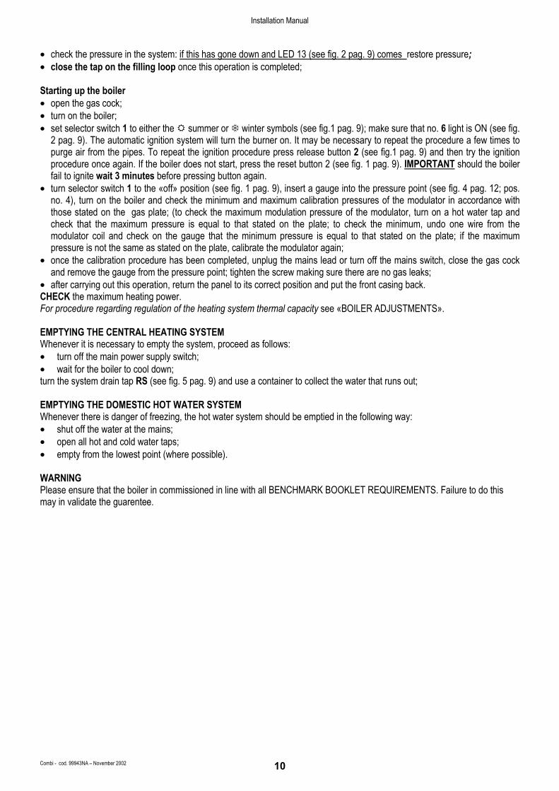
• check the pressure in the system: if this has gone down and LED 13 (see fig. 2 pag. 9) comes restore pressure; • close the tap on the filling loop once this operation is completed; Starting up the boiler • open the gas cock; • turn on the boiler; • set selector switch 1 to either the summer or winter symbols (see fig.1 pag. 9); make sure that no. 6 light is ON (see fig.
2 pag. 9). The automatic ignition system will turn the burner on. It may be necessary to repeat the procedure a few times to purge air from the pipes. To repeat the ignition procedure press release button 2 (see fig.1 pag. 9) and then try the ignition procedure once again. If the boiler does not start, press the reset button 2 (see fig. 1 pag. 9). IMPORTANT should the boiler fail to ignite wait 3 minutes before pressing button again.
• turn selector switch 1 to the «off» position (see fig. 1 pag. 9), insert a gauge into the pressure point (see fig. 4 pag. 12; pos. no. 4), turn on the boiler and check the minimum and maximum calibration pressures of the modulator in accordance with those stated on the gas plate; (to check the maximum modulation pressure of the modulator, turn on a hot water tap and check that the maximum pressure is equal to that stated on the plate; to check the minimum, undo one wire from the modulator coil and check on the gauge that the minimum pressure is equal to that stated on the plate; if the maximum pressure is not the same as stated on the plate, calibrate the modulator again;
• once the calibration procedure has been completed, unplug the mains lead or turn off the mains switch, close the gas cock and remove the gauge from the pressure point; tighten the screw making sure there are no gas leaks;
• after carrying out this operation, return the panel to its correct position and put the front casing back. CHECK the maximum heating power. For procedure regarding regulation of the heating system thermal capacity see «BOILER ADJUSTMENTS». EMPTYING THE CENTRAL HEATING SYSTEM Whenever it is necessary to empty the system, proceed as follows: • turn off the main power supply switch; • wait for the boiler to cool down; turn the system drain tap RS (see fig. 5 pag. 9) and use a container to collect the water that runs out; EMPTYING THE DOMESTIC HOT WATER SYSTEM Whenever there is danger of freezing, the hot water system should be emptied in the following way: • shut off the water at the mains; • open all hot and cold water taps; • empty from the lowest point (where possible). WARNING Please ensure that the boiler in commissioned in line with all BENCHMARK BOOKLET REQUIREMENTS. Failure to do this may in validate the guarentee.
Installation Manual
Combi - cod. 99943NA – November 2002 11
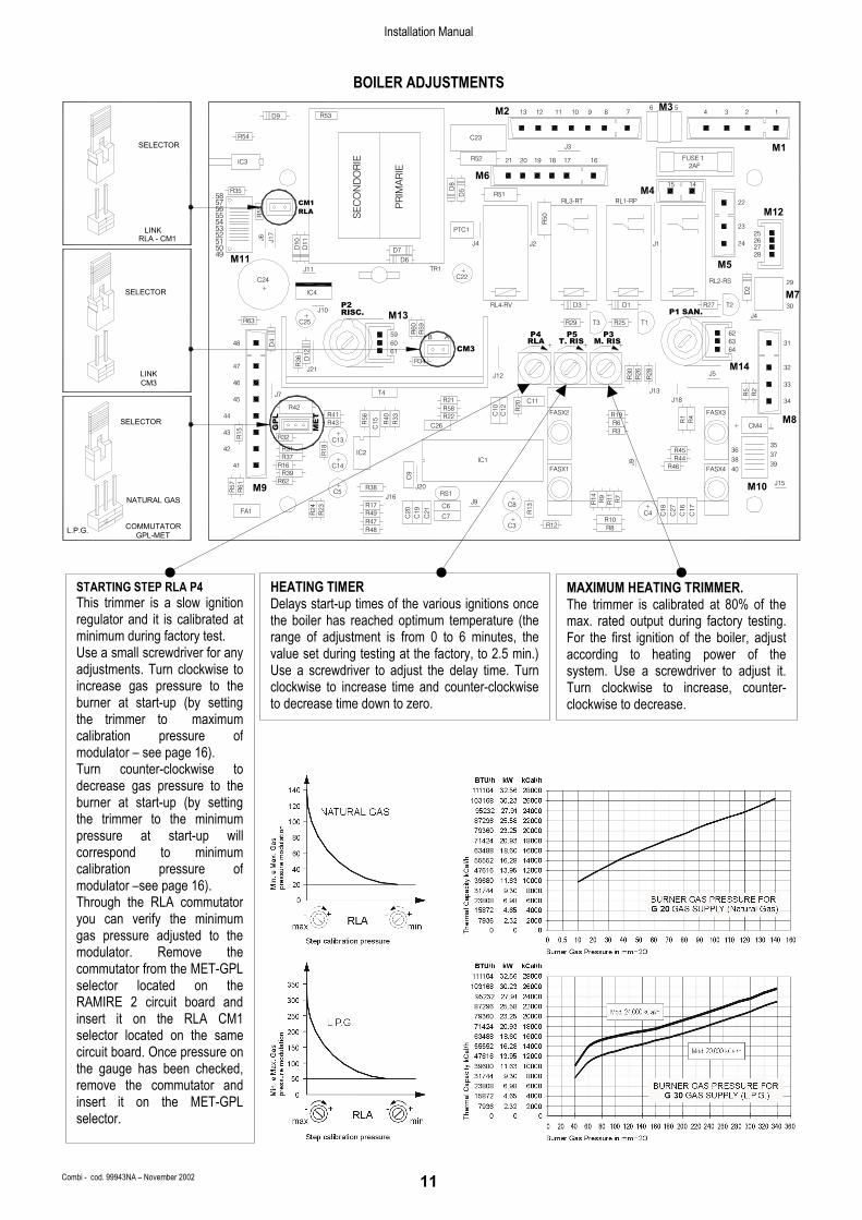
BOILER ADJUSTMENTS
SELECTOR
GPL-MET
NATURAL GAS
L.P.G.
SELECTOR
M5M11 D6
+C22
CM3
RS1J16
R48
R23
R24FA1
C20
C19
C7
C6
C21
R47
R17R49
R15
R32 C13
41 R16 C14
R57
R61
R39R62
M9 J20
C9
C5+ R38
42 R31R37 R
18 IC2+
R58R42
ME
T
43
44
GP
L R41
C26+
R43 R40
C15R
56
R33 R22
45
46
J7 T4R21
M13R63 C25
61
D12
47 J21
R36 R34
48 D4
R59
R60
59 AB60
+IC4
J10+ RISC.
P2
J11
C24
TR1
R14 R9
R11 R7+
R12 R8C3R
13C8J9
+
C17
R10
C18C4
+
C27
C16
R30
R28
R26J12
M10
40FASX4FASX1 R46IC1
36R45
J9 38R4439
J15
3537
R5
C12
C10 R
20
FASX2 FASX3R19
+R3R6 R
1R
4
C11
J13J18
CM4M8
R2
34
33
J4T3R29 R25 T1
M14
64+ + +
J5
P3M. RIS
P4 P5T. RISRLA
6263
32
31
D2
D3RL4-RV T2R27D1P1 SAN.
RL2-RS
M730
29
D5
PTC1
57 CM1 PR
IMA
RIE
SE
CO
ND
OR
IE
5253
51
4950
J17
J6
D11
D10
D7
5556
R55 RLA
54
58R35 D
8
IC3
R53D9
R54
M1
22RL3-RT RL1-RP
J2J4 24J1
R50
232526
2827
M12
M6R51 M4
1415
161819 17
J3
R52 21 20 FUSE 12AF
23412 11 910 8 7M2 13
C23
6 5M31
SELECTOR
RLA - CM1LINK
COMMUTATOR
CM3LINK
STARTING STEP RLA P4 This trimmer is a slow ignition regulator and it is calibrated at minimum during factory test. Use a small screwdriver for any adjustments. Turn clockwise to increase gas pressure to the burner at start-up (by setting the trimmer to maximum calibration pressure of modulator – see page 16). Turn counter-clockwise to decrease gas pressure to the burner at start-up (by setting the trimmer to the minimum pressure at start-up will correspond to minimum calibration pressure of modulator –see page 16). Through the RLA commutator you can verify the minimum gas pressure adjusted to the modulator. Remove the commutator from the MET-GPL selector located on the RAMIRE 2 circuit board and insert it on the RLA CM1 selector located on the same circuit board. Once pressure on the gauge has been checked, remove the commutator and insert it on the MET-GPL selector.
HEATING TIMER Delays start-up times of the various ignitions oncethe boiler has reached optimum temperature (therange of adjustment is from 0 to 6 minutes, thevalue set during testing at the factory, to 2.5 min.)Use a screwdriver to adjust the delay time. Turnclockwise to increase time and counter-clockwiseto decrease time down to zero.
MAXIMUM HEATING TRIMMER. The trimmer is calibrated at 80% of themax. rated output during factory testing.For the first ignition of the boiler, adjustaccording to heating power of thesystem. Use a screwdriver to adjust it.Turn clockwise to increase, counter-clockwise to decrease.

Installation Manual
Combi - cod. 99943NA – November 2002 12
GAS TYPE CONVERSION Conversion of the boiler from natural gas to LPG and vice versa must be performed by qualified personnel only. Conversion is performed as follows: a) turn off the main power
switch; b) close the gas cock; c) substitute the jets on
the main burner as follows:
• undo the gas pipe 5 (fig.1) from the burner manifold using a size 24 spanner;
• separate the burner manifold 2 from the burner ramps 1 by undoing the 4 screws 3 using a Philips screwdriver;
• fit new jets 4 to the burner suitable for the type of gas the boiler will run on using a no. 7 spanner. The jets must be fitted with new gaskets;
• reassemble the entire burner unit. Use the soapy water method to check for gas leaks each time gas connections are dismantled and reassembled;
d) change the spring 6 (fig.2) to suit the type of gas used. The spring is located inside the stabiliser in the gas valve 8. To change the spring, open the fastening clips 2 and, after unhooking the coil 1, remove the modulator core 7 and change the spring; once this has been done reassemble everything; e) move the jumper on the circuit board to suit the type of gas (fig.4). f) replace the gas setting plate that indicates the type of gas and nominal pressure for the boiler. When converting the boiler to work with a different type of gas, remove the existing plate and replace it with the new one supplied in the conversion kit. g) calibrate the new max. and min. settings for the modulator.
DATA TABLE
Models: RSF 20 E NATURAL GAS G 20 LIQUID BUTAN GAS G 30 LIQUID PROPANE GAS G 31 Lower Wobbe index (15°C; 1013 mbar) MJ/m3n 45.67 80.58 70.69 Rated feed pressure mbar(mm c.w.) 20(204) 30(306) 37(377) Minimum feed pressure mbar(mm c.w.) 17(173.4) 20(204) 25(255) Main burner: 13 jets - Ø jet mm. 1.25 0.75 0.75 Consuption (15°C; 1013 mbar) mc/h. 2.8 Consuption (15°C; 1013 mbar) Kg/h. 2.10 2.07
Models: RSF 24 E NATURAL GAS G 20 LIQUID BUTAN GAS G 30 LIQUID PROPANE GAS G 31 Lower Wobbe index (15°C; 1013 mbar) MJ/m3n 45.67 80.58 70.69 Rated feed pressure mbar(mm c.w.) 20(204) 30(306) 37(377) Minimum feed pressure mbar(mm c.w.) 17(173.4) 20(204) 25(255) Main burner: 13 jets - Ø jet mm. 1.25 0.77 0.77 Consuption (15°C; 1013 mbar) mc/h. 3.15 Consuption (15°C; 1013 mbar) Kg/h. 2.35 2.32
12
34
5
11
10
8
7
69
43
1
1110
2
5
5
13
12
4
7
5
86
123
LEGEND: 1. Gas valve mod. VK4105A 2. Pressure modulator 3. Inlet pressure point 4. Outlet pressure point 5. Electronic ignition board 6. Gas pipe 7. Burner manifold 8. 13 ramp gas burner 9. Injectors 10. Ignition electrodes 11. Flame ionisation electrodes 12. Ignition board fastening screws 13. Ignition board cover
LEGEND: 1. Modulating coil 2. Fastening clips 3. Min. gas pressure adjustament srew 4. Max. gas pressure adjustament core 5. Core lock nut 6. Calibrator spring (blue natural gas) (grey L.P.G.) 7. Pressure modulator 8. Gas valve stabiliser
GAS BURNER UNIT PRESSURE MODULATOR Link Jumper on RAMIRE ciruit board
Fig. 1 Fig. 2 Fig. 3
Fig. 4
Fig. 5

Installation Manual
Combi - cod. 99943NA – November 2002 13
REGULATING THE GAS PRESSURE Maximum and minimum modulation pressures. N.B. The following operations must only be carried out by authorised personnel and are necessary when the boiler is converted to run on one type of gas or another or also in cases where the maximum pressure is not the same as that shown on the plate. Calibration pressure.
Boiler Power Rating Natural Gas L.P.G.
Min. Max. Min. Max.
20.000 kcal/h mmbar 2 11 5 29
24.000 kcal/h mmbar 4.2 13 5 31
KEY: (see fig. A) 1) Modulating coil 2) Fastening clips 3) Min. gas pressure adjustment screw 4) Max gas pressure adjustment core 5) Core lock nut 6) Calibrator spring 7) Modulator core 8) Gas valve stabiliser Fig. B) Widen locking clips (2); Fig. C) Slide out the coil (1) located above the gas valve; Fig. D) Tighten plastic screw (3) by turning it clockwise, be careful not to break it. Fig. E) Use a no.17 spanner to undo the lock nut (5) which holds the core (4) of the coil in place; undo the screw and insert a pressure gauge; Fig. F) Turn on the boiler, regulate the maximum pressure by turning the core (4) (clockwise to increase pressure, counter clockwise to decrease). Once maximum pressure has been set, tighten the lock nut (5); Fig. G) Adjust minimum modulation pressure with the coil disengaged: slowly unscrew plastic screw (3) until the pressure gauge shows the minimum pressure required. Fig. H) Once these operations are completed, seal the plastic screw with paint or enamel; reassemble the coil (1) by pressing it back into place; remove the gauge, tighten the screw and use a soapy solution to check for any eventual l leaks.
109
1
1
4
54
3
1
54
2
7
4
86
4
1
54 23 1
Fig. A
Fig. B
Fig. C
Fig. D
Fig. E
Fig. F
Fig. G
Fig. H

Installation Manual
Combi - cod. 99943NA – November 2002 14
TECHNICAL DATA
DIFFERENTIAL AIR PRESSURE SWITCH FOR FAN CONTROL To guarantee maximum safety in flue exhaust, a differential pressure switch is installed on the Room Sealed Combustion Chamber Model (wall-mounted, room-sealed boilers) and on forced draught boilers. This pressure switch automatically controls perfect functioning of the fan and the passage of both external air and exhaust flue pipes.
DIVERTER VALVE VC 6012MG6000 The diverter valve is the device which controls the boiler switching from central heating to d.h. water circuit and vice versa. The diverter valve is fitted with a manual command lever L (see fig. 2) which, when set on the top position, towards the valve head, allows the boiler operating on the domestic hot water circuit while, when set on the low position, the boiler operates on the central heating circuit. When the L lever is set on the central position, it allows the actuator on midway. In this position, to be used only in case of motor failure or damage, both central heating and domestic hot water ports are open and both domestic hot water and central heating circuits are operating. For restore the initial position, separate the actuator and the valve body following instructions from no.1 to no.4 (see fig.1). To separate the motor from the valve body proceed as follows: 1. Press button A under the motor. 2. Simultaneously keep the A button pressed and turn the actuator counter-
clockwise; 3. Lift off the motor 4. To disconnect the power supply cable press the B tap located on the pin C. See fig.4 to perform the electrical wiring of the diverter valve to the main printed circuit board.
LIMITER The boiler is equipped with a variable flow limiter at the cold water inlet. The flow limiter can be adjusted by turning the screw (see fig.2 pos.C) in order to obtain the correct flow rate of domestic hot water for the specific boiler output.
FLOWSWITCH This device gives precedence to domestic hot water and is fitted to boilers which supply instantaneous hot water. It allows conversion to hot water even with a minimum hot water demand (min. 2 litres), using an electromagnetic (see fig. 5) principle with electrical switching by means of a relay. The device is made of non-toxic, corrosion-proof ZYTEL 101 L plastic material which has type approval with non-toxic characteristics and is unaffected by hard water. In addition, a filter is fitted before the flowswitch and at the cold water inlet which eliminates any water impurities. These features guarantee that the flowswitch operation is highly efficient.
VALVED.H.W. EXCHANGER
D.H.W. EXCHANGER
FLOWSWITCH
Fig. 1
Fig. 4
Fig. 3
Fig. 2 Fig. 1
Fig. 5

Installation Manual
Combi - cod. 99943NA – November 2002 15
BY-PASS
All boilers are fitted with a by-pass. This element is essential in the following cases: • if a two-way zone valve is installed • if thermostat valves are installed in the radiators. To adjust the by-pass proceed as follows (see fig.1 pos.A): fit the screwdriver to the plastic screw of the by-pass, bearing in mind that when the slot of the screw is horizontal the by-pass is totally open, allowing all the water to pass, while when it is vertical the by-pass is totally closed. For partial by-pass flows, use the adjuster screw. MAIN COMPONENTS mod. RSF 20 E - RSF 24 E
KEY 1. FRAME 2. FLUE HOOD – ROOM SEALED COMBUSTION CHAMBER 3. COMBUSTION CHAMBER 4. ROOM SEALED CHAMBER COVER 5. ROOM SEALED CHAMBER BACK 6. HEAT EXCHANGER Mod. 20.000
HEAT EXCHANGER Mod. 24.000 7. D.H.W. EXCHANGER H20-H20 PB 21-73
D.H.W. EXCHANGER H20-H20 PB 24-73 8. EXCHANGER AIR VENT VALVE 9. MULTIGAS BURNER WITH 13 RAMPS 10. IGNITION ELECTRODE 11. FLAME IONISATION ELECTRODE 12. HEATING SAFETY THERMOSTAT 13. ELECTRONIC GAS VALVE VK4105 A 1001 14. GAS PRESSURE MODULATOR 15. ELECTRONIC IGNITION BOARD 16. EXPANSION VESSEL 17. 3-SPEED CIRCULATION PUMP WITH AIR VENT 18. AUTOMATIC AIR VENT 19. HEATING CIRCUIT 3 bar PRESSURE RELIEF VALVE 20. DRAINING TAP 21. WATER PRESSURE GAUGE 22. WATER PRESSURE SWITCH 23. HEATING SENSOR 24. HOT WATER SENSOR 25. 3-WAY DIVERTER VALVE 26. FLOWSWITCH CONNECTION WITH FLOW LIMITER 27. ELECTRONIC FLOWSWITCH 28. BY-PASS 29. AIR PRESSURE SWITCH 30. FAN
20
1319 23 14 15 24 26
20
18
17
5
911
3
6
2
29
304
8
2725
287
12
24
16
1
A
B
CFig. 1
Fig. 2

Installation Manual
Combi - cod. 99943NA – November 2002 16
ELECTRICAL CONNECTION FOR
ROOM SEALED COMB. CHAMBER ELECTRONIC IGNITION BOILER – mod. RSF 20 E - RSF 24 E
M4M1 M5 M6
m1
RL1
GAS VALVEPRESSURE
MODULATOR
42 414446 454748 43M10
blue
brow
n
blac
k
blac
k
blac
k
M.F.
M9
WATER
SWITCHback
blue
brow
n
FA1
PRESSURE
3 C 2
CONTROLREMOTE
-IN+ REMOTE SENSOR
TEL
00.0
SE
XT
2 1M1
00.0
OR TAOUT-DOOR
21
3
m3
IGNITION
OPTIONAL
P.C.B.N
12111097 8 LB13L
LPS INTERFACE
N REMOTE
blac
k
blue
lght
-blu
e
brown
brow
n
TERMINAL BLOCK TS
512 67891011 4
ELECTRONIC IGNITION S4565A20ELECTRODE
NL
ATTENTION:
light
-blu
e
light
-blu
e
REDCX
FILTRO NET FILTERCYCY
PUMP
P
IGR br
own
brow
n
M8
oran
ge
oran
ge
m2
V 5+ 4-Z
brown
blac
k
blac
k
red/black
brown8 7 28272625
10000 - 25°C
blackE.I
blackblack SENSOR
D.H. WATER
DIVERTORAIR PRESS.SWITCH
FAN
black
31 3332 34
black
SENSORHEATING
VALVE
10000 - 25°C
C B
6 light
-blu
e
light
-blu
e
54 3 WAY
A
brow
n
blac
k
blac
k
brow
n
RLA
D448 60
B A M. RIST. RIS 63 31
RAVI 2 CIRCUIT BOARD-ELECTRONIC TEMPERATURE INDICATOR WITH SELF-DIAGNOSTIC
WIRING OF COMPONENTS BY MEANS OF CONNECTORS
23
LED5
C6
C7
RS1
R58R22
R21
421 3 15 14 22
LED2LED1 LED3 LED4
RAVI II
R3142
R18
R17yellow blue
R48
FA1C
20R49R23
R24
R47C
19
C21
red brownR39
C9
M9R62
R61
R57
J16R38+
C5J20
R3741 R16 C14
IC2+
J7 T4
1235 4
GP
L
C15 R
40
R56
MET R43 R
33
R15
R3243
C13+
C26
R4244
45
R41
47 J21
R36
46
D12 61
R34
24 1716 18 19 2120
LED8LED6 LED7 LED9 LED10 LED11
J2 M1D2 8 7 6 5
J3
34 2 1
3536
+C8J9
C3 R12
R13
+
4038IC1
M10 J15
3937
J13 R5
R2
R20
C12
C10
J18
M8CM4+
34
64
M14J12 R
28
R30
R26 J5
CM3 + + +
32
33
RAMIRE 3 CIRCUIT BOARD STANDARD ON ALL MODELS
D8
N.B. M1 CONNECTOR OF THE RAVI 2
5253
Wiring diagram +
M13J10 RISC.+
C25R63
R60
59 R59
IC4
P2
TIME CLOCKM11 D6
49
J11
C24
TR1
D11J1
7
5051 J6
D10
D7
CIRCUIT BOARD MUST BE CONNECTED TOTHE M11 CONNECTOR OF THE RAMIRE 3CIRCUIT BOARD.
SE
CO
ND
AR
IO
PR
IMA
RIO
57 CM1RLA
5554
R5556
R3558
IC3
R54
D9 R53
PTC1 25
29
62
P1 SAN.
P4
R29
P5
T1R25T3
P3
RL4-RV D3 D1 T2R27
J4
D2
M730
C22+
M5
RL2-RS
J2J4 J1
282724 26
M6
RL1-RPRL3-RT
R50
R51D5 M4
1415
22
M1223
J3
1621 20R52 1718192AF
FUSE 1
C23
M1
9M2 13 101112 8 7 346 M3 5
2 1
N.B.: IN CASE OF REMOTE CONTROL INSTALLATION, FORCORRECT OPERATION, REMOVE LINK BETWEEN TERMINALS TA-OR ON TERMINAL BLOCK, AND SET SUMMER-WINTER SWITCH OFCONTROL PANEL ON SUMMER POSITION. CHECK THE POSITION OF M10 BEFORE INSERTING IT.

Installation Manual
Combi - cod. 99943NA – November 2002 17
WIRING DIAGRAM FOR ROOM SEALED COMB. CHAMBER ELECTRONIC IGNITION BOILER – mod. RSF 20 E - RSF 24 E
11
OR
RVA-RVBRTA
- IONISATION ELECTRODE- IGNITION ELECTRODE
RSARPART
- LOCK-OUT INDICATOR- RESET BOTTON
- THERMOSTAT RELAY
RPRV
RS
EA
- PUMP RELAY- D.H. WATER RELAY
PAV
- FAN RELAY
ER
- ROOM THERMOSTAT- MODULATING UNIT
LB
- TIME CLOCKPS
- MAIN SWITCH
- SUMMER-WINTER SWITCH
- SAFETY THERMOSTAT
MDTA
E.I.
- HEATING SENSOR
TSM.F.
- PUMPP
- LINE
*
- WATER PRESSURE SWITCH- NEUTRAL
SRSS
VD
KEY
IG
SRLN E.I
MD
34 31 47 483233 42 252741
46
RT
S45
65A
20
19PS
5
4
8
LB
6
7TS
9
10
9
10
PUMP CONTROL ANDPRIORITY BLOCK
52
MET
/GPL
45
1.5 barFA1
RS
RP
431 bar
PAC 44
RLA
TIMER RIS.
RSA RTAT. SAN
RLAT. RIS
50
49
51
MAX. RIS
60°
53
55
54
RVB
40°
30°57
56
50°58
RV
80°
70°
17 2319 2418 22
12
13
12
11
EA
8
ER
6
RPAP
15
PTC2 14
5
20
21V
RVA 16
2 137 4
PA
*
VDNET FILTER
IG
R
CY CY
CX
NL
- AIR PRESSURE SWITCH- FAN
- PUMP RELAY CONTACT- D.H. WATER RELAY CONTACT- FAN RELAY CONTACT- THERMOSTAT RELAY CONTACT
- FLOWSWITCH MICRO-SWITCH
- 3 WAY DIVERTOR VALVE- WIRING CONNECTION ONLY FOR Mod. VC6012
- D.H. WATER SENSOR
SSM.F.
RL1
28
78
2630 29
Z 4-5+V
-IN+
SEXT
TEL
M1 12
TAOR
RAMIRE 3 SM20012
RAVI2SK06205
brow
n
light
-blu
e
blac
k
black
brown
blu
black
blac
k
blac
k
blac
k
blac
k
brow
n
blu
oran
ge
oran
ge
blac
k
blac
k
blac
k
brow
n
brow
n
red/
blac
k
OUT-DOORREMOTE SENSOR
CONTROLREMOTE
black
brown
blue
black
light-blue
brown
blac
k
blac
k
light
-blu
e
brow
n
light
-blu
e
brow
n
blac
k
light-blue
brown
PA
N.B.: IN CASE OF REMOTE CONTROL INSTALLATION, FORCORRECT OPERATION, REMOVE LINK BETWEEN TERMINALS TA-OR ON TERMINAL BLOCK, AND SET SUMMER-WINTER SWITCH OFCONTROL PANEL ON SUMMER POSITION. CHECK THE POSITION OF M10 BEFORE INSERTING IT.
ELEC
TRO
NIC
TEM
PERA
TURE
IND
ICAT
OR
THER
MO
STA
TS A
ND
MO
DU
LATI
ON
BLO
CK
Installation Manual
Combi - cod. 99943NA – November 2002 18
MAINTENANCE
To keep the boiler in efficient and safe operating condition, we recommend you perform the following checks at least once a year: • Check all seals on the gas side and replace gaskets to
restore perfect seal as required. • Check all seals on the water side and replace gaskets to
restore perfect seal as required. • Visually check combustion and the combustion chamber;
dismantle and clean the chamber if necessary. • Check the primary exchanger and clean it if necessary. • Check functioning of gas safety systems: Insufficient gas
safety device (flame detection sensor for electronic ignition boilers) thermocouple for pilot light boilers.
• Check functioning of heating safety systems: safety thermostat for temperature limit, safety sensor for pressure limit.
• Check the exhaust flue safety device • Check the max. and min. modulation pressures and the
modulation. • Check that the electrical connection conforms to the
description in the instruction manual for the boiler. • Check the domestic hot water flow rate and
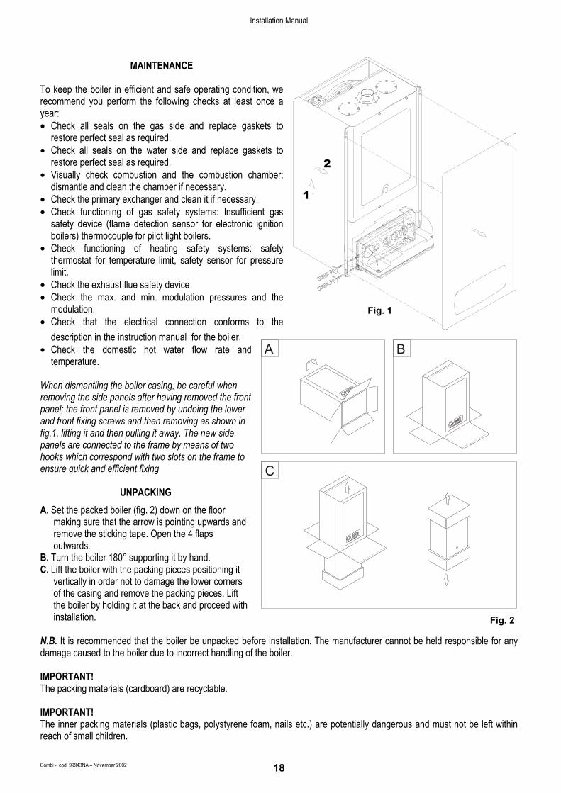
temperature. When dismantling the boiler casing, be careful when removing the side panels after having removed the front panel; the front panel is removed by undoing the lower and front fixing screws and then removing as shown in fig.1, lifting it and then pulling it away. The new side panels are connected to the frame by means of two hooks which correspond with two slots on the frame to ensure quick and efficient fixing
UNPACKING A. Set the packed boiler (fig. 2) down on the floor
making sure that the arrow is pointing upwards and remove the sticking tape. Open the 4 flaps outwards.
B. Turn the boiler 180° supporting it by hand. C. Lift the boiler with the packing pieces positioning it
vertically in order not to damage the lower corners of the casing and remove the packing pieces. Lift the boiler by holding it at the back and proceed with installation.
N.B. It is recommended that the boiler be unpacked before installation. The manufacturer cannot be held responsible for any damage caused to the boiler due to incorrect handling of the boiler. IMPORTANT! The packing materials (cardboard) are recyclable. IMPORTANT! The inner packing materials (plastic bags, polystyrene foam, nails etc.) are potentially dangerous and must not be left within reach of small children.
2
1
Fig. 2
A B
C
Fig. 1
Installation Manual
Combi - cod. 99943NA – November 2002 19
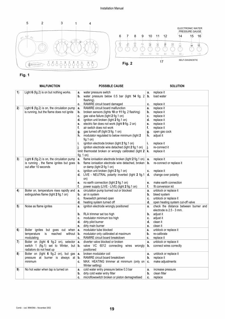
MALFUNCTION POSSIBLE CAUSE SOLUTION
1) Light 6 (fig.2) is on but nothing works. a. water pressure switch b. water pressure below 0.5 bar (light 14 fig. 2
flashing). c. RAMIRE circuit board damaged
a. replace it b. load water c. replace it
2) Light 6 (fig.2) is on, the circulation pump is running, but the flame does not ignite
a. RAMIRE circuit board malfunction b. broken sensors (lights 10 or 11 fig. 2 flashing) c. gas valve failure (light 2 fig.1 on) d. ignition unit broken (light 2 fig.1 on) e. electric fan does not work (light 9 fig. 2 on) f. air switch does not work g. gas turned off (light 3 fig. 1 on) h. modulator regulated to below minimum (light 2
fig.1 on) i. ignition electrode broken (light 2 fig.1 on) j. ignition electrode wire detached (light 2 fig.1 on) limit thermostat broken or wrongly calibrated (light 2 fig. 1 on)
a. replace it b. replace it c. replace it d. replace it e. replace it f. replace it g. open gas cock h. adjust it i. replace it j. re-connect it k. replace it
3) Light 6 (fig.2) is on, the circulation pump is running , the flame ignites but goes out after 10 seconds
a. flame ionisation electrode broken (light 2 fig.1 on) b. flame ionisation electrode wire detached, broken
or damp (light 2 fig.1 on) c. ignition unit broken (light 2 fig.1 on) d. LIVE - NEUTRAL polarity inverted (light 2 fig.1
on) e. no earth connection (light 2 fig.1 on) f. power supply (LIVE - LIVE) (light 2 fig.1 on)
a. replace it b. re-connect or replace it c. replace it d. change over polarity e. make earth connection f. fit conversion kit
4) Boiler on, temperature rises rapidly and extinguishes flame (light 2 fig.1 on)
a. circulation pump burned out or blocked b. air in system c. flowswitch jammed open d. heating system turned off
a. unblock or replace it b. bleed system c. unblock or replace it d. open heating system cut-off valve
5) Noise as flame ignites a. ignition electrode wrongly positioned b. RLA trimmer set too high c. modulator minimum too high d. dirty pilot burner e. dirty main burner
a. check the distance between burner and electrode is 2.5 - 3 mm.
b. adjust it c. adjust it d. clean it e. clean it
6) Boiler ignites but goes out when temperature is reached without modulating
a. modulator tube blocked b. modulator only calibrated at maximum c. RAMIRE circuit board breakdown
a. unblock or replace it b. re-calibrate c. replace it
7) Boiler on (light 6 fig.2 on), selector switch 1 (fig.1) set to Winter, but radiators do not heat up
a. diverter valve blocked or broken b. valve VC 6012 connecting wires wrongly
positioned
a. unblock or replace it b. connect wires correctly
8) Boiler on (light 6 fig.2 on), but gas pressure at burner is always at minimum
a. broken modulator coil b. RAMIRE circuit board breakdown c. MAX. HEATING trimmer at minimum (only on
Winter setting)
a. unblock or replace it b. replace it c. make adjustments
9) No hot water when tap is turned on a. cold water entry pressure below 0.3 bar b. dirty cold water entry filter c. microflowswitch broken or piston demagnetised
a. increase pressure b. clean filter c. replace
45 2 3 1ELECTRONIC WATERPRESSURE GAUGE
SELF-DIAGNOSTIC17
6 7 8 12109 11 14 1615
Fig. 1
Fig. 2
Installation Manual
Combi - cod. 99943NA – November 2002 20
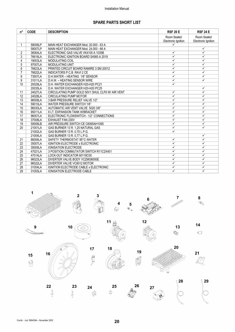
SPARE PARTS SHORT LIST
n° CODE DESCRIPTION RSF 20 E RSF 24 E
Room Sealed
Electronic Ignition Room Sealed
Electronic Ignition 1 58006LP MAIN HEAT EXCHANGER Mod. 20.000 - 63 A 58007LP MAIN HEAT EXCHANGER Mod. 24.000 - 66 A 2 36064LA ELECTRONIC GAS VALVE VK4105 A 1035B 3 76616LA ELECTRONIC IGNITION BOARD S4565 A 2019 4 18003LA MODULATING COIL 5 97007LA MODULATING UNIT 6 76623LA PRINTED CIRCUIT BOARD RAMIRE 3 SM 20012 7 76622LA INDICATORS P.C.B. RAVI 2 CE 8 73507LA D.H.WATER – HEATING 1/8” SENSOR 9 31011LA D.H.W. – HEATING SENSOR WIRE 10 20029LA D.H. WATER EXCHANGER H20-H20 PC21 20035LA D.H. WATER EXCHANGER H20-H20 PC25
11 24027LA CIRCULATING PUMP GOLD 50V1 SHUL CLF6 W/ AIR VENT 12 24028LA CIRCULATING PUMP MOTOR 13 96008LA 3 BAR PRESSURE RELIEF VALVE 1/2’’ 14 59010LA WATER PRESSURE SWITCH 1/8’’ 15 96030LA AUTOMATIC AIR VENT VALVE 5020 3/8’’ 16 95011LA 8 LT. EXPANSION TANK W/BRACKET 17 96007LA ELECTRONIC FLOWSWITCH - 1/2’’ CONNECTIONS 18 37008LA EXHAUST FAN 230V 19 59006LB AIR PRESSURE SWITCH CE C6065AH1095 20 21001LA GAS BURNER 13 R. 1,25 NATURAL GAS 21002LA GAS BURNER 13 R. 0,75 L.P.G. 21004LA GAS BURNER 13 R. 0,77 L.P.G.
21 86006LA SAFETY THERMOSTAT 95°C WATER 22 35007LA IGNITION ELECTRODE x ELECTRONIC 23 35009LA IONISATION ELECTRODE 24 47021LA 3 POSITION COMMUTATOR SWITCH R11C2X401 25 47014LA LOCK-OUT INDICATOR 60118C00 26 96023LA DIVERTER VALVE BODY VCZMG6000E 27 96022LA DIVERTER VALVE VC6012 MOTOR 28 31054LA IGNITION ELECTRODE CABLE x ELECTRONIC 29 31055LA IONISATION ELECTRODE CABLE
19
22
16
2423 25
1817
9
1
11 12
2 3
B AB
A
26
H
27
2021
2928
13 14
4 56
15
7 8
10

RADIANT BRUCIATORI S.p.A.
Registered Office: 61025 Montelabbate (PU) Italy • Via Pantanelli, 164
Phone +39 0721 90791 15 linee telefax. +39 0721 9079299 (italy) - +39 0721 9079279 (export) Email: [email protected] • [email protected] • [email protected]
Internet: http://www.radiant.it
UK – Radiant Helpline – 01329.828555
All descriptions and illustrations contained in this leaflet have been carefully prepared but we reserve the right to make changes and improvements in our products whitch may affect the accurancy of the information contained in this leaflet. E + OE All rights reserved. No part of this document may be reproduced, saved in storage systems or transmitted in any form or by any means, whether electronic, mechanical, photocopying, recording or others, without the Manufacturer's prior authorisation in writing.
Cod
e 99
943N
A •
Sept
embe
r 200
2