RADIALcvt as an electric vehicle transmission - Varibox · RADIALcvt as an electric vehicle...
12
1 | Page RADIALcvtElectricVer1.4.docx RADIALcvt as an electric vehicle transmission Dr. J. J. Naude 19 July 2017 Version 1.4
Transcript of RADIALcvt as an electric vehicle transmission - Varibox · RADIALcvt as an electric vehicle...

1 | Page RADIALcvtElectricVer1.4.docx
RADIALcvt as an electric
vehicle transmission
Dr. J. J. Naude 19 July 2017
Version 1.4

2 | Page RADIALcvtElectricVer1.4.docx
Table of contents
1 Current status of electric vehicle transmissions 3
2 Conclusions 6
2.1 Single speed 6
2.2 Multiple stepped speed 6
2.3 Variable mechanical drives 7
2.4 RADIALcvt as an ideal electric vehicle CVT transmission 7
3 References 9
List of Figures
Figure 1 Electric motor speed vs motor power efficiency (David, 2011) .................................. 3
Figure 2 Electric motor speed vs motor power efficiency (Turner, Cavallino, & Viotto, 2011) 4
Figure 3 (Bottiglione, De Pinto, Mantriota, & Sorniotti, 2014) ................................................. 5
3 | Page RADIALcvtElectricVer1.4.docx
1 Current status of electric vehicle transmissions
With the current drive towards electric vehicles, optimization of the various components
contributing to the overall energy efficiency of the electric vehicle is becoming more
important. As development to higher energy dense batteries and other energy storing
devices continues it is a very high priority not to have inefficient components deteriorates
any advances in this development. The norm for current electric vehicles is not merely a
means to get from point a to b but includes super cars like Tesla and Nio and normal
passenger vehicles which all demand, all the features as included in equivalent internal
combustion vehicles. The pure electric vehicle is here to stay and will increase its stepped
ratios to 3 and 4 and its market share will grow and development will continue as reported
by ZF (Tom, 2014) and Bosch (Beissmann, 2014).
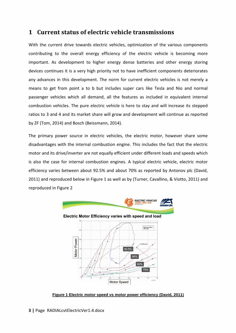
The primary power source in electric vehicles, the electric motor, however share some
disadvantages with the internal combustion engine. This includes the fact that the electric
motor and its drive/inverter are not equally efficient under different loads and speeds which
is also the case for internal combustion engines. A typical electric vehicle, electric motor
efficiency varies between about 92.5% and about 70% as reported by Antonov plc (David,
2011) and reproduced below in Figure 1 as well as by (Turner, Cavallino, & Viotto, 2011) and
reproduced in Figure 2
Figure 1 Electric motor speed vs motor power efficiency (David, 2011)

4 | Page RADIALcvtElectricVer1.4.docx
Figure 2 Electric motor speed vs motor power efficiency (Turner, Cavallino, & Viotto, 2011)
(Turner, Cavallino, & Viotto, 2011) indicated about 10% improvement in energy efficiency
when utilising a 2 speed transmission in combination with the electric motor compared to
the single fixed ratio. The 2 speed implementation added 19 kg of mass to the single speed
transmission. A dry clutch, sprag and locking ring were added in the 2 speed
implementation. Above was based on a 60 to 70 kW front wheel drive minibus
implementation. The exact ratios for the motor to lay shaft reductions are not given in
(Turner, Cavallino, & Viotto, 2011) but from their Figure 2, are estimated as about 3.5:1 for
the first speed and 2.5:1 for the second speed, thus a ratio range of about 3.5/2.5=1.4,
which is very low.
Antonov’s dual clutch 3 speed transmission is presented in (David, 2011) as implemented in
a Jaguar XJ known as the Limo Green (Case Study:Limo Green - eco-friendly Luxury
Limousine), powered by a 170 HP (129kW) electric motor and reporting an energy saving of
up to 14.7%.
Antonov also integrated their dual clutch 3 speed transmission into a 3.5 ton Smith Electric
Vehicle, demonstrator known as “E-Van”.

5 | Page RADIALcvtElectricVer1.4.docx
Typical ratios from (David, 2011) indicate that the 3 speed transmission has ratios of about
3.8:1, 2.3:1 and 1.7:1, thus with a ratio range of 3.85/1.7=2.3 which is also relatively low.
More recent publications on multi speed electric vehicles, which include mechanical variable
speed transmissions (CVT), include (Wang, Liu, Liu, & Xu, 2016) and (Bottiglione, De Pinto,
Mantriota, & Sorniotti, 2014).
Figure 3 (Bottiglione, De Pinto, Mantriota, & Sorniotti, 2014)
The work of (Bottiglione, De Pinto, Mantriota, & Sorniotti, 2014) based on a 28kW, 108 N.m
electric motor (motor efficiency presented in Figure 3) in a 872 kg vehicle compared
transmissions that include, single and two speed, full and half toroidal, as well as two IVT
(infinitely variable transmissions). The result show that at constant speed and load the
single and two speed transmissions outperform (lower energy consumption) the variable
ratio ones, as can be expected due to the lower mechanical efficiency of the latter. However
in the UDC and the J10-15 drive cycle (city driving) the half toroidal outperformed the fixed
ratios by 10% and 15% respectively. The advantage is gain by the variable drive, by being
able to fully optimise the electric motor in drive conditions and well as in regeneration
conditions.
As a very advanced four speed electric vehicle transmission example, Oerlikon Graziano,
discusses their clutch less four-speed EV transmission in (Torrelli, 2012). This transmission
called an e-DCT, presents a DCT but without the dual clutch. The clutch function is

6 | Page RADIALcvtElectricVer1.4.docx
eliminated by using two motors, one coupled directly to the even ratios and the other
directly to the uneven ratios. This transmission offers 15% improvement in vehicle efficiency
and is intended for the high end EV vehicles.
Bosch also forecasts multiple ratios for electric vehicles and continued growth in their
market share and development as reported by (Beissmann, 2014)
2 Conclusions
When considering a transmission for a pure electric vehicle the following can be concluded
for the above mentioned work which convers some electric vehicles in the range of 28kW to
129kW.
2.1 Single speed
A fixed drive (single speed) has the lowest cost and is the least complicated, requiring at
most a locking ring (dog clutch) to tow the vehicle in emergency conditions. This
configuration however have no means to optimise the overall vehicle energy consumption
as far as configuration between electric motor and wheels is concerned, besides the
optimized selection of the fixed gear ratio between motor and wheels.
2.2 Multiple stepped speed
When multiple stepped ratios (two and three speeds and more) are considered, the
following issues arise, and the solutions to these exponentially increase the complexity if
compared to the single speed case:
� All the reviewed work indicates that ratio change synchronisation with a single
electric motor is not possible without a clutch (except the Oerlikon 4 speed high end
EV transmission which requires two motors). As a result all the reviewed multi speed
transmissions functions as an AMT (automated manual transmission) or as a DCT
(dual clutch transmission) as in the case of the Antonov transmission all using a
clutch or dual clutch respectively.
� In order to realise above, a clutch system with automated clutch control is needed
� Also an automated ratio changing mechanism is required.

7 | Page RADIALcvtElectricVer1.4.docx
The upside to a stepped multi speed is that high mechanical efficiency is maintained if
compared to the single speed and that the electric motor is partially optimised in driving
and regeneration conditions to provide energy consumption up to about 15% compared to
the single speed. It also allows for partial optimisation of the electric motor in terms of size,
speed range and torque range.
2.3 Variable mechanical drives
All the reviewed work which considered CVT’s/IVT’s used existing well known systems
limited to toroidal and belt/chain CVT transmissions as well as these transmissions in
IVT/power split configurations. These transmissions are characterised by the following
disadvantages:
� Much lower mechanical efficiency than a fixed ratio.
� All require a hydraulic control system.
� They are heavy and expensive.
� All toroidal and belt/chain CVT include an overdrive in their ratio range (output turns
faster than the input) thus additional reduction gearing would be needed in electric
vehicle implementation.
On the upside these transmissions provide the following advantages:
� Fully optimise the electric motor in driving and regeneration conditions.
� Provide better vehicle acceleration and gradient ability.
� Has the definite potential to provide better energy consumption than stepped
transmission if its mechanical efficiency is within certain limits.
� They do not require a clutch, but only a locking ring/dog clutch, the same as for the
single speed.
2.4 RADIALcvt as an ideal electric vehicle CVT transmission
The RADIALcvt is a new CVT transmission being developed by Varibox. Full details of the
RADIALcvt simulation (Naude, 2017) can be obtained from
http://www.varibox.com/media/1177/radialcvtdesignver16.pdf. The executive summary of
this document is reproduced in Appendix A at the end of this document. It has a number of
fundamental advantages over current commercial and developmental CVT’s and if

8 | Page RADIALcvtElectricVer1.4.docx
considering its use in above cited work (thus as an electric vehicle transmission), thus
considering a power range of 30kW to 130kW with a maximum ratio range of 2.3, the
following can be concluded, while using the same size RADIALcvt unit with a 292mm disk
diameter:
� For a ratio range of 2.3 the RADIALcvt disk radius (RB and RC) will vary from 65 mm to
150mm.
� For the base case of a 30 kW configuration the variator contact efficiency will vary
from about 97.5% to 98.7% as per (Naude, 2017) Figure 12.
� For the case of 130 kW configuration the variator contact efficiency will vary from
about 95.8% to 98.2% as per (Naude, 2017) Figure 16.
� The RADIALcvt does NOT use a hydraulic control system.
� Ratio actuation is done via 12V PWM control of an estimated 150Watt electric
motor.
� The clamping force related bearing losses in the above RADIALcvt is estimated at
about 1.4% to 1.2% as per (Naude, 2017) Figure 12.
� Above is realised while all maximum Hertz contact stresses are below 2 GPa, thus
durability is not an issue.
� The RADIALcvt does not include an overdrive in its ratio range, thus its output can
drive the wheels through the normal reduction to the differential.
� No clutch or clutch control system are required, but only a locking ring/dog clutch
(for emergency towing) as is the case with all the other electric vehicle
transmissions.
Above RADIALcvt mechanical efficiency is at most within an estimate of about 3% less
than the stepped transmissions while it is much more compact lengthwise than the
stepped transmission with a clutch or dual clutch.
The various cited CVT simulations proved the advantages of a CVT transmission in pure
electric vehicles, but the low overall efficiencies of current commercial CVT’s in some
cases eroded all the advantages away.
9 | Page RADIALcvtElectricVer1.4.docx
The RADIALcvt thus provides an excellent solution to pure electric vehicles, because of
its simplicity and fundamental advantages with very high mechanical efficiency.
3 References
Beissmann, T. (2014, July 18). Electric cars to get automatic transmissions with multiple
gears, says Bosch. Retrieved May 19, 2017, from CARADVICE:
http://www.caradvice.com.au/297602/electric-cars-to-get-automatic-transmissions-
with-multiple-gears-says-bosch/
Bottiglione, F., De Pinto, S., Mantriota, G., & Sorniotti, A. (2014). Energy Consumption of a
Battery Electric Vehicle with Infinitely Variable Transmission. Energies 2014.
Case Study:Limo Green - eco-friendly Luxury Limousine. (n.d.). Retrieved May 18, 2017, from
HORIBA MIRA: https://www.horiba-mira.com/research/limo-green-collaboration
David, P. (2011). 3-Speed High Efficiency Transmission for Electric Vehicles. Electric Vehicles
Land-Sea-Air, Europe 2011. Stuttgart, Germany: Antonov plc.
Loewenthal, S. H., & Zaretsky, E. V. (1985). Design of Traction Drives. Ohio: NASA Reference
Publication 1154.
Naude, J. (2017, May 19). RADIALcvt prototype design and simulation. Retrieved from
Varibox CVT Technologies:
http://www.varibox.com/media/1177/radialcvtdesignver16.pdf
Tom, M. (2014, December 2). Coming to an EV Near You: Multi-Speed Transmissions.
Retrieved May 19, 2017, from WARDS AUTO: http://wardsauto.com/blog/coming-
ev-near-you-multi-speed-transmissions
Torrelli, C. (2012, February 14). Clutchless four-speed EV transmission debuts. Retrieved May
19, 2017, from SAE International: http://articles.sae.org/10669/
10 | Page RADIALcvtElectricVer1.4.docx
Turner, A., Cavallino, C., & Viotto, F. (2011). Selection of the Optimal Gearbox Layout for an
Electric Vehicle. SAE International Journal Engines, Volume 4, Issue1 (pp. 1267-1280).
SAE International.
Wang, J., Liu, Y., Liu, Q., & Xu, X. (2016). Power-based Shift Schedule for Pure Electric Vehicle
with a Two-speed Automatic. 2016 Second International Conference on Mechanical
Engineering and Automation Science. IOP Publishing.
4 Appendix A
RADIALcvt prototype design and simulation: Executive
summary (Naude, 2017)
This document provides a design and traction drive contact analysis and simulation of the
first RADIALcvt prototype. The simulation results are discussed and improvements to the
current design recommended. It presents a high mechanical efficiency and eliminates the
use of a hydraulic control system. The RADIALcvt has a number of fundamental advantages
that sets it apart from all other developmental and commercial CVT’s and are listed below:
� One friction interface: Only one friction drive interface in series in a parallel power
path. All other CVT’s, developmental and commercial have 2 friction drive interfaces
in series thus resulting in a compound friction loss. Thus if the friction contacts have
the same efficiency then the RADIALcvt will have 50% of the friction drive losses of
other CVT’s.
� Line contact: The friction drive contact in the RADIALcvt friction drive can be a line
contact, which is only possible in belt/chain CVT and cone ring CVT and not possible
in toroidal and planet ball CVT’s. Line contact reduces the maximum contact stress.
� Constant input radius: The RADIALcvt has a constant friction drive input radius. All
other CVT have a variable input radius which results in high surface rolling speeds
and lower coefficient of friction which require higher clamping forces.
� Six parallel power paths: The RADIALcvt has at least 6 parallel power paths. Such a
large number of parallel paths is only possible in planet ball CVT’s.
11 | Page RADIALcvtElectricVer1.4.docx
� Large output friction disk: The output friction drive disk of the RADIALcvt can be
positioned concentric and close to the engine flywheel and can approximate
flywheel size. Thus the diameter of this output friction drive can be much larger than
any of the belt/chain or toroidal or cone ring CVT output friction drive components.
Due to this fact the RADIALcvt provides its highest efficiency in low ratios associated
with city driving.
� High power efficiency: Above results in a RADIALcvt with a friction drive contact
power efficiency in all ratios, under maximum engine torque, of about 95% in high
ratio to about 98% in low ratio including in use without a 2 speed AMT, with a ratio
range up to 4.7, or with ratio range up to 10 and beyond with AMT integration. A
ratio range of 10 is currently the maximum in the industry.
� No hydraulic control: The RADIALcvt can be realised without any hydraulic control.
All current developmental and commercial CVT require a hydraulic control system.
� Clamping force utilization: In the RADIALcvt configuration, a unit of clamping force
supports two parallel friction drive interfaces, while in all other developmental and
commercial CVT’s only one friction drive interface is supported. Losses due to
clamping forces should thus be 50% lower in the RADIALcvt.
� Clamping force location: The RADIALcvt clamping force, bearing losses are only
associated with the RADIALcvt output, namely the Convex and Concave disks, while
the RADIALcvt input, the radial drivers, are in equilibrium. Thus these bearing losses,
for a given clamping force, are only a function of the RADIALcvt output speed. This
has the obvious low loss advantages in low output speed ratios. In contrast in all
other CVT’s, the clamping force is associated with both the input and output speeds
of the respective CVT, thus for a given clamping force the applicable speed for
bearing loss calculation would be the average of the input and output speeds.
� Low bearing losses: Disk bearing (clamping) losses, which are a well-known source of
traction drive losses (Loewenthal & Zaretsky, 1985), is a maximum of 2.5% in high
ratio to about 1.5% in low ratio of transmitted power.
Since the RADIALcvt use existing very well developed traction/ friction drive technology,
any potential licensee of our technology can very easily evaluate and verify the

12 | Page RADIALcvtElectricVer1.4.docx
advantages of the RADIALcvt. The advantages of the RADIALcvt is realised by its unique
patented configuration of components which realise its fundamental advantages.