Radial piston hydraulic motor with a fixed displacement · Radial piston hydraulic motor with a...
3
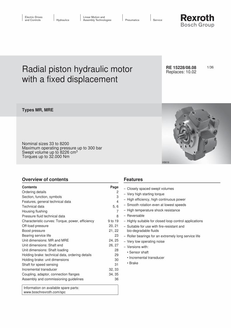
1/36 Information on available spare parts: www.boschrexroth.com/spc Radial piston hydraulic motor with a fixed displacement Types MR, MRE Nominal sizes 33 to 8200 Maximum operating pressure up to 300 bar Swept volume up to 8226 cm 3 Torques up to 32.000 Nm RE 15228/08.08 Replaces: 10.02 Overview of contents Features – Closely spaced swept volumes – Very high starting torque – High efficiency, high continuous power – Smooth rotation even at lowest speeds – High temperature shock resistance – Reversable – Highly suitable for closed loop control applications – Suitable for use with fire-resistant and bio-degradable fluids – Roller bearings for an extremely long service life – Very low operating noise – Versions with: • Sensor shaft • Incremental transducer • Brake Contents Page Ordering details 2 Section, function, symbols 3 Features, general technical data 4 Technical data 5, 6 Housing flushing 7 Pressure fluid technical data 8 Characteristic curves: Torque, power, efficiency 9 to 19 Off-load pressure 20, 21 Boost pressure 21, 22 Bearing service life 23 Unit dimensions: MR and MRE 24, 25 Unit dimensions: Shaft end 26, 27 Unit dimensions: Shaft loading 28 Holding brake: technical data, ordering details 29 Holding brake: unit dimensions 30 Shaft for speed sensing 31 Incremental transducer 32, 33 Coupling, adaptor, connection flanges 34, 35 Assembly and commissioning guidelines 36 H5619
Transcript of Radial piston hydraulic motor with a fixed displacement · Radial piston hydraulic motor with a...
1/36
Information on available spare parts: www.boschrexroth.com/spc
Radial piston hydraulic motor with a fixed displacement
Types MR, MRE
Nominal sizes 33 to 8200Maximum operating pressure up to 300 barSwept volume up to 8226 cm3
Torques up to 32.000 Nm
RE 15228/08.08Replaces: 10.02
Overview of contents Features
– Closely spaced swept volumes– Very high starting torque– High efficiency, high continuous power– Smooth rotation even at lowest speeds– High temperature shock resistance– Reversable– Highly suitable for closed loop control applications– Suitable for use with fire-resistant and
bio-degradable fluids– Roller bearings for an extremely long service life– Very low operating noise– Versions with: •Sensorshaft •Incrementaltransducer •Brake
Contents PageOrdering details 2Section, function, symbols 3Features, general technical data 4Technical data 5, 6Housing flushing 7Pressure fluid technical data 8Characteristic curves: Torque, power, efficiency 9 to 19Off-load pressure 20, 21Boostpressure 21,22Bearingservicelife 23Unit dimensions: MR and MRE 24, 25Unit dimensions: Shaft end 26, 27Unit dimensions: Shaft loading 28Holding brake: technical data, ordering details 29Holding brake: unit dimensions 30Shaft for speed sensing 31Incremental transducer 32, 33Coupling, adaptor, connection flanges 34, 35Assembly and commissioning guidelines 36
H5619
FeaturesOrdering detailsSection, functionSymbolsMR and MRE supplementary featuresTechnical dataTechnical data Technical data Flushing of housingPressure fluid technical dataCharacteristic curves Characteristic curves Characteristic curves Characteristic curves Characteristic curves Characteristic curves Characteristic curves Characteristic curves Characteristic curves Characteristic curves Characteristic curves Characteristic curves Characteristic curves Characteristic curvesBearingservicelifeUnit dimensions: MR and MRE Unit dimensions: MR and MRE Unit dimensions: shaft variations MR and MRE Unit dimensions: shaft variations MR and MRE Shaft loadingHolding brake: technical data, ordering detailsOrdering detailsHolding brake: unit dimensions Sensor shaft for speed sensing – connections Incremental transducer - introductionUnit dimensions Incremental transducer - connection circuitTechnical dataAccessories Accessories Assembly and commissioning guidelines

2/36 Bosch Rexroth AG Hydraulics MR, MRE RE 15228/08.08
Ordering details
Motor type MR (standard 250 bar continuous) = MR MRE (expanded 210 bar continuous) = MRESwept volume NS BSMotor type MR32.1 cm3 – NS33 – A = 33A56.4 cm3 – NS57 – A = 57A72.6 cm3 – NS73 – B = 73B92.6 cm3 – NS93 – B = 93B109.0 cm3 – NS110 – B = 110B124.7 cm3 – NS125 – C = 125C159.7 cm3 – NS160 – C = 160C191.6 cm3 – NS190 – C = 190C250.9 cm3 – NS250 – D = 250D304.1 cm3 – NS300 – D = 300D349.5 cm3 – NS350 – E = 350E451.6 cm3 – NS450 – E = 450E607.9 cm3 – NS600 – F = 600F706.9 cm3 – NS700 – F = 700F1125.8 cm3 – NS1100 – G = 1100G1598.4 cm3 – NS1600 – H = 1600H1809.6 cm3 – NS1800 – H = 1800H2393.0 cm3 – NS2400 – I = 2400I2792.0 cm3 – NS2800 – I = 2800I3636.8 cm3 – NS3600 – L = 3600L4502.7 cm3 – NS4500 – L = 4500L6460.5 cm3 – NS6500 – M = 6500M6967.2 cm3 – NS7000 – M = 7000MMotor type MRE332.4 cm3 – NS330 – D = 330D497.9 cm3 – NS500 – E = 500E804.2 cm3 – NS800 – F = 800F1369.5 cm3 – NS1400 – G = 1400G2091.2 cm3 – NS2100 – H = 2100H3103.7 cm3 – NS3100 – I = 3100I5401.2 cm3 – NS5400 – L = 5400L8226.4 cm3 – NS8200 – M = 8200M
Shaft end Splined shaft to DIN ISO 14 = N1 Splined shaft to DIN 5480 = D1Cylindrical shaft with key = P1Hollow shaft, internal spline to DIN 5480 = F1
Further details in clear textControl
N = Standardclockwise rotation, inlet in A
anti-clockwiserotation,inletinBS = Control rotated
clockwiserotation,inletinB anti-clockwise rotation, inlet in A
Connection flange N1 = Without connection flange C1 = Pipe threadS1 = SAE standard pressure range metricT1 = SAE standard pressure range UNC
SealsN1 = NBRsealssuitablefor
HLP mineral oil to DIN 51524 part 2 V1 = FKM seals F1 = Shaft seal ring for max. 15 bar housing
pressure,NBRsealsU1 = Without shaft seal ring for mounting
thebrake,NBRsealsSpeed sensor
(2nd shaft end) see page 31 N1 = Without speed sensor Q1 = Cylindrical shaft Ø 8 mmM1 = Mono directional incremental transducerB1 = Bi-directionalincrementaltransducer
*
Ordering example:MR 300D-D1N1N1C1N
For brake ordering details see page 29

Hydraulics Bosch Rexroth AGRE 15228/08.08 MR, MRE 29/36
Brake typeOld
B190 B300 B450 B700 B1100 B1800 B2800B125N B180N B265N B400N B620N B1140N B1710N
Static brake torque T Nm 1250 1800 2650 4000 6200 11400 17100
Dynamic brake torque 1) T Nm 650 1200 1450 2200 4200 6250 12000
Release pressure p bar 28 28 27 27 27 30 30
Max. operating pressure p bar 420 420 420 420 420 420 420
Moment of inertia J kg x m2 0.0047 0.0062 0.029 0.043 0.061 0.20 0.27
Weight m kg 32 39 54 74 100 158 262
Cross reference motor type MR/MRE 125 250 350 600 1100 1600 2400
160 300 450 700 1400 1800 2800
190 330 500 800 2100 3100
(For applications outside these parameters, please consult us!)
1) The brake may only be dynamically loaded for a short period of time (e.g. emergency stop).
Holding brake: technical data, ordering details
Ordering details
Ordering example:LAMELLENBREMSE -B190-N1D1V1
LAMMELLENBREMSE *
Multiple disc brakeBrakesize = B190(see table above)Shaft type - output shaft end, dimensions as for the motor Splined shaft to DIN ISO14 = N1Splined shaft to DIN 5480 = D1Shaft type - input shaft end, can be mounted to motor with shaft end Splined shaft to DIN 5480 = D1
Further details in clear textSeals
N1 = NBRseals,suitableforHLPmineraloil to DIN 51524 part 2
V1 = FKM seals