RADARSAT-1/RADARSAT-2/ENVISAT Mission Status Adrian Bohane IICWG St. Petersburg April 2003.
Upload
shanon-barnettCategory
view
215download
0
RADARSAT Constellation Mission: “The Making of”
Alain Carrier, Director Earth Observation Projects
RCM Project Manager
Representation courtesy of MDA Systems Ltd

Outline
2
• Project Description
• Design Parameters
• Nomenclature and Outcome
• System Description
• Project Status
• Industrial Team

Outline
3
• Project Description
• Design Parameters
• Nomenclature and Outcome
• System Description
• Project Status
• Industrial Team

• Scalable Constellation of three small SAR1 satellites
• Primary objective is to support the operational requirements
of Canadian Government departments
• Canadian Government-owned and operated
• Prime contractor: MDA Systems Ltd
4
RCM Description
(1) Synthetic Aperture Radar

• Space Segment Three satellites (Bus, SAR
payload, AIS)
Ground support equipment
(mechanical, electrical)
• Launch Segment Launch system Launch interface Supporting equipment
• Ground Segment Order Handling
Mission Planning
Spacecraft Control
S-band/X-band Grd Terminal
Reception and Archiving
Product Generation
Image Quality
Spacecraft Simulator
RCM Description – Three Segments
5

Outline
6
• Project Description
• Design Parameters
• Nomenclature and Outcome
• System Description
• Project Status
• Industrial Team

• Continuity of C-Band SAR for Operational Users
• Improved revisit over wide areas
• Responsive Ground Segment (Fast tasking and latency)
• Smaller, more cost efficient satellite development
• Improved reliability (i.e. redundancy and scalability)
• Evolution from RADARSAT-2 to wider Operational use
7
Design Parameters – Key Drivers

Design Parameters – Mission Requirements
8
• Three satellites with a potential of six
• Average daily coverage of Canadian waters and regular land coverage
• Average daily global access
• Data analyzed in near real time for operational applications
• 4-day Coherent Change Detection using SAR interferometry
• Gradual implementation with two launches separated by16 months
• Gradual replacement of aging satellites
RADARSAT Constellation daily coverage
RADARSAT-1 or 2 daily coverage

Outline
9
• Project Description
• Design Parameters
• Nomenclature and Outcome
• System Description
• Project Status
• Industrial Team

• Phase 0/A – Initiation and Planning
Opportunity Assessment
Advanced studies and concept design
Industrial capability establishment
Critical technology risk reduction
Preliminary cost and schedule estimates
Development & confirmation of requirements
• Phase B – Preliminary Definition
Detailed requirements flowed down
Risk reduction activities continued
Preliminary design cycle completed
Launch environment defined
Mission Preliminary Design Review
Nomenclature and Outcome– Phases A and B
10

• Phase C – Detailed Definition
Completes design of all spacecraft elements
Establishes implementation baseline
Baseline launch vehicle selected
LLI and associated NRE initiated
Ground segment subsystem requirements established
Ground segment Preliminary Design Review
Mission Critical Design Review
• Phase D – Implementation
Manufacturing, AIT1, launch & commissioning of each spacecraft
Design, manufacturing, AIT of ground segment
Operations development
Training of operations & maintenance personnel
Constellation Commissioning Complete Review
Nomenclature and Outcome– Phases C and D
(1) Assembly, Integration & Test11
• Payload Critical Design Review SW CDR Power Distribution Unit CDR T/R module CDR Payload Electrical Model complete Antenna CDR Tile Controller CDR Payload Controller Unit CDR Central Electronic Unit CDR AIS PDR
• Mission AIT Planning AIT Dev Plan
• Ops Development Ops Dev Review Draft LEOP plan and Rehearsal plan
• Bus Critical Design Review Power CDR Attitude Determination & Ctrl Syst. CDR Power Control Unit Qual. Status Review Propulsion CDR MGSE CDR SW CDR Command & Data Handling QSR Thermal CDR Communication CDR Structural CDR Harness CDR
• Ground Segment Development GS PDR SIM PDR SCS PDR System Requirements Review for:
Restoration & Archiving / Product Generation / Image Quality subsystems
Order Handling / Mission Planning subsystem
Nomenclature and Outcome– Phase C Milestones
Mission Critical Design Review

• Ground Segment Final Acceptance Review
• Bus, Payload & S/C Test Readiness Review
• Manufacturing Readiness Review
• Mission Preliminary Acceptance Review
• Operations Readiness Review
• Flight Readiness Review• Commissioning Complete
Review – Proto-Flight Model• Commissioning Complete
Review (Flight Model 1, Flight Model 2)
• Constellation Commissioning Complete Review
Nomenclature and Outcome– Phase D Milestones
13

Nomenclature and Deliverables – Sequencing
14
Launch 1
Launch 2

Phase C Milestones
Phase C
Outline
16
• Project Description
• Design Parameters
• Nomenclature and Outcome
• System Description
• Project Status
• Industrial Team
17
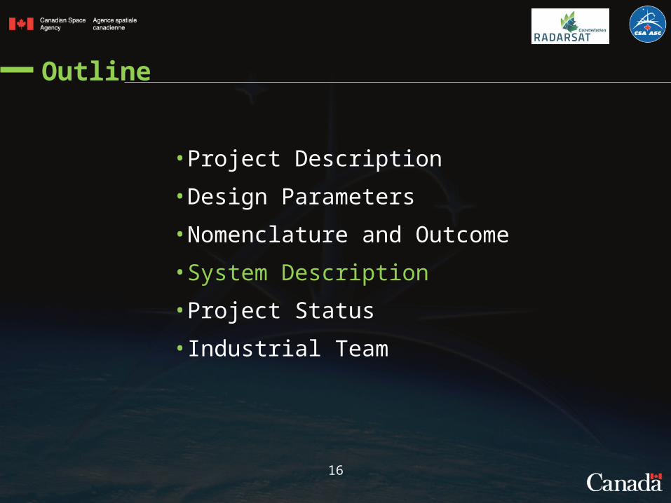
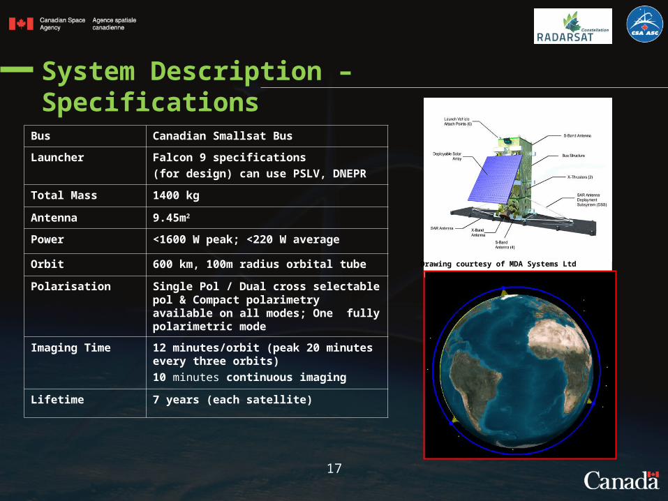
System Description – Specifications
Bus Canadian Smallsat Bus
Launcher Falcon 9 specifications (for design) can use PSLV, DNEPR
Total Mass 1400 kg
Antenna 9.45m2
Power <1600 W peak; <220 W average
Orbit 600 km, 100m radius orbital tube
Polarisation Single Pol / Dual cross selectable pol & Compact polarimetry available on all modes; One fully polarimetric mode
Imaging Time 12 minutes/orbit (peak 20 minutes every three orbits)10 minutes continuous imaging
Lifetime 7 years (each satellite)
Drawing courtesy of MDA Systems Ltd
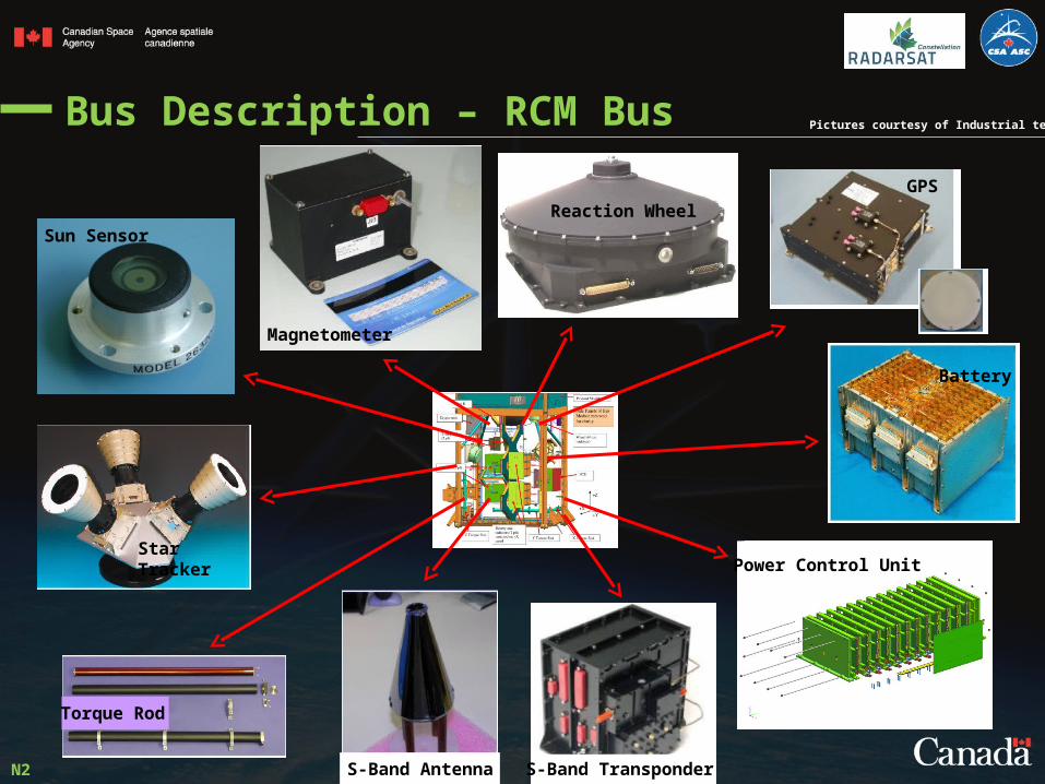
Bus Description – RCM Bus
Sun Sensor
Magnetometer
Reaction Wheel
Star Tracker
Battery
Power Control Unit
GPS
S-Band TransponderS-Band Antenna
Torque Rod
N2
Pictures courtesy of Industrial team

System Description – RCM Payload
SAR Antenna
Power Distribution Unit
Tx/Rx Module
Tile Controller Unit
Mass Memory Unit
Central Electronic Unit
Payload Controller Unit
N2
AIS
Representations courtesy of Industrial team

St-Hubert (X+S), Svalbard (X+S), Masstown and Aldergrove (X)
System Description – Ground Segment Baseline
20

Outline
21
• Project Description
• Design Parameters
• Nomenclature and Outcome
• System Description
• Project Status
• Industrial Team

Now
Project Status – Schedule and Cost Distribution
22
N
Ops Phase
Phase D
Y1 Y3Y2 Y9Y4 Y7Y5 Y8Y6 Y10 Y13 Y15Y14Y12Y11
Phase APhase B

Outline
23
• Project Description
• Design Parameters
• Nomenclature and Outcome
• System Description
• Project Status
• Industrial Team

Industrial Team
24

• Typical contract structures:
Cost reimbursable (Progress payments)
Firm Fix Price (Milestone payments)
• Canadian content
• Regional distribution
• Earned Value Management
Industrial Team – Contract Arrangement & Control
25
N
Back Up

RCM Description – Primary Objective
• Support the operational requirements of Canadian Government departments in the delivery of services to Canadians in areas of :
• Maritime surveillance
• Ecosystem monitoring
• Disaster management
N

28
System Description – Spacecraft
N

System Description – Spacecraft Exterior Layout

• High-grade crypto on-board the satellites (Crypto Flight Unit) and on the ground (Crypto Ground Unit) to encrypt all commands and telemetry as well as classified science data (as needed)
• RCM will be capable of handling both classified and unclassified Orders and Products
• Unclassified science data will be encrypted to a lesser level (commercial grade)
• Crypto Ground Units will encrypt commands originating from the CSA operations center as well as decrypt classified and unclassified telemetry and science data
Crypto Ground Unit
Crypto Flight Unit
System Description – Security Level
30
Representations courtesy of Industrial team

• An additional payload is being
considered to receive AIS signal
• Would allow real time coherent
acquisition of AIS signal with SAR
image to identify vessels of interest.
Payload Description – Automatic Identification of Ship (AIS)
31

Payload Description – Model Philosophy of Main Units
32

Bus Description – Model Philosophy of Bus Ssyst/Unit
33

RCM Description – System Diagram
34
1
(1) SXGT: S/X Band Ground Terminal

• Project Management– Schedule, Cost, Risks– Technical progress & integration (Space & Ground)– Implementation analysis– Intellectual Property– Mission Management– Data Policy– Data Utilization– Application Development– Commercialization License– Governance (Approval and Reporting)
35
Roles & Responsibilities – PMO Level Integration
35

Project Status – Requirements Evolution
36

[SYS2010] Imaging Time Per Orbit. Each spacecraft in the system shall be capable of imaging at any time when all of the following constraints are satisfied:
1.No more than 36 minutes of imaging in any moving window time period of duration equal to three orbital periods.
2.No more than 20 minutes of imaging in any moving window time period of duration equal to one orbital period.
3.No more than 10 minutes of imaging in any moving window time period of duration 20 minutes.
4.The spacecraft is not in eclipse.

[SYS3100] AIS Operating Time Per Orbit. Each spacecraft in the system shall be capable of collecting AIS at any time when all of the following constraints are satisfied:
1.No more than 51 minutes of AIS collection in any moving window time period of duration equal to three orbital periods.
2.No more than 25 minutes of AIS collection in any moving window time period of duration equal to one orbital period.
3.No more than 15 minutes of AIS collection in any moving window time period of duration 25 minutes.