
Rachel Sharp Corinne Packard Isaac Feitler Hao Hu Project Update April 10, 2003 Massachusetts...
26
Rachel Sharp Rachel Sharp Corinne Corinne Packard Packard Isaac Feitler Isaac Feitler Hao Hu Hao Hu Project Update April 10, 2003 Massachusetts Institute of Massachusetts Institute of Technology Technology 3.082 3.082
-
date post
20-Dec-2015 -
Category
Documents
-
view
218 -
download
3
Transcript of Rachel Sharp Corinne Packard Isaac Feitler Hao Hu Project Update April 10, 2003 Massachusetts...

Rachel SharpRachel SharpCorinne PackardCorinne Packard
Isaac FeitlerIsaac FeitlerHao HuHao Hu
Project Update
April 10, 2003
Massachusetts Institute of TechnologyMassachusetts Institute of Technology3.0823.082

TodayToday
Update on progressUpdate on progressCapacitor bankCapacitor bank
CastingCasting
Other machiningOther machining
CalculationsCalculations
Deformation mechanismsDeformation mechanisms
Next stepsNext steps

Revised Gantt ChartRevised Gantt Chart
11 22 33 44 55 66 77 88 99 1010 1111 1212 1313 1414
Week
Pressure Vessel Capacitor Bank Mold Electrohydraulic forming Final Presentation
Vessel design and parts acquisition
Pressure Vessel assemblyCAD
Casting of moldElectrohydraulic test
Funnel formation
Final part formation
Presentation preparation
Capacitor bank acquisition
Bre
ak
Die printing

Capacitor Bank UpdateCapacitor Bank UpdateMagneform machine has been supplied with Magneform machine has been supplied with power, and troubleshooting started but has not power, and troubleshooting started but has not progressed very far.progressed very far.Low-voltage, high capacitance 1kJ capacitor Low-voltage, high capacitance 1kJ capacitor bank has been acquired. bank has been acquired. We still expect measurable results, but we won’t We still expect measurable results, but we won’t know to what extent until we test it.know to what extent until we test it.1kJ capacitor bank for at least the time being. 1kJ capacitor bank for at least the time being. Time permitting, we may still pursue higher-Time permitting, we may still pursue higher-energy deformation.energy deformation.

Creating the DiesCreating the Dies
CAD files of dies created with SolidworksCAD files of dies created with Solidworks
Dies are printed 3D printerDies are printed 3D printerFrom MIT & Z-corpFrom MIT & Z-corp
Prints composed of starchPrints composed of starch
Creation of Plaster Mold Creation of Plaster Mold
Casting with Bronze Casting with Bronze

Lost Wax CastingLost Wax Casting
A positive print of final shape is created A positive print of final shape is created with 3D printing with 3D printing
Ceramic shells are created to surround the Ceramic shells are created to surround the 3D print 3D print
Molten Bronze is poured into the shellMolten Bronze is poured into the shell
As the starch burns out, the molten bronze As the starch burns out, the molten bronze takes the shape of the positive die shape takes the shape of the positive die shape

Pressure Vessel Design ChangesPressure Vessel Design ChangesStainless steel pipe plugs Stainless steel pipe plugs replace cast iron plugsreplace cast iron plugsHole depth for pipe plugs is 0.7” Hole depth for pipe plugs is 0.7” the min. wall thickness of the the min. wall thickness of the vessel is 0.5”vessel is 0.5”Inter-electrode spacing now Inter-electrode spacing now 2.75”2.75”Teflon insulation design slightly Teflon insulation design slightly modifiedmodifiedAluminum pipe purchased for Aluminum pipe purchased for testing of assembly without a testing of assembly without a diedie
Machining has been slow due to the robustness of the Machining has been slow due to the robustness of the materials used. Despite this, the vessel is nearly complete.materials used. Despite this, the vessel is nearly complete.
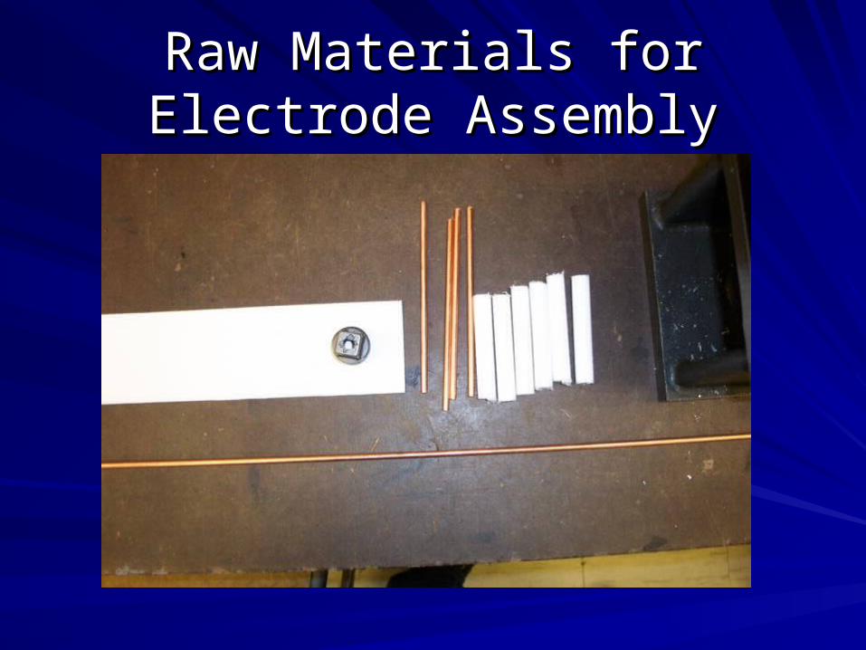
Raw Materials for Electrode Raw Materials for Electrode AssemblyAssembly

Final Electrode AssemblyFinal Electrode Assembly

Al Pipe Ring for Free ExpansionAl Pipe Ring for Free Expansion

Drilling Electrode Holes in Drilling Electrode Holes in Pressure VesselPressure Vessel
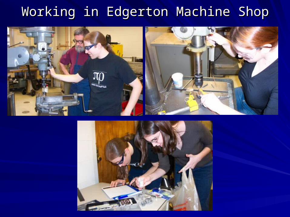
Working in Edgerton Machine ShopWorking in Edgerton Machine Shop

Part failure calculationsPart failure calculationsPartPart MaterialMaterial Stress Stress
statestateStrengthStrength
(ksi)(ksi)Area Area (in(in22))
LoadLoad(lbs)(lbs)
Pressure Pressure to fail to fail (psi)(psi)
CommentComment
VesselVessel AISI 1045AISI 1045 ComplexComplex 5555 -------- ---------- 18,00018,000 Thick Thick spheresphere
PlugPlug 304 S.S.304 S.S. Tens?Tens? -------- -------- ---------- 3,0003,000 Rating for Rating for intact plugintact plug
InsulationInsulation TeflonTeflon Comp.Comp. 33 0.1690.169 507507 2,5002,500 ExtrusionExtrusion
ElectrodeElectrode 110 Cu110 Cu Tens.Tens. 4444 0.0160.016 709709 25,60025,600 Around pinAround pin
WasherWasher 18-8 S.S.18-8 S.S. CompComp ------ -------- -------- ---------- oughtn’t failoughtn’t fail
PinPin 416 S.S.416 S.S. 2xShear2xShear 130130 0.0030.003 797797 28,50028,500
GasketGasket NeopreneNeoprene -------- ------ ------ ------ ------ oughtn’t failoughtn’t fail
WorkpieceWorkpiece 5052 Al5052 Al Biax. Biax. Tens.Tens.
1313 -------- ---------- 1,0001,000 Thin Thin SphereSphere

Leak-Before-Break CriteriaLeak-Before-Break Criteria
Wall thickness > critical crack sizeWall thickness > critical crack size, and a crack , and a crack in the vessel reaches the critical crack size, then in the vessel reaches the critical crack size, then the vessel will fail in a “fast fracture mode”the vessel will fail in a “fast fracture mode”
Wall thickness < critical crack sizeWall thickness < critical crack size, then the , then the crack will propagate through the wall and the crack will propagate through the wall and the vessel will leak (reducing the internal pressure) vessel will leak (reducing the internal pressure) before a “fast fracture” can occur.before a “fast fracture” can occur.

CalculationsCalculations
Stress-intensity factor (also called fracture Stress-intensity factor (also called fracture toughness) toughness) D. Broek, Elementary Engineering Fracture Mechanics, Martinus D. Broek, Elementary Engineering Fracture Mechanics, Martinus Nijhoff Publishers, 1982. Pg.393 ]Nijhoff Publishers, 1982. Pg.393 ]
aacc is critical crack size, is critical crack size, yy is yield strength, is yield strength, generally is 1 in the worst case.generally is 1 in the worst case.
Solve for aSolve for acc
cysIc a K
21
ys
Icc
ασ
K
π a

Calculations, continued:Calculations, continued:
[[D. Fryer,High Pressure Vessels, Chapman and Hall, 1997, p.123D. Fryer,High Pressure Vessels, Chapman and Hall, 1997, p.123 ]]
Y.P.Y.P. is the yield strength in ksi is the yield strength in ksi
CVN is the Charpy V-notch adsorbed energy in ft-lbsCVN is the Charpy V-notch adsorbed energy in ft-lbs
KKIcIc is in ksi-in is in ksi-in22
For AISI 1045 steel, CVN varies widely with hardness.For AISI 1045 steel, CVN varies widely with hardness.
We choose a low value of hardness (225 Brinell) and We choose a low value of hardness (225 Brinell) and get a CVN of 38-48 at 50get a CVN of 38-48 at 50°F°F
⎟⎟⎠
⎞⎜⎜⎝
⎛⎟⎟⎠
⎞⎜⎜⎝
⎛=
45
2Y.P.
Y.PIc
ó.CVN - óK

Calculations, continued 2:Calculations, continued 2:
For CVN = 38, For CVN = 38, Y.P.Y.P. = 55 ksi, K = 55 ksi, KIcIc = 98.5: = 98.5: aac c = 1”= 1”
Neglecting the holes for the electrodes Neglecting the holes for the electrodes which pierce the vessel completely, the which pierce the vessel completely, the thinnest and most crack prone area of the thinnest and most crack prone area of the vessel is 0.5” thickvessel is 0.5” thickThe The vessel will leak before burstingvessel will leak before bursting at the at the areas we expect to be weakest and most areas we expect to be weakest and most crack-prone.crack-prone.

Strain and DeformationStrain and Deformation
ε ε
Sample responds to strain by necking
I. II. III.AF AF A
F
low lowhighRegion II. Smaller area greater σ
Image from http://www.sri.com/poulter/fe_modeling/fem_figures/fig_wf3.html

Stopping the Downward SpiralStopping the Downward Spiral
To overcome this weakening cycle, To overcome this weakening cycle, necking must be suppressednecking must be suppressed
Work HardeningWork Hardening
Phonon DragPhonon Drag
Higher ε
Higher σLower A

Work HardeningWork Hardening
At any strain rate-At any strain rate-
Stress causes dislocations to move
Strain is the macroscopic result of dislocation activity
In the necked region,
ε is higher dislocation activity is higher
Image from http://newt.phys.unsw.edu.au/~epe/1250.L9/1250.L9.small.html

Work HardeningWork Hardening
Increased dislocation activity creates Increased dislocation activity creates tangles which increase the yield tangles which increase the yield
stress stress of the materialof the material
Ultimately, increased Ultimately, increased εε increased increased σσyy,,
So if So if σσy IIy II > > σσy I, IIIy I, III , Regions I and III will yield , Regions I and III will yield
first and first and necking will be suppressednecking will be suppressed..

Phonon DragPhonon Drag
““Inertial Effects” I=mvInertial Effects” I=mv
Smaller A in II Smaller A in II yielding in the region yielding in the region V V22>V>V11
I. II. III.
ε ε
V1 V2 V1
dtdxV = )(
0
01
xxx
dtd
dtd −== εε&
What is the result of having a high strain rate?

Phonon DragPhonon Drag
Back to dislocation movement-Back to dislocation movement-
┴
┴ moves
E
Stress lowers the activation energy required to make a dislocation move
Remember that phonons are lattice vibrations.
* But there is still a critical time length when probability favors movement

Phonon DragPhonon Drag
At low strain rates, probability is not limitingAt low strain rates, probability is not limiting
Dislocations move smoothlyDislocations move smoothly
At high strain rates, probability is limitingAt high strain rates, probability is limiting
Dislocation move jerkilyDislocation move jerkilyBTbA ε
2
Phonon Drag Coefficient, B, increases with temperature, is very different for different crystal systems, and has dependences on many other microscopic variables
Phonon Drag must be the rate limiting step in order for this equation to hold!

Review of Deformation Review of Deformation MechanismsMechanisms
Work HardeningWork HardeningAny strain rateAny strain rate
Phonon DragPhonon DragHigh strain ratesHigh strain rates
σy σy
ε dε/dt
At very high strain rates, Phonon Drag becomes an important factor and allows for greater elongation than work hardening alone