
R5 Tec Black, 1st Stage – Service and Repair...
34
R5 Tec Black DIN / Yoke 1 st Stage Service and Repair Manual Version 1.1, May 1, 2014
-
Upload
truongphuc -
Category
Documents
-
view
218 -
download
4
Transcript of R5 Tec Black, 1st Stage – Service and Repair...

R5 Tec Black DIN / Yoke1st Stage
Service and Repair Manual
Version 1.1, May 1, 2014
DisclaimerThis document is proprietary to Scubatech Sp. z o. o. ("Scubatech") and no ownership rights are hereby transferred. No part of this document shall be used, reproduced, translated, converted, adapted, stored in a retrieval system, communicated or transmitted by any means, for any commercial purpose, including without limitation, sale, resale, licence, rental or lease, without the prior express written consent of Scubatech.
Scubatech does not make any representations, warranties or guarantees, express or implied, as to the accuracy or completeness of the manual. Users must be aware that updates and amendments will be made from time to time to the manual. It is the user's responsibility to determine whether there have been any such updates or amendments. Neither Scubatech nor any of its directors, officers, employees or agents shall be liable in contract, tort or in any other manner whatsoever to any person for any loss, damage, injury, liability, cost or expense of any nature, including without limitation incidental, special, direct or consequential damages arising out of or in connection with the use of the manual.
Should you have any questions or comments regarding this manual, please contact:
Scubatech Sp. z O.O.Ul. Lubieszyńska 272-006 MierzynPoland
Tel/Fax: +48 91 453 00 17Mobile: +48 605 662 795Email: [email protected]: www.scubatech.pl

R5 Tec Black, 1st Stage – Service and Repair Manual
Table of ContentsDisclaimer.............................................................................................................................. 2
Table of Contents.................................................................................................................. 3
Introduction........................................................................................................................... 5
Safety Precautions................................................................................................................ 6
Definition of Notes, Warnings and Cautions.........................................................................6
General Procedures.............................................................................................................. 7
Maintenance Schedules...................................................................................................... 7
Documentation.................................................................................................................... 7
Initial Inspection................................................................................................................... 8
Regulator Pre-Test............................................................................................................... 8
Infrequently Used Regulators.............................................................................................. 8
Removing O-Rings.............................................................................................................. 9
About Your Work Area.......................................................................................................... 9
About Tools......................................................................................................................... 10
Air Nozzle.......................................................................................................................... 10
Allen Keys.......................................................................................................................... 10
Dentist Tools for O-Ring Removal...................................................................................... 10
Dentist Tools for O-Ring Placement................................................................................... 11
Holding Tool....................................................................................................................... 11
Setting Tool 2nd Stage....................................................................................................... 11
Low Pressure Gauge......................................................................................................... 12
Pen Knife........................................................................................................................... 12
Pliers................................................................................................................................. 12
Ring Spanner (Double)...................................................................................................... 13
Ring Spanner (Single)....................................................................................................... 13
Spanners........................................................................................................................... 13
Special Tool for 2nd Stages............................................................................................... 13
Torque Wrench.................................................................................................................. 14
Cleaning Agents and Lubricants....................................................................................... 15
Schematic Drawing and Spare Parts................................................................................. 16
R5 Tec DIN / Yoke.............................................................................................................. 16
Disassembly........................................................................................................................ 18
Before Disassembling the First Stage................................................................................ 18
Step 1 – Removing the Plugs............................................................................................ 18
Step 2 – Removing the O-Rings........................................................................................ 18
Step 3 – Holding Tool Installation (recommended).............................................................18
Page 3
R5 Tec Black, 1st Stage – Service and Repair Manual
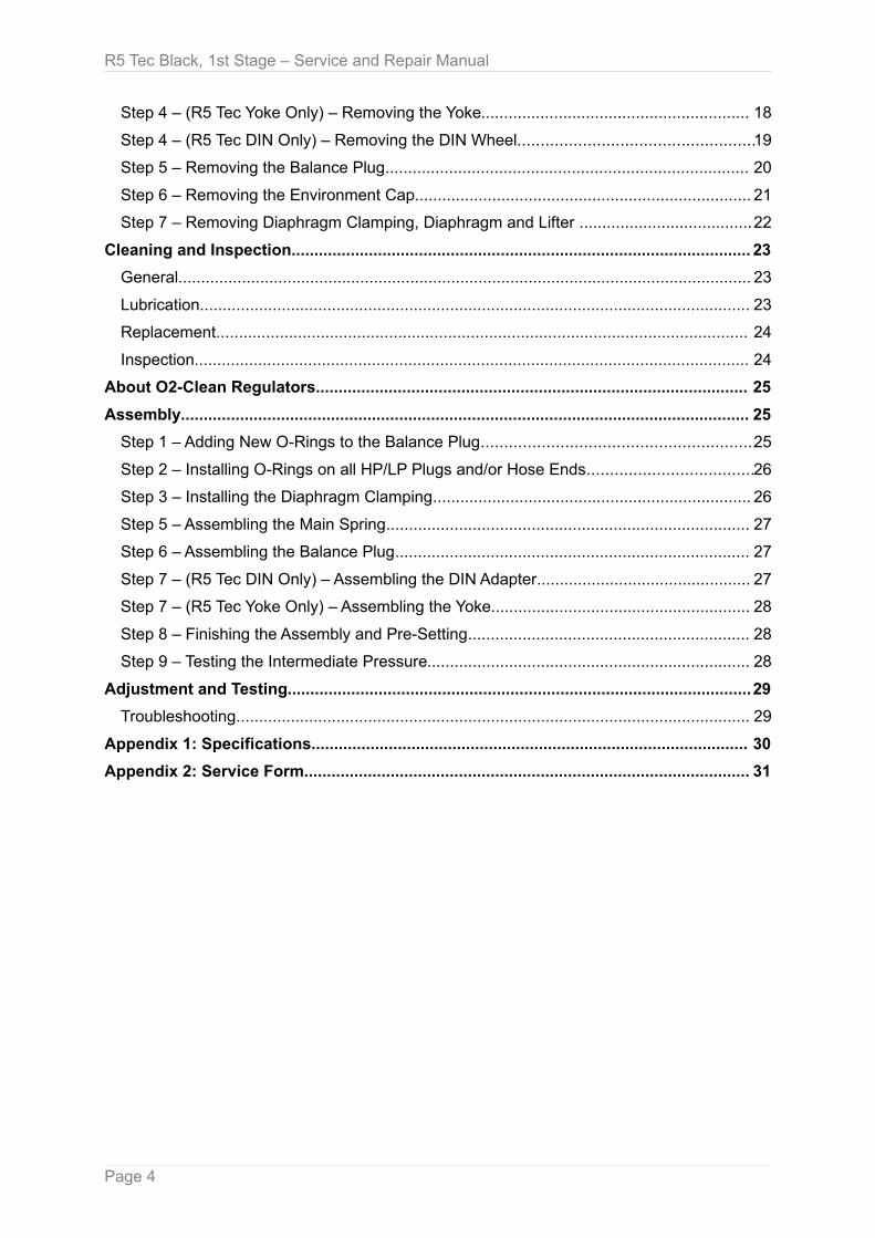
Step 4 – (R5 Tec Yoke Only) – Removing the Yoke........................................................... 18
Step 4 – (R5 Tec DIN Only) – Removing the DIN Wheel...................................................19
Step 5 – Removing the Balance Plug................................................................................ 20
Step 6 – Removing the Environment Cap.......................................................................... 21
Step 7 – Removing Diaphragm Clamping, Diaphragm and Lifter ......................................22
Cleaning and Inspection..................................................................................................... 23
General.............................................................................................................................. 23
Lubrication......................................................................................................................... 23
Replacement..................................................................................................................... 24
Inspection.......................................................................................................................... 24
About O2-Clean Regulators............................................................................................... 25
Assembly............................................................................................................................. 25
Step 1 – Adding New O-Rings to the Balance Plug...........................................................25
Step 2 – Installing O-Rings on all HP/LP Plugs and/or Hose Ends....................................26
Step 3 – Installing the Diaphragm Clamping...................................................................... 26
Step 5 – Assembling the Main Spring................................................................................ 27
Step 6 – Assembling the Balance Plug.............................................................................. 27
Step 7 – (R5 Tec DIN Only) – Assembling the DIN Adapter............................................... 27
Step 7 – (R5 Tec Yoke Only) – Assembling the Yoke......................................................... 28
Step 8 – Finishing the Assembly and Pre-Setting.............................................................. 28
Step 9 – Testing the Intermediate Pressure....................................................................... 28
Adjustment and Testing......................................................................................................29
Troubleshooting................................................................................................................. 29
Appendix 1: Specifications................................................................................................ 30
Appendix 2: Service Form.................................................................................................. 31
Page 4
R5 Tec Black, 1st Stage – Service and Repair Manual
IntroductionScubatech regulators are the result of many years of research and development, and Scubatech has utilized proven materials and design to maximize reliability and performance.
This manual is intended only as a guide for experienced service personnel, who completed a Scubatech service and repair training. It is not intended for self-study or for the user.
Scubatech repair trainings are available periodically to Scubatech dealers.
Servicing and repair at shop level mainly involves cleaning, inspection, adjustment, and replacement of worn parts.
Should you have any questions on any of the procedures, inspections or tests, please contact Scubatech Sp. z. o.o.
Page 5

R5 Tec Black, 1st Stage – Service and Repair Manual
Safety PrecautionsThis manual provides step by step instructions for disassembly, inspection, cleaning, reassembly, and testing of the Scubatech R5 Tec Black regulator (1st stage).
It is recommended, that all steps are followed in the order given. Please read each section completely and carefully PRIOR to carrying out the steps described in that section. This will familiarize you with important precautions to take during each service procedure. Pay close attention to all WARNINGS, CAUTIONS, and NOTES that are intended to draw your attention to items of importance.
Definition of Notes, Warnings and CautionsNoteEmphasizes important information and hints.
WarningIndicates any situation or technique that may result in potential damage to the product, or that renders the product unsafe, if instructions are not followed correctly.
CautionIndicates a procedure or situation, that may result in serious injury or death for either the technician or the user, if instructions are not followed correctly.
Page 6
R5 Tec Black, 1st Stage – Service and Repair Manual
General Procedures
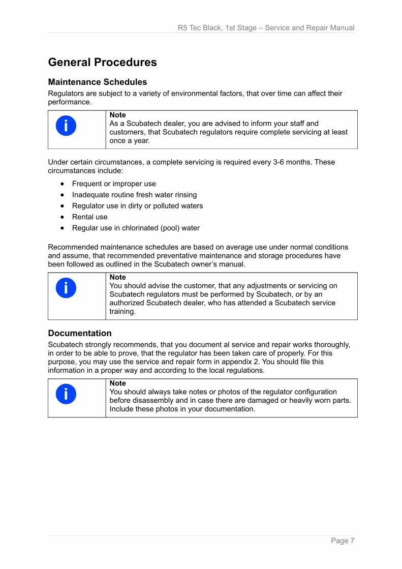
Maintenance SchedulesRegulators are subject to a variety of environmental factors, that over time can affect their performance.
NoteAs a Scubatech dealer, you are advised to inform your staff and customers, that Scubatech regulators require complete servicing at least once a year.
Under certain circumstances, a complete servicing is required every 3-6 months. These circumstances include:
● Frequent or improper use
● Inadequate routine fresh water rinsing
● Regulator use in dirty or polluted waters
● Rental use
● Regular use in chlorinated (pool) water
Recommended maintenance schedules are based on average use under normal conditions and assume, that recommended preventative maintenance and storage procedures have been followed as outlined in the Scubatech owner’s manual.
NoteYou should advise the customer, that any adjustments or servicing on Scubatech regulators must be performed by Scubatech, or by an authorized Scubatech dealer, who has attended a Scubatech service training.
DocumentationScubatech strongly recommends, that you document al service and repair works thoroughly, in order to be able to prove, that the regulator has been taken care of properly. For this purpose, you may use the service and repair form in appendix 2. You should file this information in a proper way and according to the local regulations.
NoteYou should always take notes or photos of the regulator configuration before disassembly and in case there are damaged or heavily worn parts. Include these photos in your documentation.
Page 7
R5 Tec Black, 1st Stage – Service and Repair Manual
Initial InspectionPrior to beginning the service, a preliminary inspection and pre-test of the entire breathing system is recommended. This will help you to identify any problems, that may affect the first stage. This initial inspection should include the following:
Inlet FilterIf the inlet filter in the first stage is discolored, the entire regulator should be completely serviced. Deposits of rust (red powder) or aluminum oxide (gray powder) on the filter may indicate, that water has entered the SCUBA cylinder and caused internal corrosion. In this case, you should notify the customer, that their SCUBA cylinder(s) may be in need of visual inspection, cleaning and testing. Advise your customers, to regularly inspect the inlet filter visually (without dismantling the regulator) for any discoloration or corrosion.
High Pressure (HP) and Low Pressure (LP) HosesInspect the hoses carefully for any signs of cracking, tearing, or excessive abrasion of the outer rubber covering. Remove all protectors (if present) and examine the area around the metal fittings for any damage to the hose. Inspect the fittings for signs of excessive corrosion.
NotePay special attention, when textile (braided) hoses are used. These hoses do not provide an internal support layer and must be replaced, when showing signs of abrasion or damage.
WarningPlease note, that you need to replace hoses with a brand or model according to Scubatech specifications. Failing to do so could void the regulator's CE certificate.
All Chrome Plated PartsInspect these parts for any excessive corrosion, indicating weak or absent chrome plating. Also look for any signs of peeling or flaking of the chrome plating.
Regulator Pre-TestA regulator pre-test should include all tests outlined in the test section ("Assembly, Step 9).This test will assist you in determining, if there are any specific performance deficiencies not mentioned by the customer.
NoteYou should document your findings!
Infrequently Used RegulatorsDo not assume that a regulator is in good condition, because of infrequent use or because it has been in storage. Even under these circumstances, deterioration of the O-rings and corrosion may occur.
Page 8
R5 Tec Black, 1st Stage – Service and Repair Manual
Removing O-RingsWhen removing O-rings, be careful not to damage the regulator surfaces in contact with the O-rings.
WarningTools used to remove O-rings must not have any sharp edges or points that could scratch metal sealing surfaces. Scubatech recommends, that all O-ring removal tools should be made of either brass or plastic.
About Your Work AreaServicing and repair of the regulator should be carried out in a clean well illuminated work area.
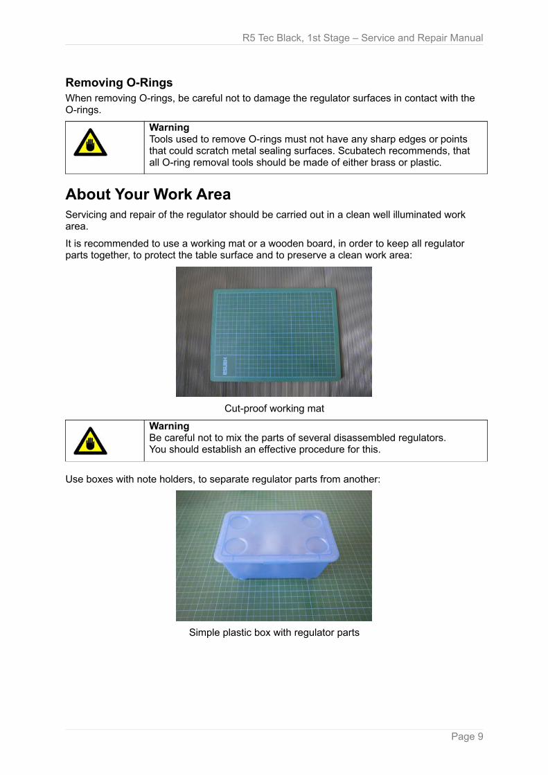
It is recommended to use a working mat or a wooden board, in order to keep all regulator parts together, to protect the table surface and to preserve a clean work area:
Cut-proof working mat
WarningBe careful not to mix the parts of several disassembled regulators.You should establish an effective procedure for this.
Use boxes with note holders, to separate regulator parts from another:
Simple plastic box with regulator parts
Page 9
R5 Tec Black, 1st Stage – Service and Repair Manual
About ToolsSome special tools are required for proper disassembly and reassembly. While Scubatech offers some of them, you will find a variety of similar tools on the market. the following describes the proven tools for regulator servicing.
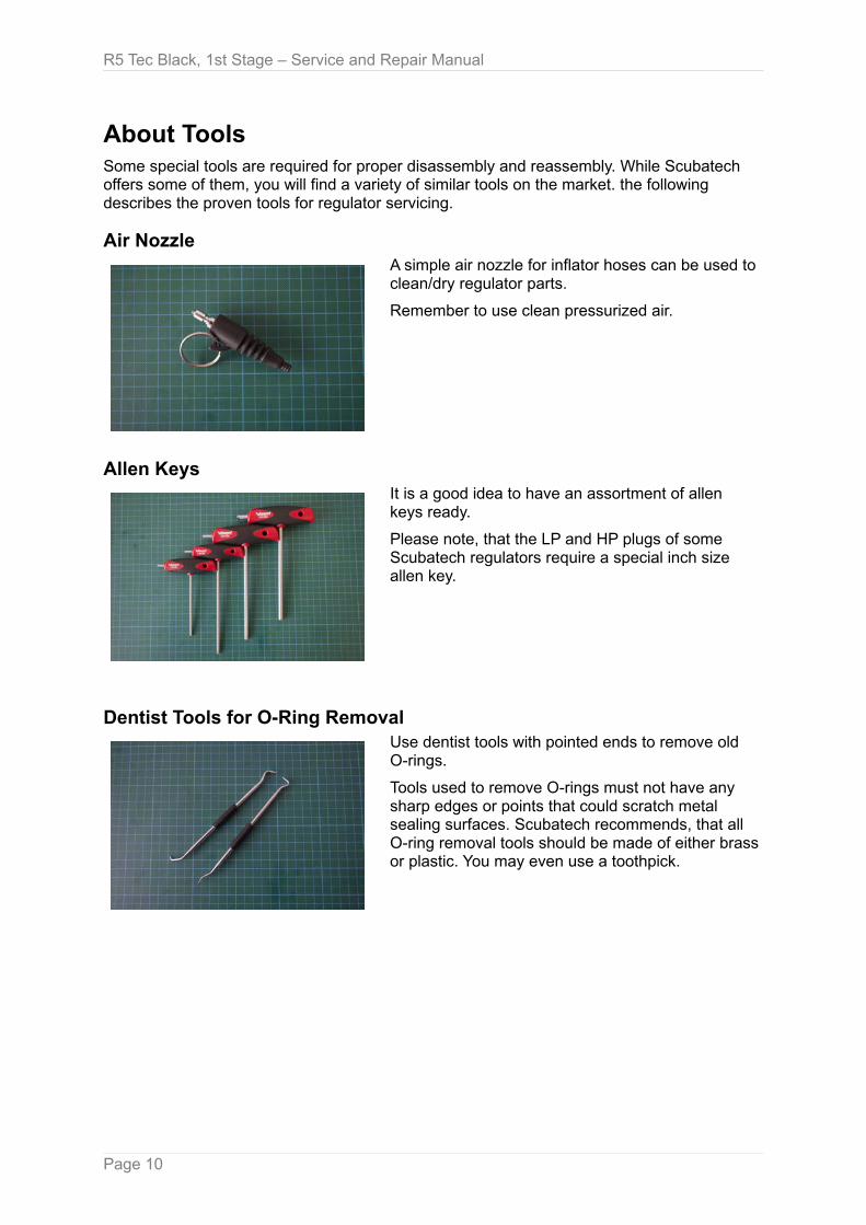
Air NozzleA simple air nozzle for inflator hoses can be used to clean/dry regulator parts.
Remember to use clean pressurized air.
Allen KeysIt is a good idea to have an assortment of allen keys ready.
Please note, that the LP and HP plugs of some Scubatech regulators require a special inch size allen key.
Dentist Tools for O-Ring RemovalUse dentist tools with pointed ends to remove old O-rings.
Tools used to remove O-rings must not have any sharp edges or points that could scratch metal sealing surfaces. Scubatech recommends, that all O-ring removal tools should be made of either brass or plastic. You may even use a toothpick.
Page 10

R5 Tec Black, 1st Stage – Service and Repair Manual
Dentist Tools for O-Ring PlacementUse dentist tools with ball-shaped ends to place new O-rings and Teflon rings.
Holding ToolUse this special holding tool with threads for LP and HP ports in the first stage, in order to fix the 1st stage in a vice.
Make sure, that this tool is always fully screwed in the 1st stage.
Setting Tool 2nd StageThis special tool is used to adjust the "sensitivity" of the second stage.
It is available as an "inline version", installed between MP hose and 2nd stage and as a "standalone version".
Page 11
R5 Tec Black, 1st Stage – Service and Repair Manual
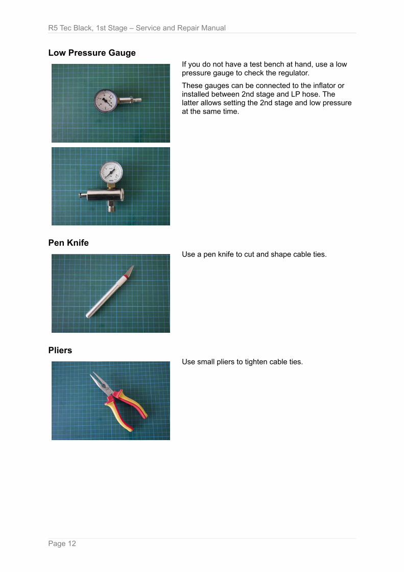
Low Pressure GaugeIf you do not have a test bench at hand, use a low pressure gauge to check the regulator.
These gauges can be connected to the inflator or installed between 2nd stage and LP hose. The latter allows setting the 2nd stage and low pressure at the same time.
Pen KnifeUse a pen knife to cut and shape cable ties.
PliersUse small pliers to tighten cable ties.
Page 12
R5 Tec Black, 1st Stage – Service and Repair Manual
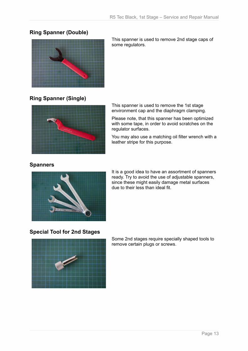
Ring Spanner (Double)This spanner is used to remove 2nd stage caps of some regulators.
Ring Spanner (Single)This spanner is used to remove the 1st stage environment cap and the diaphragm clamping.
Please note, that this spanner has been optimized with some tape, in order to avoid scratches on the regulator surfaces.
You may also use a matching oil filter wrench with a leather stripe for this purpose.
SpannersIt is a good idea to have an assortment of spanners ready. Try to avoid the use of adjustable spanners, since these might easily damage metal surfaces due to their less than ideal fit.
Special Tool for 2nd StagesSome 2nd stages require specially shaped tools to remove certain plugs or screws.
Page 13
R5 Tec Black, 1st Stage – Service and Repair Manual
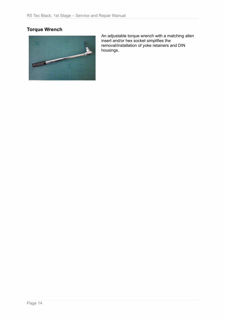
Torque WrenchAn adjustable torque wrench with a matching allen insert and/or hex socket simplifies the removal/installation of yoke retainers and DIN housings.
Page 14

R5 Tec Black, 1st Stage – Service and Repair Manual
Cleaning Agents and LubricantsO-rings should be lubricated with an approved compound (please refer the following table for proper lubricants). O-rings should be lubricated only with a very light film of grease.
WarningUnder no circumstances, use spray (aerosol) lubricants!The aerosol propellant may damage the plastic and rubber components of the regulator, and the lubricant will quickly evaporate, providing little or no lasting benefit.
Description Application
Christo-Lube® MCG-111 Compatible for all O-ring materials
DOW CORNING, 111 Silicone grease Only for NBR O-ring
Crystal Simple Green Industry cleaner
Chrome safe Cleaning oxidized brass
Page 15
R5 Tec Black, 1st Stage – Service and Repair Manual
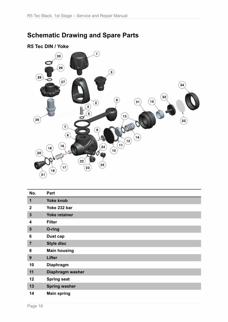
Schematic Drawing and Spare Parts
R5 Tec DIN / Yoke
No. Part
1 Yoke knob
2 Yoke 232 bar
3 Yoke retainer
4 Filter
5 O-ring
6 Dust cap
7 Style disc
8 Main housing
9 Lifter
10 Diaphragm
11 Diaphragm washer
12 Spring seat
13 Spring washer
14 Main spring
Page 16
R5 Tec Black, 1st Stage – Service and Repair Manual
No. Part
15 Adjustment nut
16 HP seat
17 Adjustment spring
18 O-ring
19 O-ring
20 O-ring
21 Balance plug
22 HP O-ring
23 HP plug
24 LP O-ring
25 LP plug
26 DIN housing
27 DIN wheel
28 O-ring
29 DIN retainer
30 O-ring
31 Diaphragm clamping
32 Transmitter
33 Environment disc
34 Environment cap
Page 17
R5 Tec Black, 1st Stage – Service and Repair Manual
Disassembly
Before Disassembling the First Stage● Remove the low pressure second stage hoses.
● Remove the low pressure inflator hose.
● Remove the high pressure hose.
● Remove and discard the O-rings from the male fittings of each hose.
NoteIt is recommended to keep O-rings and other removed parts as a proof of work for the customer.
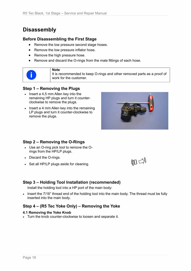
Step 1 – Removing the Plugs● Insert a 4,5 mm Allen key into the
remaining HP plugs and turn it counter-clockwise to remove the plugs.
● Insert a 4 mm Allen key into the remaining LP plugs and turn it counter-clockwise to remove the plugs.
Step 2 – Removing the O-Rings● Use an O-ring pick tool to remove the O-
rings from the HP/LP plugs.
● Discard the O-rings.
● Set all HP/LP plugs aside for cleaning.
Step 3 – Holding Tool Installation (recommended)Install the holding tool into a HP port of the main body:
● Insert the 7/16” thread end of the holding tool into the main body. The thread must be fully inserted into the main body.
Step 4 – (R5 Tec Yoke Only) – Removing the Yoke
4.1 Removing the Yoke Knob● Turn the knob counter-clockwise to loosen and separate it.
Page 18
R5 Tec Black, 1st Stage – Service and Repair Manual
4.2 Disassembling the Yoke RetainerUse a torque wrench with 19 mm hex socket to disassemble the yoke retainer:
● Insert the hex socket with extension into the yoke retainer (from the yoke knob side).
Use a torque wrench with 19 mm hex socket to disassemble the yoke retainer:
● Turn the torque wrench counter-clockwise to loosen the yoke retainer.
● Separate the yoke, the dust cap and the yoke socket from the main body.
● Set the yoke knob, the yoke, the yoke retainer, the dust cap and the style disc aside for cleaning.
● Separate the filter and the O-ring from the yoke retainer and discard.
Step 4 – (R5 Tec DIN Only) – Removing the DIN Wheel
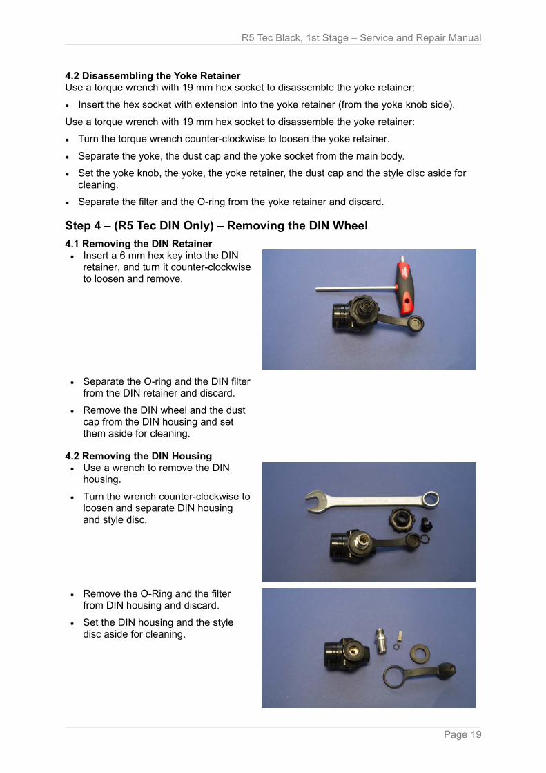
4.1 Removing the DIN Retainer● Insert a 6 mm hex key into the DIN
retainer, and turn it counter-clockwise to loosen and remove.
● Separate the O-ring and the DIN filter from the DIN retainer and discard.
● Remove the DIN wheel and the dust cap from the DIN housing and set them aside for cleaning.
4.2 Removing the DIN Housing● Use a wrench to remove the DIN
housing.
● Turn the wrench counter-clockwise to loosen and separate DIN housing and style disc.
● Remove the O-Ring and the filter from DIN housing and discard.
● Set the DIN housing and the style disc aside for cleaning.
Page 19
R5 Tec Black, 1st Stage – Service and Repair Manual
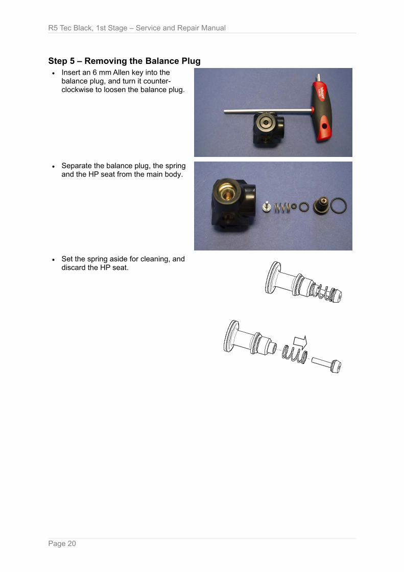
Step 5 – Removing the Balance Plug● Insert an 6 mm Allen key into the
balance plug, and turn it counter-clockwise to loosen the balance plug.
● Separate the balance plug, the spring and the HP seat from the main body.
● Set the spring aside for cleaning, and discard the HP seat.
Page 20
R5 Tec Black, 1st Stage – Service and Repair Manual
● Use O-ring pick tool to separate and discard the O-rings from the balance plug.
● Set the balance plug aside for cleaning.
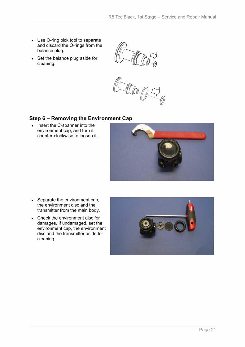
Step 6 – Removing the Environment Cap● Insert the C-spanner into the
environment cap, and turn it counter-clockwise to loosen it.
● Separate the environment cap, the environment disc and the transmitter from the main body.
● Check the environment disc for damages. If undamaged, set the environment cap, the environmentdisc and the transmitter aside for cleaning.
Page 21

R5 Tec Black, 1st Stage – Service and Repair Manual
Step 7 – Removing Diaphragm Clamping, Diaphragm and Lifter ● Insert a 6 mm Allen key into the
adjustment nut, and turn it counter-clockwise to remove the adjustment nut from the diaphragm clamping.
● Separate the main spring and the main spring washer from the main body.
● Insert the C-spanner into the diaphragm clamping and turn it counter-clockwise to loosen the clamping.
● Separate the spring seat from the main body and set it aside for cleaning.
● Remove the diaphragm washer and the diaphragm, and discard these parts.
● Separate the lifter from the main body, and set it aside for cleaning.
● Remove the holding tool from the main body, and set the main body aside for cleaning.
Page 22
R5 Tec Black, 1st Stage – Service and Repair Manual
Cleaning and Inspection
GeneralAll parts should be cleaned first in a warm detergent (not over 56 °C), consisting of mild soapand water. Use a soft nylon bristle brush to remove any excess or loose contamination.After this initial cleaning, rinse all parts thoroughly in clean fresh water and dry them with filtered low-pressure air (2 bar).
Then, metal parts should be cleaned in an ultrasonic cleaner using the appropriate ultrasonic cleaning solution (see table with lubricants and cleaners).
Be sure, all O-rings and other rubber or plastic parts are removed before cleaning in an ultrasonic cleaner or chemical bath. Cleaning solutions may damage these components.
If an ultrasonic cleaner is not available, metal parts can be cleaned by soaking them in a chemical bath of Chrome safe (see table with lubricants and cleaners) and agitating gently for 3-4 minutes. Metal parts can also be cleaned in a mild acetic solution (distilled white household vinegar) for 10-15 minutes.
WarningCleaning times in excess of those recommended may damage plated parts. Never clean parts for longer than specified by the manufacturer of the solution used.
Only parts made of brass, plated brass, and stainless steel should be immersed in chemical cleaning solutions.
CautionUse the proper hand and eye protection when handling chemical cleaning solutions.
After cleaning in any solution, thoroughly rinse parts with clean fresh water and dry them with filtered low-pressure air (2 bar).
Before beginning the reassembly, inspect all parts (new and reused), to ensure that each part is clean and free of any contamination, corrosion, or degradation.
All O-rings must be replaced during servicing. New O-rings should be inspected for contamination and/or imperfections.
LubricationSome O-Rings should be lightly dressed with a thin film of approved lubricant prior to installation (see table with lubricants and cleaners).
WarningRemember, that lubricated O-Rings tend to "attract" contamination. Therefore, you should only lubricate O-rings that are in contact with moving parts.
Do not use any petroleum based lubricants or products, or any aerosol silicone sprays on any part of Scubatech regulators. The petroleum base or propellant gas may attack or weaken plastic or rubber parts.
Page 23
R5 Tec Black, 1st Stage – Service and Repair Manual
ReplacementIn addition to the O-rings, the following parts must be routinely replaced during servicing:
● HP seat
● Diaphragm
● Conical filter - yoke retainer
● Conical filter - DIN connector
All O-rings and the above mentioned replacement parts are included in the service kit.
InspectionThe following parts should be closely inspected as stated below. Close inspection is best accomplished by using strong magnification under bright light.
● Main body:Inspect all cavities for nicks, scratches, pitting, or any defects in the plating. Pay particular attention to the sealing edge of the valve cone and the diaphragm seating shoulder.
● Diaphragm clamping:Inspect for signs of permanent corrosion, including pitting or cracks in the metal surface.
● Environment cap:Inspect for signs of permanent corrosion, including pitting or cracks in the metal surface.
● Main spring:Inspect for signs of permanent corrosion, including pitting or cracks in the metal surface.
● Balance spring:Inspect for signs of permanent corrosion, including pitting or cracks in the metal surface.
● Balance plug:inspect the interior sealing area and O-ring sealing groove for any nicks, scratches, pitting, or any defect of the chrome plating.
● Lifter:Inspect the interior cavity for any nicks, scratches, pitting.
● DIN or yoke retainer:Examine the condition of the threads and the O-ring sealing groove at the base for any signs of damage.
● DIN wheel:Examine the condition of the threads for any signs of damage.
Should any of the listed parts show any damage, they must be replaced with a new part.
Check all metal parts for excessive wear or corrosion.
Check all metal sealing surfaces, which make contact with O-rings for any signs of contamination and/or imperfections, that may cause leakage past the O-ring seal.
Examine all chrome plated surfaces for any evidence of peeling or flaking of the chrome plating.
Inspect all threads for galling, cross threading, or damage to the chrome plating.
Should any parts show damage or excessive wear, they must be replaced with new parts.
Page 24

R5 Tec Black, 1st Stage – Service and Repair Manual
About O2-Clean RegulatorsThe use of Scubatech regulators with up to 100 % oxygen as breathing gas requires thorough procedures for cleaning, de-greasing and assembly.
WarningOnly make a Scubatech regulator O2 clean, if there is a special O2 kit with Viton O-rings available for this particular regulator.
After cleaning the metal parts in the ultrasound bath, rinse them with distilled water and de-grease them with acetone. Always wear single-use medical gloves to handle acetone-cleaned metal parts in order to avoid finger prints.
Check de-greased metal parts with ultraviolet light for fingerprints.
Only use lubricants certified for pure oxygen with 300 bar (e. g. "Klüberalfa"). Lubricate only, where absolutely necessary.
AssemblyWarningUse only genuine Scubatech parts, subassemblies, and components when assembling any Scubatech product.
CautionDO NOT attempt to substitute a genuine Scubatech part with a part by another manufacturer, regardless of any similarity in shape, size, or appearance. Doing so may render the product unsafe, and could result in serious injury or death.
Step 1 – Adding New O-Rings to the Balance Plug● Place the two O-rings on the
balance plug.
● Use the O-ring pick tool with ball end to push the third (small) O-ring into the balance plug.
● Place the balance spring on the balance plug.
● Install the HP seat on the balance spring and set the sub-assembly aside.
Page 25

R5 Tec Black, 1st Stage – Service and Repair Manual
Step 2 – Installing O-Rings on all HP/LP Plugs and/or Hose Ends● Install the matching O-rings
(HP/LP) on all plugs and/or hoses used with the 1st stage.
Step 3 – Installing the Diaphragm Clamping● Insert the holding tool into the
main body. Make sure the thread is fully inserted into the main body.
● Assemble the lifter, the diaphragm and the diaphragm washer:Place the lifter in the main body and make sure the mushroom-shaped lifter head lies flat.
● Place the diaphragm in the under-cut groove of the main body.
● Place the diaphragm washer on the diaphragm and make sure, that its edge is fully inserted into the groove.
● Place the spring seat on the diaphragm.
● Assemble the Diaphragm Clamping:Screw the diaphragm clamping clockwise into the main body, untilit touches the diaphragm.
● Tighten the diaphragm clamping:Insert the C-spanner into the diaphragm clamping, and turn it clockwise, until diaphragm clamping and main body lie metal to metal (max. torque 14 Nm).
Page 26
R5 Tec Black, 1st Stage – Service and Repair Manual
Step 5 – Assembling the Main Spring● Slightly lubricate a spring washer
and place it on the spring seat.
● Place the main spring on the spring washer.
● Slightly lubricate a spring washer and place it on the main spring.
● Place the adjusting nut on the spring washer.
● Insert a 6 mm Allen key into the adjusting nut.
● Turn the adjusting nut clockwise approx. 3 turns in.
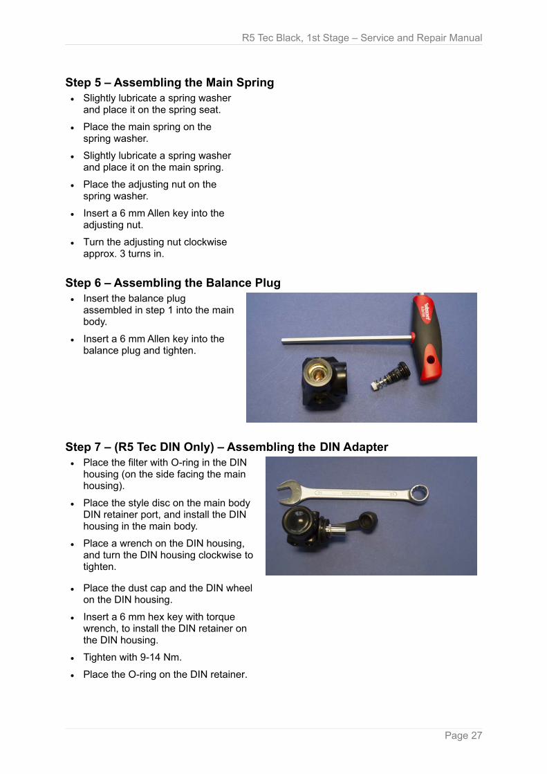
Step 6 – Assembling the Balance Plug● Insert the balance plug
assembled in step 1 into the main body.
● Insert a 6 mm Allen key into the balance plug and tighten.
Step 7 – (R5 Tec DIN Only) – Assembling the DIN Adapter● Place the filter with O-ring in the DIN
housing (on the side facing the main housing).
● Place the style disc on the main body DIN retainer port, and install the DIN housing in the main body.
● Place a wrench on the DIN housing, and turn the DIN housing clockwise to tighten.
● Place the dust cap and the DIN wheel on the DIN housing.
● Insert a 6 mm hex key with torque wrench, to install the DIN retainer on the DIN housing.
● Tighten with 9-14 Nm.
● Place the O-ring on the DIN retainer.
Page 27

R5 Tec Black, 1st Stage – Service and Repair Manual
Step 7 – (R5 Tec Yoke Only) – Assembling the Yoke● Place the filter and the O-ring in the yoke retainer.
● Put the style disc, the dust cap and the yoke on the adapter port, and screw the yoke retainer subassembly clockwise into the adapter port.
● Insert a 19 mm hex key with torque wrench and extension into the yoke retainer.
● Turn the torque wrench clockwise to tighten with 9-14 Nm.
● Install the yoke knob.
Step 8 – Finishing the Assembly and Pre-Setting● Prepare a SCUBA tank with pressurized air (at least 100 bar).
● Install the 1st stage on the tank (only finger-tight the yoke knob/DIN wheel).
● Open the tank valve to blow out all ports in the main body (this frees them from small chips, created during assembly).
● Install the HP/LP plugs in the main body, and tighten with 4 Nm.
● Preset the IP:Install the LP hose, a LP gauge, an adjusting tool and the 2nd stage on the 1st stage.
● Insert a 6 mm Allen key into the adjusting nut and slowly turn it clockwise.
● When turning the adjusting nut, put the other hand on the 2nd stage and keep purging the 2nd stage with every half-turn, until the IP reaches 8,5 – 9.0 bar.
● Purge the 2nd stage repeatedly and make sure, the IP gauge stops at 9.0 bar. After several purging cycles, the intermediate pressure may creep over 9.0 bar. But it must stop at max 9.4 bar and stay there after 5 minutes.
● Install the environment kit:Place the transmitter, the environment diaphragm and the environment cap on the 1st stage.
● Insert a C-spanner in the environment cap, and turn clockwise to tighten it with 14vNm.
Step 9 – Testing the Intermediate PressureCautionBefore testing the intermediate pressure, you need to connect the 1st stage to a fully assembled and properly adjusted second stage. This will provide a safety relief valve, should the intermediate pressure exceed 11-12 bar.
If a properly adjusted second stage is not available, be sure to open the bleed valve of the test gauge before pressurizing!
Failure to relieve intermediate pressure in excess of 28 bar may result in damage to the test gauge or LP hose, and/or to severe injuries.
Test the function of the environment kit:
● Push in deeply the environment disc of the pressurized 1st stage.
● Check, if the IP value on the gauge is increasing.
Page 28
R5 Tec Black, 1st Stage – Service and Repair Manual
Adjustment and TestingWith a stabilized IP, the IP working range for the R5 Tec is 8,5-9,5 bar. A higher or lower IP is outside the specifications and thus not acceptable.
In case of problems with the intermediate pressure, see the troubleshooting table.
TroubleshootingSYMPTOM CAUSE ACTION REQUIRED
Restricted airflow/high inhalation resistance throughout the entire system ("hard to breathe")
1. Tank valve not completely opened
2. Tank valve requires service3. Tank filter is contaminated4. Insufficient intermediate
pressure
1. Open valve, check fill pressure.2. Connect to a different tank3. Replace with new filter.4. See below under "Lower IP”.
External air leakage (immersion test) or hydrostatic diaphragm is abnormally deformed or damaged
1. Balance plug2. HP plug3. LP plug4. DIN/ YOKE connector loose5. Diaphragm clamping6. Environment disc7. Swivel cap
1. Replace one O-ring and tighten again. Check again. If this does not help, replace the next O-ring and so on.
2. Install a new diaphragm and make sure, the installation steps are followed closely.
3. Open the environment cap to check the environment disc for damages. If damaged, install a new one and tighten again.
4. Replace the O-Ring and tighten the balance plug again.
IP drift (creep) 1. HP seat damaged2. O-ring defective or scratches
in main body
1. Replace the damaged HP seat.2. Replace the O-ring and/or the HP
seat, and check the orifice edges of the main body for dents or scratches. If present, replace with a new main body.
Higher IP 1. Main spring supporting force too high
1. Turn the adjusting nut counter-clockwise to decrease the IP.
Lower IP 1. Spring force too little 1. Turn the adjusting nut clockwise to increase the IP.
Page 29

R5 Tec Black, 1st Stage – Service and Repair Manual
Appendix 1: Specifications
Water chamber protected against freezing (ICE)
Rotating head -
Quantity of LP/HP ports 4 / 2
Type Diaphragm
Maximum pressure 300 bar
Intermediate pressure (working) 9,0 bar
Maximum flow at 20 MPa 3823 l/min
Nitrox up to 40 %
Nitrox from 40 % to 100 % -
Weight 805 g
Material Maritime bronze
Page 30

Appendix 2: Service FormNoteYou may use the following Service form to document your service procedures for Scubatech regulators internally and for the customer.
Scubatech recommends to implement a proper filing system in order to have a transparent service documentation.
Be sure to observe your local/legal requirements regarding such documentation.

Service no.:
Regulator Service Form
General Information
Service start date: _______________________________________________
Regulator type: _______________________________________________
1st stage serial no.: _______________________________________________
2nd stage(s) no.: _______________________________________________
Service carried out by: _______________________________________________
Special customer orders:
Regulator on arrival
Regulator configuration: __________________________________________
Intermediate pressure: __________________________________________
Inhale resistance: __________________________________________
Exhale resistance: __________________________________________
Observations:
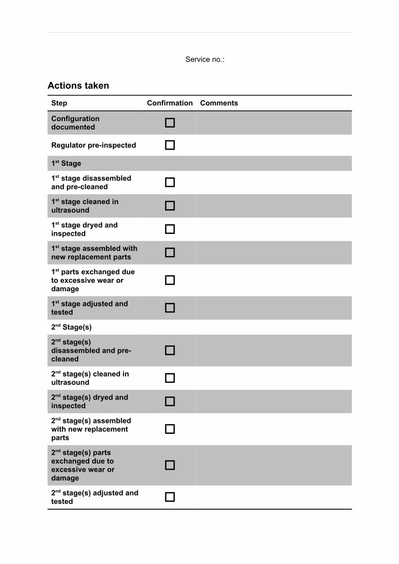
Service no.:
Actions taken
Step Confirmation Comments
Configuration documented
Regulator pre-inspected 1st Stage
1st stage disassembled and pre-cleaned 1st stage cleaned in ultrasound 1st stage dryed and inspected 1st stage assembled with new replacement parts 1st parts exchanged due to excessive wear or damage
1st stage adjusted and tested 2nd Stage(s)
2nd stage(s) disassembled and pre-cleaned
2nd stage(s) cleaned in ultrasound 2nd stage(s) dryed and inspected 2nd stage(s) assembled with new replacement parts
2nd stage(s) parts exchanged due to excessive wear or damage
2nd stage(s) adjusted and tested

Service no.:
Regulator After ServiceConfiguration of serviced regulator:
Same as on arrival
Changed __________________________________________
Intermediate pressure: __________________________________________
Inhale resistance: __________________________________________
Exhale resistance: __________________________________________
Service Result
Regulator fully operational
Regulator NOT operational
Comments
Service end date: _______________________________________________
Signature of service technician: _______________________________________________
Hand-over date: _______________________________________________
Customer signature: _______________________________________________