R39 SI: ULTRALOW-TEMPERATURE REFRIGERATION · refrigeration system in which multiple stages of...
12
39.1 CHAPTER 39 ULTRALOW-TEMPERATURE REFRIGERATION Autocascade Systems .............................................................. 39.1 Custom-Designed and Field-Erected Systems ........................ 39.2 Single-Refrigerant Systems ..................................................... 39.2 Cascade Systems ..................................................................... 39.3 Low-Temperature Materials ................................................... 39.6 Insulation ................................................................................ 39.9 Heat Transfer .......................................................................... 39.9 Secondary Coolants .............................................................. 39.11 LTRALOW-TEMPERATURE refrigeration is defined here Uas refrigeration in the temperature range of -50 to -100°C. What is considered low temperature for an application depends on the temperature range for that specific application. Low tem- peratures for air conditioning are around 0°C; for industrial refriger- ation, -35 to -50°C; and for cryogenics, approaching 0 K. Applications such as freeze-drying, as well as the pharmaceutical, chemical, and petroleum industries, use refrigeration in the temper- ature range designated low in this chapter. The -50 to -100°C temperature range is treated separately be- cause design and construction considerations for systems that operate in this range differ from those encountered in the two fields bracketing it, namely, industrial refrigeration and cryogen- ics. Designers and builders of cryogenic facilities are rarely active in the low-temperature refrigeration field. One major type of low- temperature system is the packaged type, which often serves such applications as environment chambers. The other major cate- gory is custom-designed and field-erected systems. Industrial refrigeration practitioners are the group most likely to be respon- sible for these systems, but they may deal with low-temperature systems only occasionally; the experience of a single organization does not accumulate rapidly. The objective of this chapter is to bring together available experience for those whose work does not require daily contact with low-temperature systems. The refrigeration cycles presented in this chapter may be used in both standard packaged and custom-designed systems. Cascade systems are emphasized, both autocascade (typical of the pack- aged units) and two-refrigerant cascade (encountered in custom- engineered low-temperature systems). AUTOCASCADE SYSTEMS An autocascade refrigeration system is a complete, self-contained refrigeration system in which multiple stages of cascade cooling effect occur simultaneously by means of vapor-liquid separation and adiabatic expansion of various refrigerants. Physical and thermody- namic features, along with a series of counterflow heat exchangers and an appropriate mixture of refrigerants, make it possible for the system to reach low temperature. Autocascade refrigeration systems offer many benefits, such as a low compression ratio and relatively high volumetric efficiency. However, system chemistry and heat exchangers are complex, refrigerant compositions are sensitive, and compressor displace- ment is large. Operational Characteristics Components of an autocascade refrigeration system typically include a vapor compressor, an external air- or water-cooled con- denser, a mixture of refrigerants with descending boiling points, and a series of insulated heat exchangers. Figure 1 is a schematic diagram of a simple system illustrating a single stage of autocascade effect. In this system, two refrigerants, which have significantly differ- ent boiling points, are compressed and circulated by one vapor com- pressor. Assume that one refrigerant is R-23 (normal boiling point, -82°C) and the second refrigerant is R-404a (normal boiling point, -46.7°C). Assume that ambient temperature is 25°C and that the condenser is 100% efficient. With properly sized components, this system should be able to achieve -60°C in the absorber while the compression ratio is main- tained at 5.1 to 1. As the refrigerant mixture is pumped through the main condenser and cooled to 25°C at the exit, compressor dis- charge pressure is maintained at 1524 kPa (gage). At this condition, virtually all R-404a is condensed at 35°C and then further chilled to subcooled liquid. Although R-23 molecules are present in both liq- uid and vapor phases, the R-23 is primarily vapor due to the large difference in the boiling points of the two refrigerants. A phase sep- arator located at the outlet of the condenser therefore collects the liquid by gravitational effect, and the R-23-rich vapor is removed from the outlet of the phase separator to the heat exchanger. At the bottom of the phase separator, an expansion device adia- batically expands the collected R-404a-rich liquid such that the outlet of the device produces a low temperature of -19°C at 220 kPa (gage) (Weng 1995). This cold stream is immediately sent back to the heat exchanger in a counterflow pattern such that the R-23-rich vapor is condensed to liquid at -18.5°C and 1524 kPa (gage). The R-23-rich liquid is then adiabatically expanded by a second expansion device to -60°C. As it absorbs an appropriate amount of heat in the absorber, the R-23 mixes with the expanded R-404a and evaporates in the heat exchanger, providing a cold source for condensing R-23 on the high-pressure side of the heat The preparation of this chapter is assigned to TC 10.4, Ultralow-Tempera- ture Systems and Cryogenics. Fig. 1 Simple Autocascade Refrigeration System 1. Compressor 2. Oil separator 3. Condenser 4. Filter drier 5. Phase separator 6. Vapor tube to second condenser 7. Heat exchanger (evaporator of first refrigerant, cooling second refrigerant) 8. First refrigerant liquid line to metering device 9. First refrigerant metering device feeding heat exchanger, cooling second refrigerant 10. Second refrigerant metering device 11. Evaporator 12. Suction lines to compressor Copyright © 2002 ASHRAE
Transcript of R39 SI: ULTRALOW-TEMPERATURE REFRIGERATION · refrigeration system in which multiple stages of...
Copyright © 2002 ASHRAE
CHAPTER 39
ULTRALOW-TEMPERATURE REFRIGERATION
Autocascade Systems .............................................................. 39.1Custom-Designed and Field-Erected Systems ........................ 39.2Single-Refrigerant Systems ..................................................... 39.2Cascade Systems ..................................................................... 39.339
Low-Temperature Materials ................................................... 39.6Insulation ................................................................................ 39.9Heat Transfer .......................................................................... 39.9Secondary Coolants .............................................................. 39.11
LTRALOW-TEMPERATURE refrigeration is defined here Fig. 1 Simple Autocascade Refrigeration System
Uas refrigeration in the temperature range of −50 to −100°C.What is considered low temperature for an application depends onthe temperature range for that specific application. Low tem-peratures for air conditioning are around 0°C; for industrial refriger-ation, −35 to −50°C; and for cryogenics, approaching 0 K.Applications such as freeze-drying, as well as the pharmaceutical,chemical, and petroleum industries, use refrigeration in the temper-ature range designated low in this chapter.The −50 to −100°C temperature range is treated separately be-cause design and construction considerations for systems thatoperate in this range differ from those encountered in the twofields bracketing it, namely, industrial refrigeration and cryogen-ics. Designers and builders of cryogenic facilities are rarely activein the low-temperature refrigeration field. One major type of low-temperature system is the packaged type, which often servessuch applications as environment chambers. The other major cate-gory is custom-designed and field-erected systems. Industrialrefrigeration practitioners are the group most likely to be respon-sible for these systems, but they may deal with low-temperaturesystems only occasionally; the experience of a single organizationdoes not accumulate rapidly. The objective of this chapter is tobring together available experience for those whose work does notrequire daily contact with low-temperature systems.
The refrigeration cycles presented in this chapter may be usedin both standard packaged and custom-designed systems. Cascadesystems are emphasized, both autocascade (typical of the pack-aged units) and two-refrigerant cascade (encountered in custom-engineered low-temperature systems).
AUTOCASCADE SYSTEMS
An autocascade refrigeration system is a complete, self-containedrefrigeration system in which multiple stages of cascade coolingeffect occur simultaneously by means of vapor-liquid separation andadiabatic expansion of various refrigerants. Physical and thermody-namic features, along with a series of counterflow heat exchangersand an appropriate mixture of refrigerants, make it possible for thesystem to reach low temperature.
Autocascade refrigeration systems offer many benefits, such as alow compression ratio and relatively high volumetric efficiency.However, system chemistry and heat exchangers are complex,refrigerant compositions are sensitive, and compressor displace-ment is large.
Operational CharacteristicsComponents of an autocascade refrigeration system typically
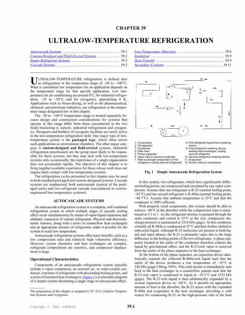
include a vapor compressor, an external air- or water-cooled con-denser, a mixture of refrigerants with descending boiling points, anda series of insulated heat exchangers. Figure 1 is a schematic diagramof a simple system illustrating a single stage of autocascade effect.
The preparation of this chapter is assigned to TC 10.4, Ultralow-Tempera-ture Systems and Cryogenics.
In this system, two refrigerants, which have significantly differ-ent boiling points, are compressed and circulated by one vapor com-pressor. Assume that one refrigerant is R-23 (normal boiling point,−82°C) and the second refrigerant is R-404a (normal boiling point,−46.7°C). Assume that ambient temperature is 25°C and that thecondenser is 100% efficient.
With properly sized components, this system should be able toachieve −60°C in the absorber while the compression ratio is main-tained at 5.1 to 1. As the refrigerant mixture is pumped through themain condenser and cooled to 25°C at the exit, compressor dis-charge pressure is maintained at 1524 kPa (gage). At this condition,virtually all R-404a is condensed at 35°C and then further chilled tosubcooled liquid. Although R-23 molecules are present in both liq-uid and vapor phases, the R-23 is primarily vapor due to the largedifference in the boiling points of the two refrigerants. A phase sep-arator located at the outlet of the condenser therefore collects theliquid by gravitational effect, and the R-23-rich vapor is removedfrom the outlet of the phase separator to the heat exchanger.
At the bottom of the phase separator, an expansion device adia-batically expands the collected R-404a-rich liquid such that theoutlet of the device produces a low temperature of −19°C at220 kPa (gage) (Weng 1995). This cold stream is immediately sentback to the heat exchanger in a counterflow pattern such that theR-23-rich vapor is condensed to liquid at −18.5°C and 1524 kPa(gage). The R-23-rich liquid is then adiabatically expanded by asecond expansion device to −60°C. As it absorbs an appropriateamount of heat in the absorber, the R-23 mixes with the expandedR-404a and evaporates in the heat exchanger, providing a coldsource for condensing R-23 on the high-pressure side of the heat
Fig. 1 Simple Autocascade Refrigeration System
1. Compressor2. Oil separator3. Condenser4. Filter drier5. Phase separator6. Vapor tube to second condenser7. Heat exchanger (evaporator of first
refrigerant, cooling second refrigerant)
8. First refrigerant liquid line to metering device
9. First refrigerant metering device feeding heat exchanger, cooling second refrigerant
10. Second refrigerant metering device11. Evaporator12. Suction lines to compressor
.
1
39.2 2002 ASHRAE Refrigeration Handbook (SI)
exchanger. Leaving the heat exchanger at superheated conditions, plant using a single refrigerant or a two-circuit cascade system using
Fig. 2 Four-Stage Autocascade System
Fig. 2 Four-Stage Autocascade System
the vapor mixture then returns to the suction of the compressor forthe next cycle.
As can be seen from this simple example, the autocascade effectderives from a short cycle of the refrigerant circuit within the sys-tem that performs only internal work to condense the lower boilingpoint refrigerant.
The concept of the single-stage cycle can be extended to multiplestages. Figure 2 shows the flow diagram of a four-stage system. Thecondensation and subsequent expansion of one refrigerant providesthe cooling necessary to condense the next refrigerant in the heatexchanger downstream. This process continues until the last refrig-erant with the lowest boiling point is expanded to achieve extremelylow temperature.
Design ConsiderationsCompressor Capacity. As can be seen from Figures 1 and 2, a
significant amount of compressor work is used for internal evapo-rating and condensing of refrigerants. The final gain of the system istherefore relatively small. Compressor capacity must be sufficientto produce an appropriate amount of final refrigerating effect.
Heat Exchanger Sizing. Because there is a significant amountof refrigerant vapor in each stage of the heat exchanger, the overallheat-transfer coefficients on both the evaporating side and the con-densing side are rather small compared to those of pure componentsat phase-changing conditions. Therefore, generous heat-transferarea should be provided for energy exchange between refrigerantson the high- and low-pressure sides.
Expansion Devices. Each expansion device is sized to providesufficient refrigerating effect for the adjacent downstream heatexchanger.
Compressor Lubrication. General guidelines for lubrication ofrefrigeration systems should be adopted.
CUSTOM-DESIGNED AND FIELD-ERECTED SYSTEMS
If the refrigeration assignment is to maintain a space at a low tem-perature to store a modest quantity of product in a chest or cabinet,the packaged low-temperature system is probably the best choice.Prefabricated walk-in environmental chambers are also practicalsolutions when they can accommodate space needs. When therequired refrigeration capacity exceeds that of packaged systems, orwhen a fluid must be chilled, a custom-engineered system should beconsidered.
The refrigeration requirement may be to chill a certain flow rateof a given fluid from one temperature to another. Part of the designprocess is to choose the type of system, which may be a multistage
a high-pressure refrigerant for the low-temperature circuit. Thecompressor(s) and condenser(s) must be selected, and the evapora-tor and interstage heat exchanger (in the case of the cascade system)must be either selected or custom-designed.
The design process includes selection of (1) metal for piping andvessels and (2) insulating material and method of application. Theproduct to be refrigerated may actually pass through the evaporator,but in many cases a secondary coolant transfers heat from the finalproduct to the evaporator. Brines and antifreezes that perform satis-factorily at higher temperatures may not be suitable at low temper-atures. Compressors are subjected to unusual demands whenoperating at low temperatures, and because they must be lubricated,oil selection and handling must be addressed.
SINGLE-REFRIGERANT SYSTEMS
Single-refrigerant systems are contrasted with the cascade system,which consists of two separate but thermally connected refrigerantcircuits, each with a different refrigerant (Stoecker and Jones 1982).
In the industrial refrigeration sector, the traditional refrigerantshave been R-22 and ammonia (R-717). Because R-22 will ulti-mately be phased out, various hydrofluorocarbon (HFC) refriger-ants and blends are proposed as replacements. Two that might beconsidered are R-507 and R-404a.
Two-Stage SystemsIn systems where the evaporator operates below about −20°C,
two-stage or compound systems are widely used. These systems areexplained in Chapter 3 of this volume and in Chapter 1 of theASHRAE Handbook—Fundamentals. Advantages of two-stagecompound systems that become particularly prominent when theevaporator operates at low temperature include
• Improved energy efficiency due to the removal of flash gas at theintermediate pressure and desuperheating of the discharge gasfrom the low-stage compressor before it enters the high-stagecompressor.
• Improved energy efficiency because the two-stage compressorsare more efficient operating against discharge-to-suction pressureratios that are lower than for a single-stage compressor.
• Avoidance of high discharge temperatures typical of single-stagecompression. This is important in reciprocating compressors butof less concern with oil-injected screw compressors.
• Possibility of a lower flow rate of liquid refrigerant to the evapo-rator because the liquid is at the saturation temperature of theintermediate pressure rather than the condensing pressure, as istrue of single-stage operation.

Ultralow-Temperature Refrigeration 39.3
Refrigerant and Compressor Selection
The compound, two-stage (or even three-stage) system is anobvious possibility for low-temperature applications. However, atvery low temperatures, certain limitations of the refrigerant itselfappear. These limitations include the freezing point, the pressureratios required of the compressors, and the volumetric flow at thesuction of the low-stage compressor per unit refrigeration capacity.Table 1 shows some key values for four candidate refrigerants, illus-trating some of the concerns that arise when considering refriger-ants that are widely applied in industrial refrigeration systems.Refrigerants not included in Table 1 are hydrocarbons (HCs), whichare candidates particularly in the petroleum and petrochemicalindustry, where the entire plant is geared toward working with flam-mable gases.
The first factor shown in Table 1 is the freezing point. It is not alimitation for the halocarbon refrigerants, but ammonia freezes at −78°C, so its use must be restricted to temperatures safely above thattemperature.
The next data shown are pressure ratios the compressors mustoperate against in two-stage systems. A condensing temperature of35°C is assumed, with the intermediate pressure being the geomet-ric mean of the condensing and evaporating pressures. Many low-temperature systems may be small enough that a reciprocating com-pressor would be favorable, but the limiting pressure ratio withreciprocating compressors is usually about 8, a value chosen to limitthe discharge temperature. An evaporating temperature of −70°C isabout the lowest permissible for systems using reciprocating com-pressors. For evaporating temperatures lower than −70°C, a three-stage system should be considered. An alternative to the reciprocat-ing compressor is the screw compressor, which operates with lowerdischarge temperatures because it is oil flooded. The screw com-pressor can therefore operate against larger pressure ratios than thereciprocating compressor; in larger systems, it is the favored com-pressor type.
The third characteristic shown in Table 1 is the required volu-metric pumping capacity of the compressor, measured at the com-pressor suction. This value is an indicator of the physical size of thecompressor; the values become huge at the −90°C evaporating tem-perature.
Some conclusions from Table 1 are
• A single-refrigerant, two-stage system can adequately serve aplant in the higher-temperature portion of the range consideredhere, but it becomes impractical in the lower-temperature portion.
• Ammonia, which has many favorable properties for industrialrefrigeration, has little appeal for low-temperature refrigerationbecause of its relatively high freezing point and pressure ratios.
Special Multistage Systems Special high-efficiency operations to recover volatile com-
pounds such as hydrocarbons use the reverse Brayton cycle. Thisconsists of one or two conventional compressor refrigeration cycleswith the lowest stage ranging from −60 to −100°C. This final stage
Table 1 Low-Temperature Characteristics of Several Refrigerants at Three Evaporating Temperatures
Refrigerant
Freezing Point
Pressure Ratio withTwo-Stage System
Volumetric Flow of Refrigerant, L/s per kW
Evaporating Temp. Evaporating Temp.
−50°C −70°C −90°C −50°C −70°C −90°C
R-22 −160°C 4.6 8.14 17.9 1.57 4.81 19.8
R-507 <−100°C 4.4 7.8 16.1 1.29 4.08 17.5
R-717 −77.8°C 5.75 11.1 25.4 2.05 7.24 —
R-404a <−100°C 4.36 7.58 15.2 1.34 4.13 16.75
is achieved by using a turbo compressor/expander and enables thecollection of liquefied hydrocarbons (Emhö 1997; Jain and Ennek-ing 1995; Enneking and Priebe 1993).
CASCADE SYSTEMS
The cascade system, illustrated in Figure 3, confronts some ofthe problems of single-refrigerant systems. The system consists oftwo separate circuits, each using a refrigerant appropriate for itstemperature range. The two circuits are thermally connected by thecascade condenser, which is the condenser of the low-temperaturecircuit and the evaporator of the high-temperature circuit. Refriger-ants typically chosen for the high-temperature circuit include R-22,ammonia, R-507, R-404a, and so forth. For the low-temperature cir-cuit, a high-pressure refrigerant with a high vapor density (even atlow temperatures) is chosen. For many years, R-503, an azeotropicmixture of R-13 and R-23, has been a popular choice, but R-503 isno longer available because R-13 is an ozone-depleting chlorofluo-rocarbon (CFC). R-23 could be and has been used alone, butR-508b, an azeotrope of R-23 and R-116, has superior properties.R-508b is discussed further in the section on Refrigerants for Low-Temperature Circuit.
The cascade system possesses some of the thermal advantages oftwo-stage, single-refrigerant systems in that it approximates theflash gas removal process and also permits each compressor to takea share of the total pressure ratio between the low-temperature evap-orator and the condenser. The cascade system has the thermal dis-advantage of needing to provide an additional temperature lift in thecascade condenser because the condensing temperature of the low-temperature refrigerant is higher than the evaporating temperatureof the high-temperature refrigerant. There is an optimum operatingtemperature of the cascade condenser for minimum total powerrequirement, just as there is an optimum intermediate pressure intwo-stage, single-refrigerant systems.
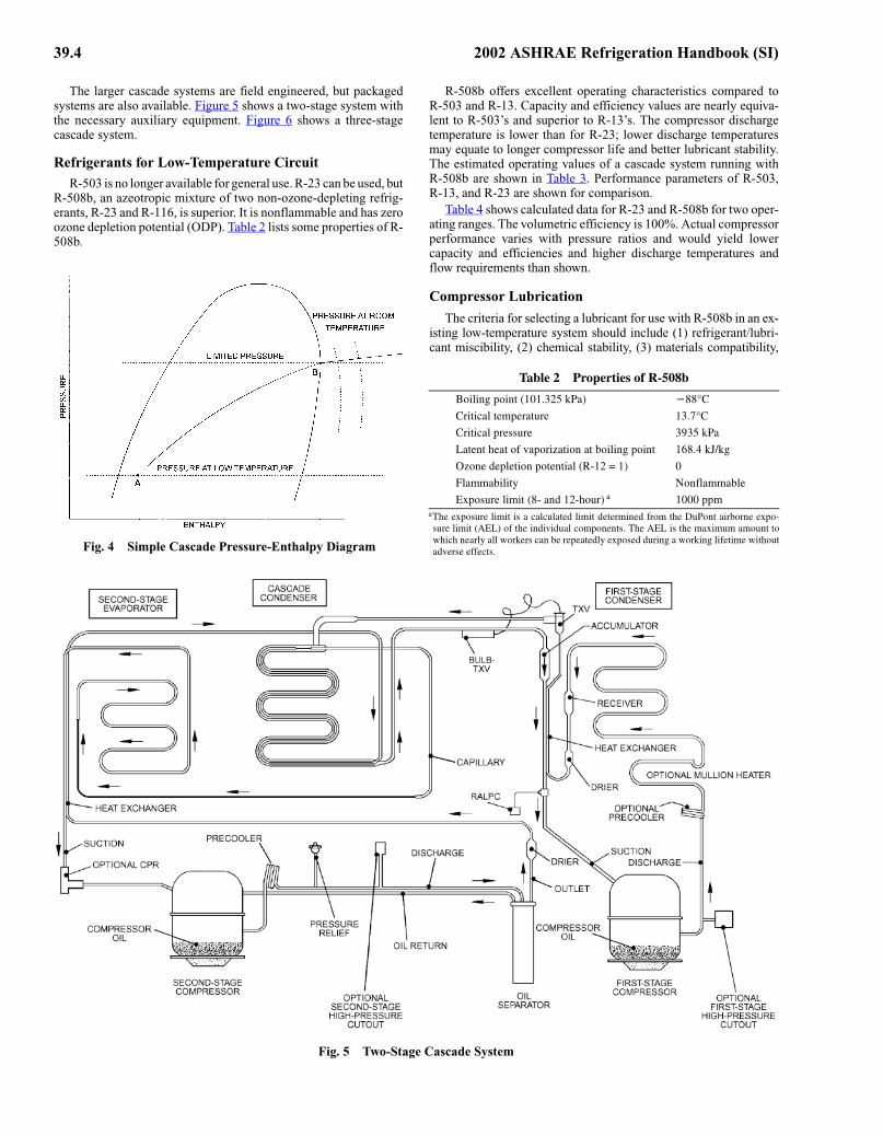
Figure 3 shows a fade-out vessel, which limits the pressure inthe low-temperature circuit when the system shuts down. At roomtemperature, the pressure of R-23 or R-508b in the system wouldexceed 4000 kPa if liquid were present. The entire low-temperaturesystem must be able to accommodate this pressure. The processtaking place in the fade-out vessel is at constant volume, as shownon the pressure-enthalpy diagram of Figure 4. When the systemoperates at low temperature, the refrigerant in the system is a mix-ture of liquid and vapor, indicated by point A. When the systemshuts down, the refrigerant begins to warm and follows the con-stant-volume line, with the pressure increasing according to the sat-uration curve. When the saturated vapor line is reached at point B,further increases in temperature result in only slight increases inpressure because the refrigerant is superheated vapor.
Fig. 3 Simple Cascade System
Fig. 3 Simple Cascade System
39.4 2002 ASHRAE Refrigeration Handbook (SI)
The larger cascade systems are field engineered, but packagedsystems are also available. Figure 5 shows a two-stage system withthe necessary auxiliary equipment. Figure 6 shows a three-stagecascade system.
Refrigerants for Low-Temperature CircuitR-503 is no longer available for general use. R-23 can be used, but
R-508b, an azeotropic mixture of two non-ozone-depleting refrig-erants, R-23 and R-116, is superior. It is nonflammable and has zeroozone depletion potential (ODP). Table 2 lists some properties of R-508b.Fig. 4 Simple Cascade Pressure-Enthalpy Diagram
Fig. 4 Simple Cascade Pressure-Enthalpy Diagram
R-508b offers excellent operating characteristics compared toR-503 and R-13. Capacity and efficiency values are nearly equiva-lent to R-503’s and superior to R-13’s. The compressor dischargetemperature is lower than for R-23; lower discharge temperaturesmay equate to longer compressor life and better lubricant stability.The estimated operating values of a cascade system running withR-508b are shown in Table 3. Performance parameters of R-503,R-13, and R-23 are shown for comparison.
Table 4 shows calculated data for R-23 and R-508b for two oper-ating ranges. The volumetric efficiency is 100%. Actual compressorperformance varies with pressure ratios and would yield lowercapacity and efficiencies and higher discharge temperatures andflow requirements than shown.
Compressor Lubrication
The criteria for selecting a lubricant for use with R-508b in an ex-isting low-temperature system should include (1) refrigerant/lubri-cant miscibility, (2) chemical stability, (3) materials compatibility,
Table 2 Properties of R-508b
_çáäáåÖ=éçáåí=ENMNKPOR=âm~F −UUø`
`êáíáÅ~ä=íÉãéÉê~íìêÉ= NPKTø`
`êáíáÅ~ä=éêÉëëìêÉ PVPR=âm~
i~íÉåí=ÜÉ~í=çÑ=î~éçêáò~íáçå=~í=ÄçáäáåÖ=éçáåí NSUKQ=âgLâÖ
lòçåÉ=ÇÉéäÉíáçå=éçíÉåíá~ä=EoJNO=Z=NF M
cä~ãã~Äáäáíó kçåÑä~ãã~ÄäÉ
bñéçëìêÉ=äáãáí=EUJ=~åÇ=NOJÜçìêF ~ NMMM=ééã~qÜÉ=ÉñéçëìêÉ=äáãáí=áë=~=Å~äÅìä~íÉÇ=äáãáí=ÇÉíÉêãáåÉÇ=Ñêçã=íÜÉ=aìmçåí=~áêÄçêåÉ=ÉñéçJ
ëìêÉ=äáãáí=E^biF=çÑ=íÜÉ=áåÇáîáÇì~ä=ÅçãéçåÉåíëK=qÜÉ=^bi=áë=íÜÉ=ã~ñáãìã=~ãçìåí=íç
ïÜáÅÜ=åÉ~êäó=~ää=ïçêâÉêë=Å~å=ÄÉ=êÉéÉ~íÉÇäó=ÉñéçëÉÇ=ÇìêáåÖ=~=ïçêâáåÖ=äáÑÉíáãÉ=ïáíÜçìí
~ÇîÉêëÉ=ÉÑÑÉÅíëK
Fig. 5 Two-Stage Cascade System
Fig. 5 Two-Stage Cascade System

Ultralow-Temperature Refrigeration 39.5
and (4) refrigeration system design. Original equipment manufactur-ers and compressor suppliers should be consulted.
It has been long-standing practice in the low-temperature indus-try to use additives to enhance system performance, and this prac-tice may be applied to R-508b. The miscibility of R-508b withcertain polyol esters (POEs) is slightly better than the limited mis-cibility of R-13 and R-503 with mineral oil and alkylbenzene, whichhelps oil circulation at the low evaporator temperatures. Even with
Table 3 Theoretical Performance of a Cascade System Using R-13, R-503, R-23, or R-508b
R-503 R-13 R-23 R-508b
`~é~Åáíó=EoJRMP=Z=NMMF NMM TN TQ VU
bÑÑáÅáÉåÅó=EoJRMP=Z=NMMF NMM NMR VR NMP
aáëÅÜ~êÖÉ=éêÉëëìêÉI=âm~ VVV TNT UQU NMNP
pìÅíáçå=éêÉëëìêÉI=âm~ NNM UP VM NNM
aáëÅÜ~êÖÉ=íÉãéÉê~íìêÉI=ø` NMT VO NPU UT
kçíÉW=léÉê~íáåÖ=ÅçåÇáíáçåë=~êÉ=−UQKQø`=Éî~éçê~íçêI=−PRø`=ÅçåÇÉåëÉêX=RKS=h=ëìÄÅççäJ
áåÖX=−NTKUø`=ëìÅíáçå=íÉãéÉê~íìêÉX=TMB=áëÉåíêçéáÅ=ÅçãéêÉëëáçå=ÉÑÑáÅáÉåÅóI=QB=îçäìJ
ãÉíêáÅ=ÅäÉ~ê~åÅÉK
Table 4 Theoretical Compressor Performance Data for Two Different Evaporating Temperatures
Refrigerant
EvaporatingTemperature,
°CPressure
Ratio
DischargeTemperature,
°C
Volumetric Flow,
L/s per kW
oJOP −UM TKQV RU NKNM
oJRMUÄ −UM SKRN PO MKUSS
oJOP −NMM OSKUU TO PKUR
oJRMUÄ −NMM ONKUU PV OKVQ
_~ëáëW=−PRø`=ÅçåÇÉåëáåÖ=íÉãéÉê~íìêÉX=ÅçãéêÉëëçê=ÉÑÑáÅáÉåÅó=çÑ=TMBX=îçäìãÉíêáÅ=ÉÑÑáJ
ÅáÉåÅó=çÑ=NMMBX=NM=h=ëìÄÅççäáåÖI=~åÇ=RM=h=ëìÅíáçå=ëìéÉêÜÉ~íK
the increased miscibility, additives may enhance performance. Cer-tain POE oils designed for use in very low temperature systems havebeen used successfully with R-508b in equipment retrofits. Com-pressor manufacturers and suppliers should be consulted before afinal decision on the lubricants and any additives is made.
CompressorsLarger cascade systems typically use standard, positive-
displacement compressors in the dual refrigeration system. Theevaporator of the higher temperature refrigerant system serves asthe condenser for the lower temperature refrigerant system. Thispermits rather normal application of the compressors on both sys-tems in relation to the pressures, compression ratios, and oil anddischarge temperatures within the compressors. However, severalvery important items must be considered for both the high and lowsides of the cascade system in order to avoid operational problems.Commercially available compressors must be analyzed for bothsides of the cascade system to determine the best combination for asuitable intermediate high-side evaporator/low-side condenser andminimum (or economical) system power usage.
High-Temperature Circuit. The higher temperature system isgenerally a single- or two-stage system using a commercial refrig-erant (R-134a, R-22, R-404a, or R-717); evaporating temperature isapproximately −23 to −45°C, and condensing is at normal ambientconditions. Commercially available reciprocating and screw com-pressors are suitable for this duty. If the compressor evaporatingtemperature is below −45°C, it becomes necessary to provide asuction-line heat exchanger to superheat the compressor suction gasto at least −43°C to avoid the low-temperature metal brittlenessassociated with lower temperatures at the compressor suction valveand body. Suction piping materials and the evaporator/condenser(evaporator side) must also be suitable for these low temperaturesper American Society of Mechanical Engineers (ASME) coderequirements.
Fig. 6 Three-Stage Cascade System
Fig. 6 Three-Stage Cascade System

39.6 2002 ASHRAE Refrigeration Handbook (SI)
The lubricant for the higher temperature system must be compat-ible with the refrigerant employed and suitable for the type of sys-tem, considering oil carryover and return from the evaporator andthe low-temperature conditions within the evaporator.
Low-Temperature Circuit. The compressor for this duty mayalso be a standard refrigeration compressor, provided that the com-pressor suction gas is superheated to at least −43°C to avoid low-temperature metal brittleness. Operation is typically well withinstandard pressure, oil temperature, and discharge temperature lim-its. The refrigerant is usually R-23 or R-508b. Because the temper-atures in the low side are below −45°C, all piping, valves, andvessels must be of materials in compliance with the ASME codespertaining to these temperatures.
It may be difficult to obtain compressor rating data for low-temperature applications with these refrigerants because fewactual test data are available, and the manufacturer may be reluc-tant to be specific. Therefore, the low side should not be designedtoo close to the required specification. A good practice is to calcu-late the actual volumetric flow rate to be handled by the compres-sor (at the expected superheat) to be certain that it can perform asrequired.
The capacity loss from the high superheat is more than recouped(for a net capacity gain) from the liquid subcooling obtained by thesuction-line heat exchanger. In rare cases, it may be necessary toinject a small quantity of hot gas into the suction to ensure maxi-mum suction temperature.
The lubricant selected for the low side of the cascade must becompatible with the specific refrigerant employed and also suitablefor the low temperatures expected in the evaporator. It is importantthat adequate coalescing oil separation (5 ppm) is provided to min-imize oil carryover from the compressor to the evaporator.
In direct-expansion evaporators, any oil is forced through thetubes, but the velocity in the return lines must be high enough tokeep this small amount of oil moving back to the compressor. If thesystem has capacity control, then multiple suction risers or alterna-tive design procedures may be required to prevent oil logging inthe evaporator and ensure oil return. At these ultralow tempera-tures, it is imperative to select a lubricant that remains fluid anddoes not plate out on the evaporator surfaces, where it can foul heattransfer.
Choice of Metal for Piping and VesselsThe usual construction metal for use with thermal fluids is car-
bon steel. However, at temperatures below −29°C, carbon steelshould not be used due to its loss of ductility. The designer shouldconsider the use of 304 or 316 stainless steel because of their goodlow-temperature ductility. Another alternative is to use carbon steelthat has been manufactured specifically to retain good ductility atlow temperatures (Dow Corning USA 1993). For example,
Carbon steel Down to −29°CSA - 333 - GR1 −29 to −46°CSA - 333 - GR7 −46 to −73°CSA - 333 - GR3 −59 to −101°CSA - 333 - GR6 To −46°C
LOW-TEMPERATURE MATERIALS
Choosing material for a specific low-temperature use is often acompromise involving several factors:
• Cost• Stress level at which the product will operate• Manufacturing alternatives• Operating temperature• Ability to weld and stress-relieve welded joints• Possibility of excessive moisture and corrosion
• Thermal expansion and modulus of elasticity characteristics for bolting and connection of dissimilar materials
• Thermal conductivity and resistance to thermal shock
Effect of Low Temperature on Materials. When the piping andvessels are to contain refrigerant at low temperature, special mate-rials must usually be chosen because of the effect of low tem-perature on material properties. Chemical interactions between therefrigerant and containment material must also be considered.Mechanical and physical properties, fabricability, and availabilityare some of the important factors to consider in selecting a materialfor low-temperature applications. Few generalizations can be made,except that decreased temperature increases hardness, strength, andmodulus of elasticity. The effect of low temperatures on ductilityand toughness can vary considerably between materials. With adecrease in temperature, some metals show an increase in ductility;others show an increase to some limiting low temperature, followedby a decrease at lower temperatures. Still other metals show adecrease in toughness and ductility as the temperature is decreasedbelow room temperature.
The effect of temperature reduction on polymers depends on thetype of polymer. Thermoplastic polymers, which soften whenheated above their glass transition temperature Tg, become progres-sively stiffer and finally brittle at low temperatures. Thermosettingplastics, which are highly cross-linked and do not soften whenheated, are brittle at ambient temperatures and remain so at lowertemperatures. Elastomers (rubbers) are lightly cross-linked andstiffen like thermoplastics as the temperature is lowered, becomingfully brittle at very low temperatures.
Although polymers become brittle and may crack at low temper-atures, their unique combination of properties—excellent thermaland electrical insulation capability, low density, low heat capacity,and nonmagnetic character—make them attractive for a variety oflower-temperature applications. At extremely low temperatures, allplastic materials are very brittle and have low thermal conductivityand low strength relative to metals and composites, so selection anduse must be carefully evaluated.
Fiber composite materials have gained widespread use at lowtemperatures, despite their incorporation of components that areoften by themselves brittle. A factor that must be considered in theuse of composites is the possibility of anisotropic behavior, inwhich they exhibit properties with different values when measuredalong axes in different directions. Composites with aligned fibersare highly anisotropic.
MetalsThe relation of tensile strength to temperature for metals com-
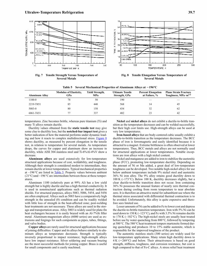
monly used for structural applications at low temperatures is shown inFigure 7 (Askeland 1994). The slopes of the curves indicate that theincrease in strength with decrease in temperature varies among thedifferent metals. However, tensile strength is not the best criterion fordetermining the suitability of a material for low-temperature servicebecause most failures result from a loss of ductility.
Lower temperatures can have a dramatic effect on the ductilityof metal; the effect depends to a large extent on crystal structure.Metals and alloys that are face-centered cubic (FCC) and ductile atambient temperatures remain ductile at low temperatures. Metals inthis category include aluminum, copper, copper-nickel alloys,nickel, and austenitic stainless steels. Metals and alloys that arebody-centered cubic (BCC), such as pure iron, carbon steel, andmany alloy steels, become brittle at low temperatures. Many BCCmetals and alloys exhibit a ductile-to-brittle transition at lower tem-peratures (see 1020 steel in Figure 8). This loss of ductility comesfrom a decrease in the number of operating slip systems, whichaccommodate dislocation motion. Hexagonal close-packed (HCP)metals and alloys occupy an intermediate place between FCC andBCC materials and may remain ductile or become brittle at low
Ultralow-Temperature Refrigeration 39.7
Table 5 Several Mechanical Properties of Aluminum Alloys at −196°C
Aluminum AlloyModulus of Elasticity,
GPaYield Strength,
MPaUltimate Tensile Strength, GPa
Percent Elongationat Failure, %
Plane Strain Fracture Toughness, MPa ·m1/2
1100-0 78 50 190 — —
2219-T851 85 440 568 14 45
5083-0 80 158 434 32 62
6061-T651 77 337 402 23 42
Fig. 7 Tensile Strength Versus Temperature ofSeveral Metals
Fig. 7 Tensile Strength Versus Temperature ofSeveral Metals
Fig. 8 Tensile Elongation Versus Temperature ofSeveral Metals
Fig. 8 Tensile Elongation Versus Temperature ofSeveral Metals
temperatures. Zinc becomes brittle, whereas pure titanium (Ti) andmany Ti alloys remain ductile.
Ductility values obtained from the static tensile test may givesome clue to ductility loss, but the notched-bar impact test gives abetter indication of how the material performs under dynamic load-ing and how it reacts to complex multidirectional stress. Figure 8shows ductility, as measured by percent elongation in the tensiletest, in relation to temperature for several metals. As temperaturedrops, the curves for copper and aluminum show an increase inductility, while AISI 304 stainless steel and Ti-6%Al-4%V show adecrease.
Aluminum alloys are used extensively for low-temperaturestructural applications because of cost, weldability, and toughness.Although their strength is considered modest to intermediate, theyremain ductile at lower temperatures. Typical mechanical propertiesat −196°C are listed in Table 5. Property values between ambient(21°C) and −196°C are intermediate between those at these temper-atures.
Aluminum 1100 (relatively pure at 99% Al) has a low yieldstrength but is highly ductile and has a high thermal conductivity. Itis used in nonstructural applications such as thermal radiationshields. For structural purposes, alloys 5083, 5086, 5454, and 5456are often employed. Alloys such as 5083 have a comparatively highstrength in the annealed (0) condition and can be readily weldedwith little loss of strength in the heat-affected zone; post-weldingheat treatments are not necessary. These alloys are used in the stor-age and transportation areas. Alloy 3003 is widely used for plate-finheat exchangers because it is easily brazed with an Al-7%Si fillermetal. Aluminum-magnesium alloys (6000 series) are used as ex-trusions and forgings for such components as pipes, tubes, fittings,and valve bodies.
Copper alloys are rarely used for structural applications becauseof joining difficulties. Copper and its alloys behave similarly to alu-minum alloys as temperature decreases. Strength is typicallyinversely proportional to impact resistance; high-strength alloyshave low impact resistance. Silver soldering and vacuum brazingare the most successful methods for joining copper. Brass is usefulfor small components and is easily machined.
Nickel and nickel alloys do not exhibit a ductile-to-brittle tran-sition as the temperature decreases and can be welded successfully,but their high cost limits use. High-strength alloys can be used atvery low temperatures.
Iron-based alloys that are body-centered cubic usually exhibit aductile-to-brittle transition as the temperature decreases. The BCCphase of iron is ferromagnetic and easily identified because it isattracted to a magnet. Extreme brittleness is often observed at lowertemperatures. Thus, BCC metals and alloys are not normally usedfor structural applications at lower temperatures. Notable excep-tions are iron alloys with a high nickel content.
Nickel and manganese are added to iron to stabilize the austeniticphase (FCC), promoting low-temperature ductility. Depending onthe amount of Ni or Mn added, a great deal of low-temperaturetoughness can be developed. Two notable high-nickel alloys for usebelow ambient temperature include 9% nickel steel and austenitic36% Ni iron alloy. The 9% alloy retains good ductility down to100 K (−173°C). Below 100 K, ductility decreases slightly, but aclear ductile-to-brittle transition does not occur. Iron containing36% Ni possesses the unusual feature of nearly zero thermal con-traction during cooling from room temperature to near absolutezero. It is therefore an attractive metal for subambient use where thethermal stress associated with differential thermal contraction is tobe avoided. Unfortunately, this alloy is quite expensive and there-fore sees limited use.
Lesser amounts of Ni can be added to Fe to lower cost and depressthe ductile-to-brittle transition temperature. Iron with 5% Ni can beused down to 150 K (−123°C), and Fe with 3.5% Ni remains ductileto 170 K (−102°C). The high-nickel steels are usually heat treatedbefore use by water quenching from 800°C, followed by temperingat 580°C. The 580°C heat treatment tempers martensite formed dur-ing quenching and produces 10 to 15% stable austenite, which isresponsible for the improved toughness of the product.
The austenitic stainless steels (300 series) are widely used forlow-temperature applications. Many retain high ductility down to4 K (−269°C) and below. Their attractiveness is based on goodstrength, stiffness, toughness, and corrosion resistance, but cost ishigh compared to that of Fe-C alloys. A stress relief heat treatment

39.8 2002 ASHRAE Refrigeration Handbook (SI)
is generally not required after welding, and impact strengths varyonly slightly with decreasing temperature. A popular, readily avail-able steel with moderate strength for low-temperature service isAISI type 304, with the low-carbon grade preferred. Where higherstrengths are needed and welding can be avoided, strain-hardened orhigh-nitrogen grades are available. Castable austenitic steels arealso available; a well-known example (14-17%Cr, 18-22%Ni, 1.75-2.75%Mo, 0.5%Si max, and 0.05%C max) retains excellent ductil-ity and strength to extremely low temperatures.
Titanium alloys have high strength, low density, and poor ther-mal conductivity. Two alloys often used at low temperatures are Ti-5%Al-2.5%Sn and Ti-6%Al-4%V. The Ti-6-4 alloy has the higheryield strength, but it loses ductility below about 80 K (−193°C). Thelow-temperature properties are dramatically affected by oxygen,carbon, and nitrogen content. Higher levels of these interstitial ele-ments increase strength but decrease ductility. Extra-low interstitial(ELI) grades containing about half the normal levels are usuallyspecified for low-temperature applications. Both Ti-6-4 and Ti-5-2.5 are easily welded but expensive and difficult to form. They areused where a high strength-to-mass or strength-to-thermal conduc-tivity ratio is attractive. Titanium alloys are not recommended forapplications where an oxidation hazard exists.
Thermoplastic PolymersReducing the temperature of thermoplastic polymers restricts
molecular motion (bond rotations and molecules sliding past oneanother), so that the material becomes less deformable. A rapidchange in behavior normally takes place over a narrow temperaturerange beginning at the material’s glass transition temperature Tg.
Figure 9 shows the general mechanical response of linearamorphous thermoplastics to temperature. At or above the meltingtemperature Tm, bonding between polymer chains is weak, thematerial flows easily, and the modulus of elasticity is nearly zero.Just below Tm, the polymer becomes rubbery; with applied stress,the material deforms by elastic and plastic strain. The combinationof these deformations is related to the applied stress by the shearmodulus. At still lower temperatures, the polymer becomes stiffer,exhibiting “leathery” behavior and a higher stress at failure. Manycommercially available polymers (e.g., polyethylene) are used inthis condition. Tg is located at the transition between the leatheryand glassy regions. Tg is usually 0.5 to 0.75 times the absolutemelting temperature Tm. Table 6 lists Tg and Tm values for commonpolymers. In the glassy state, at temperatures below Tg, the poly-mer is hard, brittle, and glass-like. Although polymers in the glassyregion have poor ductility and formability, they are strong, stiff,and creep-resistant.
Fig. 9 Shear Modulus Versus Normalized Temperature(T/Tg) for Thermoplastic Polymers
Fig. 9 Shear Modulus Versus Normalized Temperature (q/q
Ö) for Thermoplastic Polymers
For thermoplastic polymers, the temperature at which stress isapplied and the rate of stress application are interdependent basedon time-temperature superposition. This relationship allows differ-ent types of tests, such as creep or stress relaxation, to be relatedthrough a single curve that describes the viscoelastic response of thematerial to time and temperature. Applying stress more rapidly hasan effect equivalent to applying stress at lower temperatures.
Figure 10 shows tensile strength versus temperature for plasticand polymer composites.
Thermoplastic polymers such as polyethylene and polyvinyl chlo-ride (PVC) may be used for plastic films and wire insulation but arenot generally suitable for structural applications because of their brit-tle nature at temperatures below Tg. The only known polymer that ex-hibits appreciable ductility at temperatures substantially below Tg ispolytetrafluoroethylene (PTFE). Because of their large thermal con-traction coefficients, thermoplastic polymers should not be restrainedduring cool-down. Large masses should be cooled slowly to ensureuniform thermal contraction; the coefficient of thermal contractiondecreases with temperature. Contractions of 1 to 2% in cooling fromambient to −196°C are common. For instance, nylon, PTFE, andpolyethylene contract 1.3, 1.9, and 2.3%, respectively. These valuesare large compared to those for metals, which contract 0.2 to 0.3%over the same temperature range.
Table 6 Approximate Melting and Glass Transition Temperatures for Common Polymers
Polymer
MeltingTemperature Tm
Glass Transition Temperature Tg
K °C K °C
Addition polymersLow-density polyethylene 390 115 155 −120High-density polyethylene 415 140 155 −120Polyvinyl chloride — — 365 90Polypropylene 445 170 260 −15Polystyrene — — 380 105Polytetrafluoroethylene 605 330 — —Polymethyl methacrylate
(acrylic)— — 370 95
Condensation polymers6-6 Nylon 540 265 320 50Polycarbonate — — 420 145Polyester 530 255 350 75
ElastomersSilicone — — 150 −125Polybutadiene 395 115 185 −90Polychloroprene 355 80 220 −50Polyisoprene 305 30 200 −70
Source: Askeland (1994). Derived from Table 15-2, p. 482.Fig. 10 Tensile Strength Versus Temperature of Plastics andPolymer Matrix Laminates
Fig. 10 Tensile Strength Versus Temperature of Plastics and Polymer Matrix Laminates

Ultralow-Temperature Refrigeration 39.9
Thermosetting PlasticsThermosetting plastics such as epoxy are relatively unaffected
by changes in temperature. The materials as a class are brittle andgenerally used in compression and not tension. Care must be takenin changing their temperature to avoid thermally induced stress,which could lead to cracking. Adding particulate fillers such as sil-ica (SiO2) to thermosetting resins can increase elastic modulus anddecrease strength. The main reasons for adding fillers are to reducethe coefficient of thermal expansion and to improve thermal con-ductivity. Filled thermosetting resins such as epoxy and polyestercan be made to have coefficients of thermal expansion that closelymatch those of metal. Such materials may be used as insulationand spacers but are not generally used for load-bearing structuralapplications.
Fiber CompositesNonmetallic filamentary reinforced composites have gained
wide acceptance for low-temperature structural applications be-cause they have good strength, low density, and low thermal con-ductivity. Nonmetallic insulating composites are usually formedby laminating together layers of fibrous materials in a liquid ther-mosetting resin such as polyester or epoxy. The fibers are often butnot necessarily continuous; they can take the form of bundles,mats, yarns, or woven fabrics. The most frequently used fiber ma-terials include glass, aramid, and carbon. The reinforcing fibersadd considerable mechanical strength to otherwise brittle matrixmaterial and can lower the thermal expansion coefficient to a valuecomparable to that of metals. High figures of merit (ratio of ther-mal conductivity to elastic modulus or strength) can reduce refrig-eration costs substantially from those obtained with fully metallicconfigurations. Nonmetallic composites can be used for tanks,tubes, struts, straps, and overlays in low-temperature refrigerationsystems. These materials perform well in high loading environ-ments and under cyclic stress; they do not degrade chemically atlow temperatures.
Different combinations of fiber materials, matrices, loadingfractions, and orientations yield a range of properties. Materialproperties are often anisotropic, with maximum properties in thefiber direction. Failure of composites is caused by cracking in thematrix layer perpendicular to the direction of stress. The crackingmay propagate along the fibers but does not generally lead todebonding. Maximum elongations at failure for glass-reinforcedcomposites are usually 2 to 5%; the material is generally elastic allthe way to failure.
A major advantage of using glass fibers with a thermosettingbinder matrix is the ability to match thermal contraction of thecomposite to that of most metals. Aramid fibers produce lami-nates with lower density but higher cost. With carbon fibers, it ispossible to produce components that show virtually zero contrac-tion on cooling.
Typical tensile mechanical property data for glass-reinforcedlaminates are given in Table 7. Under compressive loading, strengthand modulus values are generally 60 to 70% of those for tensileloading because of shrinkage of the matrix away from fibers andmicrobuckling of fibers.
AdhesivesAdhesives for bonding composite materials to themselves or
to other materials include epoxy resins, polyurethanes, polyim-ides, and polyheterocyclic resins. Epoxy resins, modified epoxyresins (with nylon or polyamide), and polyurethanes apparentlygive the best overall low-temperature performance. The jointmust be properly designed to account for the different thermalcontractions of the components. It is best to have the adhesivesoperate under compressive loads. Before bonding, surfaces to bejoined should be free of contamination, have uniform fine scale
roughness, and preferably be chemically cleaned and etched. Aneven bond gap thickness of 0.1 to 0.2 mm is usually best.
INSULATION
Refrigerated pipe insulation, by necessity, has become an engi-neered element of the refrigeration system. The complexity and costof this element now rival that of the piping system. This is especiallytrue of systems operating at the depressed temperatures consideredin this chapter.
Some factory-assembled, close-coupled systems that operateintermittently can function with a relatively simple installation offlexible sponge/foam rubber pipe insulation. Larger systems thatoperate continuously require much more investment in design andinstallation. Higher-technology materials and techniques, which aresometimes waived (at risk of invested capital) for systems operatingat warmer temperatures, are critical for low-temperature operation.Also, the nature of the application does not usually permit shutdownfor repair.
Pipe insulation systems are distinctly different from cold roomconstruction. Cold room construction vapor leaks can be neutral ifthey reach equilibrium with the dehumidification effect of therefrigeration unit. Moisture entering the pipe insulation can onlyaccumulate and form ice, destroying the insulation system. At theselow temperatures, it is proper to have redundant vapor retarders(e.g., reinforced mastic plus membrane plus sealed jacket). Insula-tion should be multilayer to allow expansion and contraction, withinner plies allowed to slide and the outer ply joint sealed. Sealantsare placed in the warmest location because they may not functionproperly at the lower temperature of inner plies. Insulation shouldbe thick enough to prevent condensation (above dew point) at theoutside surface.
The main components of a low-temperature refrigerated pipeinsulation system are shown in Table 8.
HEAT TRANSFER
The heat-transfer coefficients of boiling and condensing refrig-erant and the convection heat-transfer coefficients of secondarycoolants are the most critical heat-transfer issues in low-temperaturerefrigeration. In a cascade system, for example, the heat-transfer co-efficients in the high-temperature circuit are typical of other refrig-eration applications at those temperatures. In the low-temperaturecircuit, however, the lower temperatures appreciably alter theproperties of the refrigerant and therefore the boiling and condens-ing coefficients.
The expected changes in properties with a decrease in tempera-ture are as follows. As the temperature drops,
• Density of liquid increases• Specific volume of vapor increases
Table 7 Tensile Properties of UnidirectionalFiber-Reinforced Composites
CompositeTest Tempera-
ture, °CTensile Strength,
MPaTensile Modulus,
GPa
b=dä~ëë=ERMBF
içåÖáíìÇáå~ä OO NMRM QN
−NVS NPQM QR
qê~åëîÉêëÉ OO V NN
−NVS U NO
^ê~ãáÇ=ÑáÄÉêë=ESPBF
içåÖáíìÇáå~ä OR NNPM TN
−NVS NNRM VV
qê~åëîÉêëÉ OR QKO OKR
−NVS PKS PKS
pçìêÅÉW=e~åÇë=ENVUSFK=q~ÄäÉ=NNKPK

39.10 2002 ASHRAE Refrigeration Handbook (SI)
Table 8 Components of a Low-Temperature Refrigerated Pipe Insulation System
Insulation System Component Primary Roles Secondary Roles Typical Materials
Insulation Efficiently insulate the pipeProvide external hanger support
Limit water movement toward pipeReduce rate of moisture/vapor
transfer toward pipeProtect vapor retarder from external
damage
Polyurethane-modified polyisocyanurate foams
Extruded polystyrene foamsCellular glass
Elastomeric joint sealant Limit liquid water movement through insulation cracks
Synthetic rubbersResins
Reduce rate of moisture/vapor transfer toward pipe
Vapor retarder Severely limit moisture transfer toward pipe
Mastic/fabric/masticLaminated membranes
Eliminate liquid water movement toward pipe
Protective jacket Protect vapor retarder from external damage
Reduce moisture/vapor transfer toward pipe
AluminumStainless steelPVCLimit water movement toward pipe
Protective jacket joint sealant Prevent liquid water movement through gaps in protective jacket
Limit rate of moisture/vapor transfer toward pipe
Vapor stops Isolate damage caused by moisture penetration
Mastic/fabric/mastic
• Enthalpy of evaporation increases• Specific heat of liquid decreases• Specific heat of vapor decreases• Viscosity of liquid increases• Viscosity of vapor decreases• Thermal conductivity of liquid increases• Thermal conductivity of vapor decreases
In general, increases in liquid density, enthalpy of evaporation,specific heats of liquid and vapor, and thermal conductivity of liq-uid and vapor cause an increase in the boiling and condensingheat-transfer coefficients. Increases in specific volume of vaporand viscosities of liquid and vapor decrease these heat-transfercoefficients.
Data from laboratory tests or even field observations are scarcefor low-temperature heat-transfer coefficients. However, heat-trans-fer principles indicate that in most cases lowering the temperaturelevel at which the heat transfer occurs reduces the coefficient. Thelow-temperature circuit in a custom-engineered cascade systemencounters lower temperature boiling and condensation than aretypical of industrial refrigeration. In some installations, refrigerantboiling is within the tubes; in others, it is outside the tubes. Simi-larly, the designer must decide whether condensation at the cascadecondenser takes place inside or outside the tubes.
Some relative values based on correlations in Chapter 4 of theASHRAE Handbook—Fundamentals may help the designer deter-mine which situations call for conservative sizing of heat exchang-ers. The values in the following subsections are based on changes inproperties of R-22 because data for this refrigerant are availabledown to very low temperatures. Other halocarbon refrigerants usedin the low-temperature circuit of the cascade system are likely tobehave similarly. Predictions are complicated by the fact that in aprocess inside tubes, the coefficient changes constantly as therefrigerant passes through the circuit. For both boiling and condens-ing, temperature has a more moderate effect when the processoccurs outside the tubes than when it occurs inside the tubes.
A critical factor in the correlations for boiling or condensinginside the tubes is the mass velocity G in g/(s·m2). The relativevalues given in the following subsections are based on keeping Gin the tubes constant. The result is that G drops significantlybecause the specific volume of vapor experiences the greatest rel-
ative change of all the properties. As the vapor becomes lessdense, the linear velocity can be increased and still maintain atolerable pressure drop of the refrigerant through the tubes. So Gwould not drop to the extent used in the comparison below, andthe reductions shown for tube-side boiling and condensing wouldnot be as severe as shown.
Condensation Outside Tubes. Based on Nusselt’s film conden-sation theory, the condensing coefficient at −20°C, a temperaturethat could be encountered in a cascade condenser, would actually be17% higher than the condensing coefficient in a typical condenser at30°C. The increase is due to higher latent heat, liquid density, andthermal conductivity. The penalizing influence of the increase inspecific volume of vapor is not present because this term does notappear in the Nusselt equation.
Condensation Inside Tubes. Using the correlation of Ackersand Rosson (Table 3, Chapter 4 of the ASHRAE Handbook—Fun-damentals) with a constant velocity and thus decreasing the value ofG by one-fifth, the condensation coefficient at −20°C is one-fourththat at 30°C.
Boiling Inside Tubes. Using the correlation of Pierre [Equation(1) in Table 2, Chapter 4 of the ASHRAE Handbook—Fundamen-tals] and maintaining a constant velocity, when the temperature
Table 9 Overview of Some Secondary Coolants
CoolantFlash
Point, °CFreezingPoint, °C
BoilingPoint, °C
Temperature at WhichViscosity
> 10 mm2/s
mçäóÇáãÉíÜóäJëáäçñ~åÉ
QSKT −NNNKN NTR −SM
ÇJiáãçåÉåÉ QSKN −VSKT NRQKQ −UM
aáÉíÜóäÄÉåòÉåÉ~ RU Y−UQ NUN −UM
aáÉíÜóäÄÉåòÉåÉ~ RU −TR NUN −TM
eóÇêçÑäìçêçÉíÜÉê åçí=Ñä~ããK −NPM SM −PM
bíÜ~åçä NO −NNT TU −SM
jÉíÜ~åçä NN −VU SQ −VM
~qïç=éêçéêáÉí~êó=îÉêëáçåë=Åçåí~áåáåÖ=ÇáÑÑÉêÉåí=~ÇÇáíáîÉëK

Ultralow-Temperature Refrigeration 39.11
Table 10 Refrigerant Properties of Some Low-Temperature Secondary Coolants
Temperature,°C
Viscosity,mPa·s
Density,kg/m3
Heat Capacity,kJ/(kg· K)
ThermalConductivity,
W/(m·K)
Polydimethylsiloxanea
−NMM TUKS VTU NKRO MKNPQM
−VM PPKT VSU NKRQ MKNPOP
−UM OMKN VRU NKRS MKNPMR
−TM NPKP VQU NKRU MKNOUU
−SM VKQ VPT NKSM MKNOSV
−RM SKQ VOT NKSO MKNORM
d-Limoneneb
−UM NKU VOVKS Ô MKNPV
−TM NKT VONKM Ô MKNPT
−SM NKS VNOKO Ô MKNPR
−RM NKR VMPKR NKPV MKNPP
Diethylbenzenea, c
−VM _Éäçï=cêÉÉòáåÖ=mçáåí
−UM NMKM VPPKS NKRTM MKNQVT
−TM TKNN VOSKT NKRVQ MKNQTR
−SM RKNO VOMKM NKSNR MKNQRQ
−RM PKTU VNPKM NKSPS MKNQPR
Hydrofluoroetherd
−NMM ONKOOS NUNQ MKVPP MKMVP
−VM NMKUMN NTUU MKVRQ MKMVN
−UM SKQNO NTSO MKVTR MKMUV
−TM QKOPR NTPT MKVVO MKMUT
−SM PKMNT NTNN NKMNP MKMUR
−RM OKOSU NSUS NKMPP MKMUP
Ethanole
−NMM QTKN TNTKM NKUUQ MKNVV
−VM OUKP TOSKM NKVNU MKNVU
−UM NUKN TPRKN NKVQP MKNVT
−TM NOKQ TQQKN NKVSQ MKNVR
−SM UKT TRPKN NKVUR MKNVQ
−RM SKQ TSOKO OKMNN MKNVO
Methanole
−NMM NSKN TOM OKNTU MKOOQ
−VM UKU TOV OKOMP MKOOP
−UM RKT TPU OKOOU MKOOO
−TM QMKO TQT OKORP MKOON
−SM OKVU TRS OKOTU MKOOM
−RM OOKS TSR OKPMP MKONV
Acetone
−VQ cêÉÉòáåÖ=éçáåí
−VM Ô Ô NKVVS MKNRM
−UM NKNV Ô OKMQO MKNQU
−TM MKUV Ô OKMMU MKNQS
−SM MKTR Ô OKMON MKNQR
−RM MKTR Ô OKMOV MKNQP
OM Ô TVN Ô Ô
pçìêÅÉëW=~açï=`çêåáåÖ=rp^=ENVVPFÄcäçêáÇ~=`ÜÉãáÅ~ä=`çK=ENVVQFÅqÜÉêãáåçä=iq=ENVVOF
ÇPj=`çãé~åó=ENVVSFÉo~òåàÉîáÅ=ENVVTF
drops to −70°C, the boiling coefficient drops to 46% of the value at−20°C.
Boiling Outside Tubes. In a flooded evaporator with refrigerantboiling outside the tubes, the heat-transfer coefficient also drops asthe temperature drops. Once again, the high specific volume ofvapor is a major factor, restricting the ability of liquid to be in con-tact with the tube, which is essential for good boiling. Figure 4 inChapter 4 (Perry 1950; Stephan 1963a, 1963b, 1963c) of theASHRAE Handbook—Fundamentals shows that the heat flux has adominant influence on the coefficient. For the range of temperaturespresented for R-22, the boiling coefficient drops by 12% as the boil-ing temperature drops from −15°C to −41°C.
SECONDARY COOLANTS
Secondary coolant selection, system design considerations, andapplications are discussed in Chapter 4 of this volume; properties ofbrines, inhibited glycols, halocarbons, and nonaqueous fluids aregiven in Chapter 21 of the ASHRAE Handbook—Fundamentals.The focus here is on secondary coolants for low-temperature appli-cations in the range of −50 to −100°C.
An ideal secondary coolant should
• Have favorable thermophysical properties (high specific heat, low viscosity, high density, and high thermal conductivity)
• Be nonflammable, nontoxic, environmentally acceptable, stable, noncorrosive, and compatible with most engineering materials
• Possess a low vapor pressure
There are just a few fluids that meet such criteria, especially in theentire −50 to −100°C range. Some of these fluids are hydrofluoro-ether (HFE), diethylbenzene, d-limonene, polydimethylsiloxane,trichloroethylene, and methylene chloride. Table 9 provides anoverview of these coolants. Table 10 gives refrigerant properties forthe coolants at various low temperatures.
Polydimethylsiloxane, known as silicone oil, is environmen-tally friendly, nontoxic, and combustible and can operate in thewhole range. Due to its high viscosity (greater than 10 mPa·s), itsflow pattern is laminar at lower temperatures, which limits heattransfer.
d-Limonene is optically active terpene (C10H16) extracted fromorange and lemon oils. This fluid can be corrosive and is not recom-mended for contact with some important materials (polyethylene,polypropylene, natural rubber, neoprene, nitrile, silicone, and PVC).Some problems with stability, such as increased viscosity with time,are also reported. Contact with oxidizing agents should be avoided.The values listed are based on data provided by the manufacturer ina limited temperature range. d-Limonene is a combustible liquidwith a flash point of 46.1°C.
The synthetic aromatic heat transfer fluid group includesdiethylbenzene. Different proprietary versions of this coolant con-tain different additives. In these fluids, the viscosity is not as stronga function of temperature. Freezing takes place by crystallization,similar to water.
Hydrofluoroether (1-methoxy-nonafluorobutane, C4F9CH3), isa new fluid, so there is limited experience with its use. It is nonflam-mable, nontoxic, and appropriate for the whole temperature range.No ozone depletion is associated with its use, but its global warmingpotential is 500 and its atmospheric lifetime is 4.1 years.
The alcohols—methanol and ethanol—possess suitable low-temperature physical properties, but they are flammable and meth-anol is toxic, so their application is limited to industrial situationswhere these characteristics can be accommodated.
Another possibility for a secondary coolant is acetone (C3H6O).
REFERENCESAskeland, D.R. 1994. The science and engineering of materials, 3rd ed.
PWS Publishing Company, Boston.

39.12 2002 ASHRAE Refrigeration Handbook (SI)
Dow Corning USA. 1993. Syltherm heat transfer fluids. Dow Corning Cor-poration, Midland, MI.
Emhö, L.J. 1997. HC-recovery with low temperature refrigeration. Pre-sented at ASHRAE Annual Meeting, Boston, MA, June 30.
Enneking, J.C. and Priebe, S. 1993. Environmental application of Braytoncycle heat pump at Savannah River Project. Meeting Customer Needswith Heat Pumps, Conference/Equipment Show.
Florida Chemical Co. 1994. d-Limonene product and material safety datasheets. Winter Haven, FL.
Hands, B.A. 1996. Cryogenic engineering. Academic Press, New York.Jain, N.K. and Enneking, J.C. 1995. Optimization and operating experience
of an inert gas solvent recovery system. Air and Waste ManagementAssociation Annual Meeting and Exhibition, San Antonio, June 18-23.
Perry, J.H. 1950. Chemical engineers handbook, 3rd ed. McGraw-Hill, NewYork.
Raznjevic, K. 1997. Heat transfer. McGraw-Hill, New York.Stephan, K. 1963a. The computation of heat transfer to boiling refrigerants.
Kältetechnik 15:231.Stephan, K. 1963b. Influence of oil on heat transfer of boiling Freon-12 and
Freon-22. Eleventh International Congress of Refrigeration, I.I.R. Bulle-tin No. 3.
Stephan, K. 1963c. A mechanism and picture of the processes involved inheat transfer during bubble evaporation. Chemic. Ingenieur Technik35:775.
Stoecker, W.F. and J.W. Jones. 1982. Refrigeration and air conditioning,2nd ed. McGraw-Hill, New York.
Therminol LT. 1992. Technical Bulletin No. 9175. Monsanto, St. Louis.3M Company. 1996. Performance Chemicals and Fluids Laboratory, St.
Paul, MN.Weng, C. 1995. Non-CFC autocascade refrigeration system. U.S. Patent
5,408,848 (April).Weng, C. 1990. Experimental study of evaporative heat transfer for a non-
azeotropic refrigerant blend at low temperature. Master’s degree thesis,Ohio University.
BIBLIOGRAPHY
Wark, K. 1982. Thermodynamics, 4th ed. McGraw-Hill, New York.Weng, C. 1990. Experimental study of evaporative heat transfer for a non-
azeotropic refrigerant blend at low temperature. M.A. thesis, OhioUniversity.