R2600 Series Communications System Analyzers · R2600 Series Communications System Analyzers...
16
If you maintain, repair, calibrate, or design radio communication equipment, the R2600 family of Communications System Analyzers has a solution for you. Rugged enough to withstand heavy field use and designed to help you save time and help you work more efficiently, the R2600 platform comes in three models, each tailored to its own set of testing require- ments. Every product in the R2600 family is now several lbs. lighter, and comes standard with a High Stability timebase, as well as these new features: • A high brightness, color TFT Liquid Crystal Display with a wide viewing angle, that can be viewed even in direct sunlight. • Flash software update capability over a high-speed (115.2 kbps) serial port. • Significantly improved screen update and response time. • VGA output port for external monitor. R2600 Series Communications System Analyzers Motorola Communications System Analyzers Benefits/Features With the functionality of more than a dozen separate test instru- ments, the R2600 family of Communications System Analyzers is your total radio test solution. Light and rugged enough to take to the field. Powerful enough to service radios on your bench. The R2600 family is the preferred choice of radio servicers worldwide. Includes R2600, R2625 and R2670 TM
Transcript of R2600 Series Communications System Analyzers · R2600 Series Communications System Analyzers...
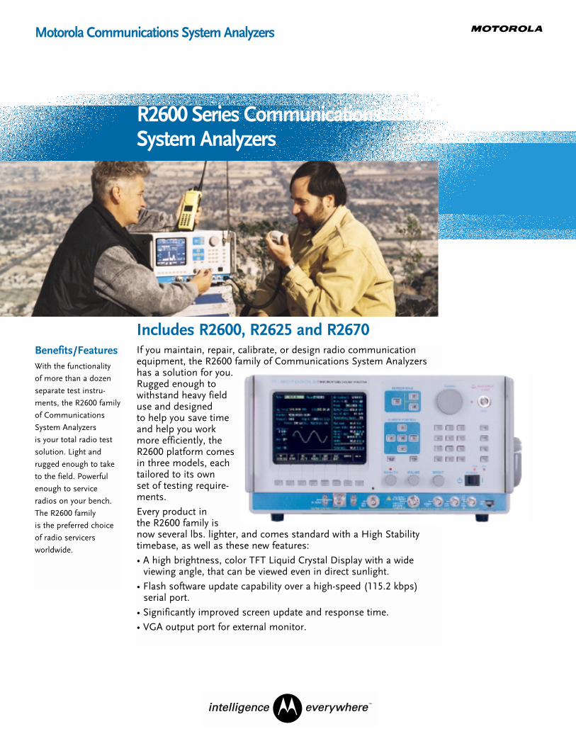
If you maintain, repair, calibrate, or design radio communicationequipment, the R2600 family of Communications System Analyzershas a solution for you.Rugged enough towithstand heavy fielduse and designed to help you save timeand help you workmore efficiently, theR2600 platform comesin three models, eachtailored to its own set of testing require-ments.
Every product in the R2600 family isnow several lbs. lighter, and comes standard with a High Stabilitytimebase, as well as these new features:
• A high brightness, color TFT Liquid Crystal Display with a wide viewing angle, that can be viewed even in direct sunlight.
• Flash software update capability over a high-speed (115.2 kbps) serial port.
• Significantly improved screen update and response time.
• VGA output port for external monitor.
R2600 Series Communications System Analyzers
Motorola Communications System Analyzers
Benefits/FeaturesWith the functionality
of more than a dozen
separate test instru-
ments, the R2600 family
of Communications
System Analyzers
is your total radio test
solution. Light and
rugged enough to take
to the field. Powerful
enough to service
radios on your bench.
The R2600 family
is the preferred choice
of radio servicers
worldwide.
Includes R2600, R2625 and R2670
TM

The Motorola R2600 Series.
The R2600 Series: The test solution for conventional two-way radios, ASTRO® 25 conventional and trunked radios, Motorola analog trunking, SECURENET, and more.
2
The R2600 family of Communications System Analyzers performs tests normally associated with these instruments:• RF Signal Generator• Sensitive Measurement Receiver• Spectrum Analyzer• Duplex Offset Generator• Frequency Counter• AC/DC Voltmeter• 50 kHz Oscilloscope• RF Wattmeter• Signal Strength Meter• Frequency Error Meter• SINAD Meter• Distortion Meter• Sweep Generator• Audio Generator• Modulation Analyzer• Signalling Simulator• RF Scan/Counter
Optional in R2600 & R2625; standard in R2670• Cable Fault Locator• Tracking Generator• Programmable Test Set Ups• High Performance Spectrum Analyzer with Markers
1) Display Zone for presentation of test data and waveforms
2) RF Control Zone for selecting RF test conditions
3) Cursor Zone keys provide simple, one-button access to any zone
4) Tuning Knob for easy change of any numeric entry: Digital precision with an analog feel
5) Off-the-air antenna port for sensitive receiver measurements
6) Color LCD
7) VGA output port
8) High speed serial port for remote control operation and flash softwareupdate capability
9) User-friendly, soft-touch keys for feature selection
10) Audio Control Zone for setting modulation conditions
11) Cursor Position keys allow instant cursor movement within a zone
12) Memory recall for up to 30 channelsincluding automatic scanning plus optional 15 user-programmable testsetups
13) Operator-selected, one-button access to special functions, printing and self-calibration
13
1 2
3 4 5
6
7
8
9
10
11
12
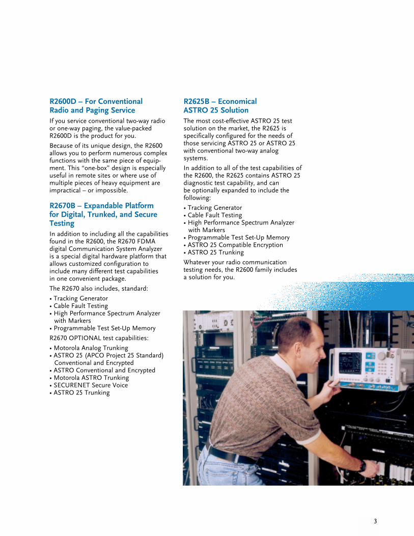
R2600D – For Conventional Radio and Paging ServiceIf you service conventional two-way radioor one-way paging, the value-packedR2600D is the product for you.
Because of its unique design, the R2600allows you to perform numerous complexfunctions with the same piece of equip-ment. This “one-box” design is especiallyuseful in remote sites or where use ofmultiple pieces of heavy equipment areimpractical – or impossible.
R2670B – Expandable Platform for Digital, Trunked, and SecureTestingIn addition to including all the capabilitiesfound in the R2600, the R2670 FDMA digital Communication System Analyzer is a special digital hardware platform thatallows customized configuration toinclude many different test capabilities in one convenient package.
The R2670 also includes, standard:
• Tracking Generator• Cable Fault Testing• High Performance Spectrum Analyzer
with Markers• Programmable Test Set-Up Memory
R2670 OPTIONAL test capabilities:
• Motorola Analog Trunking• ASTRO 25 (APCO Project 25 Standard)
Conventional and Encrypted• ASTRO Conventional and Encrypted• Motorola ASTRO Trunking• SECURENET Secure Voice• ASTRO 25 Trunking
3
R2625B – Economical ASTRO 25 SolutionThe most cost-effective ASTRO 25 testsolution on the market, the R2625 isspecifically configured for the needs ofthose servicing ASTRO 25 or ASTRO 25with conventional two-way analog systems.
In addition to all of the test capabilities ofthe R2600, the R2625 contains ASTRO 25diagnostic test capability, and can be optionally expanded to include the following:
• Tracking Generator• Cable Fault Testing• High Performance Spectrum Analyzer
with Markers• Programmable Test Set-Up Memory• ASTRO 25 Compatible Encryption• ASTRO 25 Trunking
Whatever your radio communication testing needs, the R2600 family includes a solution for you.
4
Feature Description Benefits
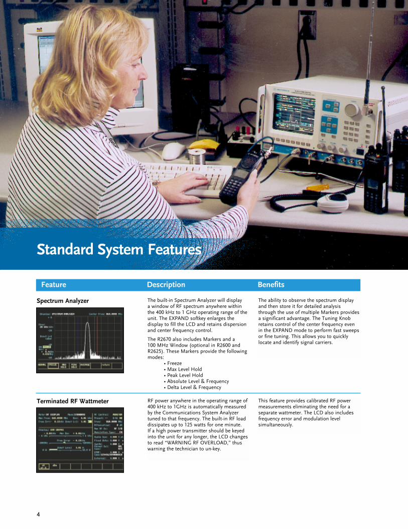
Spectrum Analyzer The built-in Spectrum Analyzer will display a window of RF spectrum anywhere withinthe 400 kHz to 1 GHz operating range of theunit. The EXPAND softkey enlarges the display to fill the LCD and retains dispersionand center frequency control.
The R2670 also includes Markers and a 100 MHz Window (optional in R2600 andR2625). These Markers provide the followingmodes:
• Freeze• Max Level Hold• Peak Level Hold• Absolute Level & Frequency• Delta Level & Frequency
The ability to observe the spectrum displayand then store it for detailed analysisthrough the use of multiple Markers providesa significant advantage. The Tuning Knobretains control of the center frequency evenin the EXPAND mode to perform fast sweepsor fine tuning. This allows you to quicklylocate and identify signal carriers.
Terminated RF Wattmeter RF power anywhere in the operating range of400 kHz to 1GHz is automatically measuredby the Communications System Analyzertuned to that frequency. The built-in RF loaddissipates up to 125 watts for one minute. If a high power transmitter should be keyedinto the unit for any longer, the LCD changesto read “WARNING RF OVERLOAD,” thuswarning the technician to un-key.
This feature provides calibrated RF powermeasurements eliminating the need for aseparate wattmeter. The LCD also includesfrequency error and modulation level simultaneously.
Standard System Features

Standard System Features – continued
Feature Description Benefits
Relative Signal Strength Meter In addition to reading frequency error andmodulation, a digital readout relative signalstrength meter has been included. Sensitivityis specified to -100 dBm at the antenna portfor FM signals and extends up to 125 watts at the RF I/O port. The LCD display will auto-matically convert to a terminating “watts”display as the level increases.
This feature, in conjunction with an externalantenna, allows remote monitoring of distanttransmitters to check for antenna, transmis-sion line or P.A. problems. Many techniciansalso find this feature convenient in perform-ing propagation studies to identify weak coverage areas.
5
Programmable Test Memory Channel Presets – The unit has 30 memorylocations which can be used to store presetchannel information. Channels can be easilyselected individually or automaticallyscanned over a user-defined range.
Channel Presets – This feature allows you toquickly access frequently used channel loca-tion information to speed testing. Scanningallows automatic monitoring and measure-ment of activity on channels of interest.
Programmable Test Setups (standard inR2670; optional in R2600 and R2625) – Youcan easily program and store up to 15 of themost commonly used test setups, includingall test conditions, measurement display for-mats, and levels. These memory positionsoperate fully independently from the channelpresets.
Programmable Test Setups (standard inR2670; optional in R2600 and R2625) – Youcan significantly reduce the number of keypresses required to set up the more com-monly used test setups, greatly increasingyour efficiency while promoting uniform test procedures. You can also assign a customname to the test for easy recall.
RF Scan/RF Counter Function RF Scan operates in the monitor mode and provides a function similar to a 1 GHzcounter. This feature automatically scans auser-defined frequency range to lock to thesignal applied. Any RF carrier above 20 MHzcan be located within 5 seconds or less andthe reception is displayed with digital readouts.
It is possible to locate and identify the operating frequencies of multi-channelradios. This feature allows the technician to conveniently and immediately verify theprogramming of a multi-channel radio. Byautomatically tuning the R2670 receiver tothe detected carrier, immediate measure-ment data can be taken without having toenter new frequency data via the keyboard.The 1 GHz counter on your bench is nowobsolete.
Duplex Full output level control from -130 dBm to 0 dBm over the entire range of the instru-ment is available from the RF I/O port (-130dBm up to -50 dBm) and the generation port(-80 dBm to 0 dBm). Variable offsets from 0 to ±55 MHz in 5 kHz steps are keypad-selectable.
The duplex generator provides enhancedcapability to service equipment such asrepeaters and full duplex radios, includingcellular telephones. Full RF level control aswell as full internal and external modulationcapability allows receiver desensitization andtransmitter tests to be performed simultane-ously through one port, if desired. Storage of test setups is available in memory forinstant recall.
Tracking Generator(standard in R2670; optional in R2600 and R2625)
The combining of the capabilities of thesweep generator and the spectrum analyzerinto a Tracking Generator function allows theuser to view the performance characteristicsof many RF filter devices. Display range isoperator selectable from a 200 kHz windowup to a 50 MHz window anywhere in the 400kHz to 1GHz spectrum.
Diagnosis and adjustment of critical receiverfront ends, IFs, helical filters, cavities, combiners and duplexers can be made in a few minutes, quickly and easily with theflexibility of a tracking generator at your fingertips.
Standard System Features – continued
Feature Description Benefits
Off-the-Air Sensitive Receiver The 2 microvolt sensitivity of the unit is available through the antenna port. Thisallows off-the-air monitoring of remote transmitters operating up to 1 GHz. Variablesquelch aids in picking up weak signals butcan be set tighter to ensure the proper S/Nratio for measurement accuracy.
This feature reduces service costs byenabling frequent preventive maintenanceparameter checks for system degradation orinterference identification without leaving the shop.
Electronic Software Updates Internal flash memory permits softwareupdates to be downloaded via the high speedserial interface port.
Quick and easy access to future softwareupdates.
6
RS-232/Serial Interface (standard)IEEE-488-2 Interface (optional)
A full bi-directional RS232 port is standardand includes the capability to respond to serial input command vocabulary and returnmeasurement results as a serial outputstream. Included are user-selectable baudrates (up to 115.2 Kbps) and start, stop andparity bit selection. In addition, this dualfunction port can drive a serial printer toprint out data and graphic displays. Theoptional IEEE remote interface option con-tains the necessary hardware and softwarefor IEEE-488-2.
Inconvenient trips to the service center are no longer necessary. If you have large volume repetitive testing requirements, this feature allows you to write your own programs to reduce test time costs. Printedresults can be used as part of the serviceshop’s internal quality control system andcan be used to demonstrate performance to the radio equipment user.
Cable Fault(standard in R2670; optional in R2600 and R2625)
Cable fault and length are RF measurementfeatures which help the technician isolatecable defects. Supported by on-screenprompts and user-selectable Help messages,you can quickly set up and accurately deter-mine the distance to a fault on a coaxialcable. The distance to fault (or cable length)is computed and displayed in feet or metricunits.
Cable fault locating techniques are mandato-ry for site servicing, where visual inspectionis not practical, safe, or effective in detectinghidden or cold-flow damage. The semi-auto-matic operation of the cable fault finder precludes the use of mathematical formulasand manual calculations, maximizing youron-site productivity.
General Purpose & Modulation Oscilloscope
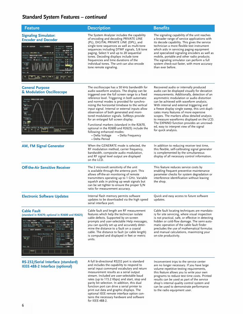
The oscilloscope has a 50 kHz bandwidth foraudio waveform analysis. The display can betriggered over the full screen range to a fixedreference level. Triggering in both automaticand normal modes is provided for synchro-nizing the horizontal timebase to the verticalinput signal. Internal or external inputs allowobservation of both generated and moni-tored modulation signals. Softkeys providefor an enlarged full screen display.
Functional markers (standard in the R2670,optional in the R2600 and R2625) include thefollowing enhanced modes:
• Delta Voltage • Delta Frequency• Delta Period
Recovered audio or internally produced audio can be displayed visually for deviationmeasurements. Additionally, detection of anasymmetric modulation or audio distortioncan be achieved with waveform analysis.With internal and external triggering and a freeze display single sweep, this unit dupli-cates many features of more expensivescopes. The markers allow detailed analysisto measure waveforms displayed on the LCD.The EXPAND function provides an uncrowd-ed, easy to interpret view of the signal for quick analysis.
AM, FM Signal Generator When the GENERATE mode is selected, theRF modulation method, carrier frequency,bandwidth, composite audio modulation,and RF signal level output are displayed on the LCD.
In addition to reducing receiver test time,this flexible, self-calibrating signal generatoris complemented by the simultaneous display of all necessary control information.
Signaling Simulator: Encoder and Decoder
The System Analyzer includes the capabilityof encoding and decoding PRIVATE LINE(PL), DIGITAL PRIVATE LINE (DPL), and single tone sequences as well as multi-tonesequences including DTMF signals, 5/6 tonepaging, Select V and up to 20 sequentialtones. Decoding displays include tone frequencies and time durations of the individual tones. The unit can also encodetone remote signaling.
The signaling capability of the unit reaches a broader range of service applications withits decode capability. This gives the servicetechnician a more flexible test instrumentwhich aids in servicing paging equipmentand specialized signaling encoders as well asmobile, portable and other radio products.The signaling simulator can perform a full system check-out faster, with more accuracythan ever before.
Motorola Trunking OptionFeature Description Benefits
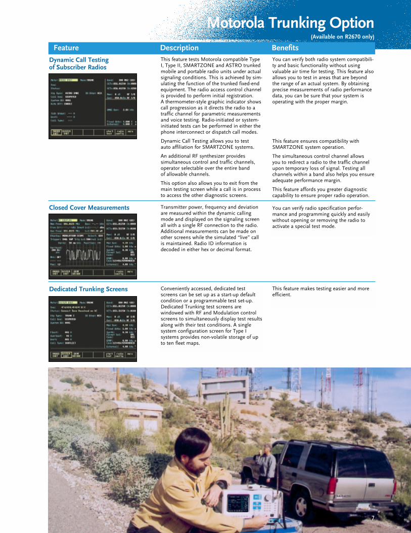
Dynamic Call Testing of Subscriber Radios
This feature tests Motorola compatible TypeI, Type II, SMARTZONE and ASTRO trunkedmobile and portable radio units under actualsignaling conditions. This is achieved by sim-ulating the function of the trunked fixed-endequipment. The radio access control channelis provided to perform initial registration. A thermometer-style graphic indicator showscall progression as it directs the radio to atraffic channel for parametric measurementsand voice testing. Radio-initiated or system-initiated tests can be performed in either thephone interconnect or dispatch call modes.
Dynamic Call Testing allows you to test auto affiliation for SMARTZONE systems.
An additional RF synthesizer provides simultaneous control and traffic channels,operator selectable over the entire band of allowable channels.
This option also allows you to exit from themain testing screen while a call is in processto access the other diagnostic screens.
You can verify both radio system compatibili-ty and basic functionality without using valuable air time for testing. This feature alsoallows you to test in areas that are beyondthe range of an actual system. By obtainingprecise measurements of radio performancedata, you can be sure that your system isoperating with the proper margin.
Closed Cover Measurements Transmitter power, frequency and deviationare measured within the dynamic callingmode and displayed on the signaling screenall with a single RF connection to the radio.Additional measurements can be made onother screens while the simulated “live” callis maintained. Radio ID information isdecoded in either hex or decimal format.
You can verify radio specification perfor-mance and programming quickly and easilywithout opening or removing the radio toactivate a special test mode.
Dedicated Trunking Screens Conveniently accessed, dedicated testscreens can be set up as a start-up defaultcondition or a programmable test set-up.Dedicated Trunking test screens are windowed with RF and Modulation controlscreens to simultaneously display test resultsalong with their test conditions. A single system configuration screen for Type I systems provides non-volatile storage of upto ten fleet maps.
This feature makes testing easier and moreefficient.
7
This feature ensures compatibility withSMARTZONE system operation.
The simultaneous control channel allows you to redirect a radio to the traffic channelupon temporary loss of signal. Testing allchannels within a band also helps you ensure adequate performance margin.
This feature affords you greater diagnosticcapability to ensure proper radio operation.
(Available on R2670 only)
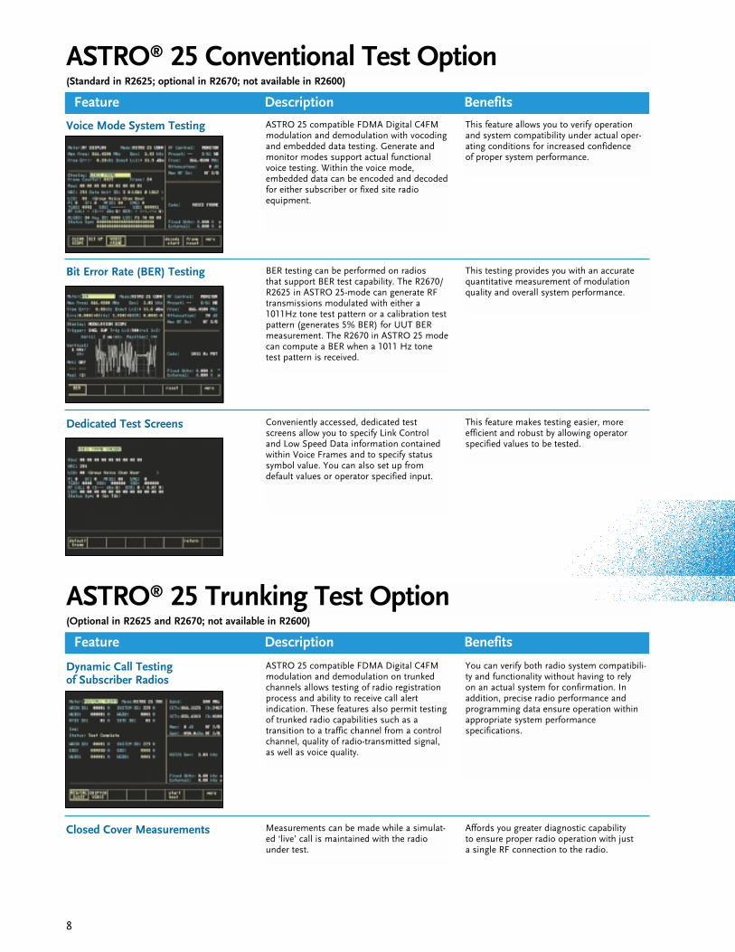
ASTRO® 25 Conventional Test Option
Feature Description Benefits
Voice Mode System Testing ASTRO 25 compatible FDMA Digital C4FMmodulation and demodulation with vocodingand embedded data testing. Generate andmonitor modes support actual functionalvoice testing. Within the voice mode, embedded data can be encoded and decodedfor either subscriber or fixed site radio equipment.
This feature allows you to verify operationand system compatibility under actual oper-ating conditions for increased confidence of proper system performance.
Bit Error Rate (BER) Testing BER testing can be performed on radios that support BER test capability. The R2670/R2625 in ASTRO 25-mode can generate RFtransmissions modulated with either a1011Hz tone test pattern or a calibration testpattern (generates 5% BER) for UUT BERmeasurement. The R2670 in ASTRO 25 modecan compute a BER when a 1011 Hz tonetest pattern is received.
This testing provides you with an accuratequantitative measurement of modulationquality and overall system performance.
Dedicated Test Screens Conveniently accessed, dedicated testscreens allow you to specify Link Control and Low Speed Data information containedwithin Voice Frames and to specify statussymbol value. You can also set up fromdefault values or operator specified input.
This feature makes testing easier, more efficient and robust by allowing operatorspecified values to be tested.
Dynamic Call Testing of Subscriber Radios
ASTRO 25 compatible FDMA Digital C4FMmodulation and demodulation on trunkedchannels allows testing of radio registrationprocess and ability to receive call alert indication. These features also permit testingof trunked radio capabilities such as a transition to a traffic channel from a controlchannel, quality of radio-transmitted signal,as well as voice quality.
You can verify both radio system compatibili-ty and functionality without having to rely on an actual system for confirmation. Inaddition, precise radio performance and programming data ensure operation withinappropriate system performance specifications.
Closed Cover Measurements Measurements can be made while a simulat-ed ‘live’ call is maintained with the radiounder test.
8
(Standard in R2625; optional in R2670; not available in R2600)
ASTRO® 25 Trunking Test Option
Feature Description Benefits
(Optional in R2625 and R2670; not available in R2600)
Affords you greater diagnostic capability to ensure proper radio operation with just a single RF connection to the radio.
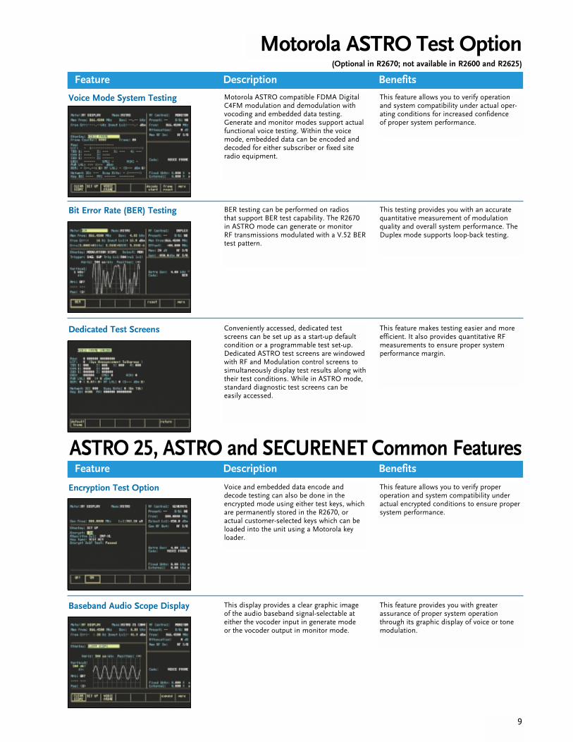
Motorola ASTRO Test Option
Feature Description Benefits
Feature Description Benefits
9
Dedicated Test Screens Conveniently accessed, dedicated testscreens can be set up as a start-up defaultcondition or a programmable test set-up.Dedicated ASTRO test screens are windowedwith RF and Modulation control screens tosimultaneously display test results along withtheir test conditions. While in ASTRO mode, standard diagnostic test screens can be easily accessed.
This feature makes testing easier and moreefficient. It also provides quantitative RFmeasurements to ensure proper system performance margin.
Voice Mode System Testing Motorola ASTRO compatible FDMA DigitalC4FM modulation and demodulation withvocoding and embedded data testing.Generate and monitor modes support actualfunctional voice testing. Within the voicemode, embedded data can be encoded anddecoded for either subscriber or fixed siteradio equipment.
This feature allows you to verify operationand system compatibility under actual oper-ating conditions for increased confidence of proper system performance.
Bit Error Rate (BER) Testing BER testing can be performed on radios that support BER test capability. The R2670in ASTRO mode can generate or monitor RF transmissions modulated with a V.52 BERtest pattern.
This testing provides you with an accuratequantitative measurement of modulationquality and overall system performance. TheDuplex mode supports loop-back testing.
ASTRO 25, ASTRO and SECURENET Common Features
Encryption Test Option Voice and embedded data encode anddecode testing can also be done in theencrypted mode using either test keys, whichare permanently stored in the R2670, or actual customer-selected keys which can beloaded into the unit using a Motorola keyloader.
This feature allows you to verify proper operation and system compatibility underactual encrypted conditions to ensure propersystem performance.
Baseband Audio Scope Display This display provides a clear graphic imageof the audio baseband signal-selectable ateither the vocoder input in generate mode or the vocoder output in monitor mode.
This feature provides you with greater assurance of proper system operationthrough its graphic display of voice or tonemodulation.
(Optional in R2670; not available in R2600 and R2625)

Motorola SECURENET Test Option
Voice Mode System Testing Voice mode system testing providesMotorola SECURENET-compatible modulation and demodulation with vocod-ing. Generate and monitor modes supportactual functional voice testing in the encrypt-ed mode using either test keys, which arepermanently stored in the R2670, or actualcustomer-selected keys from a separate DXkey loader. The R2670 also emulates an AX,BX, or CX key loader which can be used todownload test keys to a compatible radio.
This feature allows you to verify operationand system compatibility under actualencrypted voice conditions to ensure propersystem performance.
Bit Error Rate (BER) Testing
Dedicated Test Screens
BER can be measured using the built-in V.52test pattern generator. This standard, non-encrypted pattern can be used to either modulate the Generator or inject into a radioor system under test via the baseband out-put. This BER pattern can then be recoveredfrom the radio system either through theR2670’s Monitor receiver or its basebandinput to perform a closed loop BER test. TheBER test is also available within the unit’sDuplex mode.
Conveniently accessed, dedicated testscreens can be set up as a start-up defaultcondition or a programmable test set-up.Dedicated SECURENET test screens are windowed with RF and Modulation controlscreens to simultaneously display test resultsalong with their test conditions. While inSECURENET mode, standard diagnostic testscreens can be easily accessed.
This testing provides you with an accuratequantitative measurement of modulationquality and overall system performance. TheDuplex mode supports loop-back testing.
This feature makes testing easier and moreefficient. It also provides quantitative RFmeasurements to ensure proper system performance margin.
Feature Description Benefits
10
Available only in R2670
11
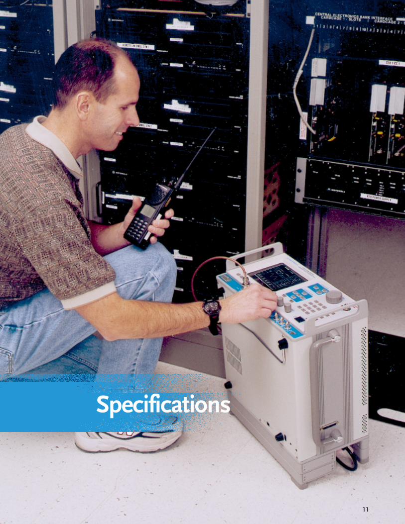
Specifications
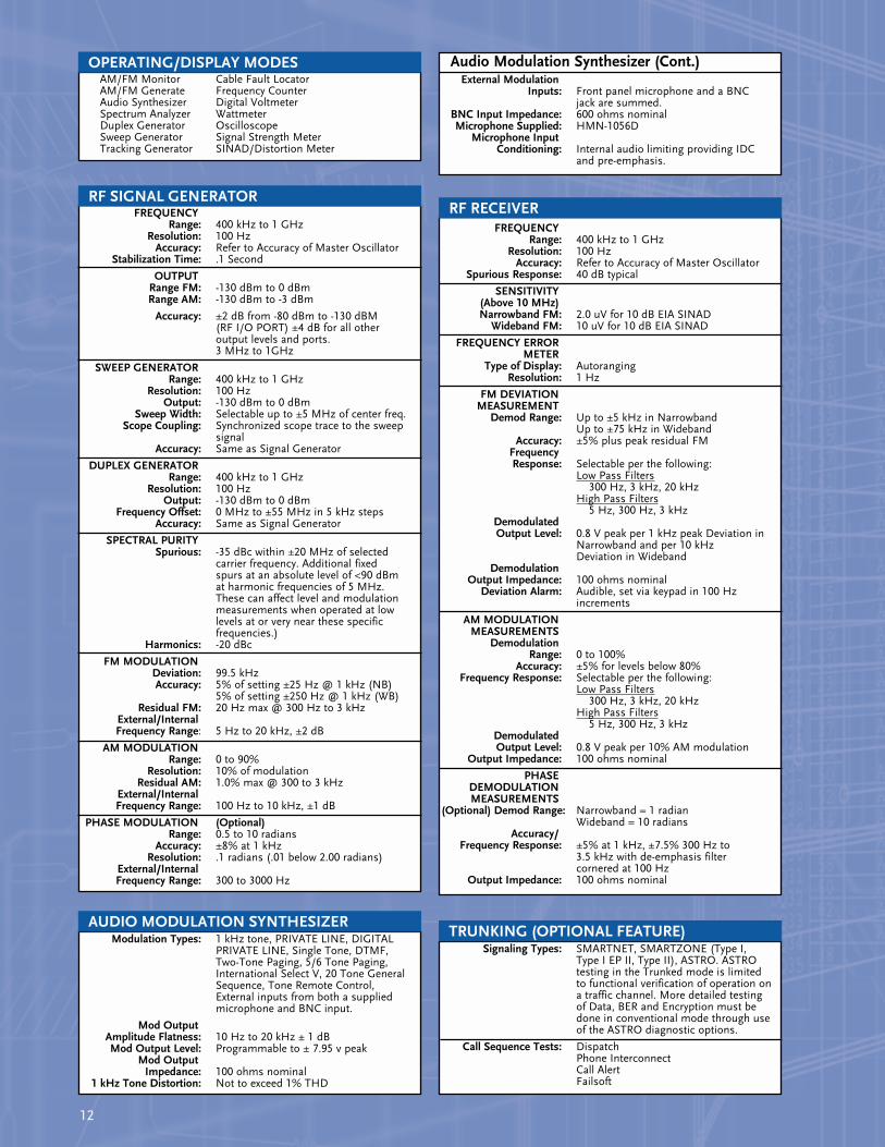
AM/FM Monitor Cable Fault LocatorAM/FM Generate Frequency CounterAudio Synthesizer Digital VoltmeterSpectrum Analyzer WattmeterDuplex Generator OscilloscopeSweep Generator Signal Strength MeterTracking Generator SINAD/Distortion Meter
FREQUENCYRange: 400 kHz to 1 GHz
Resolution: 100 HzAccuracy: Refer to Accuracy of Master Oscillator
Stabilization Time: .1 Second
OUTPUTRange FM: -130 dBm to 0 dBmRange AM: -130 dBm to -3 dBm
Accuracy: ±2 dB from -80 dBm to -130 dBM (RF I/O PORT) ±4 dB for all other output levels and ports. 3 MHz to 1GHz
SWEEP GENERATORRange: 400 kHz to 1 GHz
Resolution: 100 HzOutput: -130 dBm to 0 dBm
Sweep Width: Selectable up to ±5 MHz of center freq.Scope Coupling: Synchronized scope trace to the sweep
signalAccuracy: Same as Signal Generator
DUPLEX GENERATORRange: 400 kHz to 1 GHz
Resolution: 100 HzOutput: -130 dBm to 0 dBm
Frequency Offset: 0 MHz to ±55 MHz in 5 kHz stepsAccuracy: Same as Signal Generator
SPECTRAL PURITYSpurious: -35 dBc within ±20 MHz of selected
carrier frequency. Additional fixed spurs at an absolute level of <90 dBm at harmonic frequencies of 5 MHz. These can affect level and modulation measurements when operated at low levels at or very near these specific frequencies.)
Harmonics: -20 dBc
FM MODULATIONDeviation: 99.5 kHzAccuracy: 5% of setting ±25 Hz @ 1 kHz (NB)
5% of setting ±250 Hz @ 1 kHz (WB)Residual FM: 20 Hz max @ 300 Hz to 3 kHz
External/Internal Frequency Range: 5 Hz to 20 kHz, ±2 dB
AM MODULATIONRange: 0 to 90%
Resolution: 10% of modulationResidual AM: 1.0% max @ 300 to 3 kHz
External/InternalFrequency Range: 100 Hz to 10 kHz, ±1 dB
PHASE MODULATION (Optional)Range: 0.5 to 10 radians
Accuracy: ±8% at 1 kHzResolution: .1 radians (.01 below 2.00 radians)
External/InternalFrequency Range: 300 to 3000 Hz
Audio Modulation Synthesizer (Cont.)External Modulation
Inputs: Front panel microphone and a BNC jack are summed.
BNC Input Impedance: 600 ohms nominalMicrophone Supplied: HMN-1056D
Microphone InputConditioning: Internal audio limiting providing IDC
and pre-emphasis.
FREQUENCYRange: 400 kHz to 1 GHz
Resolution: 100 HzAccuracy: Refer to Accuracy of Master Oscillator
Spurious Response: 40 dB typical
SENSITIVITY(Above 10 MHz)Narrowband FM: 2.0 uV for 10 dB EIA SINAD
Wideband FM: 10 uV for 10 dB EIA SINAD
FREQUENCY ERRORMETER
Type of Display: AutorangingResolution: 1 Hz
FM DEVIATIONMEASUREMENT
Demod Range: Up to ±5 kHz in NarrowbandUp to ±75 kHz in Wideband
Accuracy: ±5% plus peak residual FMFrequencyResponse: Selectable per the following:
Low Pass Filters300 Hz, 3 kHz, 20 kHz
High Pass Filters5 Hz, 300 Hz, 3 kHz
DemodulatedOutput Level: 0.8 V peak per 1 kHz peak Deviation in
Narrowband and per 10 kHz Deviation in Wideband
DemodulationOutput Impedance: 100 ohms nominal
Deviation Alarm: Audible, set via keypad in 100 Hz increments
AM MODULATIONMEASUREMENTS
DemodulationRange: 0 to 100%
Accuracy: ±5% for levels below 80%Frequency Response: Selectable per the following:
Low Pass Filters300 Hz, 3 kHz, 20 kHz
High Pass Filters5 Hz, 300 Hz, 3 kHz
DemodulatedOutput Level: 0.8 V peak per 10% AM modulation
Output Impedance: 100 ohms nominal
PHASEDEMODULATIONMEASUREMENTS
(Optional) Demod Range: Narrowband = 1 radianWideband = 10 radians
Accuracy/Frequency Response: ±5% at 1 kHz, ±7.5% 300 Hz to
3.5 kHz with de-emphasis filter cornered at 100 Hz
Output Impedance: 100 ohms nominal
Modulation Types: 1 kHz tone, PRIVATE LINE, DIGITAL PRIVATE LINE, Single Tone, DTMF, Two-Tone Paging, 5/6 Tone Paging, International Select V, 20 Tone General Sequence, Tone Remote Control, External inputs from both a supplied microphone and BNC input.
Mod OutputAmplitude Flatness: 10 Hz to 20 kHz ± 1 dBMod Output Level: Programmable to ± 7.95 v peak
Mod OutputImpedance: 100 ohms nominal
1 kHz Tone Distortion: Not to exceed 1% THD
12
Signaling Types: SMARTNET, SMARTZONE (Type I, Type I EP II, Type II), ASTRO. ASTROtesting in the Trunked mode is limited to functional verification of operation on a traffic channel. More detailed testing of Data, BER and Encryption must be done in conventional mode through use of the ASTRO diagnostic options.
Call Sequence Tests: DispatchPhone InterconnectCall AlertFailsoft
TRUNKING (OPTIONAL FEATURE)
OPERATING/DISPLAY MODES
RF SIGNAL GENERATOR
AUDIO MODULATION SYNTHESIZER
RF RECEIVER
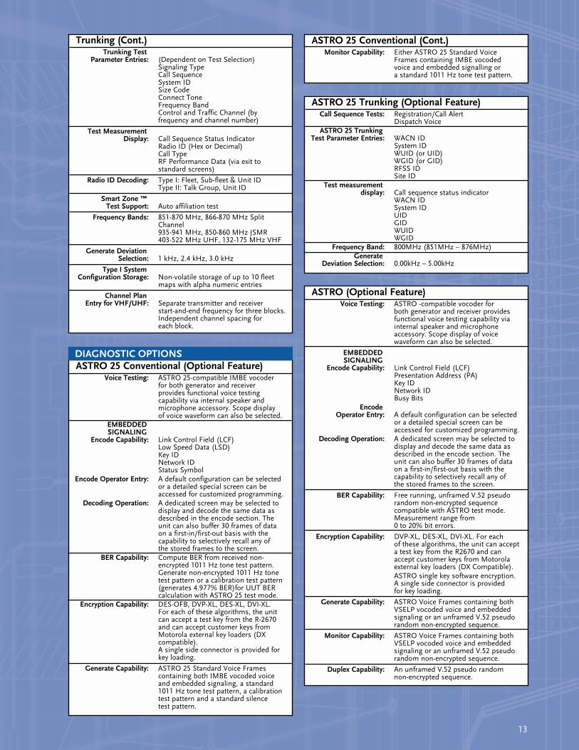
ASTRO (Optional Feature)Voice Testing: ASTRO -compatible vocoder for
both generator and receiver provides functional voice testing capability via internal speaker and microphone accessory. Scope display of voice waveform can also be selected.
EMBEDDEDSIGNALING
Encode Capability: Link Control Field (LCF)Presentation Address (PA)Key IDNetwork IDBusy Bits
EncodeOperator Entry: A default configuration can be selected
or a detailed special screen can be accessed for customized programming.
Decoding Operation: A dedicated screen may be selected to display and decode the same data as described in the encode section. The unit can also buffer 30 frames of data on a first-in/first-out basis with the capability to selectively recall any of the stored frames to the screen.
BER Capability: Free running, unframed V.52 pseudo random non-encrypted sequence compatible with ASTRO test mode. Measurement range from 0 to 20% bit errors.
Encryption Capability: DVP-XL, DES-XL, DVI-XL. For each of these algorithms, the unit can accept a test key from the R2670 and can accept customer keys from Motorola external key loaders (DX Compatible).ASTRO single key software encryption.A single side connector is provided for key loading.
Generate Capability: ASTRO Voice Frames containing both VSELP vocoded voice and embedded signaling or an unframed V.52 pseudo random non-encrypted sequence.
Monitor Capability: ASTRO Voice Frames containing both VSELP vocoded voice and embedded signaling or an unframed V.52 pseudo random non-encrypted sequence.
Duplex Capability: An unframed V.52 pseudo random non-encrypted sequence.
ASTRO 25 Conventional (Cont.)Monitor Capability: Either ASTRO 25 Standard Voice
Frames containing IMBE vocoded voice and embedded signalling or a standard 1011 Hz tone test pattern.
ASTRO 25 Conventional (Optional Feature)Voice Testing: ASTRO 25-compatible IMBE vocoder
for both generator and receiver provides functional voice testing capability via internal speaker and microphone accessory. Scope display of voice waveform can also be selected.
EMBEDDEDSIGNALING
Encode Capability: Link Control Field (LCF)Low Speed Data (LSD)Key IDNetwork IDStatus Symbol
Encode Operator Entry: A default configuration can be selected or a detailed special screen can be accessed for customized programming.
Decoding Operation: A dedicated screen may be selected to display and decode the same data as described in the encode section. The unit can also buffer 30 frames of data on a first-in/first-out basis with the capability to selectively recall any of the stored frames to the screen.
BER Capability: Compute BER from received non-encrypted 1011 Hz tone test pattern. Generate non-encrypted 1011 Hz tone test pattern or a calibration test pattern (generates 4.977% BER)for UUT BER calculation with ASTRO 25 test mode.
Encryption Capability: DES-OFB, DVP-XL, DES-XL, DVI-XL.For each of these algorithms, the unit can accept a test key from the R-2670 and can accept customer keys from Motorola external key loaders (DX compatible).A single side connector is provided for key loading.
Generate Capability: ASTRO 25 Standard Voice Frames containing both IMBE vocoded voice and embedded signaling, a standard 1011 Hz tone test pattern, a calibration test pattern and a standard silence test pattern.
ASTRO 25 Trunking (Optional Feature)Call Sequence Tests: Registration/Call Alert
Dispatch VoiceASTRO 25 Trunking
Test Parameter Entries: WACN IDSystem IDWUID (or UID)WGID (or GID)RFSS IDSite ID
Test measurementdisplay: Call sequence status indicator
WACN IDSystem IDUIDGIDWUIDWGID
Frequency Band: 800MHz (851MHz – 876MHz)Generate
Deviation Selection: 0.00kHz – 5.00kHz
Trunking (Cont.)Trunking Test
Parameter Entries: (Dependent on Test Selection)Signaling TypeCall SequenceSystem IDSize CodeConnect ToneFrequency BandControl and Traffic Channel (by frequency and channel number)
Test MeasurementDisplay: Call Sequence Status Indicator
Radio ID (Hex or Decimal)Call TypeRF Performance Data (via exit to standard screens)
Radio ID Decoding: Type I: Fleet, Sub-fleet & Unit ID Type II: Talk Group, Unit ID
Smart Zone ™Test Support: Auto affiliation test
Frequency Bands: 851-870 MHz, 866-870 MHz Split Channel935-941 MHz, 850-860 MHz JSMR403-522 MHz UHF, 132-175 MHz VHF
Generate DeviationSelection: 1 kHz, 2.4 kHz, 3.0 kHz
Type I SystemConfiguration Storage: Non-volatile storage of up to 10 fleet
maps with alpha numeric entries
Channel PlanEntry for VHF/UHF: Separate transmitter and receiver
start-and-end frequency for three blocks. Independent channel spacing for each block.
DIAGNOSTIC OPTIONS
13
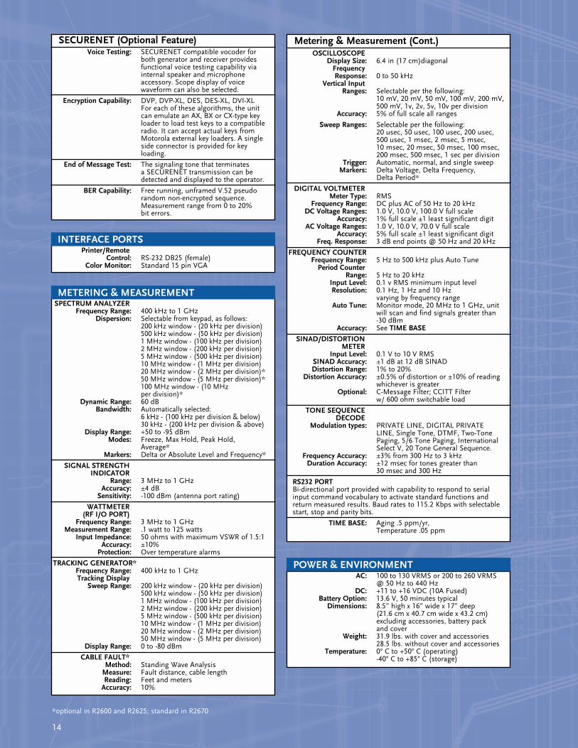
SPECTRUM ANALYZERFrequency Range: 400 kHz to 1 GHz
Dispersion: Selectable from keypad, as follows:200 kHz window - (20 kHz per division)500 kHz window - (50 kHz per division)1 MHz window - (100 kHz per division)2 MHz window - (200 kHz per division)5 MHz window - (500 kHz per division)10 MHz window - (1 MHz per division)20 MHz window - (2 MHz per division)*50 MHz window - (5 MHz per division)*100 MHz window - (10 MHz per division)*
Dynamic Range: 60 dBBandwidth: Automatically selected:
6 kHz - (100 kHz per division & below) 30 kHz - (200 kHz per division & above)
Display Range: +50 to -95 dBmModes: Freeze, Max Hold, Peak Hold,
Average*Markers: Delta or Absolute Level and Frequency*
SIGNAL STRENGTHINDICATOR
Range: 3 MHz to 1 GHzAccuracy: ±4 dB
Sensitivity: -100 dBm (antenna port rating)
WATTMETER(RF I/O PORT)
Frequency Range: 3 MHz to 1 GHzMeasurement Range: .1 watt to 125 watts
Input Impedance: 50 ohms with maximum VSWR of 1.5:1Accuracy: ±10%
Protection: Over temperature alarms
TRACKING GENERATOR*Frequency Range: 400 kHz to 1 GHzTracking Display
Sweep Range: 200 kHz window - (20 kHz per division)500 kHz window - (50 kHz per division)1 MHz window - (100 kHz per division)2 MHz window - (200 kHz per division)5 MHz window - (500 kHz per division)10 MHz window - (1 MHz per division)20 MHz window - (2 MHz per division)50 MHz window - (5 MHz per division)
Display Range: 0 to -80 dBm
CABLE FAULT*Method: Standing Wave Analysis
Measure: Fault distance, cable lengthReading: Feet and meters
Accuracy: 10%
Metering & Measurement (Cont.)OSCILLOSCOPE
Display Size: 6.4 in (17 cm)diagonalFrequencyResponse: 0 to 50 kHz
Vertical InputRanges: Selectable per the following:
10 mV, 20 mV, 50 mV, 100 mV, 200 mV, 500 mV, 1v, 2v, 5v, 10v per division
Accuracy: 5% of full scale all ranges
Sweep Ranges: Selectable per the following:20 usec, 50 usec, 100 usec, 200 usec, 500 usec, 1 msec, 2 msec, 5 msec, 10 msec, 20 msec, 50 msec, 100 msec, 200 msec, 500 msec, 1 sec per division
Trigger: Automatic, normal, and single sweepMarkers: Delta Voltage, Delta Frequency,
Delta Period*
DIGITAL VOLTMETERMeter Type: RMS
Frequency Range: DC plus AC of 50 Hz to 20 kHzDC Voltage Ranges: 1.0 V, 10.0 V, 100.0 V full scale
Accuracy: 1% full scale ±1 least significant digitAC Voltage Ranges: 1.0 V, 10.0 V, 70.0 V full scale
Accuracy: 5% full scale ±1 least significant digitFreq. Response: 3 dB end points @ 50 Hz and 20 kHz
FREQUENCY COUNTERFrequency Range: 5 Hz to 500 kHz plus Auto Tune
Period CounterRange: 5 Hz to 20 kHz
Input Level: 0.1 v RMS minimum input levelResolution: 0.1 Hz, 1 Hz and 10 Hz
varying by frequency rangeAuto Tune: Monitor mode, 20 MHz to 1 GHz, unit
will scan and find signals greater than -30 dBm
Accuracy: See TIME BASE
SINAD/DISTORTIONMETER
Input Level: 0.1 V to 10 V RMSSINAD Accuracy: ±1 dB at 12 dB SINADDistortion Range: 1% to 20%
Distortion Accuracy: ±0.5% of distortion or ±10% of reading whichever is greater
Optional: C-Message Filter; CCITT Filter w/ 600 ohm switchable load
TONE SEQUENCEDECODE
Modulation types: PRIVATE LINE, DIGITAL PRIVATE LINE, Single Tone, DTMF, Two-Tone Paging, 5/6 Tone Paging, International Select V, 20 Tone General Sequence.
Frequency Accuracy: ±3% from 300 Hz to 3 kHzDuration Accuracy: ±12 msec for tones greater than
30 msec and 300 Hz
RS232 PORTBi-directional port provided with capability to respond to serial input command vocabulary to activate standard functions and return measured results. Baud rates to 115.2 Kbps with selectable start, stop and parity bits.
TIME BASE: Aging .5 ppm/yr, Temperature .05 ppm
14
SECURENET (Optional Feature)Voice Testing: SECURENET compatible vocoder for
both generator and receiver provides functional voice testing capability via internal speaker and microphone accessory. Scope display of voice waveform can also be selected.
Encryption Capability: DVP, DVP-XL, DES, DES-XL, DVI-XLFor each of these algorithms, the unit can emulate an AX, BX or CX-type key loader to load test keys to a compatibleradio. It can accept actual keys from Motorola external key loaders. A single side connector is provided for key loading.
End of Message Test: The signaling tone that terminates a SECURENET transmission can be detected and displayed to the operator.
BER Capability: Free running, unframed V.52 pseudo random non-encrypted sequence.Measurement range from 0 to 20% bit errors.
Printer/RemoteControl: RS-232 DB25 (female)
Color Monitor: Standard 15 pin VGA
AC: 100 to 130 VRMS or 200 to 260 VRMS @ 50 Hz to 440 Hz
DC: +11 to +16 VDC (10A Fused)Battery Option: 13.6 V, 50 minutes typical
Dimensions: 8.5” high x 16” wide x 17” deep(21.6 cm x 40.7 cm wide x 43.2 cm) excluding accessories, battery pack and cover
Weight: 31.9 lbs. with cover and accessories28.5 lbs. without cover and accessories
Temperature: 0° C to +50° C (operating)-40° C to +85° C (storage)
INTERFACE PORTS
POWER & ENVIRONMENT
METERING & MEASUREMENT
*optional in R2600 and R2625; standard in R2670
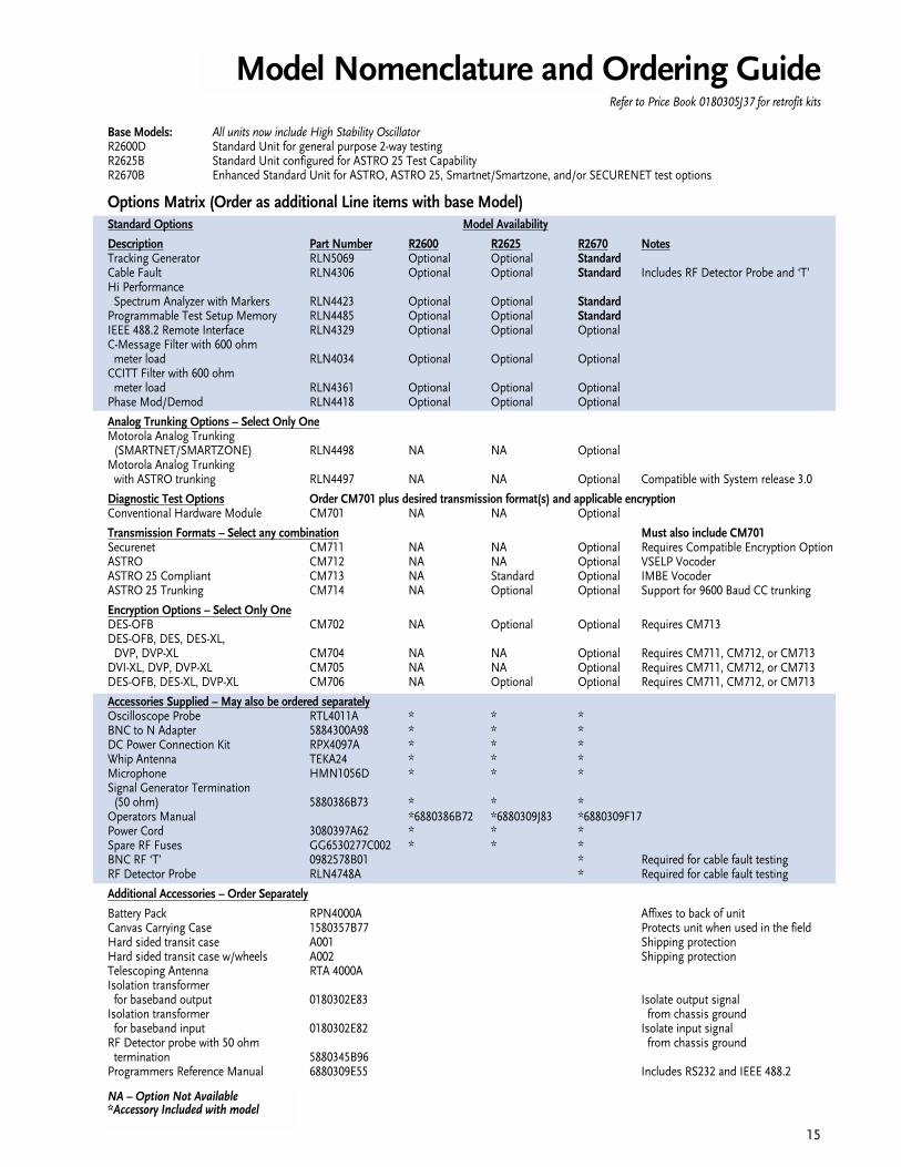
Base Models: All units now include High Stability OscillatorR2600D Standard Unit for general purpose 2-way testingR2625B Standard Unit configured for ASTRO 25 Test CapabilityR2670B Enhanced Standard Unit for ASTRO, ASTRO 25, Smartnet/Smartzone, and/or SECURENET test options
Options Matrix (Order as additional Line items with base Model)Standard Options Model Availability
Description Part Number R2600 R2625 R2670 NotesTracking Generator RLN5069 Optional Optional StandardCable Fault RLN4306 Optional Optional Standard Includes RF Detector Probe and ‘T’ Hi Performance
Spectrum Analyzer with Markers RLN4423 Optional Optional StandardProgrammable Test Setup Memory RLN4485 Optional Optional StandardIEEE 488.2 Remote Interface RLN4329 Optional Optional OptionalC-Message Filter with 600 ohm
meter load RLN4034 Optional Optional OptionalCCITT Filter with 600 ohm
meter load RLN4361 Optional Optional OptionalPhase Mod/Demod RLN4418 Optional Optional Optional
Analog Trunking Options – Select Only OneMotorola Analog Trunking
(SMARTNET/SMARTZONE) RLN4498 NA NA OptionalMotorola Analog Trunking
with ASTRO trunking RLN4497 NA NA Optional Compatible with System release 3.0
Diagnostic Test Options Order CM701 plus desired transmission format(s) and applicable encryptionConventional Hardware Module CM701 NA NA Optional
Transmission Formats – Select any combination Must also include CM701Securenet CM711 NA NA Optional Requires Compatible Encryption OptionASTRO CM712 NA NA Optional VSELP VocoderASTRO 25 Compliant CM713 NA Standard Optional IMBE VocoderASTRO 25 Trunking CM714 NA Optional Optional Support for 9600 Baud CC trunking
Encryption Options – Select Only OneDES-OFB CM702 NA Optional Optional Requires CM713DES-OFB, DES, DES-XL,
DVP, DVP-XL CM704 NA NA Optional Requires CM711, CM712, or CM713DVI-XL, DVP, DVP-XL CM705 NA NA Optional Requires CM711, CM712, or CM713DES-OFB, DES-XL, DVP-XL CM706 NA Optional Optional Requires CM711, CM712, or CM713
Accessories Supplied – May also be ordered separatelyOscilloscope Probe RTL4011A * * *BNC to N Adapter 5884300A98 * * *DC Power Connection Kit RPX4097A * * *Whip Antenna TEKA24 * * *Microphone HMN1056D * * *Signal Generator Termination
(50 ohm) 5880386B73 * * *Operators Manual *6880386B72 *6880309J83 *6880309F17Power Cord 3080397A62 * * *Spare RF Fuses GG6530277C002 * * *BNC RF ‘T’ 0982578B01 * Required for cable fault testingRF Detector Probe RLN4748A * Required for cable fault testing
Additional Accessories – Order Separately
Battery Pack RPN4000A Affixes to back of unitCanvas Carrying Case 1580357B77 Protects unit when used in the fieldHard sided transit case A001 Shipping protectionHard sided transit case w/wheels A002 Shipping protectionTelescoping Antenna RTA 4000AIsolation transformer
for baseband output 0180302E83 Isolate output signalIsolation transformer from chassis ground
for baseband input 0180302E82 Isolate input signalRF Detector probe with 50 ohm from chassis ground
termination 5880345B96Programmers Reference Manual 6880309E55 Includes RS232 and IEEE 488.2
15
Model Nomenclature and Ordering GuideRefer to Price Book 0180305J37 for retrofit kits
NA – Option Not Available*Accessory Included with model

SERVICE, MAINTENANCE AND TECHNICAL SUPPORT
For service on your Motorola test equipment in the U.S. contact: Motorola Test Equipment Service Depot,
1313 E. Algonquin Road, Dock 4, Schaumburg, IL 60196. 1-800-323-6967.
Service is also available in many areas other than the U.S.Please contact your local Motorola sales or service
representative for the facility nearest you.
MOTOROLA, the Motorola logo, ASTRO and ASTRO 25are registered trademarks of Motorola Inc.
ASTRO, SABER, SMARTNET, SMARTZONE and SECURENETare trademarks of Motorola Inc.
© COPYRIGHT 2001 MOTOROLA, INC. SCHAUMBURG, ILPRINTED IN THE U.S.A. 3/01
Pricing and specifications subject to change without notice.
0180305J36
Motorola 1313 E. Algonquin RoadSchaumburg, IL 60196
Please call the Motorola representative in your area for assistance with product information, pricing and orders.
In the United States call or FAX:
Telephone: 1-800-422-4210FAX: 1-800-622-6210
Federal Government CustomersTelephone: 1-800-826-1913
FAX: 1-800-526-8641
http://AccessSecure.mot.com/Accesspoint
®
TM