search.jsp?R=19770020241 2018-07 … · 3 Recipient's Catalog No. 4 Title and Subtitle 5 Report ......
27
https://ntrs.nasa.gov/search.jsp?R=19770020241 2018-07-30T09:42:33+00:00Z
Transcript of search.jsp?R=19770020241 2018-07 … · 3 Recipient's Catalog No. 4 Title and Subtitle 5 Report ......

https://ntrs.nasa.gov/search.jsp?R=19770020241 2018-07-30T09:42:33+00:00Z

3 Recipient's Catalog No.
4 Title and Subtitle 5 Report [>at?
SOURCE
7 Author(s) 8 Performing Organization Report No
Lewis Research Center National Aeronautics and Space Administration
National Aeronautics and Space Administration
15 Supplementary Notes
I 16. Abstract
System tes t s were performed in which integrally regulated so la r a r r a y s (IRSA's) were used to directly power the beam and accelerator loads of a 30-cm-diameter, electron bombardment, mercury ion thruster . The remaining thruster loads were supplied from conventional power- processing circuits. This combination of IRSA's and conventional c i rcui ts formed a "hybrid" power processor . Thruster performance was evaluated at 3/4- and 1-A beam currents with both the IRSA-hybrid and conventional power processors and was found to be identical for both systems. Power processing is significantly more efficient with the hybrid system. System dynamics and IRSA response to thruster a r c s were also examined.
17. Key Words (Suggested by Author(s) ) 18. Distribution Statement
Ion propulsion Unclassified - unlimited Power conditioning STAR category 20 Solar electric propulsion
19. Security Classif. (of this report) 20. Security Classif. (of this page)
U ~ c l a ~ ~ ~ ~ i e ~
' For sale by the National lechmcal I i i fori i iation Serv ice, Spr i i igf ie id Siirgiiiia 22161

M F
THRUSTER WITH INTEGRALLY REGU
ARRAY POWER SOURCE
by S u z a n n e T. Gooder
Lewis Research Cen te r
SUMMARY
System tests were performed in which integrally regulated solar a r r ays (IRSA's) w e r e used to directly power the beam and accelerator loads of a 30-centimeter-diameter, electron bombardment, mercury ion thruster. The remaining thruster loads were sup- plied from conventional power -processing circuits. The experiment was performed to demonstrate the feasibility of powering major ion thruster loads directly from regulated solar a r r ays and to evaluate the effects of such operation on thruster steady-state and dynamic performance.
beam current with conventional and IRSA power systems, and steady-state electrical waveforms were recorded, Performance was also measured at 3/4 -ampere beam cur - rent. Thruster performance was independent of the power -processing system used. Steady -state waveforms were also essentially the same. Perveance of the thruster grids was measured with the conventional and the IRSA systems. Again, no significant differ- ences were found between the two.
power-processing system and a n IRSA system l ies in the electrical efficiency of the power system. The conventional power circuits for the beam supply are very efficient - approximately 95 percent. However, IRSA efficiency is about 99.9 percent. This loss reduction yields a direct reduction in thermal control system mass, and the reduced power loss also implies a reduction in needed solar a r r ay area.
Thruster performance was measured under several operating conditions at 1 -ampere
The single difference observed between thruster operation with a conventional

frequency amplifiers, the necessary power processors a r e heavy, complex, and expen- sive to design and build and a r e a substantial burden on the spacecraft thermal control system. Considerable work is being done on alternate power-processing concepts to reduce these spacecraft penalties.
an implementation of which is the high-voltage solar a r r ay (HVSA). The I provides regulated direct- current power from a controlled solar a r r ay d i r using load without an intervening power processor. References 1 and 2 descr ibe some results obtained with prototype IRSA systems operating lower power active loads. Typ- ically, the solar a r r ay is subdivided into a number of s e r i e s and/or parallel blocks, some of which a r e paralleled by shorting switches, The a r r ay output is regulated by closed-loop, digital control logic that selectively actuates the shorting switches. The switchable blocks a r e usually binary weighted in voltage to minimize the number of switches, but this is not a concept requirement. Figure 1 is a block diagram of a typ- ical IRSA system consisting of the solar a r r ay , regulation switches, control logic, a sensor, and a direct-current load. A s can be seen from the diagram, the IRSA system offers a number of advantages over a conventional power processor. Heavy power switches, t ransformers , rectifiers, and filters a r e replaced by digital logic and solid- state shorting switches. Instead of the 5- to 15-percent power dissipation of conventional power processors, the IRSA system approaches zero dissipation at maximum loading when all the shorting switches a r e off. Overall system reliability improves from two factors: the reduced number of parts and the absence of s e r i e s elements between the power source and the load, IRSA has one further advantage - adaptability, A single regulator design can be employed to regulate any solar array; for exam 10 amperes, 1000 volts at 2 amperes, o r 10 kilovolts at 100 milliamper ratings and the solar a r r ay configuration change, but the regulator design does not. This adaptability can represent major design cost savings.
One of the most promising concepts is the integrally regulated so la r a r r ay (I
A program is currently underway at the Lewis Research Center to develop and test d high-power radio-
3 M

a r rays , to evaluate the effects of such operation on thruster steady-state and dynamic performance, and to provide an experimental data base for the assessment of overall system benefits from the inclusion of IRSA's in a spaceflight power-processing system for ion thrusters. The specific thruster power-processing system discussed in this re- port is a hybrid of conventional power-processing circuitry and two A's that supply power to the high-voltage (beam and accelerator) loads of the thruster. A preliminary tes t of the operation of an 8-centimeter-diameter ion thruster beam and accelerator loads from unregulated solar a r r ays is reported in reference 3. Those test results showed that the thruster performed essentially the same with unregulated solar a r r ay operation as with conventional laboratory power supplies. Although the so lar arrays and the ion thruster were both operated manually, this work formed the basis for proceeding with the 30- centimeter-diameter thruster tests. The test reported herein involved closed-loop operation of a 30- centimeter-diameter mercury ion thruster with flight- typical power processors of both the conventional type and a hybrid combination of con- ventional and IRSA power-processing systems.
SYMBOLS
accelerator impingement current, A
beam current, A
emission current, A
neutralizer keeper current, A
accelerator voltage, V
neutralizer coupling voltage, V
beam (screen) voltage, V
discharge voltage, V
A 30-centimeter-diameter, electron bombardment, mercury ion thruster, two in- tegrally regulated so la r arrays, and two different conventional ion thruster power pro- cessors were employed in this test. Electrical interface circuits provided easy and rapid conversion between conventional and hybrid thruster operation.
3

ifications included the neutralizer assembly, the dished grids of the EMT geometry, 800-series main- and cathode-isolator vaporizers, an increased magnetic field, and a
1 10--turn magnetic baffle. Both cathode and neutralizer had 900-series impregnated in- 2
serts. In addition, the discharge chamber was lined with tantalum foil and stainless- steel mesh to reduce internal erosion and the subsequent spalling of deposited material.
Solar Arrays
Two integrally regulated so la r a r r ays were assembled in the 1-kilowatt laboratory solar a r r a y facility (described in ref. 5). The facility consists of nine independent mod- ules, each of which contains an a r r a y of 2560 solar cells (2 cm by 2 cm), a tungsten- iodide lamp bank, an infrared filter, and water and air cooling for the cells and lamps, respectively. Each module a r r a y contains two subpanels of 40 series strings that are 32 solar cells long. Figure 2 shows one of the modules opened to display the solar a r r ay and its lamp bank. Depending on the internal wiring, each module can produce approx- imately 120 watts at voltages f rom 12 volts to 1 . 2 kilovolts. The modules can be inter- connected in any series-parallel arrangement.
Accelerator Integrally Regulated Solar Array
One subpanel (half of one module array) was used to form the accelerator a r r ay . The 40 s t r ings were connected in series to produce an a r r ay with an unregulated open- circuit voltage of approximately 700 volts. Three lamp-bank operating points were es- tablished to produce a r r a y short-circuit currents of 100, 50, and 10 milliamperes. shown in figure 3, taps f o r the regulation switches were placed at nominal voltages of 5, 10, 20, 40, 80, and 160 volts. celerator a r r ay , which fo r ion thruster operation is about 500 volts below facility ground.
hese taps were placed at the negative end of the ac-
floated at the negative end of the accelerator array. o r convenience, the r e

Regulators
The regulators for the beam and accelerator solar a r r ays , which were ii to that described in reference 2, consisted of control logic, switches, and swi'
shown is figure 5, the control logic was basically a three-state voltage C J
rove a binary up-down counter. The counter in turn opened and closed tion switches by means of the switch drivers. When a null between the sensed and ref-
s (within an adjustable deadband) was detected, the up-down counter was ewise, an '?end stop?? disabled the counter if all switches were on and the
emained too high o r if all switches were off and the a r r ay voltage was too r e was necessary to prevent the counter from continuously cycling
through all switch on-off combinations when the a r r ay was unable to produce the required eference value, The regulation switch was a transformer-isolated, solid-state relay
5

plus two potentiometers that were used to set the regulation voltages. The available reg- ulation ranges were 1200 to 800 volts for the beam a r r a y and 600 to 400 volts for the accelerator a r ray . In addition, the control logic could be disabled by means of a switch. When disabled, the sorting switches were locked into the last on-off configuration estab- lished by the regulator.
Conventional Power- Processing Systems
Two different 30- centimeter-diameter, ion thruster power-processing systems were used during this test. The transistor-bridge- converter test console, which is described in reference 7, w a s employed for the major part of the testing. Although this unit is a laboratory test console, it does incorporate all the controls necessary for closed-loop thruster operation and is thus functionally representative of a flight- type power proces- so r , The inverters supplying the beam, accelerator, and discharge loads operate at a switching frequency of approximately 10 kilohertz. The inverter that supplies the re- maining thruster loads operates at 5 kilohertz. Abbreviated performance tes ts were also made using an SCR series-resonant-converter power processor, which is described in reference 8. The maximum switching frequency of the inverters is 10 kilohertz. This unit is a breadboard of a flight-type 30- centimeter-diameter thruster power processor. Both power processors were operated with all three thruster control loops closed for both conventional and I -hybrid power-processing system operation.
the beam and accelerator

hree types of Le e performance data and oscillograms of selected electrical waveforms were obtained during operation with both conventional and I -hybrid ~ w e r - p r o c e perveance was also determined. recorded during spontaneous recovery from thruster beam short circuits.
, transient waveforms were
he thruster wa operated In a 1-meter-diameter 7.6-meter-diameter by 21.4-meter-long earch Center.
er neutralizer and main d under manua~ control using the conven- tional power processor.
o r the power proc 1.0 ampere, and the three thruster vaporizer control loops were closed. hours were allowed to elapse before performance measurements were taken to ensure that the thruster and propellant feedlines had reached thermal equilibrium. Brief esta- bilization periods (15 to 30 min) were also used when the th s t e r operating point was
changed.
ank pressure was maintained at approxi
ered by either the tab~ished at 0. 75 o r
brid power-processing system,
nterface console.

charge losses, and magnetic baffle current, which alters the ratio of cathode to main vaporizer flow, are representative of normal thruster operation. point, the interface consol was used to rapidly convert between conv hybrid operation without p turbing the thruster 's internal o r external operating condi- tions. In addition, to control hysteresis effects, the magneti reversed whenever the bxffl e ters were recorded f rom c the three vaporizers were measured by timing the flow of mercur calibrated glass pipettes. imultaneou s os cillog ams of the stea current waveforms were obtained for the beam, accelerator, and discharge over the fu l l test -point matrix.
f le current was briefly r r en t set point was changed. ated, floating digit
8

tain the arc, the arc will be maintained. At lower total voltages, the a r c will self- extinguish .
The purpose of this test was to examine the behavior of the A's during recovery f rom arcs when both beam and accelerator solar a r r ays are loa to nearly their short- circuit current points. Since spontaneous a r c s occur with insufficient frequency f o r test purposes, three methods of inducing arcs were employed. The accelerator PRSA was briefly shorted out o r disconnected from the thruster to establish neutralizer back- streaming into the discharge chamber. cs were also induced by deliberately putting the thruster into low mode. In low mode, the propellant vapor density in the discharge chamber is excessive, and ions can no longer be produced efficiently by the discharge. This results in a substantial decrease in beam current. The excess mercury vapor available in low mode will oduce excessive accelerator impingement current and re - sult in a continuous arc. the thruster is brought out of low mode by reducing propel- lant flow, one o r more spontaneous a r c s and recoveries can usually be observed. This technique probably simulates truly spontaneous a r c s more closely than interruption of the accelerator voltage. Simultaneous oscillograms of the beam and accelerator cur - r en t s and voltages, the neutralizer ke current, and the neutralizer mupling voltage were recorded during recovery of the ' s f rom a r c s that were induced by all three methods. The effect of decreasing the current capability of the accelerator solar a r r ay f r o m 100 milliamperes to 10 milliamperes was also examined, to a sess the thruster 's
itivity to the location of the operating point on the solar a r r a y voltage-current curve.
9

te
performance difference between the various power systems is the electrical efficiency of the power system. o r instance, at a -ampere beam current, the conventional series -resonant-converter power processor had an efficiency of
A/series-resonant hybrid had an efficiency of 91. 5 percent. projects a 1-percent increase in the delivered mass capability of an electric propulsion system f o r each 1-percent improvement in power-processing efficiency. Fo r the pro- posed solar electric propulsion (SEP) missions, the scientific payload is typically about 1 percent of the total delivered mass. Ther r e , the improved efficiency (plus the re- moval of massive power components) of an -hybrid power-processing system can directly expand the scientific capabilities of proposed and contemplated S E P missions.
To further examine thruster steady-state operation, the waveforms of six major electrical parameters were recorded. These are beam voltage VI and current JB, accelerator voltage VA and current JA, discharge voltage AVI, and emission current
JE. These parameters a r e indicated in figure 6. The waveforms were recorded simul- taneously during steady -state operation over the range of thruster operating points f o r all four (conventional and hybrid) power -processing systems. The interface console was used to rapidly convert between hybrid and conventional power -processing system oper - ation at a given operating point without perturbing the thruster.
Figures 7 and 8 a r e representative waveforms for conventional and hybrid operation with the bridge- and ~eries-resonant-conve~ter -based power systems, respectively. Separate examinations of the two figures sh no major differences between the wave- forms under conventional power supply and SA-hybrid operation. For the bridge- converter-based power systems (fig. 71, all waveforms except the accelerator voltage show substantial, rapid, but aperiodic fluctuations. Under operation the peak-to-
. 8 percent and the common rule of thumb
ornewhat reduced - perhaps about e r with the hybrid is is thought to be the power system, the
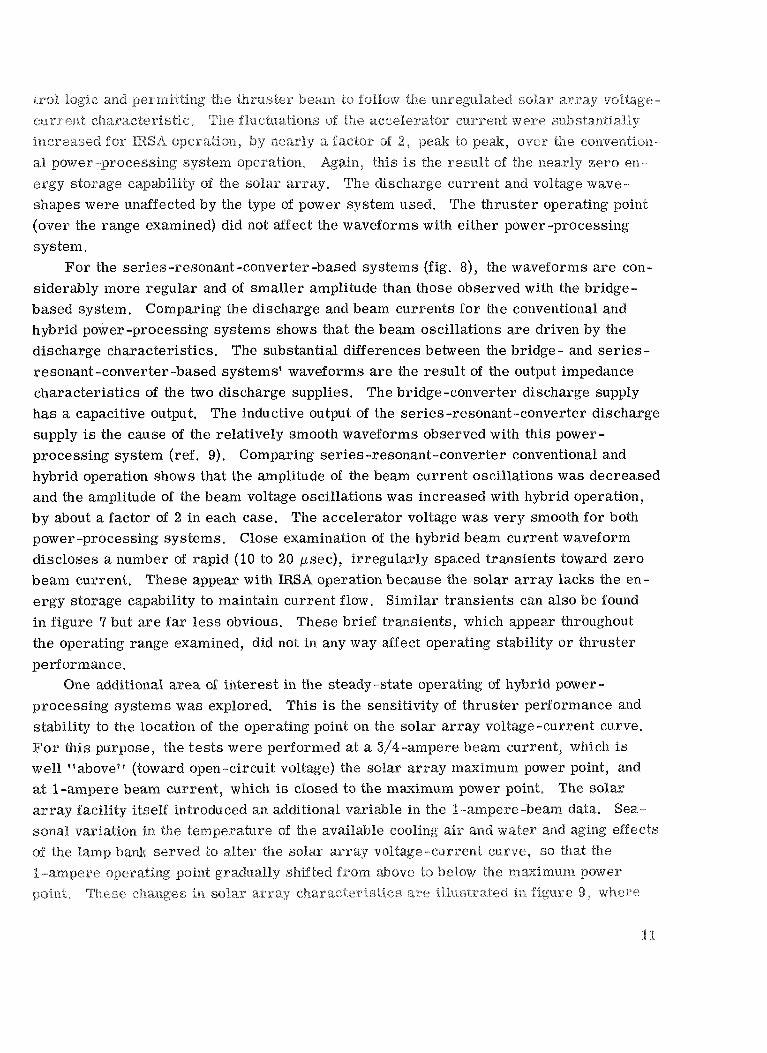
s y s tem . o r the series-resonant-converter -based systems (fig. 8), the waveforms are con-
siderably more regular and of smaller amplitude than those observed with the bridge- system. Comparing the discharge and beam currents fo r the conventional and
hybrid power-processing systems shows that the beam oscillations are driven by the discharge characteristics. The substantial differences between the bridge - and se r i e s - resonant-converter -based systems' waveforms are the result of the output impedance characteristics of the two discharge supplies. The bridge -converter discharge supply has a capacitive output. The inductive output of the series -resonant-converter discharge supply is the cause of the relatively smooth waveforms observed with this power- processing system (ref. 9). Comparing series-resonant-converter conventional and hybrid operation shows that the amplitude of the beam current oscillations was decreased and the amplitude of the beam voltage oscillations was increased with hybrid operation, by about a factor of 2 in each case. The accelerator voltage was very smooth for both power -processing systems. Close examination of the hybrid beam current waveform discloses a number of rapid (IO to beam current. se appear with
lity to maintain current flow. in figure 9 but ar less obvious. the operating range examined, did not in any way affect operating st
ec), irregularly spaced transients toward zero operation because the solar a r r ay lacks the en-
imilar transients can also be found
ility o r thruster rief transients, which appe
e a ~ d i ~ i o n ~ ~ area of inte est in the steady-state operating of hybrid power - processing systems was explored. his is the sensitivity of thruster pe

location of its operating point on the solar a r r ay voltage-current curve.
Perveance
The perveance of ‘the thruster grid system was examined, and the perveance limit voltage was determined for the conventional bridge and IRSA/bridge hybrid power- processing systems. To maintain satisfactory ion focusing, the operating total grid vol- tage should be well above the perveance limit. Therefore, it is important that the power system and the thruster do not interact i n such a manner that the perveance limit vol- tage is increased. Perveance limit voltage were determined a t discharge losses of 185, 200, and 215 electron volts per ion. At a given thruster operating point, the perveance curves were taken alternately with both systems. A full set of perveance curves is shown in figure 10, which plots accelerator impingement current as a function of total grid voltage difference. The perveance limit voltages (defined at the 45’ tangent point, which corresponds to a slope of A/V) a r e listed in table UP. A the table, the perveance limit voltage is slightly, but consistently, low hybrid power- processing system.
Integrally Regulated Solar rray/Thruster Transients
The behavior of the beam and accelerator A’s was examined during recovery from induced beam short circuits (arcs). Spontaneous a r c s in a well-conditioned thrust- er a r e infrequent. However, they do occur and the power system must be erate and extinguish them to prevent both damage to the power supplies an erosion of the thruster grids. solar array is inherently tolerant of load single difference betwe to a direct short

second. This provided a good view of a slightly different type of a r c recovery. In this event the beam recovered quite smoothly, but the accelerator voltage displayed a large number of rapid transients. However, even during this period the accelerator voltage had recovered sufficiently to decouple the neutralizer electrons, and the a r c extinguished at D. F o r all a r c s observed during this test, the recovery of the I operating voltage required between 200 and 300 microseconds.
A's to near normal
e PNG s
System tests were pe ormed in which two integrally regulated solar a r r a y s ( were used to directly power the beam and accelerator loads of a 30-centimeter-diameter, electron bombardment, mercury ion thruster. Two different conventional thruster power-processing systems were used to supply the remaining thruster loads, in effect forming two types of -hybrid power -processing system. he steady-state perfor - mance of the thruste hybrids and the totally conventional power -processing systems over a range of emission and magnetic baffle currents.
asured at 3/4- and I-ampere beam currents for both the
e waveforms of the major electrical parameters e r e recorded f o r all four power-processing combin
A/bridge hybrid, series-resonant converter, and transistor bridge conve
perveance limit voltage of the thruster grid system was determined for the hybrid and conventional power -processing systems. ehavior of the
om induced beam short ci s ) was e x a ~ i n e d . Throughout the testing sequence, the thruster operated efficien
vaporizer control with any of the fou ocessing systems.

creased further (high voltage and/or current), the efficiency of the thruster hybrid power-processing system would gradually approach that of the IRSA beam power supply itself, 99.9 percent.
served in the steady-state waveforms of the major electrical parameters. The striking differences observed between the bridge- and series- resonant- converter-based power- processing systems were traced to significantly different output impedance character- ist ics of the two discharge power supplies.
4. Comparing the perveance l imit voltages for the hybrid and conventional power- processing systems shows a slight, but consistent, improvement in operating m a g i n with the hybrid systems.
duced a r c recovery shows that the solar a r r a y s recover to normal operating voltages in approximately 200 microseconds after the precipitating cause of the a r c is removed. Continuous a r c s at a beam voltage of about 150 volts can be produced under off-normal operating conditions, such as low mode o r excessive tank pressure.
In conclusion, the basic characteristics of mercury ion thrusters and solar a r r a y s are extremely compatible. Using appropriately designed solar a r r a y s to directly power major thruster loads will produce stable, highly efficient power-processing systems for ion thrusters.
3 . Only minor differences between the hybrid and conventional systems were ob-
5. Examining the transient behavior of the beam and accelerator IRSA's during in-
Lewis Research Center, National Aeronautics and Space Administration,
Cleveland, Ohio, March 23, 1977, 506- 23.
REFERENCES
I. Triner, James E. : A
-

7. Collett, C. : Thruster Endurance Test. (Hughes esearch Lab. ; CR-135011, 1976.
8. Biess, J. J. ; and Inouye, L. Y. : Breadboard Power Supply, Part No. 283213, Defence and Space Systems, 1975.
o c u m e n ~ t i o n of the ~ n g ~ e e ~ i n g
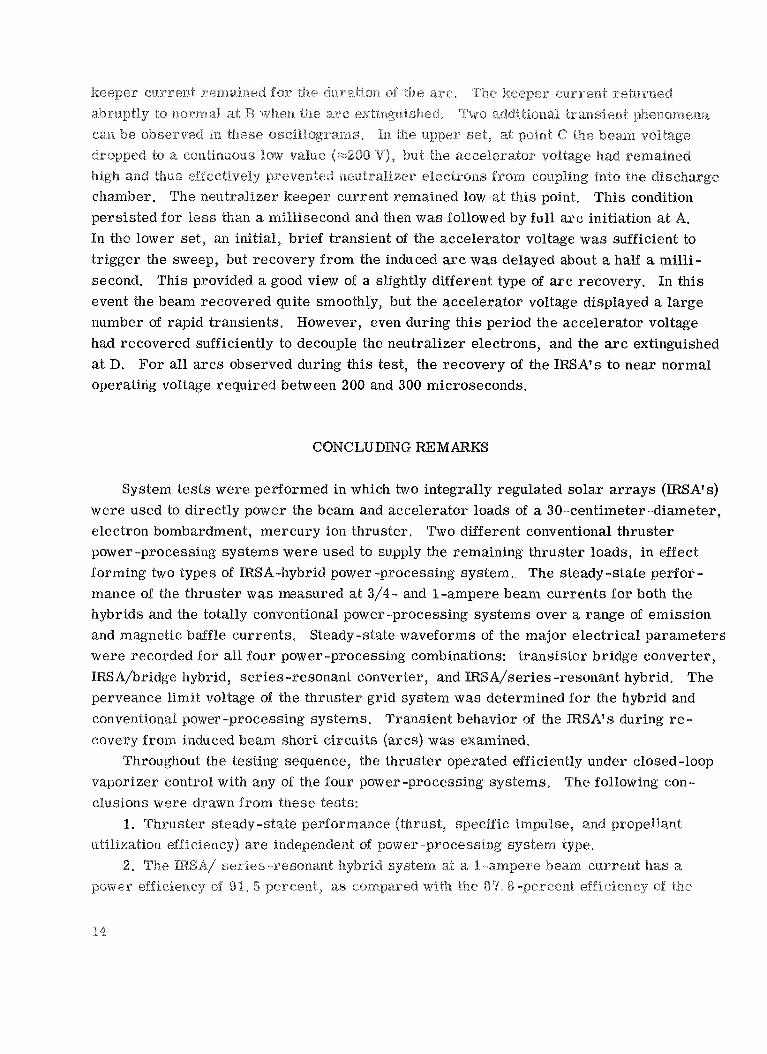
TABLE - MATRTX O F OPERATING POINTS EXAMINED WITH VARIOUS POWER-PROCESSING
SYSTEMS DURING STEADY-STATE PERFORMANCE TESTING
Emission a current ,
A
3.95
4.30
4.60
5.30
5.70
6 .15
Magnetic baffle
b current, A
2 .0 2.5 3.0
2 .0 2 .5 3.0
2.0 2.5 3.0
2.0 2.5 3.0
2.0 2.5 3.0
2.0 2.5 3.0
Power-processing system
Transistor bridge converter SCR series-resonant converter I
Conventional IRSA hybrid Conventional
X X X X X X
IRSA hybrid
X X X
%ischarge voltage was maintained at 35 V throughout. bMagnetic baffle has 10- turns. 1
2

GG
[Magnetic baffle current, 2. 5 Ad
-500 3 . 4
35 4.30
7 . 5 1 . 0
1 6 . 8 2.13
0.683 0 .154 0.048
47.4 2626
0 .791
Parameter
-500 3 .2
35 4.60
7.2 1.0
16.8 2.10
0.648 0.169 0.045
47.4 2696
0.812
Beam (screen) voltage, V Neutralizer coupling voltage, V Accelerator voltage, V Accelerator current, mA Discharge voltage, V Emission current, A Cathode keeper voltage, V Cathode keeper current, A Neutralizer keeper voltage, V Neutralizer keeper current, A
Discharge
Main vaporizer flow rate, A Cathode vaporizer flow rate, A Neutralizer vaporizer flow rate, A
Perveance limit voltage, V
Ideal thrust, mN Ideal L Is,iric impulse, sec Measured propellant utilization efficiency
loss, eV/ion
0.70 I 1 . 0 0
IRSA hybrid Conventional
185
1100 -11 .5 - 500
3.6 35
' 95 7.9 1 .0
16 .0 2.12
0.807 0.137 0.043
'50.7 a2523
'0.760
Discharge loss, eV/ion
a Beam current, 0.75 A.
TABLE III. - PERVEANCE LIMIT VOLTAGE
FOR IRSA-HYBRID AND CONVENTIONAL
185
1100 -11.2 - 500
2 .8 35
5. 30 7.0 1 . 0
16 .0 2.12
0.960 0.163 0.043
67 .7 2849
0.858
200
1100 -11.0 - 500
2 .8 35
5.70 6 . 9 1 . 0
15.7 2.12
0.960 0.169 0.040
67.7 2839
0 .855
215
1100 -10 .7 - 500
3 . 0 35
6 .15 6 . 7 1 . 0
15.6 2 . 1 2
0.949 0.174 0.043
67 .7 2849
3.858

Solar array: Regulated section, sized for end of life, maximum temperature, and maximum load
Unregulated section, sized for beginning of life, m in imum temperature, and min imum load
-L- + Regulation switches
isoletion
Load
Figure I. - Block diagram of an integrally regulated solar array.
Figure 2. - 1-Kilowatt laboratory solar array facility with one UI uit: i i i i i e rnuclules opened to display array panel and lamp bank.

Thruster common
Accelerator
Accelerator gr id
+- - -
_I
250 v
Regulation
80
40
160 V
80 V
40 V
160 V
V
V
20 v
10 v
Switch dr ive unit
Sensed vo l tage7
r------
Solar array
Figure 3. - IRSA accelerator supply (-500 VllOO mA).
Solar array sections
-Sensed voltage
Figure 4. - IRSA beam supply (1100 VIA).

Figure 5. - Regulator block diagram.
- _ -
- - _ _ _ _ _ _ _____I_--
Figure 6. - Interconnection circuits between thruster, solar arrays, and conventional power supplies.

J E , ~ 2 cm
(b) Hybrid. (a) Conventional Figure 7. - Selected steady-state waveforms for conventional bridge and IRSA/bridge hybrid power-processing system operation.
VI, 500 V/cm
0
VA, 500 V/cm JB, 1 A/cm
JE, 4 A/cm 0
0 (a) Conventional. (b) Hybrid.
Figure 8. - Selected steady-state waveforms for conventional series-resonant andIRSA/series-resonant hybrid power- process ing system operation.

ei a r m
9 800-
600
400
l . ~ 1.8
4 +\ 0 Normal operating points A Auxiliary test points
-P-- Unregulated (cold, new lamps) --- Unregulated (hot, old lampsl ~ Regulated
\ \ \ ' \ \
\ \ \ I
-
I
A Conventional 0 IRSA hybrid 4 Point at which
perveance limit voltage was read
4 (a) Discharge loss, 215 eVIion. 2.0r
m
- (b) Discharge loss, 200 eVIion.
800 900 1000 1100 1200 Total g r i d voltage, V
(c) Discharge toss, 185 &/ion.
Figure I O . - Thruster gr id perveance current- ivolfaqe curves (at i-ampere beam current).

’9
’9
-l