search.jsp?R=19710003012 2018-11-09T02:25:41+00:00Z · ABSTRACT...
59
https://ntrs.nasa.gov/search.jsp?R=19710003012 2018-12-02T09:58:46+00:00Z
Transcript of search.jsp?R=19710003012 2018-11-09T02:25:41+00:00Z · ABSTRACT...

https://ntrs.nasa.gov/search.jsp?R=19710003012 2018-12-02T09:58:46+00:00Z

CODEIDENT.NO. 81205
NUMBER, D2-118341-1
• DRL88 (T-587) ....
TITLE:_ SNEAKCIRCUIT,,ANALYSIS HANDBOOK I i ml •
'b
I I
II l III I I I III I II I I II L
MODEL APOLLO CONTRACT NA_g-10364 .. ::,IS_
ISSUENO., .... ISSUEDTO: .........
iJ
PREPAREDltY_p.:Rankin: .'kko 7PREPAREDBY__, t• cs.SUPERVISED
• . A"PROVEDeV_
' ii
1 I)2-118341-I
1971003012-TSB03

REVISIONSJ _1 I I I I I
R_.s.y..M. DESCRIPTION DATE APPROVED _t i t lJi
o
2 92-118341-1
;,iJ,i,,m_.s-.a4(L_dl _ oo/_ adrf
1971003012-TSB04

ABSTRACT
The conceptsof formalengineeringanalysisto detect,and thusprevent,sneakcircuitsare pre.sented.Sneakcircuitsare
" commonlyknownas system"glitches"or electricalanomalieswhichare not contingenton componentfailures. It has beenfoundthatsuchsneakcircuitshavedistinct,classifiable
, " characteristicswhichmakeengineeringanalysisfeasible. ." Thesecharacteristicsand methodsfor theirrecognitionare
disclosed herein.
KEY I_ .....
SneakCircuits
Pathfinding
Circuit Topology
Elec'_rical/Electronic Analysis
ComputerizedElectricalSystemAnalysis ;_;_iApollo SpacecraftAnalysis ii_ii_i
Topological Analysis .NetworkTrees .,.
NodeTopographs
...... -. T T0D " ";
TABLEOF CONTENTS
SECTION PAGE
REVISIONS 2
ABSTRACT 3
• KEYWORDS 3
IABLEOF CONTENTS 4 - 5• ILLUSTRATIONS 6
REFERENCES 7 - 86
1.0 INTRODUCTION 9t
1.1 BACKGROUND 9
1.2 PURPOSE 10- i
1.3 SCOPE 10 ....
2.0 THEORYOF ANALYSIS 12
2.1 SNEAKCIRCUITDEFINITION 12
• 2.2 SNEAKCIRCUITEXAMPLE 12 i
2.3 CLASSIFICATIONOF SNEAK_CIRCUITS 13 i2.4 ANALYTICALTECHNIQUE 14 )
• 2.5 NODETOPOGRAPHS 16 _
2.6 SNEAKCIRCUITCLUES 17 )"
2.6.1 Power-to_-PowerPath 17 _l......
2.6.2 Ground-to-GroundPath 18'I
2.6.3 ReverseCurrentFlow 18
2.6.4 MultipleControls lg• 2.6.5 Relay Race 20
2.6.6 AmbiguousIndicators 20
.- 2.6.7 Misleading Labels 21
3.0 APPLICATIONOFCONCEPTS 22
3.1 DATA ' 22
3.1.1 Data Requirements 22
3.1.2 Data Control 24
3.2 SYSTEMPARTITIONING 24
• 4 I)2-t18341'-1
1971003012-TSB06
/
SECTION PAGE
: 3.2.1 UpperPowerTree 25
_, 3.2.2 PrimaryPowerand Control 25 ....
3.2.3 SecondaryPowerand Control 25
3.2.4 SignalCircuits 25
3.3 NETWORKTREES 77
._ 3.4 TREEANALYSIS 29P
3.5 SNEAKCIRCUITANALYSISREPORTING 30
i_ - 3.6 COMPUTERASSISTANCEIN SNEAKCIRCUITANALYSIS 31
i: 3.6.1 AutomatedFiling_Program 31i ....
'1
•. 3.6.1.1 AFPMasterfileInformation 31
3.6.1.2 AFPReports 32
3.6.2 AutomatedSneakProgram(ASP) 33 ....
3,6.2.1 ASP Inpu1:s 33 ....
3.6.2.2 ASPProcesses 34
3.6.2.3 ASPReports 34
3.6.2.4 ASP Tree-SketchingProcedure 36 -,
3.6.2.5 AdditionclASP Capabilities 38 "C
3.7 SUMMARYAND CONCLUSIONS 42 _"]
!APPENDIXA. APOLLOBID INPUTGUIDELINES 45
0_
*
5 02-118341-1
1971003012-TSB07
ILLUSTRATIONS
FIGURE •TITLE PAGE
2-I OriginalSneakCircuitExample 13
. 2-2 Exampleof NetworkTree 15 .....
2-3 ElementaryNodeTopographs 16
. 2-4 "H" Topograph/ReverseCurrentDome 16
' 2-5 Power-to-PowerSneak 17
.. 2,6 Ground-to-GroundSneak 18
2-7 ReverseCurrentSneak lg
• 2-8 MultipleControlSneak Ig
2-g RelayRaceSneak 20
2-10 Amblguous.IndicatorSneak 20 ....
2-II Mlsleading Label Sneak 21
3-I Exampleof SystemPartitioning 26
3-2 Elementary Trees 27
3-3 TypicalTree 28
3-4 "Mode Diagramsof Tree 29
3-5 InterrelatedNetworkTrees 30
3-6 High ImpedanceSub-TreePartitions 37 _..
3-7 Umbilicals on Tree 37 .,i_,,3-8 LoadSymbolsfor Tree Sketches 39 .
3-g SneakCircuitAnalysisWo_k FlowDi-agram 44
A-1 BID InputSheetwith TypicalBI and B2 Entries 46 ._
A-2 I11ustrationof ShortingSwitch 52 ,
" A-3 Double-Pole,Double-ThrowGangedSwitch 53 ._.
_ A-4 Load Codtng Example 54 .,_.i4
" A-,5 Coding of Parallel Branches 56
. A-6 Arc-Suppressed Relay Coil 57
6 02-118341-I
1971003012-TSB08
w
-_ REFERENCES
.iI, '.bOl_-P-OI8,"Plan,ApolloSpacecraftSneakCircuitAnalysis",
ContractNo. NASW-1650,NationalAeronauticsand Space. Administration.
P.. b_t-llBOBI-2B_"Requirementsfor the AutomatedSneakProgram"- The" BoeingCompany.
3. D2-118211-1A,"AutomatedSneakProgramSystemDocument/AutomatedSneakProgram(ASP)"- The BoeingCompany.
4, DP.-IIB212-1,"BIDPreprocessor/AutomatedSneakProgram(ASP)"-The BoeingCompany.
J 'o
5, U2-I18213-I,"NorthAmericanPreprocessor/AutomatedSneakProgram,, (ASP)"- The BoeingCompany.
- The• "GSEPreprocessor/AutomatedSneakProgram(ASP)", 6. bZ-llB214-1,
: BoeingCompany.
Y, UZ-I18215-I,"GrummanPreprocessor/AutomatedSneakProgram(ASP)"-The BoeingCompany.
8, D2-I18216-I,"GrummanPre-Preprop/AutomatedSneakPrograln(ASP)"-The BoeingCompany.
! g. 02-118217-I,"BEDUpdate/AutomatedSneakProgram(ASP)"- The Boeing ....Company.
10. D2-118218-I,"InlineDisconnect/AutomatedSneakProgram(ASP)-The BoeingCompany. "'
• 11. D2-I18219-I,"MergeBID/BED/AutomatedSneakProgram(ASP)"- The _.. BoeingCompany.
_ 12, DZ-I!B220-1,"Branch/CrossReferenceTable/AutomatedSneakProgram
i_ (ASP)"- The BoeingCompany
13. D2-118221-1A,"PathDerivation/AutomatedSneakProgram(ASP)"- The• BoeingCompany.
• 14. D2-118222-1A,,,Regeneration-I/AutomatedSneakProgram(ASP)"- The" Boeing Company,
Q :!'
" 15, D2.118223.1A, ,,RECFIX/AutomatedSneakProgram(ASP)"- The BoeingCompany.
i
7 B2-I18341-I
°_°:_ 1971003012-TSE

16. DZ-118225-1A,"LegalPathReport/AutomatedSneakProgram(ASP"-The BoeingCompany,
17. D2-118226-1A,"NodeReportDataGeneration/AutomatedSneakProgram• (ASP)"- The BoeingCompany,
18. D2-118227-1A,"Intersectand SpecialNodeReportand ControlSummary, . Report/AutomatedSneakProgram(ASP)"- The Boeing
Company.
Ig. D2-118228-I,"ISAMTableGenerator/AutomatedSneakProgram(ASP)"-The BoeingCompany•
Q
20. D2-118305-1, "Path Redundancy/AutomatedSneak Program (ASP" -Tbe:..Boeing Company•
21. D2_118306-I,"PathRedundancy-I/AutumatedSneakProgram(ASP)"-The BoeingCompany.
22. D2-118307-I,"IntersectNode/AutomatedSneakProgram(ASP)"-The BoeingCompany• :
23. D2-118308-1,"SneakUtilityPrograms/AutomatedSneakProgram(ASP)"- The BoeingCompany•
24. DZ-11830g-1, "O/ode/Load-Special Node/AutomatedSneak Program(ASP)"- The BoeingCompany• _..
" The Boelng25. D2-1i8243-1, "AutomatedFiling ProgramRequirements, -Company.
26. D2-11820g-1, "Automated Filing Program (AFP)," - The Boeing Company.
' . 8 ' 02.,118341-1
......... _- 1971003012-TSB10
l.O INTRODUCTION
, This handbookdescribesa sneakcircuitanalysismethodandits applicaLionto electricalor electronicsystems. It isintendedfor use in initiatinga sneakcircuitanalysis
. task. If tileanalysisis to be aidedby automatedcircuitpath tracing,thenthe handbookshouldbe usedin conjunction
, with the referencedcomputerprogramdocuments.
,. The handbookis dividedintothreesections, lhe introductorysectiongivessomeof the historyof Apollosneakcircuitanalysisand scopesthe typesof circuitsto which the-ana-
• lysishas beenapplied. In the next section,Theory,asneakcircuitdefinitionand ensuingdiscussionleaddirectlyto someexamplesof knownsneakcircuits. Also describedis a methodof reducingsystemcomplexityto achieveselec-tivelossof detailfor analyticalpurposes.A new technique,topologicalrecognition,and its use as an analyticaltoolisdiscussed,and the sectionis concludedwith recognitioncluesto assistthe analystin searchingfor sneakcircuits. ......
The sectionentitled"Application"relatesthe detailsof ..sneakcircuitanalysisbasedon Apolloexperiencebut isintendedfor generalapplicationto any electricalorelectronicsystem. Schematicdatasystemsand trackingof ,__changesto assurecurrentconfigurationsare discussed.Datareductionto producenetworktreesand,subsequently, .....nodetopographsis illustrated.Analysisof systemoperating ....,.modesand applicationof sneakcircuitcluesis described.The sectionis endedwith a descriptionof a new automatedmethodof tracingthroughschematicinformationto find ......
....._,,_,,,,.: circuitpaths--perhapsthe most significantadvancein_:.=_::_, : computerapplicationto electrical/electronicschematic,.:_,,,_,.,.. information processing.
_'_,_'_ ._
',,,-_,_.-,:.,::::_._:.... • Duringthe ApolloLunarLandingProgram,officialsof the ,I:,I,__!IC::,:; NationalAeronauticsand SpaceAdministrationat theManned
_,ii,_:ii;!%_.,,. " SpacecraftCenterin Houston,Texas,recognizedsneakcircuits _,",,T,_,::_:,• as a latenttypeof electricalhardwaredeficiencywhich':/_:_ii:!-i;_:.i;:! coulddestroycriticalequipmentand endangerthe astronaut _ _
., __ ........
_ 9 O2-118341-1
_ o
1971003012-TSB11

crew. Accordingly,a sneak circuit analysis task was imple--mented on Apollo in early 1968. A team of electricalandelectronicanalystsand data processingspecialistswasassigned the task of identifyingsneak circuits in the Apollospacecraft. An additionalgoal establishedat the outsetwas to automate as much of the analysis as possible to re-move human error and expedite results.
•. To date, the analysis has uncoveredover 60 sneak circuits,most of which could be preventedby crew proceduralchanges.In addition,an operationalcomputerprogram was developedto automaticallysearch out circuit paths, thus eliminating
" the burdensomeand costly task of tracing from one schematicpage to the other in order to complete a circuit. As a by-product, many schematicerrors have been found through theuse of this program.
The material containedherein is based wholly on the experi-ence gained during the first two years of performingtheApollo sneak circuit analysis task.
1.2 Purpose
This handbook has been prepared for the sole purpose ofmaking availableto all agencies the experienceand techni-ques gained from analysis and developmentof sneak circuittechnologyon Apollo. It is primarily intended for thesneak circuit task manager and providesan overall,yet de- - v..
. tailed, descriptionof the sneak circuit analysismethodand its applicationto electricalor electronicsystems.Further, it gives a baseline descriptionof the Automated .Sneak Program (a computerizedcircuit path finder) which,in conjunctionwith the referencedcomputer documents,maybe used to initiatea computer-assistedanalysis. The hand-
book may also be used by the analyst to get a clear under- _" standing of what a sneak circuit is and how to find it.
1.3 Scope .-
The scope of the handbook Includesa detailed descriptionof ii
the theory, data, and methods requiredto perform a sneak ,i!circuit analysis. It emphasizessneak circuit identifica-tion through the applicationof topologicalclues. A generaldescriptionof the AutomatedSneak Program is given.
110 D2-118341-1 '
1971003012-TSB13
The originalsneakcircuitanalysisplan (ReferenceI)identifiedtwo typesof sneakcircuits;currentsneaksandsignalsneaks. This handbookdealspredominatelywith cur-
" rentsneaksin powerand controlcircuitry.Applicationofthe methodsto digitallogiccircuitsof computersis notthe subjecttreatedhereineven thoughin somecaseslogic
• gatesand otherlogicelementsare includedas circuitcom-ponentsinitiatingor inhibitingcontrolfunctions.
<
11 02-118341-1 ,:

2.0 THEORYOF ANALYSIS
This sectiontreatsthe theoreticalaspectsthatevolvedduringthe courseof analysisfor sneakcircuitson Apollo.
. At the outsetof the analysis,not evenan accuratedefini-tionof a sneakcircuitexisted. Later,a generallyaccepta-ble definitionand somecluesfor findingsneakcircuits
• were established.The clueswere foundempirically,Forexample,it was notedthatlatentcircuitpathsresultingfromunusualswitchconfigurationswhichconnectedtwo or
• more powerbussesor powersourcestogether,oftenled tosneakcircuits. In addition,switchingmodesthatallowedcurrentreversalthroughone branchof a circuitoften
• causeda sneakcircuit. Thesecluesand othersnotedbelowwere analyzedin and of themselves.The resultled directlyto the followinganalyticaltheory: Electricaland electroniccircuits,no matterhow interconnectedand interrelated,canbe topologicallysimplifiedusingselectivelossof detail,untilcertainsneakcluepatternscan be easilyrecognized.Analysisof circuitoperatingcharacteristicsin the patternis usedto determinesneakcircuitp¢obability.
As detailedlaterin thissection,somelatent anomalouscircuitconditions_donot resultfromsneakcurrentpathsbut ratherfromincorrectcircuittiming,falselabelsoncontrols,and ambiguousor falseindicationsof statuson in_tersand otherreadoutdevices. Experiencehas shownthattheselatentconditionsare alsomoreeasily uncoveredusing _topologicalsin@lification. -,/
2.1 SneakCircuitDefinition
A sneak circuit ts deftned as a path that has a latent ianomalouselectrical condition resulting from an unapparentstimulus-response relationship, which causes an unwantedfunctlonor Inhlbltsa wanted function. It shouldbe
i|- noted that the electrical condition tncludes not onlyelectrical and electronic eiements but aiso tnvolves asso- !ctated operator observations and resultant acttons.
2.2 SneakCircuitExample
" The originalexampleprovidedby NASA to illustratea sneakcircuitshowshow an apparentlyInnocent-lookingcircuit
12 .... 02-118341-1
1971003012-TSC02
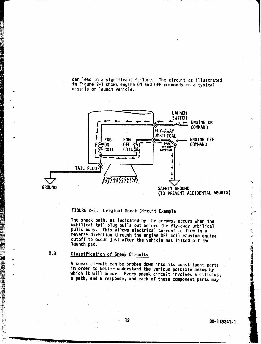
can leadto a significantfailure. The circuitas illustrated ....in Figure2-I showsengineON and OFF commandsto a typicalmissileor launchvehicle.
LAUNCt4SWITCH TII:
r "- _- d,- 4-,-- _.. 4- ,- ENGINEON6 COMMAND
I FLY-AWAYUMBILICAL
• ENG ENG o---- ENGINEOFFON OFF C" "_ "" COMMAND _!:_
COIL cOIL 'i sw,.rcNm mmmm
GROUND SAFETYGROUND _•(TO PREVENTACCIDENTALABORTS) ....
FIGURE2,1. OriginalSneakCircuitExample Z,"_"
The sneak path, as indicated by the arrows, occurs when the .....umbilical tail plug pulls out: before the fly-away umbilicalpullsaway. This allowselectricalcurrentto flowin a "_reversedirectionthroughthe engineOFF coilcausingengine _cutoffto occurjustafterthe vehiclehas liftedoff thelaunch pad, .
o
2.3 .Classt.f.ication of SneakCircuits
. A sneakcircuitcan be brokendownintoits constituentpartsin orderto betterunderstandthe variouspossiblemeansby
• w_Ich it will occur. Everysneakcircu;tinvolvesa stimulus, ,a path,and a response,and eachof thesecomponentpartsmay
i
• 13 D2-1,16341-1o _VQ
-- _-- Q
"197"10030"12-TSC03

be the initiatorof an unintendedactionor function. Thestimulican be manualor automaticand includesuchactionsas switchoperations,relaytransfers,logicenables,etc.
" Pathsalwaysincludeelectrical-electronicelementspermit-ringelectricalenergyflowbut may also requireassociatednon-electricalenergyformsfor completion. Responsesin-
" cludeindicationsas wellas subseque,,tfunctionswhichinturnmay act as stimuli. Thus,a sneakcircuitdrivinganindicator,say an abortlight,can causean unnecessarysubsequentactionwhichmay have far-reachingconsequences.
Sneakcircuitsmay be _.lassifiedintofourcategoriesas anaid to analysis.The fourcategoriesare basedon differentsneakconditionswhichmay existas follows:
I. SneakPath - A sneakpathmay causecurrentor ....energYto flowalongan unexpectedroute.
\,
2. SneakTiming- Sneaktimingmay causecurrentorenergyto flowor inhibita functionat an un-expectedtime.
3. SneakIndication- A sneakindicationmay causean ambiguousor falsedisplayof systemopera-tingconditions.
4. SneakLabel- A sneaklabelmay causeincorrectstimulito be initiated. _ .......
,)
2.4 AnalyticalTechnique%
The basisof the sneakcircuitanalyticaltechniqueis topo- ilogicalsimplificationof circuitryto facilitatecluepat- ilternrecognition.Thus,the"firststep requiresthatthesystemand.detailelectricalschematicsbe simplifiedto 1basiccircuitcontinuitiesshowingpowersources,nodes, j
" switches,diodes,loads,and grounds. The circuitelements (, and interconnectionsare drawnin the formof a networktreeusingselectivelossof detailto showonly the impor-
• rantelements. The resultantsketch is not place-oriented. as are_mostschematics.All extraneousinformationis
omittedincludingwiringdata,componentnomenclature,
14 D2-118341-1
1971003012-TSC04
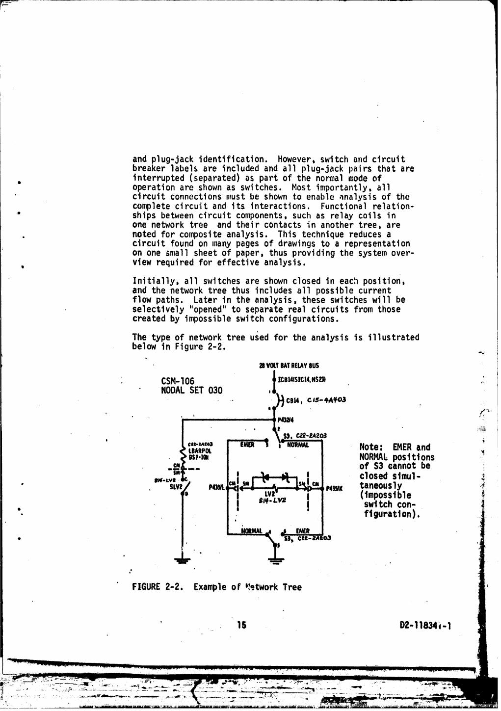
and plug-jack identification. However, switch and clrcuttbreaker labels are included and all plug-jack pairs that areinterrupted (separated) as part of the normal modeof
• operationare shownas switches.Most importantly,all' circuitconnectionsmustbe shownto enableanalysisof the
completecircuitand its interactions•Functionalrelation-" shipsbetweencircuitcomponents,suchas relaycoilsin
one networktree and theircontactsin anothertree,are• notedfor compositeanalysis. This techniquereducesa
circuitfoundon many pagesof drawingsto a representationon one smallsheetof paper,thusprovidingthe systemover-view requiredfor effectiveanalysis.
Initially,all switchesare shownclosedin each position,and the networktreethusincludesall possiblecurrentflowpaths. Laterin the analysis,theseswitcheswill beselectively"opened"to separaterealcircuitsfromthosecreatedby impossibleswii:chconfigurations.
The typeof networktreeused for the analysisis illustratedbelowin Figure2-2.
a vm.Teatneuweusi
CSM-106 _Ice==srcl4,NS_ /NODALSET030 ,L
r
m _
. ql ,p_,_,
. I _ _ S). CZ_-tA20_I ;
NORMAl,post tt ons _.c_ " of S3 cannot be ;IM I _:. I i closed stmul-
" $LV P4)tL N)_I( taneous ly 4I I (impossibleI sJ,e.Lv= I swttch con-
", ' ' figuration).
_mnmL.4J E_ i• , _.IIi-$IIIiell- IAIO,_
oe
FIGURE2-2. Exampleof _-.twork Tree
• ,_ 1S D2-11834:;t- 1
__,_,, PJ:_°_:!!_7':L-_,.-,- ' ........ I " " _ llllllll I _J= _L I I [ _ .........L_,]_L_._ ._----_..' .:._..--.=--- ._-..--_ ,.,. _, -_,- .,-._ _ _ -_ ..... ;_. , ._=- .--_- ...... _ __ -..... . ;.... _ ..... "
1971003012-TSC05
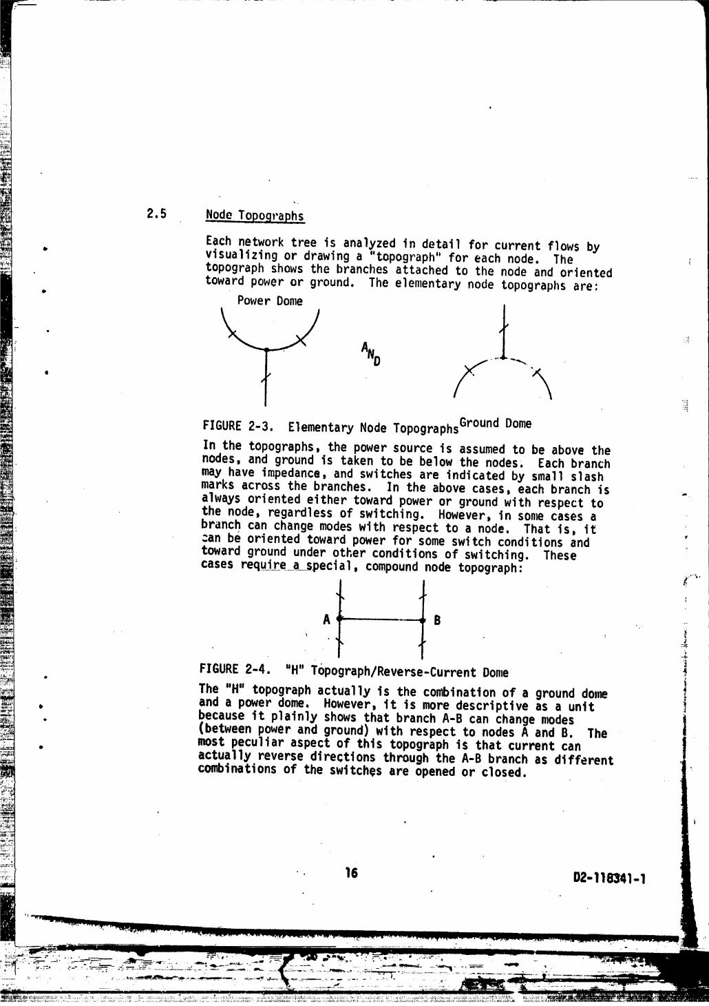
2.5 .Node..TopograPh.s
Each network tree is analyzed in detail for current flows by° visualizingor drawinga "topograph"for eachnode. The
topographshowsthe branchesattachedto the nodeand orientedtowardpoweror ground. The elementarynode topographsare;
° PowerDome
t'T!:_
_:._
FIGURE2-3. ElementaryNodeTopographsGr°undDome
In the topographs,the powersourceis assumedto be abovethenodes,and groundis takento be belowthe nodes, Eachbranchmay haveimpedance,and switchesare indicatedby smallslashmarksacrossthe branches. In the abovecases,eachbranchisalwaysorientedeithertowardpoweror groundwith respecttothe node,regardlessof switching.However,in sonmcasesabranchcan changemodeswith respectto a node. That is, itcan be orientedtowardpowerfor some switchconditionsandtowardgroundunderotherconditionsof switching.These
casesrequirea special,compoundnodetopograph: _..,,,.
A -- B ". 7,
• • ; AI
FIGURE2-4. "H" Topograph/Reverse-CurrentDome
• iThe "H" topograph actually is the combination of a ground dollmand a power dome, However, it is more descriptive as a unit
" becauseit plainlyshowsthatbranchA-B can changemodes j• (betweenpowerand ground)with respectto nodesA and B. Themost peculiaraspectof thistopographis thatcurrentcan
" actuallyreversedirectionsthroughthe A-B branchas differentcombinationsof the switchesare openedor closed.
15 D2-I18341-I
The elementaltopographspresentedabove are quite simple,perhaps deceptivelyso. The techniqueof breaking up atree into its componentnode topographsis a powerful tool
• for analysisof even the largest of network trees. It pro-vides an orderlymethod of accountingfor all current flowswithout getting lost in complexity. Each node topooraph is
= thereforean analysis key for applicationof sneak circuitclues against the network tree. Multiple branches comprisin!'jeach part of a node topographmust be applied individually
• and in combinationin the patterns• The sneak circuit cluesdiscussedin the followingsection are centeredaround re-cognitionof the topology presentedabove.
2.6 Sneak, CircuitClues
The clues given in this section are to be applied against _:the network trees by using the node topographsandsystem operationknowledge• Generally,each node topographis to be located in the tree and used as the baseline fromwhich to check for any possible problems. The problemswillfall into one or more of the sneak circuit categories:sneak path, sneak timing, sneak indication,or sneak label.
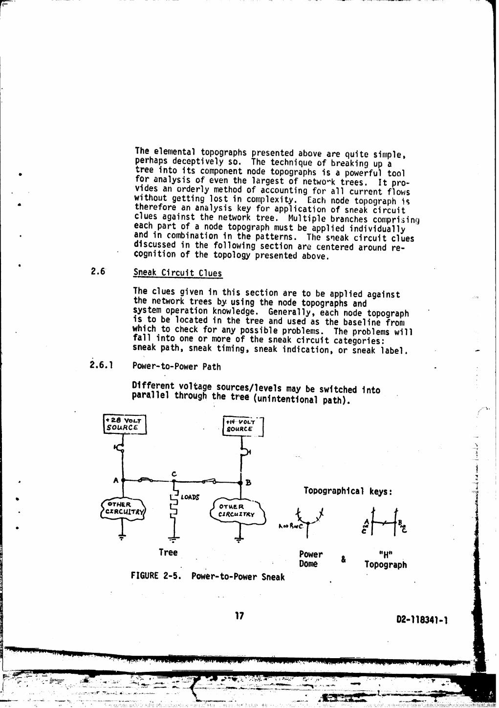
2.6.l Power-to-PowerPath
Different voltage sources/levels may be switched tntoparallel through the tree (unintentional path).
+I@VOLT
s°ELt -RE_I I I
i
Tol}ographtcal keys: ....
ko_ R ..:w
o •
Tree Power & "H"Dome Topograph
FIGURE 2-5. Power-to-Power Sneak t
17 02-118341-i
The power domeprovides a low impedancepath to the 14 volt-differentialbetweenbatteriesfor someswitchconditionsin the aboveexample.
O
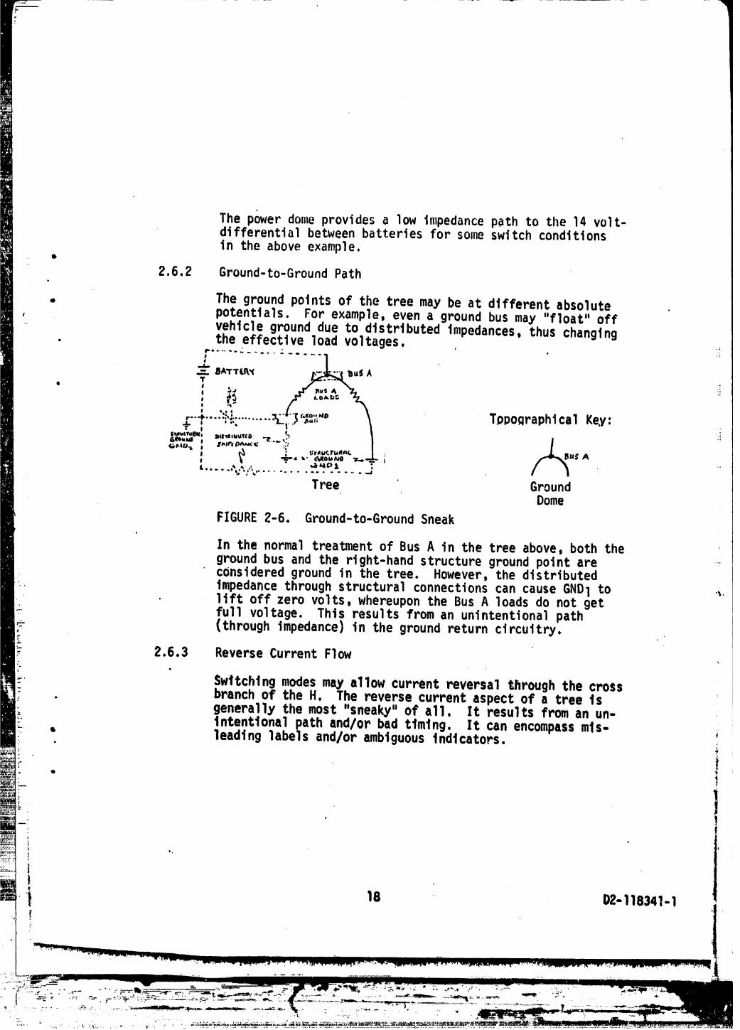
2.6.2 Ground-to-GroundPath
, The groundpointsof the treemay be at differentabsolute ., potentials.For example,evena groundbus may "f]oat"off- vehiclegrounddue to distributedimpedances,thuschanging
. the effectiveloadvoltages, , _;
r.............l
; r_ ,,r _o,.,, "-z.,,| ¢.i t _ ... ,r"¢....:i":.........._ iI'$:'_"" Tppoflraphical Key:
_" I a.. _ '&_lQ,.a.dl , .- ,!:,vAlillr/4_l_i s, IIIIIII6UTID _ . ,'
' _" ,._. s- C._ou_PO "a.o..-_._ L "*"
Tree GroundDome
FIGURE2-6. Ground-to-GroundSneak
In the normaltreatmentof Bus A in the treeabove,both thegroundbus and the right-handstructuregroundpointare ....consideredgroundin the tree. However,the distributedimpedancethroughstructuralconnectionscan causeGNDl to ._liftoff zerovolts,whereuponthe Bus A loadsdo not get
• fullvoltage. This resultsfroman unintentionalpath(throughimpedance)in the groundreturncircuitry.
r
:- 2.6.3 Reverse CurrentFlow
L Switching modesmay allow current reversal through the cross- branch of the H. The reverse current aspect of a tree t s
• generally the most "sneaky" of a11, It results from an un-_. Intentional path and/or bad ttmtngl It can encompassmls-
• leading labels and/or ambiguousIndicators. :m
Q
i
'_ 18 O2-118341-1!{
::"_"° ..... *-'_:_.... -....... _',_" :-- 1971003012-TSC08

The tree above represents the originalsneakcircuitexamplegiven in Figure 2-1. The "engine on" coil and the "enginecut-off" coil share a ground node at N1 through Umbilical 1.The design intent is for current to flow from N2 to N1 throughthe engine cut-off coil when the launch abort switch is in theABORTmode. A safety ground is provided through the switch toprevent accidental aborts from stray line voltages. However,if Umbtltcall opens before Umbilical 2, and if the launch abort
.... swttch is in the safety ground posit_on, then current will re-verse through the "H", going from N1 to N2 to ground. Thts maypick the engine cut-off cot1 and abort the launch unintentional-ly. Sucha sneak ctrcutt is a result of both an unintentionalpath and bad timing of the umbilical separations.
2.6.4 HultloleControls ,...
Simultaneous ogpostng.qomma.nd_ma_ be transmittedthrough control circu_tw in the tree.
i T
co,r_oc0,____...________f CONrRoLzo. I I . _ Topographical Key:
mr K...,Io_._
/Tree Power
. DomeFIGURE2-8 Hulttple Control Sneak
19 D2-118341-1
" 1971003012-TSC09

The motorswitchwillcyclecontinuouslyfor the switchingmodesshown• This is the resul_of too many independent
, controlsallowingthe possibilityof bad timingin theswitchoperations.
2.6.5 RelayRace
Relayoperation timi.ngmay generateincompatibiIitles.• The illustrationsglvenaboveconsis.tof conductedcurrent
paths,but the infiuenceof otherlinksmust be considered•For example,relaycoilsand theirassociatedcontactsw IIfrequentlybe foundin differenttrees,but the coil-to-
' contactrelationshipcan be thoughtof as a "functionalbranch"relatinothe two trees. In fact,thisis the approachusedto findrelayracesand other_bad timingresultscausedby the interactionof circuitelementsthatare not connected ....
' by hardwire. The functionalrelationbetweentreesand the ,equivalenttopographlcalrepresentatlonare Illustratedbelow.
-....... TopographicalKey:
Tree A TreeB "FunctionalH"Topograph _.
FIGURE2-g. RelayRaceSneak
2.6.6 AmbiguousIndicators
Attempts to monitor multiple modesor functions wtth a singleindicator endangers the fidelity of the status display.
• Topographtca1 Keys: i
Valve 1 Valve 2 _ _• Solenotd _- _Ind. "_ Solenoid
" " "H"Tree - Power &Dome Topograph
FIGURE2-10. AmbiguousIndicator Sneak '
20 !)2-11834i-1
.......... 1971003012-TSC10

The topographsand treeaboveshow thateither"switch"(solenoidcontacts)can allowpowerflowthroughnodetlt_ground. The treeillustratesthat Lhe lampwill indicatevalveclosurewhenevereithervalveis closed. The lamp
ndlcatethatbothvalvesare closedcannotconclusivelyi _ .
• 2.6.7 MisleadingLabels
Labelsshoulddenoteall directlycontrolledfunctionsfor- eachswitch,circuitbreaker,and powersourcein the tree.
Circuitbreakerand switchlabelsin the areasof system. interconnectionsare particularlyproneto labeldiscrepanciQs,
Tree (AllTopographsApply)
FIGURE2-11. 'MisleadingLabelSneak
The circuitbreakersshouldbe labelled"SYSA SERVICE" ':becauseeachbreakercan powerthe entiretree. In fact, ,_the treeaboveshouldbe analyzedfor ambiguousindicators :_and reversecurrentflows.
The examplesof sneakcircuitspresentedin the abovepara- _'_,graphsdo not attemptto illustrateall aspectsof eachofthe clue types. Rather,commonly-encounteredexamplesare _._
• givenin orderto establishan understandingof the clue 4patternsfor eachclue type. Specificcluesand theirmostdescriptivepresentationscan be developedfor any particular
". typeof system. However,all othersuchcluepresentationsshouldeventuallyresolvebackto one or more of the fourcategoriesgivenearlierlsneakpath,sneaktiming,sneak
• ' indicationor sneak label. _D I
i|
-21- _!D2-118341-1
...... 1971003012-TSC11

3.0 APPLICATIONOF CONCEPTS
• This sectiondescribesthe tasksto be perforn_.edin a typicalsneakcircuitanalysisof an electrical_electronicsystem.Datarequirements,acquisition,filingand updatingare des-cribedand emphasisis placedon the needfor schematicaccuracy.
' A techniquefor separatingthe overallsystem to be analyzedintopartsof appropriatesizeand complexityis described.
. The constructionof networktreesusingsuitablesymbolsandthe recognitionof patternsand applicationof cluesis dis-cussed. Also,an operationalcomputerprogramfor searchingthroughgrossamountsof circuitinterconnectionsto assist
• in the analysisis delineated.A majorbenefitfromtheuse of th_sprogramis the efficientand accuratepresenta--
' tionof all circuitpathsthroughthe use of wire tapedatafromwhichthe interconnectcablesare fabricated.
3.1 Dat.__._a
Of prime importanceto the accuracyof a sneakcircuitinvestigationof any system,regardlessof complexity,isthe exactknowledgeof the electricalconductorcontinuitiesand the characteristicsof electrical-electronicdevices.Thus,the firsttaskis to determinethe requirementsandestablish the necessary agreementswith the data suppliersto obtain and update all documentation.
3.I.1 Data-Requirements ..'_'
Electricalschematicand uperationaldata is requiredfor ....the analysis. Thisdatamay crossthe broadspectrumofnationaland companysecurityrestrictions.If classifiedor proprietarydata is needed,provisionsfor handlingandmaintainingthesetypesof datamustbe supplied.
a. DetailedElectricalSchematics:These internalblackbox schematicsspecifyelectricalcomponentinformation
• suchas the valuesof resistors,transistorcodenan,," capacitorvalues,etc. Theseschematicsare sometimes i
'calledby othertermsand can be in book,sheetdrawing,. or microfilmform. The_eschematicsare oftenrequired '
to completethe pictureof systemcontinuities.
22 D2-118341- 1 -_

F I
b. Cable InterconnectDiagrams: These diagrantsdefine theblack box interfacesand provide the representationofcontinuitiesbetween op rating circuit elements These
" cable wiring continuitiesin many advanced systems arerepresentedby computerprintout listing_ specifying"To" and "From" informationby pin and plug in the
" wiring harness assembliesand are sometimes referred toas wire lists. Whatever the form, these data must de-scribe each current-carryingconductor,node and termi-
• hal point and are usually authoritativesources of sys-tem cable continuity.
• c. IntegratedSystem Schematics: System schematicsusuallytake the form of an overall end-to-enddrawing from powerto ground and show the interconnectcontinuitiesfor acertain function or subsystem.Within the particularblack box only essential informationis shown on thistype of drawing• Informationas detailed as (a) and(b) above may be included dependingupon the circumstance.
" Notes and descriptivedata are included to i11ustratecertain operatingconditionssuch as principalmode, etc., -to aid in system understanding• Due to a tendency tosun_arizefor a specificpurpose, the integratedtype _schematicsthat provide a reduced representationof a system _may omit informationvital to the identificationof sneaks, iSuchthlngs might be the omission of wires or plug and pinca11- :out and/or the use of equivalentsinstead of real circuitsforsuch functionsas amplifiers. _
: d. Design, Operating,Test, Training Manuals: These-and, other documentsdescribingthe connectionand operation: of each system are utilized in sneak circuit analysis.
= It must be recognizedthat the data availableon anyparticularsystem will not correspondto the exact
• I listing above,)butequivalentsto these data elements !,,
I must be present.'The picture of wire-to-wlre continuities• . may require extractionfrom any or all of these data. sources. Various methods of presentingdetail component
and system informationmust be surveyed in depth beforeproceedinginto analysis because the data is the founda-
" tion on which a disciplined,effective sneak circuitanalysis depends.
23 D2-118341- 1
.... ,l_". ' HI I nn
1971003012-TSD01

3.1.2 Data Control
Control of data to assure that the schematicsreflect theactual equipmentinstalledrequiresa pernlanentfiling
. system set up in close proximityto the analysts. A con-stant flow of schematic and other pertinentdata will takeplace Jetween the file and the analyst. A filing systemfor recerding incomingand outgoing drawings and documents ois essential. Records of data source, number and changes _jare necess_.ry.The same system must be set up for any _:
" microfilmcards, Close liaison must be establishedwiththe change control group so that electricalchanges areimmediatelyavailable, Cha_ges in continuitywill invali-
• date analysis conductedpreviously. For a data file whichis being constantlychanged, it might prove advantageousto use computer assistancewhich has proven capable ofproviding a permanent,quickly available,easily changedrecord system. Such a systemwas developedfor the ApolloProgram and might serve as a model. See section 3.6.1 ofthis document plus Reference26, D2-I18243-I"AutomatedFiIing Program Requirements"and Reference27, D2-118209-I"AutomatedFiling Program (AFP)". _ _
' 2
Un(lerthe conditionthat more than one analyst is workingin the same drawing area, it can prove advantageousto _ :provide separate copies of integratedsystem schematicsand operationalmanuals. However, control of storage andupdatingmultiple copies adds to the data managementproblem.
= :,.,_
During the analysis,data errorswill be uncoveredand com- imunicationwith authoritiesresponsiblefor data cerrectionis necessary. Provisionsfor such vital communicationsshould be establishedin the agreementsfor obtainingand ' iupdating data.
3.2 System Partitioning !-- , m .... !
• )
This section points out some general guidelines in partition- !• ing the total system so that analysiscan proceed in an !• orderly manner. This is particularlyrequired of large systems.
. The finding of Sneak circuits in any system is largely the
t
24 D2-118341-I
1971003012-TSD02
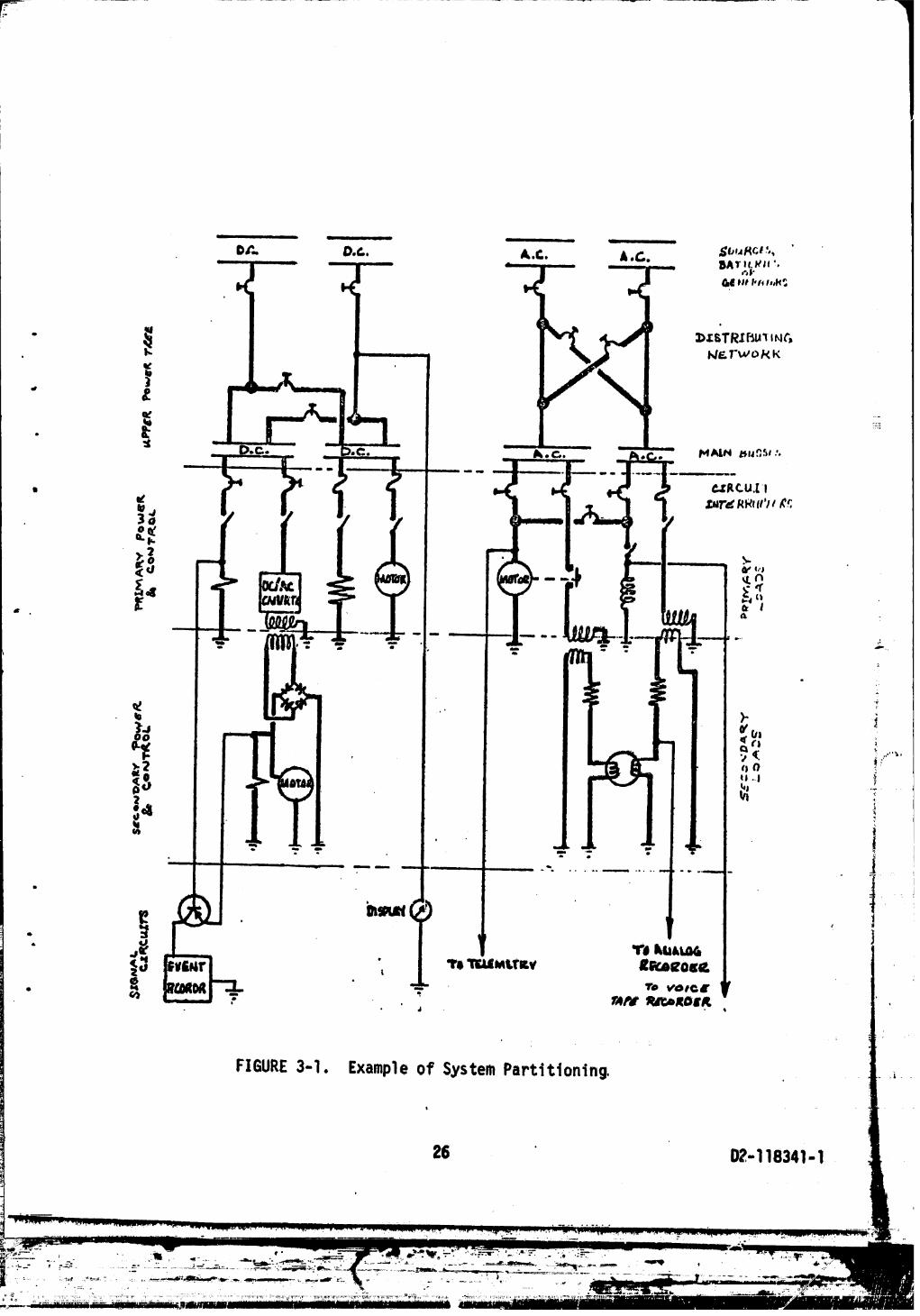
understandingof possibleelectricalcontinuitiesandswitchingconditions.In orderto facilitatethe analysis,the systemmay be dividedas follows: upperpowertree,primarypowerand control,secondarypowerand control,andsignalcircuits. Thesefourtiersof nperatingcircuitryare distinctlyidentifiable,and coverageof each is necessarybecauseeachmay containswitchingelements. Eachtieris111ustratedin Figure3-I.
I
3.2.I UpperPowerTree
• The upperpowertreeconsistsoZ the powersourcesand theprincipaldistributingelementsto themain busses. This .....networkdoesnot includeany loadsbut usuallycontainscircuitinterrupterssuchas contactors,circuitbreakers,fuses,and switches.
3.2.2 PrimaryPowerand ControlG
The primarypowerand controlcircuitsdistributepowerfromthe main bussesto primaryloads. Thus the originfor thiscircuitryis the circuitprotector(circuitbreaker,fuse)inmediatelyafterthe lowestbus in the upperpowertree. "Thesecontinuitiesextendfromthe circuitprotectorthrough .....interconnectwiringand controls,suchas switchesthatvary the circuitcontinuitiesin responseto operatingconditions,throughloadsfor returnto the powersourceor ground. The primarysideof transformersand.theinputto dc convertersare loadsincludedin thistier. ,_,'
3.2.3 SecondaryPowerand Control
This tierof circuitrywithina syste_containselementsthatare deliberatelyisolatedfromprimarypower. All
" secondarypowerfromtransformers,dc converteroutputsand associatedcircuitryare in thistier,with the exception
of the signalcircuitsas definedin the nextparagraph, i
" 3,2.4 SignalCircuits
This finaltierof systemcircuitryconsistsof continuities" and other energy paths that are used for control display,
recordingand status. The .signaltierof circuitryis con-slderednecessaryin the analysisbecauseit containsswitchingand may causesneakindicationsor have sneaklabels.
4
2S D2-118341-1
' j
1
• L
FIGURE3-1. Exampleof SystemPartitioning.
26 D_,-118341- 1
"_" 1971003012-TSD04

Logic circuits which are syr_chronized with timing pulsesare not included in sneak circuit analysis,
• 3.3 .Network ..Tr,ees
Afterthe schematic data has been verified and a system of• partitioningestablished,then the network trees car_be. constructedusing selectiveloss of detail. Construction
may begin o_the upper power tree and at each circuit breakercontrollingprimary power. It also may begin at secondarypower sources and switches controllingsignal circuits,
" The goal is to diagram all possiblecircuit continuities, •thereforeswitches are assumed closed in all positions.Standard symbologyis used where possible and supp]eLne_n_d_by simplified representationsas necessary.
The network tree presents the continuitiesand components• in a relativeposition to display the flow of power from
top to bottom. The simple example below shows characteris-tic dendriticbranchingat nodes to distributepower to ....several lower busses or loads.
| p_ ¢_ xwx _' Primary or '_iUpper ) _. i. SecondaryPower_ _ _ _,, Power& ]Tree t Control
• /
I [email protected],I_kI_IRY-
: L_BusA " i.eusS Lo_==_ .i4_
FIGURE 3-2, Elementary Trees
• ' 27 D2-118341-1 _;
.... " ............... 1971003012-TSD05
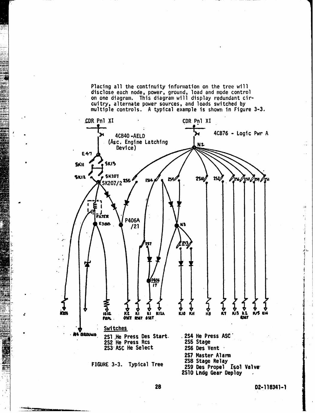
Placingall the contlnuityinformationon the treew111discloseeachnode,power,ground,loadand mode controlon one diagram. Thisdiagramwill displayredundantcir-cuitry,alternatepowersources,and loadsswitchedbymultiplecontrols. A typicalexampleIs shownIn Figure3-3.
o
.Cl_.Pnl X_I , CDRPnl XI
- I (As'c. Eng!ne Latchlng /_,_• / Devtce) ,_-__ _.._
_me
/ '' P406A "
• /21 .I i
t!
_' ,i._,,
J: •
• i !'-.- ' t
_. 2_/ )4aster Alam2S8 Stage Relay
FIGURE3-3. Typical Tree 2Sg Des Propel [sol Valve2S10 Ladg Gear Deploy
28 02-118341-1
1971003012-TSD06
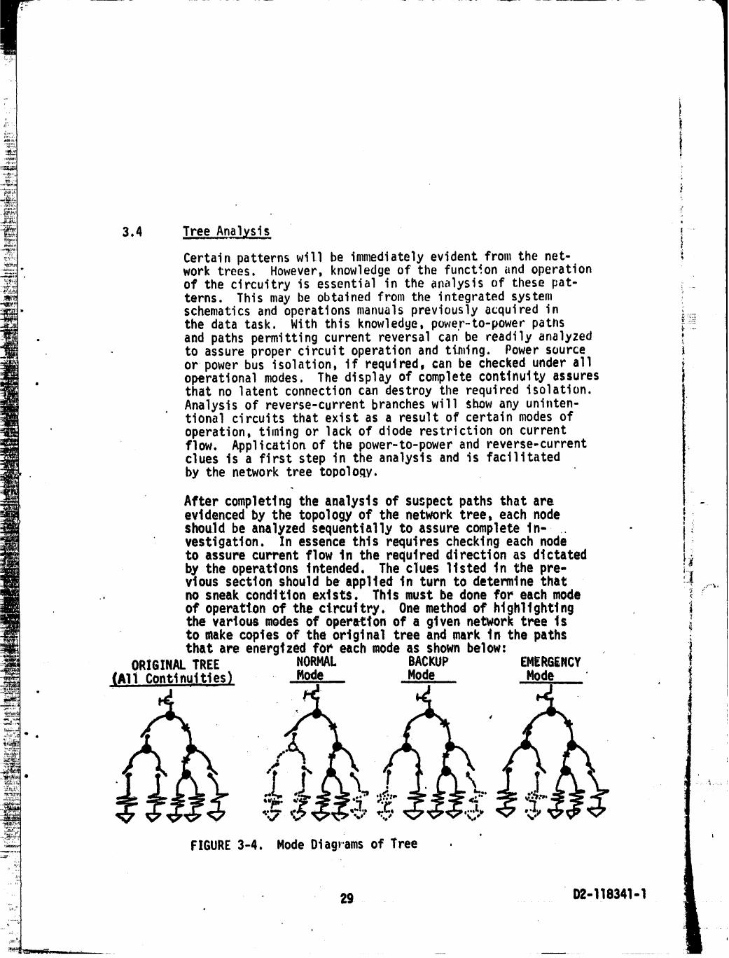
3.4 Tree Analysis i ....Certainpatternswill be immediatelyevidentfromthe net- iwork trees. However,knowledgeof the function_indoperationof the circuitryis essentialin tl_eanalysisof thesepat- i_terns. Thismay be obtainedfromthe integratedsystem ischematicsand operationsmanualspreviouslyacquiredinthe datatask. With thisknowledge,powe,r-to-powerpaths _:::
• and pathspermittingcurrentreversalcan be readilyanalyzedto assurepropercircuitoperationand ti_dng. Powersource ior_powerbus isolation,if required,can be checkedunderall I
• operationalmodes. The displayof completecontinuityassures uthatno latentconnectioncan destroythe requiredisolation.Analysisof reverse-currentbrancheswill _bowany uninten-tionalcircuitsthatexistas a resultof certainmodesofoperation,timingor lackof dioderestrictionon currentflow. Applicationof the power-to-powerand reverse-currentcluesis a firststep in the analysisand is facilitatedby the networktreetopoloqy.
After completing the analysts of su_.pectpaths that are -evidenced by the topology of the network tree, each nodeshould be aBalyzed sequentially to assure complete tn- ' _:vestigatlon.In essencethis requirescheckingeachnode :_
to assurecurrentflow in the requlreddirectionas dictatedby the operationsintended.The clues11stedin the pre-vtous section should be appited in turn to determine that ii_
.. no sneak condition exists. This must be done for each mode _ :""""
of operation of the circuitry, Onemethod of highlighting _,the various modesof operation of a given network tree ts _Lto make copies of the ortginal tree and mark tn the pathsthat are energ|zed for each modeas shownbelow:
ORIGINALTREE NORMAL BACKUP EMERGENCY(A11 Continuities) - Mode Mode Mode
.,.P. b:.
: o L
FIGURE3-4. ModeDiagrams of Tree ,
29......... _ I_-118341-I t' " '
1971003012-TSD07

A flnalstep in the analysisis the investigationof inter-relationshipsbetweennetworktrees. Thiscompositeanalysisrequlres_thoroughunderstandingof the functionalasoectsofthe totalsystem. Typicalinterrelationshipsare reiaycoil-to-contact,base-to-emittercontrolof transistorswitches,ate controlof logicelements,and motorswitchcontrols. ....n exampleof interrelatednetworktreesis shownbelow. .....Analysisof eachof thesetreesdependson operationsinanothertree.
¢
i.).£
FIGURE3-5. InterrelatedNetworkTrees !_
3.5 Snea,kCircu!.tAnalysisReporting _,
Two elementsof sneakcircuitanalysisremainafterthe sys-tem has beenanalyzedin detail. They°are the reportingof Tsneakcircuitsto the responsibleauthoritiesand the certi-ficationof analyzedcircuitryas beingfreeof sneakcircuits, jThe networktreesserveas a recordof analyzedcircuitry.A writtenreportaccompaniedby a schematicdiagramshowing ;;_the sneakpathor problemshouldbe used to makeaffectedpartiesawareof sneakcircuitsand of any requiredcorrectiveaction.
O
The sneakreportsshouldbe generatedand properlydispositionedas each sneakcircuitis discovered.It may also be desirable
• to concludeeachmajorproduct,mission,or systemwith asumnaryreportdescribingall the applicablefindingsof thesneakcircuitanalysiseffort. The overallanalysisand re-portingmay be assistedfor large,complexelectricalsystemsthroughdataprocessingas discussedin the nextsection.
30 D2-118341-1

3.6 computerAssistance_in Sneak_C.i.rcuitAnalysis
Two computerpr(_gramshavebeen developedto aid the Apollo" sneakcircuitanalysistask. Theseare the AutomatedFiling
Program(AFP)and the AutomatedSneakProgram(ASP). The ....AutomatedFilingProgramis an informationretrieval
• systemwhichwill store,sort,and reportdrawingindexinformation.The AutomatedSneakProgramis a complexsysteminvolvinga "pathfinder"programwhich tracescircuitcontinuitiesto derivevariousreportsused to
" assistengineeringanalysis, Thesetwo programsand theiruse will be discussedmore fullyin the followingparagraphs•
• 3.6.1 AutomatedFilingProgram(AFP)
The AutomatedFilingProgramis usedto establishthe sche- _maticbaselinefor the electricalanalysisby effectivity- _configurationlistings.Drawingand schematicindexing _detailsare inputto AFP. A masterfileis thencreatedfromthe drawingdata. Uponuser request,the masterfile .....
" informationis sorted,and the requiredoutputwill beprinted. AFP will thereafterproviderecallcapabilityfor ..otheruserrequests. Completedetailsare givenin D2-118243-I,"AutomatedFilingProgramRequirements".
3.6.1.1 AFP MasterfileInformation
The following,informationis containedin the AFP masterfile i".and is availablein variousformatsfor indexingthe refer- i_encedrawingsto be foundin the centraldrawingfiles:
a, Referencedesignatorof the componentor subassembly _F
b. Partnumberof the componentor subassembly _,
c. Schematicnumber :!• d. Schematictitle
. e. Vendorcode (namessupplier) i
. f, Proprietarycode (denotesclassification) |
. g. Released,but unincorporated,EngineeringOrders(EO's)
i
or AdvanceDrawingChangeNotices(ADCN's)
31 D2-118341-'_
1971003012-TSD09
h, Subsystemcodes
i. Filestatus(in fileor not) ....
" J. Vehicleor end producteffectivity
k. Revisionlettero
3.6.1.2 AFP Reports
The aboveinformationcan be sortedand reportedby the com-. puterin variousformats, The threemajor sortrout.4nesare:
a. Referencedesignator
• b. Partnumber
c. Schematicnumber
In eachcase,a reportcan be providedfor use in ascertain-ing fileand schematicinformation.For example,if only _;_the referencedesignatorof a sUbas.semblyis kDown,thefirstsortand reportroutinegivenabovewill showall
" pertinentpartnumbersand schematicnumbers. Likewise, .....if onlya partnumberis known,the partnumbersortandreportwill listapplicableschematicsand referencedesig- )nators. The schematicnumbersortand reportgivesall " _'_part numbersand referencedesignatorsassociatedwitheachschematic. Furthermore,thesereportsmay be orderedby 1indlvidualvehicleeffectivitiesor by a rangeof effectivi-ties,with the exceptionof the partnumberreport,Which ! .,.""'is availableby all effectivitiesonlywithinthe presentprogram. Of course,in each reportthe applicablerevision ]lettersand outstandingEngineeringOrdersare givenfor
each effectivity. -i
' 32 02-11834I- 1
" 1971003012-TSD10
3.6.2 AutomatedSneakProgram(ASP)
The AutomatedSneakProgramis designedto removeengineering• analysisdependencyupon integratedsystemschematics. Inte-
• gratedschematicsinherentlycontainerrorsbecausetheyare humanlyderivedfromthe manufacturinginformation.
• Hardwareproductionis basedupondetailschematicsandwire lists. Thesedocumentsare ,loreaccurate,complete,and timelythanthe integratedschematics,whichare generally
' producedwhen timeis availableand_forengineeringreferenceonly. Evensligl_terrorsor changeomissionsin the inte-gratedschematicscan completelyinvalidateer,jineering
• analysesbaseduponthoseschematics.The alternativeis useof detailschematicsand wire listsfor eachengIJ_eeringanalysis. Usually,the volumeof such informationis so .....greatthatit discouragesuse by an engineerconcernedwithoverallsystemknowledge.Moreover,suchdata is not in theformatdesiredby electricalsystemanalysts. The Automated Fl_a_,
SneakProgram provides a way of alleviating the menial task" of tracingcircuitcontlnu:itiesthroughdetailschematicsand
wire lists. A generaldescriptionof the programinputs,processes,and reportsand theiruses is givenin followingparagraphs.Completedetailsof the programoperationsaregivenir_D2-118081-2B,"Requirementsfor the AutomatedSneak :;Program,"and in D2-118211-1,"AutomatedSneakProgramSystemDocument." _,
3.6.2 1 ASP InDuts i ,,
The AutomatedSneak Programprocesses ctrcutt data from wtre !list tapes and from manually-prepared keypunchinputs which
represent continuities within equipment modulesand panels.The exact data and formats are discussed tn D2 118081 2B, _!as referenced above. However, any discussion of the formatswould be unique to Apollo and its multi-contractor environ- _
• ,tent; therefore, only the type of data processedwtll bediscussed here• AppendixA illustrates Apollo input coding
• techniques•
The wi re li sts mayalready extst on computer tapes, or they. may be generatedfromwhateverproductionwiringrecords
exist. The data must identify wire segmentstn terms ofFROMand TO end potnts which are usually plugs, Jacks, or
LI
33 02-118341- 1*
1971003012-TSD11
terminalboards. Of course,otherend terminationsareallowable.The basicideais thatthe wire listwill provide
t datanecessaryto describecircuitcontinuitybetweentheexternalconnectorson the equipmentmodules.
The equipmentmoduleinternaldata is suppliedby converting" the detailschematicsintopoint-to-pointcontinuitiesin
the formof a manually-prepared"internalwire list,"which _is thenkeypunchedfor computermasterfilegeneration.FROM _.:
" and TO end terminationsare usedto describecircuitcon-tinuitysegments,whichmay be modifiedwith functionalandlocationremarks,diodeand impedancenotations,plusa
' varietyof otherinformation,as give._in AppendixA ofthisdocument.
3.6.2.2 ASP Processes
The ASP systemprovidesfor updatingthewire listmaster-fileand the equipmentmodulecontinuitymasterfile,as
" requiredin orderto ensureaccurateand timelycircuitinformation.When the datamasterfilesare complete(or -at any otherdesiredtime),the programwill mergethe wirelistwith the equipmentmoduledatato providetotalcircuitcontinuityin one masterfile.The totaldata is thenassigned .....nunlericcodesduringa datareductionphaseof the programand thesenumericcodesare strungtogetherwherever continuity
• exists• In otherwords,the data is searchedfor completenu- .,.merlc "circuitpaths". Any incompletecircuits(open-endedwires) :iare alsofoundand reported.Aftera11 the datahas beensearched,the resultantnumericcircuitpathsare regeneratedback intothe informationcarriedon the wire listand equip-
' meritmodulemasterfilesfor easeof human interpretationand analysis.
3.6.2 3 ASPReports
The regeneratedcircuitpathsare reportedin the ASP Path !• Report(Seeexamplesof all reportsin D2-1.180BI-2B),The.,• Path Reportshowsthe circuitcontlnulty polnt-by-point wl_n
wire and equipmentmoduleidentifications,pertinentdrawing ._numbers,diode,impedance,and remarksinformationas
• originallyinputforeachdatasegment. The namingconvention 'of the pointswill Identif_switches,circuitbreakers,re-lays,motors,and othersuchcircuitcomponentsand loads.The PathReportthereforerepresentscircuitsin a listingform ratherthanpictorially,and also provtOes
34 D2-118341-1

referenceinformationwith functionalremarks. Moreover,thePathReportformsthe baselinefor manyderivedreportstoassistengineeringanalysis•4
The reportsderivedfromthe pathsare: NodalSet Matrix,TerminalBranchReport,SwitchBranchReport,LoadReport,
" DiodeReport,and SpecialNodeCross-ReferenceReport,Thesereportsare discussedbelow,generallyas a packagecompos-ing a "NodalSet,"which completelydescribesa networktree.
•a. NodalSet Matrixm .... _ iJ .
• This reportconsistsof a "connectivityarray"whichidentifiesthe nodesin a networktree (relatedpaths)and showstheirrelationshipto one anotherwi1:hineachpathwhichformsthe tree. Diode,switch,and loadinformationis alsocontained•The reportis usedtosketchthe networktreeand provides"selective-suppression....of-detail"to simplifytopologicalanalysis.
b. TerminalBranchReport '.
This reportliststhe firstand lastbranches(segments) . _,of _achpathof the NodalSet matrices. The information ,!is used to labelthe powersourcesand groundpointson -yeach networktree. Openend points,whichshowuntermi-hatedwiresor datadiscontinuities,are alsogiven _
c, .SwitchBranch.....Report 4
This reportlistsa11 the circuitbreakers,switches,and i_umbilicaldisconnectsin eachnodalset and references •theirrespectivepaths. Eachitemcarriesits remarks _and otherinformationcodedintothe originalinputdata.The reportis usedto comparefunctionsof the switches
. withina tr_eand to labelswitchsettingsand functionson the treesketch. It alsocallsattentionto the fact
• thatumbilic+Jldisconnectsmustbe treatedas switchesin sneakcircuitanalysisbecausetheyare uncoupled
• duringthe anticipatedsystemoperation.
• d. LoadReport
Thls ASP reportlistsall the itemswithina nodalset
e j
35 02-118341-1 _i
....'"................ '_- ' ........ 197i O03012-TSF01

thatare codedin the originalinputdataas circuitloads("L"- itemnames). It is used to draw and labelpertinentloadson the networktreesketch. A remark
' will identifythe functionof each load.
e. DiodeReport
This reportliststhe diodesand theirrespectivepaths• withineachnodalset. It is used to drawand labelall .
diodeson the networktree. The inputremarkswillprovideany specialinformationregardingeachdiode.
" f. Specia.l.Node C.ross-Ref.e.renceReport
ThisASP reportprovidesa £unctionalcross-referencefor specially-codeditem._withineach nodalset. Forexample,Kl may representa relaycoilin NodalSet 003.The SpecialtlodeCross-ReferenceReportfor NodalSet
, 003 will thenshov_the.nodalset identificationofcontactscontrolledby KI. Multiplerelationshipsareallowed,and the cross-referenceis givenfor each ....specialnode-- i.e.,both for the coiland for thecontactsin theirrespectivenodalsets. Of course,the cross-referencetechniqueis appliedto many__usesin additionto relaycoilsand contacts.
3.6.2,4 ASP Tree-SketchingProcedure ;
The ASP reportsare usedper thefollowingproceduresto _completelysketchand labelthe networktrees:
a. Sketchthe Treem i • m
Use the Matrix,TerminalBranchReport,SwitchReport, iLoadReport,and DiodeReport, It is suggestedthata
" roughdraftof the treebe made fromthe matrix,thenredrawnfor betterlayoutbeforelabelingthe tree. )Sub-treecrossconnectionsthroughhigh impedancemay ,_•
• be shownas openswithnotationof impedanceand re-ferencesbetweensub-treeswhenmore thanone page isrequired.
6
36 I)Z-118341- 1 ....
1971003012-TSF02

, FIGURE 3-6. High Impedance Sub-Tree Partitions
b. Add Labels to Tree
Identi fy nodes, power sources, grounds, swi tches, loads,and diodes. Use the Terminal Branch Report, SwitchReport, Load Report, and Diode Report as required. Any
- "special"nodes or points (I, SI; K, SK item types)found in the Baths should be shown on the tree andcross-referencedto their associatedspecial nodes byusing the Special Node Cross-ReferenceReport.
,, !
I) Umbilicalsand Stage Breaksmust be shown as an Xo_nthe tree. Use the Switch Report, ....
k_ ._.
C
; ' os,i/i,(TM]
l_/: " FIGURE 3-7. Umbllicalson Tree "'m
3
2) Loads and Diodes will be identifiedfrom the Load '._" Report anclthe_DiodeReport, Label the items on
the tree. The sketch should reflect the type of "_load per Figure 3-8. -i_
. 37 D2-118341-1
1971003012-TSF03
3) Switchesshould have both pins shown to indicate• • iJ -o_
pos]tlons. Functionallabelsmust be shown.
" 4) Notes should be written to explain the circuitTu'nc'tionand provide other informationto aidanalysis.
5) Titles should be used on each sketch to identify• the network.
c. Verify the Tree against integratedand detail schematics• where necessary•
I) Make any necessarydata correctionson the tree andin tilecomputer-datamasterfi_e.
2) Yellow-linethe areas of the integratedschematicm_py that are repre's-en-tedby the tree'.'Yhis
• Will_provide a check on circuit coverage and dis-cover drawing errors or data discrepancies.
,i
d. Show the OperationalModes of the tree configurationbycopying the orig'ina'ltre'eand drawing the switches intheir proper position for each functionon a separate '=copy. Title each copy to define the operationalfunction.DO NOT ATTEMPT TO SHOW ALL SWITCH PERMUTATIONSOF THE TREE.
An extra copy of the original tree should be made for .._'future use _nd filing•
After the tree is completelyd'rawnand labelled,analysisfor sneak circuits proceeds as discussedearlier inSection 3.4 of this document.
3.6.2.5 AdditionalASP Capabilities
The Automated Sneak Program in its present state assistssneak circuit analysis. It also serves as a data source
• and baseline for various special tasks• In addition, it
can provide a foundationfor many developmentsin the field _of computer applicationsto engineeringendeavors. Some• of these areas are discussedin the followingparagraphs.
The data mesterfilesof the Autoz,_atedSneak Program areuseful data for sorts to determineand iist such things
o
t
38 I)2-118341-i
1971003012-TSF04

HEMER RESISTOR CAPACITOR INDUCTOR; TRANSFORMER"CIIOKE"
RELAY REL'AY.............TRANSISTOR TRANSISTOR DC-TO-DC• CONTACTS COIL AMPLIFIER SWITCH.............CONVERTER
I .
MSW
i.
11_ANSDUCER LAMP MOTOR MOTOR IRON-CORESOLENOID; .....t
" ........_.............. SWITCH "BARBERPOLE";VALVE _t
o
MULTIVIBRATOR POWER DIGITAL-ANALOG GATE GATE '-SUPPLY CONVERTER POWER INPUT
FIGURE3-8. Load Symbolsfor Tree Sketches
39 D2-118341-I -
as all circuitbreakerswith theirratings,functions,loca-tions, and applicable schematics. Sucha sort can easilybe producedfor switches,umbilicals,loadsof varioustypes,
- diodes,monitorpoints,etc. The listingcan also includea referenceto the pertinentnetworktreeby nodalsetnumber.
, Engineeringanalysesotherthansneakcircuitscan use the .,networktreesketchesproducedthroughASP. Batteryand
• bus loadingstudies,FailureMode EffectsAnalysis,wiresizingstudies,anomalyand changeanalysis,and otherengineeringtaskscan use the treesto gainquicksystemknowledge,thensupplementthe treeswith the pathsand
" otherreports_or accessto specificdetailsand location ,'_of applicableschematics.Indexesare producedto enable ,....speedylocationof any circuititemin its ASP tree,and _fromthere,relatedinformationmay be obtainedthroughASPdata.
. An area thatshou.ldbe pursuedwithinASP is thatof provld-Ing "changepackage"capabllity_erein onlydifferencesarereportedwithintreesproducedbysuccessiveASP runs•(Infact,sucha programrequirementspecificationhas beenpre- _paredin Houston:inter-departmentcoordinationsheet5-2933-HOU-065-OI4,"NodalSet ComparisonProgram") Evenbetter _wouldbe a capabilityto run the programto processonly .....changeddataand reportaccordingly,(A "crutch"methOdofperformingthatfunctionis now availablethroughselective _,circuitsearches,but thispresupposesthatthe changedareas
kn ) _-- are own. _,
Withinpresentstate-of-the-artis the capabilityte use data _producedby ASP to generatenetworktreesdrawnon microfilm/ iCRT plottersby a computer. Suchtreescan eliminatethe (manualsketchingtasknow requiredto utilizeASP output. _The computer-producedtreescan be expandedto variouslevels
• of detailand replaceor supplementexistingintegratedschematics.The sametechniquecouldleadto automateddetail
" schematics,with engineeringinformationreleasedentirely i.i- throughdataprocessing.
• Perhapsthe ultimatemachineutilizationin engineeringtaskswill comewith interactivegraphicswherebyan on-lineCRTterminalis usedto displaythe treesat a contlnuously
I
12:.
' 40 D2-118341-1
1971003012-TSF06

--" I
variable selectlvelevel of detail to supply the greatestassistancein network analysls. Such a terminalcould a1_(,be used for real-timechange input, aiialysis,approval,andrelease. It would provide instantaneousdata availabilityand correctioncapability,and feedback channelscould beincluded from all users in the productionenvironment. A
, system of such terminalscould then evolve into a replace-ment for existing techniquesof engineeringconB_unication
• on paper through drawings. The CRT display terminal systemwould offer inherentadvantagesin data availability,quickerreaction time for changes, and space/weightsavings over the
• existing drawing systems of communication. :
• i
i
41 O2-118341-I
1971003012-TSF07
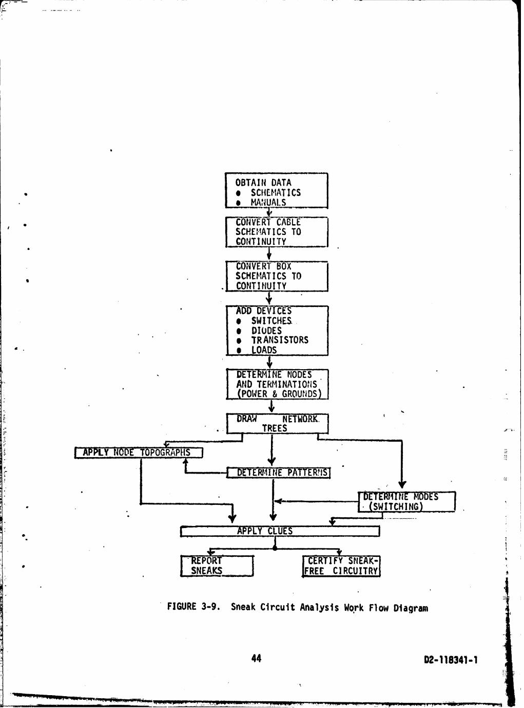
j.7 Summaryand Conclu,stons
Figure 3-9 shows the steps involved in performing a sno.k,circuit analysis. The flow diagram i_ generalized,a_d tr,_conversionof data to continuities,etc., is necessary__r t,,.purelymanual or the computer-assisteTapproach. The diffuru,._._arise in formats, techniques,and orderlinessof record keepi_9.The automatedmethod offers other advantagesover the manualapproach. These are:
• a. Removes dependencyupon "derived"system schematics,whichmay not be._t'asbuilt"
• b. Providesdifferent p(rspec_ive,forcing analyst to seecircuitrydifferent from designer'sviewpoint
c. Traces detail continuityfaster than manual, without tiringor overlappingareas
d. Forms general data base for other engineeringuses I_# !,
e. Offers developmentcapabilitiesfor new applicationsand _Iproce _es
!
Disadvantagesof automationare:
a. Data p_rocessingequipmentrequirements
b. Learning curve for techniquesand operatingknowledge _.......,.of program operations -_
c. Batch processesat present,rather than quick, selectiveresponse offered by on-line systems '_
Sneak circuit analysis has been found to be expensive,but _worthwhile, One sneak occurrencecan cost more than the _. iI
• entire analysis. Ideally,the analysis should be performedas _ !soon as complete design details are known,and it shouldbe _
" conducted by ateam independentfrom the design organization _i
. to avoid prejudice in systemreliability. In any event, theanalysis must be performedby personnelwith total system i
" overview capability,for it is the subsystemor assembly 'interconnectionswhich most frequentlygive rise to sneakprobabilities. Each componentand assembly is usually adequatelydesigned and tested to do its Job in a fixed environment,butas the total system size and complexity gro_s, so does thecapability of the anticipated environment to change unexpectedly.
42 D2-118341-1
_.._ . .- --- : _ _ _. .
, .... ,.................. ,, vu • ,
1971003012-TSF08
Sneakcircuitanalysisoffersan approachto more completelydetennineall possiblesystemmodes,both the expectedandthe unexpected.Therefore,sneakcircuitanalysiscan help
• reducesystemcostsby preventingunexpectedequipmentdamageduringtestplussubsequentredesign.andretest.Moreover,sneakcircuitanalysiscan _,elpachievea more ....
" "failsafe"productthroughcompleteevaluationof all system, responseswhichmay be broughtaboutby proceduraldiscre-
pancies. Finally,throughthe variouslevelsof overview. providedby the selective-loss-of-detailapproachin sneak '
circuitanalysiscoupledwith automateddisplaydevices,new dimensionsin engineeringcapabilitymay ariseto suc-
, cessfullydesignand integrateever largercomplexsystems.
43 D2-118341- 1
1971003012-TSF09
IoBTAIiDATA......• | e SCHEHATICS
| e _tlUALS;21....2_2_ii--2--
• I CONVERTCABLE - I' I SCHEHATICSTO J
J CONTINUITY !
C0NVE_Ry_B-_O-X....., SCMEHATICSTO
• CONTINUITY
• -A-ODDEVFCES''e SWITCHES..• DIODESe TRANSISTORS
" e _LOADS
• j_ 1)ETE_41fieNODE! AND TERHINATIO,_ISJ (POWER& GrOUtiDS) ....
- NE_ '.- • TREES .,...,.
:-..:
- . ; SWITCHING '
!
• * SNEAKS E CIRCUITRY _.
FIGURE3-9. SneakCircuitAnalyslsWRrk FlowDiagram
44 I)2-116341-I
1971003012-TSF10
.F_==-._--
D2-118341-1
APPENDIXA
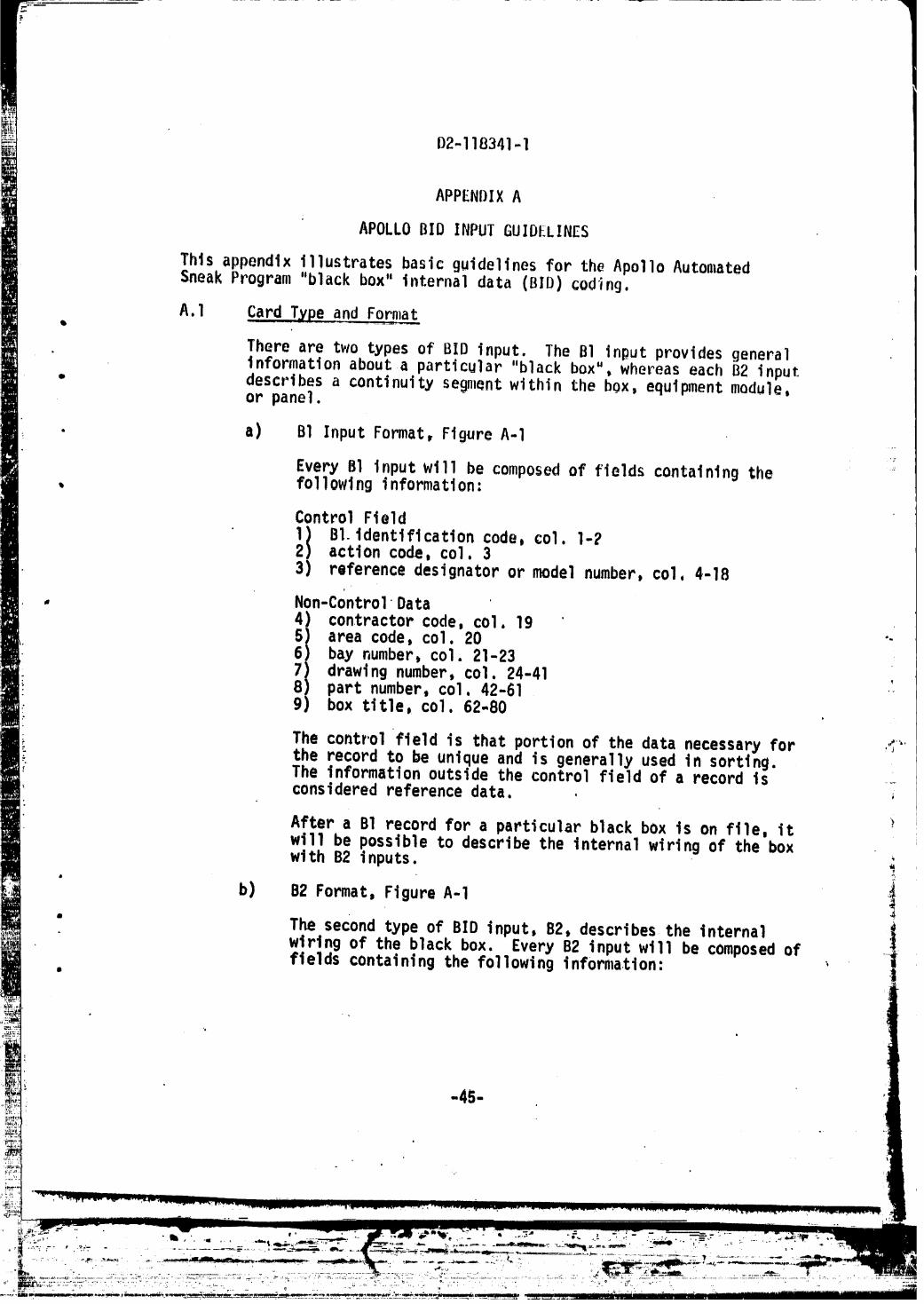
APOLLOBID INPUTGUIDELINES
Thisappendixillustratesbasicguidelinesfor the ApolloAutomatedSneakProgram"blackbox"internaldata (BID)coding.
A.I CardType and Fornlat
Thereare two typesof BID input. The BI inputprovidesgeneralinformationabouta particular"blackbox",whereaseachB2 input
- describesa continuitysegmentwithinthe box,equipmentmodule,or panel.
• a) B1 InputFormat,FigureA-I
EveryB1 inputwill be composedof fleldscontainingthe *=, followinginformation:
ControlField1) BI.identificationcode,coi. I-?2) actioncode,coi.33) referencedesignatoror modelnumber,coi,4-18
, Non-ControlData
!i contractorcode,coi,19areacode,coi.20 ""
' bay number, coi. 21-237) drawingnumber,c01. 24-418) partnumber,coi,42-61g) box title,coI. 62-80
The controlfieldis thatportionof the datanecessaryfor ,'C"'the recordto be uniqueand is generallyused In sorting•The informationoutsidethe controlfieldof a recordIs ....consideredreferencedata• .
After a BI recordfor a particularblackbox is on file,itwill be possibleto describethe internalwiringof the boxwlth B2 inputs.
!b) B2 Format,FigureA-I
• The secondtypeof BID input,B2, describesthe internal ,_wiringof the blackbox. EveryB2 inputwill be composedoffieldscontainingthe followingInfornlatlon: '
1971003012-TSF11

D2-11B541_l
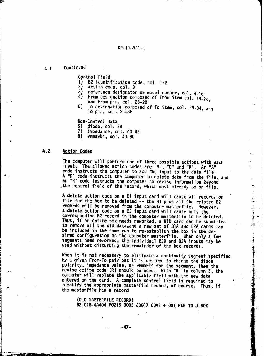
:,. I ContJnued ,
.Control Field
I B2 identificationcode,col.I-2
actioncode,col.3referencedesignatoror modelnumber,col.4-I}:Fromdesignationcomposedof Fromitemcol,19-2,:.and Frompin,col.25-2B ,
5) To designationcomposedof To item,col.2g-34,and .....To pin,col.35-38
Non-ControlData• 6) diode,coI. 39
7) impedance,col.40-428) remarks,co'l,43-80
# ,b
A.2 ActionCodes .......i
The computerwill performone of threepossibleactionswith eachinput. The allowedactioncodesare "A","D"and "R", An "A" 'code instructsthe computerto add the inputto the datafile.
- A "D"code instructsthe computerto deletedatafrom the file,and ....an "R" codeinstructsthe computerto reviseinformationbeyond.thecontrolfieldof the record,whichmust alreadybe on file. "
A deleteactioncodeon a B1 inputcardwill causeall recordson _filefor the box to be deleted-- the BI plusall the rela_edB2 +recordswill be removedfromthe computermasterfile. However,a deleteactioncodeon a B2 inputcardwill causeonly the ._correspondingB2 recordin the computermasterfileto be deleted, __'Thus,if an entirebox needsreworked,a BID cardcan be submitted ....__._.
to removeall the old data,anda new set of BIA and B2A cardsmay :_be includedin the samerun to re-establishthe box in the de- ._siredconfigurationon the computermasterfile. Whenonlya fewsegmentsneedreworked,the individualB2D and B2A inputsmay be
usedwithoutdisturbingthe remainderof the box records. '_
I, When it is not necessaryto elimlnatea continuitysegmentspecifiedby a givenFrom-Topairbut it is desiredto changethe diodepolarity,impedancevalue,or remarksfor the segment,then the
... reviseactioncode (R) shouldbeused. With "R" in column3, thecomputerwill replacethe applicablefieldwith the new data
• enteredon the card. A completecontrol field is requiredtoidentifythe appropriatemasterfilerecord,of course. Thus, if
* the masterfile, has a record
(OLD_%STERFILERECORD)B2 C15-4A404P0215 0003 J0017 OOA1+ 001,PWRTOJ-BOX
•, -47-
1971003012-TSG01
D?.-118341--1
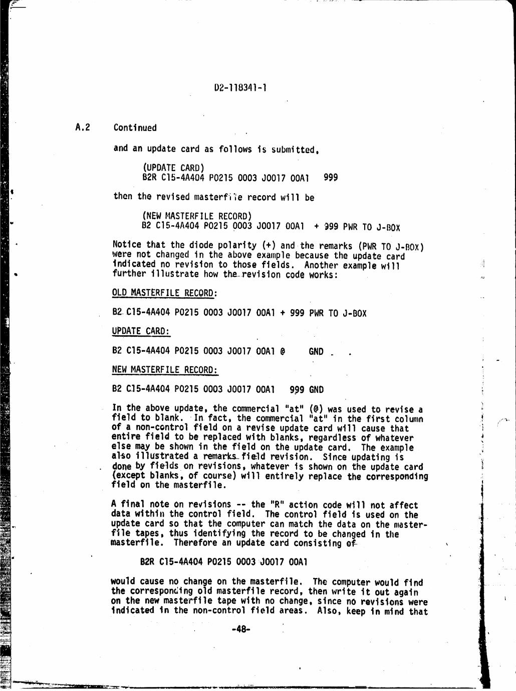
A.2 Continued
and an updatecardas followsis submitted,
(UPDATECARD)B2R C15-4A404P02150003JO017OOAI 999
thenthe revisedmasterfi'lerecordwill be
(NEWMASTERFILERECORD)" B2 C15-4A404P02150003JO017OOAI + '@9gPWR TO J-BOX
Noticethatthe diodepolarity(+) and the remarks(PWRTO J-BOX)were not changedin the aboveexamplebecausethe updatecardindicatedno revisionto thosefields. Anotherexamplewill ,i
, furtherillustratehow the..revisioncodeworks: ....
OLD HASTERFILERECORD:i i . _ j _ .,.
B2_C15-4A404P02150003JO017OOAI+ ggg PWR TO J-BOX
UPDATECARD:u
B2 C15-4A404P02150003J0017OOAl@ GND .
NEW MASTERFILE RECORD: 'ii
B2 C]5-4A404P02150003J0017OOAI g.ggGND i
In the aboveupdate,the commercial"at" (@)was used to reviseafieldto blank..In fact,the commerclal"at"in the firstcolumn _! .....,.of a non-cQntrolfieldon a reviseupdatecardwill causethat ientirefieldto be replacedwith blanks,regardlessof whatever ._elsemay be shownin the fieldon the updatecard. The examplea1_oi11ustrateda rema_ks_fieldrevision. Sinceupdatingis '_doneby fieldson revisions,whateveris shownon the updatecard_exceptblanks,of course)willentirelyreplacethe corresponding ._
fieldon the masterfile, j
A finalnoteon revisions-- the "R"actioncodewill not affectdatawithin the controlfield. The controlfieldis usedon theupdatecardso thatthe computercanmatch the dataon the master-file tapes,thus identifyingthe recordto be changedin tllemasterfile. Thereforean updatecardconsistingof_
B2R C15-4A404P02150003J0017 OOAI
wouldcauseno changeon the masterfile.The computerwouldfindthe correspondingold masterfilerecord,thenwriteit out againon the new masterfiletapewithno change,since no revisionswereindicatedin the non-controlfieldareas. Also,keepin mind that
-48-
e
'!
1971003012-TSG02
:r
D2,-118341- 1
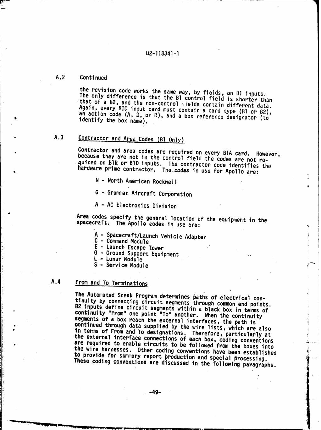
A.2 Continued
the revision code works the sameway, by fields, on B1 inputs.The only difference is that the B1 control field is shorter thanthat of a B2, and the non-control _ields contain different data.Again, every BID input card must contain a card type (B] or B2),an action code (A, D, or R), and a box reference designator (to
L identify the box name).
. A.3 _Contractorand Area Codes(BI Only)
Contractorand areacodesare requiredon everyBIA card. However,' becausethevare not in the controlfieldthe codesare not re-
4ulredon BIR or BID inputs, The contractorcode identifiesthehardwareprimecontractor.The codesin use for Apolloare"
N - NorthAmericanRockwell ,_
G - GrummanAircraftCorporation
A - AC E1ectronlcsDivision
" Area codesspecifythe generallocationof the equipmentin thespacecraft.The Apoliocodesin use are: .h
_'- i
A Spacecraft/LaunchVehicleAdapter: " CommandModuleE - LaunchEscape Tower
GroundSupportEquipment "il " LunarModule f_.S - ServiceModule
A.4 From,and To,.Terminationsi
The AutomatedSneakProgramdeterminesl_atfisof electrlcalcon-tlnuityby connectingcircuitsegmentsthroughcommonend points.B2 inputsdefinecircuitsegmentswithina blackbox in termsof
. continuity"From"one point"To"another. When the continuitysegmentsof a box reachthe externalinterfaces,the path is
. oontinuedthroughdatasuppliedby the wire lists,whichare also, in termsof Fromand To designations.Therefore,particularlyat
the externalinterfaceconnectionsof eachbox_codingconventions •_are requiredto enablecircuitsto be followedfrom the boxesinto
• the wire harnesses.Othercodingconventionshave beenestabllshed ito provideforsummaryreportproductionand specialprocessing.
• Thesecodingconventionsare discussedin the followlngparagraphs.
1971003012-TSG0:
!
D2-118341 ,-1{
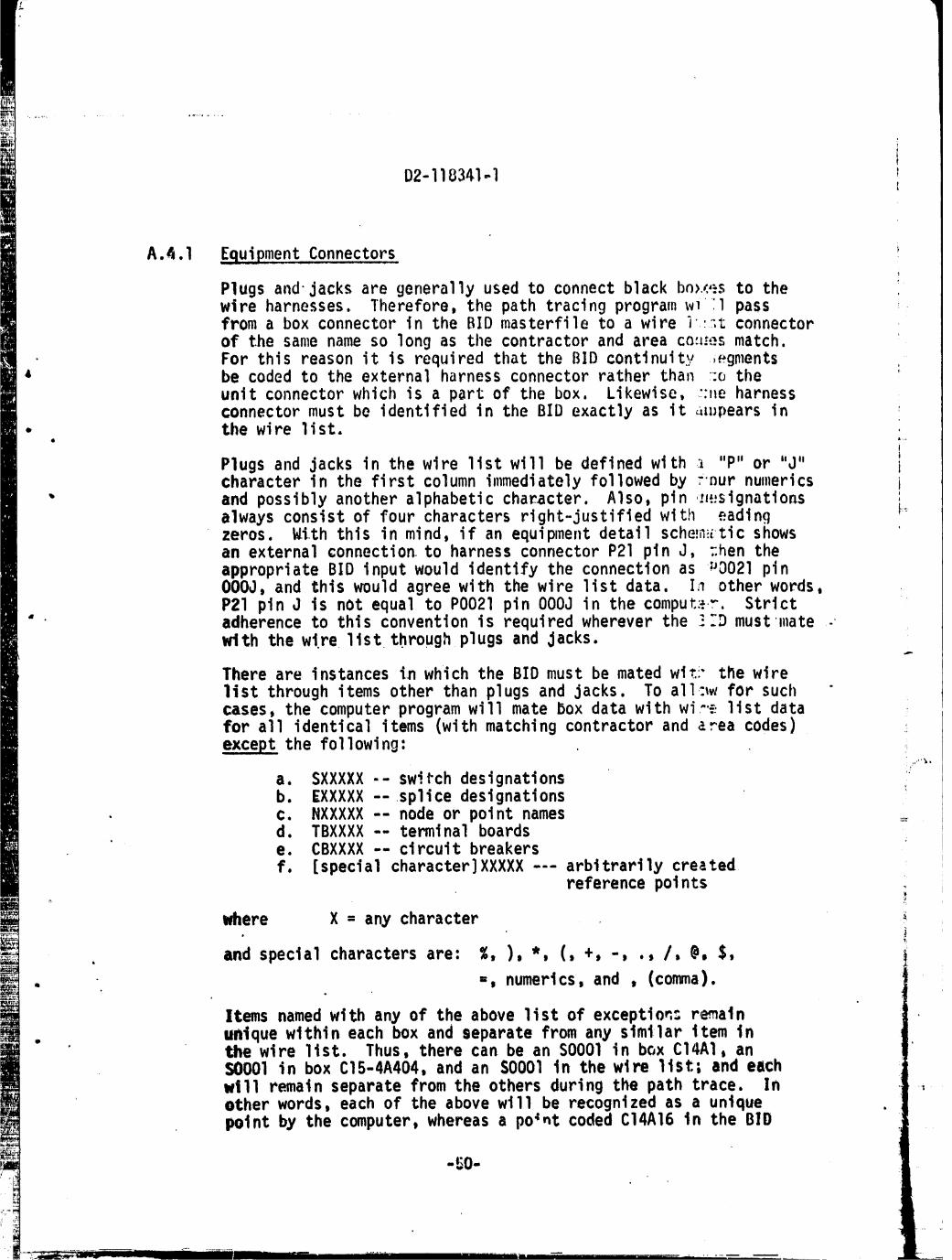
A._.I Equipment Connectors
Plugs and jacks are generallyused to connect black bn>._;,_sto thewire harnesses. Therefore,the path tracing program _vi'l passfrom a box connectorin the BID masterfileto a wire i :_t connectorof the same name so long as the contractorand area co._:esmatch.For this reason it is required that the BID continuity .egments
4 be coded to the external harness connectorrather than ::otheunit connectorwhich is a part of the box. Likewise, "'_eharnessconnectormust be identifiedin the BID exactly as it auJpearsin
• the wire list.ii
Plugs and jacks in the wire list will be defined with _ "P" or "d" icharacter in the first column immediatelyfollowed by _nur numerics i
i
" and possiblyanother alphabeticcharacter. Also, pin .;_,.;signations i.._always consist of four charactersright-justifiedwith eadingzeros. With this in mind, if an equipmentdetail sche!n_i:ticshowsan external connectionto harness connector P21 pin J, :.hentheappropriateBID input would identify the connectionas uC)021pinO00J, and this would agree with the wire list data, In other words,P21 pin J is not equal to PO021 pin O00J in the comput'=..r.Strict
• adherence to this conventionis requiredwherever the !.'Dmust mate -with the wire list through plugs and Jacks.
There are instances in which the BID must be mated wi_i-tl_ewirelist through items other than plugs and jacks. To all:_wfor suchcases, the computer program will mate box data with wi-..=,list datafor all identicalitems (withmatching contractorand area codes)except the following:
i:v
a. SXXXXX -- switch designationsb. EXXXXX --splice designations
• c. NXXXXX -- node or point names =d. TBXXXX -- terminal boardse. CBXXXX -- circuit breakersf. [specialcharacter]XXXXX--- arbitrarilycreated
reference polnts _i
where X = any character•
• and special charactersare: %, ), *, (, +, -,., /, @, $, i
, =, numerics,and , (comma)
Items named with any of the above list of exception: remain• unique within each box and separate from any slmilar item in
the wire list. Thus, there can be an SO001 in box C14AI, anS0001 in box C15-4A404,and an S0001 in the wire list; and eachwill remain separate from the others during the path trace. Inother words, each of the above will be recognizedas a uniquepoint by the computer,whereas a point coded C14A16 in the BID
-50-
1971003012-TSG04

D2-118341-1
A.4.1 Continued
will be taken to be Identical to a point namedC14A16in thewtre 11st. Of course, pin data is also matchedfor every itembefore uniquenessor equivalence is determined.
J A.4.2 Sp]ices, and,.Ngd,es
Internalsplicesand arbitrarily-namednodes will be coded with' • "E" onlyif the detallschematichas identifiedpoints-onthe __
drawingwith suchnames. The "N" code is commonlyusedwhen .....• assigninga nameto an otherwiseunlabelledjunctionof linesin
the drawing. The use of a_.bitrary"E_'and "N" codesshouldbeminimizedfor.easeof subsequentreferencefromcomputerpaths to
, integratedschematics,whereinthe "E"and "N" itemswill not befound. Frequentlyan unIBbelledjunctionof lineson a drawingcan be namedas one of the itemsto which It connects-- i.e.,the
'. lengthof a linewithoutimpedance,etc.,can be shortenedto zero. _.
A.4.3 TerminalBoards-andCircuitBreakersiu .....
Internalterminal.boardconnectionsshouldbe codedin the BIDexactlyas shownon the detail_schematics.It will,however,benecessaryto createFrom-T_-continuitiesfor the bussedpinconnections..Otherwise,each internalterminalboard_pin wiIlremainisolatedfrom all otherpinsof the terminalboard.
Circuitbreakers_ithina panelshouldbe namedas givenon the ..,_.detailschematic,so longas the "CB"codesare enteredin thefirsttwo columnsof the itemfield. It will be necessaryto
i_ entereachpin of the breaker,alongwith theirconnecteditems, ' ,L and_thento createa segmentbetweenthe pins. Thus,to completely
' specifycontinuitythrougha circuitbreaker,theFrom-To sediments i_t would be: i_
From To
" Point.X CB5-O001CB5-0002 CBS-O001CB5-0002 PointY
A'4.4 Switches and Fuses= i __ • , ,, JH
- The computerwill treatas a switchany seg,_entwith IdenticalFromand To items(anddifferentpins)th{_tbeginwith the letter"S". Thus,many typesof switchescan be specifiedby using"S"plusotherconventlor_sfor the remainderof the itemname. For
-51-
_j
__L:_:.... , .... , "....'...._- "' ........ _ 1971003012-TSG05

o
D2-118341--1
A.4.4 Continued
example, S-numeric is generally accepted as a manual switch intheApollodatabase,whereasSQ-numericdenotesa transistorswitch. Likewise,"SK" (followedby numerics)is used for relay
"SCR"for sillcon-controlledrectifierscontacts,"SLV"for valves,"SM"for motor switches,and so forth.
8
As was the casefor circuitbreakers,continuitysegmentsmust be' suppliedbetweenthe pinsof a switch. Thus,for a simplesingle-
- pole,single-throwswitchthe continuitywouldbe:
. From To
Poinf_ A $1-0001S1-0002 SI-0001
" SI-0002 PointB
For slightlymore complexswltch,such-asthe shortingswitchillustratedin FigureA-Z, the continuitywouldbe:
From ToG
Point C $2-0001$2-0002 $2-0001 "
- $2-0002 PointDS2-O001 S2-0003PointE $2-0003$2-0001 S2-0004Point F $2-0004$2-0002 $2-0003 ._""$2-0003 $2-0004 i
.'-- where the 'lasttwo segmentsdenotethe shortingfeatureof the
switch, _
• _'2 ....O. ..... ........(_ 1_ ........E. ........__
% v l.-.3
F.o • .I- . ..
O 4e
S2 '
i
Figure A-2. I11ustratlonof Shorting Switch
"" "' _---_--";'-.................. _............. 1971003012-TSGOE

02-118341-1
A.4.4 Continued
Multiple-pole,multi-throwgangedswitches,as 111ustratedinFigureA-3, can be codedto denoteeach throw:
From To
• Point G $3-0001$3-02T1 $3-0001$3-02T1 Point I
• S3-0001 $3-03T2' Point J S3-O3T_)
PointH S3-0004' S3-OSTI S3-0004
S3-05T.1 Point KS3-0004 $3-06T2
• PointL $3-06T2
I
G 1__0, _2.... "
.%-!!
H 4._ 5 _.L
S3
FigureA-3. Double-Pole,Double-ThrowGangedSwitch
In the abovecodingthe "throws"are arbitrarilynumberedas......... I and 2. The letter"T" in the pin fielddenotesthe throw
number(position),and the firsttwo digitsof the pin fieldareusedto specifythe actualpin number. Suchcodingwilla11ow
• recognitionof the natureof the switchin th_computerreportsand will facilitatesubsequentanalysisof the networktreeswith respectto switchingmodes.
0
Fuses wi_l also be codedas switches because they may "open" a_ circuit,and the treemust be analyzedfor sucha situation.
• Therefore,the code "SF"'isreservedfor fuses,and the contl-nuitymust be specifiedIn termsof pln numberswhichcreatea
. "switchbranch":
-53-
--T
- 1971003012-TSG07

D2-118341-1
A.4.4 Continued
Fronl To, m . --.
Point M SF15-O001SF15-0002 SF15-0001SF15-0002 Point N
The pin numbersmust be supplted and may be arbitrarily assigned ifo none are given on the detail schematic.
. A.4.5 Loads and RelayCoils
Circuitloadsotherthanbiasingresistorsand the likeare to' be codedwith the character"L" for the Fromitem'of_the-segment
containingthe load. Eor example,the codes
• From To
PointP L1LI PointQ
might be used for the exampleof FigureA-4.....
a
- p
.........". ' IFIL.FLF...........LI
t
FigureA-4. LoadCodingExample Y_"
Variouscategoriesof loadscan be specifiedthroughthe establish-ment of additionalcodingconventionsas was done for switches. _i
"LH"denotesa heater_"LTF"denotesThus, "LM" denotesa motor,transformersD and so forth, The remainderof the itemand pinfieldscan be used to specifyuniquenesswithineachbox.
• t'
"K" for aRelaycoils are loadswhichreceivea specialcode, , ispecialpurpose. The use of thiscodeallowsthe computerto
; reportthe relationshipbetweena coiland its contacts,eventhoughtheymay be in differentpathsand trees. This is ac-complishedthroughmatchingK-itemswith SK-itemsin the samebox. !
• A matchwilloccurif the K-itemis identicalto the SK-Itemwith-out the "S". Pinsare not compared,nor is the last characterof •the K-Itemfield,whichmay thusbe used to specifyuniquenessofseveralcoi1_relatedto the sameset of contacts. The K-itemmust be identifiedrelativeto the segmentcontainingthe coiljust as was done for other loads.
-54- , . .
1971003012-TSG08

D2-I18341-I
A.4•6 S__pec_ia1_No_de__
•In additionto the specialpurposec.'Ingof "K" and "SK"itemsdiscussedabove,anotherset of codeshavebeen reservedfor asimilarpurposewhereverdesired li}esecodesare "I" and "SI"• l
and theymay be used to definea relationshipbetweenany twoelements,paths,or trees. Thereare somedifferences,however.The SK-itemswere alwayscodedas switches,whereasthe $1-itemneed not representa switch. Moreowr, the comparisonof "I" tn"SI"terminationswill includethe pin fieldsof each_ Thatis,
• the pinsmust be identicalto obtaina match and cross-relation.. However,the lastcharacterof the I_itemis stillnot compared
and may be usedto provideuniquenessso thatsever'alI-termination_can be relatedto a singleSI-t.ermination.
A.4.7 Powerabd_Ground| l
• Powerand groundpointsare to be codedas "PWR"and "GND",re-spectively.The pin fieldsmay be used,if desired,to indicatelevelsor typesof eachcondition. The computerwill begintracing
- continuitiesfromeachPWR pointunlessthe poiontterminatedapreviously-tracedpath. Itwill stopany givenpathupon reaching -a GND point•
Levelsof powerand groundare discussedin Section3.2,SystemPartitiuning,.ofthisdocument. Pin O001 is usedfor the upperpowertree (dlstribution,circuitry),pin 002 for the prlmarypowerand controlcircuitry(dlrectloads),pin0007for secondarypower ;;_.,and controlcircuitry(isolatedloads),and pln 0004 for signalcircuitry(controlmonitoring).
Generally,the locationof the pointlabelledGND in the BID shouldbe as far up intothe treeas possiblefromthe actualgrounds ;withoutcrossinga switch,diode,load,or othercircuitelement,In otherwords,the GND labelshouldbe usedat the first-encountered '.'constantzeropotentialor voltagereferencepoint,lookingdown
• fromthe powersource. This techniquewill preventa11 the networktreesfrombeingtiedtogetherin the data throughthe groundreturncircuitry. If thiswere allowedto occur,thena11 the treeswould
, be reportedas one by the computer• Actually,the ground-pushing.... techniqueis anotherformof systempartitioning,and the ground i
" circuitrycan be separatelycodedwith its own "PWR"pointsso thatthe ='groundtree"is reportedfor separateanalysis. 'i
• i
-SS- _
i11
, ................................... 1971003012_TSG0C

o
D2-11834,!- 1
A.4.B Parallel Branches
Parallel branches between nodes call for special handling. Thecomput_ersorts uniquely on the From-To pair within a box, There.fore, there can be only one of any particular From-To pair perbox. That is, only one branch can be directly specified betweenany two points, There are, of course, work-around techniques to
.¢ overcomethe situ'_ion. First, parallel branches should be re_presented by a si,_qle equivalent branch wherever possible withoutloss of circuit features. For example, a single load tO ground
, may be input with a codedremark that the load "occurs 10 times".
, If the equivalency approach ts not desired, then dummydata pointsmay be introducedintothe parallelbranchesto establishuniquebranchrecordsfor the con:purer,An exampleis givenin FigureA-5.
N1 N1A N1 N1B
( j
• oo.,
FigureA-5. Codingof ParallelBranches
In the aboveexampleN1 couldnot havebeencoded'directlyto _'groundfor eachof the threebranches. By introducingthe dummydatapointsNIA and NIB,eachpQint (NI,NIA,and NIB)can becoded to ground as a unique branch, and N1 can be coded to NIAand NIB throughuniquedummybranches. The computerprograms ,,w111 latereliminatethe dummypointsfromthe networktreedata,so that the treewill showonly NI, with threebranchesto ground,
_._
• A.5 piodes
_he presenceof diodesin a circuitsegmentwill be indicatedby,, coding "+"or "-" in column3g, dependinguponthe diodepolarity.
If the diodeallowscurrentflowfrom the From itemto the Toitem,thenthe "+"wi'11be used. Reversepolarity(fromTo to
• From) is indicatedwith.a "-". Generally,diodeindicationsshouldbe givenfor unidirectionalcircuitcomponents,suchas
' transistorswitchesand SCR's. The diodeindicationin thesecases is to be glvenwithlnthe switchbranch..
-56-
" 1971003012-TSG1

'!I"
_2_11B341-I
A.5 Continuod
Zoners can be sl_ownas normal blocking diodes with a remark todenote the type of diode and its breakdown voltage. A specialconventinnhas been establishedfor arc-suppressiondiodes.Rather than create a dummy p_int to code the parall_l branchcontainin_qthe.arc_suppressiondiode, th_ presence of the diodecan be indicatedby placin_ "I]IOD"in the pin field of tileite:ngiven on tl_ehigh side of the suppressedcoil. If other pincall-m_t requircn_entsexist, "D" in the first column of the pin
, field will be sufficient. It is then understoodthat a parallelbranch existswitl_a diode facing into the item carrying the "D"
, in the.pin fiel_. FigureA-6 illustratesan arc-suppressedrelay coil.
iI
" Z
K1X1
- x it........_,olFigure A-6. Arc-SuppressedRelay Coil
The coding for the example of Figure A-6 would be:
From To O_odez z _ L I1 I I L I
Point Z KI-DOXI (blank)GND Kl-DOX1 (bIank) .,_.
The diode field is not also used to indicatearc-suppression ......:_diodes so that the field remains availablefor blockingdiodes _
_ which may be placed in serleswlth the coil, This coding _techniqueadditionallyserves to prevent arc-suppres;,iondiodes
•; from appearing in the Diode Report (see paragraph 3.6,2.3e). _The intentof the Diode Report is to list blockingdiodes only, _as these control current flows through the network tree. _
-57- !_
t_l: 'i
1971003012-TSG11
D2-1!8341-1
A.6 I_mj_danc_
Very little significanceis attached to impedancevalues in theAutomated Sneak Programat this time. N_minal values nlaybeincluded in the BID for subsequentreference. The BID valuesare taken to be in thousandsof nhms. Therefore,the specifiedimpedancemay range from O0.l K_ to 99.9 K._. It is con_on usageto specify 00.I K_ for unknown values suspectedto be of lowimpedanceand 99,9 Kczfor unknown high impedances, The codedvalue must always be numeric.
A.7 Remarks
TJ_eremarks field of the B2 input is used to provide abbreviated. notes regarding the branch or tree for referenceduring subse_
quent utilizationof the reports and analysis, Remarks shouldalwaysbe providedfor switches,loads,diodes,relaycoils,specla]nodes, power and grnund points. The remark should indicatefunctions,source and type of power, type of ground, or otherinformationpertinent to the subsequentnetwork tree analysis,Remarksmay eve_ be used to explain special code techniquesand
, to specifyreferencedrawingzone locations.Whileremarksareimportanton appropriat_branches, it should be kept in mind that
-. only the Path Report will show remarks for intermediatesegmentsin a tree, and this report is used for referenceonly. It isnot normally used during constructionor analysisof the tree.Therefore,remarks should generallybe given on those segmentswhich will appear in one of the derived reports: Terminal BranchReport, Swltch Branch Report, Load Report, Diode Report, or
fy,. Spec_ial,Noda£ross-_ferenceReport tsceParaqral_h3,6.2.3b-f). "
.... 1971003012-TSG1",


![Data Glitches = Constraint Violations – Empirical …Divesh Srivastava AT&T Labs-Research A spaceman's word for irritating disturbances [Time, 23 Jul 1965]. ... – Data glitches](https://static.fdocuments.net/doc/165x107/5f08c5587e708231d423a432/data-glitches-constraint-violations-a-empirical-divesh-srivastava-att-labs-research.jpg)