
?R=19650008264 2018-02-15T15:24:51+00:00Z · PDF file14. Imaginary parts of K, K:, K3 and K_vs...
48
https://ntrs.nasa.gov/search.jsp?R=19650008264 2018-05-23T11:38:14+00:00Z
-
Upload
truongthuan -
Category
Documents
-
view
216 -
download
3
Transcript of ?R=19650008264 2018-02-15T15:24:51+00:00Z · PDF file14. Imaginary parts of K, K:, K3 and K_vs...
https://ntrs.nasa.gov/search.jsp?R=19650008264 2018-05-23T11:38:14+00:00Z

i
Technical Report No. 32-644
Errors Associated With
Spinning-Up and Thrusting Symmetric
Rigid Bodies
R. S. Armstrong
W. Gin, Chief
Solid Propellant Engineering Secticn
JET PROPULSION LABORATORY
CALIFORNIA INSTITUTE OF TECHNOLOGY
PASADENA, CALIFORNIAt
February 15, 1965
1965008264-002

JPL TECHNICAL REPORT NO. 32-644
CONTENTS
I. Introduction ................. 1
Ih Rigid Body Equations of Motion ........... 2
A. Euler's Dynamical Equations ............ 2B. Inertial Transformation ............. 3
Iih Spinning-Up of Symmetric Rigid Bodies ........ 4
A. Spin Jet Misalignment ............. 5
B. Primary Torque Considerations ......... 5
C. Wobble Error During Spin-Up ......... 6
D. Inertial Displacement of 1 During Spin-Up ........ 7
E. Combination of Body-Fixed and Inertial Errors ....... 7
F. Discussion of Integrals ............ 8G. General Observations ............ 9
H. Lhniting Cases ................ 10I. Initial Conditions ............... 10
J. Some Examples .............. 10
IV. Thrusting of Spinning Symmetric Rigid Bodies 13
A. Thrust Misalignment .......... 14
B. Body-Fixed Equations of Motion ........... 14C. Initial Conditions ............. 15
D. Complete Inertial Transformation ........ 15E. Inertial Thrust Vector ............. 16
F. Velocity Vector .............. 16
G. Velocity Dispersion ............ 18
H. Limiting Cases .............. 19
I. Maximum Envelope of Solutions ...... 20
J. Some Examples
V. Stability of Not-So-Rigid Spinning Bodies ...... 22
A. Dynamical Equations ............ 23B. Internal Forces .............. 24
C. Variation of _ and _ with 0 ............ 0-5
D. Effect of Initial Spin on Tumble Rate ........ 26E. Discussion ............... 27
Vh Summary and General Conclusions ......... 9.8
A. Error Plan Summary ............ 28B. General Conclusions ......... 9.9
IIIml .........
1965008264-003
I
JPL TECHNICAL REPORT NO. 32-644_
CONTENTS (Cant'd)
References ................... 30
Appendixes .................. 31
A. Orthogonal Transmrmation for Analog Simulation ..... 31B. Exact Formulation and Numerical Solution ...... 32
C. Solid Rocket Motor Thrust Misalignment ....... 39
D. Zero Spin Rate .............. 40
E. Despinning ............... 41
L
TABLES
1. Basic parameters .............. 20
B-1. Ranger parameters ................ 34
C-1. Scoutthrust mlsalignment ........... 39
FIGURES
1. Euler angle transformation .......... 3
2. Spin jet misalignments: a. tap view; b. side view ....... 5
3. Wobble angle, j3 .............. I 6
4. Combination of at and _ ............. _ 7
5. Real parts of K1, K_, K:_and K, vs tl (So= 1 rad/sec, _ = + 1/3) . 111
6. Imaginary parts of K1, K:, K:,and K, vs tl (So= 1 rod/set,= + %) ............... '.11
7. Real pods of K1, K2, K3end K4vs tl (So- 2 rod/set, ;t -- + %l . !11
8. Imaginary ports of K1, K2, K._and K, vs tl (So-- 2 tad/set, /;t = + 1hi ................ il
9. Real parts of K1, K_, K._and K, vs tl (so= 5 tad/set, ,_= + 1/3) . 12
10. Imaginary parts of K1, K_.,K:_and K4vs t_ (So= 5 rod/set,
11. Real pads of K_, K2, K:_and K, w tl (So- 10 rod/set, ,_ = + 1/_) 12
12. Imaginary parts of K_, K2,K:_and K, vs t, (So--- 10 tad/set,_= + I/a) ............... 12
13. Real pads of K_, K2, K:_and K4vs t_ (so= 30 tad/set, _. = - %) 13
IV "
b
1965008264-004
JPL TECHNICAL REPORT NO. 32-644
FIGURES (Cant'd)
14. Imaginary parts of K, K:, K3 and K_vs tl (so= 30 rad/sec,_.= -- %) ................ 13
15. Thrustmisallgnment angles ............ 14
16. Body-fixed rates of a symmetric body with torques ...... ]5
17. Shape of crossvelocities V_and V, ......... 17
., 18. Velocity dispersion angles .......... 18
z tb for several values of K ........... 1919. a_0vs so
20. Maximum envelope of solutions .......... 20
21. c_(f) vs t for Apollo-shaped capsule so----1 rad/sec, 0o = 0,025 rad 21
22. ct (t) vs t for Apollo-shaped capsule So= 2 rad/sec, 0o = 0.013 rad 21
23. cL(t) vs t for Apollo-shaped capsule so = 5 rad/sec, 8o = 0.005 rad 21
24. cx(t) vs t for Apollo-shaped capsule So-- 10 rad/sec, 0o = 0.003 rad 21
25. a (t) vs t for Ranger capsule K = -- 5000 ......... 22
26. ct (t) vs t for Ranger capsule K = - 10,000 ........ 22
27. ct (t) vs t for Ranger capsule K = -- 20,000 ........ 22
28. Resolution of angular momentum vector ......... 23
29. Kinetic energy ratio vs wobble angle .......... 24
30. Range of solutions for dO/dTe ............ 24
31. Rotating coordinate system ............. 24
32. Overall error plan ................ "28
A-1. Orthogonal transformation ............. 31
B-1. Schematicof mass variation ............. 32
B-2. Plotsof m, I_,K, _ and _ vs tl for Ranger capsule ...... 35
B-3. a (t) vs t for Ranger capsule (variable mass) ...... 35
B-4. a (t) vs t for Apollo-shaped capsule (variable mass),So= 1 rad/sec, &_= 0.025 tad ............ :35
B-5. a (t) vs t for Apollo-shaped capsule (variable mass),so = 2 rad/sec, 00 = 0.013 rad ............ 36
B-6. c_(t) vs t for Apollo-shaped capsule (variabP,e mass),So= 5 rad/sec, 00 = 0.005 rad ........... 36
B-7. a if) vs t for Apollo-shaped capsule (variable mass),So- 10 rad/sec, 0o = 0.003 tad .......... 36
B-8. V_vs Vv for Apollo-shaped capsule, So= 1 rad/sec,8o - 0.025 tad ................. 36
Ii i i iin i i i i i i i i i ii i i i i i ,, ,, ................... V .i .,,,,,, .
1965008264-005

JPL TECHNICAL REPORT NO. 32-644
FIGURES (Cont'd)
B-9. V_vs V_ for Apollo-shaped capsule, so = 2 rad/sec,8o = 0.013 tad ................ 37
B-IO. Vz vs Vu for Apollo-shaped capsule, so --- 5 rad/sec,0_.= 0.005 rad ................. 37
B-11. V_vs Vu for Apollo-shaped capsule, so = 10 tad/see,80 = 0.003 tad ............... 37
B-12. _e al vs _/,z at for Apollo-shaped capsule, so = 1 tad/see,0o = 0.025 rad ............... 37
B-13. _e at vs _m at for Apollo-shaped capsule, so = 2 rad/sec,8o = 0.013 rad ...............
B-14..__e al vs _m at for Apollo-shaped capsule, sv = 5 rad/sec,0o = 0.005 tad ............... 38
B-15. _'.eal v3 Jm at for Apollo-shaped capsule, so = 10 rad/sec,Oo= 0.003 rad ................. 38 _r
C-1. NASA Scout5-127 2nd stage pitch and yaw thrustmisalignment vs time ............. 39
C-2. NASA ScoutS-127 3rd stage pitch and yaw thrustmisalignment vs time ............ 39
D-1. Velocity diagram when Su = 0 .......... 40
I:-1. Rigid cord "yo-yo" deployment ........... 41
_k . i iiii iii i iiiiii i nl iii i i i iii i i i i i iii i i ii i i ii i iii ii i ii n hill irlllll i iii ii i ii
1965008264-006

. . JPL TE¢.,HNICAL REPORT NO. 32-644
ABSTRACT /7 _ '_)F'_
The equations defining errors generated during the spin-up of sym-
metric rigid bodies and subsequent thrusting of the spinning body are
derived from Euler's dynamical equations and transformed into inertial E_I
coordinates. Examples of both spin-up and thrusting errors are given
for the Ranger lunar landing capsule and an Apollo-shaped planetary
entry capsule.
The stability of nonrigid spinning symmetrical bodies is also dis-
cussed. Equations describing the precessional motion are given, and a
simple mathematical model is analyzed. Results indicate that to mini-
mize errors in the spin-up and thrusting phase, a high spin-rate is de-
sired, whereas to minimize errors during coast, a low spin-rate is
needed. __L
I. INTRODUCTION
More than a dozen space projects have successfully mass) was ignited, removing approximately 8800 ft/secutilized spin stability as a mode of attitude control; many from the inco_aing velocity vector. It was necessary to
other space applications have been viewed analytically, determine the, velocity vector at motor burnout.This Report deals with three phases of spin stability--
the spin-up process itself, thrusting the rigid body after The possibility of a planetary entry capsule to be
spin-up, and the stability of not-so-rigid bodies during separated from the fly-by spacecraft was considered forcoast, the Mariner Mars '66 mission, and is definitely being
considered for future planetary missions. The physical
Two projects presently under the auspices of the Jet separation of the capsule from the spacecraft, and the
Propulsion Laboratory (JPL) have investigated this area. accuracy of the re(luired velocity vector were studied.They are the Ranger Blocks II and V and the Mariner One method involved releasing the capsule from the bus
Mars '66. The Ranger rough-landing capsule was to have with springs, spinning-up immediately, coasting for abeen separated from the parent spacecraft by spinn;,ng- while (to ensure minimal impingement of the rocket
up with canted nozzles (to a nominal 350 rpm in 1 scc), exhaust on the spacecraft), then igniting a roc_'et motor
so that a positive separation velocity was attained during to give the required separation velocity. For most veloci-spin-up. Shortly after separation, a solid propellant ties considered, a constant capsule mass (during burning)
rocket motor (which constituted roughly _!_of the total could be assumed. The question arose as to how accurate
1HI iiiiii Ilnl II I IHI,H I, ........................ ,.........
1965008264-007

m
JPL TECHNICAL REPORT NO. 32-644 ............
th" velocity vector was when added to the capsule, examples, are given so that the conclusion and equations
considering the spin-up as well as the thrusting errors, may be generally applied.Another question which arose was with regard to the
stability of the capsule after the entire separation ma- In the spin-up and thrusting Sections (III and IV), theneuver (ff it were still spinning at its design rate). Ifstability was required (say, for telecommunications), applied torques are assumed body-fixed and constant.
then a recurrence of what happened on Explorer 11 could Neither gravity nor solar pressure affects the errors sincenot be tolerated, they are inertial forces. Aerodynamic forces are not con-
sidered.
It is beheved that the tools necessary for the solution
of the three aforementioned problems, and sufficient Since the areas discussed in Sections III, IV and V
were investigated separately, each Section is se!f con-af,hortly after launch, Explorer I. a satellite shaped like a cigar andspun about its axis of symmetry, began to increase its wobble angle tained, and depends at most on the general discussion inuntil finally all spin was about the transverse axis. Section II.
IL
II. RIGID BODY EQUATIONSOF MOTIONm
A. Euler'sDynamical Equations The £_ in the above. _quations is that of the moviogframe with respect to t": _ in_.:rtial fr,hne. The torque (L)
Consider the rotational analog of Newton's second lawhas been constrained to b_; body-fixed.of motion in inertial coordinates:
d d Equation (2), when expanded, yiel.ds:_;L = (l) = (t-ta) (1)- '_ - I,)_v'_ = L, f.3a)
where L is the external torque. ] the angular momentum. I, _l, - (I, - I,) ,o, _, = L, (3b)rl the inertia tensor °-, and £z the angular velocity. Re-
calling that the time rate of change of a vector (A) in a I.. G - (l_ - Iv) _, _v = L_ ,_3c)
moving reference frame of angular.velocity (_). withrespect to some inertial frame is [A] I,e,.,al = [A]t,oay" Equations (3) are Euler's dynamical equations, the basic
fixed
+ [_ × hi, Eq. (1) may be rewritten tool for the analysis carried out in this Report.
[_t 1 I_ t ] If the z-axis ,s taken to be the axis of symmetry andL = (17 £_) = (17 _) b_ d + 1"_X (rl £Z) Of spin' (whereupon I, --=-Iv), then a convenient methodInertial
(2) of presenting the cross-angular velocities is obtained by
"For the results discussed in this Report, kI is diagonal, i.e,, the aThe rate of change of inertia component in d (H _'_), i.e., I,o_,.cross products of inertia are zero. When a body of symmetry isdesigned to be spun, dynamic balancing can move the principal etc., must be assumed zero, since 1,, etc., must necessarily beaxes of rotation coincident with the geometrical axes to a degree caused by a mass expenditure which is no longer part of the rigidbeyond that of interest to this study. However, for the case where body. If n_t, and L, etc., is not the result of a dm/dt, then thethe products of inertia cannot be assumed zero, and for the effects assumption of a rigid body is no longer valid.of products of inertia on spin-up, an excellent treatment is given 'Spin is defi_ed ,s the rotation about the body roll axis (,o,) only,In Ref. 1. and the cross plane rotation (_, and _w) is referred to as wobble.
.... i i ii ...............i i
ii ii ii i i _ i m
1965008264-008

JPL TECHNICAL REPORT NO. 32-644
letting o, = _o_ �io,_,thereby mapping both componentsonto the complex plane. Noting that _, = _ + i d,_,Eqs. z I(3a and 3b) combine to give
_, - i hoJ o_..= N (4)Y
L, + iLv/
wherex = I../I_- 1,(- 1 < x < 1),andN - /
(cross-angular acceleration).. ,m.e It = Iv, Eq. (3c) re-duces to
_ ___L.. _ N, (angular acceleration of spin) (5) roI..
It will be shown later that N.- must be a constant for any
reasonable closed form of Eq. (4) and subsequent equa-tions.
If all torques are zero oc the body, then ,o.. = con- xestant = So (initial spin rat_), whereupon Eq. (4) is --- LINEOFimmediately integrated to NODES
Fig, 1. Euler angle transformationo,= o,o:'_'0' (6)
sbown in order on Fig, 1, and a_e discussed more fullywhere _o = _o_ 4- i o,o._.The components of Eq. (6) arein Ref. 2. They are
_oz-----_e oJ--- ¢oo_cos h Sot -- _ovsin A Sot
F cos(b sin,b 01
_,=_q,,,_=_o_COSXSot-t _o, sinXsot [4,] =L-si;4, cosq_ 01j;0
When time is eliminated as a parameter, it is seen that
the_magnitude(,0_+ z°f,/.,the cross-angular velocity i' constant, [0] L00['I cos60 sin0: 7j --
'_ - _'o,) , and rotating about the angular too- = ;mentum vector ] at a frequency X So. -sin 0 cos
Notethat the magnitudeof the spinrate, is de- [" cosq sin ilpendent on So and N.. alone, hence would remain con- [_] =/-sin J/ cos q_ (7)stunt regardless of *he value of N = N, + i Nv. This is L 0 0
, true only because the body is symmetrical.
As seen in Fig. 1, the transformation from Euler rates
B. Inertial Transf_rmotion to body-fixed rates is
The transformation from body-fixed coordinates to i ![" "] ['sin0 sinqJ cushy !lIil
inertial coordinates is made with conventional Euler _"
angles? The Xo -- Yo- Zo frame is inertial, the x - y -- z = [sin 0 cos qJ -sin ¢ (8)frame being body-fixed. Ihe three angular rotations are / cos 0 0
._Anothe_Eulerian angular transformation for analog computer sire- The full angular transformation [¢]. [v]. [_,] is discussedulation is given in Appendix A. in Section IV-E.
3-_' " ' ................ ii i iii ii i i ii i ii r ir
1965008264-009

I
JPL TECHNICAL REPORT NO. 32-644
If _e cross-angular xelocities (_,t "- i _,,) are mapped ever, a is only a mathematical interm,diary to obtain t'_eonto the complex plane from Eq. (8), inertial angle of attack in complex form. This is given by
o, = (0 + i 4,sin 0) e -ie (8aj a, = a eiY_--_r (I'_
which becomes (when 4, is elimina'ed): This c=-abe shown as follows: From Eq. (8), _.- = _ cos 0_ and cos 0_ 1,
. -- + i(.: - )tan
If a small angle approximation for 0 is made, whtch is if,=dt= if(jcoso + _,)dt= if(cosOdq, + d_)valid in light of the small errors to be encountercd, = i (.4,+ if)
then (0 _ tan 0) whence Eq. (I0) becomes
o, = [0 + i(_,_ - _) #] e-'-_a_ = a ei'_.+'_ = Oe-_ e"_', _ = Oe_ (ll)
Defining a complex angle of attack by "Equation (I1) then is the full inertial transformation, forexpanding a_ = 0 (cos _ + i sin _), which is the angle
a = Oe-_-_ of attack 0 as seen by an observer sitting on the Xo-axis: when _ = O,and the Yo-axis when 4' = z/2. Thus, _t a/
then _,and a are related by will give the Xo-c_mponent of the time-varying angle ofattack, and _q,_al, the Y,,-component.
h + i o,_.a = ,., (o)
In a similar manner, it can be shown that the complex
which eah be verified by _ubstitution. This complex angle angular rate as measured in the inertial Xo - Yodirec-of attack a = 0 (cos _ -- i sin _) is seen from Fig. 1 to be tion isthe angle of attack (fl) as seen by an observer sitting onthe Xo-axis for _¢ a and the - Yo axis for _q_ a. How- ,,_ = ,.,eil-,_t
III. SPINNING-UP OF SYMMETRICRIGID BODIES
When a symmetric rigid body is h'ee in space with an determined and vectorially summed with the errors!nitia_,rotation (0_)about its pitch-yaw axis, and is then listed below for a full separation error analysis. Gtorqued about its roll axis to a spinning condition, three The new inertial axes are then defined as the body-errors remit: fixed axes at t = 0, thus omitting this angular error
from further consideration.1. The angular displacement at the moment of spin-up
due to the initial conditi_ms Ooand 0o.That is, with 2. When the body is spun-up about the new set of
respect to the inertial reference, there is an angular inertial axes, it is found that the angular momen-displacement error (0o), a rate error (00),and a time turn vector, which defines the direction of spin, isfrom release to spin-up (St) which causes an angle displaced at an angle a, This rotation of I is the
' of Oo + 0oSt between the body-fixed z-axis and result of both the initial tumble rate (0o) and thethe true inertial axes at the time between release errors associated with the spin-up itself, which arise
and spin-up of the body. Since Oo and 8t are out of the body trying to spin-up about axes otherparameters which are totally independent of thisanalysis, their effect is omitted here, but must be 6Seesection III-D,
1965008264-010

I p"m
JPL TECHNICAL REPORT NO. 32-64_t
than principal, thus generating cross products of whereinertia.
a+ib
3. The body-fixed z-(spin) axis rotates about the _' _/nR
angular momentum vector at an angle/3. This wob- Equation (14) is the form which will be used for the
ble is caused also by both initial and spin-up errors, cross-plane torque. 7 is defined as a real number withoutIn the analysis,/3 is derived first since the develop- loss in generality. Furthermore, the body-fixed x-y axesment of al depends on/3. and the inertial Xo-Y, axes are defined to make the ini-
tial rate 0_,and the cross-plane torque L act in the samedirection, thus pr ,enting a worst ca_e.
A. Spin Jet ldisalignmenf
The errors in the spin-up are caused by an initial B. Primary Torque Considerationscondition and an error associated with the alignment of
the body-fixed torque vector. This error in the torque The cross-plane angular acceleration is
vector is made up of the five components shown in Fig. L _ 3, L.- I= N_ = (1 + x) N.- (15)2. If there are n spin jets, the nominal thrust of each N - I_ I_ - I_ 7 3,being F, and if the jets are evenly spaced about a circleof radius R, the plane of which is i from the c.m. of the Eliminating _,_from Eqs. (4) and (5),
body, the torque in the z-direction is (using small angle oJ - i x _ f N_ dt = 3' (1 + x) N.. (16)approximations)
It is immediately seen that the form of N: governs theL.- = n F R (12) solubility of Eq. (16)s. In general, the J"N_ dt :atroduces
a constant of integration, the initial spin rate ,_o_.If par-
The possible effects of txR on L.- are neglected. By in- tial restraint of the body during spin-up is made, o,o_> 0,spection of Fig. 2, the RSS cross-plane (i.e., x-y) torques and Eq. (16) has no analytic solution. Therefore, _o.-= 0arer from here on.
L = tnF_- [(R_)= + (A_) _-+ (,1_)°-] + n(_AF)=" t '_ Even after making o_o..= 0, the form of N: is quite(13) restricted 2or closed solutions. If a cold gas spin-up sys-
tem is considered, then J" N= dt = c(1 - e-"), since an
If aF = kF, which is the case when spin jets are mani- exponential decay of thrust (and an exponential increasefolded L = V_ F (a + ib), the complex number being in spin rate) is the best approximation. A_;can be verifiedfor the direction of the net cross-plane torque which is by substitution, the constant value c acts in the same way
not known from Eq. (13). However, when the cross- that _oo_does in the solubility of Eq. (16), preventing a
plane torque is compared to the primary torque, it is seen closed form solution. Polynomial approximations to thethat exponential either introduce constant terms like the one
above, or consist of functions which have sin_larities
L = L_ + i Lv = 3, L_ (14) at t = 0. However, since the exponential thrust spin-up
has a maximum torque early in the spin-up (decaying to
7Assuming the misalignments are randomly distributed and no zero) the errors associated with this form are less thanbiases exist, especially in alignment tooling. If biases do exist, then those of constant torque, and the method presented here
Eq. (13) is conservative, is conservative. Valid approximations to the exponentialwith the constant thrust method can be made. Hence,
(b) it may be concluded through some devious logic that
o '7/t'_q _', _ N: must be constant for a closed form solution of Eq.(16) and subsequent differential equations, and
L _.. = f N.. dt = N_t.
F+AF R0kk sit a digital solution of Eq. (16) and subsequent differentialequa-r AXIS tions isused, any representahon of N. is allowable. The statements
made here pertain to more "closed" solutions, in terms of knownfunctions, which also require digital solutions, but can be easily
F;g. 2. Spin jet misalignments: o. top view; b. side view generalized,
5
1965008264-011

,. ° It
JPL TECHNICAL REPORT NO. 32.6,44
C. Wobble Error During Spin-Up (spin), s2 and ]. When t = tt and all external torques have
The angle at which the body-fixed roll axis wobbles ceased, ] is invaliant in space while the spin-axis s and theabout the angular m'_mentum vector can now be deter- angular velocity vector X2coplanar with J and z rotatemilled. When N=is constant and _o.-is zero, then Eq. (16) about J at an angular rate ½ _N:t_. The angle/3, which isis integrated to the wobble angle betaveen s and ] is seen to be
"-_" [' -'*_" "-"" v_-:+J__ hlo,rN=(1 + X)e--7-" " - " ':= jo e -_ dr + ,oe--_- tan lBl - 1_ I, so
(17)or, letting tan iB _ ':_i/31,
where _oo= o,o, + i ,oov,and 0 < t < tl (torque time) is
the running variable. The integral in Eq. (17)is a Fresnel _ l,,.o,,\integral, the results of which have been tabulated after ]/_ ] (1 -r ...;So
(18), the proper change of variable (Refs. 3 through 7).
In complex form, Eq. (18) isThe angular velocity vector, £Z,may then be written
in body coordinates _,
# (l+x)_'f_=_,i+_}+ o,_k,
which is seen to be upon expansion using Eq. (17) (t = t_). q,,where o,.= _< o,,_,v= _q,,¢.,from Eq. (17), and o,_= N.. t.
Whent = t_ (the upper limit on torque _me),_,will assume _N_ ,x.v.t' /-t, -,x,v. ,x_.= _ e -_ ' e d, + (l+x)s------_ethe value attached to Eq. (17) when t_ is substituted for t, fl so
and _, = N=t_ = so (the final spin rate), a design quantitywhich is sure to be knovoa. The angular momentum vector Letting
is then ] = I X2,where I is the column matrix Ir = (I, Iy I_). N.. ix_-...f t, -i_.v..,,Figt:re 3 shows the relationship among the body z-axis Ka = _ e'-_ t, e -_ dr (19) --Jo$o
and
1 iJtN= 2_---- e ---'T-t'
" Ko (l+x) So (20)then
/3= _ Kx + _oK, (21)J,-- z,_,
where K, and K._are functions of the shape of the rigid
_o, y body (x) and of specific spin-up values (N_ and t,), but areindependent of the error producing parameters _ and ,oo.
Looking at Eq. (18) again,
p
/7 " so Jo (1 + X)So/
j/ -ikN.
' s0Jo (l+x)so (_)
Equation (22) is the form of the wobble angle which
shall be used. The I#1given in Eq. (22) is the initial* condition for the thrusting phase (to be discussed in See-
Fig.3. Wobbleangle,/3 tion IV).
1965008264-012
JPL TECHNICAL REPORT NO. 32-644
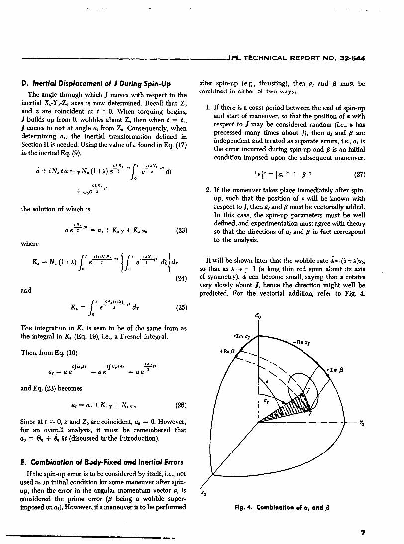
D, Inertial Displacement of J During Spin-Up after spin-up (e.g., thrusting), then as and B must becombined in either of two ways:
The angle through which ] moves with respect to the
inertial Xo-Yo-Zoaxes is now determined. Recall that Zo 1. If there is a coast period between the clad of spin-upand z are coincident at t = 0. When torquing begins, and start of maneuver, so that the position of • with] builds up from 0, wobbles about Z,, then when t = t,,] comes to rest at angle as from Zo. Consequently, when respect to ] may be considered random (i.e., _shasdetermining al, the inertial transformation defined in precessed many times about ]), then al and B areSection II is needed. Using the value of found in Eq. (17) independent and treated as separate errors; i.e., at is
_' the error incurred during spin-up and/3 is an initialin the inertial Eq. (9), condition imposed upon the subsequent maneuver.
a+iNzta=rN'(l+X) e'_ Joe _- _'dr !elZ=!asr-+I/31 _ (27)
_x_, t_ 2. If the maneuver takes place immediately after spin-+ _ooe--7--up, such that the position of z will be known with
the solution of which is respect to J, then af and/3 must be veetorially added.In this case, the spin-up parameters must be weU
.v, defined, and experimentation must agree with theoryt2
a e _o = ao + K3-¢+ K, _,o (23) so that the directions of as and/3 in fact correspond
where to the analysis.
/o 1t i (I+A) b'z "r:z ..... "_2K3 = Nz (1+ X) e_ e 2 d_ dr It will be shown later that the wobble rate _ (1 + X)So,
so that as x--_ - 1 (a long thin rod spun about its axis
(24) of symmetry), 4: can become small, saying that • rotatesvery slowly about 1, hence the direction might well be
and predicted. For the vectorial addition, refer to Fig. 4.
t iN..- (l+_t) T*
K, = e---_"- " d, ('2,5)Zo
The integration in K4 is seen to be of the same form asthe integral in Ka (Eq. 19), i,e., a Fresnel integral. +rmaz
.Reax
_t2t fw_t i.f_,tdt iy,al = ae = ae = ae 2 _ _, _Iml3
and Eq. (23) becomes
at = ao + K._7 + K_ _, (26)z
Since at t = 0, z and Zo are coincident, ao = 0. However,
for an overall analysis, it must be remembered thatao = Oo + 0oat (discussed inthe Introduction).
E. Combination of 8ody-Fixed and Inertial Errors
If the spin-up error is to be considered by itself, i.e., notused as an initial condition for some maneuver after spin.
up, then the error in the angular momentum vector as is Xoconsidered the prime error (/3 being a wobble super-imposed on a,). However, if a maneuver is to be performed Fig.4. Combinationof at and/_
_ 7ii mm
1965008264-013

JPL TECHNICAL REPORT NO, 32.644
Since at = # (cos 4, + i sin 4,)when 4, = 0 (standing on the which can be_verified by substitution. The final form of
Xo axis), an observer sees _ al = O,consequently it is just the K's is reached by getting rid of the clumsy design
that component which is then projected onto the Y,,- paraineter N:. Note that, for constant N..,
direction (in this case -0, since 0 is defined counterclock-
wise). The same is trine for c),_ a;, but no sign change is N: = So�t1
required. # is defined in the normal way. Hence, in
Fig. 4, a unff sphere is superimposed on the vector dia- Then, by substitutiongram, and the angular components are shown projected
on the sphere. It can be seen that 1 2 1-_2N:tl = _-Sotl,
and the four K's assume their final form
_R.c = _.# + 3,.a,
• , I'%# T
whence x_o ta ix,_ ,:jo i__ :
K: (t,) = e ; e = du
E = B - i at (9_.8) (29)
and ] E I is the required error.1 iJl So it
Ko.(t ) =_--e =(1 + x)s. (30) '_A discussion of the errors defined above follows, with
examples given for E,/3 and as. _ ___+-xi-.:.,,; c-x-
---'_ dxdu
K, (t,) = Ir_]_Jo e, eF. Discussion of Integrals
In order to solve numerically Eqs. (17) and (26), the (31)
quantities K_, K:, K_ and K, must be evaluated. In allcases the variable is t where 0 < t < tt. As mev.tioned _[,. ,+x, t,_ _ _#----;previously, K, and K, are Fresnel integrals, and the double [ _t_ /" i,---_ du
integral in K_ is the integral of a Fresnel integral. To get K, (t_) = _] (1 + ,t) so Jo ethese integrals in familiar form, a change of variable is
required. The usual argument in the exponent of the (32)
Fresnel integral is i_-'/2. Hence, ff this substitution is
made in K1, Ka and K_, they become When the shape of the body is stipulated, and the spin-upparameter so is given, then the values of K = ] (t_) may
x/-x_tx.v= be determined, and the errors may be calculated with
,_x, , /'%1.' assumed values of -t and _o. As an illustration, Figs. 5f-KI-
KI (tl)= .tJ_ eFltle _ u, du ' through 14 show the K's as functions of tl for a few com-_/^°o Jo binations of x and So.
I'YF,_-xl F'I- ,,_.XJ-"--;--,, ¢_/_-_ The Fresnelintegralsof/1 andK, areof the following
t I + _ I i_Y_',2 t _" 2 form (see, for example, Ref. 4):
K_ (t_) = _r_i_J, e, Joe-," dx du
f.C (v) = cos_ u"-dufrG,(1-rzx5 ¢pI
,, ,-7;7"
am
i ii ii m
1965008264-014
l
JPL TECHNICAL REPORT NO. 32-644
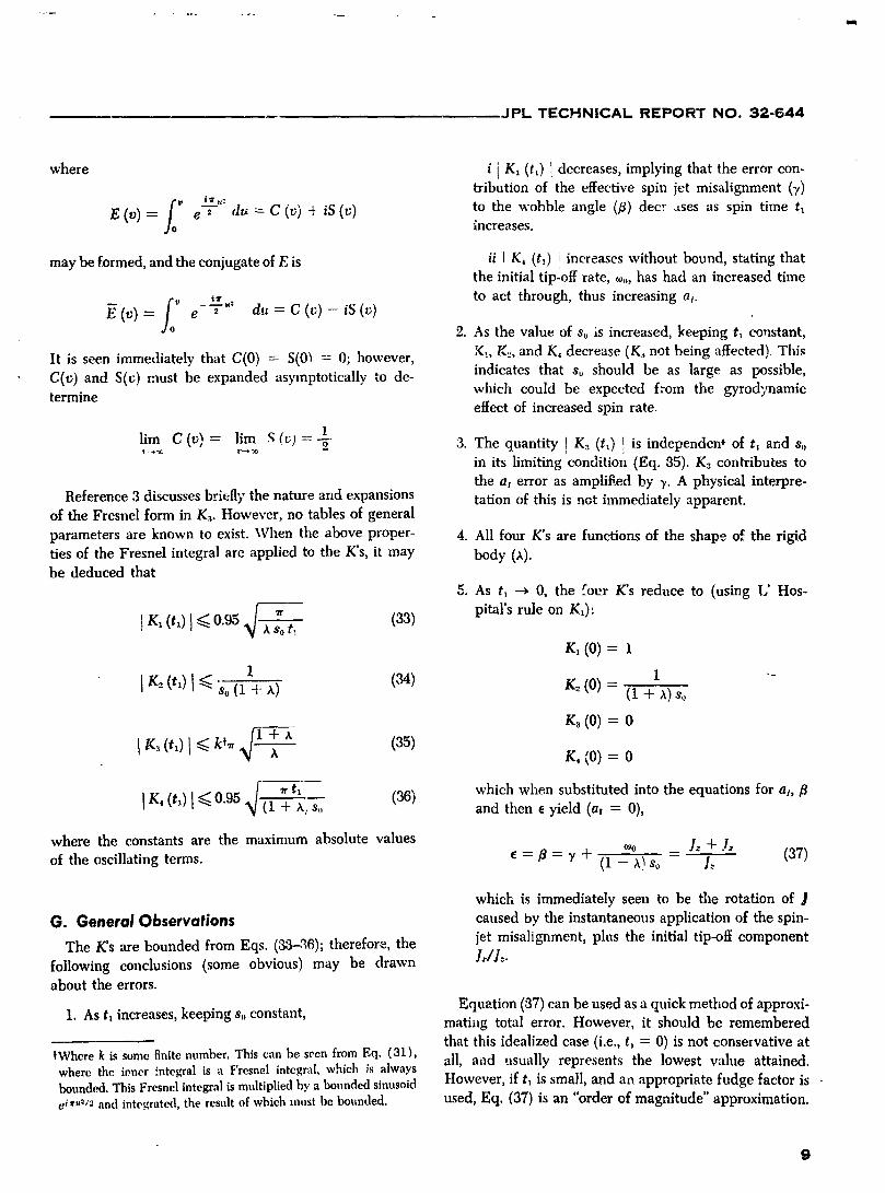
where i i K_ (tl) 1 decreases, implying that the error con-tribution of the effective spin jet misalignment (y)
E (v) = e--C- du = C (v) _ iS (v) to the wobble angle ([3) dec, _tses as spin time t_hlcreases.
may be formed, and the conjugate of E is ii I K_ (tt) i increases without bound, stating thatthe initial tip-off rate, _oo,has had an increased time
__._.: to act through, thus increasing al.g(v)= e _ du=C(t;)-iS(v)
2. As the value of So is increased, keeping t_ constant,
It is seen immediately that C(0) = S(0_ = 0; however, K:, K..,,and K, decrease (K_ not being affected). Thi.¢
C(v) and Sly ) must be expanded asymptotically to de- indicates that so should be as large as possible,which could be expected from the gyrodynamic
termine effect of increased spin rate.
lim C(v)= lim S(v)- 1........ 2 3. The quantity I K3 (t_) ! is independen* of t_ and Soin its limiting condition (Eq. 35). K3 contributes to
the a_ error as amplified by 7. A physical interpre-
Reference 3 discusses briefly the nature and expansions tation of this is not immediately apparent.of the Fresnel form in K._. However, no tables of general
parameters are known to exist. When the above proper- 4. All four K's are functions of the shape of the rigid
ties of the Fresnel integral are applied to the K's, it may body (,_).be deduced that
5. As t_ --->0, the four K's reduce to (using L' Hos-
] K_ (t_) I <_ 0.95 so t: (33) pitars rule on K_):
r, (0)=I I "-
I K=it,) l So(1 + x) (34) r, (0)- (1+K_ (0) = 0
4[ K_ (t_)l _ k_r + x (35)x K, (0)= 0
_ t_ (36) which when substituted into the equations for a, flI K, (t_) I _ 0.95 (1 + x, s,, and then e yield (a_ = 0),
where the constants are the maximum absolute values _oo - 1" + ]" (37)of the oscillating terms, e = fl = y + (1 - X)so 1_
which is immediately seen to be the rotation of ]
G. General Observations caused by the instantaneous application of the spin-
The K's are bounded from Eqs. (33-q6); therefore, the jet misalignment, plus the initial tip-off component
following conclusions (some obvious) may be drawn ]J]="about the errors.
Equation (37) can be used as a quick method of approxi-
1. As t_ increases, keeping s. constant, matiag total error. However, it should be remembered
that this idealized case (i.e., t_ = 0) is not conservative at
tWhere k is some finite number. This can be seen from Eq. (31), all, and usually represents the lowest wdue attained.where the loner :'ntegral is a Fresnel integral, which ,_salwaysbounded. This Fresnel integral ismultiplied by a bounded sinusoid However, if ta is small, and an appropriate fudge factor isci_,_I2 and integrated, the result nf which must he bounded, used, Eq. (37) is an "order of magnitude" approximation.
9
1965008264-015

JPL TECHNICAL REPORT NO. 32-644
H. Limiting Cases ,_, = _ sin#cos_ - Osinq_
1. _, --- 0 (sphere). The values for the K's are (using o,_= _ cos 0 +
L'Hospital's rule on KI and K_) Referring to Fig. 1, it may be stipulated that the initial
K1 = 1 conditions at t = 0 are
K_ = 1�So ¢b= O _ = 0
0=0 d---doKs=i 1-e-q--j q_=0 _=0/
= coo_=Oo ; oJov=O ; _oz =0and the errors are
where
B =')1 + _Oo oJo = t%x + iOov = _o.8o
a_ = i'/ 1 -- e _ )+ *,°_/ so whatever direction the tip-off occurs in, defines the Xo-Yodirections.=/3 -/ai = c_ + i_ _r
•, = ,_ 2 - cos_ + oo + S d. Numerical Evaluation of Errors
_/ So As mentioned in the Introduction, the two cases of
t_ l interest in this Report are the Apollo-shaped capsule andso t, _ C the Ranger landing capsule. Since the K's need only the
Ev = -_ sin _ - 0,o_/ So body shape x anct final spin rate so to be evaluated, it
Notice that the _ in the numerator of the second was decided to keep the error sources eo and 7 strictlyterm of a_makes _ divergent when _o =# 0. As t, -* 0, parametrical. Spin-up time (t_) is taken with wide enoughE =/3, the value of Eq. (37). bounds to encompass most situations. The values used in
determining the K's are the following:2. x = - 1 (thin rod). As X--* - 1, K2 increases without
limit (K, is finite because (1 + x) appears in the upper APOLLO RANGERlimit of the integral), the other K's being bound.This means that spinning-up a long thin rod about x 1/3 -8/4
its symmetry axis (I, = 0) when an initial tip-off Final spin rate, rad/sec (s,,) 1, 2, 5, 10 30rate is present, is highly unstable. This is intuitivein that if I, = 0, there is no spin momentum to Spin-up time, sec (t,) 0--10 0--3counteract the tumble of the rod.
3. x = + 1 (fiat disc). AsX_ + 1 (its maximum value), Plots of both the real and imaginary portions of K,, K:,the coefficients of the K's are minimized, indicating K._and K4 vs t_ are given in Figs. 5--14.that for a given spin-up time and rate, an infinitelyfiat disc is optimum. This is obvious from gyro- The numerical evaluation of K1, K,_and K4 was, at first,dynamic considerations, very frustrating. Fresnel integrals are known for their
difficulty in approximating over a large range of argu-ments. However, the excellent orthogonal polynomial
I. Initial Conditions (Chel:yshev) approximatiot, given in Ref. 6 is satisfactoryfor K_and K,, while the corresponding function-generating
The relationship between the initial tip-off rate (tOoand0o)is found from Eu!er's rate transformations (Eq. 8) polynomials were of sufficient accuracy for Ka. Asymp-
totic expansions for Fresnel integrals and for integrals of
tO:_ _ sin _sin _k+ d cos _ Fresnel integrals are given in Ref. 4,
_n
1965008264-016

JPL TECHNICAL REPORT NO. 32-644
One numerical example should suffice in illustrating 3 o
the use of the K's in Figs. 5--14. Recalling Eqs. (21), (26),
and (28)
B = K_7 + K2o,o zo r,
at = K:, 7 + K, (o,,
E = B - i as _" I.Qo
3.G
2.(1
__ 0 2 (_ 4 0 6 0 8.0 I0.0
tI, sec
I.o Fig. 7. Real parts '_f K_, K,_,K3and K4vs tl(So= 2rad/sec, A = + 1/31
,.o
_,.o I ,.o
Fig. 5. Real parts of Ka, K_,/(a and K4vs tl _ i o
(So= 1 rad/sec, X-- + %) _ /
30 1 o -I ""_C
I2C ."_ -,.o I
0 2 0 4 0 6.0 II 0 10,0tI, sec
Fig. 8. Imaginary pa_s of Ka, K2, K3 and K; vs txHEI.o KL (So= 2rad/sec, X = + l/a)
j____ __ For Ranger, the specification for y is O.OO6 rad with a
, spin-up time of 1.0 see? If an initial tip-off rate ofi 0) = #o = 0.005 rad/sec is assumed (realistic), then from
i Figs. 13 and 14,
-"°I _o ,!o ,,o _o .o.ot I , SeC
OAeronutronicPublication U-9_00,Final Technical Report-LunarFig. 6. Imaginary parts of g_, K2, K:, and g_ vs f_ Rough Landing Capsule Development Program, Newport Beach,
(so = 1 rod/see, _, -- + 1/sl Calif., pp. 3-28.
!1
1965008264-017

JPL TECHNICAL REPORT NO. 32-644 ....
.,o ! 1
i2.0 _"
i
r
o-I.C O 2 0 4.0 6_0 8.0 10.0 -I 0 2.0 4.0 6 0 8 0 I0.0
fl, sec /,, 5ec
Fig. 9. Real parts of K,, Kz, K3 and K, vs tl Fig. 11. Real parts of K1, K2, K._and K, vs tl' (so = 5 rod/see, ,_ -- -t- I/3) (so = 10 rad/sec, _. --- -I- 1/3)
3.0 ! 0
-I ff -I
0 2.0 4.0 6 0 El.0 10,0 0 2 0 4.0 6 0 B 0 10,0
Fig. 10. Imaginary parts of K_, K:, K3 and K4vs tx Fig. 12. Imaginary parts of Kx, K:, K._and K.,vs tl(So= 5 rad/sec, _. = "t- 1/3) (so = 10 rad/sec, ,_,= -t- 1/3)
_BeK1 = - 0.208 Re K2 = + 0.034 where
_, K:, = -- 0.238 £Q,K, = +0.263
,q,z K_ = -t- 0.094 _q,,_K_. = + 0.129 /3 = - 0.0011 + 0.0012 i and a_ = - 0.0001 + 0.0062 i
,%, K:_:: + 0.671 ,.q,, K, = + 0.438 and e = 0.005 + 0.001 i and I _ ] = 0.005 rad
12
I
1965008264-018

II
JPL TECHNICAL REPORT NO. 32-644
IV. THRUSTING OF SPINNING SYMMETRIC RIGID BODIES 7-
A great deal of work has gone into analyzing the effects with the angular momentum vector, ]1o, and the Yo axisof rocket thrust misalignment on accelerated spinning is along the dircction of -_,, (coinciding with the 0 direc-
bodies. References 4 and 8 are the classic works, done tion when ck = 0; see Fig. 1).during the 1940's, primarily on spin-stabilized rocketslaunched from launchers with and without fins. The First to be determined in this Section is the angle of
basic theory used in this Section is a combination of these attack, aj, of the thrt, sted rigid bod; "1'. This inertial angle
and other referenced works. No claim is made to origi- of attack defines the position of the thrust vector as anality, except, perhaps Eq. 67. function of time. The thrust vector is then integrated
The one design parameter which is common between lOThus,the error between Zo and ] of Section III, al, is subtractedthe last Section and this Section (except shape of the out here. Of course, this error m,lst be considered, and is dis-
body, X) is the design spin rate s,,. An output of Section cussed in Section VI.HThis a_differs from that in Section III in that (a), this a_is in a
III, the wobble angle Bo, along with s,,, is used as an different time domain since the Xo,Y,,,Zoaxes arc ledefined wheninitial condition here. The inertial axes X<,-Y,,-Zo are rede- t--=o and (b), the a_here includes wobble angle. Hence, aso=zOofined for this Section. When t = 0, the Zo axis coincides when t = 0.
13Ul ii i i
1965008264-019
JPL TECHNICAL REPORT NO. 32-644
into velocity, and the resultant error in both the magni, here, and p, a measure of the misalignment, is estimatedrude and direction is coz_sidered. There are certain sim- by _ to the accuracy of small angle approximations.
plifying assumptions made throughout this Section, such Appendix C contains data on the effective thrust misalign-as constant mass, inertia, etc. A discussion of the effects rnent from the 2nd and 3rd stages of the Scout launch
of these assumpti_ms is found in Appendix B. vehicle. This data was used in the numerical evaluation.
It is also required that the thrust vector intersect the
A. Thrust Misalignment roll axis, i.e., no roll torque is present. If this is not th_
Thrust misalignment, which can be defined as the case, then nonconstant effects on spin rate during burning
lever arm through which a given thrust acts, gives the must he considered, which make the differential equa-body both a rotational and a translational acceleration, tions nonlinear (see Appendix B).The translational motion will be neglected in this Report
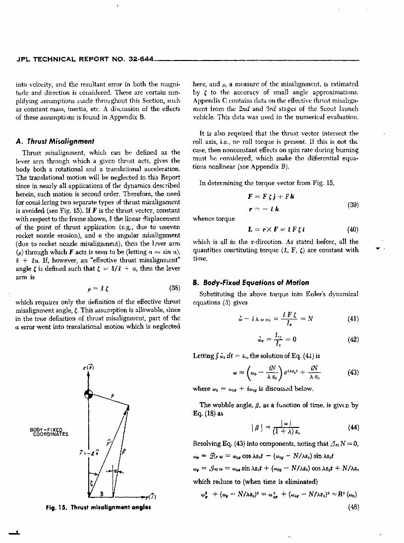
since in nearly all applications of the dynamics described In determining the torque vector from Fig. 15,
herein, such motion is second order. Therefore, the need F = F _ j -t- F k
for consi,tering two separate types ,of thrust misalignment (39)is avoided (see Fig. 15). If F is the thrust vecter, constant r = - _ k
with respect to the frame shown, 8 the linear -Jisplacement whence torque
of the point of thrust application (e.g., due to uneven L = r× F = _ F _ i (40)rocket nozzle erosion), and a the angular misalignment
(due to rocket nozzle misali_;nmeut), then the lever arm which is all in the x-direction. As stated before, all the
(p) through which F acts is seen to be (letting a _ sin a), quantities constituting torque (_, F, _) are constant with =" •8 + let. If, however, an "effective thrust misalignment" time.
angle _ is defined such that _ = 8/_ + a, then the leverarm is
B. Body-Fixed Equations of Motion
Substituting the above torque into Euler's dynamical
which requires only the definition of the effective thrust equations (:3) givesmisalignment angle, ¢. This assumption is allowable, since
tF¢in the true definition of thrust misalignment, part of the o_- i x o__z - - N (41)a error went into translational motion which is neglected I_
. _ L.. _ 0 (42)(05_ iZ
Letting J"o3,dt = so, the solution of Eq, (41) is
= \=° - xSo] + --xs,, (43)where o_o= o_o_+ io_0_is discussed below.
_ _"__ P The wobble angle,/3, as a function of time, is giv_.n by
gEq. (18) as
BODY-FIXED I fll (I .L _.)$oCOORDINATES
Resolving Eq. (43) into components,noting that _t N = 0,
_, = _ = = OJo_cos XSot - (O_ov- N/Xso) sin ;,Sot
o_ = _q,, = = =o_sin Xsot + (=or -- N/Xso) cos Xsot + N/xso
which reduce to (when time is eliminated)
' + (=,- N/o) == " + - N/Xso)=a=:y(7) %' =o_
Fig. 15. Thrust mi=alignment angle= (48)
1965008264-020

I
JPL TECHNICAL REPORT NO. 32-644
my _;-- iX _, = N -= 0 (4)
/_,_(_o_j oJ= (0-, i_sinS)e -iv' (8a)
'Faking the time derivative of Eq.. (80) du.d .inserting the
___/v initial conditions, i.e., O= Oo,q_= q_o,_ = _o, _ = O,_ = O,and_ = 0,
m/_£fl 4, sin Ov(_o 4- a. tOoz)= 0 (50)
which has roots of 4, --=0, 0o= 0 and _o.... x o_o_.If G = 0,
'mr(OUT) % there are no initial conditions (since there is no wobble).If 0o_ O, which necessarily implies that q;o--/=0, then
Fig. 16. Body-fixed rates of a symmetric body _o = "- ),_o_for Eq. (50) to hold, and when this value for -with torques _ois substituted into Eq. (49),
which is a circle with its cent'_r at (0, N/xs_), and a radius _o - (1 + ?,)so (51)COS 00
of R(_,o)= {%, 4-(toou- N/xso)'}k The complex radius and Eq. (9) becomesvector, _(t) rotates around the circle at an angular rate
XSo(see Fig. 16). Since the coordinates are body-fixed, _o = 4,00o= i(1 + x)So 8o (52)the angular momentum vector (1) and the angular ve-locity vector (12), .which are coplanar with-g_, rotate for small 00.about the axis of symmetry of the body. "-'-
D. Complete Inertial Transformation
C. Initial Conditions Now the value for a_ (the inertial angle of attack) can
Certain relationships among the Eulerian angles need be determined. Equation (9) stated that a + i so a = w,to be derived before initial conditions can be stipulated, and when the value for _ (found in part B) is substitutedJust before ignition of the rocket motor, the spinning and the differential equation is solved, the result isbody has no torques acting upon it, and the form in which
given that when t = 0, _ - _o, _,o.-= So, 0 = 0o = /3 s o(from Section III), and 4;= ¢bo(precession rate). Needed is
_o = _o.-+iwo_ in term_ of the given quantities. Without N {1- ei'°t}loss in generality, the other Eulerian terms 0, ¢b,¢_are xs_zero initially. The proofs that 0 = 0 and _ = constant vail (53)
not be given here. The Eulerian angular transformations, and from Eq. (10),Eqs. (8) are
COo_= 0 al = a _ifto,dt = a e "_s°t
_Oov= 4,0sin G _ _o 00 (49) Letting _o = i (1 + X) so 0oand ao = a,o = 00, Eq. (53)becomes
4, • .So=(Ooz=': oCOSOo+ o_o+qJo
whereupon a_=0°+{_2o Nx(x+I) 0°}{ 1 - e'tx 0#ì*X�•�}_o = '_o,+ i _ov= i _o 0o .-
Since it is the sect, nd order differential equations - ?'s-'_'°1 - e_'°t
(_ = d_-_/dtL _ some angular displacement) that are of (54)interest, only two initial conditions must be stipuiaw, d(so, G). Hence, some relationship must exist between sso Without going into too much detail at this point of theand Soand G. This can be found by eliminating _ in Eqs. development, it can be seen that at is the sum of two
(4) and (8a) when t = 0 and N = 0 and initial conditions sinusoids of differing amplitudes and frequencies. Theexist, frequency so is the spin frequency, and (! + _) so is seen
15 k
1965008264-021
JPL TECHNICAL REPORT NO. 32-644 .......
from Eq. (51) to be _o, or the initial precession rate if vector (F) is given in Eq. (89). If a small angle approxi-cos O__ 1. Tile amplitude of the first term can go to zero mation is made for 0, then the inertial thrust vector, F'.if N counteracts the wobble angle, _,,.However. this only resoh'ed into its coordinates from Eq. (55) above, isnulls the amplitude to the precession part, and does not_'at_e al to go to zeib. I[ 0. = 0, the amplitudes of the two F" --- - F _;(cos, sin _ + cos _ksin ,) + FOsin,
sinusoidal terms differ by a factor of (x.+ 1), which is F_ -F_ (sin ,sin ¢,-cos, cos _) -FOcos,bounded by 0 and 2. It will be. seen later that if 0o_- 0,then it can become a predominate term. F" = F ._0cos _ _LF cos 0 (57)
The cos 0 is retained in F" for later consideration.
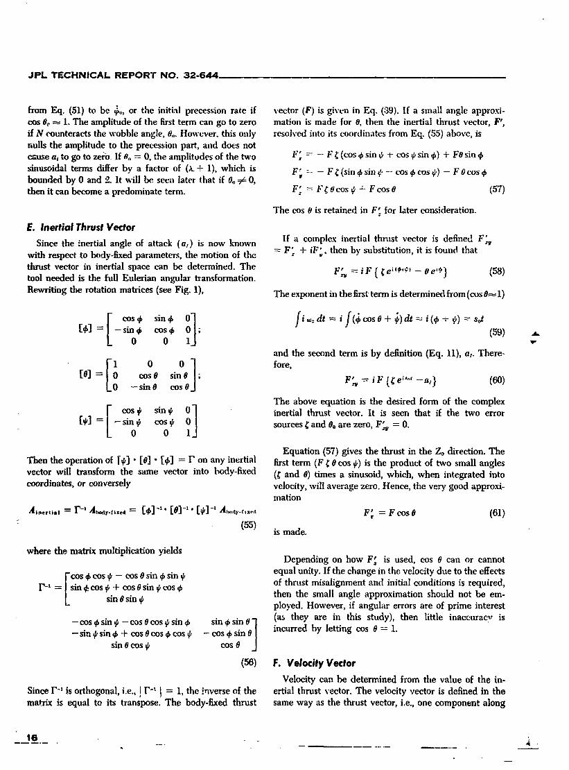
E. Inertial Thrust Vector
Since the inertial angle of attack (a_) is now known If a complex inertial thrust vector is defined F_with respect to body-fixed parameters, the motion of the = F_ + iF',,, then by substitution, it is found thatthrust vector in inertial space can be determined. Thetool needed is the full Eulerian angular transformation. F_ = iF { ¢e_(_+¢_-O e '.6} (58)
Rewriting the rotation matrices (see Fig. 1), The exponent in the first term is determined from (cos 0_1)
['] = l--sin'L Or cos' cos.Sin'0i] ; fi.:dt=if(ibcosO+(,)dt=i(,+_)=Sot (59) .a_and the second term is by definition (Eq. 11), a. There-
o o] or[01= cos0 an0 ; = iF e"o'-.,} (6o)-- sin 0 cos O
The above equation is the desired form of the complex
F cos_ sin_ 001 inertialthrust vector. It is seenthatifthe two error[9] = | -- sin _ cos _ sources _and 0oare zero, F_ = 0.i]L 0 0
Equation (57) gives the thrust in the Zo direction. TheThen the operation of [_] • [0] • [_] = 1-'on any inertial first term (F _ 0 c_)s_k)is the product of two small anglesvector will transform the same vector into body-fixed (¢ and 0) times a sinusoid, which, when integrated intocoordinates, or conversely velocity, will average zero. Hence, the very good approxi-
mation
A,,..,,., = F-, = [,]-,. [0]-,. F" = F cos0 (01)(55)
is made.
where the matrix multiplication yieldsDepending on how F_ is used, eos 0 can or cannot
['cos, cos 9 - cos 0sin, sin _ equal unity. If the change in the velocity due to the effects1"-t = |sin _ cos _ + cos 0 sin _ cos, of thrust misalignment anti initial conditions is required,
k sin 0sin _ then the small angle approximation should not be em-ployed. However, if angular errors are of prime interest
-cos,sin,k-cos0cosCsin, sin,sinO'] (as they are in this study), then little inaccuracy is- sin ¢ sin, + cos 0cos, cos _ - cos, sin 01 incurred by letting cos 0 = 1.
sin 0cos _ cos 0 ]
(56) F. Velocity Vector
Velocity can be determined from the value of the in-Since ITM is orthogonal, i.e., ! I"-t I = 1, the inverse of the ertial thrust vector. The velocity vector is defined in thematrix is equal to its transpose. The body-fixed thrust same way as the thrust vector, i.e., one component along
16---. _ ,
1965008264-022

JPL TECHNICAL REPORT NO. 32-644
the inertial Zo axis, the other component defined in the then reducing,complex cross plane.
., = A._ e i,*t -- 1v _ m F', dt v_, _ s,,
'°" [ , . ][ ]• = g--_[' F: dt -_ x(x+l)-'so (x+l)so e"o"_" - 1v_ mJo .
where _ is the average mass of the body during thrusting + itN Iand g ---32.2 ft/sec". If mass cannot be assumed constant, (1 +X)s_ (63)
then the integration of Eq. (62) must be done numerically.
Equation (63) is the derired form of tile cross velocity.
Then, from Eqs. (60) and (62), Breaking v_ into its coordinates reveals its character.
v _"= _(_, vxv'"= C_ cossJ -i- C.,coss,,(l + x) t. - (C,+C2)
o',= m iF (_e"*' -a,} dtov"= _d,_t,,v" = C_sinsot + C_sinso(l+x)t_ + C_t
which is, when a_ (Eq. 54) is substituted and inte_ated, where the C's are the constants in Eq. (68). The aboveare seen to be modulated sinusoids, the first with a con-
stant bias, - (C_ + C:), and the second with a ramp• _ igF - _ (e i'*t - 1) function (C_ t) impressed over it. The general form of v'.
and v_ is shown in Fig. 17. In the plots, either _, _ - 1iA _nd C2 >>C_ or x _ + 1 and C_ >>C_.. If X _ 0, the quail-
So(1-t-x) (e'_°"'x_t - 1) tative solution shown is not valid.
Plots of tf_ vs v'. are shown in Appendix B. These cor-+ /B(e_'Otso - 1) - (A- B- 00) roborate the cross-plotting of Fig. 17.
where, temporarily, If cos 0 _ l, the integration of vj is straightforward.
A - _,(x+ 1)s_ 0oand B - aso2 o'_ = __ff F_ dt = -_ F dt = m (64)
(o) (b)
a
vx vy
Ci+ C_
t to o
Fig. 17. Shape of crossvelocities V: and Vv
17
1965008264-023

JPL TECHNICAL. REPORT NO. 32-644
However, if the small angle approximation cannot be 2
made, i.e., the change in v" is desired, then o,b
, gf, gFf, (O5) ,o, = .--_ F cos Odt = m Jo
and numerical integration ".'snecessary, v,
G. Velocity Dispersion ,If o,_ = 0 due to the absence of initial conditions and _ _ \ ro
thrust misalignments, then the resultant velocity would o_ r
lie enP,cely upon the Zo axis. When v,_- 0, the tip of theresultant velocity vector is moved from the Z_ axis (Fig.18) at an angle
• • Fig.18. Velocitydispersionanglesa = tan-1%, o. (66)
and is treated as a random variable because of the ran-
a is seen to be the velocity dispersion angle caused by domness of the 0odirection with respect to the true iner-
the presence of a cross velocity, v_. The final value of u tial system defined in Section VI. If it is required, it is-1 t I
is reached when the time t = tn, the burning time of the seen from Fig. 18 to be tan (%/0,).r,3cket motor.
The wobble at the end of burn can be considered an
output error. If this is denoted by/3], then from Eqs. (43)Equation (66) is expanded to (with the use of Eqs. 68 and (44),
and64)I-I N
I 11::2T -)So- 0o x(x+1)s: (68)= T -
T-is seen that ff - 1 < _, < 0, i.e., I, > I:, then the fight
_( N 0o )( ) term is negative and , fix , > 0o.N itself is always defined+ X(X+l)2s_ (h+l)so eia°"'_)t--1 positive (the worst case).
iN Another error which might be of interest (neglected+ (l+a)s_ here) is the error in the magnitude of the velocity vector
(67) (a is the error in direction). The value of v' is obtainedfrom Eq. (65); the odd term appearing in Eq. (57) (i.e.,
It is seen from Eq. (67) that if N = x (X + 1) So 0o, F, 0 cos _) still being neglected. This v" is compared to
the precession amplitude vanishes. The spinning ampli- the value of the velocity had the thrust always beentude can furthermore be nulled if the thrust misalignment applied along the Zo ax_s,AV_= CIn (m_/ml), c being the
= 0o (1 + X)/e0, but the bias term, N/(1 + x) s2, re- exhaust velocity of the gases, m_ the initial mass beforemains. Only if ¢ = N = 0o= 0 does a(t) = 0 for all values thrusting and m/the final mass when t = tb; i.e., m_ -- mr
= mass of propellant expelled. The difference in magni-of t. rude of the two velocity vectors has been less than 1%
for the range of parameters the author has dealt with.Of prime interest is the magnitude of a, i.e., ]a ] = This means that the initial conditions and thrust misalign-
(_R,_a + _qm2(t)v'. The radial direction of a with respect ment cause less than 1% of the linear momentum of theto the inertial system (angle ,/in Fig. 18) is of no interest rocket motor to be changed by spinning.
1965008264-024

, JPL TECHNICAL REPORT NO. 32-644
H. Limiting Cases Figure 19 is a plot of a= vs so tb/or seveJralvalues of
formationAclose inspection of Eq. (67) yields the followingin-abuuta: (_,_)
1. Taking limits on t . At the other extreme (as t grows small), afterL'Hospital's tale is applied
As t grows very 'a_ge, limlal= ao = ]_--00 ! (71)too
limlct[= a= (l+,_)s_ I_ (69) which is evident from the position of the thrustvector at l = 0 with respect to the inertial Z, axis.
recalling that N = FJtUI,. Hence, after t gets verylarge, a approaches a constant value which is in- 2. Taking limits on _tversely proportional to spin-rate squared, and directlyproportional to acceleration (F/m). This can be a As x--* 0 (_bere), a Elows up in both the firstuseful approximation if the body goes through two coet_cients (Eq. 67), as would be expected,enough revolutions, so that the amplitudes of the sivce a sphere has no body-Exed gyrodynamic sta-first two terms in Eq. (67) are small compared to bilitT. However if t _ _: at the same time, the re-a=. If the parameters are further broken down, it s_ts of Eq. (69) arecan be seen that F = Ir/tb where lr is the total im-pulse of the rocket motor, and tb is the burning time. N
Ir is a measure of the velocity requirement (since tb x-.ohm{ limt.._a } = _s_ ;is a motor parameter). When the above value forthrust is substituted into Eq. (6xJ),the result is the same result is obtained ff the limits are taken
in reverse order and L'Hospitars rule is applied. If
= ( It1!; _ 1__ t -> 0 as X-->0, from Eq. (71),\ h /gt (70)
lira { lim a }= le--0olk-_ O t-.)O
I000_ _[" I i ! As _ -1 (thin rod), the second an(]-_,ird terms6oo , I ] of Eq. (67) blow up and c&dse divergence of a. This
4oo _ ""N__ [ I I also can be anticipated, since when x = - 1, I= = 0,
_- __' '_I 'r._ and there is no angular momentum generated along
_K =o.z5 A":_ the z-axis to counteract the effect of thrust mis-200 -- _ I .....
=0.20 I alignment.I I
lao _ \ N_ --K = 0.159(APOLL0)
\ _ _ . When X--->+ I (flat disc), the three coeff;cients inoo , \\ "_ N_'N_ Eq. (67) are minimized with respect to X, thus min-4.0 N k
- x': 0.I__)_ _ _ _ imizing a (t). This results from the maximum mo-_2.o , ,_ \, \_,_ mentura developed in the z-dir,_.cti°n •
K= 0,0
io [ _'_ ' \ \\N 3. Taking limits on soo.eI- ' \ \ \\\
\\._'\ NNN If so")O, a divergent form of Eq. (67) appears.0.4
' __N_ This, however, is not indicative of the case since
0z l NXX,X,X_ the small angle approximations no longer hold. Ap-. pendix D treats this special ease.01 I I, z 4 ,o zo 4o6o,oozoo4ootoooS,2tb/_s¢ As So-'_ co, the resultant error a(t)--_ 0, since in-
Fig. 19. a= vs so= t_for st,veral values of g finite stability is being approached.
19
1965008264-025

JPL. TECHNICAl. REPORT NO. 32"6A-A-
I. Maximum Envelope of Solutions
If the constantcoefllcientsin Eq. (67) are denoted K,, \
K_ and a® respectively, i.e.,: ao
\ Eq.(75)K; (e,,._o., _ 1) + i a®a= (e".t-1)+T
(79) _ (67)
the real and imaginary components of a may be written
K," = _" " T C°Ss°t L I. _ I _ "f _"= ____ _--_-----T -_/----V- 7
°- I, V ;/ V!
E,at = _q,na = T sinSot Fig.20. Maximum envelopeof solutions
+--T-K2sin So(1 + x)t + a_, ('73) The dashed lines are the real solution of Ia(t) I in Eq. (67). w-It is to be noted that the body should go through atleast 3 revolutions, i.e., sotJ'2_. > 3 for this envelope
If the maximum values of the sinusoids are chosen in approximation to be valid.such a way that if both Kt > 0, K2 > 0, or both K1 < 0and K2 < 0, (a**is always > 0), then
±2 J. Some Examplesa,, < T (K, + K._) A few examples are given of the results in this Sec-
tion. The basic parameters will be the same as those ofai < _ (KI + Kz) + a® (74) the last Section, i.e., Apollo and Ranger capsules, same
/,
spin-rate, etc. The error output of Section III is used asan input here (wobble angle 0o).Table 1 lists the peTti-
er ff Kx < 0 while K: > 0, then, ment data. The results are shown in Figs. 21-27.
2at < T (K_ + K_)v_ Table 1. Basicparameters
1 (K_ - K,) + a_ (74a) Ap,., ea,ge,a_ <T_" +216.4 - 5_oo,
The maximum magnitude of a will then be given by -m,ooo.-- 20°000
Ia(t) 1< (ag + a:) _ (7_) Thrust misallgnmentr, rod 0.004t 0.004tRocketburn tlme ts, suc 5.0 9.6
If Eq. (74) is substituted into Eq. (75), it is seen that Capsule shape X '11 --_i a (t) 1is a fourth order polynomial which approaches a
Initial spin rate, So,rod/set 1 2 $ 10 30hyperbola as a_ _ 0. The curve at the point t = 0 has asingularity, and thus must be mated to the la (t) i axis Initial wabble angle 00, rod 0.025 0.013 0.005 0.003 °" 0.001"*
at ao.Figure 20 shows how the envelope of ] a(t) Ibehaves.ti dg
*g = _, e catch-oil term orhin@out of Eel.(67).
tThe K's used here are totally independent of those used in Sec- "'lm.d on output, of _ttle. III.
tion III, and are the result o,c an unfortunatechoiceof symbols, ts.. AppendixC.
2O
1965008264-026

• JPL TECHNICAL REPORT NO. 32-644
°°'4' ' i i'__tl i0.019
o -/ _ ooo,0_ ,-- o.o_4 '_ \/ _, .
.... i
_/'_' \ / __°°°'°\o.oo, I '_ / "_ /1 _'-
't . _ 1 '; tl --.
0.004 0 I I 2 3 4 5
Fig. 22, _ Itl vs t for Apollo-shaped capsule o 2 4 5So= 2 rad/sec, P. = 0.012 rad TIME,sec
Fig. 24. _ It) vs t for Apollo-shaped capsuleSo-_ 10 rad/sec, 0o = 0.003 rad
21
1965008264-027

JPL TECHNICAL REPORT NO. 32-644_
oo ,o 'l i °°'I Ei Ii I
I !o.oos2s ! o 0t0 t i.. ]
t
='o0o_ 00o5 1- f I 4
__ i i , fi , 1 II ' 1
ooo:,'r5 oo 1 1 [ I1.92 3.84 5._ l7.68 9.60
TIME, sec
Fig. 26. a (t) vs tfor Ranger capsule K = -- 10,000
000150 0 1.92 384 5.76 7.68 9 SO
T_._,_E,sec I I
Fig. 25. a(t)vstforRangercapsuleK= --5000 °'°z_° i I kJ _ _,._ t
Th'ee values of K are used for Ranger because of the _ _ Ilarge mass change involved during burning. In fact, the -_
" tapproximation for a (t) does not hold too well in ca_-es ___o.o,assuch as this.
Superimposed on the results of Eq. (67) are the maxi- 1 I
mum envelope curves of Section IV, Part I. For the case t I t°o ,.m s_ s.rs z.qso 9.eoof so = 1.0 rad/sec, 0o = 0.025 rad (APOLLO), the enve-
lope lies off the graph. As seen from the curves, the TIME.see
greater the value of So,the better the approximation. Fig. 27. a It) vs t for Ranger capsule K = -- 20,000
V. STABILITYOF NOT-SO-RIGIDSPINNING BODIES
From classical rigid body dynamics it is known that a When the Explorer I satellite was launched, the above
perfectly rigid rotating body is stable if it is spinning phenomena was not taken into account, and the satellite
about the axis of either greatest or least inertia in torque- (a cigar shaped body with long, flexible antennae ex-free space. If nonrigidity is present in the form of bend- tending from the center, perpendicular to the axis of
ing, sloshing, rubbing, etc., then spin about any axis symmetry) was found to change its axis of spin fromiexeept that of greatest inertia is unstable. This insta- that of symmetry (least inertia) to almost a transverse
bility is in the form of a precession which causes fluctu- axis (greatest inertia) in 11/2 hr. Subsequent analysisating forces to dissipate energy in the nonrigid parts of (Ref. 9) determined that the whip antennae served as:'..z body until the spin is about the axis of greatest inertia, ideal energy dissipators during precessional modes.
.2
1965008264-028

IPL TECHNICAL REPORT NO. 32-644
Other possible applications of spinning for inertial where i, j and k are the body-fixed unit vectors. For astability have bro, lght this question to light. As will be body of revolution about the z axis,seen later, this p, _hlem is an extremely difficult one tosolve if obvious sources of nonrigidity are not pre_ent. ], = I_ _ , 1_ = It _v , ]z = Iz _o=As an example, the whip antennae were removed from
and the rotational energy isthe satellite for the Explorer Ill launch, and it took 10
days to wobble 75 deg. This rate is slow enough that a I_ I, 1 1number of items might have caused or contributed to it. T = -_- (o,_+_,_)+ .____z = __2i_(1_ +1_)+ _ 1_
(77)This Section investigates the rate at which the angular
velocity vector traverses from that of spin about an axis and from Fig. 28:of minimum inertia to that of maximum inertia. The
fluctuating acceleration on an element of mass _;sfound, 1_ + 1_ = ]o sin_0
and a qualitative look at the effect of initial spi_ rate ]_ = 1_ cos20 (78)on wobble is made.
where 1o= I.-so and is constant. Equations (77) uponsubstitution and rearranging, become
A. Dynamical Equafions
2T- sin20 caste- 1 (1 1)Since the rotational energ3, is the coupling quantity ] _ I_ + I_ I_ + I_ I_ c°s2 ebetween wobble angle 0 and time,
If energy is dissipated, 0 must increase as T decreases,
d._.___#= (a_____)(d._._._) (76, which implies that I_ > I.. for a real solution. This con-dt firms what was said before, that the system is tendingtoward the axis of highest inertia.
where T is the rotational kinetic energy, dO/dT is easilyderived from rigid bocly dynamics, whereas T is a more If tJoth sides of Eqs. (77) are dhSded by the initialdifficult term to find. The angular momentum vector re-
rotational energy (To = I_/2), and the ratio T/To ismains invariant at ]o regardless of the rotational energy de£ned as T,, thenvariation (see Ref. 10). Figure 28 shows the position of ]o
with respect to the body-fixed axes x, y, z, and T_ = I + x sin_0 (79)
1o = 1_1+ ]v ] + ]_k where x = I,/I_ - 1. This equation is of marked interestin that it states that the way in which the kinetic energydecreases is only dependent upon the shape of the body
• I_ (_,)and the wobble angle (0). This fact will be used laterin determining the effect of initial spin on 0. Equation(79) is plotted on Fig. 29.
f
• The rate at which O changes with respect to T, is
o;I an Fat, q-,_ 1J,
= L doj x 2o,/J' y (7_ 1 1
( ½ which is shown in Fig. 30. It is seen that dO/dT, has noL._.(j_ + j_) real solution outside the limits (1 + ;_) < T, < 1. These
bounds, of course, define the limits on the wobble angle 0,x(/) i.e., T, = 1 + x is total stability 0 = 90 deg, and T, = 1
Fig. 28. Resolution of angular momentumvector is the condition when 0 = O.
23
1965008264-029

I
JPL TECHNICAL REPORT NO. 32-644
x is really meant is that it goes from some initial 12value 0,, '--
-,o ..o9 -co -o7 -06 -o.s --0.4 -0.3 -02 -o., o to some other value, which, in the case of Explorer Ill,
9°_NN____ _ was 75 deg for the 10-day number quoted.
The value of dO/dT, which is needed in Eq. (76), is
o, then
_"_ 6o--. J "\'____ \ I do = To dT'7"l- 1 (81)
d---T [ dO ] To x sin 20LJJJ \_9 _ ' which is seen to be an inverse square function of theZ
< \ \ \1 initial spin s_._J
mm 30 --- \,
o• _ B. Internal Forces
I The next question of interest is with regard to the
l forces which cause the internal bending, sloshing, etc.o Initially, each element of mass dm in the body has im-
0 o.i 0.2 0 3 0.4 0.5 0.6 0.7 0.8 0 9 i.o pressed upon it a large centrifugal acceleration _,z o (see
ENERGYRATIO,rr Fig. 31) wl'dch gradually damps out. Tile fluctuations
arise out of the coupling of _ with _, the precession rate. "
Fig. 29. Kinetic energy ratio vs wobble ongle For this portion of the analysis a new coordinate system
is defined, also based on conventional Euler angles.
L I _ Letan°rth°g°naltriple_'_l'zbedefinedal°ngthe
body-fixed roll axis, the origin being _ above the inertial
120r as an input, #, from Section IV, which is the final wobble angle
_"_ ' NOREAL \ ____ / '_NOREAL_ at the end of the thrusting phase.
\ SOLUTIONq \ SOLUTION
/ z, "q[ dm
III
I+X I+ h-- I2
ENERGYRATIO,Tr
Fig. 30, Range of solutions for dO/dT_ do
It is important to note that both the function 0 = _(Tr) _ Y0and its derivative 0'= dO/dT_ are asymptotic at the /limits of T,. Therefore, neither condition is ever really
/
reached. If 0 = 0, i.e., T, = 1, all acceleration is normal
to the spin axis and no fluctuating forces are present.
Hence, the body is stable. By the same token, as 0 -->90
deg, the accelerations are approaching a constant magni-tude from the other direction, which indicates that 0 = 90 Xo
deg is never reached, only approached. Therefore, when
the wobble angle is said to be going from 0-90 deg, what Fig. 31. Rotating coordinate system
Z4
1965008264-030

JPL TECHNICAL REPORT NO. 32-644
(,rigin The g axis is constrained to pass through the Z,, F, and F.: can be vectorially added to determine that the
axis at all times. Hence, the new axis rotates about the component of force normal to the _-v plane (i.e., alonginertial X.,-Y,,-Z,, axes at a rate _. The distance 2 defines the z-axis) is
the distance along z where the element of mass dm is (2_ 0) t, sin 0 cos _ dm (84)situated. The fact that 0=/-0 will be neglected here, F--= _--_ cos
'dncc tilt' rate of change of wobble angle is n(wmally and the component in the _-,j plane isorders of magnitude less than _ and _. It is also seen
that the discussion of the forces on dm will be inde- F,. _ = F, cos 0 := - _::p cos 6 cos-' 0 dmpendent of 6, hence 6 may be explicitly omitted, since (85)the coordinate system will be defined when ,# = 0.
However, the important thing to note is that the force
The problem may then be stated as: given a coordinate in either plane can be expressed as
system (tL _1,z) rotating about an inertial system tX,,-Y,,-Z,,)at an angular rate ,# which will be time variable. A par- F = [ (p, q_,_, 0) cos .6 dm
ticle dm at a distance p. from the ,z axis is rotating in the¢, _/,z system at a rate _,. What are the nonconstant forceson din? C. Variation of q_and _ with 0
As 0 increases due to t}_e internal dissipation of energy
Since p and _ are constant with time, in the general and the body seeks a higher inertia, spin is transferred
equation for the acceleration of a point in a rotating from # to _ in such a way as to conserve the angularreference frame (see. for example, Ref. 11, p. 210), all momentum. The relation between these two is found frombut the centrifugal and coriolis terms vanish. The mass
dm is seen to have a centrifugal acceleration p _,_ with 1: = 1-,,: = ],, cos 0
respect to the moving z-axis; and as seen in Fig. 31, anacceleration q_-_(2 sin 0 - o cos 0 cos _) with respect to and L, = l: s,, where s,, is the design spin
' the Z,,-axis. Since the fluctuating terms are of principal rate, ideally all about the z-axis, andconcern, one pertinent force parallel to the X,,-Y,, plane
plane is o,: = .6 cos 0 +
F_ = -_' p cos 0 cos _ dm (82) From the first two equations above, o,: = [ (0) is deter-mined where substitution in the third yields
The coriolis term in the general acceleration equationis 2 co X_ v, where co is the 4, vector as reflected in the _ = (s,- q_)cos 0 (86)
_, _, z axes. Thus, it is seen that when 0 = 0, _ + 4, = s,,. The de-
= _ sin 0 i _ q_cos 0 k pendence of _ upon 0 is seen from
2 2
where the unit triple i, ), k is defined in the _, _, z frame. ]_, + 1_ -- I_ (,,_ + o_ = 1o sin" 0The _elocity of dm in the _. ,], z frame is
Io,_ -= q_sin 0 sin ¢ -_ 0 cos ._,, sin.6i + p c ,s¢j t = sin0cos - 0sin
and the coriolis acceleration is then
whence it may be determined that2 (co X v) --- 2( -- p ¢@ cos 0 cos .6/-I p ¢ _ cos 0 sin q_j
d-'+ sin0cos t, :-- - cse"0 (87/
The magnitude of this in the ¢-,_ plane is se_.n to be Here it is seen that if 0 is assumed zero, then ,h is con-
constant, p¢4_cos 0 rotating at a frequency _. Thus, an stant and the device for transferring the spin from _, andobserver sitting in dm would not experience a fluctuating _ is no longer real. When 0 < _ <_, 90 deg, ,_ is well
force in this plane. The fluctuating force is along the defined, and as 0 _ 90 deg, the right hand term becomesz-axis and is 0'-'csc 0 _ 0'-'and
F, = Z p ¢ q, sin e cos ¢ am (83) _ = s_ (x -_- 1)"- - d_ (88)
1965008264-031
JPL TECHNICAL REPORT NO. 32-644 .....
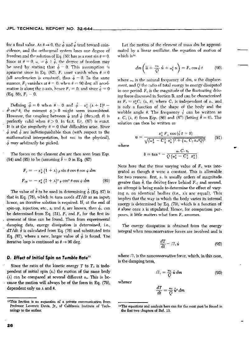
for a final value. As 0 _ 0, the _ and _ tend toward coin- I,et the motion of the element of mass dm be approxi-
cidence, and the ortho_onal system loses one degree of mated by a linear oscillator, the equation of motion of
freedom and the solution of Eq. (50) has as a root sin 0 =: 0. which is '_
Since at 0 = 0, ,,,. = _ + _, the deeree of freedom may
( "_" _, + o,o u) = F,, cos _ t (90)be used by statin-, that _ = 0. This assumption ;s dm Ft +-_-apoarent since in Eq. (82). F, must vani,;h when 0 ----0
(all acceleration is constantS, thus _ = 0. In the same where ..... is the natural frequency of din, it the displace-manner. F.. vanishes at 0 --- 0: when 0 -_ 90 dee. all accel-
ment, and Q the :'atio of total energy to energy dissipatederation is alonq the z-axis, hence F_ = 0; and since 6 = 0 in one period. F,, is the magnitude of the fluctuating driv-
(Eq. 86), F__= 0. ing force discussed in Section B, and can be characterized
as F,, -= s ozC_,(X, 0), where C, is independent of so, andDefining 6=0 when 0=0 and 6=so (h+ 1) 2- is o,_iy a function of the shape of the body and theo
02csC 0, the moment q_> 0 might seem inconsistent, wobble angle 0. The frequency _ can be written as
However, the couplinq between _, and 6 (thro_teh 0) is s.. C., (x, 0) from Eqs. (86) and (87) (letting tJ = 0). Theperfectly valid when 0 > 0. In fa2t, Ee. (87) is exact, solution can then be written asIt is at tile singularity 0 = 0 that di_culties arise. Since
_, and _ are indistinguishable then (with respect to the s o F o cos (,_ t 4- 8)
mathematical interpretation, but not to the physical), u = _/(°'__ Cz so )" + (_o,,C__so/Q) 2 (91)may arbitrarily be picked, where
r
'/'he forces on the element dm are then seen from Eqs. 8 ---:tan -_ - Q (_ _ C_ s_)(84) and (85) to be (assuming _ = 0 in Eq. (87)
Note here that the time varying value of Fo was inte-2 (l +x) sin0cos0cosedmF,-- -s o p grated as though it were a constant. This is allowable
for two reasons: first, s., is usually orders of magnitude
F_, = - s_ (1 + ,_)_p cos -°0 cos q, dm (89) greater than b, the driving force behind Fo; and second,
an attempt is being made to determine the effect of vary-
The value of 0 to be used in determining 6 (Eq. 87) is ing s, on identical bodies (i.e., h's are equal). This
that in Eq. (76), which in turn needs dT/dt as an input; implies that the way in which the body varies its internalhence, an iterative solution is required. If, at the end of energy is determined by Eq. (79), which is a function ofspin-up, injection, etc., s, and 0,, are known, then _,,, can 0 alone once _ is stipulated. Hence, for comparison pur-
be determined from Eq. (51). F, and F_ofor the first in- poses, it little matters what form F,, assumes.. crement of time can be found. Then from experimental
damping data, energy dissipation is determined, i.e., The energy dissipation is obtained from the energy
dT/dt. 0 is calculated from Eq. (76) and substituted into integral when nonconservative forces are involved and is
Eq. (87), where a new, larger value of _ is found. The
iterative loop is continued as 0 _ 90 deg. dTd-F--_* _ (,qg.)
D, Effect of |nitiol Spin on Tumble Rate _ where :7, is the nonconservative force, which, in this c_se,is the damping term,
Since the ratio of the kinetic energy T to To is inde-
pendent of initial spin (so) the motion of the same body _7_ = _o,,t_(x) can be compared at several different so. This is be- -_ dm (93)
cause the motion will always be of the form in Eq. (79), whence
dependent only on X and O. dT _ ,_. h2 dmd-7-
asThis Section is an expansion o_ a private communication from14Professor Leverett Davis, Jr., of California Institute of Tech- The equationsand analysisherecan for the most partbe found in
nology to the author, the firsttwo _haptersof Ref. 10.
26
1965008264-032

JPL TECHNICAL REPORT NO. 32-644
u is calculated from Eq. (91). Since t_':is an oscillating c. When the natural frequency of the system is low,function [sin _ (¢t + 8)], the average value of T over i.e.,so >> o,o,th_'n
one cycle is 8c = P _Oo-
' /dT_ = o,,____,, and 0 (and time) is independent of So.N d--i'/Ar Q <u_-> av dm
If _ passes through a resonant frequency, _ = _
_ so6C_2Fo o,o at some point of the transition, then the energy
)2 (_s,,_)""5_Q dm dissipation will be greater. The magnitude of 0 is(¢o_o-C_ so + also a strong function of %0and Q. In case a, where
_o > > So> > so�Q, then 0_< P. In case b, where Q
(94) is small, and _ooand. so are intermediate, it may beapproximated that #b_" P (C_ < 1). In case e, where
The equation for 0 is then o,ois small and Q is ir,*ermediate, C_ < < 1, and itfollows that 0_ > P. It may be generalized that
do Fo Q
--= " ----(_..S,,y I Explorer I, with its long whip antennae with lowdt 2 I.-x sin 2a -C_ s._)= + natural frequency, fell in case c.
(95)As a rough cut of the time required to tumble, if
, \Three case_ present themselves: _,dT/dt/is assumed constant over the range of interest,then _"
._ - _ dT -1Tmax Train 1 (I_i,)/_
a. If the natural frequency is very high. gid system), At (_ dT/dt N/_, 2 s_ _ dt _A,so that t_o> > So, and the damping is very small,
Q > > !, which implies ,oo> > so�Q, then Eq. (95) where (dT/dt_/-t_ is determined from Eq. (94).reduces to
so E. Discussion
The problem may be reduced to this: Sinee the dynami-where eal relations (Section V-A) and forces on the element
(Section V-B) are known, it remains only to (1) recognizep = C_ F_ those elements of the body which will be affected by the
2 I: _,sin 2_' forces, (2) define the mathematical model to which eachbelongs, and (3) determine the values of the constants to
ar,d the rate of change of O is proportional to be used.
s_ . Hence, the time reqaired to go the same number
of degrees (say from 2 to 75) would be proportional General conclusions are best summed up by clescribingto 1/s o. items to be avoided when designing bodies for spin.
1. Try to make roll inertia greater tha'a the inertia inb. If Q is very small (large damping), so that other axes (e.g., Apollo), in which case the problem
so/Q > .'>o_o> > So, then Eq. (95) becomes vanishes.
, 2 2. If this cannot be accomplished, make the body as0_ = P Q s----2-° rigid as possible, avoiding any liquids, dangling wires,
_,,C _ etc. Make all bulkheads parallel to the roll axis stiff. II
and the time to go between equal values of 0 is 3. If neither 1 nor 2 is possible, keep the design spin
proportional to 1/s _. rate soas smal! as possible within other system constraints.
27
1965008264-033
JPI.. T_'CHNICAL REPORT NO. 32-644
In general, it appears from past results that this phe- rate was decreased by over two orders of magnitude, then
nomenon is not hard to &-sign around. If, by merely one may conclude that internal damping is something oneremoving the whip antennae on an Explorer I, the tumble designs in rather than out of the typical spinning body.
Vl. SU/_MARY AND GENERALCONCLUSIONS
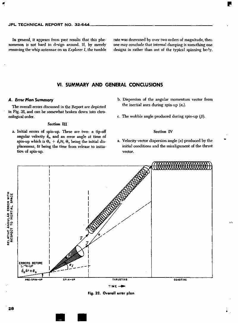
A. Error Plan Summary b. Dispersion of the angular momentum vector from
The overall errors discussed in the Report are depicted the inertial axes during spin-up (a,).in Fig. 39,, and can be somewhat broken down into chro-nological order, c. The wobble angle produced during spkn-up (/3).
Section HI
a. Initial errors of spin-up. These are two: a tip-ott Section IV
angular velotity 0o, and an error angle at time ofspin-up which is Oo + Oo_t, O, being the initial dis- a. Velocity vector dispersion angle (a) produced by the "
placement, 8t being the time from release to initia- initial conditions and the misalignment of the thrusttion of spin-up, vector.
1965008264-034
JPL TECHNICAL REPORT NO. 32-644
b. Velocity vector dispersion magnitude, errors in Sections III and IV are minimized with respectto shape, and the discussion in Section V does not apply;
c. Final wobble angle (fl_). and (2) all error sources, such as initial conditions, thrust
misalignment, etc., should be minimized. Other conc!u-
Seetlon V sions are: (3) during spin-up, both the spin torque andthe spin rate should be as large as possible; (4) when
a. Effects of nonrigidity on wobble angle. This part is thrusting, the number of revolutions through which the
not an error (as in Sections III and IV), however body turns should be as high as possible, i.e., sot_ should
it can affect the spacecraft performance if neglected, be large. As a rule of thumb (noted from the results of- Section IV), if s,,tJ2,r < 3 reyolutions, then little is gained
by spinning; and (5) for coast stability, the body should be
B. General Conclusions as rigid as possible and be spinning at the lowest possiblespin rate. The obvious contradiction between conclusions
The first two conclusions may be stated categorically, 4 and 5 is resolved by despinning after thrusting. Appen-(1) whenever possible, ;t > 0, i.e., the inertia about the dix E contains general equations for despinning by the
spin axis should be as great as possible. If this is true, "yo-yo" method.
1965008264-035

JPL TECHNICAL REPORT NO. 32-644
REFERENCES
1. Leon, H. h, Spin Dynamics of Rocketsand Space Vehicles in Vacuum, Space Tech-nology LaboratoryTR-59-0000-00787, September16, 1959.
2. Goldstein, H., "Classi:al Mechanics," Addison-Wesley, Reading, Massachuseffs,1959.
3. Jahnke-Emde-Losch,"Tables of Higher Functions," McGraw-Hill Book Co. Inc.,New York, N. Y., 1960.
4. Davis, L., Jr., Folfin, J. W., Jr., and Blitzer, L., "Exterior Ballisticsof Rockets,"D. Van Nostrand Co., !nc., Princeton,New Jersey, 1958.
5. Pearcy, T., "Table ._f the Fresnel Integral to Six Decimal Places," CambridgeUniversityPress,1956.
6. Syrett, H. E., and Wilson, M. W, "Computation of Fresnel Integrals to 28 Fig-ures:Approximationto 8 and 20 Figures," Computer ScienceDepartment, Uni-versity.'>fWestern Ontario, London,Ontario.
r
f f -f'7. Rosser,J. B., Theory and Application of e 'z' dx and e-Pv dy e-z*dx
Part I, Methods of Computation, Final Report B2.1 from Allegany BallisticsLab-oratory, OSRD5861.
8. Rosser,J. B., Newton, R. R., and Gross, G. L., "Mathematical Theory of RocketFlight," McGraw-Hill BookCo. Inc.. New York, N. Y., 1947.
9. Pilkington,W. C., Vehicle Motions as Inferred from Radio-Signal-Strength Rec-ords, External Pu_'licationNo. 551, Jet PropulsionLaboratory, Pasadena, Cal-ifornia, September5, 1958.
10. Slate:, J. C. and Frank, N. H., "Mechanics," McGraw-Hill Book Co. Inc., Nev,York, N. Y., 1947.
11. Lass, H., "Vector and TensorAnalysis," McGraw-Hill Book Co. Inc,, New York,N.Y., 1950.
12. Powell,R. B. and Smith,R. L., Dynamics of Spinning Re-entry Bodies, AIAA PaperNo. 64-470, June 1964.
13. Wilson, R. H., Jr., Rotational Magnetodynamics and Steering of Space Vehicles,NASA TN-D566, September1961.
14. Creech, M. D. and Fergin, R. K., "The Yo-Yo De-spinners... New MechanismStopsSpin of RotatingMasses," Product Engineering, p. 597, April 3, 1961.
15. Cornille, H. J., Jr., A Method of Accurately Reducingthe Spin Rate of a RotatingSpacecraft, NASA TN D-1420, October 1962.
16. Fedor, J. V., Theory and Design Curves for a Yo.Yo De.Spin Mechanism forSatellites, NASA TN D-708, August1961.
17. Fedor, J. V., Analytical Theory of the Stretch Yo-Yo for De.Spin of Satellites,NASA TN D-1676, April 1963.
3O
l '
1965008264-036
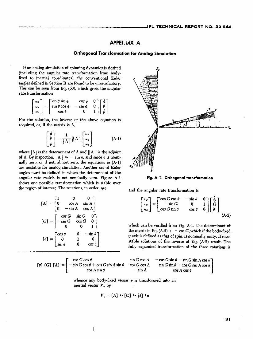
JPL TECHNICAL REPORT NO. 32-644
APPEt.OIX A
Orthogonal Transformation for Analog Simulation
If an analog simulation of spinning dynamics is desired zo(including the angular rate transformation from body- . 1fixed to inertial coordinates), the conventional Euler z /:angles defined in Section II are found to be unsatisfactory. \
"[qaiscan be seen from Eq. (50), which gives the angular _'_/_(_-___rate transformation _5_
_v = | sin 0 cos _ -- sin I/,": L cos 0 0 3 r
For the solution, the inverse of the above equation is " '"'.required, or, ff the matrix is A, ';' •
i' "-.-- ....' ...... Yo
= -_ II Aii ,o,,o_ (A-l)
where IX!isthe determinant of A and II'_ i[is the adiointof A. By inspection, I A [ = - sin 0, and since 0 is nomi-nally zero, or if not, almost zero, the equations in (A-l)are unstable for analog simulation. Another set of Eulerangles must be defined in which the determinant of the xangular rate matrix is not nominally zero. Figure A-1 Fig.A-I. Orthogonal transformationshows one possible transformation which is stable over
the region of interest. The rotations, in order, are and the angular rate transformation is
[! o []o, sin0i][!][A] = cosA si _'v =| -sing 0- sinA cosA] _" LcosC sinO cosO
[" cosG sing 0-] (A-2)
tG]=L-sin0c 7J0 which can be verified from Fig. A-1. The determinant ofthe matrix in Eq. (A-2) is - cos C, which if the body-fixed
rcoOO 0 -Sino01 y-axisis definedas that of spin,is nominally unity. Hence,= 1 stable solutions of the inverse of Eq. (A-l) result. The[o] Lsino 0 coso] fully expanded transformation of the three rotations is
I- cos G cos 0 sin G cos A --cosGsinO+sinGsinAcoSOo1[0] [G] [A] = 1- sin G cos 0 + cos G sin A sin 0 cos G cos A sin G sin 0 + cos C sin A cos JL cos A sin 0 -- sin A cos A cos 0
whence any body-fixed vector ¢ is transformed into aninertial vector Vo by
Vo= [A]-,. [c]-,. [01-,_
1965008264-037

JPL TECHNICAL REPORT NO. 32-6d4
APPENDIX B
Exact Formulation and Numerical Solution
I. NONLINEAR EFFECTS
If nonlinearities are present in the system, Lhe basic and m(t) is given by Eq. (B-l). The torque about the
differential Eq. (41) and subsequent equations cannot be pitch axis is then
explicitly solved. These nonlinearities usually arise out of L, = F _ (p + l - x) (B-3)
more exact formulations of the problem. If the assumption of rh made in Eq. (B-l) is not valid, thenwhatever m(t) is assumed must be pointwise integrated.
a, Variable Mass During Burning. The largest single
cause of inaccuracies in Section IV is the mass decrease Decreases in the roll inertia can be neglected, since to
during burning, which decreases inertia. A good mass a first order the mass thrown out by the motor takes withapproximation assumes a constant thrust, thus constant it angular momentum, keeping the spin rate about the
mass flow rate, roll axis constant at so. Except in cases of very large
(/___) mass decreases during spinning, the variation of I.- canm = mo - yht =mo - t (B-l) probably be neglected (since the mass of propellant being
expelled is usually situated close to the roll axis, thus y
where mo is the total mass at t = 0, and Ise is the rocket contributing only a small part of the total I:. In the case
propellant specific impulse. Inertia changes may then be for Apollo, all changes in inertia, both pitch and roll, arecharacterized. If the rocket motor is considered a poi'_t neglected. However, for Ranger, when _ of its mass is
mass at the end of a thrusted body (see Fig. B-l), then expended during burning, these variations must be takeninto account.the inertia change in the cross axes (pitch-yaw) is the
initial inertia decreased by a changing mass effect asb. ]et Damping. When a body, rigid or not, has a
determined by the parallel axes theorem. In effect, the cross-angular velocity (i.e., _ = o,, +/_v --_ 0) during the"rigid body" mass (M) remains constant, while the rocket expulsion of mass along the z-axis, a damping arises out
motor attached to one end decreases in mass (m). The of the fact that the cross _ causes a "wagging" of the ietpitch inertia (as a function of time) is stream, i.e., a change in the direction of the linear momen-
tum vector. "Hue magnJ.tude of this damping (Ref. 8, p. 21)
I,(t) = Ix + I_ + Mx _ + m (l - x)_ (B-2) is proportional to the rate of mass expulsion, and to thecross-angular rate. The damping occurs because, ff
where Ix = inertia of M (rigid body)about its c.m. increases, the rate of change of the linear momentum
I, = inertia of m (rocket motor)about its c.m. vector of the exhaust gases is greater, and thus causes agreater resistance to the increase in _. If _ is the mass
l = distance between mass centers (can be flow rate, and the distance (l + p - x) from the combined
variable), c.m. to the point of thrust application, the jet damping- term is-corn(l+ p- x)_-.
m
M + m e. Smalt Angle Approximations. The expediency of
letting sin 0 _- 0 and cos 0 ._ 1 in the inertial transfor-
ROCKETMOTOR c.mj _-COMBINEDc.m. mation is obvious from the analysis. From practical_.q considerations, this approximation is usually valid, since
-''_/-_p7 _b-x real systems seldom can tolerate angular disturbances
j -_- _ greater than 5--10 deg without intolerable error buildup.
m o_M¥c._m,M If, however, this approximation cannot be used, the
t.. LPOINT OF THRUST_ solutions of the inertial transformation must be made
APPUCATION RIGIDS ' " with the full Eulerian expansion, resulting in transcen-
Fig. B-1. Schematic of mass variation dental differential equations.
32
!
1965008264-038

JPL TECHNICAL REPORT NO. 32-644
d. Roll Moment. During the burning of some rocket the full inertia tensor must be included in Euler's dy-motors, a roll torque is generated. If this is to be con- namical equations and carried along in the subsequentsidered, the _.- vector in Eq. (41) is no longer constant, analysis (see, for example, Ref. 1 or 12).but must be varied according to the roll acceleration. g. Nonrigid Effects. If the strain on structural mem-
bers and mass deflections are to be considered, the
e. External Forces. Gravity and solar pressure are in- problem incr___es tremendously. Euler's dynamical eqt, a-ertial forces, hence they may be neglected with respect tions must be modified to include cross-products of inertia,to the spinning dynami._s, but must be included in anyvelocity calculation (e.g., Eq. 62). Aerodynamic forces time-varying coe_cients, and c_er nonlinear effects
discussed be|ow. Each effect of nonrigidity must beare only partially inertial since they depend on the angle treated separately, e.g., mass unbalance wiU affect inertia,of attack 8 (sometimes on _), and are independent of ¢ cause cross-products, c.m. shift, etc.; straining of thein a body of revolution. Good discussions of aerodynamic structural members will cause mass unbalance, rotationforces can be found in Refs. 4 and 8.
of the thrust vector, etc.
f. Cross Products of Inertia. It has been assumed in this h. General Nonlinear Effects. These include variationsreport that all cross-products vanish, since the present in thrust -,ector misalignment with time, variation oftechnology is such that the principle axes of the body thrust xsqthtime, etc. Each one of these must be includedand the geometrical axes can be made almost coincidm:t in th._ basic differential equation and be numericallyin bodies of revolution. To consider the crc)ss products, inte_ated.
II. GENERAL FORMULATION
Combining as many of the aforementioned effects as rates _(t) =: _o:(t) + i o,u(t), which, with the solution ofpossible, the basic equation for the body-fixed o, is then _.-= N:(t) [if there is a torque in the z-direction] are
substituted into Eq. (8). The numerical solution of this
_ L(t) (B-4) set of equations will _ve the time functions of the Euler;_+ i_,..(t) {X(t) - rh (l + p - x)_-} ,, I_(t)
angles (6, O, ¢) which define the inertial transformationwhere the time functions of o,..,x, x, l, L, I, and rh (ff not matrix F. The inertial thrust vector is then determined,constant) are to be stipulated. Equation (B-4) is then which, when divided by re(t) and integrated, 'fields thenumerically integrated to determine the cross-angular inertial velocity vector.
33
I
1965008264-039

JPL TECHNICAL REPORT NO. 32-644
III. SPECIFIC EXAMPLES
Ranger is an ideally suited examt_le here, since % of on Fig. B-2. Looking at Fig. B-3, the output of the above
the weight of the original system is expended. Table B-1 problem, it is seen that the K _- - 10,000 in the approxi-gives the parameters used in the problem, mation is close to the true solution on Fig. B-3. However,
the shape of the solutions do not agree too closely. IfTable B-1. Ranger parameters the proper value of K c_uld be assumed, the approximate
solution could suffice for values of ct(t).Thrust f (constant), Ib 5500
Burning time tb, sec 9.6
Payloadmass,Ib 96.0 The Apollo problen',s in Section [v-J were also run onFlowrote/_ (constant},Ib/sec 20.0 the big program Lo illustrate two points. If the mass
Spinrate so,tad/see 30.0 change is ._mall, e a(t) in Figs. 22-25 do m fact closelyLeverarm i_ (/}(variable),in. SeeFig.B-2 approximate t]- _ '.rue solutions in Figs. B-4 through B-7.
PitchinertiaI,, Ib-in.± SeeFig.B-2 The other rea °_ _sthat the brger program allows a lookInertia ratio, h See Fig. S-2
Capsule mass,M. Ib SeeFig.n-2 at V_ vs V_ i a_ re,l vs a_ imaginary. The ApolloThrustmisalignment_'0 ran 0.004 problems were ,hose", because the high spin rate of the
Initialwobbleangle8_,rod 0.001 Ranger capsule made t',.,t, c,, , _o confusing. Figures
t, _t B-8 through B-11 show V_ vs V,, f,_r the I_r'_blcms listedK _ ,_.I-'-_" See Fig. B-2
in Section IV-J. The shape at the cur_,es corroborates the lit
statements made in Section IV-F. Figures B-12 through
This problem is identical to that for Ranger in Section B-15 show a_ real vs a_ imaginary. This is the trace thatIV-J, except there, three points (K = -5000, -10,003, a ray of light located along the body-fixed z-axis would
-20,000) were used to examine the effect of K on ct. make as seen by an observer sitting above the capsule inThese three points are seen to represent the K vs t curve the inertial frame.
34
1965008264-040

, JPL TECHNICAL REPORT NO. 32-644
._W,,'--'X-INERTIA
--X0.69
--068 ]
=- ?=:-o._? I ,_= , .j o¢¢ -- .'< 12 x
\\ ="_ _,oLEVER-
ARM 0.65
I , 6 _40 I 2 3 4 -_ 6 ? 8 9 10
TIME, sac
Fig. B-2. Plots of n_, Iz, K, X and 1_vs tt for Ranger capsule
°°""A I I 'f''I 0.02,...... _---.--..... I /
__,.004412 .....
--/002603 S ---_
, I l I000?94 0 I 2 4 5
, j TIME, sac960
Fig, B-4, a It) vs t for Apollo-shaped capsuleTIME,sac (variable mass), So: 1 rad/sec, @o"" 0.025 rod
Fig. B-3. a (t) vs t for Ranger capsule (variable mass)
35
i
1965008264-041

JPL TECHNICAL REPORT NO. 32-644
0021 6 I I , -_ , .
' /iX i ' 'E ! I / _ i j/ : i\ L j ,
I I 5 '
00,;'23 I / ! ! ' \i ; i I1 i I I ' : \i i i i '
_iT--ii! i_\' !--I>: ooo,o,.___ ....41 ---"___L .L L ! ! _ _,__',______i _ ., , i : I ! i ! ] !ooo_,,_i I 1 , , , \ _-7_-,--1 -- _ .....i b _ -_--k--_---4/ J , I i , it/ _ i ' t ] 4/ ' ' I",X I t oooo7, , ....i .1. l I _ / t '
0004"0 , 2 3 4 5 ' )
_....TIME, sec ._ ] g
Fig. 8-5. ct it) vs t for Apollo-shaped capsule --ooooso -- --(vuriable mass), So= 2 rad/sec, #o= 0.013 rad
I 'I "
0O00020 I 2 _ 4 5
TIME, sac
Fig. 6-7. (_Ill vs t for Apollo-shaped capsule (variablemass), So= 10 rod/sac, 0o = 0.00_ tad
ooo_9 ,", I--X-- - ' F---F--
i ! 10.7587(;
o.oo,o_'--- __------- ":",.7_/O0004g 2 3 4
TIME, sec /
Fig.B-6. a (t1vs t for Apollo-shaped capsule (variable ,7os97mass), So= 5 rad/sec, 0o = 0.005 rad .t=o
-t.31163 1.70597 4.72557 7.74118 10.75870 3.77630
Y,, ft/sec
Fig. B-8, V=vs Vv for Apollo-shclped capsule,So= 1 rad/sec, 0o = 0.025 rod
36
'll mm
1965008264-042

JPL TECHNICAL REPORT NO. 32-644
2 35fOr
.
I i oo2 o-0,42979 0 12637 0.68253 1.23869 I 79483 2._101
_'X' f_/sec
Fig. B-9. V=vs Vv for Apollo-shaped capsule, ooo_9 _o--__--_So= 2 rad/sec, #_ = 0.013 rod ---
-oo,s4,000_9 ooz_o 0.04,00005_,0078e,
ozssso I Fig. B-11. V_vs Vv for Apollo-shaped capsule,
_o = 10 rad/sec, go = 0.003 rad0.23814 l "
- 0.,27,3 1 f "_-_,
__ ) 0057,3 _t=0
C>) _ 00,,.
_ '
-0.007/'3-0.00?73 005373 011520 0.17667 0.25814 0.29660
v,,f,/.c \.Fig. B-10. V, vs V_ for Apollo-shaped capsule, -o_sl44 \
so = 5 rad/sec, go -" 0.005 rod '_
-0,22123 -o2zl_ -o.15144 -o.oes5 -oo.es o.o579_oJz?Ts
Re(oz), rod
Fig. B-12..(i_ a_vs ,_ a_ for Apollo-shaped capsule,so : I rad/sec, #o = 0.025 rad
37
1965008264-043

JPL TECHNICAL REPORT NO. 32-644
t
;_ . _.o ,--o_-ooo620 t _-oooo8_
" '_, _ \\_ L i i i I//lI \\i ,, I -,-T--I--T--_q
_oo..:,., / j-0.06'3C I 1 J 1 -000740
-0 07507 -0.04752 -G 01998 0.00757 0 03512 0 06267 "0 0090:5 -0.00577 -0 00251 0.00075 0 00401 0.0072
Re(aj-)0 rod Re(of), lad
Fig. B-13.._e at vs Jm a_ for Apollo-shaped capsule, Fig. B-14. _/_ea_ vs _,z o_ for Apollo-shaped capsule,So= 2 rad/sec, 8o = 0.013 rad So= 5 rad/sec, 8o = 0.005 rad
0.00343 I ' '
\ ,o.oo_o_/.._, , , ,-\ '-\ ,I
"1o 0.00061 , q * _ *
_ I ' 'A ,-o-- IE I E /IA I I I _ , ,
'-'-o.ooo6o\\ I. I I \ /_" ' ', i_ : -....._L_.,._...,_..,,,p--.___ i___-,,, __
,\, / /_ooo.o_"--L.___.g/ /i-ooo36_ : , , I I
-o.oo361-o.oo2zo-o.ooo8o o.o_o61 o.oozo2o.oo343Re(oz-), rod
Fig. B-15. _.e aj vs ,._mal for Apollo-shaped capsule,=o= 10 rad/sec, 80 -- 0.003 tad
[q
38
l I '
1965008264-044

JPL TECHNICAL REPORT NO. 32-644
APPENDIX C
Thrust Misalignment of Solid Propellane Rockets
of _ = 0.004 rad for effective thrust misalignment from
data gathered from the in-flight measurements of the _ o.loI .....second and third stages of the Scout launch vehicle. All z , t l
E_QW_
four stages of the Scout are solid propellant rockets; _ c r I _ _1tk_.._L.,---'"-J ..... "_:
however, the first stage burns in the atmosphere, making _ Jr/__- _ [I'/'_/_/'_/_
Jl l !v- "T°'°"I[any misalignment data almost impossible to separate -_-oJc _ ,------_----
-_It from the aerodynamic effects, and the fourth stage is _ I• spin-stabilized. The middle two s_.tges are attitude stabil- o
_-0 2(_ized by bang-bang peroxide jets in pitch/yaw/roll.* _ te_ iro 175 leo le_ _o 19_ zoo zo5Vehicle p_tch and yaw motion and rates are telemetered Ft.:GHTTIME,seeand recorded. The slope _f the pitch rate trace when the Fig. C-2. NASAScout$- 127 3rdstage pitch and yawH..,Oz jt:ts are off gives the vehicle acceleration in the thrust misalignment vs timepitch l_lane; ya_' acceleration is obtained in a like man-ner. The vehicle nominal thrust, inertia, mass, etc., is
known as a function of flight time. Hence, the effective component in th_ pitch dLrection and ¢_ being the corn- ithrust misalignment may be determir_ed in either the pone_.t in the vaT direction. The maximum values do notpitch or the yaw plane.** Figures C-1 and C-2 illustrate necess_.rily occur simultane_u:ly.
how the thrust misalignment varied on Scout flight S-127. As seen ira the table, the value for ¢ rarely goes aboveTable C-1 lists m,Yimum thrust misalig.ament in degrees 0.2 deg for sta_e 2 and stage 3. The weight of peroxidefor the second ahd third stages for 12 fligi_ts,_pbeing the loaded on board for these _,o stages is based on a 0.",,5-
*Ro|l deadband is _ -+ tl,./.,deg. miniro_.zing IJ:tcb-tyaw coupling, deg thrust _isalignment for the full duration of secondstage burn, and 0.10-deg thrust misalignment for full
* *This thrust r.isalignrot nt is effective because it is wh_t the vehicleduration for third stage burn. The peroxide supply has
sees from r torquing standpoint, hence it includes the effect of
center-of-mass variations, vehicle bending, etc. It is therefore never been e.d_austed. Thus, from the above numbers,erroneous to speak _f _as onlya solidrocketthrust ].isalignment. it is thought that a value of _ of 0.004 tad (0.2,3 deg_ is
considered conservative for the examples considered hathis Report.
o 4 Table C-1. ScoutthrustmisalignmenteJ
Vehicle Socond _toge Third stage
_- 0. number fp max, de9 _', max, dog _'pmax, dog _, m_-,, dogW
z 5T-6 0.100 0 074 0.026 0.01 !LU
:S $T-9 0.228 0.048 -- --Zo 0 S-113 C,079 0.033 I" "l"--J $-I 14 0.,'_96 0.064 -- --<(
m _ /-_, S.II5 0.1 ;_ 0,136 ,_.048 0.077O. I - _X.,, _ ,'_, 5-I 16 0.090 0.012 _ 0.020
l i'_\_ ''-- _Tpltch $-I 18 0,127 0.027 0.071 0.182n-"_ (Tyo_--'j $-I 19 0.215 0.103 0,065 0.034
I-- O_ _ ",,. ] 5-120 0.134 0.015 0.109"I" 0.455t_85 95 105 115 125 135 145 S-122 0.159 0.029 0.069 0.092
5-127 0,130 0,014 0.062 0.077FLIGHT TIME., sec $-132 0,177 0,077 0.110 0.016
Fig. C-1. NASA ScoutS-127 2nd stagepitchand yaw tSodyoscillations,'_bscured the "mean"rotedata.thrustmisallgnmentvstime tttowthrustpriortoburnout.
39
1965008264-045

JPL TECHNICAL REPORT NO. 32.644
APPENDIX D
ZERO SPIN RATE
In certain applications, a short., high thrust with no Zospin may produce acceptable velocity dispersions (if the A _-V_HSCLE_4velocity, increment is low enough). If saJch is the case, L/idie small angle app-oximatio,i made throughout SectionIV no longer holds. Additionally, if the thrust misalign-ment is assumed constant (as it has been), the motion L_,_T!!when so = 0 is confined to hvo dimensions; either Xo or --'"1//iYo _.ndZo. Referring to Fig. D-l, the curved path is the
actual velocity path followed in the Xo-Zo plane, and the lily!straight line (V) is the resultant velocity vector.
p'j• The angular acceleration of the body is a function ofthe torque, i.e.,
xoo
L IF¢ (D-i) ,,0"=-=N - I. - I= Fig.D-I. Velocitydiagramwhen $o= 0
whereupon, ff the initial tip-off rate is 0o,The integrals in Eq. (D-3) are seen to be modifications
/_= 0o + _ t, and integrating once again, of the Fresnel integral, and ff do= 0,
iF_=. = _ I t iO=Oo+iot+-_,- (D-2) V. \/'-'_-t-'_F._l/_rnz/ S(,_,I:_//___F_/
"_ inertial axes an angle 0o. The velocity components are V.-= \ l!_m", / C _ tthen seen to be
where C and S are defined in Section III-F. The error in
I7, = gF f i sin 0dt the velocity direction is thenmj,
_ gF f' / - IF¢ t= 0otsin IF?, ) a = tan-_ Vz (D-5)-_mj, tsin0otcos_ +cos _t z dt Vv
and V,= g___F_Ff'mJocos0dt and the error in the magnitude is (1 - V-v--D.,!
( "<)_ gF f' cos 0ot cos/F_, t.__ sin 0ot sin-2T_, t' dt Unless tb is very small (< 1 second), V, will probably- -'m-j, zt, be excessive. The velocity is necessarily kept small so
l thrust misalignment is reasonably bounded.(D-3) that thel,r
40-:' ! [
1965008264-046

JPL TECHNICAL REPORT NO. 32-644
APPENDIX E
DESPINNING
After a body has been spun-up and a maneuver has for the rind cord yo-yo are given below, and are taken
occurred, it is often necessary to de-spin. The foUowing from Ref. 14. The deployment of a rigid cord yo-yo is
is a brief listing of some despin de_,Jc_es: depicted in Fig. E-1.
i. Cas jet (hot or :_,Id_. The main drawback in addi- If o,. = initial spin rate, rad/seetion to high weight is the fixed total impulse, whichwill despin only a fixed .number of rpm. That is. ff b :: final spin rate, rad/sec
the jets work perfectly, a 10-rpm error in initial
spin rate will also appear in the final spin rate. 7 = _/,o.
2. Body-fixed magnetic rods in a magnetic, field can m : mass of despin weight (for 1 cord), slugalso stop a rotating body (Ref. 13). However, this
I = inertia of spinning body about spill axis,
method has four main drawbacks: a magnetic field slug-ft=such as the Earth's) must be available, the time
involved to stop the rotating body _ considerable, a =radius of body (to cord attad,ment), ftall spin must be removed, and the use of magneticrods in the body might have some interactions with R :: required length of cord, [tother elements.
T ..... = maximum tension in cord, lb
3. "Yo-yo's" are de_,_ees which decrease spin by re-
leasing weights on cords which umvind due to the t = time to despin, sec
spin, causing large increases in inertia about thethen the length of one cord (there are 2 as shown in
spin-axis. When the cords have unwound, they are
released, taking with them the difference between Fig. E-l) is
the initial and final values of angular momentui.n. R = _ (1- 7) (I + 2ma-')-] v, (E-l)1.1.
Yo-yo's with both rigid and stretch cords have been
investigated extensively in the past five years (Refs. 9, Note that this equation states that for a given R and m,14, 15, 16, 17). For reference, the necessary equations "t = 0/,o0 is constant. Hence, yo-yo's take out a given
(o] (b) (c)
Fig, E-I. Rigid cord "yo-yo" deployment
41
1965008264-047

JPL TECHNICAL REPORT NO. 32-644 ....
1 r(1-7)(i v)-i,.proportion of spin, and a 1% error in initial spin ,ate t = _"Lwill remain a 1% error after despin. However, if 0 = 0, 2m (1 +y) ]
then Eq. (E-l) above beecmes Thus, the faster the body is spinning, the faster the yo-yo
will stap it. The maximum tension in the cord (which is
R,, = F .I -_-2ma-"] '_" assumed massless) isL Om ja1: [ am ]
which states that to despin to 0 rpm, the dimensions of T .... = _ I°(l-.'-'__ma-')_]
the desp_n mechanism (i.e., R., and m) are independent When the stretch yo-yo is used, the effect of errors m
of _o. The time to despin is found by letting R = a,,,..t the body inertia I, initial spin rate o,o, cord length R andin Eq. (E-l) and solving, despin mass m is minimized.
Y
ACKNOWLEDGMENT
The author would like to express his appreciation to W. R. B_mtonand R. Garrett for their invaluable help in setting up the computerroutines necessary for the evaluation of the Fresnel integrals and thenonlinear differential equations.
4:,I
1965008264-048


![Contents · Web view2018-08-09 · Submissions should be emailed in Word format to . ... 24 381 012. C. Average staff [C = A / B] 0.003. 0.003. 0.003. ... allowances relating to](https://static.fdocuments.net/doc/165x107/5ca060a688c993c5178d1719/contents-web-view2018-08-09-submissions-should-be-emailed-in-word-format-to.jpg)


![Quality Report · 2018. 8. 15. · 0.006 -0.003 0.003 -0.001 0.002 Uncertainties (Sigma) 1.990 [pixel] 0.005 [mm] 0.664 [pixel] 0.002 [mm] 0.787 [pixel] 0.002 [mm] 0.000 0.000 0.000](https://static.fdocuments.net/doc/165x107/60fd4e48c8d80d2d9761f76c/quality-report-2018-8-15-0006-0003-0003-0001-0002-uncertainties-sigma.jpg)
