r W Implications of Automotive and Trucking m On-Board ... w r W m Implications of Automotive and...
68
h w r W m Implications of Automotive and Trucking On-Board information Systems for General Aviation Cockpit Weather Systems -- Surabhi Gupta and Pushkin Kachroo Virginia Tech, glacksburg, Virginia = = v National Aeronautics and Space Administration Langley Research Center Hampton, Virginia 23681-2199 Prepared for Langley Research Center under Contract NAG-I-2278 January 2002 https://ntrs.nasa.gov/search.jsp?R=20020038769 2018-06-12T09:46:26+00:00Z
Transcript of r W Implications of Automotive and Trucking m On-Board ... w r W m Implications of Automotive and...
hw
r
W
m
Implications of Automotive and Trucking
On-Board information Systems for General
Aviation Cockpit Weather Systems
-- Surabhi Gupta and Pushkin Kachroo
Virginia Tech, glacksburg, Virginia
= =
v
National Aeronautics and
Space Administration
Langley Research Center
Hampton, Virginia 23681-2199
Prepared for Langley Research Centerunder Contract NAG-I-2278
January 2002
https://ntrs.nasa.gov/search.jsp?R=20020038769 2018-06-12T09:46:26+00:00Z
Acknowledgements
We would like to thank NASA Aviation Safety Program for sponsoring this research (grant number: NAG-1-2278),
and Langley Technical Officer Edward Johnson for his support and guidance during this project.
w
w
=
=
_F
Available from:
NASA Center for AeroSpace Information (CASI)
7121 Standard Drive
Hanover, MD 21076-1320
(301) 621-0390
National Technical Information Service (NTIS)
5285 Port Royal Road
Springfield, VA 22161-2171
(703) 605-6000
w
= .
w
L
r
Contents
Contents ...................................................................................................................................... 2
Abstract ...................................................................................................................................... 4
I Introduction ............................................................................................................................. 4
2 Intelligent Transportation Systems (ITS) and Their Development ............................................ 52.1 Definitions of ITS ............................................................................................................. 5
2.2 Historical Development of ITS Programs in Europe, Japan, and the U.S.A ........................ 6
2.2.1 European Union Initiatives ......................................................................................... 6
2.2.2 Japanese Initiatives ..................................................................................................... 72.2.3 The U.S. Initiatives ..................................................................................................... 8
2.3 Summary of ITS Historical Development .......................................................................... 9
2.4 Technical Issues in Intelligent Transportation Systems Deployment ................................ 12
3 Automobile and Trucking Industry Products .......................................................................... 14
3.1 Interface Technologies .................................................................................................... 14
3.1.1 In-Vehicle Information Systems (IVIS) .................................................................... 14
3.1.2 Display Technology .................................................................................................. 15
3.1.2.1 Liquid Crystal Display (LCD) ............................................................................ 15
3.1.2.2 Organic LED Display ......................................................................................... 15
3.1.2.3 Night-Vision and Head-Up Display Technology ................................................ 16
3.1.3 Speech Recognition Technology ............................................................................... 163.1.4 User Interfaces .......................................................................................................... 17
3.2 Services ........................................................................................................................... 18
3.3 Product and Service Costs ............................................................................................... 18
3.4 Summary of Products Used in Automotive and Trucking Industry and Their Features ..... 19
3.5 Future Developments on Existing Products ..................................................................... 22
4 Enabling Communications Technologies ................................................................................ 244.1 Wireless Data Networks .................................................................................................. 24
4.1.1 Private Mobile Radio Networks ................................................................................ 25
4.1.1.1 Motient .............................................................................................................. 25
4.1.1.2 BellSouth Mobitex Network .............................................................................. 26
4.1.2 Multichannel Multipoint Distribution Service (MMDS) ............................................ 274.1.3 Satellite Data Networks ............................................................................................ 27
4.1.3.1 Teledesic ............................................................................................................ 28
4.1.3.2 Globalstar .......................................................................................................... 29
4.1.3.3 Inmarsat ............................................................................................................. 30
4.1.3.4 Connexion by Boeing TM ..................................................................................... 30
4.1.3.5 Propagation Effects in Mobile Satellite Systems ................................................ 31
4.1.4 Satellite Digital Audio Radio Services (S-DARS) .............................................. 31
4.1.4.1 Companies offering S-DARS ......................................................................... 32
4.1.4.2 Future Planned Capabilities of S-DARS ............................................................. 32
4.1.5 Third Generation Cellular Networks (3G) ................................................................. 334.1.5.1 S-UMTS ............................................................................................................ 35
4.2 Device Technologies for Wireless Connectivity ............................................................... 36
4.2.1 Operating Systems .................................................................................................... 364.2.2 Air Interface / Wireless Modem ................................................................................ 37
-- 2
m
-,..__.
4.2.3 Bluetooth .................................................................................................................. 37
4.3 Challenges to Deployment of Wireless Technologies and Some Solutions ....................... 38
Robust modulation that overcome degradation due to phase noise and coherent de-modulation. 39
5 Market Analysis and Technological Implications for General Aviation .................................. 40
5.1 Oshkosh Survey Analysis ................................................................................................ 40
5.1.1 Current Weather Related Equipment...i ..................................................................... 41
5.1.2 Display Hardware ..................................................................................................... 43
5.1.3 Preferred Features in the Future Equipment .............................................................. 44
5.1.4 Non-Recurring Costs ................................................................................................ 46
5.1.5 Recurring Costs ........................................................................................................ 47
5.1.6 Survey Analysis ........................................................................................................ 48
5.2 GPS Market Acceptance .................................................................................................. 49
5.2.1 Historical Development of GPS ................................................................................ 50
5.2.2 Worldwide GPS Market Projections and Trends in Car Navigation and AviationMarkets ............................................................................................................................. 50
5.2.3 GPS Aviation Market ............................................................................................... 53
5.3 Current General Aviation Market Activities and Products ............................................... 54
5.4 Technological Implications of Automobile and Trucking Information Systems for GeneralAviation ................................................................................................................................ 55
5.4.1 Software Radios ....................................................................................................... 57
6 Conclusions and Recommendations ....................................................................................... 58
Abbreviations ............................................................................................................................ 62
References ................................................................................................................................ 65
Appendix A - Another Weather Information Product: TeleType GPS ....................................... 67
...- ,
--- 3
Abstract
In this study, current characteristics and fi_ture developments of
Intelligent Transportation Systems (ITS) in the automobile and trucking
industry are investigated to identify the possible implications of such
systems for General Aviation (GA) cockpit weather systems. First, ITS
are explained based on tracing their historical development in various
countries. Then, current systems, and the enabling communication
technologies are discussed. Finally, a market analysis for GA isinchlded.
w
w
I Introduction
A broad range of the automobile and trucking industry currently employs on-board, computer-driven
information systems. Key elements that supported penetration of this information system market, such as
data link technologies, information system development, and costs, can have implications for cockpit
weather system penetration in the General Aviation (GA) market.
In this report, current information systems used in the automobile and trucking industry, and the
enabling communication technologies that supported those systems are discussed. The main objective is
to identify the implications of automotive and trucking on-board information systems for general aviation
cockpit weather systems, by investigating similar existing systems. The study was conducted jointly by
the Department of Engineering Management at Old Dominion University and the Department of
Electrical Engineering at Virginia Tech.
Two important focus areas of this study are advanced traveler information systems and commercial
vehicle operations in the automobile and trucking (A/T) industry. The former better defines the systems in
the automobile industry, and the latter in the trucking industry. These systems are referred as A/T in-
vehicle or on-board information systems for the rest of this study. The study examines the current in-
vehicle information systems market in the AfT industry in order to determine these systems' key
characteristics, typical costs, and the future developments. Next, enabling communications technologies,which are selected based on this A/T industry market search and their possible availability for application
in GA, will be discussed, including the challenges in deployment of wireless technologies and possible
solutions. Finally, the results of these discussions are stated in conclusions at the end of this report. The
next chapter examines Intelligent Transportation Systems.
'- 4
w
L
÷w
W
w
w
w
2 Intelligent Transportation Systems (ITS) and Their Development
This section classifies the functional areas in ITS, compares historical development of ITS programs
in Japan, Europe, and the U.S., and identifies technical issues in ITS deployment.
2.1 Definitions of ITS
To provide context, the study of ITS begins with examination of several definitions. IntelligentTransportation Systems (ITS) are in-vehicle information systems that combine information processing,communications, control, and electronics. The purpose of these systems is to improve safety, and decreaseon-route time and money consumption (ref. 1). Telematics is another term that is used to describe thisarea and ITS America (ITSA) provides the following definition: Telematics refers to the consumerproducts, services and supporting systems that deliver information, communications and entertainment toin-vehicle and mobile devices (ref. 1). Based on these definitions, this report employs the followingdifference between ITS and telematics: ITS is the broad infrastructure, products and services, that can bein-vehicle as well as on the road and whose function is to aid transportation. Telematics is specifically thein-vehicle component of ITS and includes non-transportation functions as well (such as entertainment).ITS are discussed first in this chapter and several following chapters. Telematics is mentioned in anumber of following sections, along with a similar term "In-Vehicle Information Systems" (IVIS), which
are the specific on-board information systems that this study focuses on.
According to ITSA, there are five functional areas in ITS (refs. 2 and 3):
Advanced Traffic Management Systems (ATMS) involve the use of sophisticated technologies tomanage the traffic on the transport network. These systems include traffic control systems, freeway ramp
metering, and incident management systems.
Advanced Traveler Information Systems (ATIS) provide information directly to the traveler. Route
guidance, navigation, personal messaging (such as emailing via Internet), location of nearby restaurants,or hotels, etc. are examples of ATIS.
Advanced Vehicle Control Systems involve computer control of the vehicle so that it can travel alongthe highway without human intervention. This area involves collision warning systems and intelligentcruise control.
Commercial Vehicle Operations involve the use of automatic vehicle location systems to permitintelligent management of commercial vehicle fleets. These systems provide more efficient dispatch andscheduling, as well as increased driver safety.
Advanced Public Transportation Systems involve the development of special - purpose publictransport information and control systems. These systems provide passengers with information on thearrival times of buses or trains, allow smart card payment of fares, and improve operational efficiency.
The primary focus areas of this study are ATIS, and commercial vehicle operations in A/T industry.The former better defines the systems in the automobile industry, and the latter in the trucking industry.The next section introduces ITS programs in Europe, Japan, and the United States to provide information
about similarities of these programs and their historical development.
5

w
w
w
L
w
2.2 Historical Development of ITS Programs in Europe, Japan, and the U.S.A.
There are major research and development programs on ITS in the United States, Europe, and Japan(refs. 3 and 4). This section introduces these programs, explains the similarities between them, and
includes a comparative summary in a template format.
2.2.1 European Union Initiatives
The first concept of ITS developed in Europe was known as advanced transport telematics (ATT),and relied on a decentralized or autonomous transportation approach (ref. 4). In the 1980s, vehiclemanufacturers began to realize the limitations imposed by the increasing volume of vehicles in the
European transport network. The limitations were due to urban congestion, increased cost from timedevoted to traveling, accidents, safety, security, environmental pollution and the need to use driving time
more efficiently. Subsequently, manufacturers envisioned the possibility of a new transport system basedon the application and integration of electronics, computers and telecommunications to reduce theselimitations. This resulted in a research program entitled "PROgraMms for a European Traffic with aHighest Efficiency and Unprecedented Safety: PROMETHEUS."
PROMETHEUS began in 1986 with an 8 - year life span. The initial stage of the program (1986 -1987) was a definition phase. There were initially 15 European vehicle manufacturers, but at the laterstages, the program included other research projects sponsored by a number of research institutions. In1988, the launch phase was implemented, with the first project demonstrations and in 1989 the research
component was initiated. The annual funding was US$113 million with two-thirds provided by industryand one-third by national ministries of technology, research and industry. PROMETHEUS led to thedevelopment of several demonstrator programs called Common European Demonstrators (CEDs). Eachwas formed to represent a near prototype stage of research in a particular area. Some of these weresystems such as collision short-range communication, route guidance, fleet management, and traffic andtravel information. The prototypes were usually served as technological demos, showing the practicabilityof taking systems originally developed in other domains such as military and aircraft / aerospacetechnology, and then integrate them into land transport. Members of CEDs programs were vehiclemanufacturers such as Daimler-Benz, Ford, Volvo, BMW, Fiat, Renault, Opel, and industrial and researchestablishments such as GEC-Marconi, IBM, Nokia, Husat, Motorola, Philips, Bosch, and Lucas.
In 1988, a parallel program entitled DRIVE (Dedicated Road Infrastructure for Vehicle Safety inEurope) was adopted by the European Union as an R&D program in transport telematics and informatics.The objectives were the improvement of road safety, maximization of transport efficiency, and
contribution to environmental quality.
The technologies to implement ITS in Europe were varied and developed by different organizations.The European Union Commission determined the major players in ITS to create a public - privateorganization in which participants could work together to make ITS a reality. Therefore, in 1991, theEuropean Road Transport Telematic Implementation Coordination Organization (ERTICO) was formed.ERTICO conducts strategic planning for ITS implementation, analyzes needs and market of ITS, initiates
and participates implementation projects.
PROMETHEUS, and DRIVE were concluded in 1994. However, other programs such as the 4th
FRAMEWORK are presently in progress (based on 1997 data). There are also a number of national
programs initiated by individual state governments. All of these programs execute systems integration,
-- 6
Lw
--=
2.2. 2 Japanese Initiatives
In the 1970s, Japan identified that traffic problems such as congestion and increased road deaths were
occurring due to the fast industrial growth and rapid development of cities (ref. 4). During the middle1970s, Japan worked on improving highways and traffic control systems; and in the 1980s, the JapaneseITS initiative was officially started. National agencies, universities, research institutes, and private
companies worked on projects such as:• Advanced Mobile Traffic Information and Communication Systems (AMTICS),
• Road- Automobile Communication Systems (RACS),
• Vehicle Information and Communication System (VICS),
• Super Smart Vehicle System (SSVS).
The following paragraphs describe these programs:
AMTICS is sponsored by the National Police Agency and supported by the Ministry of Post andTelecommunications. There are approximately 60 private companies participating in the project throughthe Japan Traffic Management Technology Association. AMTICS is designed for route guidance andinformation in urban areas and employs an in-vehicle navigation system that uses teleterminals, which issimilar in operation to cellular radios, for communication between the navigation system and trafficcontrol center. The project was launched in 1987, and pilot tests were carried out in Tokyo in 1988 andlater in 1990. The system is capable of displaying on screen all traffic information collected at trafficcontrol and surveillance centers managed by the police in 74 cities. It displays the vehicle location, route
guidance and information on traffic congestion, road works, and parking, location of major facilities, andemergency information of weather conditions.
RACS is a joint program involving the Public Works Research Institute of the Ministry ofConstruction and 25 private companies. It is coordinated by the National Police and the Ministry ofConstruction. The program was funded with 2 billion Yen and tests were started in 1987 and ended in1989. The system developed from this program has three major subsystems:
• Navigation/route guidance,• Traffic information providing congestion, accident and parking spaces information based on roadside
beacon signals,
• Individual communication system including vehicle identification, monitoring of vehicle location andcommunication data such as phones and faxes.
VICS started in 1991 with more than 200 private sector companies involved. The objective was
reaching better integration of the functions of AMTICS and RACS. Both AMTICS and RACS wereaiming to provide traffic information to the driver, and the main difference was the technical approachused in providing the telecommunication link. The strategic plan of the VICS requires the National PoliceAgency, Ministry of Construction and Ministry of Post and Telecommunications to work together inorder to reach the objective of the program. The program aims to inform the driver about road trafficconditions through the use of the radio communication medium. This requires the National Police Agencyto expand the traffic control centers and analyze the traffic within the network, and the Ministry ofConstruction to operate a system of roadside communication. The two government agencies operate
parallel systems for supplying data to vehicles by a wide area broadcast system (such as FM sideband). Acentral information collection center receives the information, and interprets and displays it at specific
locations on the roads and by FM radio. In June 1993, a demo of the system began in Tokyo, and in
November 1993, 500 people had taken part in the demo, which used 45 vehicles. VICS has set standardson the future use of mobile communications in Japan covering digital cellular radio, and FM sub-carrier
broadcasting.
w
w
w
w
w
SSVS was started in 1990 to promote the R&D of ITS technologies for the next 20 - 30 years. Theprogram was particularly interested in highway safety, and addressed analysis of the characteristics of in-vehicle systems based on technological capabilities, human factors, user requirements, technical, social
and economical issues about the development and implementation of ITS, and policies concerning R&D.Objectives of these systems included allowing the driver to monitor driving conditions and receivebroadcast data, and providing emergency alerts to the .driver. Six areas under this program were:
• Intelligent intersection,
• Intelligent physical transportation,
• Intelligent environment recognition,• Active driver assistance,• Ultraminicar,
• Cooperative driving systems.
Another program, Universal Traffic Management System (UTMS), was initiated by the Japanesecentral government in 1971. The objectives were similar, including development of new traffic controlsystems with information systems, route guidance, public transport systems and pollution monitoring and
advisory systems.
Commercialization of ITS has started early in Japan, and Japan was first to offer navigation systems
as a part of in-car options. According to 1997 data (ref. 4), 12,000 vehicles per month were sold equippedwith navigation systems at approximately US$3000 per unit. The Japanese market for the navigationsystem was one-half million units plus 10,000 split between the U.S. and Europe. In the U.S. market, themajority of these units were installed in commercial vehicles and rental cars.
2.2.3 The U.S. Initiatives
A 1986 traffic study of 29 major U.S. cities estimated that $24 billion a year was lost in those citiesbecause of traffic congestion (ref. 4). In the U.S, more than 41,000 fatalities occur in crashes per year (ref.5), and 5 million people are injured at a total cost of $70 billion (ref, 4). Driver error is the primary causein 90% of these accidents, involving passenger vehicles, trucks, and buses (ref. 5). To improve thissituation, in 199l, the U.S. launched a program initiative entitled Intelligent Vehicle - Highway Systems(IVHS) with an initial budget of $660 million, and establishment of IVHS America (ref. 4).
IVHS America was a Federal Advisory Committee, including various levels of government, privatesector, academic institutions, and transport organizations. The main role of IVHS America was to identifythe most appropriate technologies and strategies for the future development of IVHS (During late 1994,the IVHS board changed its name to Intelligent Transportation Society of America (ITSA)). The ITSprogram is a federally funded R&D program with a greater proportion of the funding coming from the
private sector. It was seen as one of the outcomes of the U.S. Congressional Act passed in December1991 (the Intermodal Surface Transportation Efficiency Act (ISTEA)). This act allowed for the allocationof $660 million, from 1992 to 1997, to relieve congestion and improve safety on the road. The objectivesof the ITS program are to use innovation and technology to fulfill national transportation goals of safetyand efficiency, and to meet the transportation needs of the future. There are six areas of interest identifiedin the strategic plan (ref. 4):
• Advanced travel and traffic management systems,
• Electronic payment systems,
• Emergency management systems,
• Advanced vehicle safety systems,
• Commercial vehicle operations, and• Advanced public transportation systems.
w
The program is administered through the federal Department of Transportation (DOT), but much ofits definition, direction and review are provided by ITSA. ITSA fulfils a public / private partnership roleby giving memberships to private sector companies (50% of all members), and academia, government andassociations (the other 50%) (ref. 1). It helps its members to participate in on-going research, planning,
standards development, and marketing of ITS programs, products, and services. It helps standardsdevelopment on settings, telecommunications, safety, legal and institutional issues. It fosters internationalcooperation, as it is in touch with sister associations in Europe, Asia, Canada, and Australia.
In 1998, the Intelligent Vehicle Initiative (IVI) became a segment of the DOT ITS program (ref. 6).Its focal points are investigating the safety impact of combining multiple systems such as route guidanceand navigation, adaptive cruise control, cellular phones, and in-vehicle computers, and facilitating thedevelopment of driver assistance safety products. IVI systems are primarily developed by the privatesector. The U.S. DOT works cooperatively with industry to define performance specifications.
Development and usage of ITS in the U.S. are growing dramatically. The U.S. TransportationSecretary proposed the following IVI goals in July 19, 2000, asking industry to work with them (ref. 7):
10% of the new light vehicles sold by 2010, and 25% of new commercial vehicles sold by 2010 should be
equipped with one or more IVI systems. The national goal is reducing the crash fatalities by 20% over thenext 10 years. According to a new study published by Telematics Research Group, in-vehicle informationsystems is in the infancy stage and is on the start of an explosive growth cycle in the U.S. While only 5%
of new cars sold include these systems today, by 2006 33% of new cars sold will have them, exceedingthe expectations (ref. 8). Based on another study, the world market for personal vehicles will rise from thecurrent level of $3 billion to almost $13 billion by 2006, with recurring annual service revenue accounting
for over $4 billion of the $13 billion total (ref. 9). According to new analysis by Frost & Sullivan, NorthAmerican Automotive Telematics Market, the total market rose from $60 million in 1999 to $380 million
in 2000. Double-digit growth could bring this market to $7 billion in 2007 (ref. 10).
2.3 Summary of ITS Historical Development
Table 1 includes a comparative summary of historical development of ITS programs in Europe,Japan, and U.S.A., based on the discussions so far. Japan is the first country that officially started workingon ITS projects in 1971. The European Union follows Japan by starting formal research in 1986, andstudies in the U.S. are relatively new, starting in 1991. In all countries, ITS programs were launched as aresult of traffic problems such as urban congestion, increased cost from time devoted to traveling,accidents, rising road deaths, safety, security, and environmental pollution. Driver errors are one of theprimary causes of accidents, and new on-board transportation systems including integration of electronics,computers and telecommunications are expected to reduce these problems. Start dates of these programsare not close. The reason for that could be due to different traffic needs in these countries at differenttimes.
Another similarity of these programs is the cooperation between the public and private sectors. Thepublic sector usually initiates, supports, and leads the ITS studies while private sector contributes to the
funding, R&D projects, and applications. Objectives of these programs are also similar: Providing on-board route guidance and navigation, fleet management, traffic and travel information (such as roadworks, parking, location of major facilities, emergency information of weather conditions, pollutionmonitoring and advisory systems) through various communication systems (such as cellular phones, andin-vehicle computers), and facilitating the development of driver assistance safety products.
w
9
m
The use of ITS is rising dramatically in the countries mentioned above, while an increasing number ofusers prefer vehicles equipped with on-board information systems. According to a 1998 study, usage ofthese systems in Japan, Europe, and Australia has been greatly accelerated through mutual cooperation of
the public and private sectors.
This section has provided general information on ITS in different countries, including historicaldevelopments and similarities between them in terms of reasons to start these studies and theirapplications. The rest of this report focuses primarily on ITS in the United States, beginning with the nextsection that briefly discusses technical issues in ITS deployment.
_ I
w
L
10
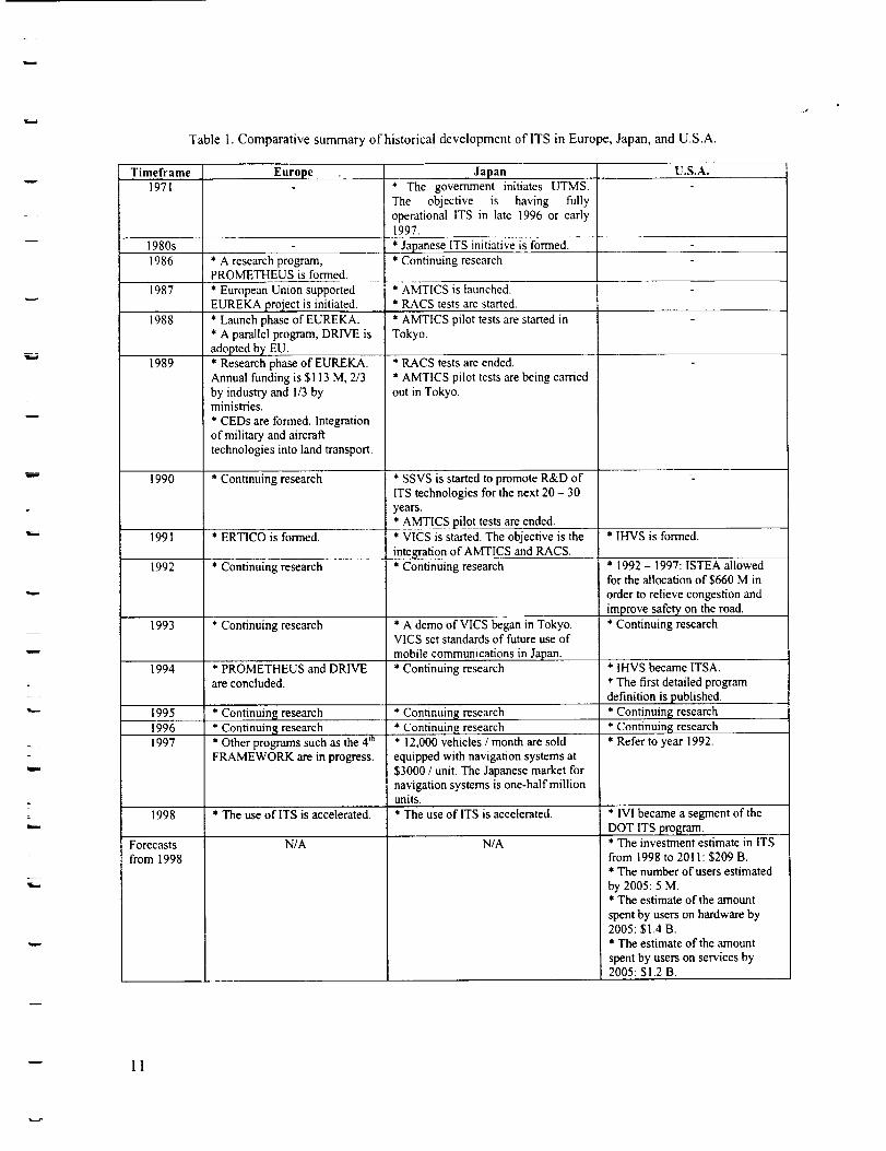
Table 1. Comparative summary of historical development of ITS in Europe, Japan, and U.S.A.
w
I
i •
Timeframe1971
Europe
1980s
1986 * A research program,PROMETHEUSisformed.
1987
1988
1989
1990
1991
1992
1993
1994
1995
1996
1997
Forecasts
from 1998
* European Union supported
EUREKA project is initiated.
* Launch phase of EUREKA.
* A parallel program, DRIVE is
adop ted bY EU.* Research phase of EUREKA.
Annual funding is $113 M, 2/3by industry and 1/3 byministries.
* CEDs are formed. Integration
of military and aircraft
technologies into land transport.
* Continuing research
* ERTiCo is formed.
* Continuing research
* Continuing research
* PROMETHEUS and DRIVE
are concluded.
* Continuing research
* Continuing research
* Other programs such as the 4 m
FRAMEWORK are in progress.
1998 * The use of ITS is accelerated.
N/A
Japan* The government initiates UTMS.The objective is having fullyoperational ITS in late 1996 or early1997.
* Japanese ITS initiative is formed.
* Continuing research
* AMTICS is launched.* RACS tests are started.
* AMTICS pilot tests are started in
Tokyo.
* RACS tests are ended.
* AMTICS pilot tests are being carried
out in Tokyo.
* SSVS is started to promote R&D ofITS technologies for the next 20 - 30
years.
* AMTICS pilot tests are ended.
* VICS is started. The objective is the
integration of AMTICS and RACS.
* Continuing research
* A demo of VICS began in Tokyo.VICS set standards of future use of
mobile communications in Japan.
* Continuing research
* Continuing research
* Continuing research* 12,000 vehicles / month are sold
equipped with navigation systems at
$3000 / unit. The Japanese market fornavigation systems is one-half millionunits.
* The use of ITS is accelerated.
N/A
U.S.A.
* IHVS is formed.
* 1992 - 1997: ISTEA allowed
for the allocation of $660 M in
order to relieve congestion and
improve safety on the road.
* Continuing research
* IHVS became ITSA.
* The first detailed program
definition is published.
* Continuing research
* Continuing research* Refer to year 1992.
* IVI became a segment of the
DOT ITS l_ro_arn.* The investment estimate in ITS
from 1998 to 2011:$209 B.
* The number of users estimated
by 2005:5 M.* The estimate of the amount
spent by users on hardware by2005:$I,4 B.* The estimate of the amount
spent by users on services by2005:$1.2 B.
-- 11
w
L
2.4 Technical Issues in Intelligent Transportation Systems Deployment
A key goal for organizations such as Intelligent Transportation Society of America (ITSA) is thedevelopment of nationally compatible systems that will improve inter-city travel and cross-country goodsmovement while maintaining compatibility and service standards. For example, the program's nationalarchitecture and technical standards define the ITS elements and the way they will work together, and
they are a prerequisite to a large-scale, integrated system deployment.
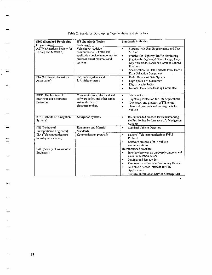
There are constructive results of architecture development. The definition of an architecture leads todevelopment of system interface standards and protocols, and reduces risk to those responsible forproviding ITS infrastructure or investing in the development of ITS products and services. For example,the development of architecture will help resolve issues such as whether optimal routings are calculatedby in-vehicle computers using information transmitted to the vehicle or calculated at traffic managementcenters and then transmitted to vehicles. This single issue has major implications on the costs of in-vehicle equipment (and, therefore, affordability), the costs of providing and maintaining publicinfrastructure, and which communications technologies can be accommodated. A summary of the variousStandards Developing Organizations (SDO) that are concerned with developing ITS standards for mobile
communication applications is presented in Table 2 (ref. 11).
On the other hand, the level of federal involvement in this standardization process is also a topic ofdiscussion. The main issue is that while a large-scale federal deployment (standardization) program would
be necessary to achieve widespread deployment, this would have the drawback that it would limit localflexibility and would increase the cost of regulation and compliance.
The next chapter discusses the current ITS products and technologies that are employed in the marketplace.
w 12
w
Table 2. Standards Developing Organizations and Activities
w
i
Lm
SDO (Standard DevelopingOrganization)
ASTM (American Society forTesting and Materials)
EIA (Electronics IndustriesAssociation)
IEEE (The Institute ofElectrical and Electronics
Engineers)
ION (Institute of Navigation
Systems)
ITE (Institute ofTransportation Engineers)
TIA (Telecommunications
Industry Association)
SAE (Society of Automotive
Engineers)
ITS Standards Topics Standards ActivitiesAddressedVehicles-to-roadside
communications, traffic and
application device intercor/nection
protocol, smart materials and
systems
R-3, audio systems andR-4, video systems
Communications, electrical and
software safety and other topicswithin the field of
electrotechnology
Navigation systems
Equipment and MaterialStandards
Communication protocols
• Systems with User Requirements and TestMethod
• Practice for Highway Traffic Monitoring
• Practice for Dedicated, Short Range, Two-
way Vehicle-to-Roadside Communications
Equipment
• Specification for Data Formats from Traffic
Data Collection Equipment
• Radio Broadcast Data System
• High Speed FM Subcarrier
• Digital Audio Radio
• National Data Broadcasting Committee
• Vehicle Radar
• Lightning Protection for ITS Applications
• Dictionary and glossary of ITS terms
• Standard protocols and message sets forvehicle
Recommended practice for Benchmarkingthe Positioning Performance of a Navigation
Systems• Standard Vehicle Detectors
• National Tele-communications IVHS
Protocol
• Software protocols for in-vehiclecommunications
Recommended practices:
• Interface between an on-board computer anda communication device
• Navigation Message Set
• On-board Land Vehicle Positioning Device
• In-Vehicle Sensor Interface for ITS
Applications
• Traveler Information Service Messase List
w
-- 13
w
m
L
3 Automobile and Trucking Industry Products
A broad range of the automobile and trucking (A/T) industry currently employs ITS. Examination ofthese systems may result in identification of certain technologies and applications that can be used in
General Aviation (GA). For this reason, this chapter and chapter 4 introduce current products andtechnologies in the A/T industry. As a starting point, chapter 3 focuses on ITS in the A/T industry, inorder to identify product and market parallels that provide insight on acceptance of cockpit informationsystems by the GA market. Chapter 4 examines the enabling technologies behind these products.
The information in this chapter was developed from a literature search and user interviews. Thechapter subsections include interface technologies in ITS products in the A/I" industry, various productservices, typical costs, lists of current products and their features, and future developments.
3.1 Interface Technologies
The device interface conveys the information to the user through a number of communicationmediums such as voice, text, visual and audio cues, and graphics. The primary concern is with theportrayal of the information and the method of interaction with the user. This section starts with generalinformation on In-Vehicle Information Systems (IVIS). Then, selected display technologies such asLiquid Crystal Displays (LCD), organic LED (Light Emitting Diode) displays, and night-vision and head-up displays (HUD) are described. After that, based on the information provided, user interfaces are
discussed, and finally product services are examined in brief.
3.1.1 In-Vehicle Information Systems (IVIS)
A fundamental design choice for an in-vehicle information system is whether to locate the computingin the car or in a remote server. In the remote server case, communication with the car occurs only whilethe remote server receives information from other sources, and processes the request based on this and theinformation in its database. In this case, updating the map database, upgrading software or adding newservices does not require changes in the vehicle.
Navigation and route guidance systems are the most common in-vehicle information systems in usetoday. The information presented by most navigation systems includes turn-by-turn directions, dynamicroute calculation based on current location, and turn restrictions and speed limits. GPS signals arecombined with map information stored on CD-ROM to display the position and direction of the vehicle.Most navigation systems also include an electronic gyro-sensor and a speed sensor that enable it todisplay the present vehicle position even in locations where GPS signals may be blocked. The user caninstruct the system to calculate the route based on the following criteria: shortest route, maximizefreeways, minimize freeways, minimize toll roads.
Current IVIS (In-Vehicle Information Systems will be referred to as on-board information systems, or
briefly IVIS for the rest of this report) products do not utilize a large amount of real time data except forlocation, but this is rapidly changing. For fixed services or services that are specific to a particular area,static information databases can be used, which inform the traveler of key locations of interest such asfood, lodging, service and gas stations. Bandwidth suffers when the receiver is in motion, limiting theamount of data deliverable to a moving car. One concept is that when filling up with fuel at a gas stationor convenience store, the vehicle could also fill up with information using a short-range wireless protocol.
14
w
w
w
3.1.2 Display Technology
One of the functions of In-Vehicle Information Systems (IVIS) (see section 3.1.3) is to manage andfuse all driving-related information from a variety of sources. For example, IVIS integrate informationfrom roadway signs, traffic conditions, and other sources for presentation to the driver. Information filter
functions assure that the only messages displayed are those that are important to the driver and whichapply. Display functions optimize the presentation of the message to ambient conditions, driverpreferences, the number of simultaneous messages, the urgency of the current message (prioritization),and signal timing, i.e. when the message will be activated and will be deactivated. The selection ofdisplay modality (i.e. audio or visual) and type of display (e.g. head up), as well as design of displayformats are issues that are faced by designers of IVIS.
The latest dash mounted displays in luxury cars have multi-function displays that integrate commoncontrols, vehicle diagnostics and digitized maps for navigation. Most communication and informationdevices make use of monochromatic or color displays to display a variety of texts, symbols and graphics.Developments in technology have resulted in displays becoming thinner with better resolution and less
power consumption.
3.1.2.1 Liquid Crystal Display (LCD)
LCD is the foremost display technology in use today and has increased from VGA resolution(640x480) and SVGA resolution (800x600) to XGA resolution (1024x768). LCDs available today havevisual quality as good as that of a CRT (cathode ray tube). The original LCDs were based on SuperTwisted Nematic (STN) technology, which progressed into dual-scan STN (DSTN). DSTN displaysdivide the screen in half, with each half being scanned simultaneously, thereby doubling the number oflines that are refreshed per second and creating an image that comes closer to the quality seen on CRTs.More refined versions of DSTN, such as High Performance Addressing (HPA), are making the DSTN
displays better. The current state-of-the-art in display technology is the active matrix Thin Film Transistor(TFT) technology. Active matrix LCDs address each pixel on the display individually and provide ahigher refresh rate than DSTN, creating clearer images with higher contrast and more vibrant colors. TFTdisplays have an active-matrix backplane that puts a thin-film transistor behind every pixel.
The latest Super XGA + TFT screens support extra high resolutions of up to 1400x1050 pixels.While dual scan displays are still being used quite a lot, the recent closing of the price differentialbetween DSTN and TFT displays indicates that it is likely that DSTN will be used on fewer systems inthe coming years.
The greatest drawback of LCDs is that they are expensive and, for example, may account for as muchas a third of the cost of a laptop. The failure to reduce the price of portables as dramatically as the price ofpersonal computers has been due largely to the inability to decrease the cost of the display-screen. The
complex and difficult manufacturing process of the LCDs is the reason for this, especially when it comesto high-end versions used in color displays.
3.1.2.2 Organic LED Display
A radically different technology, called organic light-emitting diodes, is a possible alternative toLCDs. This device resulted from the discovery that, when charged by electrodes, certain organic materialsemit their own light, and have the ability to exhibit ultrabright colors and process high-clarity videoimages. The ability to display video comes from the property that they can be switched on and off
-- 15
w
w
w
quickly, which is crucial for video, where images are updated 50 or 60 times a second and get blurred ifthe screen cannot keep up.
One of the drawbacks of LCD technology has been the inability to view the display at all angles, andthis remains a problem today. Organic LEDs may address this problem since they look equally bright
from all angles. The most significant advantage over LCDs is that they have much simpler and thuscheaper manufacturing process. Their structure in principal is an electrode, some organic material, andanother electrode. When a voltage is applied, light is produced without any need for backlight, diffuser orpolarizer as in the LCDs. They also have far lower power consumption than LCDs since LCDs needbacklights to be visible in daylight and this is a major drain on the portable's batteries. The organic LEDsare beginning to appear in some of the new released models of cellular phones and will eventually have asignificant market share in the coming years.
3.1.2.3 Night-Vision and Head-Up Display Technology
With the advent of in-vehicle information systems, the driver has a multitude of information being
presented, usually on a LCD panel mounted in the center console. This requires the driver to momentarilyglance away from the road to scan the information presented. For example, with in-vehicle navigationsystems, the driver may be required to scan route guidance information, such as the distance to thedestination. As a solution to this, Head-Up Displays (HUD) are being developed that display the vehiclecontrols as well as navigation information in order that the driver does not avert his eyes from the road.
In automobiles, HUD information is projected onto the windshield through a projection device calleda Fresnel Lens (Stokes). Typically, the HUD information is optically conveyed to appear to be virtually1.5 to 6 meters away from the driver. Thus, if a car were equipped with a HUD that displayed the vehicle
speed on the windshield, it would appear as if the speed were floating in space 1.5 to 6 meters outside thefront windshield. Such exotic technology that was once only in the realm of fighter aircraft can now bestandard equipment in the high-end Pontiac models. These cars contain the EyeCue system, whichdisplays a digital representation of vehicle speed, the current radio station, and the status of thedirectionals in a HUD. In addition, some Cadillac models are equipped with a HUD-based night visionsystem. With this system, an infrared picture of the road ahead is presented on the windshield to aid innight driving.
The minimal amount of information should be presented on a HUD so as not to obscure the view outof the windshield. Due to the unproven cognitive issues and factors related to the interference with thedriver's view of the external environment associated with the use of HUDs, the deployment of HUDs in
automotive information systems has been negligible and the technology is still in the trial stage.
3.1.3 Speech Recognition Technology
Speech recognition is the ability for a device to recognize individual words or phrases from humanspeech. These words can be used to command the operation of a system (computer menus, voice-activated controls or direct input of speech into an application). This technology is becoming veryimportant in the vehicular industry, because of its ability to reduce distraction, and increase driver safety.
For example, speech recognition technology allows motorists to instruct a navigation system where theywant to go and then listen to the system tell them turn-by-turn directions using actual street names andnamed places. Applications are being developed that control the vehicle's electronic systems such astemperature, lights, door lock and sound through voice commands. On-board speech recognition hasalready been deployed in high-end model of Jaguar, General Motors and Daimler-Chrysler to access
radios, CD players and navigation systems.
_" 16
=
Lw
w
Important for the satisfactory operation of a good speech recognition system is the noise suppression
and noise cancellation techniques that prevent the ambient noise from blanketing the actual speech.Vehicles, unlike desktop PCs, are subjected to a wide variety of noises that can confuse software-basedspeech recognizers. There are numerous noise sources including the road, wind, defroster, fan, radio,windshield wipers and backseat occupants. Another factor that affects the sensitive speech processinghardware is the electrical noise introduced by other car electronic systems that share the power supplywith on-board speech recognizers, for example, air-conditioners. Compounding the problem is that in-vehicle speech recognition is often done by remote servers over cellular links. Speech recognition over acellular link is technically challenging as the system deals with more than just the noise generated by thevehicle.
A technique used to increase the accuracy of the speech recognition is for the processor to map theparticular signal characteristics or frequency spectrum of the user's voice through a set of training data.This information can then be used to extract the signal from surrounding noise by selectively cancelingout all other interference except the known signals of interest. However, even though there are noisecancellation techniques available, these mostly work for steady-state noise and random and fluctuatingnoise sources such as children in the back seat, windows opening and closing, and mechanical noises inthe cabin cause problems. Automakers are concerned about even the subtlest lack of accuracy because itcould place greater "cognitive load" on the driver, who theoretically should be free to concentrate ontraffic and driving conditions (ref. 12).
Despite these problems, speech recognition is being extensively promoted because it is considered asan essential component to the successful implementation of safe and practical in-vehicle information andcommunication systems.
3.1.4 User Interfaces
Telematics (see section 2.1) developers still debate the interface for in-vehicle information systems(voice, screen, or some combination plus ways to decrease the 'cognitive load'). One method ofdetermining the attention required of a particular device interaction is to list the steps that need to beperformed to get the desired result. Generally, this consists of the time it takes to enter the input, and thetime to mentally process the auditory or visual information, by assigning a 'visual task time' to the wholeoperation.
Enhanced user interfaces can be developed that 'learn' the frequent functions accessed by the user orthe pattern of use, and subsequently re-configure the display to make those functions most easilyaccessible or visible to the user.
Since the costs of having a large LCD panel in the dashboard can be prohibitive for most users,several automakers are offering a system that can work with existing hardware. For example, SiemensAutomotive plans to borrow a display, storage, and processing power, from a Palm Pilot or otherhandheld device that would slip into a docking cradle. That would not only hold down costs but alsoprovide in-vehicle access to electronic address books, phone lists and schedules. It would also offer moreseamless connection between the car and the rest of the driver's life since whatever was downloaded in
the vehicle could be carried outside, and vice versa. When the car is started, the following four choices
appear on the Palm's screen: Navigation, Traffic, News, and Messages.
17
w
L
w
3.2 Services
Various in-vehicle information products offer advanced features and value added services such as textmessaging, concierge, traveler information, weather information, vehicle operation reports, maintenancealerts/reminders and rideshare information. The latest in-vehicle "driver information systems" devices
such as in-dash units or pen-based handhelds are equipped with on-board computing systems, routing andreporting software, and Global Positioning Systems (GPS). The menu of advanced travel information
services slated for future in-vehicle information systems will include real-time congestion reports, travelincidents by location, road maintenance sites, parking availability, transit bus and train schedules androutes, schedule of public events, and electronic yellow pages information. Some of these services such astraffic information will be available from state or federal transportation authorities through variousbroadcast or two way microwave or RF links and also privately through the internet or private serviceproviders for a subscription.
3.3 Product and Service Costs
In-Vehicle Information System (IVIS) costs are generally divided into device and installation costs,and service fees. These are also referred as non-recurring and recurring costs respectively. In this section,typical costs are discussed for automotive and trucking Industries separately.
Based on an interview with a carrier company that has a fleet of trucks, an information system
provider charges $1,700 as the non-recurdng cost for its in-vehicle system that provides servicesparticularly for the trucking industry. It is a cellular-based on-board system with two-way text and voicecommunication, and a separate GPS. It also has a separate display, and it can be integrated with PC-basedsystems if required. This system has other services such as emergency signal to the dispatcher. Theinformation system provider charges 50 cents per message (the recurring cost), and this costs the carriercompany approximately $55 per truck per month. Since this information was not obtained by publiclyaccessible sources, company names are kept confidential. Based on the literature search on informationsystem costs in the trucking industry, these are typical costs for a typical In-Vehicle Information System.
System costs in the automotive industry differs from the costs in the trucking industry. This is oftendue to the fact that the information system costs are included in the total price of the car. Therefore, there
are often no non-recurdng costs, but the recurring costs still exist. For example, in 2001 models ofMercedes-Benz, there is a system called COMAND, integrated into the front panel. Communication isthrough text messages, and there is a push-button system that allows the driver to access her/his web pageas well. The web page should be previously personalized by the driver within the Mercedes-Benz USAweb site at www.mbusa.com. These web-based information services are provided by another company:CNN Interactive. It may contain information on stocks, weather, sports, news topics, etc., according to thedriver's personal interests. This service does not require a non-recurdng cost additional to the price of the
car, but an annual recurring cost is required, which is $125 plus airtime.
While the previous paragraph is an example of IVIS, integrated into the front panel in automobiles,there are also a number of portable systems such as the Scout Electromedia - Modo. This is a satellitebased, portable system, including information about restaurants, shopping, hotels, and other attractions inthree major cities: New York, Los Angeles, and San Francisco. This information is updated daily withoutany charge. There are no recurring costs for this system, while the non-recurdng cost is $99. Similarinformation about other cities will be added to the system in the near future.
18
w
w
w
r=
This section included typical costs of IVIS in automotive and trucking Industries. The followingsections summarize information system products currently in use in these industries and their features,
and investigate future developments, by addressing product names, system providers, and manufacturers.
3.4 Summary of Products Used in Automotive and Trucking Industry and Their Features
A market search on current on-board information systems in both automotive and trucking Industries
was developed by using primarily Intemet sources such as company web sites, magazines, and the ITSAweb site (ref. 1).
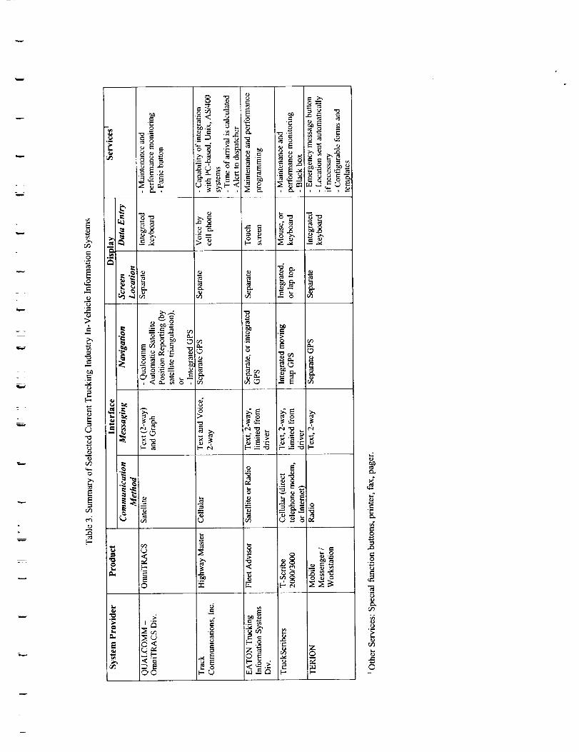
According to this market search, in the trucking industry, the communication method is generallyeither satellite, cellular, or radio. There are also separate or integrated GPS systems on-board. Textmessages are common for communication between the driver and the dispatcher. Displays are usually
either separate, or integrated into the front panel or a laptop. Data entry is performed by either using atouch screen display, voice by cell phone, or a keyboard. There are a large amount of services provided tothe trucking industry such as maintenance and performance monitoring to the driver, emergency alert,automatic location information to the dispatcher, configurable business forms and templates, optional
printer, fax, pager, special function buttons, and black box.
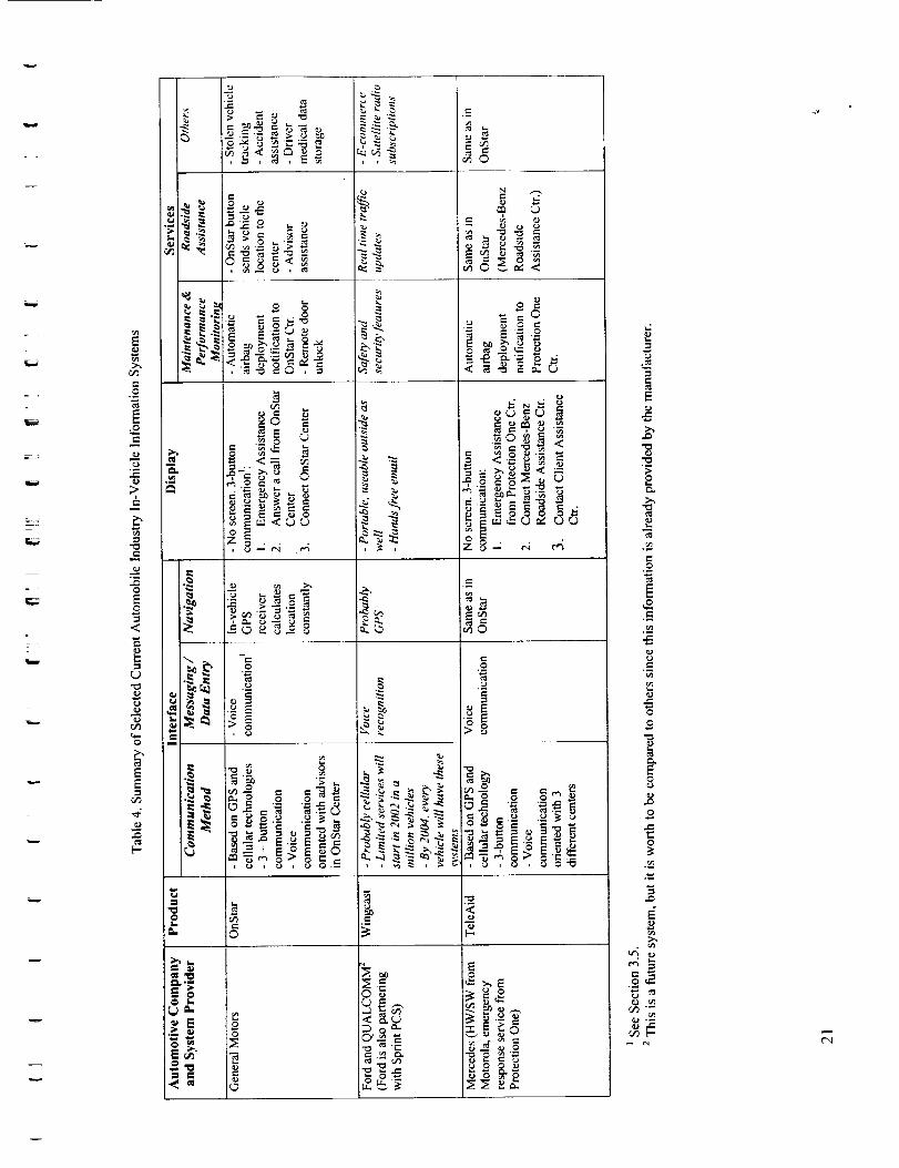
In the automotive industry, the communication method is usually cellular based. Communication isoften provided by either text, or voice messages (by cell phone), or both, generally by communicatingwith an assistance center, which provides most of the information that the driver needs. For navigation,integrated or separate GPS devices are provided. Data entry to the system is usually by using specialfunction buttons. For example, in the General Motors OnStar system, there is a three-buttoncommunication system, one button for emergency assistance, one for answering a call from the OnStarCenter, and another one for connecting to the OnStar Center. System services can be grouped asmaintenance and performance monitoring, roadside assistance, and other services. Automatic airbag
deployment notification to the assistance center is an example of maintenance and performancemonitoring service. Roadside assistance provides information about the road ahead such as traffic updatesand weather information to the driver, and emergency location information to the assistance center. Stolenvehicle tracking, satellite radio subscriptions, driver medical data storage, and e-commerce are some ofthe other services.
A comparative summary of current products used in trucking industry, including selected systemproviders and product descriptions is provided in Table 3. Another comparative summary of currentproducts used in automotive industry, including selected automotive companies and system providerswith product descriptions is provided in Table 4. In both markets, information system products aredivided in three categories: interface, display, and services. The next section examines future
developments on some of these products.
w
-- 19
w
w
._
0-"
_:_ _-_ _ -_ _,_ _,, , , _L, , ,_,_
r._
e_
o "_
r...)
I_, _-
©
o<
m
l:m
d
0
__8
e-
0
r_
e_
r;-,
,.._ e_ e_ I
-__
_. "r"z _ z
lb.
0
,ID
0
.._,
'N
©
w
h
r
w
G_
o
mfj
m
Eo
"0
0
E
0
0
i
_o
I_o_<
_'_o
_ _._,
___
o
0
_ _ ,_._
_,_ _ ._
_ ,_ "__o
E
0
0
.m
0
e_
00
.8
¢-
0
.i
u4
-- rl C',I
w
3.5 Future Developments on Existing Products
This section examines future developments that are being planned by the information systemsproviders for the trucking industry, and by the automotive companies that partner with system providers.This information is derived from Intemet sources such as company web sites, ITSA newsletters,magazines, press releases, and a number of interviews with system provider companies. The datesprovided in this section and in upcoming sections are subject to change according to the developmentlevels of the products at the time this report is submitted. Some of the following information may actuallyexist on the submittal date due to rapid development in this market, while some of it may be delayed.
Information system providers in the trucking industrydevelopments areas for their products in the future:• Intemet access on-board
• Traffic information services integrated with route optimization
• Increased capacity and baud rates
• Voice recognition
are considering the following key
Systems used in the trucking industry are provided primarily by information system companies, whileautomotive companies often prefer to build partnerships with information system providers for theirproducts including on-board information systems. For example, Ford partners with Qualcomm, which isan information system provider for the trucking industry as well (see Table 3). This partnership resulted
in the Wingcast system. Similarly, Mercedes obtains hardware and software from Motorola, andemergency response service from Protection One, for its TeleAid system. Some of the future
developments being considered in the automotive industry are described below:
General Motors - OnStar Messaging / Data Entry Future Developments (in 2001): Hands Free VoiceCommunication:
• Integrated into the front panel.
• Voice recognition for phoning, as well as for other communications with Virtual Advisor (throughcertain predefined commands).
General Motors -OnStar Display Future Developments (in 2001): Virtual Advisor:
• Intemet access through Virtual Advisor: A previously customized web page is needed. VirtualAdvisor downloads it and relays it to the driver via speech recognition technology.
• Personalized information on the web page: email, stocks, sports, news, and weather.• Weather: There is additional weather information via a touch button. Current forecast, or alert
conditions are provided.
Motorola -Jaguar (all Jaguars in 2001)." Timeport wireless phone and communications system.• Access to Intemet content on the system's microbrowser, traffic, maps, weather, news, and other
information.
Delphi Automotive Systems (in December 2000)." Installation of Mobile Productivity Centers to anyvehicle.
• A docking station for a PDA or a cell phone.
• Enables downloading emails, responding by voice commands, and uploading phone numbers andaddresses.
-- 22
w

The previous chapters have provided a base on current on-board information systems, their featuresand developments. Chapter 4 discusses selected enabling communications technologies that supportedpresent systems and will provide a basis for future products.
w
L
w
w 23
E -'
L
4 Enabling Communications Technologies
This chapter examines enabling communication technologies such as wireless data networks, anddevice technologies for wireless connectivity. These technologies are selected according to their possibleapplication in GA cockpit information systems, and their growing demand potential, considering their
characteristics today and developments in the future.
4.1 Wireless Data Networks
The developments in mobile communication systems are supporting a progression from voice onlynetworks to networks providing broadband multimedia services to meet the diverse information and
communication requirements of the mobile community. Data transmission is important because itrepresents an accurate and efficient means of communication. Initially, voice band modems were able totransmit data over first generation analog radio networks with speeds of up to 300 bps. With advances intechnology, data transmission over first-generation analog cellular networks is now able to achieve speedsup to 14.4 kbps. With the first-generation analog networks, data transmission was only an option.However, second and third generation digital cellular radio networks have data communication capabilityas a standard feature. The timeline shown below maps the advent of mobile data:
• 1890's• 1920's• 1940's• 1960's• 1970's• 1980's
• 1990's
• 2000's
- Marconi's first radio transmission
- First pagers (non-commercial use)- AT&T Mobile Telephone Service (MTS)
- Improved MTS- First generation cellular (e.g. AMPS)
- Commercial-use pagers- Low to Medium-speed wireless data- CDPD (19 kbps), 2G digital cellular (9.6 kbps), 1G wireless LAN (2-4 Mbps).- Medium to high-speed wireless data- 2.5G digital cellular (< 384 kbps), 3G digital cellular (< 2 Mbps), 2G wireless LAN (10-155Mbps), Bluetooth 2 (10-20 Mbps), HomeRF (10-20 Mbps), Wireless Cable (10-100 Mbps).
Data can not only transmit more information in a given time than voice, but also provides means fordocumentation, such as dispatch centers recording fleet tracking and driver messages. The number ofapplications for mobile data are growing and aside from traditional users such as courier companies, taxi
dispatches, and transportation companies for fleet management, it is gaining a wider consumer base. Oneof the major application areas is in information or data base retrieval. This is particularly useful whenaccess to specific records is required, such as in the medical field where ambulances can access patients'records and prepare the hospital for the emergency. Also police vehicles armed with data capability are
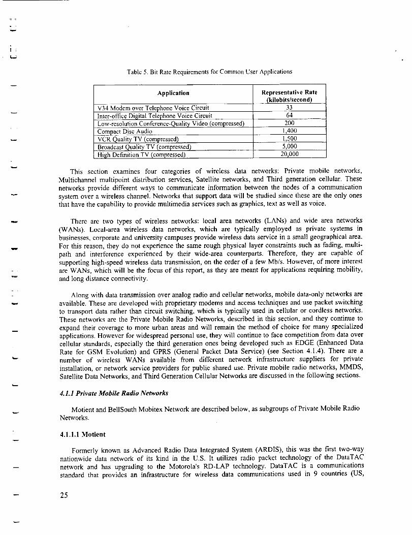
able to look up vehicle registration details or criminal records, and field personnel may retrieve pricinginformation. The data rate requirements for a variety of wireless and wireline services are included in
Table 5 for comparison.
24
w
w
w
Table 5. Bit Rate Requirements for Common User Applications
Application
V34 Modem over Telephone Voice Circuit
Inter-office Digital Telephone Voice CircuitLow-resolution Conference-Quality Video (compressed)
Compact Disc AudioVCR Quality TV (compressed)
Broadcast Quality TV (compressed)High Definition TV (compressed)
Representative Rate__kilobits/second)
33
64200
1,4001,500
5,00020,000
This section examines four categories of wireless data networks: Private mobile networks,
Multichannel multipoint distribution services, Satellite networks, and Third generation cellular. These
networks provide different ways to communicate information between the nodes of a communication
system over a wireless channel. Networks that support data will be studied since these are the only ones
that have the capability to provide multimedia services such as graphics, text as well as voice.
There are two types of wireless networks: local area networks (LANs) and wide area networks
(WANs). Local-area wireless data networks, which are typically employed as private systems in
businesses, corporate and university campuses provide wireless data service in a small geographical area.
For this reason, they do not experience the same rough physical layer constraints such as fading, multi-
path and interference experienced by their wide-area counterparts. Therefore, they are capable of
supporting high-speed wireless data transmission, on the order of a few Mb/s. However, of more interest
are WANs, which will be the focus of this report, as they are meant for applications requiring mobility,
and long distance connectivity.
Along with data transmission over analog radio and cellular networks, mobile data-only networks are
available. These are developed with proprietary modems and access techniques and use packet switching
to transport data rather than circuit switching, which is typically used in cellular or cordless networks.These networks are the Private Mobile Radio Networks, described in this section, and they continue to
expand their coverage to more urban areas and will remain the method of choice for many specializedapplications. However for widespread personal use, they will continue to face competition from data over
cellular standards, especially the third generation ones being developed such as EDGE (Enhanced Data
Rate for GSM Evolution) and GPRS (General Packet Data Service) (see Section 4.1.4). There are anumber of wireless WANs available from different network infrastructure suppliers for private
installation, or network service providers for public shared use. Private mobile radio networks, MMDS,
Satellite Data Networks, and Third Generation Cellular Networks are discussed in the following sections.
4.1.1 Private Mobile Radio Networks
Motient and BellSouth Mobitex Network are described below, as subgroups of Private Mobile Radio
Networks.
4.1.1.1 Motient
Formerly known as Advanced Radio Data Integrated System (ARDIS), this was the first two-waynationwide data network of its kind in the U.S. It utilizes radio packet technology of the DataTAC
network and has upgrading to the Motorola's RD-LAP technology. DataTAC is a communications
standard that provides an infrastructure for wireless data communications used in 9 countries (US,
-- 25
L
W
Canada, Australia, Germany, Switzerland, Singapore, Thailand, Hong Kong and Malaysia). It wasoriginally created and jointly owned by Motorola and IBM to serve IBM field technicians. In 1995,Motorola acquired 100% ownership of ARDIS, and ARDIS was acquired by the American MobileSatellite Corporation in 1998. ARDIS is quoted as covering 90% of the urban business population and
more than 400 metropolitan areas in the United States, Puerto Rico, and the Virgin Islands with anestimated 40,000 users (ref. 13). The mobile communication device is the RIM wireless handheld thatfeatures wireless data service and the cLink wireless e-mail that is always connected to receive e-mail
without having to dial up. The satellite service provides the extended coverage and is used in theMobileMAX product of Motient, which combines land-based and satellite technology to provide datamessaging, asset and freight tracking and fleet management capabilities.
Motorola has developed two proprietary air-interface protocols for the ARDIS packet network: theMDC-4800, which provides up to 4,800 b/s service, and the RD-LAP, which provides up to 19,200 b/s
service. MDC-4800 service has been deployed throughout the ARDIS network but most major serviceareas have now been enhanced with RD-LAP capability. The operating frequency band is 800 MHz andthe RF links use separate transmits and receive frequencies, 45 MHz apart, that are simultaneously used to
form a full-duplex channel. ARDIS was initially implemented with a RF channel data rate of 4800 b/s per25 kHz channel, but it has been upgraded to 19,200 b/s in some service areas. The base station power isapproximately 40 W, which provides line-of-sight coverage up to a radius of 10 to 15 miles. On the otherhand, the radio terminals operate with 4 W of radiated power. The areas covered by the individual basestations overlap to increase the probability of a signal from a radio terminal reaching at least one basestation. The overlapping coverage, combined with designed power levels and error-correction coding inthe transmission format, insures that ARDIS can support portable communications from inside buildings,as well as outside. This capability for in-building coverage is an important characteristic of the ARDISservice (ref. 13).
Inside every cell, the radio terminals access the network by using a random method called Data Sense
Multiple Access (DSMA). Before every transmission, a radio terminal listens to the base stationtransmitter to determine whether a "busy bit" is on or off. This bit indicates whether the base station iscurrently receiving data (busy bit is on) or not (busy bit is off), and it encodes the current state of the
shared uplink channel (ref. 13). When this bit is on, radio terminals are prohibited from transmitting;therefore the packet collisions are avoided. On the other hand, when the busy bit is off, a radio terminal isallowed to transmit. However, if two terminals happen to begin transmission at the same time, the packetscollide and retransmission is attempted (ref. 13).
4.1.1.2 BellSouth Mobitex Network
Bell South Wireless Data operates a mobile packet radio data network that provides remote access todata and two-way messaging for mobile computing applications. The technology on which this network isbased is Mobitex from Ericsson. In 1999, there were public Mobitex networks in operation in at least 15countries on four continents. Mobitex is a worldwide standard, introduced by Swedish Telecom, now
called Telia Mobitel, and controlled and administered by Ericsson Mobile Communications and the
Mobitex Operators Association (MOA). All Mobitex networks use the same protocols and operate underthe same specifications. The MOA oversees the specifications, coordinates software and hardwaredevelopment, and evolves the technology. The specifications are published by the MOA without anylicense or fee, thus there are many terminal suppliers and equipment developers (ref. 14). EuropeanMobitex operators are now introducing international roaming, a service that will allow Mobitex users tocontinue to send and receive messages and access data outside their home countries.
In the United States, Mobitex technology was introduced by RAM Mobile Data, a company that wasoriginally formed in 1989 as a joint business venture between BellSouth and RAM Broadcasting
-- 26
_...z
r .
mm
Corporation. Today, RAM Mobile Data is owned by BellSouth, with a nationwide system with more than1200 base stations installed. The service is provided in more than 7700 cities and towns, coveringapproximately 93% of America's urban business population, and more than 11,000 miles of interstatehighway, with automatic seamless roaming across all service areas. Furthermore, additional coverage is
being implemented in order to expand the service area in the near future (ref. 15).
The Mobitex system employs a cellular layout in order to provide wireless communication services toa specific geographical area. It utilizes a hierarchical structure that may contain up to six levels ofnetwork nodes, depending on the size and the area of coverage. The infrastructure comprises three typesof nodes: base stations (base), local switches, and regional switches. The cells served by the same localswitch form a service area or a subnet. In each service area 10 to 30 frequency pairs (called channels) areallocated to radio service (ref. 14). Each base station typically utilizes from one to four channels,depending on the anticipated cell loading. All these channels have 12.5 kHz bandwidth and support a datarate of 8 kb/s. Mobitex networks in the US generally operate at 900 MHz.
A Mobitex network can be configured in many different ways, from a large public network providingnationwide coverage to a small, privately owned network serving a single company or region and can be
applied to mobile or fixed applications. Mobitex can give access to corporate resources and extend acompany's fixed networks, such as query a central database or monitor and control equipment in a remotelocation, as well as access to the Internet. Devices such as two-way pagers, laptops and PDAs are able toaccess the network. The new 3Com Palm VII uses the Mobitex network for wireless e-mail.
4.1.2 Multichannel Mui@oint Distribution Service (MMDS)
MMDS, also known as wireless cable, is a relatively new form of broadcasting and communicationsservice. It enables the user to have a series of channels re-transmitted from satellites and ground stations
with excellent image quality. Although this is still a relatively new form of transmission, the use ofMMDS is growing significantly throughout the world.
MMDS transmitters consist of components very similar to those normally used for television bands(AM modulation), integrated with power amplification stages operating in the 2-GHz range and requiringhigh linearity characteristics (class "A"). It was conceived as a substitute for conventional cable
television; however, it has applications in telephone/fax and data communications. In MMDS, a medium-power transmitter is located with a broadcast antenna at or near the highest topographical point in theintended coverage area. The workable radius can reach up to 70 miles in flat terrain (significantly less inhilly or mountainous areas). Each subscriber is equipped with a small antenna, along with a converter that
can be placed next to, or on top of, a conventional TV set. There is a monthly fee, similar to that forsatellite TV service. The MMDS frequency band has room for several dozen analog or digital videochannels, along with narrowband channels that can be used by subscribers to transmit signals to thenetwork. The narrowband channels were originally intended for use in an educational setting (so-called
wireless classrooms).
Because of recent deregulation that allows cable TV companies to provide telephone and Intemetservices, along with the development of digital technologies that make efficient use of availablebandwidth, MMDS has considerable future potential. A MMDS network can provide high-speed Intemet
access, telephone/fax, and TV together, without the constraints of cable connections (www.wcai.com).
4.1.3 Satellite Data Networks
Satellite systems are established providers of fixed communication services including wireless WANsand VSAT (Very Small Aperture Terminal) networks. Of more interest to mobile users are some of the
-- 27
w
ambitious large-scale networks comprised of LEO (Low Earth Orbit) or MEO (Medium Earth Orbit)
satellite constellations and ground stations that are being launched aiming to provide broadband
multimedia services. Some of the advanced satellite technologies that make this possible are switched
spot beams, on-board processing and special orbits. Teledesic, Globalstar, Inmarsat, and Connexion by
Boeing are subgroups of Satellite Data Networks, and are discussed below, including the services offered,
terminals, coverage and costs. Propagation effects in mobile satellite systems are also included.
4.1.3.1 Teledesic
Teledesic is a global broadband data network (Internet-in-the-Sky) to provide worldwide, fiber-likeaccess to telecommunications services such as computer networking, broadband Intemet access,
interactive multimedia, and high-quality voice, through Low Earth Orbiting (LEO) constellation of
satellites. It is expected to cover nearly 100% of the Earth's population, and 95% of the landmass. This
network whose objectives are to reach low latency, low error rates, high service availability, and flexible,
broadband capacity, while serving as the access link between users or networks, is targeted to begin
operating in 2005.
The Teledesic network consists of a space segment (the satellite-based switch network that provides
the communication links among terminals) and a ground segment (terminals, network gateways and
network operations and control systems). Terminals provide the interface both between the satellite
network and the terrestrial end-users and networks. They perform the translation between the Teledesic
Network's internal protocols and the standard protocols of the terrestrial world, thus isolating the satellite-
based core network from complexity and change (Figure l). Most users will have two-way connectionsthat provide up to 64 Mbps on the downlink and up to 2 Mbps on the uplink. The system enables the use
of small, low-power user equipment to send and receive data. The fixed user equipment will mount on a
rooftop and connect inside to a computer network or PC. Broadband terminals will offer 64 Mbps of two-
way capacity. This represents access speeds up to 2,000 times faster than today's standard analogmodems.
Teledesic's ability to handle multiple channel rates, protocols and service priorities provides the
flexibility to support a wide range of applications including the Internet, corporate intranets, multimedia
communication, and LAN interconnect. Teledesic's space-based network uses fast-packet switching.
Communications are treated within the network as streams of short, fixed-length packets. Each packet
contains a header that includes destination address and sequence information, an error-control section
used to verify the integrity of the header, and a payload section that carries the digitally encoded user data
(voice, video, data, etc.). Conversion to and from the packet format takes place in the terminals. From a
network viewpoint, a large constellation of interlinked switch nodes offers a number of advantages interms of service quality, reliability and capacity. The richly interconnected mesh network is a robust,
fault-tolerant design that automatically adapts to topology changes and to congested or faulty nodes and
links. To achieve high system capacity and channel density, each satellite is able to concentrate a large
amount of capacity in its relatively small coverage area. Overlapping coverage areas plus the use of on-
orbit spares permit the rapid repair of the network when a satellite failure results in a coverage gap. In theinitial constellation, the Teledesic network will consist of 288 operational satellites, divided into 12
planes, each with 24 satellites.
-- 28
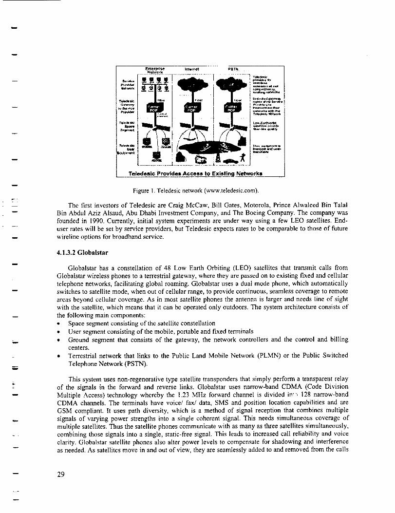
w
W
!
m
w
S_l,u_rall
T*kP_
User
_t
PSTN
T_de_
u_w_K, vd_9
_merprig__h_r._a rk
Tel______ededes_cProvides Access to Existing Networks
Figure 1. Teledesic network (www.teledesic.com).
The first investors of Teledesic are Craig McCaw, Bill Gates, Motorola, Prince Alwaleed Bin TalalBin Abdul Aziz Alsaud, Abu Dhabi Investment Company, and The Boeing Company. The company wasfounded in 1990. Currently, initial system experiments are under way using a few LEO satellites. End-user rates will be set by service providers, but Teledesic expects rates to be comparable to those of futurewireline options for broadband service.
4.1.3.2 Globalstar
Globalstar has a constellation of 48 Low Earth Orbiting (LEO) satellites that transmit calls from
Globalstar wireless phones to a terrestrial gateway, where they are passed on to existing fixed and cellulartelephone networks, facilitating global roaming. Globalstar uses a dual mode phone, which automaticallyswitches to satellite mode, when out of cellular range, to provide continuous, seamless coverage to remoteareas beyond cellular coverage. As in most satellite phones the antenna is larger and needs line of sightwith the satellite, which means that it can be operated only outdoors. The system architecture consists of
the following main components:• Space segment consisting of the satellite constellation
• User segment consisting of the mobile, portable and fixed terminals• Ground segment that consists of the gateway, the network controllers and the control and billing
centers.
• Terrestrial network that links to the Public Land Mobile Network (PLMN) or the Public Switched
Telephone Network (PSTN).
This system uses nonmregenerative type satellite transponders that simply perform a transparent relayof the signals in the forward and reverse links. Globalstar uses narrow-band CDMA (Code Division
Multiple Access) technology whereby the 1.23 MHz forward channel is divided in::, 128 narrow-bandCDMA channels. The terminals have voice/ fax/data, SMS and position location capabilities and are
GSM compliant. It uses path diversity, which is a method of signal reception that combines multiplesignals of varying power strengths into a single coherent signal. This needs simultaneous coverage ofmultiple satellites. Thus the satellite phones communicate with as many as three satellites simultaneously,combining those signals into a single, static-free signal. This leads to increased call reliability and voiceclarity. Globalstar satellite phones also alter power levels to compensate for shadowing and interferenceas needed. As satellites move in and out of view, they are seamlessly added to and removed from the calls
-- 29
v
w
w
w
in progress, reducing call interruption. The Globalstar protocol uses pilot assisted acquisition and powercontrol (ref. 16).
4.1.3.3 Inmarsat
Inmarsat has been providing global voice and low rate data communications since 1982 and hascontinued to expand with additional satellite launches and evolved its aeronautical services with Aero-C,Aero-H, Aero-I, and Aero mini-M, which are designed to exploit the spotbeam power of the Inmarsat-3satellites. The latest development in the Inmarsat network allows connection to a terrestrial ISDNnetwork, leading to the 'mobile-IDSN' concept. ISDN (Integrated Services Data Network) is acommunication network that uses digital technology to integrate voice, video and data on a single system.
Based on digital satellite technology via spotbeam, the Global Mobile ISDN Service offers not only a
single service, but a complete system solution as well. The mobile satellite services are designed toconnect fixed and mobile networks and close existing gaps in the telecommunications infrastructure. Thecapabilities are being designed to integrate corporate IT networks with global mobile satellitecommunications. It includes voice, fax and data transmission at speeds of up to 2.4 Kbps, as well as
access to data transmission up to 64 Kbps (High Speed Data/HSD). In a second step, Inmarsat will launchthe first and only mobile-satellite packet data service later in 2001 (Inmarsat Packet Data System, IPDS).
The Global Mobile ISDN introduces new applications for mobile users such as e-mail transfer,Internet and Intranet access, LAN applications, file and image transfer, video conferencing and remoteworking. It uses new portable units the size of a notebook computer and weighing around 4kg (91bs).COMSAT is one of the companies that are developing networks and terminals for this service. It uses thelnmarsat satellite network and the Nera M4 satellite terminal to allow users to connect to low cost voice
services as well as high-speed data services at data rates up to 64 kbps. By using standard ISDN
interfaces, they will give access to a full range of desktop software via Inmarsat satellites.
4.1.3.4 Connexion by Boeing sM
Connexion by Boeing uses a satellite network to provide high-speed, two-way Internet and livetelevision services, news and information to aircraft in flight, for about the same price as cellular phoneservices. Through this service, two-way, broadband (or high data-rate) connectivity will be delivereddirectly to the passengers with personalized and secure access to the Interact, company Intranets and livetelevision and audio content. Connexion by Boeing will also provide airline personnel with informationthat will enhance operational efficiency on the ground and in the air (ref. 17).
The Connexion by Boeing service is currently available to the private business jet market. Systeminstallations on-board commercial airlines are expected to begin in 2001. Initial service will cover travelroutes across North America and the service will be expanded to other global flight routes with anongoing regional rollout through 2005. Specifically, Connexion by Boeing will serve three marketsegments below (as the service matures it will be extended to additional markets including commercialand leisure cruise ships and oil exploration platforms):
• Commercial airlines and their passengers
• Private business jets
• Government customers
--- 30
w
w
w
w
h
y
w
Digital broadband capability, which provides increased bandwidth for two-way interactive
applications, allows customers to send and receive data at rates equivalent to cable Internet access. To
provide the capability to airborne travelers, Boeing will use advanced antenna technology and existing
satellites, while extending to a mix of new and existing satellites as the service matures.
Customer airplanes will be equipped with the Boeing proprietary phased array receive and transmit
antenna, a key enabler for two-way broadband communications. Initially developed by Boeing in 1986,
the antenna technology provides a dramatic increase in data transmission capability over that currentlyexisting today. The Boeing phased array antenna provides enhanced response to directional changes by
steering signals electronically vs. mechanically, permitting instantaneous and continuous connectionsbetween satellites and customer aircraft.
4.1.3.5 Propagation Effects in Mobile Satellite Systems
There are special problems in the mobile-satellite services that are unique to them. For the land-
mobile-satellite service, these problems involve effects of foliage, terrain, and man-made structures. For
the aeronautical-mobile-satellite service, the issues involve long delayed echoes from the earth's surface.
For aeronautical service, the altitude of the aircraft may be above most tropospheric attenuation and
therefore airborne receivers will have an advantage over terrestrial receivers in receiving satellite signals.
Ionospheric effects will be the same as for other service categories.
Satellite communications has the drawback that it requires direct line-of-sight (LOS) with the satellite
and continuous tracking. While the tracking can be done with software and the antenna can remain fixed,
the operation is limited to outdoor use. In addition, satellite signals can be weak and can thus require
bigger antennas. However, these larger antennas can be detachable and improve the ease of installation.
4.1.4 Satellite Digital Audio Radio Services (S-DARS)
Direct broadcast satellite has been deployed in the last decade or so to deliver television broadcasting
directly to homes from satellites via a VSAT (Very Small Aperture Terminal). This technology is now
moving to the radio arena with direct broadcast of radio stations via satellite to mobile terminals in the
vehicle. Thus a multitude of programmable digital channels will be broadcast directly from satellites to
small, portable satellite receivers. Programming will be uplinked from ground stations to the satellites and
then broadcast back to the subscribers on the ground (refs. 18, 19).
Programming choices range from news to entertainment to education. This is an interesting aspect of
S-DARS - that due to the multitude of channels, dedicated channels may be allocated to various content
providers, who are in charge of the programming for that channel. This means a sports channel with only
sports and a weather channel with only weather available at all times. Another important feature is that
the extensive coverage of the satellites in the geostationary orbit ensures a uniform, good broadcast
quality with no fading over the entire continental United States and that these channels are alwaysavailable at the same frequency everywhere with no need for tuning. The coverage aspect is the biggest
advantage of S-DARS in terms of aeronautical application where en-route weather updates and warnings
are required. Similar to the conventional radio, S-DARS is a one-way broadcast system.
The progress of this new technology began in 1992 when the FCC allocated spectrum in the "S" band
(2.3 GHz) for nationwide broadcasting of satellite-based Digital Audio Radio Service (or "DARS")
(ref.20). In 1997 the FCC had a spectrum auction and awarded licenses to two companies, CD Radio and
XM Satellite Radio Inc. - formerly the American Mobile Radio Corporation.
-- 31
w
L_
w
w
4.1.4.1 Companies offering S-DARS
CD Satellite Radio, which is operating under the trademark Sirius Satellite Radio has launched three
satellites and plans to deliver 50 channels of commercial-free music in virtually every genre, and up to 50channels of news, sports, talk, comedy and children's programming. They will charge a monthlysubscription fee of $12.95 for this service. CD Radio's signal will be uplinked from a broadcast studio thatwill house the company's music libraries and facilities for programming and satellite uplinking.
The other operator, XM Satellite Radio has similar capabilities offering up to 71 music channels and29 other channels featuring talk, news, sports and entertainment for a monthly subscription of $9.99.Service is expected to be launched on September 10, 2001 in a few selected areas and November 12, 2001
nationwide. Both companies plan to employ terrestrial repeaters in major cities where buildings wouldblock satellite reception.
A major thrust of both companies' business plans is to develop alliances with the major automobilemanufacturers to build DBS-capable radios into new automobiles. XM Satellite Radio has an agreementin place with General Motors (GM), and Sirius Satellite Radio has agreements in place with Ford andDaimler-Chrysler. Both companies also have agreements in place with major radio manufacturers.
The equipment to receive the satellite signal will consist of an AM/FM/SAT receiver and a small, flat;2" disk antenna will be attached to the windshield of the car. For use with existing equipment, a specialadaptor card that is designed to slip into the cassette slot of the car stereo will be available. A small LCDpanel will be available on new systems or attached to the card to display specific information about thebroadcast. The technology to decode signals from a remote satellite, while the receiver is moving at a
speed of 80 - 90 Mph, as well as deciphering the authorization information for the subscriber, is veryadvanced. Chip-sets for the new radio have to be capable of decoding of compressed data that will beused to squeeze up to 100 channels into a limited radio spectrum (ref. 21). The cost of equipment will befrom $200 to $400 depending on the manufacturer.
Another company, Worldspace, currently delivers a satellite radio service to Africa, Asia, and theMiddle East through the company's two L-band satellites, AfriStar and AsiaStar. The company plans onexpanding their service to Latin America and the Caribbean sometime in 2001 with the launch ofAmeriStar (ref. 22).
4.1.4.2 Future Planned Capabilities of S-DARS
The current systems do not have the capability for transmitting data and two-way request/replyservices but due to the digital nature of the signals, receivers could be built to decode and display textualdata in the future (refs. 23, 24). Both companies say that they are considering upgrading the system in thefuture to have possible integration of a Global Positioning System in the satellite radio receivers, and
filtering the information content based on the position of the user to display location-sensitive informationsuch as weather reports and traffic conditions. XM Radio and OnStar are also partnering together and inthe next three years plan to develop a way to communicate between the two systems and use the highercapacity and speed of the satellite transmission to provide enhanced services to OnStar subscribers. Theallocation of 2 - 3 channels to OnStar and the possibility of linking the user to the XM ground station viathe OnStar centers will allow programmable content delivery and 2-way capability to be added to thesystem (ref. 24).
w
32
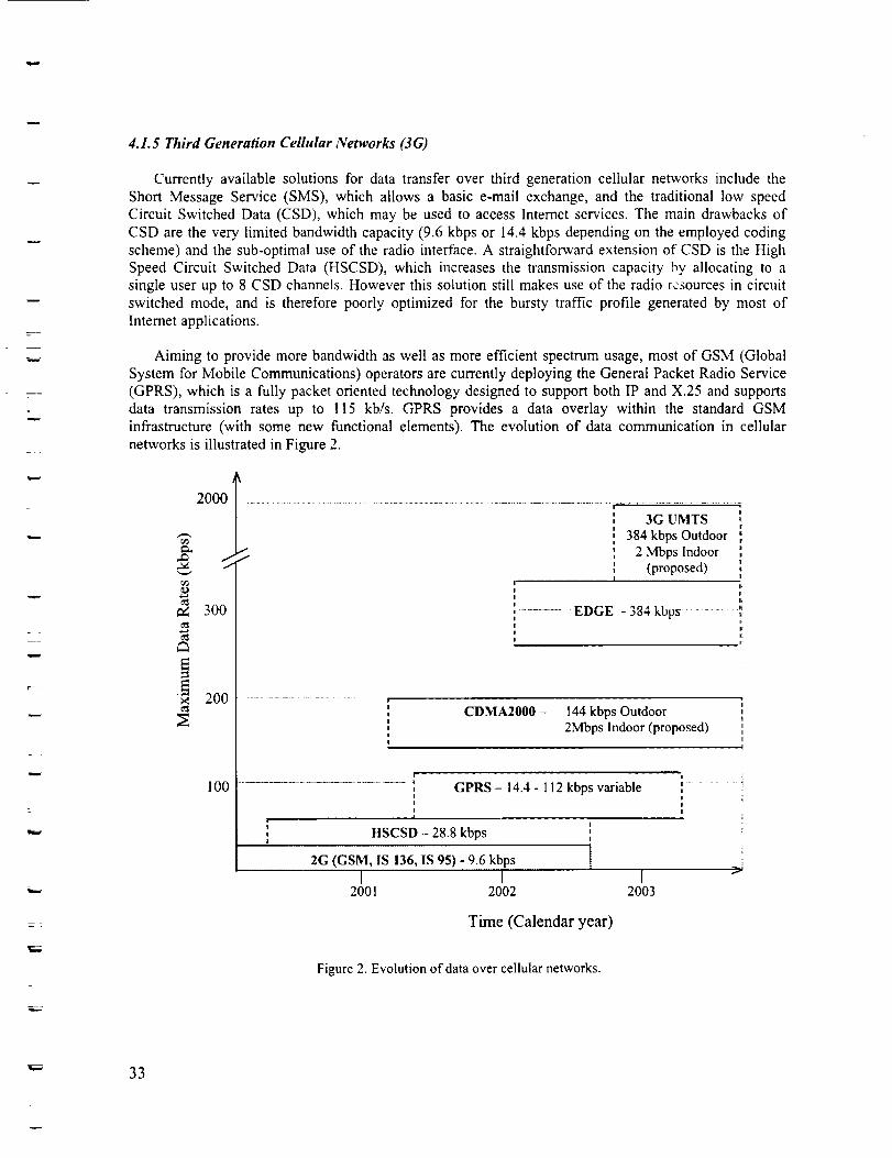
w
r-" :
E
w
= w
=
4.1.5 Third Generation Cellular Networks (3G)
Currently available solutions for data transfer over third generation cellular networks include the
Short Message Service (SMS), which allows a basic e-mail exchange, and the traditional low speed
Circuit Switched Data (CSD), which may be used to access Interact services. The main drawbacks of
CSD are the very limited bandwidth capacity (9.6 kbps or 14.4 kbps depending on the employed coding
scheme) and the sub-optimal use of the radio interface. A straightforward extension of CSD is the High
Speed Circuit Switched Data (HSCSD), which increases the transmission capacity _y allocating to a
single user up to 8 CSD channels. However this solution still makes use of the radio resources in circuit
switched mode, and is therefore poorly optimized for the bursty traffic profile generated by most of
Interact applications.
Aiming to provide more bandwidth as well as more efficient spectrum usage, most of GSM (Global
System for Mobile Communications) operators are currently deploying the General Packet Radio Service
(GPRS), which is a fully packet oriented technology designed to support both IP and X.25 and supports
data transmission rates up to !15 kb/s. GPRS provides a data overlay within the standard GSM
infrastructure (with some new functional elements). The evolution of data communication in cellular
networks is illustrated in Figure 2.
2000 ..................................................................i
3G UMTS384 kbps Outdoor _
_ 2 Mbps Indoor(proposed) i
I-!
300 ........... EDGE - 384 kbps - _!
200
100
i
CDMA2000 - 144 kbps Outdoor2Mbps Indoor (proposed)
GPRS - 14.4 - 112 kbps variable
, HSCSD - 28.8 kbps ',
2G (GSM, IS 136, IS 95) - 9.6 kbps [I I
2001 2002
!, i!
!
I2003
Time (Calendar year)
Figure 2. Evolution of data over cellular networks.
33
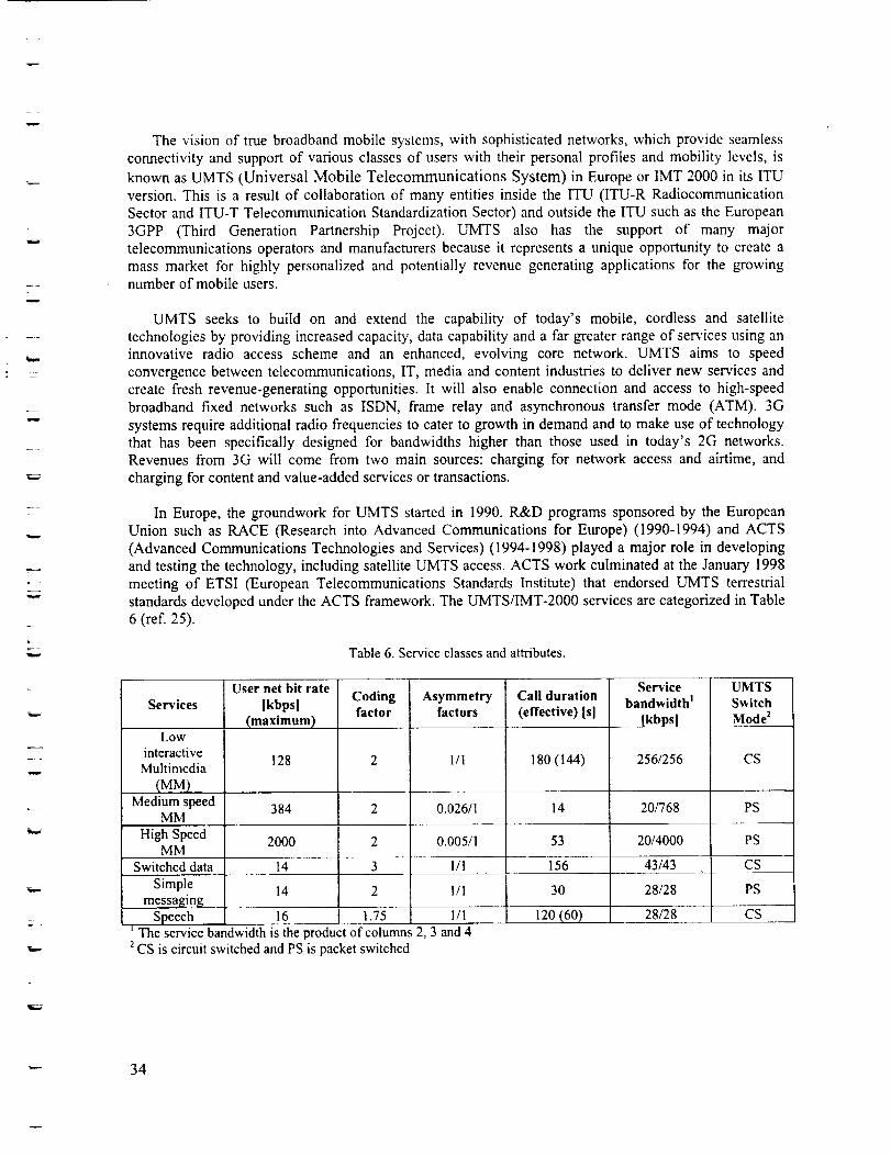
w
--=
w
The vision of true broadband mobile systems, with sophisticated networks, which provide seamless
connectivity and support of various classes of users with their personal profiles and mobility levels, is
known as UMTS (Universal Mobile Telecommunications System) in Europe or IMT 2000 in its ITU
version. This is a result of collaboration of many entities inside the ITU (ITU-R Radiocommunication
Sector and ITU-T Telecommunication Standardization Sector) and outside the ITU such as the European
3GPP (Third Generation Partnership Project). UMTS also has the support of many major
telecommunications operators and manufacturers because it represents a unique opportunity to create a
mass market for highly personalized and potentially revenue generating applications for the growingnumber of mobile users.
UMTS seeks to build on and extend the capability of today's mobile, cordless and satellite
technologies by providing increased capacity, data capability and a far greater range of services using an
innovative radio access scheme and an enhanced, evolving core network. UMTS aims to speed
convergence between telecommunications, IT, media and content industries to deliver new services and
create fresh revenue-generating opportunities. It will also enable connection and access to high-speed
broadband fixed networks such as ISDN, frame relay and asynchronous transfer mode (ATM). 3G
systems require additional radio frequencies to cater to growth in demand and to make use of technology
that has been specifically designed for bandwidths higher than those used in today's 2G networks.Revenues from 3G will come from two main sources: charging for network access and airtime, and
charging for content and value-added services or transactions.
In Europe, the groundwork for UMTS started in 1990. R&D programs sponsored by the European
Union such as RACE (Research into Advanced Communications for Europe) (1990-1994) and ACTS
(Advanced Communications Technologies and Services) (1994-1998) played a major role in developing
and testing the technology, including satellite UMTS access. ACTS work culminated at the January 1998
meeting of ETSI (European Telecommunications Standards Institute) that endorsed UMTS terrestrial
standards developed under the ACTS framework. The UMTS/IMT-2000 services are categorized in Table
6 (ref. 25).
Table 6. Service classes and attributes.
Services
Low
interactiveMultimedia
(MM)Medium speed
MM
User net bit rate
[kbps]
(maximum)
128
Codingfactor
Asymmetryfactors
1/1
Call duration
(effective) Isl
18o (144)
Servicebandwidth _
[kbpsl
256/256
UMTSSwitchMode 2
CS
384 2 0.026/1 14 20/768 PS
High Speed 2000 2 0.005/1 53 20/4000 PSMM
Switched data 14 3 I/1 i 56 43/43 CS
Simplemessaging
Speech 1.75
14 30 28/28
120 (60)16
I/1 PS
I/1
The service bandwidth is the product of columns 2, 3 and 42CS is circuit switched and PS is packet switched
28/28 CS
---- 34
m
+w
=w
4.1.5.1S-UMTS
S-UMTS is the Satellite component of the UMTS. It is expected to handle various forms of
information such as speech (voice), image and data, and will provide an extension to the terrestrial 3Gwireless networks. Due to the differences between terrestrial and satellite channel characteristics, somemodifications to the terrestrial UMTS standards are necessary. Some specifications are directly
applicable, whereas others are applicable with modifications.
The ETSI S-UMTS Technical Specifications are comprised of several parts:
• Part 1: Physical channels and mapping of transport channels into physical channels (S-UMTS-A25.211)
• Part 2: Multiplexing and channel coding (S-UMTS-A 25.212)
• Part 3: Spreading and modulation (S-UMTS-A 25.213)
• Part 4: Physical layer procedures (S-UMTS-A 25.214)
MSS (Mobile Satellite Services), which is one of the application areas of S-UMTS, have been
categorized as follows:
1. Speech - quality basic speech at 8/16 kbit/s
2. Low-speed data - predominantly messaging and e-mail (without attachments) type services at9.6/16 kbit/s
. Asymmetric services - this includes the predominantly one way services including file transfer,database/LAN access, Intranet/Intemet WWW, E-mail (with attachments), image transfer etc.Rates of transmission will be up to around 144 kbit/s. This corresponds approximately to the
Medium (and High) Multimedia services defined for terrestrial UMTS/IMT-2000
, Interactive Multimedia - predominantly relating to videoconferencing and videotelephony at data
speeds of around 144 kbit/s. This corresponds approximately to the High Multimedia services asdefined for terrestrial UMTS/IMT-2000.
The UMTS is aiming to provide a network capable of supporting many data rates and over-the-airchange in data rates, in response to the type of service requested by the user as well as network conditionssuch as usage. Thus, a user making a file download can request a higher data rate for the period of timethat the network can allow and then switch to a lower data rate when more users connect to the network.
These VDR (Variable Data Rate) services are made possible by enhanced radio architectures and receiver
technologies such as software radios.
In Europe, the definition work for a possible S-UMTS system has been extensively carried out by the
European Union's ACTS (Advanced Communications Technologies and Services) program. The ACTSprogram is framework for EU's research effort to accelerate deployment of advanced communicationsinfrastructures and services and consists of over two hundred individual projects and trials including
MOMUSYS (Mobile Multimedia Systems), TOMAS (Inter-Trial Testbed of Mobile Applications forSatellite Communications) and SINUS (Satellite Integration into Networks for UMTS Services) projects
(ref. 26).
Preliminary results achieved by project SINUS are pushing the state of the art in topics like UMTSintra-satellite segment handover, inter-segment handover and reference models for satellite integrationwith the terrestrial systems. The project is undertaking full characterization of system performance for a
" 35
L
w
w
W
z
W
-=_,,.
variety of mobile environments (suburban, rural, etc.) and support of multimedia applications. Throughtrials, the Ka band satellite concepts recently proposed for FSS (Fixed Satellite Service) applications (by
Teledesic, Spaceway, Cyberstar etc.) have been successfully extended to mobile applications.
Joint trials by a number of ACTS projects have been set up to validate innovations in S-UMTSequipment and services on real mop,de satellite channels. The foremost technology being investigated forS-UMTS is the satellite W-CDMA (Wideband Code Division Multiple Access) - the European Space
Agency (ESA) is working on Radio Transmission Technology (RTT) which is the adaptation of UMTSW-CDMA to the satellite environment. Code Division Multiple Access (CDMA) scheme is being testedby SINUS because it offers several benefits over other schemes and maximum compatibility with the
terrestrial W-CDMA mode. The proposed trials aim at covering a whole range of orbits, from LEO (780km) up to GEO, with use of variable parameters (e.g. for power control or interleaving depth). Beyond theneed to harmonize the satellite access with terrestrial solutions, work under both ESA and SINUS project
have concentrated on CDMA for the following reasons:
* Satellite diversity is an essential feature considering the required service availability rates and it iseasy to combine signals from a number of sources such as multiple satellites with CDMA.
• Easier to access to different types of constellations such as LEO or GEO as it is easy to resolve timedelay in CDMA.
• CDMA allows soft handover, which is a seamless handover, achieved with user's terminalcommunicating with both base stations simultaneously.
• Simpler radio resource management, TDMA requires a more complex frequency planning betweenthe satellite spots.
CDMA offers high capacity solutions.
Although extensive W-CDMA technology trials are currently being run by a large number ofoperators for terrestrial UMTS, presently the satellite W-CDMA remains largely untested.
4.2 Device Technologies for Wireless Connectivity
While the data networks described in the previous section provide the infrastructure for thecommunication system, the wireless devices provide the link between the service provider and the enduser's final requirements. "Faster, smaller, better" are the guidelines that have driven the design ofwireless devices. Selected device technologies such as operating systems, air interface ! wireless modem,and Bluetooth are discussed in this section.
4.Z I Operating Systems
There are operating systems specifically developed for handheld and in-vehicle devices that provide
an open architecture for the development of independent and add-on applications. Examples of suchoperating systems are the Windows CE by Microsoft, Palm OS by Palm Inc., and Symbian's Epoc. Thedevelopment platform for real-time tools and applications for mobile devices uses a number of powerful
languages such as Java and Wireless Access Protocol (WAP). Java provides superior usability needed forfunctions such as maps, other navigation applications, and operating system independence. Applicationswritten in Java can run on a variety of devices such as set-top boxes, smart phones, vending machines,and handheld order-entry or inventory devices. An example of application software that can be created
using Java is a keypad on a handheld device, such as a Palm Pilot screen.
_ 36
w
=
w
w
w
4.2.2 Air Interface / Wireless Modem
Air interfaces are the protocols that define the physical layer characteristics of the communicationscheme, and allow the signal to be extracted. The most common air interface is the wireless modem,which is essentially a wireless transceiver that consists of all the RF, modulation/demodulation, analog todigital and digital to analog conversion circuitry necessary to transmit over the channel. Modems aredesigned according to the particular communication scheme used.
One of the most critical components of the wireless modem that affect the transceiver performance isthe RF power amplifier. This component introduces nonlinearities and intermodulation noise, if notdesigned properly. Hence it is one of the most expensive components in a wireless modem. A variety ofcommercial off-the-shelf modems are available for the different communication standards. Another
benefit of modem standardization is that since the same components are used for a variety of differentmanufacturers' devices, the volume is increased, achieving economy of scale.
4.2.3 Bluetooth
The Bluetooth wireless technology allows users to make wireless and instant connections betweenvarious communication devices, such as mobile phones and desktop and notebook computers. Since ituses radio transmission, transfer of both voice and data is in real-time. It supports both point-to-point and
point-to-multipoint connections. It is an RF (radio frequency) -based technology geared toward cable orIR replacement that allows interoperability between different devices.
The Bluetooth radio is built into a small microchip and operates in a globally available frequencyband ensuring communication compatibility worldwide. The Bluetooth specification has two power levels
defined: a lower power level that covers the shorter personal area within a room, and a higher power levelthat covers a medium range, such as within a home.
3Com already has products that include Bluetooth technology (PC Card, USB Adapter, and AccessPoint 1000), which will be available in the first half of 2001. This technology will be used on a broadrange of computers, cell phones, Palm computers, printers, scanners, keyboards, digital cameras, andother devices. All personal digital devices will be connected in the user's personal area network (PAN).For example, a user's handheld device and desktop system will automatically synchronize her/hisschedule and address books while his/her cell phone updates its phone number list.
The historical development of Bluetooth begins with Ericsson Mobile Telecommunications' initiationof a study to investigate the feasibility of a low-power, low-cost radio interface between mobile phonesand their accessories in 1994. The objective on this was to eliminate cables between mobile phones andPC cards, headsets and desktop devices, etc. In February 1998, 5 companies formed a Special InterestGroup (SIG), including Nokia, IBM, Toshiba, and Intel. The mission of the SIG was to define and
promote an open, royalty-free specification for seamless, wireless connectivity and cable replacement fora wide variety of mobility-enhancing devices. Today, the SIG includes promoter companies such as3Com, Ericsson, IBM, Intel, Lucent, Microsoft, Motorola, Nokia and Toshiba, and more than 2000
Adopter/Associate member companies.
37
w
w
w
w
h
4.3 Challenges to Deployment of Wireless Technologies and Some Solutions
Key information on wireless technologies was provided in the previous sections of chapter 4.Vehicular communication systems work in a fast moving mobile environment that introduces a host ofcomplexities not encountered in a fixed or indoor portable environment. An overview of some of the
technical as well as organizational challenges is considered in this section. Additionally, some of thetechniques to address the key challenges are presented in a table.
The challenges include the effects of fading and Doppler effects. Broadband systems are moresusceptible to fading since fading is frequency selective and therefore more likely to affect part of thewide frequency band. Doppler shift arises from the relative motion of the transmitter and receiver,causing a frequency shift. This frequency shift varies according to velocity, direction, and the type andnumber of scatterers involved in the path, and introduces random frequency modulation on the signal. Theradio channel suffers from periodic fades as the mobile receiver moves in the radio environment. Whenthe signal is in fade (i.e. it drops below the signal threshold), bursts of errors are likely to occur and thetime that it falls below this limit provides an estimate of the size of the error burst. The average fadeduration of a signal depends on the propagation frequency and speed of the mobile unit. Hence a slow
moving portable terminal suffers considerably larger error bursts due to the longer time spent in a fadethan a fast-moving mobile terminal. Therefore, the portable is more likely to suffer larger error bursts.Very often, due to low signal-to-noise levels, additional mechanisms contribute to the causes of burst
errors, such as loss of synchronization. For example, the GSM system in Europe has a bit period of 3.69
_s (for a data rate of 270 kbps). In order for the GSM system to operate successfully without interferencecaused by signal overlap from delayed/echoed pulses, some form of adaptive equalization is required. Thedata structure in GSM incorporates an equalizer sequence, which equips the mobile device to toleratedelay spread, making them capable of operating in most environments.
Short intermittent burst errors in short data packets can be corrected by Automatic Repeat Request(ARQ), while longer burst errors caused by deep fades can be overcome by a combination of forwarderror correcting codes and interleaving with interleaving length equal to the packet size. Some of the
common technical challenges and their corresponding solutions are highlighted in Table 7, the keytechnical challenges being:
• developing tracking, high-gain vehicular antennas,
• designing power efficient communications schemes,
• compensating for high rain attenuation, and
• overcoming high Doppler shifts and frequency uncertainties.
L
38
7
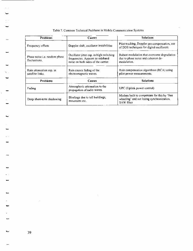
=
wTable 7. Common Technical Problems in Mobile Communication Systems
w
Problems Causes Solutions
Pilot tracking, Doppler pre-compensation, useof DDS techniques for digital oscillators.
Frequency offsets Doppler shift, oscillator instabilities
Phase noise i.e. random phase Oscillator jitter esp. in high switching Robust modulation that overcome degradationfluctuations, frequencies. Appears as sideband due to phase noise and coherent de-
noise on both sides of the carrier, modulation.
Rain attenuation esp. in Rain causes fading of the Rain compensation algorithms (RCA) usingsatellite links, electromagnetic waves, pilot power measurements.
Problems Causes Solutions
Atmospheric attenuation to the UPC (Uplink power control)Fading propagation of radio waves.
Modem built to compensate for this by 'freeBlockage due to tall buildings, wheeling' and not losing synchronization.Deep short-term shadowing mountains etc.
SAW filter
w
w
_-- 39
w
w
=
5 Market Analysis and Technological Implications for General Aviation
In-Vehicle Information Systems in the atttomotive and trucking industry and selected enablingcommunication technologies were discussed in the previous sections, in order to build an information
basis. This section provides a General Aviation (GA) market analysis to develop an understanding of theGA market and its parallels with the A/T industry in terms of on-board information systems. With thisgoal, GA market needs were investigated by means of a survey conducted at the AirVenture 2000Experimental Aircraft Association (EAA) Convention in Oshkosh, Wisconsin. Results of this survey areanalyzed in this chapter, in order to determine initial market analysis of weather information systems inGeneral Aviation (GA).
The history of GPS market acceptance provides an example of market trends for products similar tocockpit weather systems. As a result, this section also analyzes findings on GPS market acceptancehistory to characterize the GA market technology penetration patterns. Using weather informationproducts recently introduced to the aviation market and discussions with the A/T industry and the GAmarket research, possible technological implications of the on-board information systems used inautomobile and trucking industry for GA cockpit systems are discussed. This analysis begins with theOshkosh survey.
5.1 Oshkosh Survey Analysis
Information from the Oshkosh survey and data describing GPS market acceptance in the aviation andcar navigation segments can be used to characterize new technology penetration patterns in the GAmarket. This section focuses on the survey that was conducted at the AirVenture 2000 ExperimentalAircraft Association (EAA) Convention in Oshkosh, Wisconsin, from July 26 to August 1, 2000. TheEAA is an organization whose members have a wide range of aviation interests and backgrounds. Amongits members, there are a large number of pilots (from recreational to commercial), who fly a wide range ofdifferent aircraft. Survey questionnaires were taken to the convention and pres_ :ed to pilots only, to be
filled out. There were 139 total participants, with 6 recreational, 58 private, i4 instrument rated, 28commercial, and 12 air transport pilots. The remaining 21 did not specify a particular pilot category.
The survey questions were selected based on current research on existing weather informationsystems in the GA market and addressed possible information system developments identified duringadditional research on parallel technologies used in the automotive and trucking industry.
The survey consisted of five main sections with several sub elements in each. These sectionsrequested data about existing weather information systems that participants currently have, difficulties inusing current systems, desired weather information update frequencies, features participants would like tohave in the future, and costs that they are willing to pay to have these future systems. Most of the optionsrequire the use of a 1 - 5 scale to determine the level of preference or importance, 1 being least preferredor important, 5 being most preferred or important. The results of the main sections of the survey aresummarized in the following subsections. The second page is for the analysis part of this study (WeatherInformation Systems for GA Pilots), while the first page is related to another project about TAMDAR
(Tropospheric Airborne Meteorological Data Reports).
40
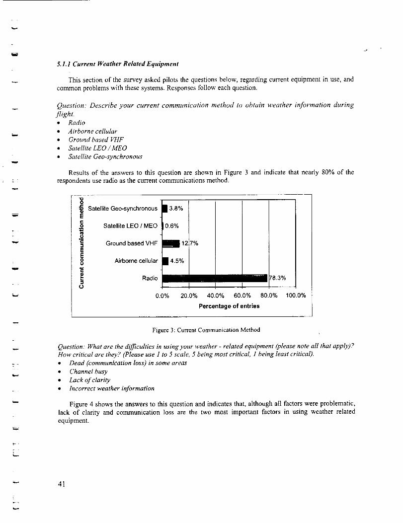
r--__°n
w
= :
w
w
5. I.I Current Weather Related Equipment
This section of the survey asked pilots the questions below, regarding current equipment in use, and
common problems with these systems. Responses follow each question.
Question. Describe your current communication method to obtain weather information during
flight.* Radio
• Airborne celhdar
• Ground based VHF
• Satellite LEO/MEO
• Satellite Geo-synchronous
Results of the answers to this question are shown in Figure 3 and indicate that nearly 80% of the
respondents use radio as the current communications method.
"1oo
Satellite Geo-synchronousEc-o Satellite LEO / MEO
,_" Ground based VHFEEo Airborne cellularu
,._ Radio,,,,i
U
13.8%
0.6%
1127%
14.5%
0.0% 20.0%
/ 78.3%I
40.0% 60.0% 80.0% 100.0%
Percentage of entries
w
w
Figure 3: Current Communication Method
Question." What are the difficulties in using your weather - related equipment (please note all that apply)?
How critical are they? (Please use 1 to 5 scale, 5 being most critical, 1 being least critical).
• Dead (communication loss) in some areas
• Channel busy
• Lack of clarity
• Incorrect weather information
Figure 4 shows the answers to this question and indicates that, although all factors were problematic,
lack of clarity and communication loss are the two most important factors in using weather related
equipment.
-" 41
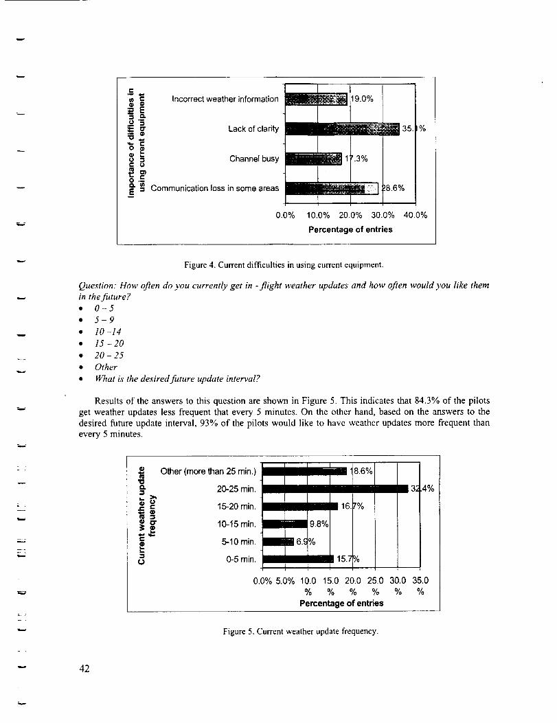
w
.E
o
=oo=
Incorrect weather information
Lack of clarity
t19.0'/oI
ii[1 35.,%
Channel busy _ 1 '.3%
Communication loss in some areas BRim|_ _.,]:.)8.6%1
0.0% 10.0% 20.0% 30.0% 40.0%
Percentage of entries
L
w
Figure 4. Current difficulties in using current equipment.
Question: How often do you currently get in -flight weather updates and how often would you like them
in the fitture?• 0-5
• 5-9
• 10 -14
• 15-20
• 20- 25
• Other
• What is the desired future update interval?
Results of the answers to this question are shown in Figure 5. This indicates that 84.3% of the pilots
get weather updates less frequent that every 5 minutes. On the other hand, based on the answers to the
desired future update interval, 93% of the pilots would like to have weather updates more frequent thanevery 5 minutes.
Other (more than 25 rain.) t 18.6%
20-25 min.
o= 15-20 min. ibm 16._'%
_i 10-15 min. 89.8%
_ 5-10 min. [] 6.c%L,-1o 0-5 min. i_l115.7 Y0
1
0.0% 5.0% 10.0 15.0 20.0 25.0
% % % %
Percentage of entries
3; 4%
i
30.0 35.0
% %
Figure 5. Current weather update frequency.
42
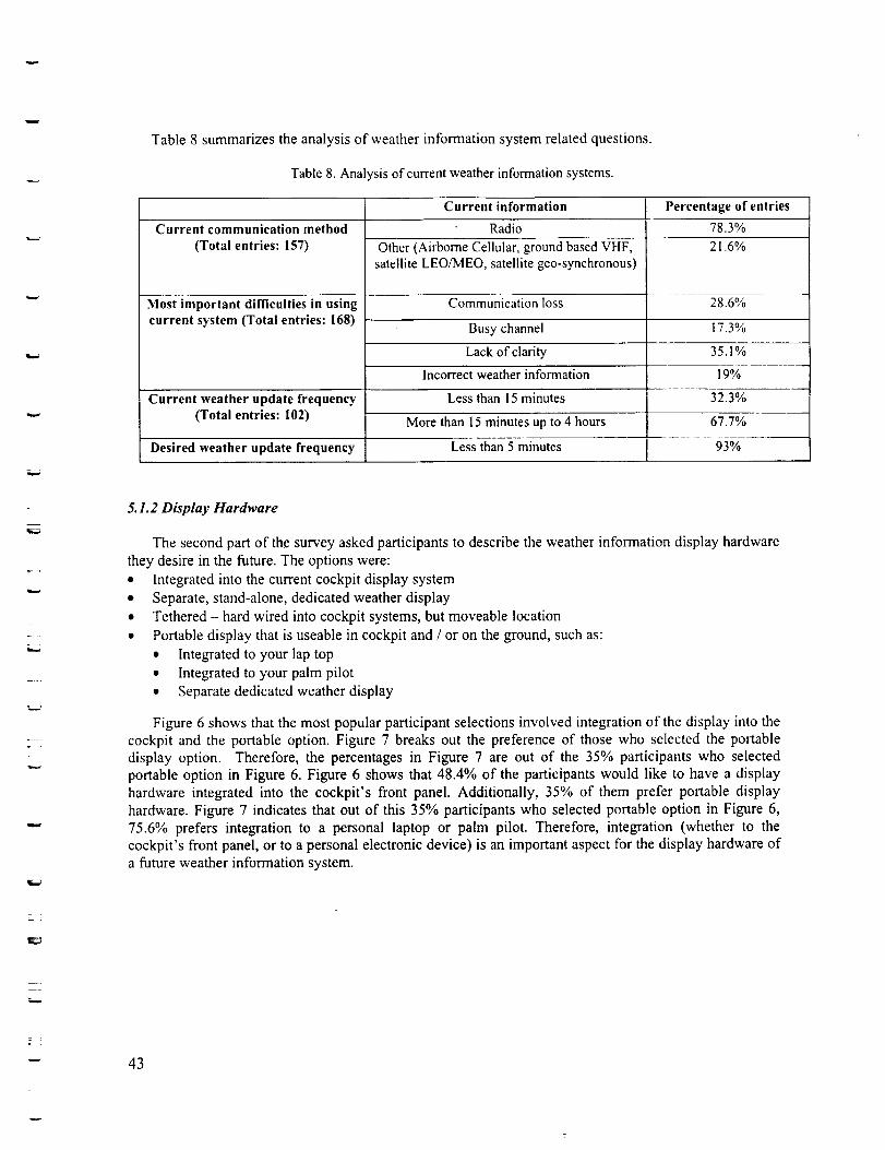
Table 8 summarizes the analysis of weather information system related questions.
Table 8. Analysis of current weather information systems.
Current communication method
(Total entries: 157)
Most important difficulties in usingcurrent system (Total entries: 168)
Current weather update frequency(Total entries: 102)
Current information
Radio
Other (Airborne Cellular, ground based VHF,satellite LEO/MEO, satellite geo-synchronous)
Communicationloss
Busy channel
Percentage of entries
78.3%
21.6%
28.6%
17.3%
Lack of clarity 35.1%
Incorrect weather information 19%
Less than 15 minutes
More than 15 minutes up to 4 hours
Desired weather update frequency Less than 5 minutes
32.3%
67.7%
93%
r
_¢&.i
5.1.2 Display Hardware
The second part of the survey asked participants to describe the weather information display hardware
they desire in the future. The options were:
• Integrated into the current cockpit display system
• Separate, stand-alone, dedicated weather display
• Tethered- hard wired into cockpit systems, but moveable location
• Portable display that is useable in cockpit and / or on the ground, such as:
• Integrated to your lap top
• Integrated to your palm pilot
• Separate dedicated weather display
Figure 6 shows that the most popular participant selections involved integration of the display into the
cockpit and the portable option. Figure 7 breaks out the preference of those who selected the portable
display option. Therefore, the percentages in Figure 7 are out of the 35% participants who selected
portable option in Figure 6. Figure 6 shows that 48.4% of the participants would like to have a display
hardware integrated into the cockpit's front panel. Additionally, 35% of them prefer portable display
hardware. Figure 7 indicates that out of this 35°/0 participants who selected portable option in Figure 6,
75.6°/0 prefers integration to a personal laptop or palm pilot. Therefore, integration (whether to the
cockpit's front panel, or to a personal electronic device) is an important aspect for the display hardware of
a future weather information system.
J
--- 43
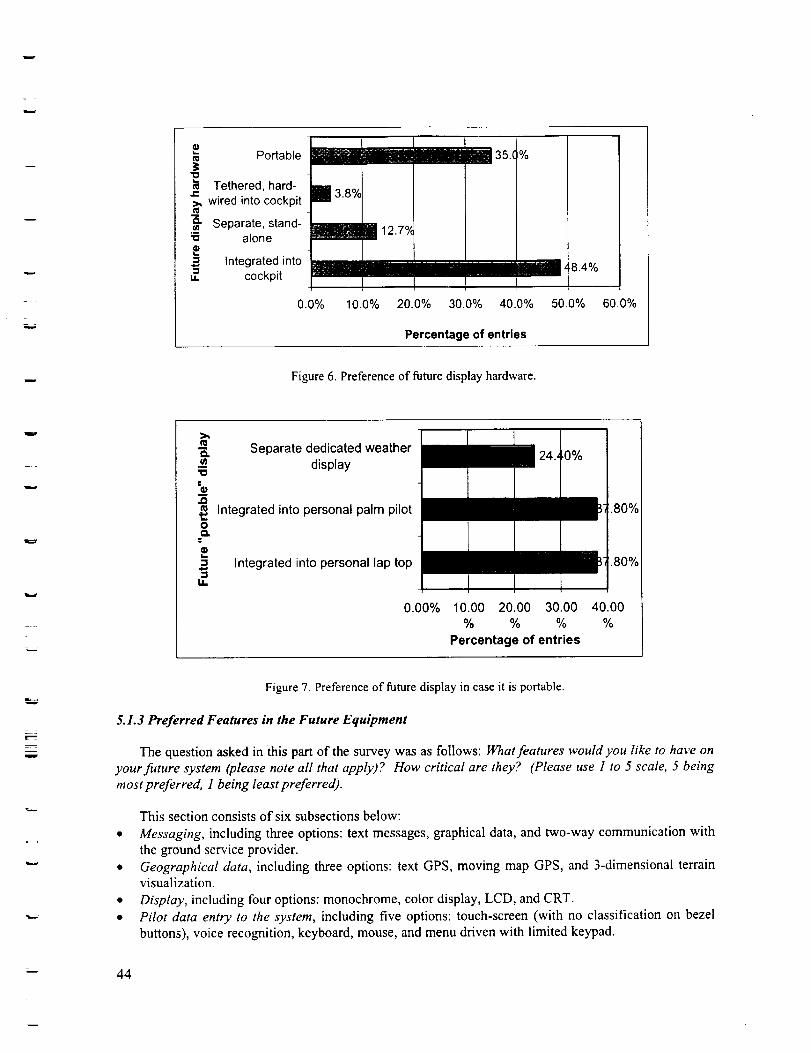
Portable __11111135.(
"oTethered, hard- iJ_ 3.8oh
_, wired into cockpit mt_
Separate, stand-_3 alone _ _ 12.7%
Integrated into• mum,, cockpit
%
0.0% 10.0% 20.0% 30.0% 40.0%
_8.4%
50.0% 60.0%
Percentage of entries
Figure 6. Preference of future display hardware.
w
t_
"og
O
g
,,,I
i,
Separate dedicated weather
display
Integrated into personal palm pilot
Integrated into personal lap top
0.00%
1 24., _0%
.80%
.8O%
i
10.00 20.00 30.00 40.00
% % % %
Percentage of entries
w
= =
= .
Figure 7. Preference of future display in case it is portable.
5.1.3 Preferred Features in the Future Equipment
The question asked in this part of the survey was as follows: What features wouldyou like to have on
your future system (please note all that apply)? How critical are they? (Please use 1 to 5 scale, 5 being
most preferred, 1 being least preferred).
This section consists of six subsections below:
• Messaging, including three options: text messages, graphical data, and two-way communication with
the ground service provider.
• Geographical data, including three options: text GPS, moving map GPS, and 3-dimensional terrainvisualization.
• Display, including four options: monochrome, color display, LCD, and CRT.
• Pilot data entry to the system, including five options: touch-screen (with no classification on bezel
buttons), voice recognition, keyboard, mouse, and menu driven with limited keypad.
44
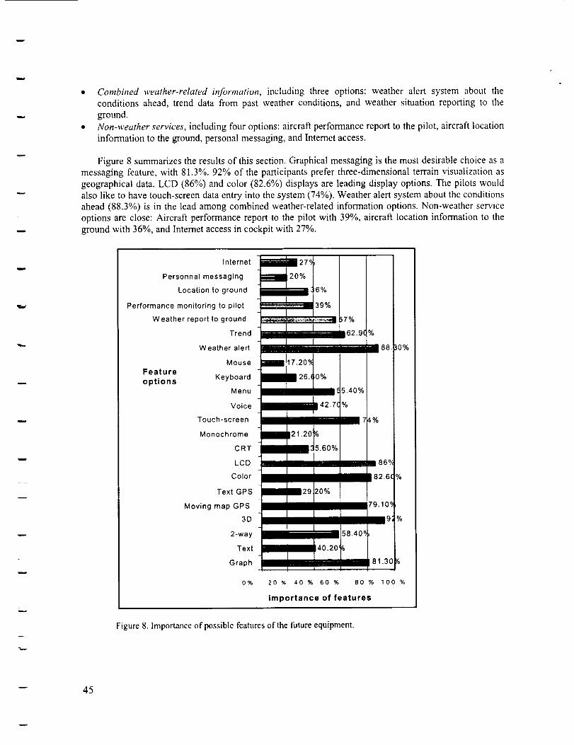
• Combined weather-related information, including three options: weather alert system about the
conditions ahead, trend data from past weather conditions, and weather situation reporting to the
ground.
• Non-weather services, including four options: aircraft performance report to the pilot, aircraft location
information to the ground, personal messaging, and Internet access.
Figure 8 summarizes the results of this section. Graphical messaging is the most desirable choice as a
messaging feature, with 81.3%. 92% of the participants prefer three-dimensional terrain visualization as
geographical data. LCD (86%) and color (82.6%) displays are leading display options. The pilots would
also like to have touch-screen data entry into the system (74%). Weather alert system about the conditions
ahead (88.3%) is in the lead among combined weather-related information options. Non-weather service
options are close: Aircraft performance report to the pilot with 39%, aircraft location information to the
ground with 36%, and Internet access in cockpit with 27%.
n_ __:
Internet
Personnal messaging
Location to ground
Performance monitoring to pilot
Weather report to ground
Trend
Weather alert
Mouse
Feature
options Keyboard
Menu
Voice
Touch-screen
Monochrome
CRT
LCD
Color
Text GPS
Moving map GPS
3D
2-way
Text
Graph
o%
6%
---._.,=-_ _ 39%
___ ;7%
ill 62.9f %
/ 17.20°A
___55.40%
/ il 42"7C%
ii21.20_
_/" 5.6oo/0
m m29 20%
=88.
t_%
86o,,
82.6q
79.10_
9
58.405
__ 40.20'/o
81.3£
zo _ 40 % 60 % Bo %
Importance of features
Figure 8. Importance of possible features of the future equipment.
%
lOO %
-- 45
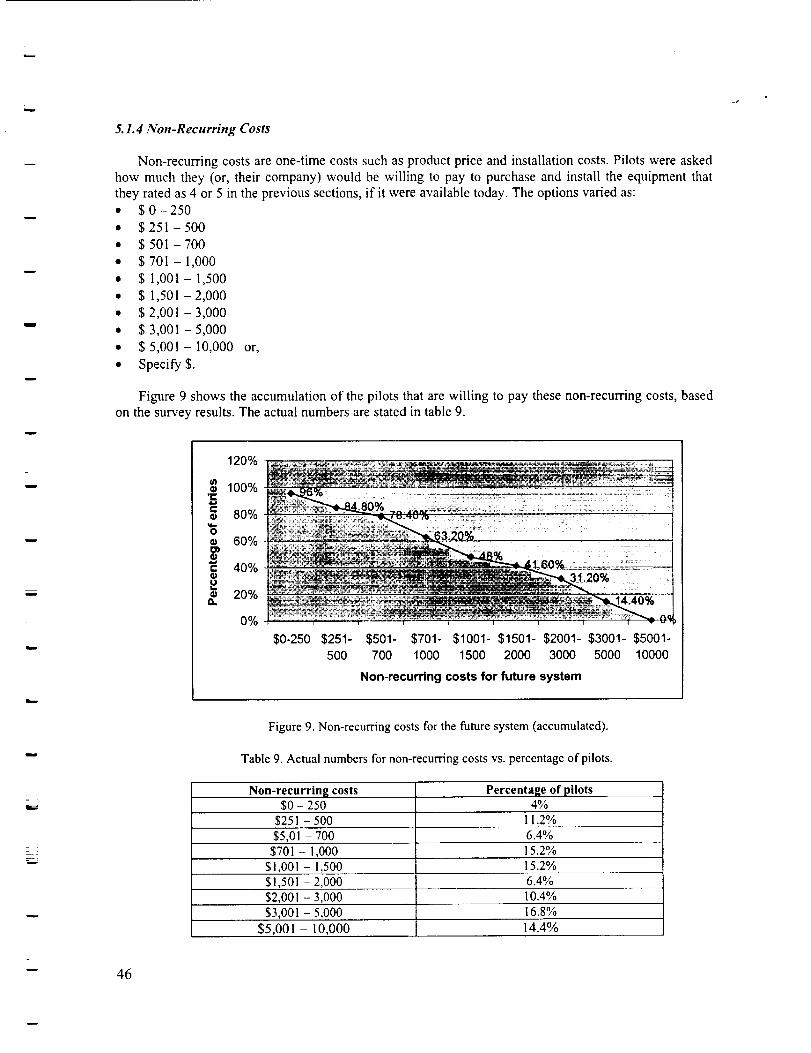
w
5.1.4 Non-Recurring Costs
Non-recurring costs are one-time costs such as product price and installation costs. Pilots were asked
how much they (or, their company) would be willing to pay to purchase and install the equipment that
they rated as 4 or 5 in the previous sections, if it were available today. The options varied as:
• $ 0- 250
• $ 251 - 500
• $ 501 - 700
• $701-1,000
• $ 1,001 - 1,500
• $ 1,501 -2,000
• $ 2,001 -3,000
• $ 3,001 -5,000
• $ 5,001 - 10,000 or,
• Specify$.
Figure 9 shows the accumulation of the pilots that are willing to pay these non-recurring costs, based
on the survey results. The actual numbers are stated in table 9.
120%
lOO%._-
g 8o%"6a_ 60%g,
40%¢1
_. 20%
0%
$0-250 $251-500
$501- $701- $1001- $1501- $2001- $3001- $5001-
700 1000 1500 2000 3000 5000 10000
Non-recurdng costs for future system
Figure 9. Non-recurring costs for the future system (accumulated).
Table 9. Actual numbers for non-recurring costs vs. percentage of pilots.
Non-recurring costs$0 - 250
Percentage of pilots4%
$251 - 500 il.2%
$5,01 - 700 6.4%$701 - 1,000 15.2%
$1,001 - 1,500 15.2%$1,501 - 2,000 6.4%
$2,001 - 3,000 10.4%$3,001 - 5,000 16.8%
$5,001 - 10,000 14.4%
-- 46
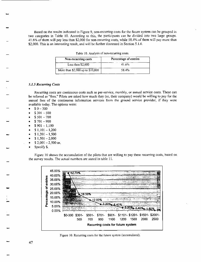
BasedontheresultsindicatedinFigure9,non-recurringcostsforthefuturesystemcanbegroupedintwo categoriesin Table10.Accordingto this,theparticipantscanbedividedintotwo largegroups.41.6%of themwill paylessthan$2,000fornon-recurringcosts,while58.4% of them will pay more than
$2,000. This is an interesting result, and will be further discussed in Section 5.1.6.
Table 10. Analysis of non-recurring costs.
Non-recurring costs Percentage of entries
Less than $2,000 41.6%
More than $2,000 up to $10,000 58.4%
w
5.1.5 Recurring Costs
Recurring costs are continuous costs such as per-service, monthly, or annual service costs. These can
be referred as "fees." Pilots are asked how much they (or, their company) would be willing to pay for the
annual fees of the continuous information services from the ground service provider, if they were
available today. The options were:
• $ 0- 300
• $ 301 - 500
• $ 501 - 700
• $ 701 -900
• $901- 1,100
• $ 1,101 - 1,200
• $ 1,201 - 1,500
• $ 1,501-2,000
• $ 2,001 - 2,500 or,
• Specify$.
Figure 10 shows the accumulation of the pilots that are willing to pay these recurring costs, based on
the survey results. The actual numbers are stated in table 11.
47
45.00°/0Ef42 o% ..... -.........t_ 40.00% _-..................... '....
• 35.ooo/030.00%
'_ 25.00%
_ 20.00%
15.00%10.00%
" 5.00%
0.00%
. •.................. =_= . ,._._.-=. 427j
$0-300 $301- $501- $701- $901- $1101- $1201- $1501- $2001-
500 700 900 1100 1200 1500 2000 2500
Recurring costs for future system
Figure 10. Recurring costs for the future system (accumulated).
Table1I.Actualnumbersforrecurringcostsvs.percentageofpilots.
Recurring costs$0 - 300
Percentage of pilots57.3%
$301 - 500 24.2%
$5,01 - 700 6.5%$701 - 900 4.8%
$901 - 1,100 0.8%
$1,101 - 1,200 3.2%
$1,201 - 1,500 0.8%$1,501 - 2,000 0.8%
$2,001 - 2,500 1.6%
Based on the results indicated in Figure 10, recurring costs for the future system can be grouped in
two categories in Table 12. Most of the pilots would not like to pay more than $500 for recurring costs.
Therefore, even if the non-recurring costs are relatively high, recurring costs should be kept low for the
future systems.
Table 12. Analysis of recurring costs.
Recurring costs Percentage of entries
Less than $500 81.5%
More than $500 up to $2,500 18.5%
i
w
5.1. 6 Survey Analysis
This section summarizes and integrates the results of the survey. According to the survey responses,
78.4% of the participant pilots use weather radio to receive weather information. The most importantdifficulties they face in using this current equipment are lack of clarity and communication loss in some
areas during flight. They currently receive weather updates less frequently than every 15 minutes, which
is not adequate since they would like to be informed about the weather conditions more frequently than
every 5 minutes. In summary, current weather information equipment, which is used by majority of the
139 participants, needs to be improved, or replaced by another system.
Survey participants identified desired characteristics of the future system. They would like to have a
system with display hardware integrated into the cockpit's front panel (48.4%), or portable (35%). If the
system is portable, they prefer it to be integrated into their personal palm pilot or laptop. This means that
the integration of the future system into other information technologies is desired. In fact, this is usuallythe case when information systems such as GPS are considered (ref. 27). Participants indicated that the
following features are most desirable, in their future system:
• Graphical messaging (81.3%)
• Three-dimensional terrain visualization (92%)
• LCD (86%) or color (82.6%) display
• Touch-screen data entry into the system (74%)
• Weather alert system about the conditions ahead (88.3°/0)
• Non-weather services are close to each other: Aircraft performance report to the pilot with 39°/0,
aircraft location information to the ground with 36%, and lnternet access in cockpit with 27%.
•- 48
!
Most participants are not willing to pay more than $500 as recurring costs, which are annual fees for
continuing services. So that, independent from the non-recurring costs, which are the costs for purchasing
and installing the equipment, recurring costs should be in this range to satisfy these customers.
Participants are divided almost evenly in terms of non-recurring costs as indicated in table 9. 58.4%
of them are willing to pay more than $2,000 up to $10,000, while 41.6% would like to have a product for
less than $2,000. To further analyze this result, the participant responses were broken down into
professional categories since professional affiliation might be an important parameter that affects
preference of non-recurring costs. In Table 11, a breakdown of non-recurring costs is shown with respect
to pilots' professions. It indicates that most of the private, instrument rated and commercial pilots are not
willing to pay more than $2,000 for purchasing and installing the future system. Among these,commercial pilots are the ones who make a relatively larger contribution to the higher price range. This is
reasonable since private and instrument rated pilots are usually not profit based, but personal interest
oriented, while commercial pilots are more for-profit based. Recreational pilot data does not add value to
the analysis since they divide evenly between the two price ranges. Air transport pilots who are usually
airline pilots are willing to pay more than $2,000. This is probably due to their high disposable income
level, or their companies' affordability.
Table I I. Non-recurring costs that pilots are willing to pay (Breakdown with respect to profession).
Pilot Professions Less than $2,00072%Private Pilots
Instrument Rated Pilots 71% 29%
Commercial Pilots 61% 39%
Air Transport Pilots 33% 67%Recreational Pilots 50% 50%
More than $2_000 up to $10700028%
m
5.2 GPS Market Acceptance
In characterizing the steps of GA market acceptance in this research, GPS was considered a good
candidate to study as an example of information technology penetration. Based on this information, it is
possible to estimate the market growth patterns for future information system products, such as weather
information systems.
While considering technology transfer from the automotive and trucking industry to GA in terms ofon-board weather information systems, basic similarities between these technologies and GPS are
realized. For example, GPS is another information technology that is used both in automotive and
trucking and aviation industries. It is an example of the same technology application to both public needs
and commercial enterprise. Especially in the aviation market, improving safety is one of the main
purposes of using GPS, even more important than price (ref. 28).
This section covers the market acceptance history of GPS from its first introduction to civil use
(1993) to year 2000. The data presented in the following chapters are taken from a U.S. Department of
Commerce Report submitted on September 1998 (ref. 28). This report includes detailed information on
worldwide GPS sales and market projections for market segments such as car navigation, aviation,
marine, military, consumer, tracking/machine control, OEM, and survey/mapping/GIS. In this study, only
GPS worldwide sales data in car navigation and aviation segments are considered, in order to identify
possible similarities between them, and to have a closer look at the aviation market.
49
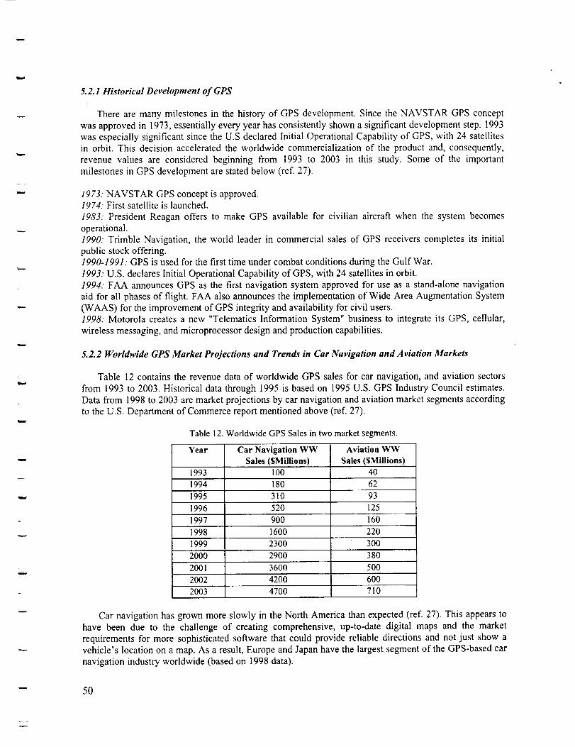
w
w
r
=
w
5.2.1 Historical Development of GPS
There are many milestones in the history of GPS development. Since the NAVSTAR GPS concept
was approved in 1973, essentially every year has consistently shown a significant development step. 1993
was especially significant since the U.S declared Initial Operational Capability of GPS, with 24 satellites
in orbit. This decision accelerated the worldwide commercialization of the product and, consequently,
revenue values are considered beginning from 1993 to 2003 in this study. Some of the important
milestones in GPS development are stated below (ref. 27).
1973: NAVSTAR GPS concept1974. First satellite is launched.
1983: President Reagan offers
operational.
1990: Trimble Navigation, the
public stock offering.
is approved.
to make GPS available for civilian aircraft when the system becomes
world leader in commercial sales of GPS receivers completes its initial
1990-1991: GPS is used for the first time under combat conditions during the Gulf War.
1993: U.S. declares Initial Operational Capability of GPS, with 24 satellites in orbit.
1994: FAA announces GPS as the first navigation system approved for use as a stand-alone navigation
aid for all phases of flight. FAA also announces the implementation of Wide Area Augmentation System
(WAAS) for the improvement of GPS integrity and availability for civil users.
1998: Motorola creates a new "Telematics Information System" business to integrate its GPS, cellular,
wireless messaging, and microprocessor design and production capabilities.
5.2.2 Worldwide GPS Market Projections and Trends in Car Navigation and Aviation Markets
Table 12 contains the revenue data of worldwide GPS sales for car navigation, and aviation sectors
from 1993 to 2003. Historical data through 1995 is based on 1995 U.S. GPS Industry Council estimates.
Data from 1998 to 2003 are market projections by car navigation and aviation market segments according
to the U.S. Department of Commerce report mentioned above (ref. 27).
Table 12. Worldwide GPS Sales in two market segments.
Year Car Navigation WW Aviation WW
Sales($Millions) Sales($Millions)1993 100 40
1994 180 62
1995 310 93
1996 520 125
1997 900 160
1998 1600 220
1999 230O 300
2000 2900 380
2001 3600 500
2002 4200 600
2003 4700 710
Car navigation has grown more slowly in the North America than expected (ref. 27). This appears to
have been due to the challenge of creating comprehensive, up-to-date digital maps and the market
requirements for more sophisticated software that could provide reliable directions and not just show a
vehicle's location on a map. As a result, Europe and Japan have the largest segment of the GPS-based car
navigation industry worldwide (based on 1998 data).
5O
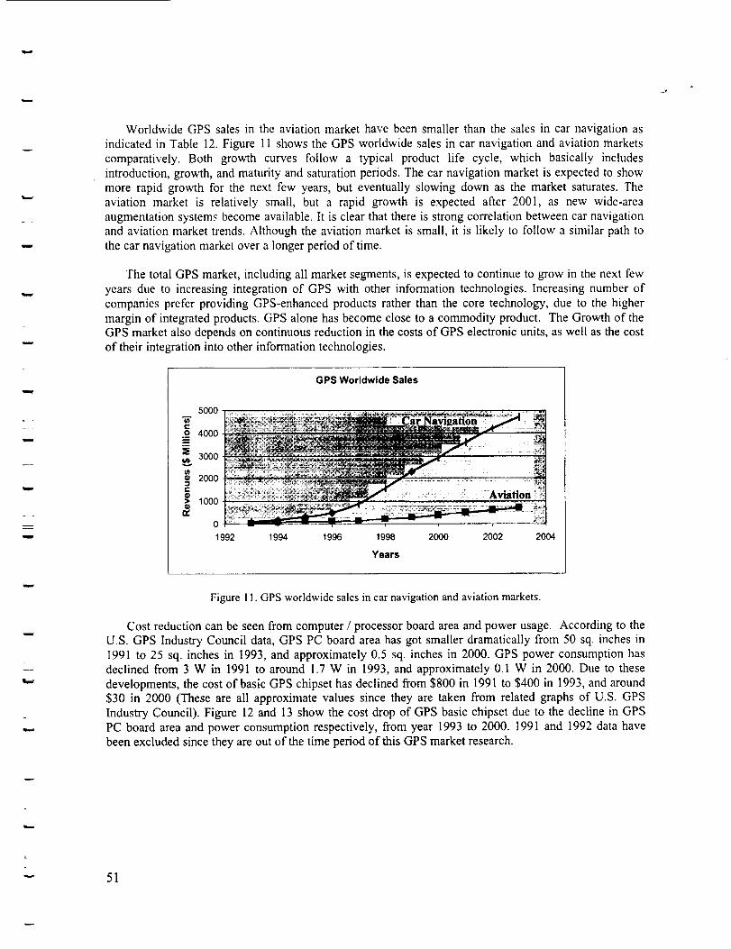
w
=
w
w
Worldwide GPS sales in the aviation market have been smaller than the sales in car navigation as
indicated in Table 12. Figure 11 shows the GPS worldwide sales in car navigation and aviation marketscomparatively. Both growth curves follow a typical product life cycle, which basically includesintroduction, growth, and maturity and saturation periods. The car navigation market is expected to showmore rapid growth for the next few years, but eventually slowing down as the market saturates. The
aviation market is relatively small, but a rapid growth is expected after 2001, as new wide-areaaugmentation systems become available. It is clear that there is strong correlation between car navigationand aviation market trends. Although the aviation market is small, it is likely to follow a similar path tothe car navigation market over a longer period of time.
The total GPS market, including all market segments, is expected to continue to grow in the next fewyears due to increasing integration of GPS with other information technologies. Increasing number ofcompanies prefer providing GPS-enhanced products rather than the core technology, due to the higher
margin of integrated products. GPS alone has become close to a commodity product. The Growth of theGPS market also depends on continuous reduction in the costs of GPS electronic units, as well as the costof their integration into other information technologies.
GPS Worldwide Sales
5OO0
e,.
._o 4000
3000
2oo0C
1000Q_
n,
o
1992 1994 1996 1998 2000 2002 2004
Years
= •
Figure 1 I. GPS worldwide sales in car navigation and aviation markets.
Cost reduction can be seen from computer / processor board area and power usage. According to theU.S. GPS Industry Council data, GPS PC board area has got smaller dramatically from 50 sq. inches in1991 to 25 sq. inches in 1993, and approximately 0.5 sq. inches in 2000. GPS power consumption hasdeclined from 3 W in 1991 to around 1.7 W in 1993, and approximately 0.I W in 2000. Due to these
developments, the cost of basic GPS chipset has declined from $800 in 1991 to $400 in 1993, and around$30 in 2000 (These are all approximate values since they are taken from related graphs of U.S. GPS
Industry Council). Figure 12 and 13 show the cost drop of GPS basic chipset due to the decline in GPSPC board area and power consumption respectively, from year 1993 to 2000. 1991 and 1992 data havebeen excluded since they are out of the time period of this GPS market research.
v 51
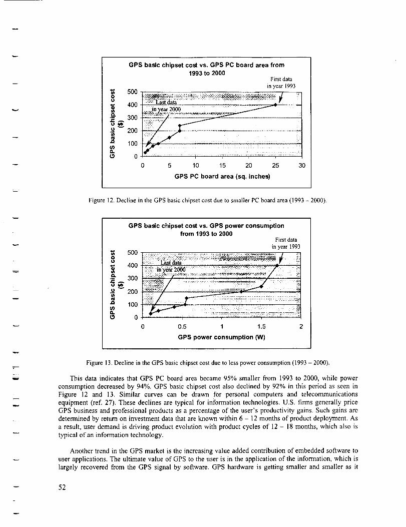
GPS basic chipset cost vs. GPS PC board area from1993 to 2000
First data
in year [993"_ 5000
400U)0.
Z _ 300v
•_ 200U')
100a,.
0
0 5 10 15 20 25 30
GPS PC board area (sq. Inches)
Figure 12. Decline in the GPS basic chipset cost due to smaller PC board area (1993 - 2000).
1
w
GPS basic chipset cost vs. GPS power consumptionfrom 1993 to 2000
First data
in year 1993"_ 5O0O0
•,_ 400i/}
o 200
'_ 100
a.
C9 0
0 0.5 1 1.5 2
GPS power consumption ON)
Figure 13. Decline in the GPS basic chipset cost due to less power consumption (1993 - 2000).
This data indicates that GPS PC board area became 95% smaller from 1993 to 2000, while power
consumption decreased by 94%. GPS basic chipset cost also declined by 92% in this period as seen in
Figure 12 and 13. Similar curves can be drawn for personal computers and telecommunications
equipment (ref. 27). These declines are typical for information technologies. U.S. firms generally price
GPS business and professional products as a percentage of the user's productivity gains. Such gains are
determined by return on investment data that are known within 6 - 12 months of product deployment. As
a result, user demand is driving product evolution with product cycles of 12 - 18 months, which also is
typical of an information technology.
Another trend in the GPS market is the increasing value added contribution of embedded software to
user applications. The ultimate value of GPS to the user is in the application of the information, which is
largely recovered from the GPS signal by software. GPS hardware is getting smaller and smaller as it
-- 52
=
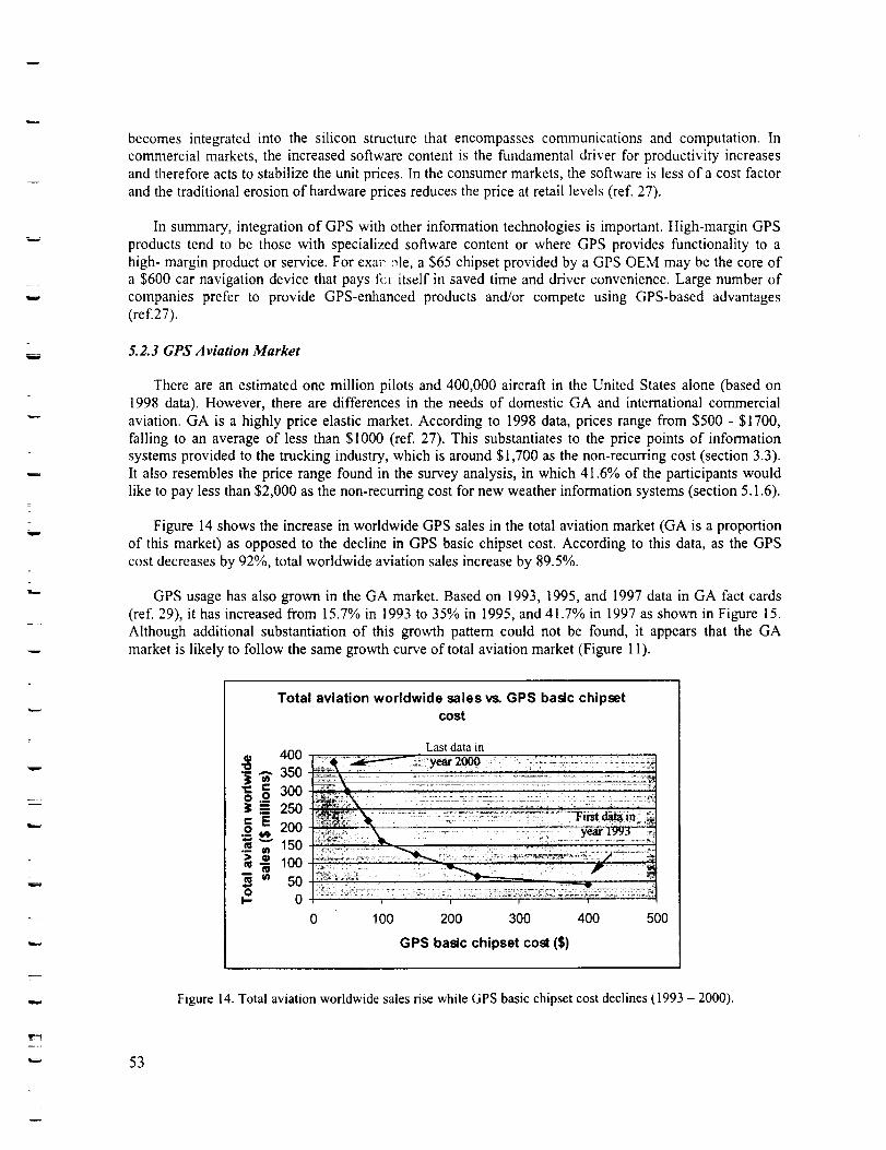
zzW
w
becomes integrated into the silicon structure that encompasses communications and computation. In
commercial markets, the increased software content is the fundamental driver for productivity increases
and therefore acts to stabilize the unit prices. In the consumer markets, the software is less of a cost factor
and the traditional erosion of hardware prices reduces the price at retail levels (ref. 27).
In summary, integration of GPS with other information technologies is important. High-margin GPS
products tend to be those with specialized software content or where GPS provides functionality to a
high- margin product or service. For exam: :_le, a $65 chipset provided by a GPS OEM may be the core ofa $600 car navigation device that pays t\:r itself in saved time and driver convenience. Large number of
companies prefer to provide GPS-enhanced products and/or compete using GPS-based advantages(ref.27).
5.2.3 GPS Aviation Market
There are an estimated one million pilots and 400,000 aircraft in the United States alone (based on
1998 data). However, there are differences in the needs of domestic GA and international commercial
aviation. GA is a highly price elastic market. According to 1998 data, prices range from $500 - $1700,
falling to an average of less than $I000 (ref. 27). This substantiates to the price points of information
systems provided to the trucking industry, which is around $1,700 as the non-recurring cost (section 3.3).
It also resembles the price range found in the survey analysis, in which 41.6% of the participants would
like to pay less than $2,000 as the non-recurring cost for new weather information systems (section 5.1.6).
Figure 14 shows the increase in worldwide GPS sales in the total aviation market (GA is a proportion
of this market) as opposed to the decline in GPS basic chipset cost. According to this data, as the GPS
cost decreases by 92%, total worldwide aviation sales increase by 89.5%.
GPS usage has also grown in the GA market. Based on 1993, 1995, and 1997 data in GA fact cards
(ref. 29), it has increased from 15.7% in 1993 to 35% in 1995, and 41.7% in 1997 as shown in Figure 15.
Although additional substantiation of this growth pattern could not be found, it appears that the GA
market is likely to follow the same growth curve of total aviation market (Figure 11).
w
w
53
Total aviation worldwide sales vs. GPS basic chipsetcost
• 400"_ 350
300
_ 250
20015o
"_ 1O0
50oI- 0
0 100
Last datainyear2000
200 300 400 500
GPS basic chipset cost ($)
Figure 14. Total aviation worldwide sales rise while GPS basic chipset cost declines (1993 - 2000).
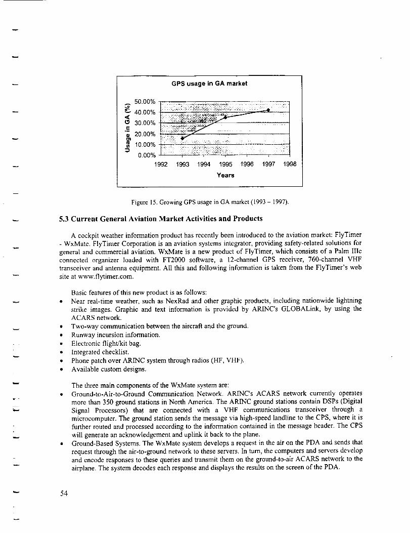
GPS usage in GA market
50.00%
_ 40.00%<(3c
.m
o_
30.00%
20.00%
10.00%
0.00%
1992
m
• i .................
t I ....... I l
1993 1994 1995 1996 1997 1998
Years
w
Figure 15. Growing GPS usage in GA market (1993 - 1997).
5.3 Current General Aviation Market Activities and Products
A cockpit weather information product has recently been introduced to the aviation market: FlyTimer
- WxMate. FlyTimer Corporation is an aviation systems integrator, providing safety-related solutions for
general and commercial aviation. WxMate is a new product of FlyTimer, which consists of a Palm IIIc
connected organizer loaded with FT2000 software, a 12-channel GPS receiver, 760-channel VHF
transceiver and antenna equipment. All this and following information is taken from the FlyTimer's web
site at www.flytimer.com.
Basic features of this new product is as follows:
• Near real-time weather, such as NexRad and other graphic products, including nationwide lightning
strike images. Graphic and text information is provided by ARINC's GLOBALink, by using theACARS network.
• Two-way communication between the aircraft and the ground.
• Runway incursion information.
• Electronic flight/kit bag.
• Integrated checklist.
• Phone patch over ARINC system through radios (HF, VHF).
• Available custom designs.
The three main components of the WxMate system are:
• Ground-to-Air-to-Ground Communication Network. ARINC's ACARS network currently operates
more than 350 ground stations in North America. The ARINC ground stations contain DSPs (Digital
Signal Processors) tha.t are connected with a VHF communications transceiver through a
microcomputer. The ground station sends the message via high-speed landline to the CPS, where it is
further routed and processed according to the information contained in the message header. The CPS
will generate an acknowledgement and uplink it back to the plane.
• Ground-Based Systems. The WxMate system develops a request in the air on the PDA and sends that
request through the air-to-ground network to these servers. In turn, the computers and servers develop
and encode responses to these queries and transmit them on the ground-to-air ACARS network to the
airplane. The system decodes each response and displays the results on the screen of the PDA.
" 54
w
L
Aircraft-Based Components. The WxMate system has three major components in each airplane,which are transceiver, antennas and CDU (Computerized Display Unit). It also contains an FCCcertified 760-channel VHF radio module. This module is somewhat transparent to the user as the
PDA with its embedded software is the primary user interface. The system also includes a DSPmicroprocessor.
The WxMate system is expected to cost between $2800 and $6000, depending on systemconfiguration. Text messages are expected to be without any charge, but data will be on subscription basisand will cost most pilots about $45 per month (according to an interview with the system provider). Thisproduct is currently in final certification testing.
Some of the other cockpit weather service providers are: ViGYAN, Capstone, AVIDYNE, EchoFlight, and ARNAV. ViGYAN is seeking capital to bring its pilot Weather Advisor (PWA) system tomarket. This system delivers near real time weather information to airplanes using a satellite broadcast
and graphically displays the information to pilots (ref. 30). Capstone is exploring a digitally poweredglass display on the instrument panel, which gives the pilot a variety of information in one place and hasdifferent capabilities depending on how it is configured. Navigation maps, terrain information, weatherinformation, and aircraft targets are presented on the moving map-equipped display. The UniversalAccess Transceiver (UAT) is the two-way digital data link employed in this system (ref. 31).AVIDYNE's FlightMax displays integrate GPS navigation information, traffic information, lightninginformation (from Stormscope), and terrain on a single display (ref. 32). Echo Flight's Flight Cheetah FL270 is a portable device, which provides GPS navigation, graphical weather, terrain alert, messaging, andairport information. Weather information is provided by request/reply via satellite transmission (ref. 33).ARNAV has developed a graphical cockpit display of weather information using a low-cost datalink for
ground-to-cockpit transmission for GA. It provides e-mail messaging from the cockpit. GPS navigation,graphical display on cockpit management systems, and wireless datalink communications technologyhave formed the hardware basis for the "Weather in the Cockpit System (ref. 34)."
5.4 Technological Implications of Automobile and Trucking Information Systems forGeneral Aviation
This chapter identified a number of advanced wireless and device technologies that will enable thegrowth of mobile information systems in the A/T sector and that have possible applications in the generalaviation sector. Section 4 discussed others including display and voice recognition technologies, softwareapplications and satellite and terrestrial networks that deliver broadband data services. These areexamples of technologies, which may have implications for the airborne mobile device user.
Although aviation is one step ahead in the system architecture definition as compared to the terrestrialITS program, there are a number of technologies and products that can be considered to be common to therequirements of the A/T industry, as well as the aviation arena. Developments in wireless communicationtechnology are constantly enabling more feature-rich, cheaper, lighter and power efficient wireless and
portable terminals. For example, various methods are being developed for driving bit error rates down andincreasing performance (multi user detection for interference rejection, advanced coding schemes such asturbo codes, adaptive antennas which contribute to more efficient utilization of the frequency bands, etc.).
The cellular handset, which is far more sophisticated than a wireline handset, incorporates powerful,high-speed microprocessors and DSPs. It is also rapidly shrinking in its form factor while havingadvanced capabilities such as voice recognition, and handwriting input. This has been made possible byminiaturization, and developments in semiconductor technology and ASIC (Application Specific
Integrated Circuit) design.
55
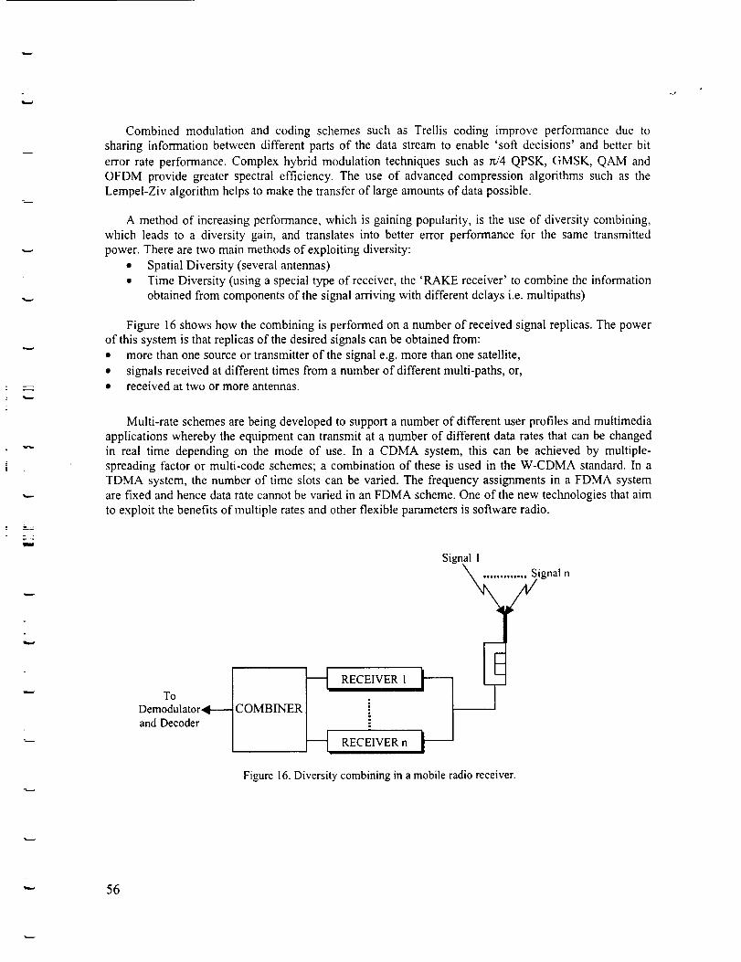
L
Combined modulation and coding schemes such as Trellis coding improve performance due tosharing information between different parts of the data stream to enable 'soft decisions' and better bit
error rate performance. Complex hybrid modulation techniques such as W4 QPSK, GMSK, QAM andOFDM provide greater spectral efficiency. The use of advanced compression algorithms such as theLempel-Ziv algorithm helps to make the transfer of large amounts of data possible.
A method of increasing performance, which is gaining popularity, is the use of diversity combining,which leads to a diversity gain, and translates into better error performance for the same transmitted
power. There are two main methods of exploiting diversity:• Spatial Diversity (several antennas)
• Time Diversity (using a special type of receiver, the 'RAKE receiver' to combine the informationobtained from components of the signal arriving with different delays i.e. multipaths)
Figure 16 shows how the combining is performed on a number of received signal replicas. The powerof this system is that replicas of the desired signals can be obtained from:
• more than one source or transmitter of the signal e.g. more than one satellite,
• signals received at different times from a number of different multi-paths, or,• received at two or more antennas.
Multi-rate schemes are being developed to support a number of different user profiles and multimediaapplications whereby the equipment can transmit at a number of different data rates that can be changedin real time depending on the mode of use. In a CDMA system, this can be achieved by multiple-spreading factor or multi-code schemes; a combination of these is used in the W-CDMA standard. In aTDMA system, the number of time slots can be varied. The frequency assignments in a FDMA systemare fixed and hence data rate cannot be varied in an FDMA scheme. One of the new technologies that aim
to exploit the benefits of multiple rates and other flexible parameters is software radio.
RECEIVER 1
RECEIVER n t--
Signal Iignal n
Figure 16. Diversity combining in a mobile radio receiver.
"" 56
5.4. I Software Radios
Software radios are developed to address functionalities that are critical to the successful
implementation of future mobile communication standards. Software radios are characterized by over-
the-air change of communication scheme/protocol (e.g. support for both W-CDMA and GSM on one
device). It facilitates the use of sophisticated terminals that are network aware and re-configurable. This
issue will be more important in the future, considering the heterogeneity of network platforms and
terminals that will co-exist. Application Protocol Interface (API) is capable of delivering a service, which
the underlying network and the terminal can support, to the user. Development of this interface is a key
issue, especially when roaming from a bandwidth rich environment such as a terrestrial network towards abandwidth limited satellite network.
Software radio implementation involves two key concepts: channelization and sample rate adaptation.
This is achieved by the use of a re-configurable architecture consisting of FPGAs (Field Programmable
Gate Arrays) and high-speed Digital Signal Processors (DSPs). In software radios the digitization of the
whole channel bandwidth is done at IF frequencies. This puts a huge processing burden on the Analog-
to-Digital Converters (ADC's) and the signal processing components. The technology associated with
these sophisticated terminals is a topic for current investigation.
m
-- 57
hw
6 Conclusions and Recommendations
This study identified current on-board information systems used in the A/T industry, and determinedtheir key characteristics. It provided a background to work on possible implications for new technologypenetration in the GA industry.
According to historical development of such technologies worldwide, ITS programs are launched as aresult of traffic problems such as urban congestion, increased cost from time devoted to traveling,accidents, rising road deaths, safety, security, and environmental pollution. Driver errors are one of theprimary causes of accidents, and new on-board transportation systems including integration of electronics,computers and telecommunications are expected to reduce these problems. These studies are conductedby the cooperation of public and private sectors. The public sector usually initiates, supports, and leadsthe ITS studies while the private sector contributes to the funding, R&D projects, and applications.General objectives of using on-board information systems are: providing on-board route guidance andnavigation, fleet management, traffic and travel information (such as road works, parking, location ofmajor facilities, emergency information of weather conditions, pollution monitoring and advisorysystems) through various communication systems (such as cellular phones, and in-vehicle computers),and facilitating the development of driver assistance safety products. The use of on-board information
systems is rising dramatically worldwide, due to increasing number of users preferring vehicles equippedwith these systems.
In the trucking industry, the communication method is generally either satellite, cellular, or radio.There are also separate or integrated GPS systems on-board. Text messages are most common forcommunication between the driver and the dispatcher. Displays are usually either separate, or integratedinto the front panel or a laptop. Data entry is done by using either a touch screen display, voice by cellphone, or a keyboard. There are many services provided to the trucking industry such as maintenance andperformance monitoring to the driver, emergency alert, automatic location information to the dispatcher,configurable business forms and templates, optional printer, fax, pager, special function buttons, black
box, etc. Information system providers in the trucking industry are considering the followingdevelopments on their products in the future: Interact access on-board, traffic information servicesintegrated with route optimization, increased capacity and baud rates, and voice recognition forcommunication.
In the automotive industry, the communication method is usually cellular based. Communication isoften provided by either text, or voice messages (by cell phone), or both, primarily by communicatingwith an assistance center, which provides most of the information that the driver needs. For navigation,integrated or separate GPS devices are provided. Data entry to the system is usually by using specialfunction buttons. System services can be grouped as maintenance and performance monitoring such asautomatic airbag deployment notification to the assistance center, roadside assistance such as trafficupdates and weather information to the driver, and other services such as stolen vehicle tracking, andsatellite radio subscriptions. Future developments will include more voice recognition for hands-freecommunication, more integrated systems into the front panel, advanced Internet access, and moreinformation about the traffic and weather conditions ahead.
Based on this market search, it can be concluded that the driver in the trucking industry is more like a
pilot who communicates with the dispatcher frequently, and the truck is like an aircraft that is beingtracked by the dispatcher at certain time intervals. The dispatcher has a relatively similar role to groundstations in aviation. In one of the trucking systems, even a black box is provided in case an accidentoccurs. This parallel is due to the fact that the information systems are used for business purposes, and formanaging a fleet of trucks that travel to different destinations in this market. Driver and truck safety is
-- 58
w
L
important, and monitored by deployment of features such as maintenance and performance monitoring tothe driver, and automatic emergency alert signal to the dispatcher.
On the other hand, the automotive industry is more concerned about the convenience of the user.
Automotive companies provide on-board services such as satellite radio subscriptions, and personal websites for the driver. There are tracking services in this area as well, but it is usually occasional such asstolen vehicle tracking. Driver safety is also important so that there is emergency signal service to theassistance center as well. In both markets (automotive and trucking) however, similar developments arebeing considered. The driver in a truck will be able to use Internet for business communications, but forpersonal messaging as well. In both markets, advanced Internet services are desired. For communication,voice recognition is the most popular technology for its convenience, and probably due to the demand forhands-free communication (in some U.S. states, using cell phones are already illegal while driving due tosafety concerns). More traffic and weather information is also considered necessary in both industries.
Partnerships between automobile manufacturers and information system providers are alsointeresting. This usually results in a combined program, department, or even a new company, which isresponsible for creating, marketing, and maintenance of such systems. For example, Ford partners withQualcomm, which is an information system provider for the trucking industry as well. This partnershipcreates the Wingcast system. Similarly, Mercedes obtains hardware and software from Motorola, andemergency response service from Protection One, for its TeleAid system.
In searching these markets, a number of enabling communication technologies have been selected forstudying based on their usage for the purposes of the A/T industry, and their possible availability for GAcockpit information systems. This study included both wireless data networks, such as private mobileradio networks, MMDS, satellite data networks, third generation cellular networks, and devicetechnologies for wireless connectivity including operating systems, air interface/wireless modem, andBluetooth. Challenges to deployment of these technologies are also discussed and solutions have been
suggested.
Various services, interfaces and device technologies studied in these mobile communication systemshigl_light how certain underlying technologies are common to many applications. An example of this isthe need to transmit location data by the user in a terrestrial navigation system and the control center tocommunicate the traffic or map information. Information databases are present either in remote servers orin portable in-vehicle CDs. The advantage of having local fixed information databases is that itsignificantly reduces the bandwidth required for transmission and increases speed. Therefore, it is used inmost in-vehicle navigation systems and this could be a method for use in aviation applications as well.Software applications are being developed to integrate the cell-phones, PDAs and vehicle electronics,which can have significant impact on resource sharing (e.g. displays and making the user's mobilecommunication system more seamless with the fixed workspace and communication networks).
After market research on information systems used in the A/T industry and determination of the keycharacteristics and technologies, it is necessary to characterize the GA market to observe any similaritiesor differences that can help to understand implications of these systems for GA industry. For this reason,
a survey was conducted at the Experimental Aircraft Association (EAA) Convention in Oshkosh,Wisconsin, between July 26 and August I, 2000, with 139 GA pilot participants. The analysis of thissurvey provides insight about the key characteristics desired by GA pilots in a future cockpit weatherinformation system as well as current problems they face in terms of weather information. Based on these139 pilots' inputs, 78.3% of them use weather radio for this purpose. Participants identified problemswhile using this equipment including lack of clarity (35.1%), communication loss (28.6%), and incorrectweather information (19°,4). 67.7% of these pilots get weather updates less frequently than every 15minutes, and they would like to get accurate weather information more frequently than every 5 minutes.
59
w
w
w
These results indicate that there are problems in this area, and frequent and accurate weather informationis essential. As a result, it is clear there is a desire for new weather equipment that can solve these
problems.
48.4% of the participants would like to have a system with display hardware integrated into thecockpit's front panel, while 35% prefers a portable system. However, if the system is portable, they preferit to be integrated into their personal palm pilot or laptop. This means that the integration of the futuresystem into other information technologies is desired. Participants indicated that the following featuresare most desirable, in their future system:
• Graphical messaging (81.3%), Three-dimensional terrain visualization (92%)
• LCD (86%) or color (82.6%) display• Touch-screen data entry into the system (74%)
• Weather alert system about the conditions ahead (88.3%)
• Non-weather services are close to each other: Aircraft performance report to the pilot with 39%,aircraft location information to the ground with 36°/0, and Internet access in cockpit with 27°/0.
With regard to recurring costs, which are annual fees for continuing services, most participants are
not willing to pay more than $500. As a result, independent from the non-recurring costs, which are thecosts for purchasing and installing the equipment, recurring costs should be in this range to satisfy thesecustomers. Participants are divided almost evenly in terms of non-recurring costs. 58.4% of them are
willing to pay more than $2,000 up to $10,000, while 41.6% would like to have a product for less than$2,000. This may result in two or more different future equipment categories, with similar basiccharacteristics, but different value added system configurations. The typical cost for information systemsin trucking industry is in this range, with $1700 as non-recurring cost, and approximately $55 as recurringcost ($660 annual). Similar services desired by the pilots are currently available in the trucking industry inthe cost range that the survey participants are willing to pay.
The Oshkosh survey analysis helps to draw a picture about current problems in GA in terms ofweather information, desired system characteristics, and costs for new weather information systems. Inthe characterization step of the GA market in this research, GPS was considered a good candidate to studyas an example of information technology penetration to enable an estimate of the market growth for futureinformation system products, one of them being weather information systems. The important points inGPS market acceptance and their relevance to a new cockpit weather information system are as follows:• There is strong correlation between car navigation and aviation market trends in terms of GPS sales.
Technology transfer is possible between information systems in automotive industry and aviation.
• An increasing number of companies prefer providing GPS-enhanced products rather than the coreGPS stand alone technology, due to the high margin of integrated products. Integration with otherinformation technologies is always preferred by the customers, and results in more sales. This issimilar for all information systems. The Oshkosh survey analysis indicates a large demand for
integrated cockpit weather information systems as well.• Growth of the GPS market also depends on continuous reduction in the costs of GPS electronic units,
as well as the cost of their integration into other information technologies. For example, GPS PC
board area got 95% smaller in a like 7 year period (from 1993 to 2000), and GPS basic chipset costdecreased by 92%. In the same period, total worldwide aviation sales increase by 89.5%. In similarinformation technologies, products have short life cycles, and fast technological developments. Thiscan be expected from new cockpit weather information systems.
• GA is a highly price elastic market. According to 1998 data, prices range from $500 - $1700, falling
to an average of less than $1000. While GPS cost decreased by 92%, total worldwide aviation salesincreased by 89.5%. Price elasticity of GA market should affect new cockpit weather information
-" 60
w
w
w
systems as well. 1998 GPS prices are in the same range of non-recurring costs determined by theOshkosh survey.
The GA market in terms of GPS sales is likely to follow the same growth curve of the total aviationmarket. A similar growth is likely to occur for new cockpit weather information systems.
There are a number of companies whose goal is to provide weather information to the GA pilots, suchas ViGYAN, Capstone, AVIDYNE, Echo Flight, and ARNAV. During this research a new cockpitwe_ather information system has been introduced to the aviation market, FlyTimer - WxMate, although itis currently in final certification testing. It consists of a Palm IIIc connected organizer including a specialsoftware, a 12-channel GPS receiver, 760-channel VHF transceiver and antenna equipment. According tothe FlyTimer web site, it provides near real-time weather graphically, including nationwide lightningstrike images. Graphic and text information is provided by ARINC's GLOBALink, by using the ACARSnetwork. It is expected to cost between $2800 and $6000, depending on system configuration. Textmessages are expected to be without any charge, but data will be on subscription basis and will cost mostpilots about $45 per month. These cost ranges are also similar to non-recurring and recurring costsindicated in the Oshkosh survey analysis. It provides graphical and frequent weather data, and it isintegrated into a palm pilot. Although graphical data and integration to a palm pilot are second choices of
the survey participants, they still have high percentages. Therefore, if the final certification testing iscompleted successfully, this may be a good in-cockpit weather information system for GA market.
Consequently, there are common grounds in the AfT information systems and future GA cockpitweather information systems, even though operating environments differ. This study identifies keycharacteristics and enabling technologies in A/T systems, problems and desired characteristics in new GAcockpit weather information systems, and possible development and market acceptance of these newsystems based on GPS historical development data. It may be possible to apply some of thesetechnologies to the GA environment. This requires a new study for more detailed analysis of a number ofkey technologies that have been identified in this research. An upcoming study will include a softwaretest-bed, which will test technical compatibility and performance in the aviation environment.
Additionally, an integrated product model with parameters such as costs, features, and market analysiswill give a measure of the worth of the new product. FAA certification issues were not a part of thisstudy. However, they can be a part of the new research if necessary.
w 61
w
m
w
w
Abbreviations
3GPPA/TACARSACTSADCAMPSAMTICSAOPAAPIARDISARINC _ASIC
ASTMATISATM
ATMSATTCDMACDPDCDUCEDCRTCSD
DBSDOTDRIVEDSMADSPDSTNEAA
EDGEEIAERTICOESAETSIFDMA
FPGAGAGMSKGPRSGPSGSMHSCSD
HSDHUDIEEE
IONIPDS
Third Generation Partnership ProjectAutomobile and TruckingAeronautical Radio Incorporated Communications Addressing and Reporting System
Advanced Communications Technologies and ServicesAnalog-to-Digital ConverterAdvanced Mobile Phone Service
Advanced Mobile Traffic Information and Communication SystemsAircraft Owners and Pilots Association
Application Protocol InterfaceAdvanced Radio Data Integrated SystemAeronautical Radio Inc.
Application Specific Integrated CircuitAmerican Society for Testing and MaterialsAdvanced Traveler Information SystemsAsynchronous Transfer ModeAdvanced Traffic Management Systems
Advanced Transport TelematicsCode Division Multiple AccessCellular Digital Packet Data
Computerized Display UnitCommon European DemonstratorsCatode Ray TubeCircuit Switched Data
Direct Broadcast Satellite
Department of TransportationDedicated Road Infrastructure for Vehicle Safety in Europe
Data Sense Multiple AccessDigital Signal ProcessorDual-scan STN
Experimental Aircraft AssociationEnhanced Data Rate for GSM EvolutionElectronics Industries Association
European Road Transport Telematic Implementation Coordination OrganizationEuropean Space AgencyEuropean Telecommunications Standards InstituteFrequency Division Multiple AccessField Programmable Gate ArrayGeneral Aviation
Gaussian Minimum Shift KeyingGeneral Packet Radio Service
Global Positioning SystemGroupe Special Mobile
High Speed CSDHigh Speed DataHead-Up DisplaysThe Institute of Electrical and Electronics EngineersInstitute of Navigation SystemsInmarsat Packet Data System
-- 62
u
w
u
w
w
= .w
L
w
ISDNISTEA
ITEITSITSAITUITU-RITU-TIVHSIVIIVISLAN
LCDLEDLEOLOSMEOMMDSMOAMOMUSYSOFDMPDAPLMNPROMETHEUS
PSTNRCA
QAMQPSKRACSRFRTTSAES-DARS
SINUSSMSSSVSSTN
S-UMTSTAMDARTDMA
TFTTIATOMASUPCUMTSUTMSVDRVICSVSATWAN
WAP
Integrated Services Data NetworkIntermodal Surface Transportation Efficiency ActInstitute of Transportation EngineersIntelligent Transportation Systems
Intelligent Transportation Society of AmericaInternational Telecommunication UnionITU Radiocommunication SectorITU Telecommunication Standardization Sector
Intelligent Vehicle Highway SystemsIntelligent Vehicle InitiativeIn-Vehicle Information SystemsLocal Area Network
Liquid Crystal DisplayLight Emitting DiodeLow Earth Orbit
Line-of-sightMedium Earth Orbit
Multichannel Multipoint Distribution ServiceMobitex Operators AssociationMoble Multimedia Systems
Orthogonal Frequency Division MultiplexingPersonal Digital AssistantPublic Land Mobile Network
Programs for a European Traffic with a Highest Efficiency and Unprecedented SafetyPublic Switched Telephone NetworkRain Compensation AlgorithmsQuadrature Amplitude ModulationQuaternary Phase Shift KeyingRoad-Automobile Communication SystemsRadio FrequencyRadio Transmission Technology
Society of Automotive EngineersSatellite Digital Audio Radio ServiceSatellite Integration into Networks for UMTS ServicesShort Message ServiceSuper Smart Vehicle SystemSuper Twisted NematicSatellite UMTS
Tropospheric Airborne Meteorological Data ReportingTime Division Multiple AccessThin Film Transistor
Telecommunications Industry AssociationInter-trial Testbed of Mobile Applications for Satellite CommunicationsUplink Power ControlUniversal Mobile Telecommunications SystemUniversal Traffic Management SystemVariable Data Rate
Vehicle Information and Communication System
Very Small Aperture TerminalWide Area Network
Wireless Access Protocol
"- 63

w
w
v
L
w
W-CDMA
64
Wideband Code Division Multiple Access
References
_r_
w
= =
L
=
1. Intelligent Transportation Society of America web page: http://www.itsa.org.
2. ITS America: Strategic Plan for Intelligent Vehicle Highway Systems in the United States. Washington, DC,1992.
3. Drane, C., Rizos, C.: Positioning Systems in Intelligent Transportation Systems. Artech House, Norwood, MA,1998.
4. Nwagboso, C. O.: Advanced Vehicles and Infrastructure Systems, Computer Applications, Control and
Automation. John Wiley & Sons, West Sussex, England, 1997.
5. National Highway Traffic Safety Administration: Traffic Safety Facts Report, 2000.
6. Intelligent Vehicle Initiative: IVI Business Plan, July 2000.
7. U.S. Department of Transportation News, July 19, 2000.
8. ITSA news, Automotive Telematics on the Start of Explosive Growth Cycle, http://www.itsa.org (September 4,2001).
9. ITSA news, New Technologies to Alter the Future of Transportation Industry, http://www.itsa.org (November !,
2001).
10. ITSA news, North American Telematics Market Projected to Surge to $7 Billion by 2007, http://www.itsa.org(August 14, 2001).
11. ITS America: National ITS Program Plan, Volume 1, Washington DC, March 1995.
12. Murray C., "Automakers struggle with speech recognition technology", December 2000, EE times web page:[http://www.eet.corn/].
13. Saltkintzis A.K.: A Survey of Mobile Data Networks. IEEE Communication Surveys, 1999.
14. Mobitex Operators Association web page: [http://www.mobitex.org/].
15. Ericsson Mobile Communications AB: Mobile Data Communication Guide to Mobitex. Ericsson Mobile
Communications AB, Mobile Data Division, ESPIDER-164 80 Stockholm, Sweden, 1993.
16. Qualcomm web page: [http://www.qualcomm.com/globalstar/about/], 2001.
17. The Boeing Press Release: [http://www.boeing.com/news/feature/farnborough2000/m-connexion.html].
18. XM Satellite Radio Inc. web page: [http://xmradio.com], 2001.
19. Sirius Satellite Radio web page: [http://www.siriusradio.com], 2001.
20. Radio Industry web page: [http://radioindustry.about.com/cs/digitalsdar/], 2001.
2 I. Press release Delphi Automotive Systems: [http://164.109.59.132/news/pressReleases/pr324-01032001 ], 2001.
22. WorldSpace Corporation web page: [http://worldspace.com], 2001.
65
w
23. Telephonic conversation with Sirius Radio representative, August 2001.
24. Telephonic conversation with XM Radio representative, August 2001.
25. Barani B., Schwarz da Silva J., Pereira J., Arroyo-Fern_indez 13, and lkonomou D.: S-UMTS in the Wireless
Information Society: The Challenges Ahead. European Commission, DG XIII-F.4.
26. ACTS Project AC212 SINUS: Satellite UMTS Radio Access Specification. Deliverable 23, June 97.
27. Pace, S., Wilson, J. E.: Global Positioning System, Market Projections and Trends in the Newest Global
Information Utility. The International Trade Administration, Office of Telecommunications, U.S. Department of
Commerce, September 1998.
28. Chien, C.: Wireless Access for Next-Generation Internet, Third Annual International Symposium on Advanced
Radio Technologies, 2000.
29. AOPA GA fact cards, 1993, 1995, 1997.
30. ViGYAN web page: http://www.vigyan.com/software.shtml.
31. Capstone web page: http://www.caasd.org/proj/capstone/avionics.html.
32. AVIDYNE web page: http://www.avidyne.com/EX5000/default.htm.
33. Echo Flight web page: http://www.echoflight.com/pdf/FL270_Brochure.pdf.
34. NASA news, http://technology.nasa.gov/scripts/nls_ax.dll/w3Succltem(202337)), NASA Success Story,
Weather in Cockpit System, October 2000.
66
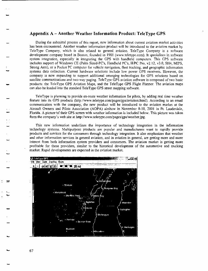
w
H
Appendix A - Another Weather Information Product: TeleType GPS
During the submittal process of this report, new information about current aviation market activitieshas been encountered. Another weather information product will be introduced to the aviation market by
TeleType Company, which is also related to general aviation. TeleType Company is a softwaredevelopment company based in Boston, founded in 1981 (www.teletype.com). It specializes in softwaresystem integration, especially in integrating the GPS with handheld computers. This GPS softwareincludes support of Windows CE (Palm Sized-PC's, Handheld PC's, H/PC Pro, v2.12, v3.0, SH4, MIPS,
Strong Arm), or a Pocket PC computer for vehicle navigation, fleet tracking, and geographic informationsystems data collection. Current hardware solutions include low power GPS receivers. However, thecompany is now expanding to support additional emerging technologies for GPS solutions based onsatellite communications and two-way paging. TeleType GPS aviation software is composed of two basic
products: the TeleType GPS Aviation Maps, and the TeleType GPS Flight Planner. The aviation mapscan also be loaded into the standard TeleType GPS street mapping software.
TeleType is planning to provide en-route weather information for pilots, by adding real time weatherfeature into its GPS products (http://www.teletype.com/pages/gps/aviation.html). According to an emailcommunication with the company, the new product will be introduced to the aviation market at theAircraft Owners and Pilots Association (AOPA) airshow in November 8-10, 2001 in Ft. Lauderdale,Florida. A picture 'of their GPS screen with weather information is included below. This picture was takenfrom the company's web site at http://www.teletype.com/pages/gps/weather.jpg.
This new information underlines the importance of technology integration in the informationtechnology systems. Multipurpose products are popular and manufacturers want to rapidly provideproducts and services for the consumers through technology integration. It also emphasizes that weather
and other information services in general aviation, and in aviation in general, are getting more and moreinterest from both information system providers and consumers. The aviation market is getting moreprofitable for these providers, similar to the historical development of the automotive and truckingmarket. Rapid developments are expected in the aviation market.
"" 67


![TRUCKING INDUSTRY · [ 6 ] TRUCKING INDUSTRY ENVIRONMENTAL BEST PRACTICE GUIDE ThE AUSTRALIAN TRUCKING ASSOCIATION The Australian Trucking Association (ATA) is the national peak body](https://static.fdocuments.net/doc/165x107/5e6e335355a7c4346213f0b4/trucking-6-trucking-industry-environmental-best-practice-guide-the-australian.jpg)